Embed Size (px)
Citation preview
Light and Reflection
Chapter 14
Electromagnetic Waves
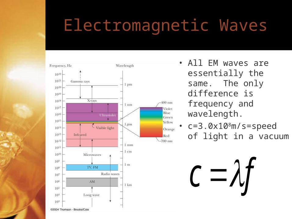
• All EM waves are essentially the same. The only difference is frequency and wavelength.
• c=3.0x10⁸m/s=speed of light in a vacuum
fc
Light
• The portion of the EM spectrum which can be perceived by the eye.
• Ranges from 400nm (purple) to 700nm (red)
• Light waves are transverse.• For geometric optics, light waves
are represented as rays showing the direction of propagation.
Law of Reflection
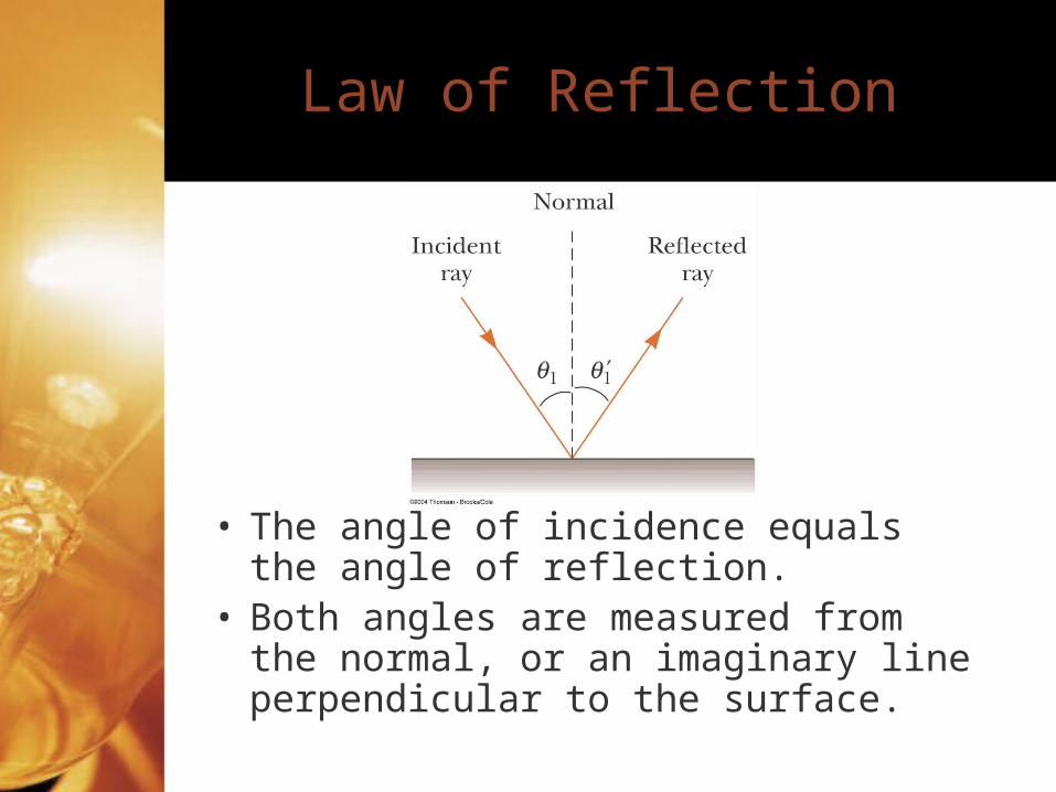
• The angle of incidence equals the angle of reflection.
• Both angles are measured from the normal, or an imaginary line perpendicular to the surface.
Reflection
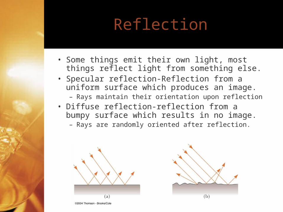
• Some things emit their own light, most things reflect light from something else.
• Specular reflection-Reflection from a uniform surface which produces an image.– Rays maintain their orientation upon reflection
• Diffuse reflection-reflection from a bumpy surface which results in no image.– Rays are randomly oriented after reflection.
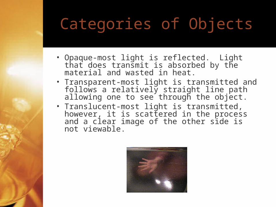
Categories of Objects
• Opaque-most light is reflected. Light that does transmit is absorbed by the material and wasted in heat.
• Transparent-most light is transmitted and follows a relatively straight line path allowing one to see through the object.
• Translucent-most light is transmitted, however, it is scattered in the process and a clear image of the other side is not viewable.
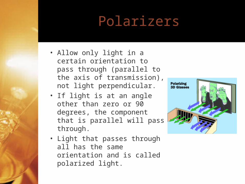
Polarizers
• Allow only light in a certain orientation to pass through (parallel to the axis of transmission), not light perpendicular.
• If light is at an angle other than zero or 90 degrees, the component that is parallel will pass through.
• Light that passes through all has the same orientation and is called polarized light.
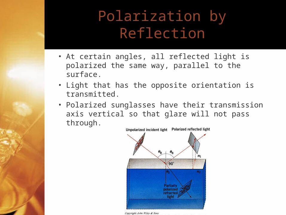
Polarization by Reflection
• At certain angles, all reflected light is polarized the same way, parallel to the surface.
• Light that has the opposite orientation is transmitted.
• Polarized sunglasses have their transmission axis vertical so that glare will not pass through.
Ray Diagrams
• Object-the thing that is acting as the source of the light.– You, when you are looking in the mirror.– p=distance from mirror to object
• Image-the reconvergence or apparent reconvergence of light. – Your reflection, when you are looking in the
mirror.– q=distance from image to mirror
Ray Diagrams
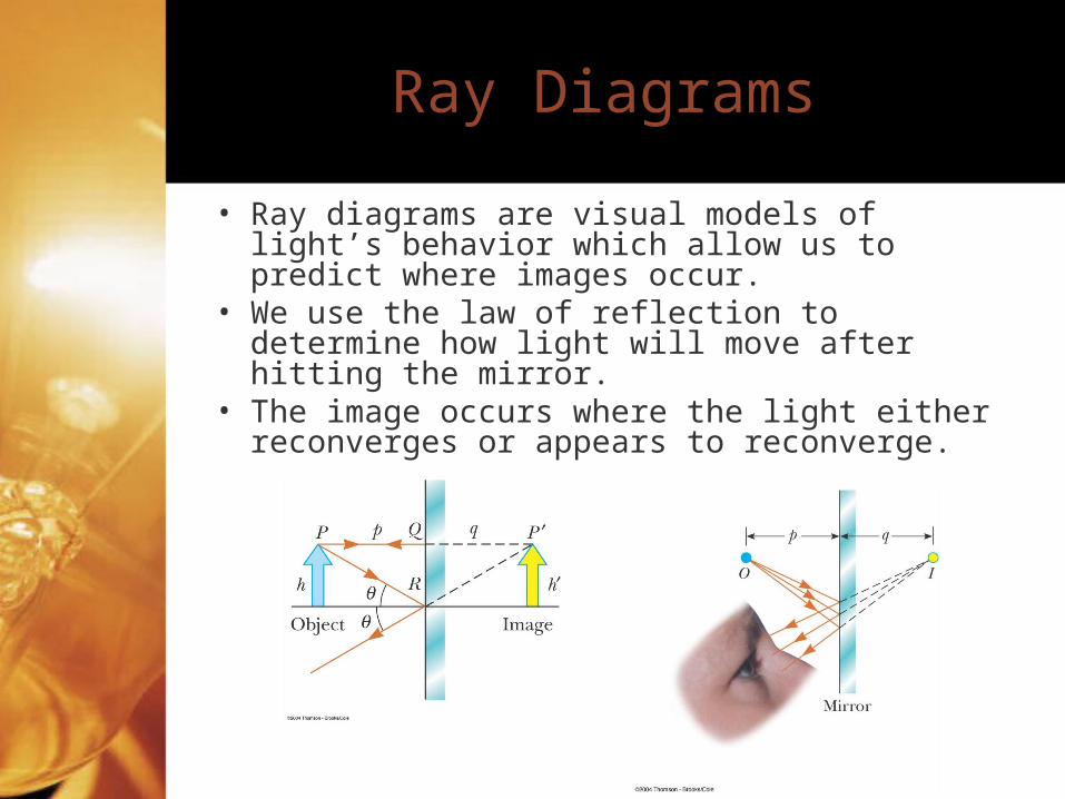
• Ray diagrams are visual models of light’s behavior which allow us to predict where images occur.
• We use the law of reflection to determine how light will move after hitting the mirror.
• The image occurs where the light either reconverges or appears to reconverge.
Image Types
• Virtual images-images where light does not reconverge. If one were to stand where the image was apparently located, nothing would be there. Flat mirrors produce these
• Real images-images that occur when light actually does reconverge. Real images can be projected on a screen or appear to float. The pig demo shows this.
• For a virtual image, you need to look at the mirror or lens to see the image. For a real image, you don’t. Instead you can look directly at the image location.
• One can determine whether a real or virtual image will be produced by either ray diagrams or equations.
Mirror Terminology
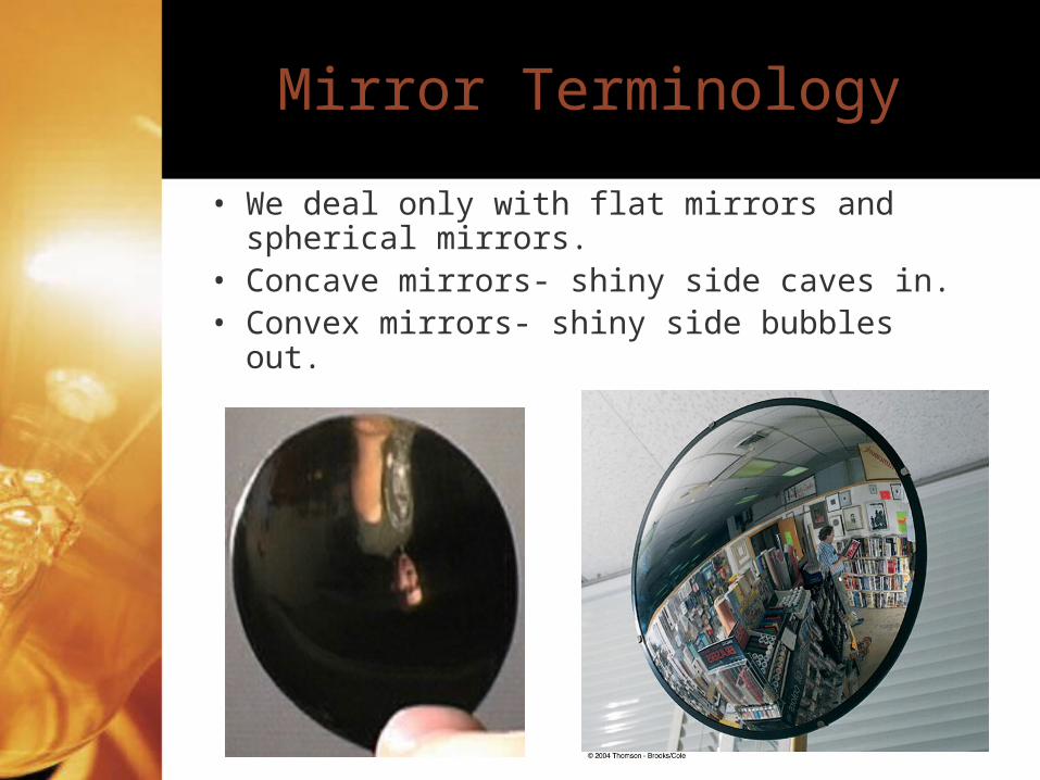
• We deal only with flat mirrors and spherical mirrors.
• Concave mirrors- shiny side caves in.• Convex mirrors- shiny side bubbles out.
Curved Mirror Terminology
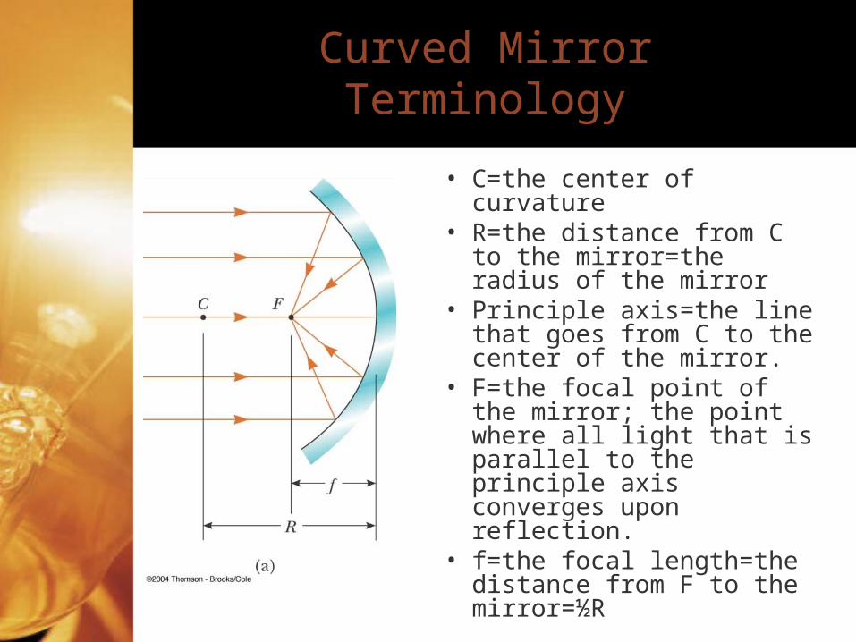
• C=the center of curvature• R=the distance from C to
the mirror=the radius of the mirror
• Principle axis=the line that goes from C to the center of the mirror.
• F=the focal point of the mirror; the point where all light that is parallel to the principle axis converges upon reflection.
• f=the focal length=the distance from F to the mirror=½R
Ray Diagram Mirror Rules
• Incident rays which are parallel to the principle axis will reflect through (aligned with) F.
• Incident rays which pass through (are aligned with) F will reflect parallel to the principle axis.
• Example
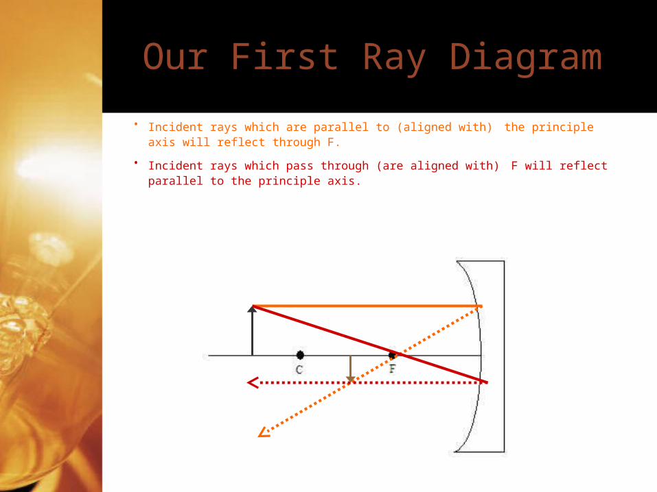
Our First Ray Diagram
• Incident rays which are parallel to (aligned with) the principle axis will reflect through F.
• Incident rays which pass through (are aligned with) F will reflect parallel to the principle axis.
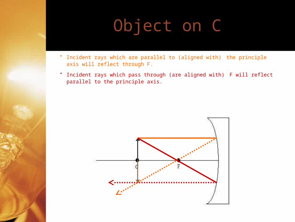
Object on C
• Incident rays which are parallel to (aligned with) the principle axis will reflect through F.
• Incident rays which pass through (are aligned with) F will reflect parallel to the principle axis.
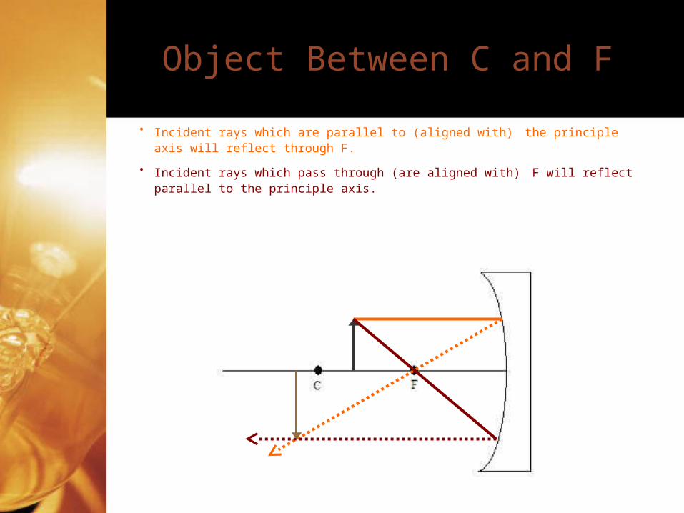
Object Between C and F
• Incident rays which are parallel to (aligned with) the principle axis will reflect through F.
• Incident rays which pass through (are aligned with) F will reflect parallel to the principle axis.
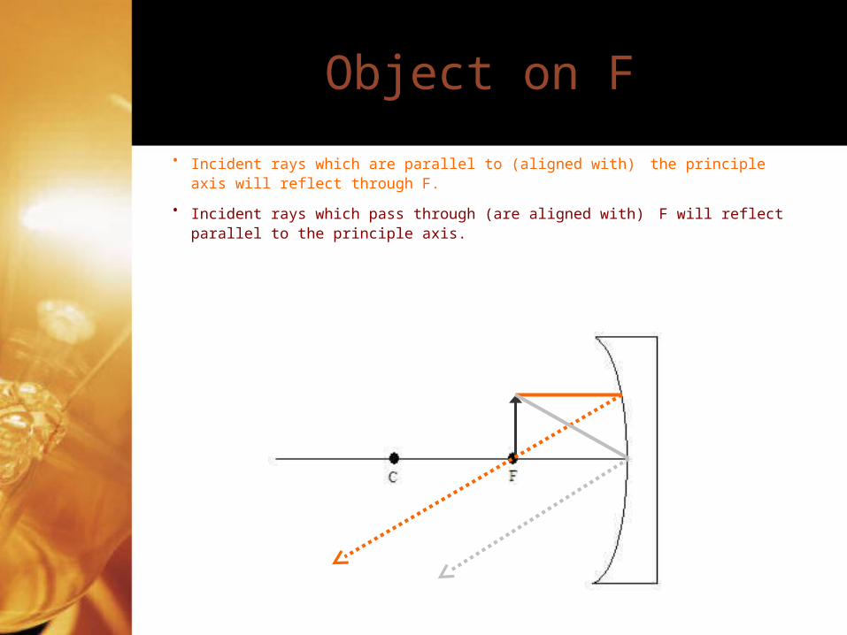
Object on F
• Incident rays which are parallel to (aligned with) the principle axis will reflect through F.
• Incident rays which pass through (are aligned with) F will reflect parallel to the principle axis.
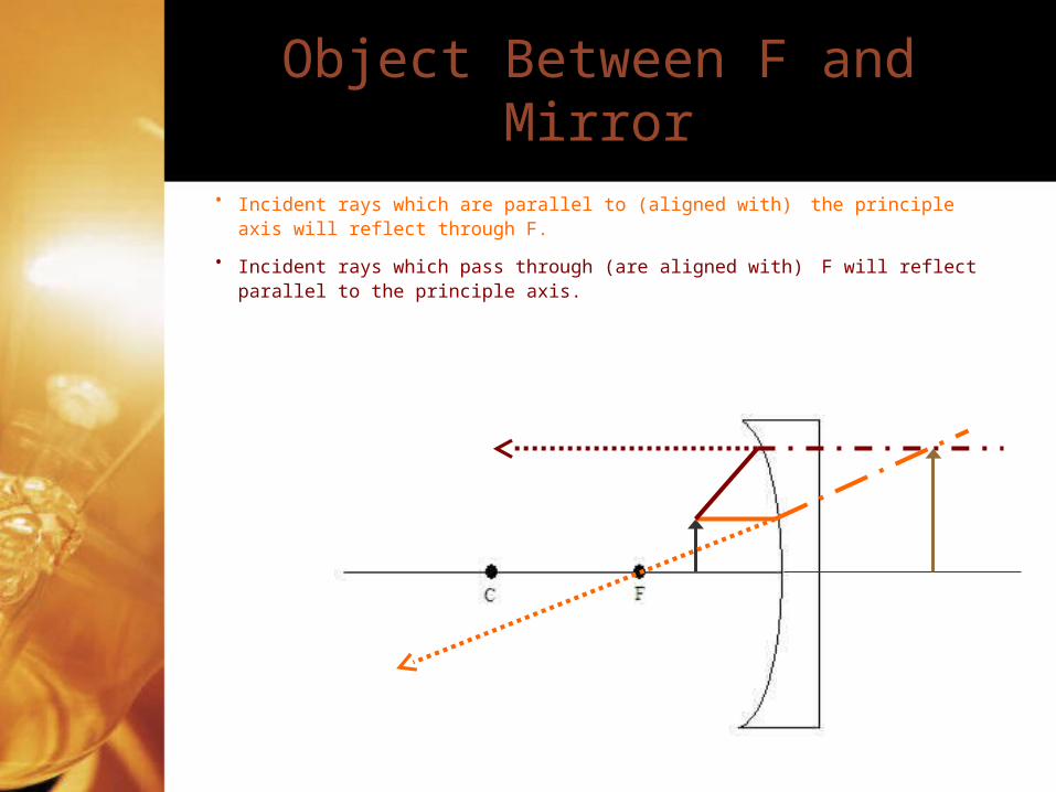
Object Between F and Mirror
• Incident rays which are parallel to (aligned with) the principle axis will reflect through F.
• Incident rays which pass through (are aligned with) F will reflect parallel to the principle axis.
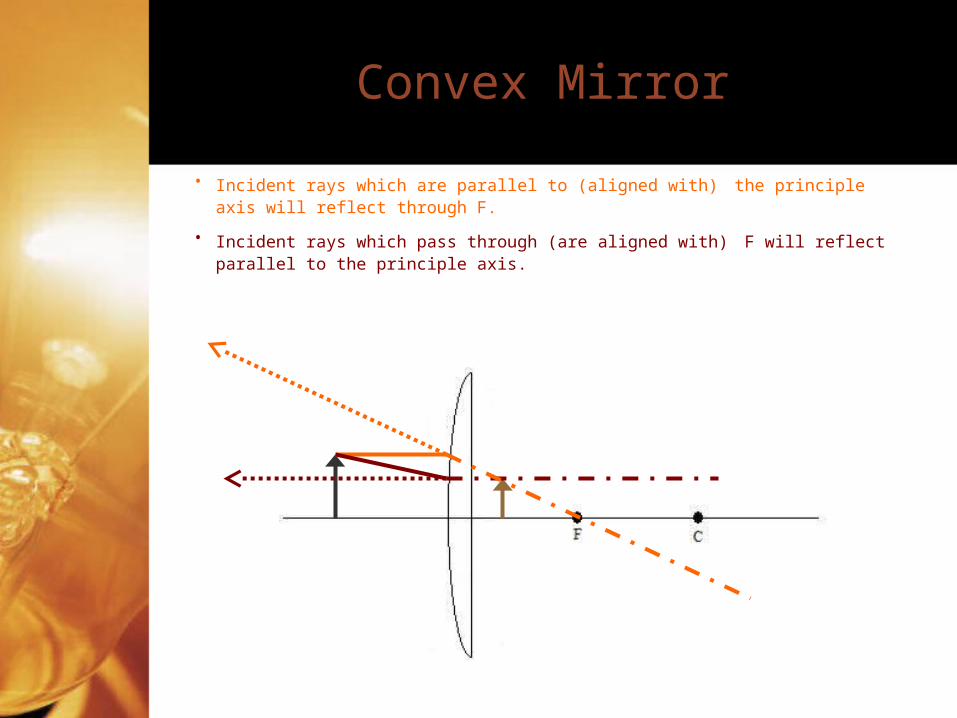
Convex Mirror
• Incident rays which are parallel to (aligned with) the principle axis will reflect through F.
• Incident rays which pass through (are aligned with) F will reflect parallel to the principle axis.
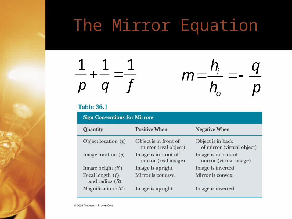
The Mirror Equation
fqp
111
p
q
h
hm
o
i
Practice Problems
• A candle is reflected in a mirror with a magnification of -3.33. The image is formed 7.2cm from the mirror’s surface.– Is the image upright or inverted?– What is the distance of the object to the mirror?– What is the focal length of the mirror?– Is the image virtual or real?
• A convex security mirror shows the reflection of a thief. The thief is 2.5m from the mirror and 1.8m tall. If the image of the thief is 3cm tall, what is the distance of the image to the mirror and the focal length of the mirror?
Practice
• A concave mirror produces a virtual image that is 5cm from the mirror. If the focal length of the mirror is 3.5cm and the object is 30mm tall, how large is the image and how is it oriented?
Additive Color Mixing
• Additive color mixing is using various colors of light to make different, intermediate colors.
• White light is how we perceive all of the colors together.
• Primary colors of light are red, green, and blue.
• Mixing different primary colors in different combinations makes us perceive the intermediate colors.
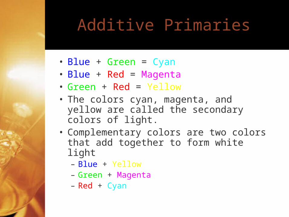
Additive Primaries
• Blue + Green = Cyan• Blue + Red = Magenta• Green + Red = Yellow• The colors cyan, magenta, and yellow
are called the secondary colors of light.• Complementary colors are two colors
that add together to form white light– Blue + Yellow– Green + Magenta– Red + Cyan
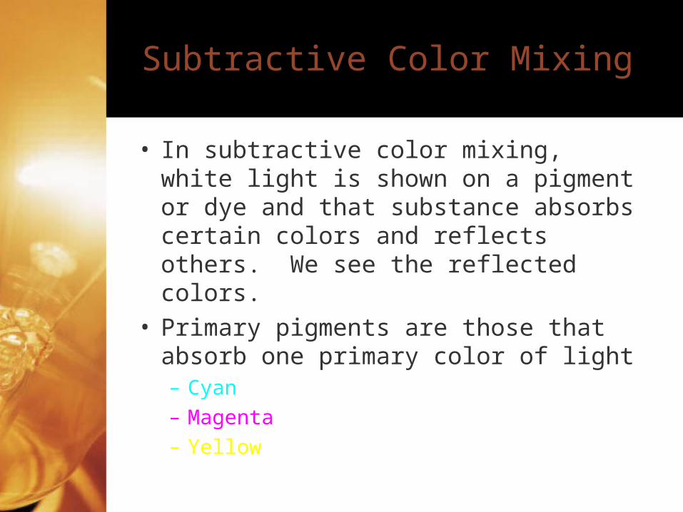
Subtractive Color Mixing
• In subtractive color mixing, white light is shown on a pigment or dye and that substance absorbs certain colors and reflects others. We see the reflected colors.
• Primary pigments are those that absorb one primary color of light– Cyan– Magenta– Yellow
Color Perception By the Eye
• Rods-can’t distinguish between color but are activated at lower light levels.
• Cones-can see color but are operational only at upper light levels.– Three types; red, green, blue– Color blindness results from missing one or
more types of cones.
• Color Blindness Test• Color Blindness Simulation
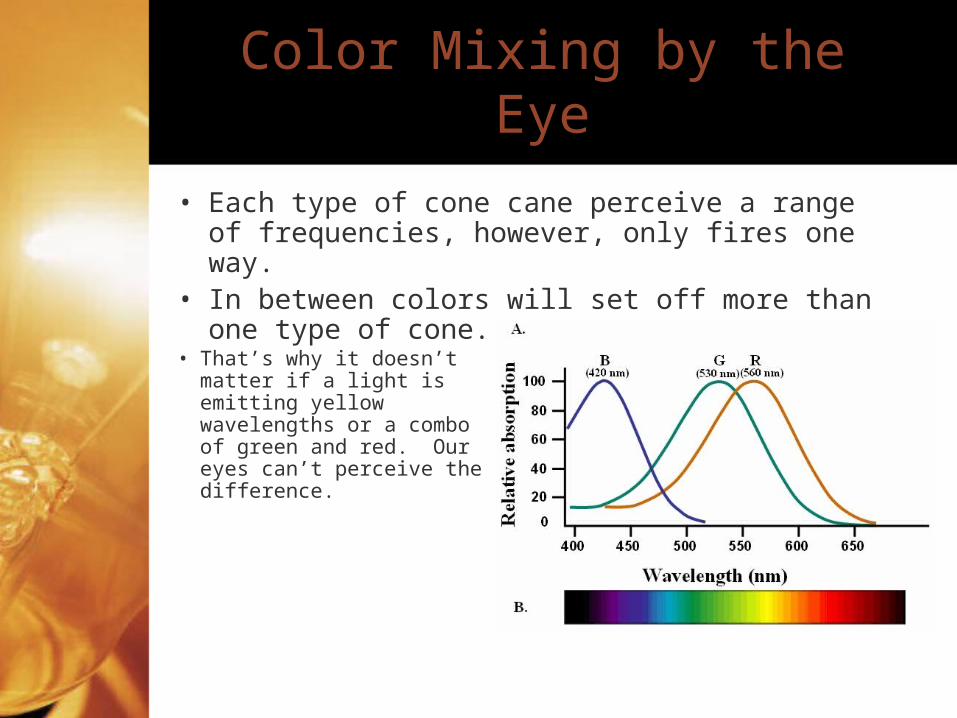
Color Mixing by the Eye
• Each type of cone cane perceive a range of frequencies, however, only fires one way.
• In between colors will set off more than one type of cone.
• That’s why it doesn’t matter if a light is emitting yellow wavelengths or a combo of green and red. Our eyes can’t perceive the difference.