Embed Size (px)
Citation preview
Author's Accepted Manuscript
Ligament-type liquid disintegration by a spin-ning wheel
Benjamin Bizjan, Brane Širok, Marko Hočevar,Alen Orbanić
PII: S0009-2509(14)00208-5DOI: http://dx.doi.org/10.1016/j.ces.2014.04.043Reference: CES11625
To appear in: Chemical Engineering Science
Received date: 7 January 2014Revised date: 21 March 2014Accepted date: 30 April 2014
Cite this article as: Benjamin Bizjan, Brane Širok, Marko Hočevar, AlenOrbanić, Ligament-type liquid disintegration by a spinning wheel, ChemicalEngineering Science, http://dx.doi.org/10.1016/j.ces.2014.04.043
This is a PDF file of an unedited manuscript that has been accepted forpublication. As a service to our customers we are providing this early version ofthe manuscript. The manuscript will undergo copyediting, typesetting, andreview of the resulting galley proof before it is published in its final citable form.Please note that during the production process errors may be discovered whichcould affect the content, and all legal disclaimers that apply to the journalpertain.
www.elsevier.com/locate/ces
LigamentType Liquid Disintegration by a Spinning Wheel
*Benjamin Bizjan1,2, Brane Širok1, Marko Hočevar1, Alen Orbanić 2
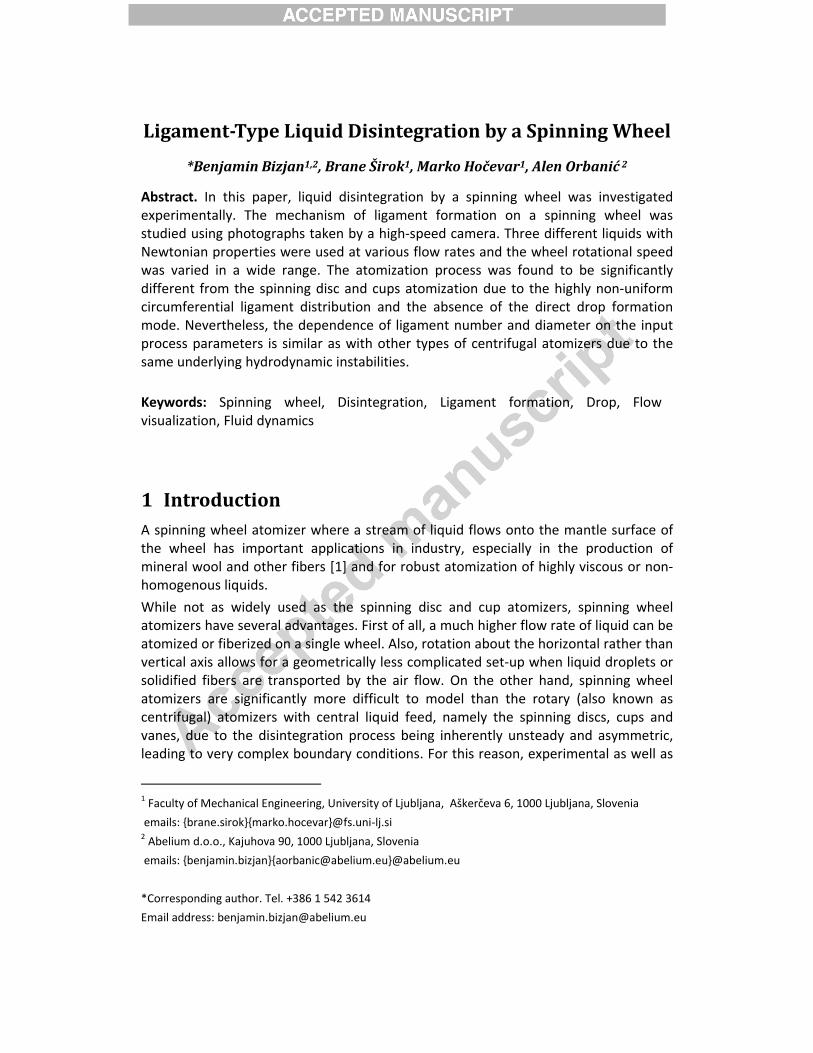
Abstract. In this paper, liquid disintegration by a spinning wheel was investigated experimentally. The mechanism of ligament formation on a spinning wheel was studied using photographs taken by a high‐speed camera. Three different liquids with Newtonian properties were used at various flow rates and the wheel rotational speed was varied in a wide range. The atomization process was found to be significantly different from the spinning disc and cups atomization due to the highly non‐uniform circumferential ligament distribution and the absence of the direct drop formation mode. Nevertheless, the dependence of ligament number and diameter on the input process parameters is similar as with other types of centrifugal atomizers due to the same underlying hydrodynamic instabilities.
Keywords: Spinning wheel, Disintegration, Ligament formation, Drop, Flow visualization, Fluid dynamics
1 Introduction A spinning wheel atomizer where a stream of liquid flows onto the mantle surface of the wheel has important applications in industry, especially in the production of mineral wool and other fibers [1] and for robust atomization of highly viscous or non‐homogenous liquids.
While not as widely used as the spinning disc and cup atomizers, spinning wheel atomizers have several advantages. First of all, a much higher flow rate of liquid can be atomized or fiberized on a single wheel. Also, rotation about the horizontal rather than vertical axis allows for a geometrically less complicated set‐up when liquid droplets or solidified fibers are transported by the air flow. On the other hand, spinning wheel atomizers are significantly more difficult to model than the rotary (also known as centrifugal) atomizers with central liquid feed, namely the spinning discs, cups and vanes, due to the disintegration process being inherently unsteady and asymmetric, leading to very complex boundary conditions. For this reason, experimental as well as
1 Faculty of Mechanical Engineering, University of Ljubljana, Aškerčeva 6, 1000 Ljubljana, Slovenia
emails: {brane.sirok}{marko.hocevar}@fs.uni‐lj.si 2 Abelium d.o.o., Kajuhova 90, 1000 Ljubljana, Slovenia
emails: {benjamin.bizjan}{[email protected]}@abelium.eu
*Corresponding author. Tel. +386 1 542 3614
Email address: [email protected]
‐ 2 ‐
numerical research and modeling of spinning wheel atomizers has so far been very scarce unlike some other types of rotary atomizers [3, 5, 6, 7, 8, 9]. Due to the fact that all of these atomizers employ the centrifugal force for liquid disintegration, it is reasonable to assume that their underlying mechanisms of the hydrodynamic instabilities are similar on a fundamental level – an assumption that was verified experimentally in our paper. Our experiment was conducted by the means of the high‐speed camera visualization of the atomization process and the acquired images were a subject to both qualitative and quantitative analysis. The main purpose of the present study was to characterize the atomizer operation at different rotational speeds and liquid flow rates and compare it to the other types of rotary atomizers previously studied by other authors.
This paper is organized as follows. A description of the centrifugal atomization mechanism and the overview of other authors’ research is provided in section 2. In section 3, the experimental set‐up used for our study is introduced. Section 4 presents the results of image analysis, including the identification of typical atomization regimes as well as quantitative properties such as the number and distribution of ligaments and the predicted drop diameter.
2 Liquid disintegration mechanism and methodology It is widely agreed that the liquid disintegration on rotary atomizers occurs as a result of hydrodynamic instabilities such as the Kelvin‐Helmholtz (Helmholtz 1868, Kelvin 1871) and Rayleigh‐Taylor (Rayleigh 1900, Taylor 1950) instabilities that develop on the liquid film and are driven by the shear and centrifugal forces. When a liquid stream falls onto the mantle surface of a spinning wheel, it is drawn into motion by the viscous and adhesive forces, forming a thin film slightly wider than the liquid stream. Initial liquid film disturbances required for development of unstable waves are most likely caused by the Kelvin‐Helmholtz instability induced by velocity slip between the film and the surrounding fluid (air in our case) as well as by fluctuations in the liquid flow rate. The main wave formation mechanism however is the Rayleigh‐Taylor instability, for which a detailed mathematical formulation was provided by Taylor [2]. It occurs when a layer of denser fluid is pushed towards the lighter fluid by the gravity force or, in case of rotary atomizers, by centrifugal force acting upon the rotating liquid film.
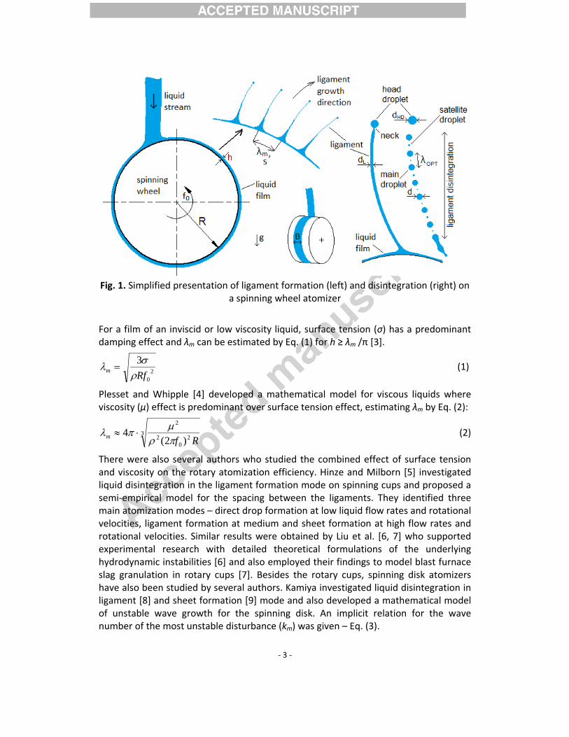
According to Eisenklam [3], unstable waves forming on the liquid film surface due to the Rayleigh‐Taylor instability grow at different rates depending on their wavelength. The waves below a certain cutoff wavelength are fully damped by viscous and surface tension forces while at higher wavelengths where the centrifugal force is greater than the aforementioned damping forces, the waves grow exponentially and at different growth rates. It can be assumed that the fastest growing wave (wavelength λm) becomes predominant [3] and transforms into the circumferential spacing (s) between the emerging liquid ligaments (Fig. 1). In Fig. 1, f0 denotes the wheel rotational speed in [Hz] (equal to angular velocity ω in [rad/s] divided by 2π), R the wheel radius, h the liquid film thickness and B the film width.
‐ 3 ‐
Fig. 1. Simplified presentation of ligament formation (left) and disintegration (right) on
a spinning wheel atomizer
For a film of an inviscid or low viscosity liquid, surface tension (σ) has a predominant damping effect and λm can be estimated by Eq. (1) for h ≥ λm /π [3].
20
3Rfm ρσλ = (1)
Plesset and Whipple [4] developed a mathematical model for viscous liquids where viscosity (μ) effect is predominant over surface tension effect, estimating λm by Eq. (2):
32
02
2
)2(4
Rfm πρμπλ ⋅≈ (2)
There were also several authors who studied the combined effect of surface tension and viscosity on the rotary atomization efficiency. Hinze and Milborn [5] investigated liquid disintegration in the ligament formation mode on spinning cups and proposed a semi‐empirical model for the spacing between the ligaments. They identified three main atomization modes – direct drop formation at low liquid flow rates and rotational velocities, ligament formation at medium and sheet formation at high flow rates and rotational velocities. Similar results were obtained by Liu et al. [6, 7] who supported experimental research with detailed theoretical formulations of the underlying hydrodynamic instabilities [6] and also employed their findings to model blast furnace slag granulation in rotary cups [7]. Besides the rotary cups, spinning disk atomizers have also been studied by several authors. Kamiya investigated liquid disintegration in ligament [8] and sheet formation [9] mode and also developed a mathematical model of unstable wave growth for the spinning disk. An implicit relation for the wave number of the most unstable disturbance (km) was given – Eq. (3).
‐ 4 ‐
( ) 0111383 222 =−
⎥⎥⎦
⎤
⎢⎢⎣
⎡⎟⎟⎠
⎞⎜⎜⎝
⎛
⋅++−+ We
OhkOhkk
mmm (3)
In Eq. (3), We = ρ(2πf0)2R3/σ is the Weber number and Oh = μ/(ρRσ)1/2 = We1/2/Re the
Ohnesorge number (the author used stability number given as St = Oh2). We represents the ratio between inertial and surface tension forces while Oh is proportional to the ratio of viscous to inertial and surface tension forces. Re is the Reynolds number, defined as the ratio between the inertial and viscous forces. Note that here, We, Oh and Re are defined for liquid film and not for ligaments or droplets and are given for the nominal rotational speed of the atomizer (slip between the film and apparatus surface is not considered). While Eq. (3) may not be optimally suited for geometry of our atomizer (spinning wheel), it is the most advanced known analytical form for estimation of km taking both liquid viscosity and surface tension in consideration. Besides, the very complex boundary conditions (asymmetric fluid feed, transient ligament formation process…) prevented us from deducing a specific analytical equation for km for the spinning wheel atomizer. Therefore, Eq. (3) will be used in conjunction with experimental data to determine to what extent the spinning wheel atomization resembles the spinning disc and cup atomization process.
Analogously to λm and s, the wave number is assumed to be the same as the number of ligaments N (provided that each wave grows into one ligament) and the relation between km and λm is given by Eq. 4:
mm Rk λπ /2= (4)
Most of the authors have so far used N rather than s in atomization experiments and the same methodology will be utilized in our paper. When speaking of empirical formulations, a good experimental data fit for N may be the one given by Eq. (5) where a1, a2 and C are constants to be determined [6]:
21 aa OhWeCN ⋅⋅= (5)
In our case, we may expand the model from Eq. (5) to also account for the flow rate (Q) effect. We introduce a dimensionless flow rate q as proposed by Širok et al. [1] in dimensionless analysis of a mineral wool spinning machine – Eq. (6).
σρ
σρ
RdQ
RBQq
N
≈= (6)
In Eq. (6), B is the width of the liquid film on the wheel mantle surface and we estimate it to be approximately the same as the liquid nozzle diameter, dN.
The expanded model for the number of ligaments can now be written by Eq. (7): 321 aaa qOhWeCN ⋅⋅⋅= (7)
Constants a1, a2, a3 and C are to be determined by fitting the model to experimental data by a least squares fit.
‐ 5 ‐
Once the ligaments have formed from the unstable liquid film waves, another important aspect is their growth and breakup to droplets. One typical parameter is the ligament diameter (dL) before disintegration occurs (Fig. 1 right). A theoretical equation for ligament diameter on spinning cups was derived by Liu et al. [6, 7] but is of little significance for our research as in case of a spinning wheel, ligament formation and breakup is a transient phenomenon, unlike the spinning disk and cup atomizers where ligaments grow continuously and at the same time break up into droplets at a certain distance from the apparatus edge. However, a formulation analogous to Eq. (7) can be used for fitting of experimental data as suggested by Širok et al. [1] – Eq. (8).
321 aaaL qOhWeCRd
⋅⋅⋅= (8)
Constants a1, a2, a3 and C can be obtained by fitting Eq. (8) to experimental dL/R data.
The ligament diameter can be an output process parameter in case of fiber production where fiber diameter after melt solidification is practically equal to dL. In case of atomization however, dL is an intermediate parameter from which drop diameter after ligament breakup can be calculated, and jet breakup theory can be applied. The jet breakup mechanism was investigated by numerous authors including Lord Rayleigh (1878), Weber (1931), Ohnesorge (1936) and Miesse (1955) and a comprehensive overview of jet breakup phenomena was provided by Lefebvre [10]. Lefebvre developed a jet breakup type classification as a function of Reynolds and Ohnesorge number. It was noted that for low enough Reynolds and Weber number when aerodynamic effects are negligible (which is typically true for spinning disc, cup and wheel atomizers), the Rayleigh (also known as varicose) type jet breakup occurs. For the Rayleigh‐type breakup, it is typical that the radially symmetric dilatational waves are formed along the length of a ligament by the interaction of primary disturbances in the liquid and surface tension forces acting to minimize the total surface free energy of the liquid‐gas interface [11].
The wavelength of the fastest growing dilatational waves that form along the ligament surface (λOPT, see Fig. 1) is given by Eq. (9) [12]:
5.0312 ⎟
⎟⎠
⎞⎜⎜⎝
⎛+=
LLOPT d
dρσμπλ (9)
For a ligament of known diameter dL, mean diameter of droplets d to which it disintegrates can be predicted by Eq. (10) [12]:
3 25.1 LOPT dd λ= (10)
For an inviscid liquid, Eq. (10) yields d = 1.89 dL and dL increases slowly with growing viscosity.
‐ 6 ‐
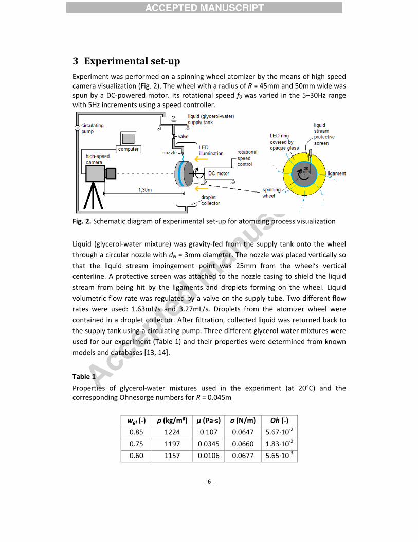
3 Experimental setup Experiment was performed on a spinning wheel atomizer by the means of high‐speed camera visualization (Fig. 2). The wheel with a radius of R = 45mm and 50mm wide was spun by a DC‐powered motor. Its rotational speed f0 was varied in the 5–30Hz range with 5Hz increments using a speed controller.
Fig. 2. Schematic diagram of experimental set‐up for atomizing process visualization
Liquid (glycerol‐water mixture) was gravity‐fed from the supply tank onto the wheel through a circular nozzle with dN = 3mm diameter. The nozzle was placed vertically so that the liquid stream impingement point was 25mm from the wheel’s vertical centerline. A protective screen was attached to the nozzle casing to shield the liquid stream from being hit by the ligaments and droplets forming on the wheel. Liquid volumetric flow rate was regulated by a valve on the supply tube. Two different flow rates were used: 1.63mL/s and 3.27mL/s. Droplets from the atomizer wheel were contained in a droplet collector. After filtration, collected liquid was returned back to the supply tank using a circulating pump. Three different glycerol‐water mixtures were used for our experiment (Table 1) and their properties were determined from known models and databases [13, 14].
Table 1
Properties of glycerol‐water mixtures used in the experiment (at 20°C) and the corresponding Ohnesorge numbers for R = 0.045m
wgl (‐) ρ (kg/m³) μ (Pa∙s) σ (N/m) Oh (‐)
0.85 1224 0.107 0.0647 5.67∙10‐2
0.75 1197 0.0345 0.0660 1.83∙10‐2
0.60 1157 0.0106 0.0677 5.65∙10‐3
‐ 7 ‐
By using two different flow rates, three kinds of liquids and six different rotational speeds, we produced a total of 36 operating points. Physical properties of different liquids are reflected by the Ohnesorge number (Oh).
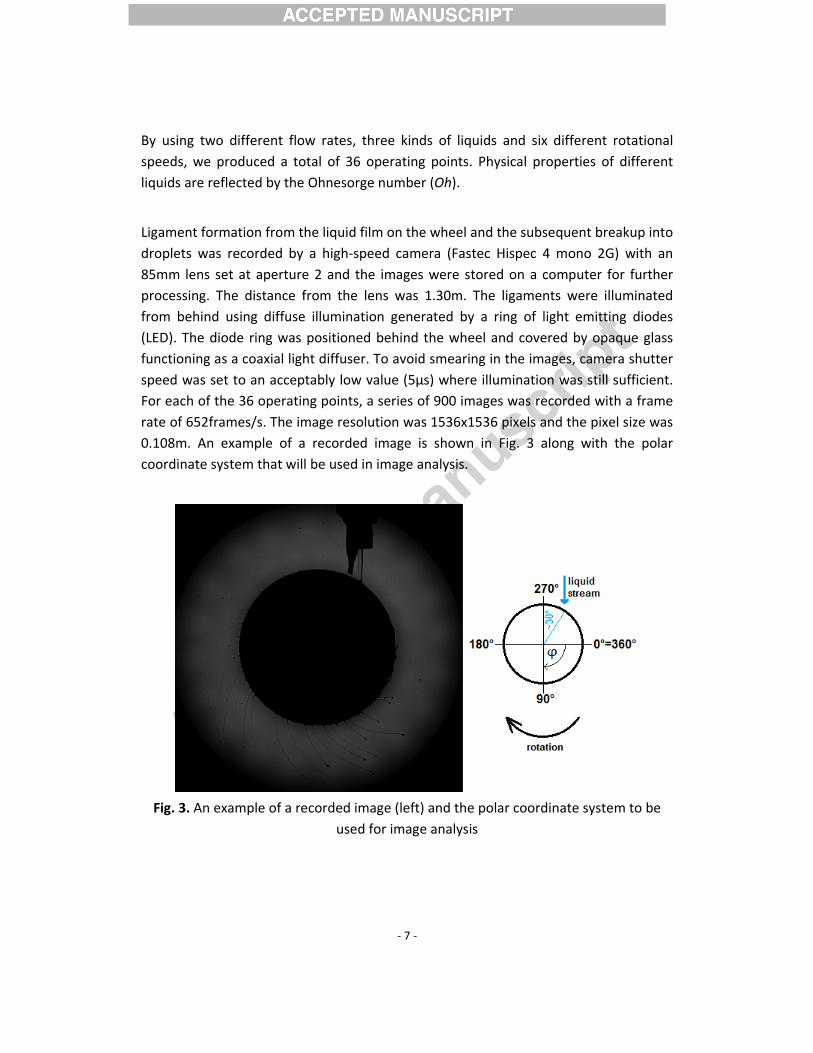
Ligament formation from the liquid film on the wheel and the subsequent breakup into droplets was recorded by a high‐speed camera (Fastec Hispec 4 mono 2G) with an 85mm lens set at aperture 2 and the images were stored on a computer for further processing. The distance from the lens was 1.30m. The ligaments were illuminated from behind using diffuse illumination generated by a ring of light emitting diodes (LED). The diode ring was positioned behind the wheel and covered by opaque glass functioning as a coaxial light diffuser. To avoid smearing in the images, camera shutter speed was set to an acceptably low value (5μs) where illumination was still sufficient. For each of the 36 operating points, a series of 900 images was recorded with a frame rate of 652frames/s. The image resolution was 1536x1536 pixels and the pixel size was 0.108m. An example of a recorded image is shown in Fig. 3 along with the polar coordinate system that will be used in image analysis.
Fig. 3. An example of a recorded image (left) and the polar coordinate system to be
used for image analysis
‐ 8 ‐
4 Results and discussions 4.1 Qualitative analysis The qualitative analysis by visual inspection of recorded images indicates the presence of several different liquid disintegration regimes depending on the operating parameters of the atomizer. As the wheel rotational speed (f0) proved to have by far the most significant effect on the liquid disintegration, different operating regimes will be presented as the function of f0.
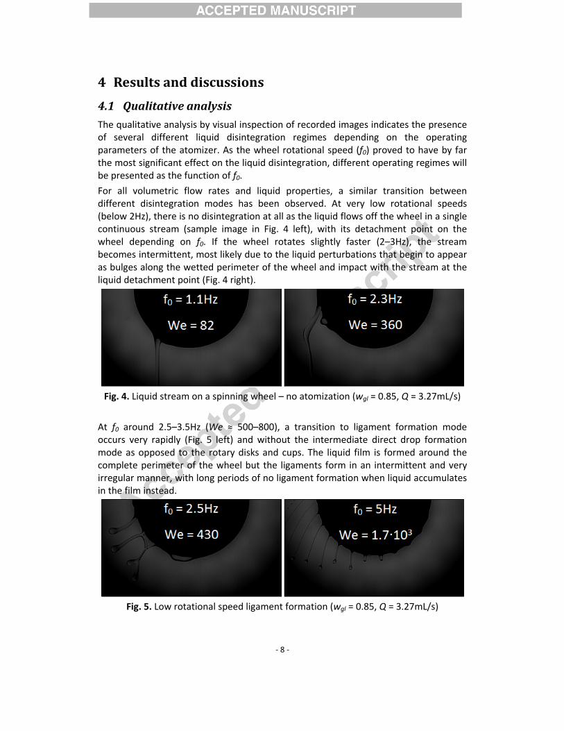
For all volumetric flow rates and liquid properties, a similar transition between different disintegration modes has been observed. At very low rotational speeds (below 2Hz), there is no disintegration at all as the liquid flows off the wheel in a single continuous stream (sample image in Fig. 4 left), with its detachment point on the wheel depending on f0. If the wheel rotates slightly faster (2–3Hz), the stream becomes intermittent, most likely due to the liquid perturbations that begin to appear as bulges along the wetted perimeter of the wheel and impact with the stream at the liquid detachment point (Fig. 4 right).
Fig. 4. Liquid stream on a spinning wheel – no atomization (wgl = 0.85, Q = 3.27mL/s)
At f0 around 2.5–3.5Hz (We ≈ 500–800), a transition to ligament formation mode occurs very rapidly (Fig. 5 left) and without the intermediate direct drop formation mode as opposed to the rotary disks and cups. The liquid film is formed around the complete perimeter of the wheel but the ligaments form in an intermittent and very irregular manner, with long periods of no ligament formation when liquid accumulates in the film instead.
Fig. 5. Low rotational speed ligament formation (wgl = 0.85, Q = 3.27mL/s)
‐ 9 ‐
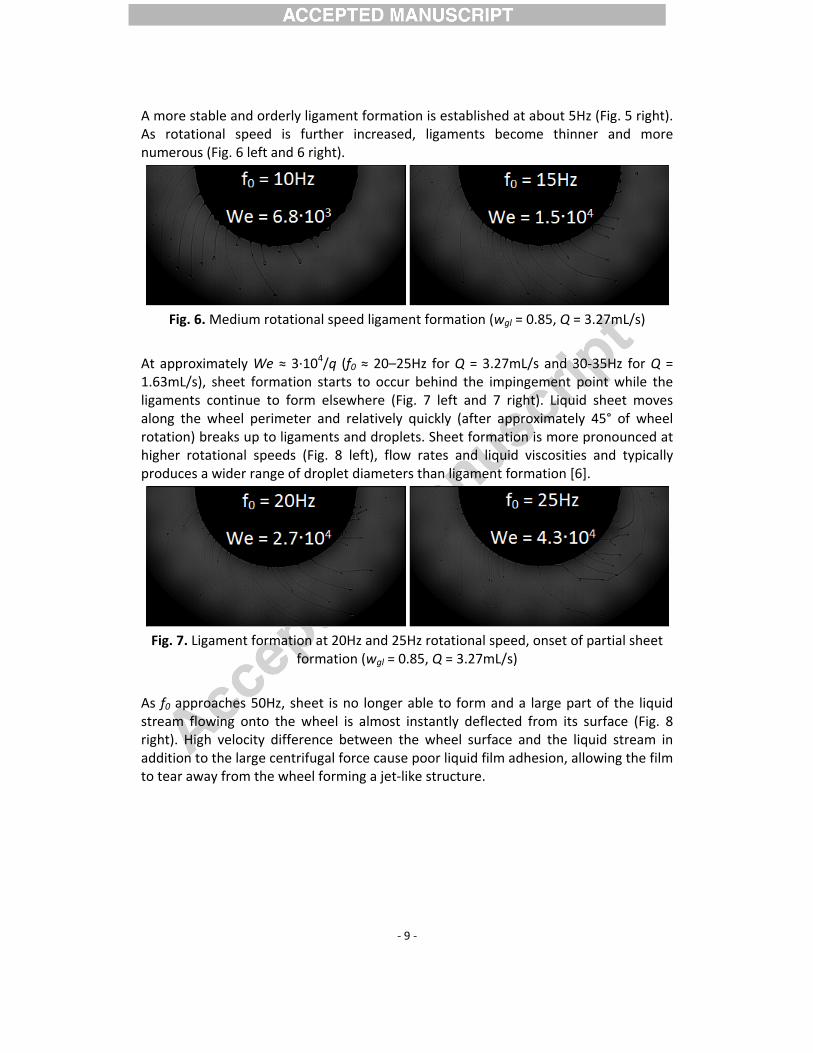
A more stable and orderly ligament formation is established at about 5Hz (Fig. 5 right). As rotational speed is further increased, ligaments become thinner and more numerous (Fig. 6 left and 6 right).
Fig. 6. Medium rotational speed ligament formation (wgl = 0.85, Q = 3.27mL/s)
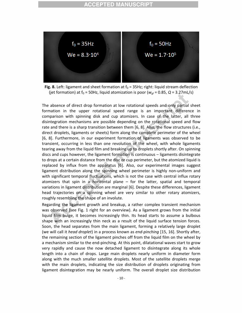
At approximately We ≈ 3∙104/q (f0 ≈ 20–25Hz for Q = 3.27mL/s and 30‐35Hz for Q = 1.63mL/s), sheet formation starts to occur behind the impingement point while the ligaments continue to form elsewhere (Fig. 7 left and 7 right). Liquid sheet moves along the wheel perimeter and relatively quickly (after approximately 45° of wheel rotation) breaks up to ligaments and droplets. Sheet formation is more pronounced at higher rotational speeds (Fig. 8 left), flow rates and liquid viscosities and typically produces a wider range of droplet diameters than ligament formation [6].
Fig. 7. Ligament formation at 20Hz and 25Hz rotational speed, onset of partial sheet
formation (wgl = 0.85, Q = 3.27mL/s)
As f0 approaches 50Hz, sheet is no longer able to form and a large part of the liquid stream flowing onto the wheel is almost instantly deflected from its surface (Fig. 8 right). High velocity difference between the wheel surface and the liquid stream in addition to the large centrifugal force cause poor liquid film adhesion, allowing the film to tear away from the wheel forming a jet‐like structure.
‐ 10 ‐
Fig. 8. Left: ligament and sheet formation at f0 = 35Hz; right: liquid stream deflection (jet formation) at f0 = 50Hz, liquid atomization is poor (wgl = 0.85, Q = 3.27mL/s)
The absence of direct drop formation at low rotational speeds and only partial sheet formation in the upper rotational speed range is an important difference in comparison with spinning disk and cup atomizers. In case of the latter, all three disintegration mechanisms are possible depending on the rotational speed and flow rate and there is a sharp transition between them [6, 8]. Also, the flow structures (i.e., direct droplets, ligaments or sheets) form along the complete perimeter of the wheel [6, 8]. Furthermore, in our experiment formation of ligaments was observed to be transient, occurring in less than one revolution of the wheel, with whole ligaments tearing away from the liquid film and breaking up to droplets shortly after. On spinning discs and cups however, the ligament formation is continuous – ligaments disintegrate to drops at a certain distance from the disc or cup perimeter, but the atomized liquid is replaced by influx from the apparatus [6]. Also, our experimental images suggest ligament distribution along the spinning wheel perimeter is highly non‐uniform and with significant temporal fluctuations, which is not the case with central influx rotary atomizers that spin in a horizontal plane – for the latter, spatial and temporal variations in ligament distribution are marginal [6]. Despite these differences, ligament head trajectories on a spinning wheel are very similar to other rotary atomizers, roughly resembling the shape of an involute.
Regarding the ligament growth and breakup, a rather complex transient mechanism was observed (see Fig. 1 right for an overview). As a ligament grows from the initial liquid film bulge, it becomes increasingly thin. Its head starts to assume a bulbous shape with an increasingly thin neck as a result of the liquid surface tension forces. Soon, the head separates from the main ligament, forming a relatively large droplet (we will call it head droplet) in a process known as end‐pinching [15, 16]. Shortly after, the remaining section of the ligament pinches off from the liquid film on the wheel by a mechanism similar to the end‐pinching. At this point, dilatational waves start to grow very rapidly and cause the now detached ligament to disintegrate along its whole length into a chain of drops. Large main droplets nearly uniform in diameter form along with the much smaller satellite droplets. Most of the satellite droplets merge with the main droplets, indicating the size distribution of droplets originating from ligament disintegration may be nearly uniform. The overall droplet size distribution
‐ 11 ‐
however is bimodal due to the large head droplets that previously pinch off the ligament and represent a significant mass fraction of the total liquid mass flow, especially at lower rotational speeds when their diameter is the largest.
Due to the fact that the ligaments form in a vertically oriented plane, the contribution of gravity to the total body force acting on ligaments varies along the wheel perimeter. According to Liu et al. [6], gravitational effects are negligible when the centrifugal acceleration is high with respect to the gravitational acceleration, i.e. (2πf0)²R > 10g. In our case, the centrifugal acceleration ranges between 4.5g and 163g and is only below 10g for operating points with f0 = 5Hz, while for all the other operating points (f0 = 10–30Hz), we assume the effect of gravity on ligament formation and disintegration to be insignificant. Even for f0 = 5Hz, centrifugal acceleration is several times greater than the gravitational acceleration, but the gravity effects can be clearly observed. Recorded images show that due to insufficient circumferential velocity, some of the head droplets (mostly those pinching off between 180° < � < 225°) are unable to move far enough from the ligament formation zone and hit the newly formed ligaments as they fall back down. As a result, some ligaments are either cut off or their growth is severely affected. Besides, the combined effect of gravity and liquid film surface tension causes the late‐forming bulges on the film to retreat instead of forming ligaments after they move past the 9 o’clock position (� > 180°, see Fig. 3) on the wheel. Another feature of slow rotation is a relatively large velocity slip between the wheel surface and liquid film (we estimate it to about 10% of the wheel circumferential velocity), especially in the upwards‐moving section of the wheel (90° < � < 270°) where the thick film is slowed by the gravity, resulting in an even lower centrifugal force which drives the atomization process. Velocity slip was estimated by comparing the time required for the wheel and the liquid film to rotate by the same angle ∆�.
No such problems occur at higher rotational speeds (f0 ≥ 10Hz), as the droplets are fast enough to clear the ligament formation zone and the centrifugal force is sufficient to overcome gravity and surface tension force everywhere on the wheel. Besides, the ligament, droplet and head droplet diameters become much lower as the rotational speed increases. For f0 ≥ 10Hz, velocity slip is also low (we estimate it to 1‐2%) because the liquid film is thinner and therefore adheres well to the wheel surface.
4.2 Quantitative analysis For the purpose of quantitative analysis, we studied several typical atomization parameters: number, circumferential distribution and diameter of ligaments and also the size of droplets.
4.2.1 Number of ligaments Average number of ligaments was determined by the following procedure. First the ligaments attached to the wheel perimeter were counted for every image in the sequence recorded for the particular operating point. Then, the mean number of ligaments was obtained with temporal averaging of acquired time series. Ligament number data was used together with experiment input parameters (namely, We, Oh and q) and fitted accordingly to Eq. (7). The following coefficients were obtained: a1 =
0.432,We0.43
CoeffiWebeby thevalue, from equallthe spnew fieffect obtain
0N =
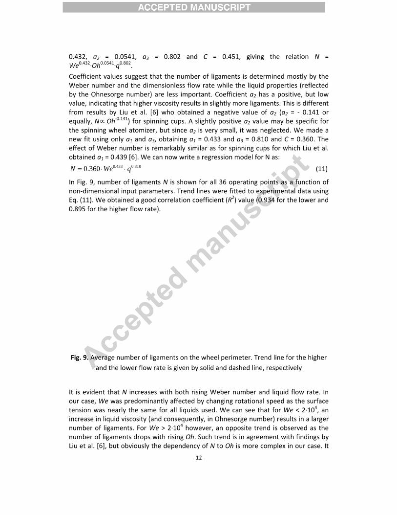
In Fig.non‐dEq. (110.895
Fig. 9
It is evour catensioincreanumbenumbeLiu et
, a2 = 0.032∙Oh0.0541∙q0
cient valuesr number ane Ohnesorgeindicating tresults by Ly, N∝Oh‐0.1
pinning wheeit using onlyof Weber n
ned a1 = 0.43433.0360.0 We⋅
9, number imensional i1). We obtaifor the high
. Average nuand the l
vident that ase, We wason was nearlse in liquid ver of ligameer of ligameal. [6], but o
0541, a3 =0.802.
s suggest thand the dimee number) ahat higher vLiu et al. [6]141) for spinnel atomizer,y a1 and a3, number is re39 [6]. We ca
810.03 q⋅
of ligamentinput paramined a good er flow rate
umber of ligaower flow ra
N increases predominaly the sameviscosity (anents. For Weents drops wobviously th
= 0.802 an
at the numbensionless flare less impviscosity resu] who obtaining cups. A, but since aobtaining a
emarkably sian now write
ts N is showmeters. Trendcorrelation ).
aments on tate is given
with both ntly affected for all liquind consequee > 2∙104 howith rising Ohhe dependen
‐ 12 ‐
nd C = 0
ber of ligamow rate whortant. Coeults in slightlined a negaA slightly posa2 is very sma1 = 0.433 aimilar as fore a regressio
wn for all 36 d lines werecoefficient (
the wheel peby solid and
rising Webed by changinids used. Weently, in Ohnowever, an oh. Such trenncy of N to O
.451, giving
ments is deteile the liquidfficient a2 hly more ligamative value ositive a2 valmall, it was nnd a3 = 0.81r spinning cuon model fo
operating pe fitted to ex(R2) value (0
erimeter. Tre dashed line
er number ang rotationae can see thnesorge numopposite tred is in agreeOh is more c
g the rela
ermined mod propertieshas a positivments. This of a2 (a2 = ue may be sneglected. W10 and C = ups for whicr N as:
points as a fxperimental 0.934 for the
end line for te, respective
and liquid floal speed as that for We <mber) resultsend is obserement with fcomplex in o
ation N =
stly by the s (reflected ve, but low is different ‐ 0.141 or specific for We made a 0.360. The h Liu et al.
(11)
function of data using
e lower and
the higher ely
ow rate. In the surface < 2∙104, an s in a larger rved as the findings by our case. It
‐ 13 ‐
cannot be described well with a simple proportionality N ∝ Oha2, meaning that exclusion of the factor Oha2 from Eq. (7) was justified. At this point however we are not proposing any other model for N(Oh) dependency as a larger Weber number range would be required for this purpose.
It is important to note that in experimental research of liquid disintegration by rotary discs and cups, none of the authors cited have considered the effect of liquid flow rate on the number of ligaments. The same is true for the theoretical equations by Plesset and Whipple (Eq. 2 [4]) and by Kamiya (Eq. 3 [8]). Eisenklam [3] did provide an equation that takes the liquid film thickness (which is proportional to the flow rate) in consideration, but predicted number of ligaments to be only about 20% lower for a thick liquid film compared to a very thin film (for unchanged rotational speed and liquid properties).
However, our results obtained for a spinning wheel indicate a strong, nearly linear dependence of N on the non‐dimensional flow rate (N∝q0.8). The most likely explanation for such significant relationship between q and N is that at higher flow rates and/or nozzle diameters, liquid film width B increases, causing the ligaments to form in several vertical planes along the wheel rotational axis that are parallel to each other, rather than just in one. At the higher flow rate used (i.e., Q = 3.27mL/s), we have in fact observed pairs of ligaments forming very close to each other, but in different planes, especially for the 60% glycerol (the lowest viscosity liquid used). This indicates that liquid film width may be more important than its thickness and that unstable waves also form in the direction transversal to the film (i.e., parallel to the wheel rotational axis), provided it is wide enough (i.e., B >> λm), and the waves are damped by the viscosity. In case of spinning discs and cups, film width at the apparatus lip is constant (equal to the circumference of the latter), but unstable waves can only form on a torus‐shaped outer edge of the film, along the apparatus lip. This is due to the fact that the axis of rotation is perpendicular to the film surface (on a spinning wheel, it is parallel to the film surface).
For the lower flow rate used (i.e., Q = 1.63mL/s), ligaments form in a single plane, thus we can compare the measured number of ligaments to the theoretical models for the number of unstable waves given by Eq. (1), (2) and (3) – Fig. (10).
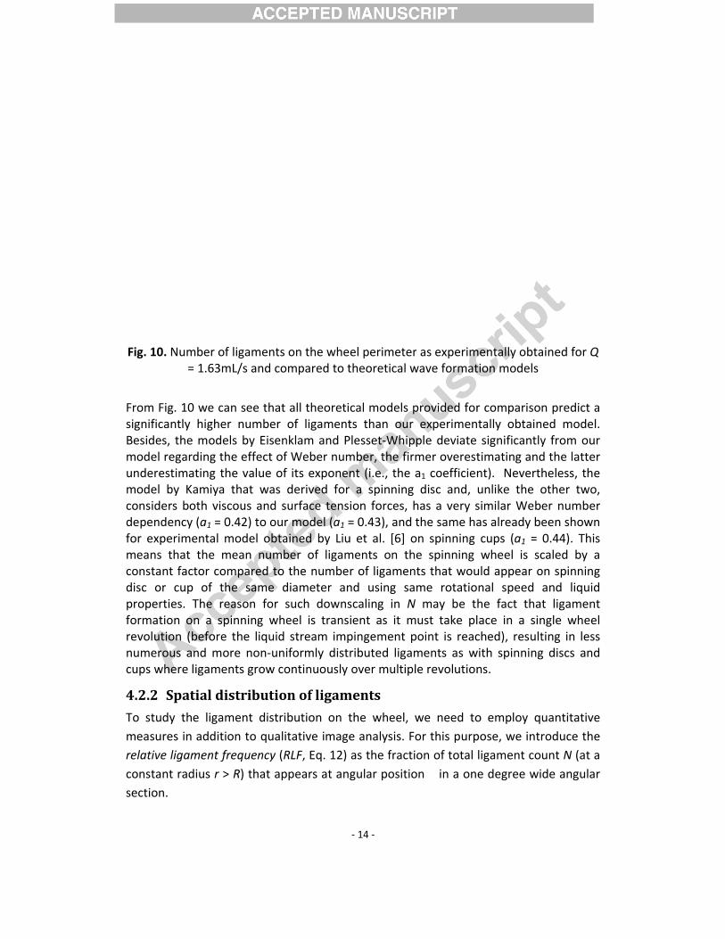
Fig. 10
From significBesidemodelundermodelconsiddepenfor exmeansconstadisc opropeformarevolunumercups w
4.2.2 To stumeasurelativconstasectio
0. Number o= 1.63m
Fig. 10 we ccantly highees, the modl regarding testimating tl by Kamiyaders both visndency (a1 = xperimental s that the mant factor coor cup of trties. The rtion on a sution (beforerous and mwhere ligame
Spatial d
udy the ligaures in additve ligament fant radius r n.
of ligaments mL/s and co
can see that er number els by Eisenthe effect ofthe value ofa that was scous and s0.42) to ourmodel obtamean numbompared to the same dreason for spinning whe the liquid ore non‐unents grow co
distributio
ament distrition to qualifrequency (R> R) that ap
on the wheompared to t
all theoretiof ligamentnklam and Pf Weber numf its exponenderived for urface tensr model (a1 =ained by Liuber of ligamthe numbediameter ansuch downseel is transstream impiformly distrontinuously
on of ligam
bution on titative imageRLF, Eq. 12) ppears at ang
‐ 14 ‐
el perimetertheoretical w
cal models pts than our Plesset‐Whipmber, the firnt (i.e., the a spinningion forces, h= 0.43), and u et al. [6] oments on thr of ligamennd using sascaling in Nient as it mpingement pributed ligaover multip
ments
the wheel, e analysis. Fas the fractgular positio
r as experimwave format
provided forexperimen
pple deviate rmer overesta1 coefficien disc and, has a very sthe same haon spinning he spinning nts that wouame rotatioN may be thmust take plpoint is reacments as wle revolution
we need toFor this purpion of total on � in a on
mentally obtation models
r comparisotally obtainsignificantlytimating andnt). Nevertunlike the osimilar Webas already bcups (a1 = wheel is sc
uld appear onal speed he fact thaace in a sinched), resultwith spinningns.
o employ qpose, we intrligament coe degree wi
ained for Q
n predict a ned model. y from our d the latter heless, the other two, er number een shown 0.44). This caled by a on spinning and liquid t ligament ngle wheel ting in less g discs and
uantitative roduce the unt N (at a de angular
‐ 15 ‐
°°
°+°−=360...0
5.0...5.0
||
),(N
NrRLF ϕϕϕ (12)
Note that all the quantities in Eq. 12 are temporally averaged. The RLF diagrams for r = 1.1R are given in Fig. 11.
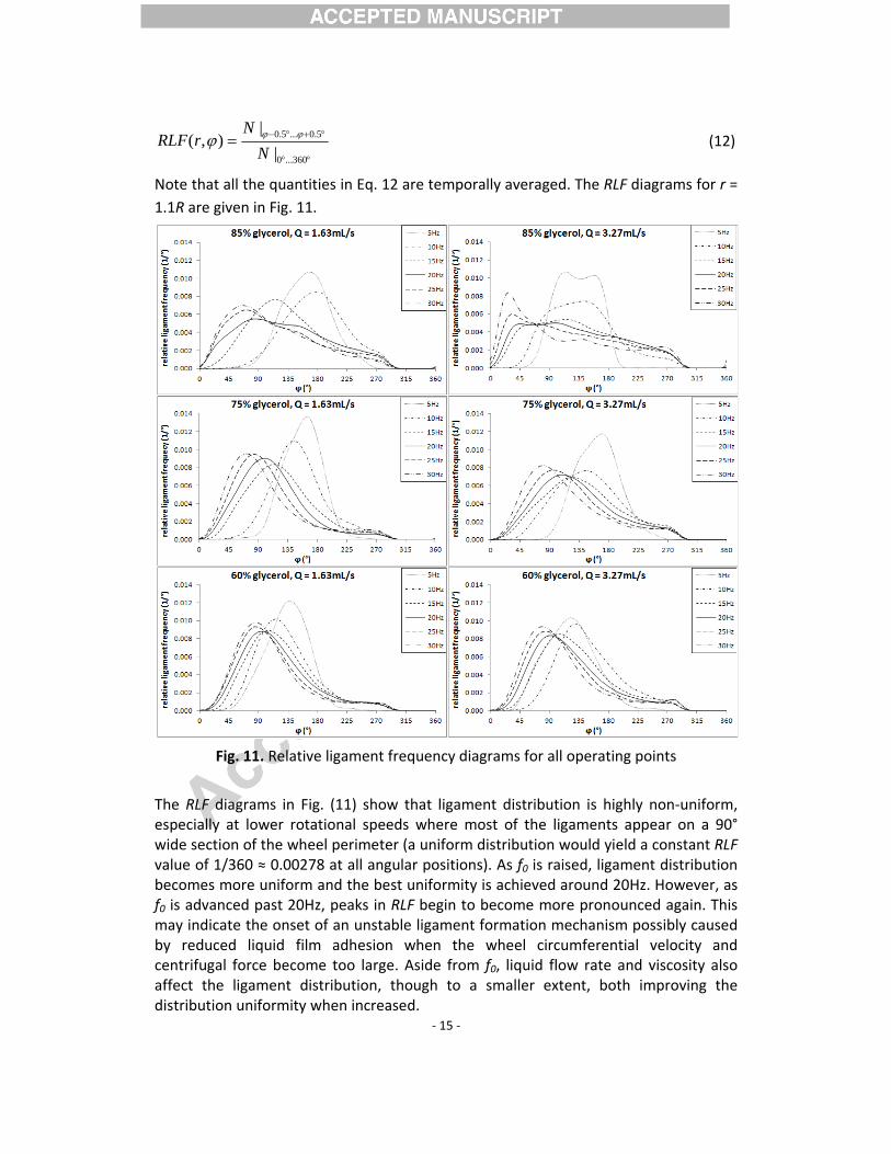
Fig. 11. Relative ligament frequency diagrams for all operating points
The RLF diagrams in Fig. (11) show that ligament distribution is highly non‐uniform, especially at lower rotational speeds where most of the ligaments appear on a 90° wide section of the wheel perimeter (a uniform distribution would yield a constant RLF value of 1/360 ≈ 0.00278 at all angular positions). As f0 is raised, ligament distribution becomes more uniform and the best uniformity is achieved around 20Hz. However, as f0 is advanced past 20Hz, peaks in RLF begin to become more pronounced again. This may indicate the onset of an unstable ligament formation mechanism possibly caused by reduced liquid film adhesion when the wheel circumferential velocity and centrifugal force become too large. Aside from f0, liquid flow rate and viscosity also affect the ligament distribution, though to a smaller extent, both improving the distribution uniformity when increased.
‐ 16 ‐
For all operating points, relative ligament frequency on the liquid film is zero at the liquid stream impingement point (� ≈ 300°) and does not begin to rise until about the wheel 3 o’clock position (� = 0°). The layer of newly supplied liquid is first accelerated to the velocity of the remaining liquid film and then additional time (and consequently, wheel rotation) is required for ligaments to start growing from unstable waves. For this reason, a section of the wheel perimeter (between 60° and 140° in width, depending on the rotational speed and flow rate) after the impingement point is ligament‐free. As already noted, ligament formation at f0 = 5Hz is severely inhibited by combined effects of gravity, surface tension and velocity slip, which is now confirmed by the RLF diagrams. A relatively quick drop in RLF is visible after the peak value which occurs between 135° and 180° depending on operating parameters – lower viscosities result in an earlier suppression of ligament formation. It is interesting that for f0 > 5Hz, the peak in RLF occurs even sooner, but the ligament frequency drops more slowly until the remaining ligaments are eventually cut off by the protective screen shielding the onflowing liquid stream. Unlike spinning discs and cups where liquid is centrally fed, spinning wheels are only supplied with liquid at the impingement point on the mantle surface. The film thins along the wheel perimeter as it gets depleted by the ligaments tearing away from it. We believe such thinning makes formation of new ligaments increasingly difficult, thus resulting in reduction of ligament frequency, especially when the liquid flow rate is low.
For the reasons stated, a spinning wheel produces several times less ligaments than spinning discs and cups when the flow rate is low and the liquid film is narrow (e.g., about 5 times in our case for the flow rate Q = 1.63mL/s, see Fig. 10). However, the liquid film can be made much wider by modifying the supply system to provide a more oval shaped stream of liquid, thus allowing for ligaments to form in multiple planes simultaneously and significantly increasing their number. The maximum flow rate that can properly disintegrate on the wheel is limited, with excessive liquid flow deflecting from its surface soon after the impingement point. In our case, we experimentally determined it to be about 5mL/s for a 3mm circular liquid supply nozzle and 45mm wheel radius, but we estimate it could be up to 50mL/s if film was spread across the whole wheel width, i.e. 50mm. The excessive liquid that is deflected from the wheel can be atomized by adding another wheel where a new liquid film is formed. In industrial systems such as those used for mineral fiber production, up to 4 wheels are used simultaneously [1].
4.2.3 Diameter of ligaments and droplets Apart from mean ligament number and distribution, we also determined the diameter of ligaments (dL), head droplets (dHD) and droplets to which the ligaments disintegrated after the head droplet pinch‐off (d). All of these properties will be shown as a function of the liquid film Weber number which ranged between 1.5∙103 and 6.1∙104. Weber number of the ligaments (WeL = ρ(2πf0R)
2dL/σ) was much lower, ranging between 16 and 238. Ligament Reynolds numbers (ReL = ρ(2πf0R)dL/ μ) were between 7 and 138, meaning that flow was laminar for all operating points. The same applies to droplet
Reynoligame
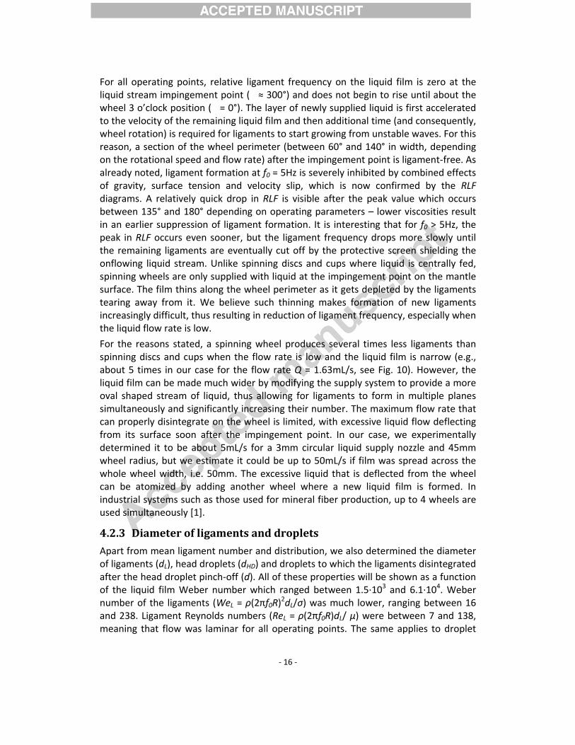
Ligamimagefollow0.151,diamea1 gavmodel
/ RdL
Measushownflow rbetwe0.986)to 0.15
In add(d) to valuesobtainnumbenumbeusing propo
olds numberent diamete
ent diametes for all 36
wing coefficie, suggestingeter. For thisve the value l for dL:
134.0 ⋅= WeRured ligamen in Fig. 12. rate and pheen the prop). Ligament 5mm at 30H
dition to ligawhich the ls of dL. Dataned: a1 = ‐0.er is the mer is also imonly a1 andse a followin
rs which wer (i.e., d/dL o
er just befooperating pents were o that Webes reason we of a1 = ‐0.3
345.0−We
nt diameterIt can be n
hysical propeposed regrediameters raHz.
Fig. 12. Lig
ament diamigaments dia fit was ma.334, a2 = ‐0most significaportant. Ford a2 gave thng regressio
ere higher fror dHD/dL), bu
ore the ligapoints. Dataobtained: a1er number isneglected c
345 and C =
rs along witoted that derties seemssion modeange from a
gament diam
eters, we alsintegratedde analogou0.092, a3 = 0ant paramer this reasone value of an model for
‐ 17 ‐
rom ReL by ut did not ex
ment break fit was ma= ‐0.346, a
s the only scoefficients a0.134 and w
th the propdL drops whem to have litl and the mapproximate
meter before
lso calculateby applyingusly to dL an0.0442 and eter for ligan we neglecta1 = ‐1/3, ad:
the ratio oxceed Re = 6
kup (dL) wade accordina2 = ‐0.0198ignificant paa2 and a3 anwe propose
posed modeen Weber nttle effect oeasured valely 0.5mm at
e disintegrat
ed the meang Eq. (9) andnd the followC = 0.379, sment diameted the coeffa2 = ‐0.093 a
of droplet d600.
s measuredngly to Eq. (8, a3 = 0.046arameter fond a new fit a following
el for dL (Equmber riseson dL. The cues is very t 5Hz rotatio
ion
n diameter od (10) to thewing coefficsuggesting teter while ficient a3 anand C = 0.36
iameter to
d from the 8) and the 61 and C = or ligament using only regression
(13)
. (13)) are s but liquid correlation good (R2 = onal speed
of droplets measured cients were hat Weber Ohnesorge d a new fit 69 and we
/ =RdCalculin Fig.viscossignific(Eq. (9flow rregresand 0.approxmodelWebeprodu(1.42mdecreaatomiz
For thdroplelimit fosimilarbut atslightlyhas bowhich speedefficie
369.0 −⋅= Ohated droplet. 13. It can ity is reduccant as for l9) and (10)) prate seems ssion model .994 for 85%ximately 1.0l (Eq. (14)) wr number race finer dromm…0.77mmase more qzation (d∝W
Fig. 13
e liquid withet diametersor droplet dr trend begit slightly largy reduced aoth lowest sdampens its as this wncy instead
3/1093.0 −− ⋅We
t diameters be noted thced (i.e., atigament diapredict λOPT to have littand the me%, 75% and 0mm at 5Hz with the one ange of Weplets (d = 1.m). Also, in quickly withWe‐1/6 [6]).
3. Diameter
h highest viss become almiameter andns to show ger Weber nt lower viscsurface tenst. Again, it
would not heby causing p
along with that d drops t lower Ohmeters becaand d to inctle effect onasured valu60% glycerorotational sfor spinning
e = 103…105,.15mm…0.2case of spih Weber n
of droplets
scosity (85%most indeped no lower vafor operatinnumbers, indosities. Thision which cdoes not melp to furthpartial sheet
‐ 18 ‐
the proposewhen Webnesorge nuause the equrease with vn dL. The coes is very gool, respectivepeed to 0.3mg cups (Liu e, a spinning5mm) than inning wheenumber (d∝
formed by li
% glycerol), itendent of Walues of d cang points widicating that is probablyauses ligam
make sense ther reduce t formation o
d model for ber number mbers). Liquations usedviscosity. Onorrelation bood, with R2
ely. Droplet mm at 30Hzt al. [6]), weg wheel witha spinning cel atomizatio∝We‐1/3) th
igament disi
t can be seeWe, suggestinan be achievth 75% glyct lowest achy due to the ent breakupto use exced, but coulor even liqu
d (Eq. (14)) rises and wuid viscositd to calculaten the other hetween thevalues of 0.diameters r. By compare determinedh 45mm radcup of the saon, droplet han for spi
ntegration
en that for Wng that thereved regardleserol and Q =hievable drofact that 85p and highesssively highd reduce aid stream de
(14)
are shown when liquid ty is more e d from dL hand, liquid e proposed .970, 0.993 range from rison of our d that for a dius would ame radius diameters nning cup
We > 3∙104, e is a lower ss of We. A = 3.27mL/s oplet size is 5% glycerol st viscosity rotational tomization eflection.
As alrethe finof theoperatthe sawill bevaries valuesmodel
/ RdHD
From droplehead dligame(14) anincrea30Hz. suppli
5 CoLiquidonto tdynamHowev
eady noted nal ligamente total liquting points aame f0, dHD we given as aslightly dep
s are shownl for dHD:
95.1 ⋅= WeR
Fig. 14. D
Fig. 14 it canet diametersdroplet sizeent disintegrnd we get a sing We anConsequened liquid is a
onclusio disintegratthe wheel mmics of liquiver, the act
in the qualitt disintegratid flow ratand we detewas the sama function opending on tn in Fig. 14
45.0−e
Diameter of
n be observes range from is obviouslyration. The proportionad in our cantly, the maalso significa
ons ion was stu
mantle surfacid atomizatitual operatio
tative imageion are quite. Head drrmined it to
me for all floof mean Wethe surface and we pro
f head drople
ed that dHD dm 3.1mm at y much largratio dHD/dality dHD/d ∝se, it rangeass fraction antly lower a
died on a spce. Experimeion are simon is signifi
‐ 19 ‐
e analysis, hee large and oplet diameo only depenow rates andeber numbetension andopose the f
ets that pinc
drops when 5Hz rotationger than thecan be obta
∝We‐0.117. Ths from 3.1 of head drat higher rot
pinning wheental resultsilar to the cantly diffe
ead dropletsmake up foeter (dHD) wnd on the rotd liquid typeer at a certad density of following lea
ch off from t
Weber numnal speed toe size of droained if Eq. his means that 5Hz rotatroplets in thational spee
eel with thes show that other typesrent from a
s that pinchor a significawas measurtational speees. For this rain f0 (Webethe liquid). ast‐squares
the ligament
mber is increao 0.63mm atoplets origin(15) is divid
he ratio decrtional speedhe total maeds.
liquid streathe fundams of rotary atomizers w
off before ant fraction red for all ed while at reason, dHD er number Measured regression
(15)
ts
ased. Head t 30Hz. The ating from ded by Eq. reases with d to 2.0 at ass flow of
am flowing mental fluid atomizers.
with central
‐ 20 ‐
liquid feed such as the spinning discs and cups. On a spinning wheel, there is no direct drop formation, but only ligament formation accompanied by partial sheet formation at higher rotational speeds. Ligaments form transiently and have a non‐uniform spatial distribution around the wheel perimeter. Also, the head droplet pinch‐off phenomenon is present whenever ligament formation occurs, producing relatively large droplets. If the presence of head droplets is undesired (for instance, in fiber production), their mass fraction can be lowered by increasing the rotational speed of the device.
Regression model for dL an d obtained by the least squares fit for measured diameter of ligaments and droplets to which they disintegrate, respectively, are applicable for calculating these properties in a wide range of operating conditions (i.e., 103 < We < 105). The diameter of liquid ligaments as well as droplets decreases with an increase in the rotational speed of the wheel and slightly increases if liquid viscosity is raised. An increase in liquid flow rate causes the number of ligaments to increase, but their diameter remains practically unchanged (the same is true for droplet and head droplet diameters). This indicates the flow rate may be varied in a wide range without the need to adjust other operating parameters. When the liquid stream is shaped properly so that the film is as wide as possible, the maximum attainable flow rate that can be well atomized is several times higher compared to a spinning disc or a spinning cup of the same diameter.
Regarding the wheel rotational speed, the useful operating range is limited by the onset of stable ligament formation on the lower end and by partial sheet formation on the upper end when the latter becomes too pronounced and the liquid film starts to detach from the wheel. An optimal Weber number range for our set‐up can be estimated to 5∙103 < We < 5∙104. However, it is important to note that some other parameters that may be significant for the atomization process, e.g. the wheel diameter, liquid impingement point and the wheel surface roughness were kept constant during our experiment. A modification of existing experimental setup and operating point interval to also vary these parameters could further improve the understanding of spinning wheel atomizer operation.
Acknowledgements
This work is in part supported by Slovenian Research Agency (ARRS), grants P2‐0167, L2‐4270. Operation is also in part financed by the European Union, European Social Fund; Ministry of economic development and technology, Republic of Slovenia, project KROP 2011 at Abelium d.o.o.
‐ 21 ‐
Nomenclature
a1 Weber number exponent obtained by experimental data fit, ‐ a2 Ohnesorge number exponent obtained by experimental data fit, ‐ a3 Dimensionless flow rate exponent obtained by experimental data fit, ‐ B liquid film width on the wheel, m d diameter of droplets formed by ligament disintegration, m dHD head droplet diameter, m dL mean ligament diameter, m dN liquid nozzle diameter, m f0 atomizer wheel rotational speed, Hz = 2π∙rad/s g gravitational acceleration, m/s2 km wave number of the most unstable disturbance (km = 2πR/λm), ‐ N number of ligaments on the wheel perimeter, ‐ Oh Ohnesorge number (Oh = We0.5/Re), ‐ Q liquid volume flow rate, m3/s q liquid dimensionless flow rate (q = Q/ωR³), ‐ R atomizer wheel radius, m r radius in the polar coordinate system, m Re Reynolds number, ‐ RLF Relative ligament frequency along the wheel perimeter, 1/° St Stability number (St = Oh2), ‐ s ligament circumferential spacing on the liquid film, m t time, s We Weber number, ‐ wgl Glycerol mass fraction in a glycerol‐water mixture, ‐ Greek letters λm wavelength of the most unstable (fastest growing) wave on liquid film, m λOPT wavelength of the fastest growing dilatational wave on the ligament, ‐ μ liquid viscosity, Pa∙s ρ liquid density, kg/m3
σ liquid surface tension coefficient, N/m � angle in the polar coordinate system, °
‐ 22 ‐
References
[1] Širok B., Blagojević B., Bullen P.: Mineral Wool: Production and Properties; Woodhead Publishing Limited, Cambridge, 2008.
[2] Taylor G. I. (1950) The Instability of Liquid Surfaces when Accelerated in a Direction Perpendicular to Their Planes. Proceedings of the Royal Society, Vol. 201, No. 1065, pp. 192–196.
[3] Eisenklam P. (1964) On Ligament Formation from Spinning Discs and Cups. Chemical Engineering Science, Vol. 19, No. 9, pp. 693–694.
[4] Plesset M. S., Whipple C. G. (1974) Viscous Effects in Rayleigh‐Taylor Instability. Physics of Fluids, Vol. 17, No. 1, pp. 1–7.
[5] Hinze J. O., Milborn H. (1950) Atomization of Liquids by Means of a Rotating Cup. Journal of Applied Mechanics, Vol. 17, No. 2, pp. 145–153.
[6] Liu J., Yu Q., Guo Q. (2012) Experimental Investigation of Liquid Disintegration by Rotary Cups. Chemical Engineering Science, Vol. 73, pp. 44–50.
[7] Liu J., Yu Q., Li P., Du W. (2012) Cold Experiments on Ligament Formation for Blast Furnace Slag Granulation. Applied Thermal Engineering, Vol. 40, No. 1, 2012, pp. 351–357.
[8] Kamiya T. (1972) Analysis of the Ligament‐Type Disintegration of Thin Liquid Film at the Edge of Rotating Disk. Journal of Chemical Engineering of Japan, Vol. 5, pp. 391–396.
[9] Kamiya T., Kayano A. (1972) Film‐type Disintegration by Rotating Disk. Journal of Chemical Engineering of Japan, Vol.5, pp.174–182.
[10] Lefebvre A.: Atomization and spays; Hemisphere, New York, 1989.
[11] Olesen M: Prediction of drop‐size distributions based on ligament breakup. PhD thesis, Queen's University at Kingston, Kingston, Ontario, Canada, 1997.
[12] Liu H.: Science and Engineering of Droplets: Fundamentals and Applications; Noyes Publications, Norwich, New York, U.S.A., 2000.
[13] Cheng N. S. (2008) Formula For Viscosity of Glycerol‐Water Mixture. Industrial and
Engineering Chemistry Research, vol. 47, no. 9, pp. 3285‐3288.
[14] Physical Properties of Glycerine and Its Solutions, Glycerine Producers' Association, New York, 1963.
[15] Tong A. Y., Wang Z. (2007) Relaxation dynamics of a free elongated liquid ligament. Physics of Fluids, Vol. 19, No. 9, paper No. 092101.
[16] Van Hoeve W., Gekle S., Snoeijer J. H., Versluis M., Brenner M. P., Lohse D. (2010) Breakup of diminutive Rayleigh jets. Physics of Fluids, Vol. 22, No. 12, paper No. 122003.
‐ 23 ‐
Highlights of the paper
• Liquid disintegration on a spinning wheel atomizer was investigated experimentally.
• Ligament formation mode is predominant, no direct drop or complete sheet formation.
• Number of ligaments is proportional to the liquid flow rate and Weber number. • Ligaments form transiently and have a non-uniform spatial distribution on the
wheel. • Droplet size distribution is bimodal due to head droplet pinch-off.