Embed Size (px)
Citation preview
SDG Construction Technology Ltd. 21 Tullygoonigan Industrial Est., Moy Road, Armagh, BT61 8DRTel: +44 (0)28 37528 999 | Fax: +44 (0)28 37528 928 | Email: [email protected] | Web: www.sdg.ie
1
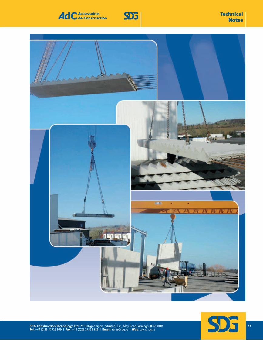
LIFTING WITH SPHERICAL ANCHOR SYSTEMS

SDG Construction Technology Ltd. 21 Tullygoonigan Industrial Est., Moy Road, Armagh, BT61 8DRTel: +44 (0)28 37528 999 | Fax: +44 (0)28 37528 928 | Email: [email protected] | Web: www.sdg.ie
2
SUMMARYPage
List of products 2
1. Sizing Methods 121.1. Design process 121.2. Drawing of the Precast element and expected lifting process 121.3. Weight of the element (P) 121.4. Formwork adhesion at the removal from the mould (A) 131.5. Location and determination of the number of efficient lifting points (n) 131.6. Sling angle and multiplication coefficient (Ce) 151.7. Lifting and handling dynamic coefficient (Cd) 151.8. Resultant load by lifting point (F) 151.9. Concrete resistance (fck) 16
2. Choice of the anchor 1619
2.2. Double head anchor 252.3. Eye anchor 262.4. Foot & eye anchor 272.5. Rebar anchor 282.6. Plate anchor 29
3. Choice of the former 303.1. Formers for lift head anchors, eye anchors, and foot & eye anchors 323.2. Additional accessories for formers 343.3. Formers for double head anchors 35
4. Lifting eye 364.1. Quality system 364.2. Periodic control 374.3. Remote decoupling 37
5. Use and safety conditions 37
Accessoires de Construction1 rue Jacques Robert 95500 LE THILLAYFRANCE
Page 2LAH - Octobre 2013
Tel : +33 1 39 33 18 60Fax : +33 1 39 88 14 42
E-mail : [email protected]
2.1. Lift head anchor
Tel: +44 (0)28 37528 999 | Email: [email protected] | Web: www.sdg.ie
SDG Construction Technology Ltd. 21 Tullygoonigan Industrial Est., Moy Road, Armagh, BT61 8DRTel: +44 (0)28 37528 999 | Fax: +44 (0)28 37528 928 | Email: [email protected] | Web: www.sdg.ie
3
Accessories LIFTING
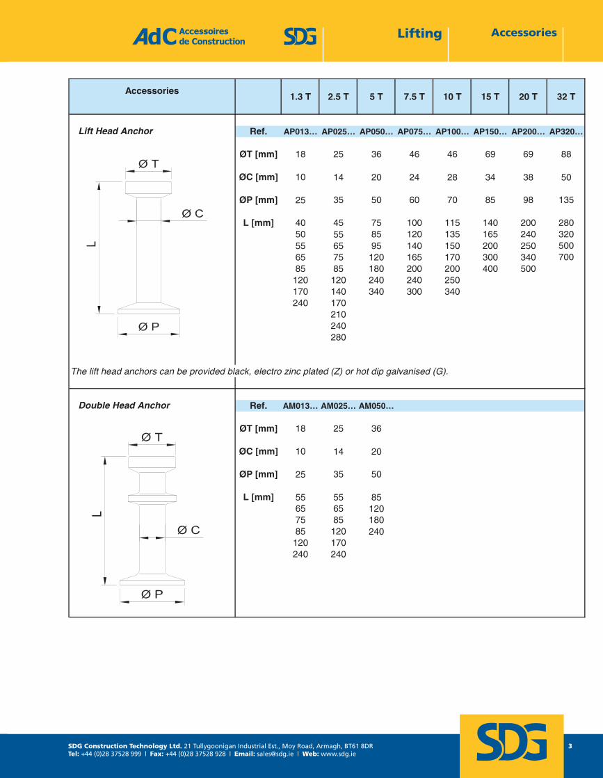
Accessories1.3 T 2.5 T 5 T 7.5 T 10 T 15 T 20 T 32 T
Ref. AP013… AP025… AP050… AP075… AP100… AP150… AP200… AP320…
ØT [mm] 18 25 36 46 46 69 69 88
ØC [mm] 10 14 20 24 28 34 38 50
ØP [mm] 25 35 50 60 70 85 98 135
L [mm] 40 45 75 100 115 140 200 28050 55 85 120 135 165 240 32055 65 95 140 150 200 250 50065 75 120 165 170 300 340 70085 85 180 200 200 400 500120 120 240 240 250170 140 340 300 340240 170
210240280
The lift head anchors can be provided black, electro zinc plated (Z) or hot dip galvanised (G).
Ref. AM013… AM025… AM050…
ØT [mm] 18 25 36
ØC [mm] 10 14 20
ØP [mm] 25 35 50
L [mm] 55 55 8565 65 12075 85 18085 120 240120 170240 240
Lift Head Anchor
Double Head Anchor
Accessoires de Construction1 rue Jacques Robert 95500 LE THILLAYFRANCE
Page 3LAH - Octobre 2013
Tel : +33 1 39 33 18 60Fax : +33 1 39 88 14 42
E-mail : [email protected]
AccessoriesLifting
SDG Construction Technology Ltd. 21 Tullygoonigan Industrial Est., Moy Road, Armagh, BT61 8DRTel: +44 (0)28 37528 999 | Fax: +44 (0)28 37528 928 | Email: [email protected] | Web: www.sdg.ie
4
Accessories LiftingAccessoiresaccessories LIFTING
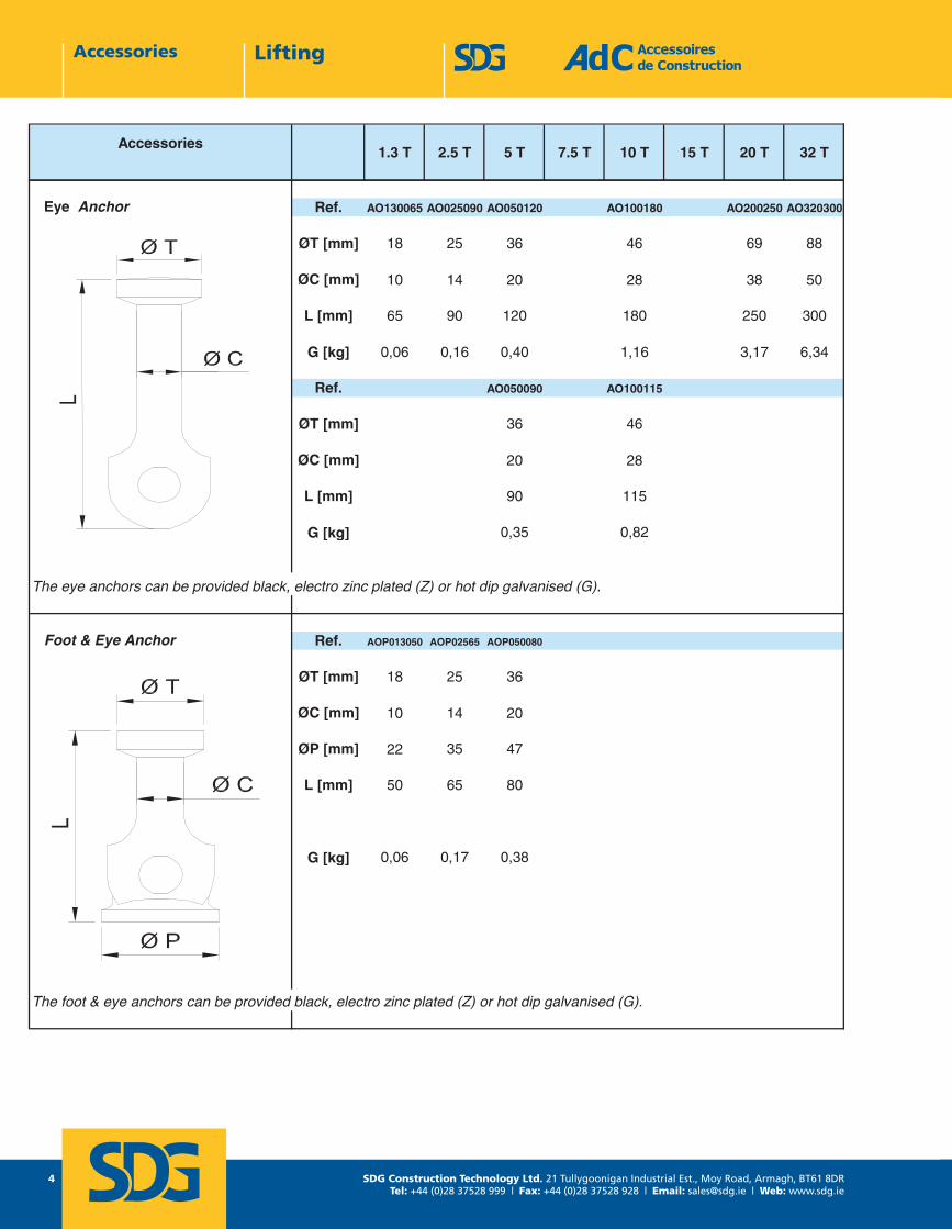
Accessories1.3 T 2.5 T 5 T 7.5 T 10 T 15 T 20 T 32 T
Ref. AO130065 AO025090 AO050120 AO100180 AO200250 AO320300
ØT [mm] 18 25 36 46 69 88
ØC [mm] 10 14 20 28 38 50
L [mm] 65 90 120 180 250 300
G [kg] 0,06 0,16 0,40 1,16 3,17 6,34
Ref. AO050090 AO100115
ØT [mm] 36 46
ØC [mm] 20 28
L [mm] 90 115
G [kg] 0,35 0,82
The eye anchors can be provided black, electro zinc plated (Z) or hot dip galvanised (G).
Ref. AOP013050 AOP02565 AOP050080
ØT [mm] 18 25 36
ØC [mm] 10 14 20
ØP [mm] 22 35 47
L [mm] 50 65 80
G [kg] 0,06 0,17 0,38
The foot & eye anchors can be provided black, electro zinc plated (Z) or hot dip galvanised (G).
Eye Anchor
Foot & Eye Anchor
Accessoires de Construction1 rue Jacques Robert 95500 LE THILLAYFRANCE
Page 4LAH - Octobre 2013
Tel : +33 1 39 33 18 60Fax : +33 1 39 88 14 42
E-mail : [email protected]
SDG Construction Technology Ltd. 21 Tullygoonigan Industrial Est., Moy Road, Armagh, BT61 8DRTel: +44 (0)28 37528 999 | Fax: +44 (0)28 37528 928 | Email: [email protected] | Web: www.sdg.ie
5
AccessoriesLiftingAccessoiresaccessories LIFTING
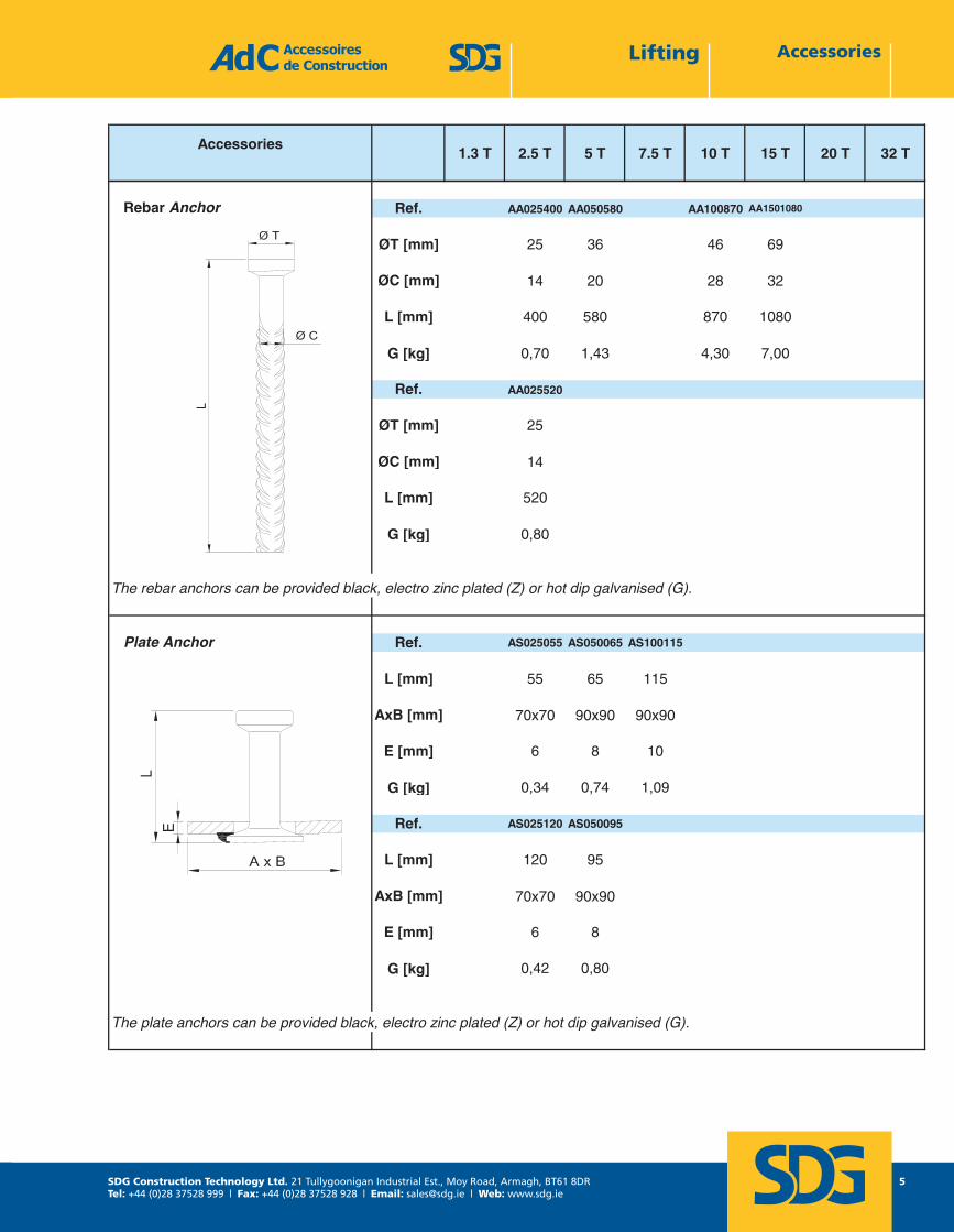
Accessories1.3 T 2.5 T 5 T 7.5 T 10 T 15 T 20 T 32 T
Ref. AA025400 AA050580 AA100870 AA1501080
ØT [mm] 25 36 46 69
ØC [mm] 14 20 28 32
L [mm] 400 580 870 1080
G [kg] 0,70 1,43 4,30 7,00
Ref. AA025520
ØT [mm] 25
ØC [mm] 14
L [mm] 520
G [kg] 0,80
The rebar anchors can be provided black, electro zinc plated (Z) or hot dip galvanised (G).
Ref. AS025055 AS050065 AS100115
L [mm] 55 65 115
AxB [mm] 70x70 90x90 90x90
E [mm] 6 8 10
G [kg] 0,34 0,74 1,09
Ref. AS025120 AS050095
L [mm] 120 95
AxB [mm] 70x70 90x90
E [mm] 6 8
G [kg] 0,42 0,80
The plate anchors can be provided black, electro zinc plated (Z) or hot dip galvanised (G).
Rebar Anchor
Plate Anchor
Accessoires de Construction1 rue Jacques Robert 95500 LE THILLAYFRANCE
Page 5LAH - Octobre 2013
Tel : +33 1 39 33 18 60Fax : +33 1 39 88 14 42
E-mail : [email protected]
SDG Construction Technology Ltd. 21 Tullygoonigan Industrial Est., Moy Road, Armagh, BT61 8DRTel: +44 (0)28 37528 999 | Fax: +44 (0)28 37528 928 | Email: [email protected] | Web: www.sdg.ie
6
Accessories LiftingAccessoiresaccessories LIFTING
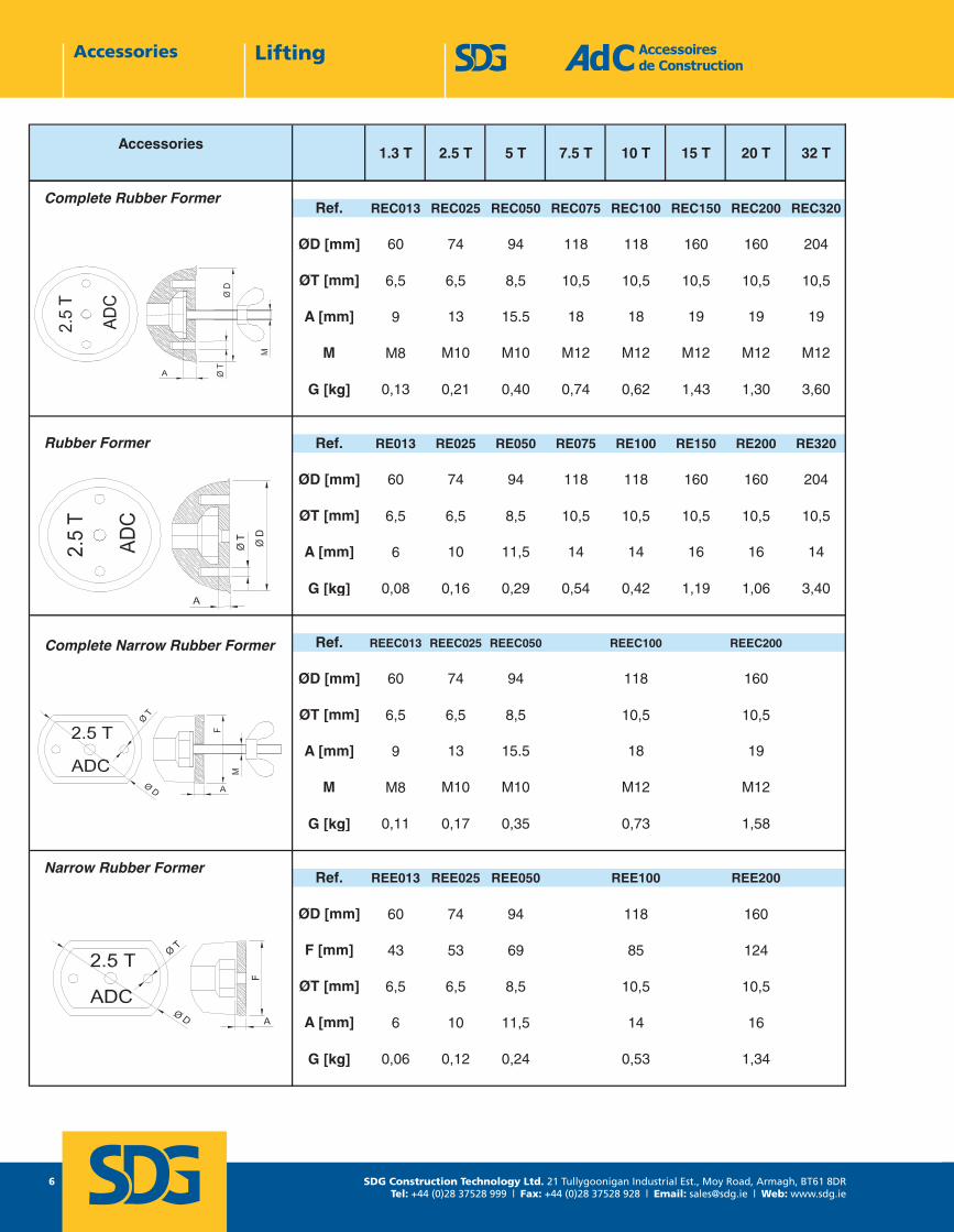
Accessories1.3 T 2.5 T 5 T 7.5 T 10 T 15 T 20 T 32 T
Ref. REC013 REC025 REC050 REC075 REC100 REC150 REC200 REC320
ØD [mm] 60 74 94 118 118 160 160 204
ØT [mm] 6,5 6,5 8,5 10,5 10,5 10,5 10,5 10,5
A [mm] 9 13 15.5 18 18 19 19 19
M M8 M10 M10 M12 M12 M12 M12 M12
G [kg] 0,13 0,21 0,40 0,74 0,62 1,43 1,30 3,60
Ref. RE013 RE025 RE050 RE075 RE100 RE150 RE200 RE320
ØD [mm] 60 74 94 118 118 160 160 204
ØT [mm] 6,5 6,5 8,5 10,5 10,5 10,5 10,5 10,5
A [mm] 6 10 11,5 14 14 16 16 14
G [kg] 0,08 0,16 0,29 0,54 0,42 1,19 1,06 3,40
Ref. REEC013 REEC025 REEC050 REEC100 REEC200
ØD [mm] 60 74 94 118 160
ØT [mm] 6,5 6,5 8,5 10,5 10,5
A [mm] 9 13 15.5 18 19
M M8 M10 M10 M12 M12
G [kg] 0,11 0,17 0,35 0,73 1,58
Ref. REE013 REE025 REE050 REE100 REE200
ØD [mm] 60 74 94 118 160
F [mm] 43 53 69 85 124
ØT [mm] 6,5 6,5 8,5 10,5 10,5
A [mm] 6 10 11,5 14 16
G [kg] 0,06 0,12 0,24 0,53 1,34
Complete Rubber Former
Rubber Former
Complete Narrow Rubber Former
Narrow Rubber Former
Accessoires de Construction1 rue Jacques Robert 95500 LE THILLAYFRANCE
Page 6LAH - Octobre 2013
Tel : +33 1 39 33 18 60Fax : +33 1 39 88 14 42
E-mail : [email protected]
SDG Construction Technology Ltd. 21 Tullygoonigan Industrial Est., Moy Road, Armagh, BT61 8DRTel: +44 (0)28 37528 999 | Fax: +44 (0)28 37528 928 | Email: [email protected] | Web: www.sdg.ie
7
AccessoriesLiftingAccessoiresaccessories LIFTING
Accessories1.3 T 2.5 T 5 T 7.5 T 10 T 15 T 20 T 32 T
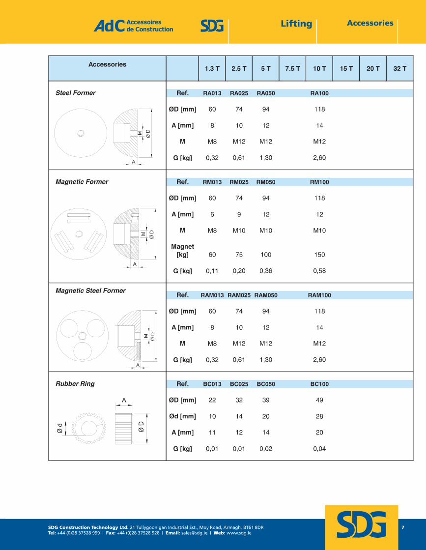
Ref. RA013 RA025 RA050 RA100
ØD [mm] 60 74 94 118
A [mm] 8 10 12 14
M M8 M12 M12 M12
G [kg] 0,32 0,61 1,30 2,60
Ref. RM013 RM025 RM050 RM100
ØD [mm] 60 74 94 118
A [mm] 6 9 12 12
M M8 M10 M10 M10
Magnet[kg] 60 75 100 150
G [kg] 0,11 0,20 0,36 0,58
Ref. RAM013 RAM025 RAM050 RAM100
ØD [mm] 60 74 94 118
A [mm] 8 10 12 14
M M8 M12 M12 M12
G [kg] 0,32 0,61 1,30 2,60
Ref. BC013 BC025 BC050 BC100
ØD [mm] 22 32 39 49
Ød [mm] 10 14 20 28
A [mm] 11 12 14 20
G [kg] 0,01 0,01 0,02 0,04
Steel Former
Magnetic Former
Rubber Ring
Magnetic Steel Former
Accessoires de Construction1 rue Jacques Robert 95500 LE THILLAYFRANCE
Page 7LAH - Octobre 2013
Tel : +33 1 39 33 18 60Fax : +33 1 39 88 14 42
E-mail : [email protected]
SDG Construction Technology Ltd. 21 Tullygoonigan Industrial Est., Moy Road, Armagh, BT61 8DRTel: +44 (0)28 37528 999 | Fax: +44 (0)28 37528 928 | Email: [email protected] | Web: www.sdg.ie
8
Accessories LiftingAccessoiresaccessories LIFTING
AccessorIes1.3 T 2.5 T 5 T 7.5 T 10 T 15 T 20 T 32 T
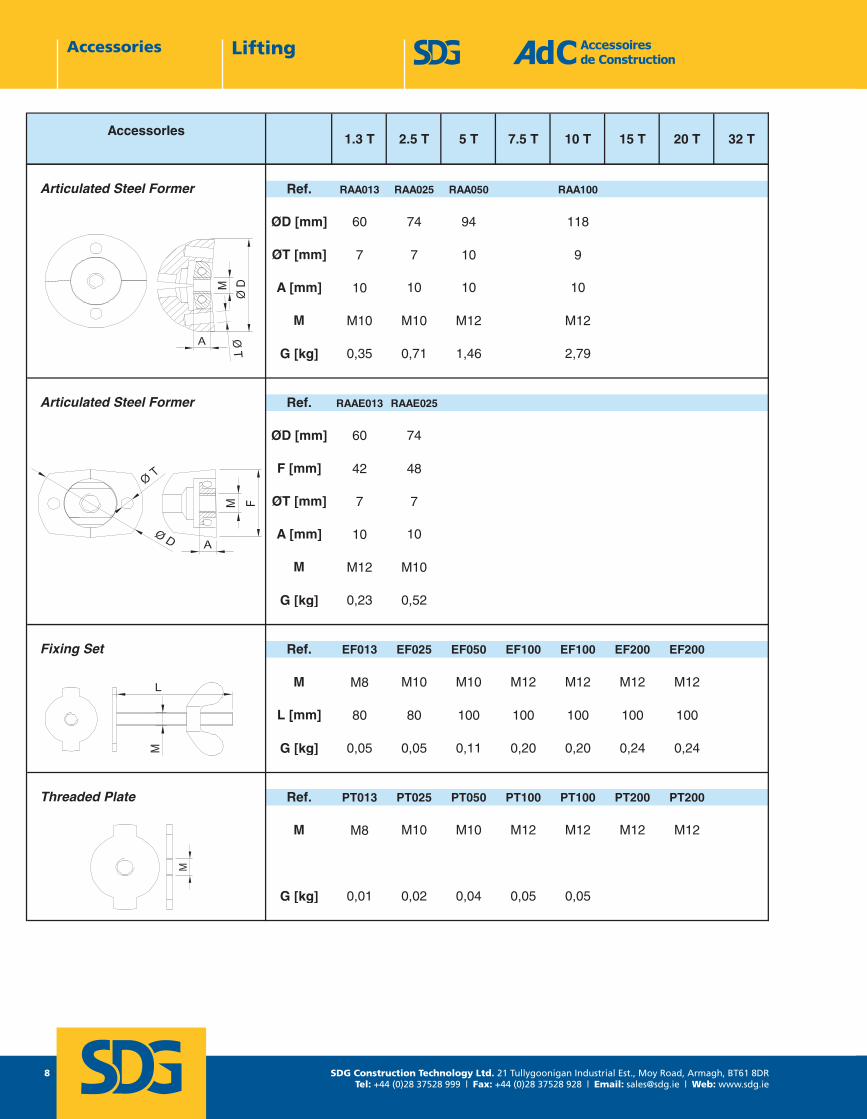
Ref. RAA013 RAA025 RAA050 RAA100
ØD [mm] 60 74 94 118
ØT [mm] 7 7 10 9
A [mm] 10 10 10 10
M M10 M10 M12 M12
G [kg] 0,35 0,71 1,46 2,79
Ref. RAAE013 RAAE025
ØD [mm] 60 74
F [mm] 42 48
ØT [mm] 7 7
A [mm] 10 10
M M12 M10
G [kg] 0,23 0,52
Ref. EF013 EF025 EF050 EF100 EF100 EF200 EF200
M M8 M10 M10 M12 M12 M12 M12
L [mm] 80 80 100 100 100 100 100
G [kg] 0,05 0,05 0,11 0,20 0,20 0,24 0,24
Ref. PT013 PT025 PT050 PT100 PT100 PT200 PT200
M M8 M10 M10 M12 M12 M12 M12
G [kg] 0,01 0,02 0,04 0,05 0,05
Fixing Set
Threaded Plate
Articulated Steel Former
Articulated Steel Former
Accessoires de Construction1 rue Jacques Robert 95500 LE THILLAYFRANCE
Page 8LAH - Octobre 2013
Tel : +33 1 39 33 18 60Fax : +33 1 39 88 14 42
E-mail : [email protected]
SDG Construction Technology Ltd. 21 Tullygoonigan Industrial Est., Moy Road, Armagh, BT61 8DRTel: +44 (0)28 37528 999 | Fax: +44 (0)28 37528 928 | Email: [email protected] | Web: www.sdg.ie
9
AccessoriesLiftingAccessoiresaccessories LIFTING
AccessorIes1.3 T 2.5 T 5 T 7.5 T 10 T 15 T 20 T 32 T
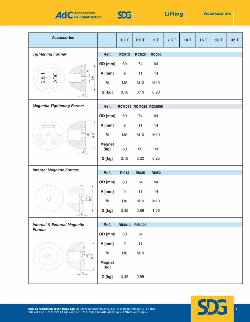
Ref. RC013 RC025 RC050
ØD [mm] 60 74 94
A [mm] 9 11 14
M M8 M10 M10
G [kg] 0,10 0,19 0,23
Ref. RCM013 RCM025 RCM050
ØD [mm] 60 74 94
A [mm] 9 11 14
M M8 M10 M10
Magnet[kg] 60 60 100
G [kg] 0,15 0,20 0,25
Ref. RI013 RI025 RI050
ØD [mm] 60 74 94
A [mm] 9 11 14
M M8 M10 M10
G [kg] 0,45 0,88 1,60
Ref. RIM013 RIM025
ØD [mm] 60 74
A [mm] 9 11
M M8 M10
Magnet[kg]
G [kg] 0,45 0,88
Tightening Former
Magnetic Tightening Former
Internal Magnetic Former
Internal & External Magnetic Former
Accessoires de Construction1 rue Jacques Robert 95500 LE THILLAYFRANCE
Page 9LAH - Octobre 2013
Tel : +33 1 39 33 18 60Fax : +33 1 39 88 14 42
E-mail : [email protected]
SDG Construction Technology Ltd. 21 Tullygoonigan Industrial Est., Moy Road, Armagh, BT61 8DRTel: +44 (0)28 37528 999 | Fax: +44 (0)28 37528 928 | Email: [email protected] | Web: www.sdg.ie
10
Accessories LiftingAccessoiresaccessories LIFTING
Accessories1.3 T 2.5 T 5 T 7.5 T 10 T 15 T 20 T 32 T
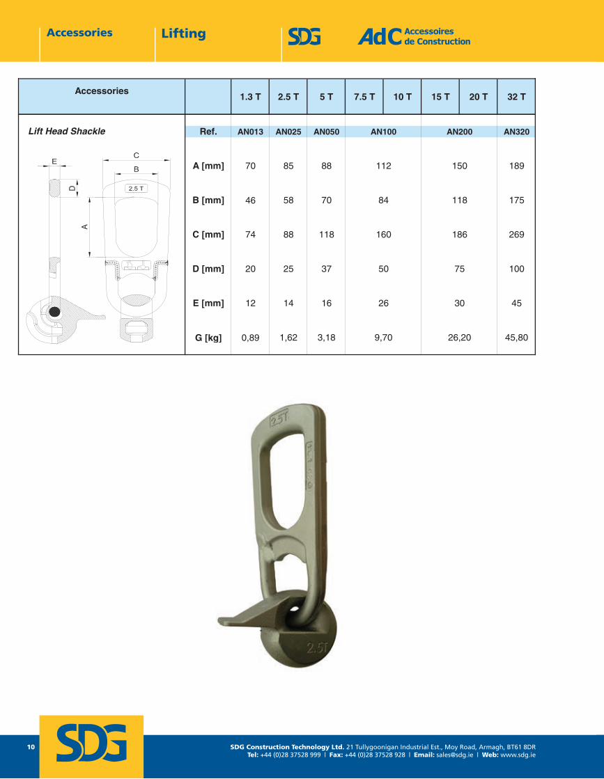
Ref. AN013 AN025 AN050 AN320
A [mm] 70 85 88 189
B [mm] 46 58 70 175
C [mm] 74 88 118 269
D [mm] 20 25 37 100
E [mm] 12 14 16 45
G [kg] 0,89 1,62 3,18 45,80
Lift Head Shackle
9,70 26,20
30
AN200
26
150
118
186
75
AN100
112
84
160
50
Accessoires de Construction1 rue Jacques Robert 95500 LE THILLAYFRANCE
Page 10LAH - Octobre 2013
Tel : +33 1 39 33 18 60Fax : +33 1 39 88 14 42
E-mail : [email protected]
SDG Construction Technology Ltd. 21 Tullygoonigan Industrial Est., Moy Road, Armagh, BT61 8DRTel: +44 (0)28 37528 999 | Fax: +44 (0)28 37528 928 | Email: [email protected] | Web: www.sdg.ie
11
TechnicalNotes
SDG Construction Technology Ltd. 21 Tullygoonigan Industrial Est., Moy Road, Armagh, BT61 8DRTel: +44 (0)28 37528 999 | Fax: +44 (0)28 37528 928 | Email: [email protected] | Web: www.sdg.ie
12
Sizing Methods
noitcurtsnoC ed seriosseccA Tel : +33 1 39 33 18 60 1 rue Jacques Robert Fax : +33 1 39 88 14 42 95500 LE THILLAY moc.sas-cda@cda : liam-E 21 egaPFRANCE moc.sas-cda.www 3102 erbotcO - HAL
1. DESIGN PROCESS
The aim of this design process is the evaluation of the load on cemented anchors in reinforced Precast concrete in order to select the appropriate anchor.
This method is based on the most common applications. If you have any doubt on the application, the assumptions or any points mentioned in this document, you should contact the SDG technical department.
It is also essential that the assumptions are clearly communicated to the organizations tasked with the handling and lifting operations, to ensure that the assumptions are representative of the actual handling and lifting conditions.
1.1. Calculation assumptions
To define the force on the lifting anchors, all of the following points must be considered:
• The technical drawing of the Precast element and the mechanics of handling • The weight of the element (and of the formwork and other accessories lifted with the element) • The formwork adhesion at the removal from the mould • The number of efficient lifting points (and not the number of actual lifting points) • The sling angle • The dynamic coefficient (lifting machinery)
To define the correct anchor to use (type, length, size) it is also necessary to know:
• The concrete resistance when the element is lifted
It is also necessary to distinguish between the handling of the element in the precast factory and on the construction site. All the calculations have to be done in both cases.
All these points are detailed in the following paragraphs.
1.2. Drawing of the Precast element and expected lifting process
Firstly, the technical drawing of the element has to be considered, and the means by which it is to be handled. It is necessary to distinguish between the handling in the precast factory and on site.
1.3. Weight of the Element (P)
The actual weight of the element must be considered. It includes in particular:
• The weight of the concrete element (volume x density). The reinforced concrete density is equal to 2500 daN/m3 (or 25 kN/m3) in general.
• The weight of the formwork and accessories lifted with the element.
SDG Construction Technology Ltd. 21 Tullygoonigan Industrial Est., Moy Road, Armagh, BT61 8DRTel: +44 (0)28 37528 999 | Fax: +44 (0)28 37528 928 | Email: [email protected] | Web: www.sdg.ie
13
noitcurtsnoC ed seriosseccA Tel : +33 1 39 33 18 60 1 rue Jacques Robert Fax : +33 1 39 88 14 42 95500 LE THILLAY moc.sas-cda@cda : liam-E 31 egaPFRANCE moc.sas-cda.www 3102 erbotcO - HAL
1.4. Formwork adhesion at the removal from the mould (A)
The adhesion will depend on 2 factors:
• The surface area of the element in contact with the formwork (S in m²) All the surfaces in contact with the formwork need to be considered, included inclined surfaces.
• The surface condition of the mould. This surface condition is defined by an adhesion factor (qadh in daN/m²)
This force is to be considered at the removal of the element from the mould.
Adhesion factor qadhOiled steel mould, Plywood coated with oiled plastic 100 daN/m²
Varnished oiled wooden mould 200 daN/m² Coarse oiled wooden mould 300 daN/m² Polyurethane matrix Consult the matrix supplier
The adhesion force is: A = qadh x S
This adhesion force must be added to the element weight in order to calculate the force required for lifting purposes.
In some cases, the adhesion force can be zero if the concrete is not in contact with the mould (for pre-stressing beam for example).
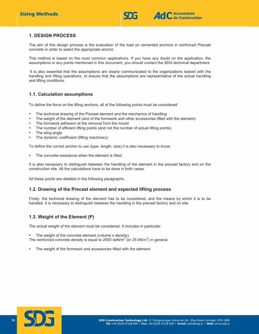
1.5. Location and determination of the number of efficient lifting points (n)
Set up the lifting points symmetrically to the centre of gravity.
Here are some examples of location of lifting points:
Slab Beam
Panel Pipe
Sizing Methods
SDG Construction Technology Ltd. 21 Tullygoonigan Industrial Est., Moy Road, Armagh, BT61 8DRTel: +44 (0)28 37528 999 | Fax: +44 (0)28 37528 928 | Email: [email protected] | Web: www.sdg.ie
14
noitcurtsnoC ed seriosseccA Tel : +33 1 39 33 18 60 1 rue Jacques Robert Fax : +33 1 39 88 14 42 95500 LE THILLAY moc.sas-cda@cda : liam-E 41 egaPFRANCE moc.sas-cda.www 3102 erbotcO - HAL
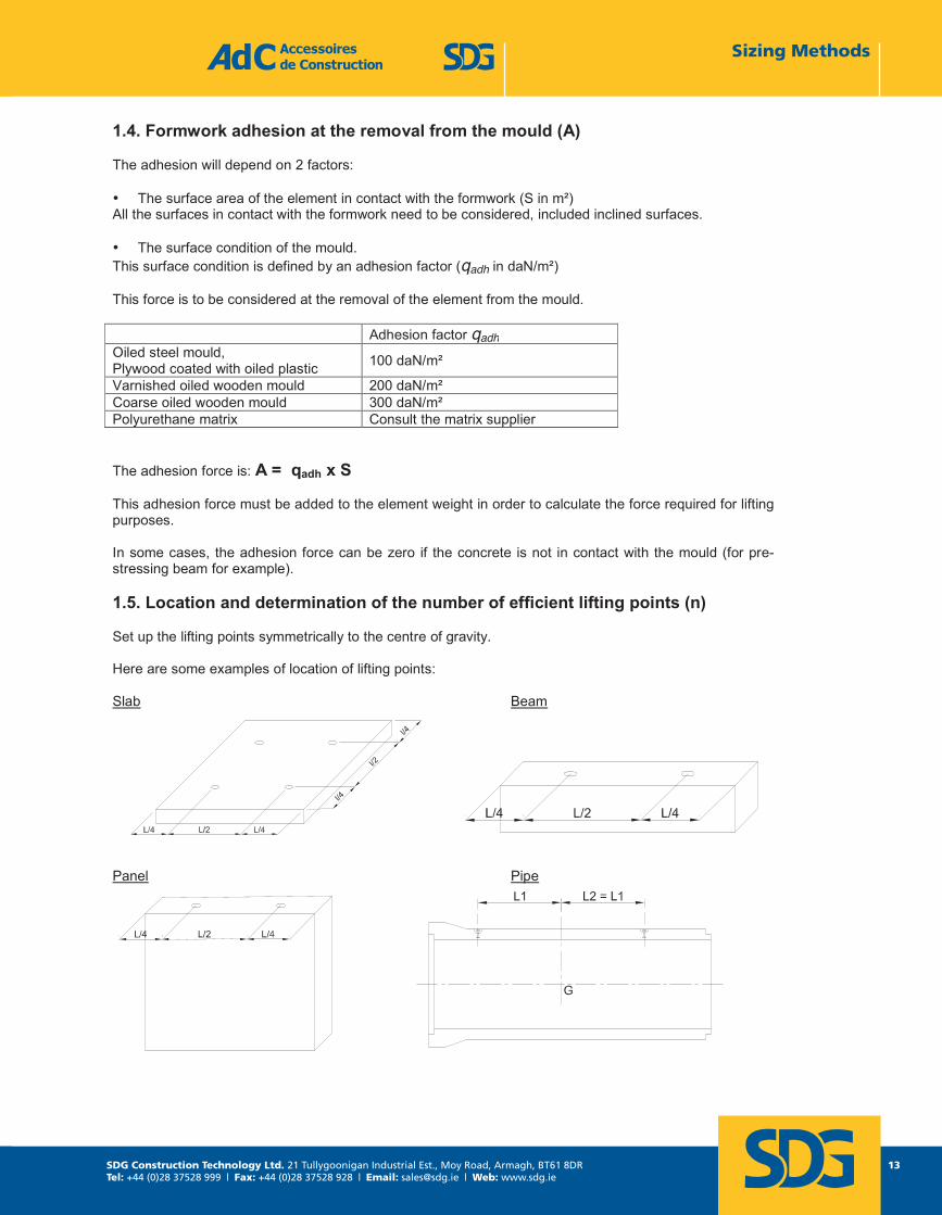
Rotation piece
It is possible that some lifting positions are not appropriate for selected anchor types (see section 2). In particular, minimum distances between lifting points and minimum distances from the edges of the concrete have to be maintained. A minimum encapsulation may be required.
Based on the number of apparent lifting points and the use or otherwise of a balanced lifting system (such as a lifting beam), the number of efficient lifting points is defined as follows:
Efficient lifting points number (n)
Apparent lifting points With a balanced system Others lifting means
4 4 2 3 3 2 2 2 2
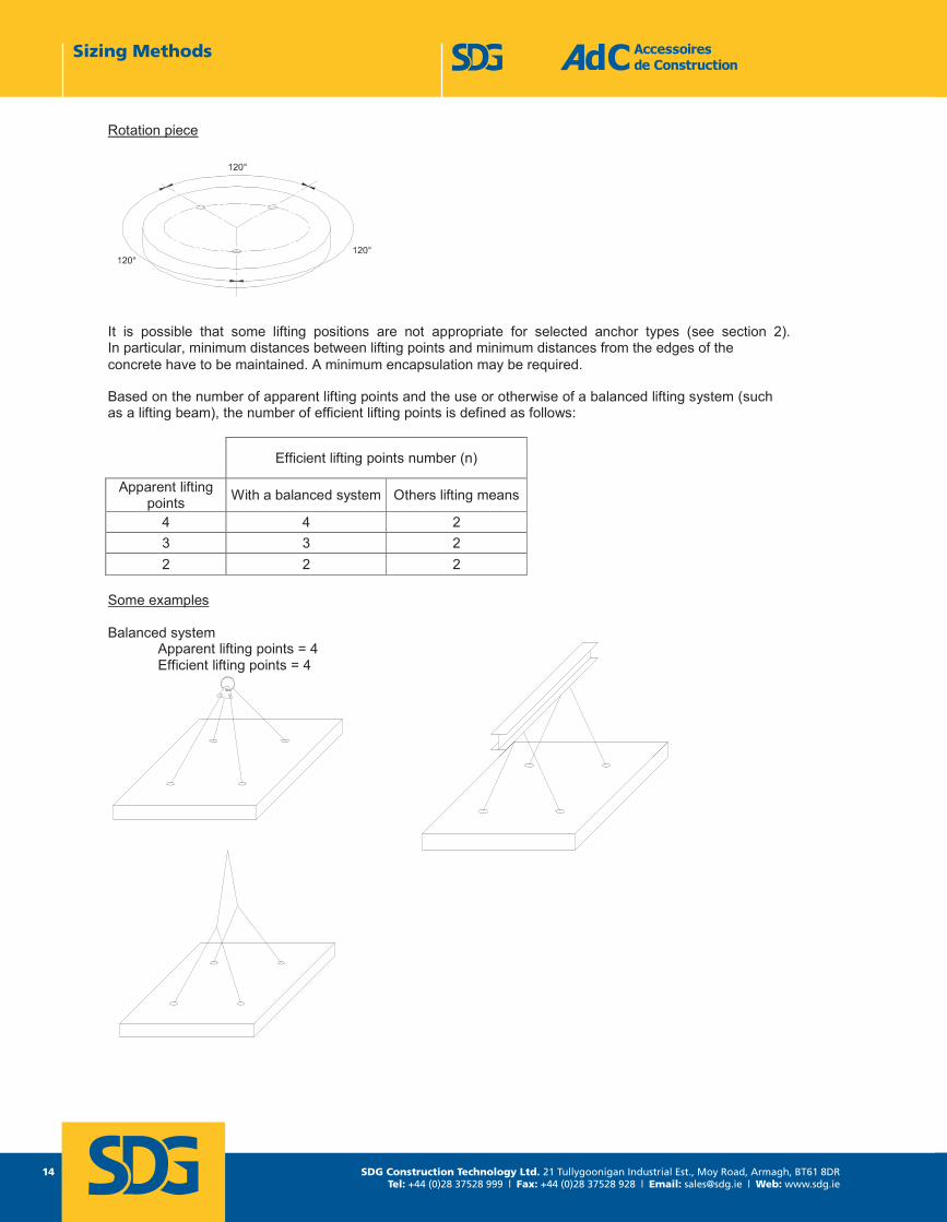
Some examples
Balanced system Apparent lifting points = 4 Efficient lifting points = 4
Sizing Methods
SDG Construction Technology Ltd. 21 Tullygoonigan Industrial Est., Moy Road, Armagh, BT61 8DRTel: +44 (0)28 37528 999 | Fax: +44 (0)28 37528 928 | Email: [email protected] | Web: www.sdg.ie
15
Accessoires de Construction Tel : +33 1 39 33 18 60 1 rue Jacques Robert Fax : +33 1 39 88 14 42 95500 LE THILLAY Page 15 E-mail : [email protected] FRANCE LAH - Octobre 2013 www.adc-sas.com
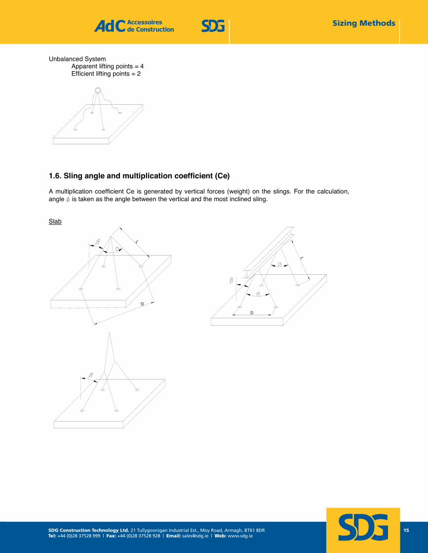
Unbalanced System Apparent lifting points = 4 Efficient lifting points = 2
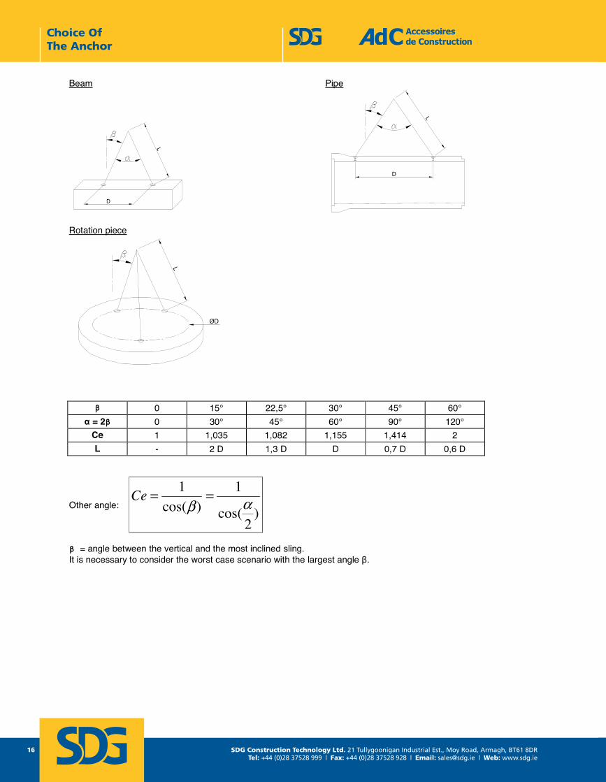
1.6. Sling angle and multiplication coefficient (Ce)
A multiplication coefficient Ce is generated by vertical forces (weight) on the slings. For the calculation, angle β is taken as the angle between the vertical and the most inclined sling.
Slab
Sizing Methods
SDG Construction Technology Ltd. 21 Tullygoonigan Industrial Est., Moy Road, Armagh, BT61 8DRTel: +44 (0)28 37528 999 | Fax: +44 (0)28 37528 928 | Email: [email protected] | Web: www.sdg.ie
16
Accessoires de Construction Tel : +33 1 39 33 18 60 1 rue Jacques Robert Fax : +33 1 39 88 14 42 95500 LE THILLAY Page 16 E-mail : [email protected] FRANCE LAH - Octobre 2013 www.adc-sas.com
Beam Pipe
Rotation piece
β 0 15° 22,5° 30° 45° 60° α = 2β 0 30° 45° 60° 90° 120°
Ce 1 1,035 1,082 1,155 1,414 2 L - 2 D 1,3 D D 0,7 D 0,6 D
Other angle: )
2cos(
1)cos(
1αβ
==Ce
β = angle between the vertical and the most inclined sling. It is necessary to consider the worst case scenario with the largest angle β.
Choice Of The Anchor
SDG Construction Technology Ltd. 21 Tullygoonigan Industrial Est., Moy Road, Armagh, BT61 8DRTel: +44 (0)28 37528 999 | Fax: +44 (0)28 37528 928 | Email: [email protected] | Web: www.sdg.ie
17
Choice Of The Anchor
Accessoires de Construction Tel : +33 1 39 33 18 60 1 rue Jacques Robert Fax : +33 1 39 88 14 42 95500 LE THILLAY Page 17 E-mail : [email protected] FRANCE LAH - Octobre 2013 www.adc-sas.com
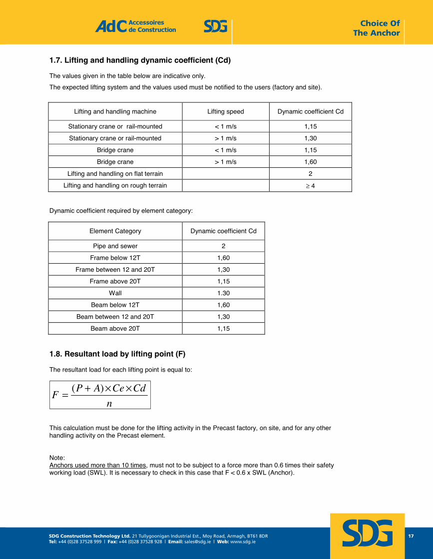
1.7. Lifting and handling dynamic coefficient (Cd)
The values given in the table below are indicative only. The expected lifting system and the values used must be notified to the users (factory and site).
Lifting and handling machine Lifting speed Dynamic coefficient Cd
Stationary crane or rail-mounted < 1 m/s 1,15
Stationary crane or rail-mounted > 1 m/s 1,30
Bridge crane < 1 m/s 1,15
Bridge crane > 1 m/s 1,60
Lifting and handling on flat terrain 2
Lifting and handling on rough terrain ≥ 4
Dynamic coefficient required by element category:
Element Category Dynamic coefficient Cd
Pipe and sewer 2
Frame below 12T 1,60
Frame between 12 and 20T 1,30
Frame above 20T 1,15
Wall 1.30
Beam below 12T 1,60
Beam between 12 and 20T 1,30
Beam above 20T 1,15
1.8. Resultant load by lifting point (F)
The resultant load for each lifting point is equal to:
This calculation must be done for the lifting activity in the Precast factory, on site, and for any other handling activity on the Precast element.
Note: Anchors used more than 10 times, must not to be subject to a force more than 0.6 times their safety working load (SWL). It is necessary to check in this case that F < 0.6 x SWL (Anchor).
nCdCeAPF ××+= )(
SDG Construction Technology Ltd. 21 Tullygoonigan Industrial Est., Moy Road, Armagh, BT61 8DRTel: +44 (0)28 37528 999 | Fax: +44 (0)28 37528 928 | Email: [email protected] | Web: www.sdg.ie
18
noitcurtsnoC ed seriosseccA Tel : +33 1 39 33 18 60 1 rue Jacques Robert Fax : +33 1 39 88 14 42 95500 LE THILLAY moc.sas-cda@cda : liam-E 81 egaPFRANCE moc.sas-cda.www 3102 erbotcO - HAL
1.9. Concrete resistance (fck)
The concrete resistance has to be determined:
• When lifting the element from the mould in the Precast factory • For transportation and installation on site
The minimum permitted resistance of the concrete is 10 MPa.
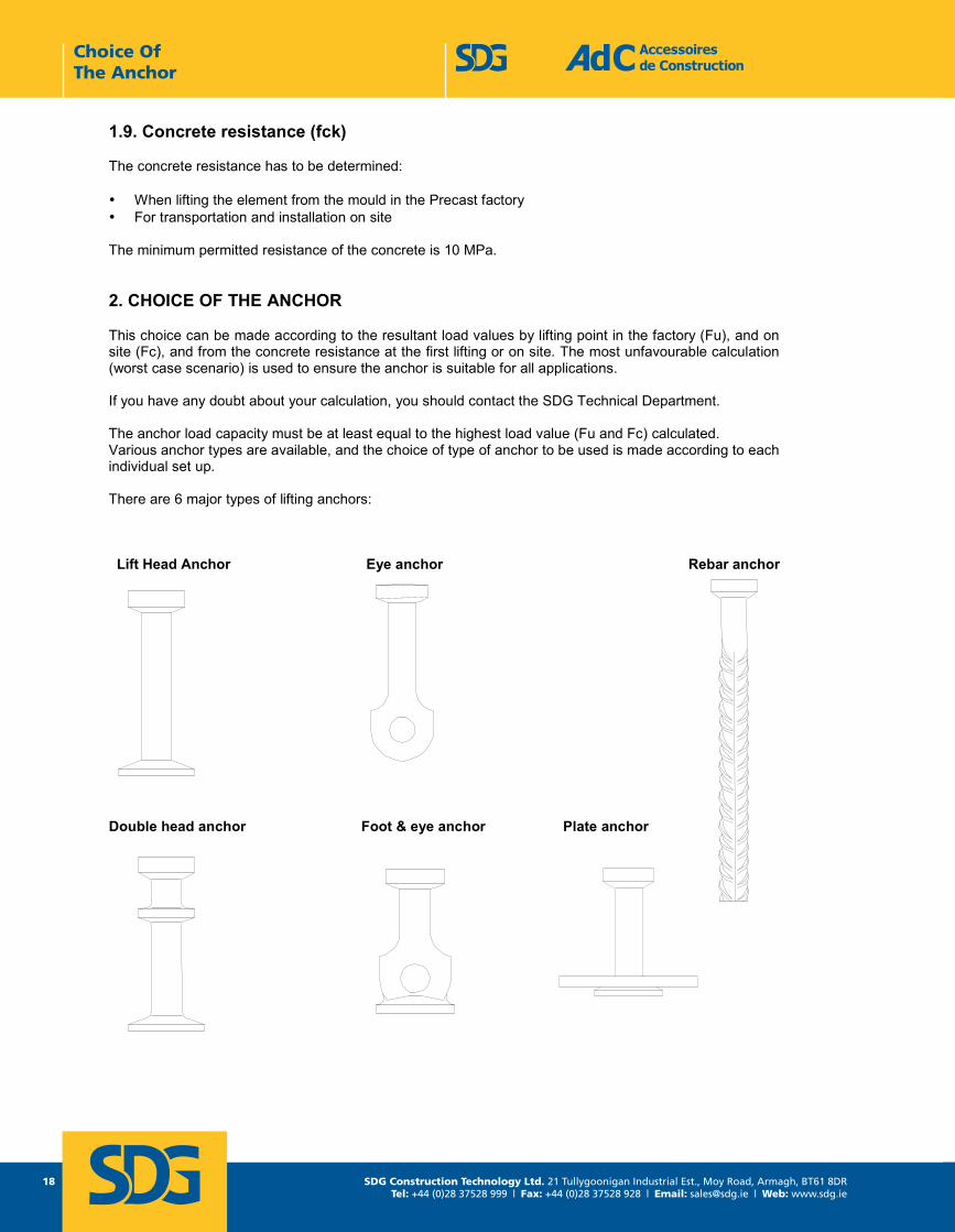
2. CHOICE OF THE ANCHOR
This choice can be made according to the resultant load values by lifting point in the factory (Fu), and on site (Fc), and from the concrete resistance at the first lifting or on site. The most unfavourable calculation (worst case scenario) is used to ensure the anchor is suitable for all applications.
If you have any doubt about your calculation, you should contact the SDG Technical Department. The anchor load capacity must be at least equal to the highest load value (Fu and Fc) calculated. Various anchor types are available, and the choice of type of anchor to be used is made according to each individual set up. There are 6 major types of lifting anchors:
Lift Head Anchor Eye anchor Rebar anchor
Double head anchor Foot & eye anchor Plate anchor
Choice Of The Anchor
SDG Construction Technology Ltd. 21 Tullygoonigan Industrial Est., Moy Road, Armagh, BT61 8DRTel: +44 (0)28 37528 999 | Fax: +44 (0)28 37528 928 | Email: [email protected] | Web: www.sdg.ie
19
Choice Of The Anchor
noitcurtsnoC ed seriosseccA Tel : +33 1 39 33 18 60 1 rue Jacques Robert Fax : +33 1 39 88 14 42 95500 LE THILLAY moc.sas-cda@cda : liam-E 91 egaPFRANCE moc.sas-cda.www 3102 erbotcO - HAL
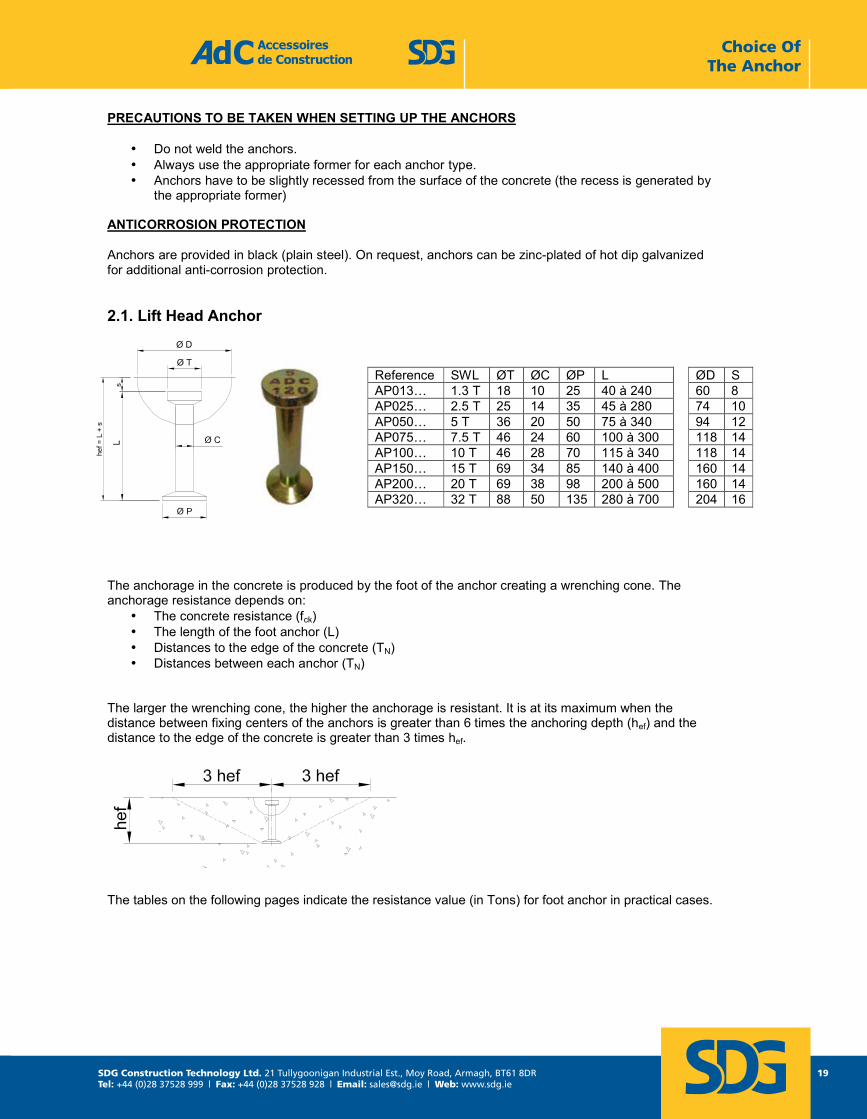
PRECAUTIONS TO BE TAKEN WHEN SETTING UP THE ANCHORS
• Do not weld the anchors. • Always use the appropriate former for each anchor type. • Anchors have to be slightly recessed from the surface of the concrete (the recess is generated by
the appropriate former)
ANTICORROSION PROTECTION
Anchors are provided in black (plain steel). On request, anchors can be zinc-plated of hot dip galvanized for additional anti-corrosion protection.
2.1. Lift Head Anchor
The anchorage in the concrete is produced by the foot of the anchor creating a wrenching cone. The anchorage resistance depends on:
• The concrete resistance (fck) • The length of the foot anchor (L) • Distances to the edge of the concrete (TN) • Distances between each anchor (TN)
The larger the wrenching cone, the higher the anchorage is resistant. It is at its maximum when the distance between fixing centers of the anchors is greater than 6 times the anchoring depth (hef) and the distance to the edge of the concrete is greater than 3 times hef.
The tables on the following pages indicate the resistance value (in Tons) for foot anchor in practical cases.
Reference SWL ØT ØC ØP L ØD S AP013… 1.3 T 18 10 25 40 à 240 60 8 AP025… 2.5 T 25 14 35 45 à 280 74 10AP050… 5 T 36 20 50 75 à 340 94 12AP075… 7.5 T 46 24 60 100 à 300 118 14AP100… 10 T 46 28 70 115 à 340 118 14AP150… 15 T 69 34 85 140 à 400 160 14AP200… 20 T 69 38 98 200 à 500 160 14AP320… 32 T 88 50 135 280 à 700 204 16
SDG Construction Technology Ltd. 21 Tullygoonigan Industrial Est., Moy Road, Armagh, BT61 8DRTel: +44 (0)28 37528 999 | Fax: +44 (0)28 37528 928 | Email: [email protected] | Web: www.sdg.ie
20
noitcurtsnoC ed seriosseccA Tel : +33 1 39 33 18 60 1 rue Jacques Robert Fax : +33 1 39 88 14 42 95500 LE THILLAY moc.sas-cda@cda : liam-E 02 egaPFRANCE moc.sas-cda.www 3102 erbotcO - HAL
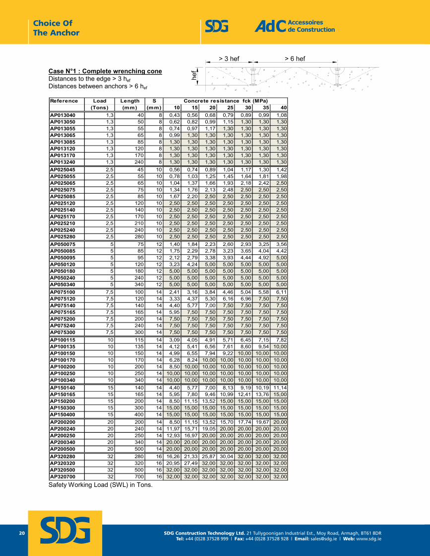
Case N°1 : Complete wrenching cone Distances to the edge > 3 hefDistances between anchors > 6 hef
Reference Load Length S(Tons) (mm) (mm) 10 15 20 25 30 35 40
AP013040 1,3 40 8 0,43 0,56 0,68 0,79 0,89 0,99 1,08AP013050 1,3 50 8 0,62 0,82 0,99 1,15 1,30 1,30 1,30AP013055 1,3 55 8 0,74 0,97 1,17 1,30 1,30 1,30 1,30AP013065 1,3 65 8 0,99 1,30 1,30 1,30 1,30 1,30 1,30AP013085 1,3 85 8 1,30 1,30 1,30 1,30 1,30 1,30 1,30AP013120 1,3 120 8 1,30 1,30 1,30 1,30 1,30 1,30 1,30AP013170 1,3 170 8 1,30 1,30 1,30 1,30 1,30 1,30 1,30AP013240 1,3 240 8 1,30 1,30 1,30 1,30 1,30 1,30 1,30AP025045 2,5 45 10 0,56 0,74 0,89 1,04 1,17 1,30 1,42AP025055 2,5 55 10 0,78 1,03 1,25 1,45 1,64 1,81 1,98AP025065 2,5 65 10 1,04 1,37 1,66 1,93 2,18 2,42 2,50AP025075 2,5 75 10 1,34 1,76 2,13 2,48 2,50 2,50 2,50AP025085 2,5 85 10 1,67 2,20 2,50 2,50 2,50 2,50 2,50AP025120 2,5 120 10 2,50 2,50 2,50 2,50 2,50 2,50 2,50AP025140 2,5 140 10 2,50 2,50 2,50 2,50 2,50 2,50 2,50AP025170 2,5 170 10 2,50 2,50 2,50 2,50 2,50 2,50 2,50AP025210 2,5 210 10 2,50 2,50 2,50 2,50 2,50 2,50 2,50AP025240 2,5 240 10 2,50 2,50 2,50 2,50 2,50 2,50 2,50AP025280 2,5 280 10 2,50 2,50 2,50 2,50 2,50 2,50 2,50AP050075 5 75 12 1,40 1,84 2,23 2,60 2,93 3,25 3,56AP050085 5 85 12 1,75 2,29 2,78 3,23 3,65 4,04 4,42AP050095 5 95 12 2,12 2,79 3,38 3,93 4,44 4,92 5,00AP050120 5 120 12 3,23 4,24 5,00 5,00 5,00 5,00 5,00AP050180 5 180 12 5,00 5,00 5,00 5,00 5,00 5,00 5,00AP050240 5 240 12 5,00 5,00 5,00 5,00 5,00 5,00 5,00AP050340 5 340 12 5,00 5,00 5,00 5,00 5,00 5,00 5,00AP075100 7,5 100 14 2,41 3,16 3,84 4,46 5,04 5,58 6,11AP075120 7,5 120 14 3,33 4,37 5,30 6,16 6,96 7,50 7,50AP075140 7,5 140 14 4,40 5,77 7,00 7,50 7,50 7,50 7,50AP075165 7,5 165 14 5,95 7,50 7,50 7,50 7,50 7,50 7,50AP075200 7,5 200 14 7,50 7,50 7,50 7,50 7,50 7,50 7,50AP075240 7,5 240 14 7,50 7,50 7,50 7,50 7,50 7,50 7,50AP075300 7,5 300 14 7,50 7,50 7,50 7,50 7,50 7,50 7,50AP100115 10 115 14 3,09 4,05 4,91 5,71 6,45 7,15 7,82AP100135 10 135 14 4,12 5,41 6,56 7,61 8,60 9,54 10,00AP100150 10 150 14 4,99 6,55 7,94 9,22 10,00 10,00 10,00AP100170 10 170 14 6,28 8,24 10,00 10,00 10,00 10,00 10,00AP100200 10 200 14 8,50 10,00 10,00 10,00 10,00 10,00 10,00AP100250 10 250 14 10,00 10,00 10,00 10,00 10,00 10,00 10,00AP100340 10 340 14 10,00 10,00 10,00 10,00 10,00 10,00 10,00AP150140 15 140 14 4,40 5,77 7,00 8,13 9,19 10,19 11,14AP150165 15 165 14 5,95 7,80 9,46 10,99 12,41 13,76 15,00AP150200 15 200 14 8,50 11,15 13,52 15,00 15,00 15,00 15,00AP150300 15 300 14 15,00 15,00 15,00 15,00 15,00 15,00 15,00AP150400 15 400 14 15,00 15,00 15,00 15,00 15,00 15,00 15,00AP200200 20 200 14 8,50 11,15 13,52 15,70 17,74 19,67 20,00AP200240 20 240 14 11,97 15,71 19,05 20,00 20,00 20,00 20,00AP200250 20 250 14 12,93 16,97 20,00 20,00 20,00 20,00 20,00AP200340 20 340 14 20,00 20,00 20,00 20,00 20,00 20,00 20,00AP200500 20 500 14 20,00 20,00 20,00 20,00 20,00 20,00 20,00AP320280 32 280 16 16,26 21,33 25,87 30,04 32,00 32,00 32,00AP320320 32 320 16 20,95 27,49 32,00 32,00 32,00 32,00 32,00AP320500 32 500 16 32,00 32,00 32,00 32,00 32,00 32,00 32,00AP320700 32 700 16 32,00 32,00 32,00 32,00 32,00 32,00 32,00
Concrete resistance fck (MPa)
Safety Working Load (SWL) in Tons.
Choice Of The Anchor
SDG Construction Technology Ltd. 21 Tullygoonigan Industrial Est., Moy Road, Armagh, BT61 8DRTel: +44 (0)28 37528 999 | Fax: +44 (0)28 37528 928 | Email: [email protected] | Web: www.sdg.ie
21
Choice Of The Anchor
noitcurtsnoC ed seriosseccA Tel : +33 1 39 33 18 60 1 rue Jacques Robert Fax : +33 1 39 88 14 42 95500 LE THILLAY moc.sas-cda@cda : liam-E 12 egaPFRANCE moc.sas-cda.www 3102 erbotcO - HAL
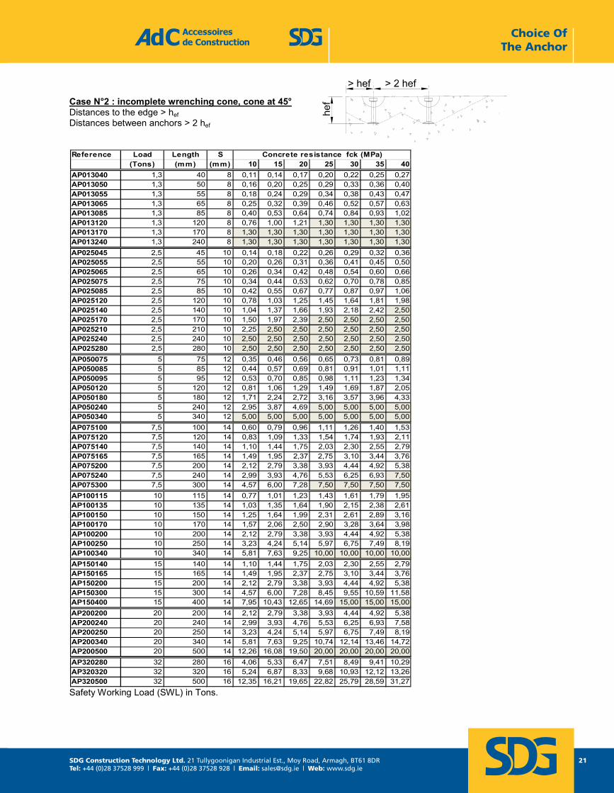
Case N°2 : incomplete wrenching cone, cone at 45° Distances to the edge > hefDistances between anchors > 2 hef
Reference Load Length S(Tons) (mm) (mm) 10 15 20 25 30 35 40
AP013040 1,3 40 8 0,11 0,14 0,17 0,20 0,22 0,25 0,27AP013050 1,3 50 8 0,16 0,20 0,25 0,29 0,33 0,36 0,40AP013055 1,3 55 8 0,18 0,24 0,29 0,34 0,38 0,43 0,47AP013065 1,3 65 8 0,25 0,32 0,39 0,46 0,52 0,57 0,63AP013085 1,3 85 8 0,40 0,53 0,64 0,74 0,84 0,93 1,02AP013120 1,3 120 8 0,76 1,00 1,21 1,30 1,30 1,30 1,30AP013170 1,3 170 8 1,30 1,30 1,30 1,30 1,30 1,30 1,30AP013240 1,3 240 8 1,30 1,30 1,30 1,30 1,30 1,30 1,30AP025045 2,5 45 10 0,14 0,18 0,22 0,26 0,29 0,32 0,36AP025055 2,5 55 10 0,20 0,26 0,31 0,36 0,41 0,45 0,50AP025065 2,5 65 10 0,26 0,34 0,42 0,48 0,54 0,60 0,66AP025075 2,5 75 10 0,34 0,44 0,53 0,62 0,70 0,78 0,85AP025085 2,5 85 10 0,42 0,55 0,67 0,77 0,87 0,97 1,06AP025120 2,5 120 10 0,78 1,03 1,25 1,45 1,64 1,81 1,98AP025140 2,5 140 10 1,04 1,37 1,66 1,93 2,18 2,42 2,50AP025170 2,5 170 10 1,50 1,97 2,39 2,50 2,50 2,50 2,50AP025210 2,5 210 10 2,25 2,50 2,50 2,50 2,50 2,50 2,50AP025240 2,5 240 10 2,50 2,50 2,50 2,50 2,50 2,50 2,50AP025280 2,5 280 10 2,50 2,50 2,50 2,50 2,50 2,50 2,50AP050075 5 75 12 0,35 0,46 0,56 0,65 0,73 0,81 0,89AP050085 5 85 12 0,44 0,57 0,69 0,81 0,91 1,01 1,11AP050095 5 95 12 0,53 0,70 0,85 0,98 1,11 1,23 1,34AP050120 5 120 12 0,81 1,06 1,29 1,49 1,69 1,87 2,05AP050180 5 180 12 1,71 2,24 2,72 3,16 3,57 3,96 4,33AP050240 5 240 12 2,95 3,87 4,69 5,00 5,00 5,00 5,00AP050340 5 340 12 5,00 5,00 5,00 5,00 5,00 5,00 5,00AP075100 7,5 100 14 0,60 0,79 0,96 1,11 1,26 1,40 1,53AP075120 7,5 120 14 0,83 1,09 1,33 1,54 1,74 1,93 2,11AP075140 7,5 140 14 1,10 1,44 1,75 2,03 2,30 2,55 2,79AP075165 7,5 165 14 1,49 1,95 2,37 2,75 3,10 3,44 3,76AP075200 7,5 200 14 2,12 2,79 3,38 3,93 4,44 4,92 5,38AP075240 7,5 240 14 2,99 3,93 4,76 5,53 6,25 6,93 7,50AP075300 7,5 300 14 4,57 6,00 7,28 7,50 7,50 7,50 7,50AP100115 10 115 14 0,77 1,01 1,23 1,43 1,61 1,79 1,95AP100135 10 135 14 1,03 1,35 1,64 1,90 2,15 2,38 2,61AP100150 10 150 14 1,25 1,64 1,99 2,31 2,61 2,89 3,16AP100170 10 170 14 1,57 2,06 2,50 2,90 3,28 3,64 3,98AP100200 10 200 14 2,12 2,79 3,38 3,93 4,44 4,92 5,38AP100250 10 250 14 3,23 4,24 5,14 5,97 6,75 7,49 8,19AP100340 10 340 14 5,81 7,63 9,25 10,00 10,00 10,00 10,00AP150140 15 140 14 1,10 1,44 1,75 2,03 2,30 2,55 2,79AP150165 15 165 14 1,49 1,95 2,37 2,75 3,10 3,44 3,76AP150200 15 200 14 2,12 2,79 3,38 3,93 4,44 4,92 5,38AP150300 15 300 14 4,57 6,00 7,28 8,45 9,55 10,59 11,58AP150400 15 400 14 7,95 10,43 12,65 14,69 15,00 15,00 15,00AP200200 20 200 14 2,12 2,79 3,38 3,93 4,44 4,92 5,38AP200240 20 240 14 2,99 3,93 4,76 5,53 6,25 6,93 7,58AP200250 20 250 14 3,23 4,24 5,14 5,97 6,75 7,49 8,19AP200340 20 340 14 5,81 7,63 9,25 10,74 12,14 13,46 14,72AP200500 20 500 14 12,26 16,08 19,50 20,00 20,00 20,00 20,00AP320280 32 280 16 4,06 5,33 6,47 7,51 8,49 9,41 10,29AP320320 32 320 16 5,24 6,87 8,33 9,68 10,93 12,12 13,26AP320500 32 500 16 12,35 16,21 19,65 22,82 25,79 28,59 31,27
Concrete resistance fck (MPa)
Safety Working Load (SWL) in Tons.
SDG Construction Technology Ltd. 21 Tullygoonigan Industrial Est., Moy Road, Armagh, BT61 8DRTel: +44 (0)28 37528 999 | Fax: +44 (0)28 37528 928 | Email: [email protected] | Web: www.sdg.ie
22
Accessoires de Construction Tel : +33 1 39 33 18 60 1 rue Jacques Robert Fax : +33 1 39 88 14 42 95500 LE THILLAY Page 22 E-mail : [email protected] FRANCE LAH - Octobre 2013 www.adc-sas.com
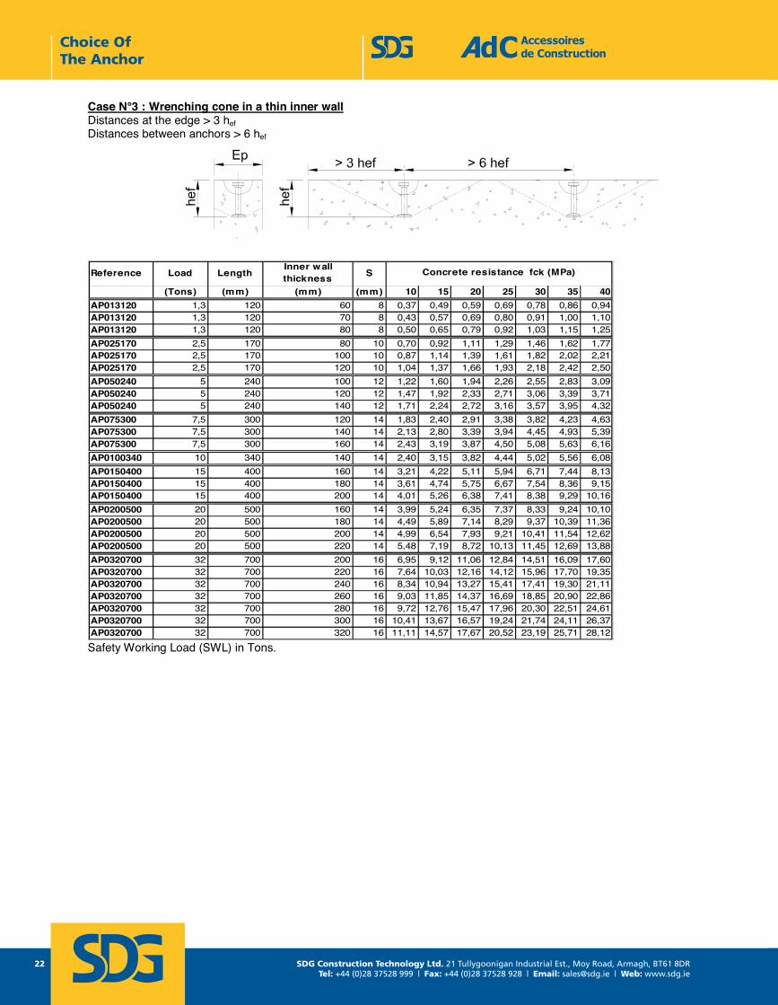
Case N°3 : Wrenching cone in a thin inner wall Distances at the edge > 3 hefDistances between anchors > 6 hef
Reference Load LengthInner wall thickness S
(Tons) (mm) (mm) (mm) 10 15 20 25 30 35 40AP013120 1,3 120 60 8 0,37 0,49 0,59 0,69 0,78 0,86 0,94AP013120 1,3 120 70 8 0,43 0,57 0,69 0,80 0,91 1,00 1,10AP013120 1,3 120 80 8 0,50 0,65 0,79 0,92 1,03 1,15 1,25AP025170 2,5 170 80 10 0,70 0,92 1,11 1,29 1,46 1,62 1,77AP025170 2,5 170 100 10 0,87 1,14 1,39 1,61 1,82 2,02 2,21AP025170 2,5 170 120 10 1,04 1,37 1,66 1,93 2,18 2,42 2,50AP050240 5 240 100 12 1,22 1,60 1,94 2,26 2,55 2,83 3,09AP050240 5 240 120 12 1,47 1,92 2,33 2,71 3,06 3,39 3,71AP050240 5 240 140 12 1,71 2,24 2,72 3,16 3,57 3,95 4,32AP075300 7,5 300 120 14 1,83 2,40 2,91 3,38 3,82 4,23 4,63AP075300 7,5 300 140 14 2,13 2,80 3,39 3,94 4,45 4,93 5,39AP075300 7,5 300 160 14 2,43 3,19 3,87 4,50 5,08 5,63 6,16AP0100340 10 340 140 14 2,40 3,15 3,82 4,44 5,02 5,56 6,08AP0150400 15 400 160 14 3,21 4,22 5,11 5,94 6,71 7,44 8,13AP0150400 15 400 180 14 3,61 4,74 5,75 6,67 7,54 8,36 9,15AP0150400 15 400 200 14 4,01 5,26 6,38 7,41 8,38 9,29 10,16AP0200500 20 500 160 14 3,99 5,24 6,35 7,37 8,33 9,24 10,10AP0200500 20 500 180 14 4,49 5,89 7,14 8,29 9,37 10,39 11,36AP0200500 20 500 200 14 4,99 6,54 7,93 9,21 10,41 11,54 12,62AP0200500 20 500 220 14 5,48 7,19 8,72 10,13 11,45 12,69 13,88AP0320700 32 700 200 16 6,95 9,12 11,06 12,84 14,51 16,09 17,60AP0320700 32 700 220 16 7,64 10,03 12,16 14,12 15,96 17,70 19,35AP0320700 32 700 240 16 8,34 10,94 13,27 15,41 17,41 19,30 21,11AP0320700 32 700 260 16 9,03 11,85 14,37 16,69 18,85 20,90 22,86AP0320700 32 700 280 16 9,72 12,76 15,47 17,96 20,30 22,51 24,61AP0320700 32 700 300 16 10,41 13,67 16,57 19,24 21,74 24,11 26,37AP0320700 32 700 320 16 11,11 14,57 17,67 20,52 23,19 25,71 28,12
Concrete resistance fck (MPa)
Safety Working Load (SWL) in Tons.
Choice Of The Anchor
SDG Construction Technology Ltd. 21 Tullygoonigan Industrial Est., Moy Road, Armagh, BT61 8DRTel: +44 (0)28 37528 999 | Fax: +44 (0)28 37528 928 | Email: [email protected] | Web: www.sdg.ie
23
Accessoires de Construction Tel : +33 1 39 33 18 60 1 rue Jacques Robert Fax : +33 1 39 88 14 42 95500 LE THILLAY Page 23 E-mail : [email protected] FRANCE LAH - Octobre 2013 www.adc-sas.com
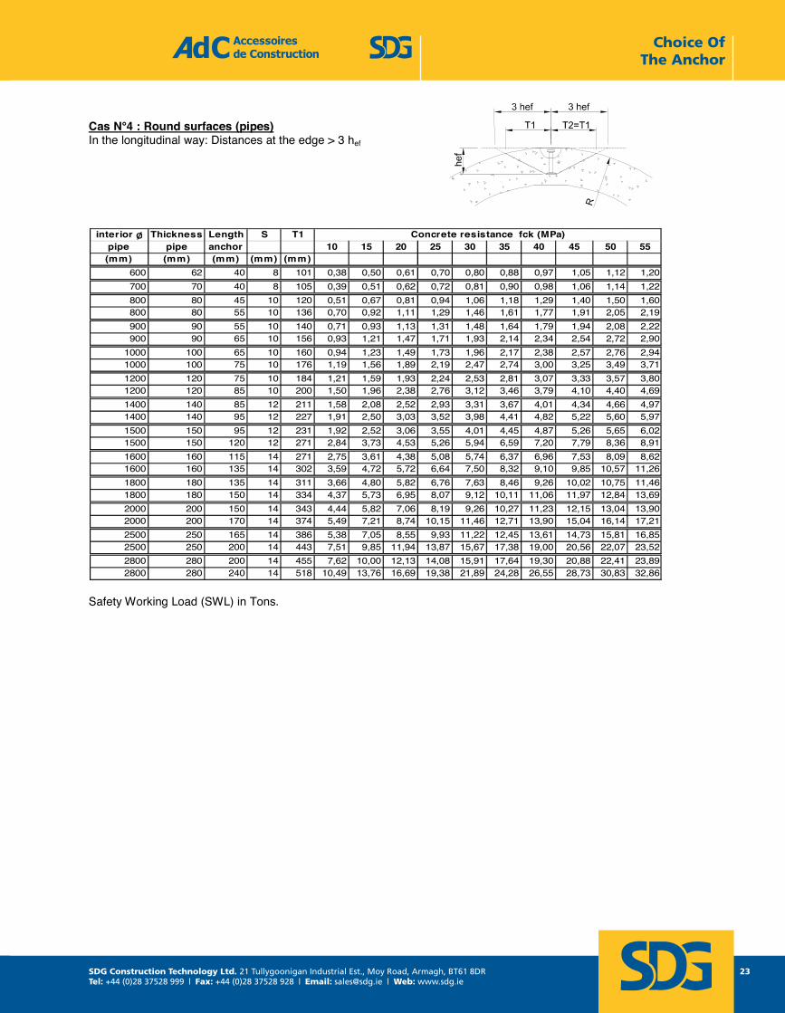
Cas N°4 : Round surfaces (pipes)In the longitudinal way: Distances at the edge > 3 hef
interior Ø Thickness Length S T1pipe pipe anchor 10 15 20 25 30 35 40 45 50 55(mm) (mm) (mm) (mm) (mm)
600 62 40 8 101 0,38 0,50 0,61 0,70 0,80 0,88 0,97 1,05 1,12 1,20700 70 40 8 105 0,39 0,51 0,62 0,72 0,81 0,90 0,98 1,06 1,14 1,22800 80 45 10 120 0,51 0,67 0,81 0,94 1,06 1,18 1,29 1,40 1,50 1,60800 80 55 10 136 0,70 0,92 1,11 1,29 1,46 1,61 1,77 1,91 2,05 2,19900 90 55 10 140 0,71 0,93 1,13 1,31 1,48 1,64 1,79 1,94 2,08 2,22900 90 65 10 156 0,93 1,21 1,47 1,71 1,93 2,14 2,34 2,54 2,72 2,90
1000 100 65 10 160 0,94 1,23 1,49 1,73 1,96 2,17 2,38 2,57 2,76 2,941000 100 75 10 176 1,19 1,56 1,89 2,19 2,47 2,74 3,00 3,25 3,49 3,711200 120 75 10 184 1,21 1,59 1,93 2,24 2,53 2,81 3,07 3,33 3,57 3,801200 120 85 10 200 1,50 1,96 2,38 2,76 3,12 3,46 3,79 4,10 4,40 4,691400 140 85 12 211 1,58 2,08 2,52 2,93 3,31 3,67 4,01 4,34 4,66 4,971400 140 95 12 227 1,91 2,50 3,03 3,52 3,98 4,41 4,82 5,22 5,60 5,971500 150 95 12 231 1,92 2,52 3,06 3,55 4,01 4,45 4,87 5,26 5,65 6,021500 150 120 12 271 2,84 3,73 4,53 5,26 5,94 6,59 7,20 7,79 8,36 8,911600 160 115 14 271 2,75 3,61 4,38 5,08 5,74 6,37 6,96 7,53 8,09 8,621600 160 135 14 302 3,59 4,72 5,72 6,64 7,50 8,32 9,10 9,85 10,57 11,261800 180 135 14 311 3,66 4,80 5,82 6,76 7,63 8,46 9,26 10,02 10,75 11,461800 180 150 14 334 4,37 5,73 6,95 8,07 9,12 10,11 11,06 11,97 12,84 13,692000 200 150 14 343 4,44 5,82 7,06 8,19 9,26 10,27 11,23 12,15 13,04 13,902000 200 170 14 374 5,49 7,21 8,74 10,15 11,46 12,71 13,90 15,04 16,14 17,212500 250 165 14 386 5,38 7,05 8,55 9,93 11,22 12,45 13,61 14,73 15,81 16,852500 250 200 14 443 7,51 9,85 11,94 13,87 15,67 17,38 19,00 20,56 22,07 23,522800 280 200 14 455 7,62 10,00 12,13 14,08 15,91 17,64 19,30 20,88 22,41 23,892800 280 240 14 518 10,49 13,76 16,69 19,38 21,89 24,28 26,55 28,73 30,83 32,86
Concrete resistance fck (MPa)
Safety Working Load (SWL) in Tons.
Choice Of The Anchor
SDG Construction Technology Ltd. 21 Tullygoonigan Industrial Est., Moy Road, Armagh, BT61 8DRTel: +44 (0)28 37528 999 | Fax: +44 (0)28 37528 928 | Email: [email protected] | Web: www.sdg.ie
24
Accessoires de Construction Tel : +33 1 39 33 18 60 1 rue Jacques Robert Fax : +33 1 39 88 14 42 95500 LE THILLAY Page 24 E-mail : [email protected] FRANCE LAH - Octobre 2013 www.adc-sas.com
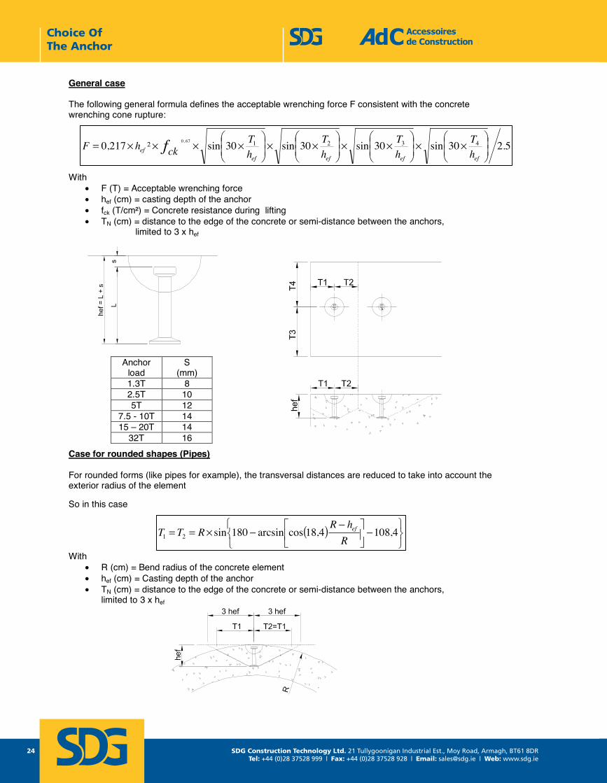
General case
The following general formula defines the acceptable wrenching force F consistent with the concrete wrenching cone rupture:
With • F (T) = Acceptable wrenching force • hef (cm) = casting depth of the anchor • fck (T/cm²) = Concrete resistance during lifting • TN (cm) = distance to the edge of the concrete or semi-distance between the anchors,
limited to 3 x hef
Case for rounded shapes (Pipes)
For rounded forms (like pipes for example), the transversal distances are reduced to take into account the exterior radius of the element
So in this case
With • R (cm) = Bend radius of the concrete element • hef (cm) = Casting depth of the anchor • TN (cm) = distance to the edge of the concrete or semi-distance between the anchors,
limited to 3 x hef
Anchor load
S (mm)
1.3T 8 2.5T 10 5T 12
7.5 - 10T 14 15 – 20T 14
32T 16
5.230sin30sin30sin30sin²217,0 432167,0
××
××
××
××××=
efefefefef h
ThT
hT
hT
ckhF f
( )
−
−−×== 4,1084,18cosarcsin180sin21 R
hRRTT ef
Choice Of The Anchor
SDG Construction Technology Ltd. 21 Tullygoonigan Industrial Est., Moy Road, Armagh, BT61 8DRTel: +44 (0)28 37528 999 | Fax: +44 (0)28 37528 928 | Email: [email protected] | Web: www.sdg.ie
25
noitcurtsnoC ed seriosseccA Tel : +33 1 39 33 18 60 1 rue Jacques Robert Fax : +33 1 39 88 14 42 95500 LE THILLAY moc.sas-cda@cda : liam-E 52 egaPFRANCE moc.sas-cda.www 3102 erbotcO - HAL
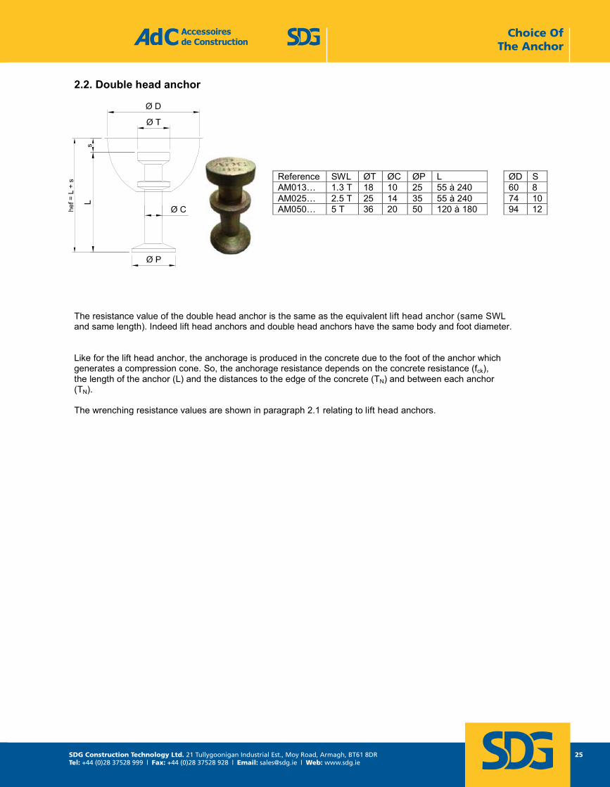
2.2. Double head anchor
The resistance value of the double head anchor is the same as the equivalent lift head anchor (same SWL and same length). Indeed lift head anchors and double head anchors have the same body and foot diameter.
Like for the lift head anchor, the anchorage is produced in the concrete due to the foot of the anchor whichgenerates a compression cone. So, the anchorage resistance depends on the concrete resistance (fck), the length of the anchor (L) and the distances to the edge of the concrete (TN) and between each anchor (TN).
The wrenching resistance values are shown in paragraph 2.1 relating to lift head anchors.
Reference SWL ØT ØC ØP L ØD S AM013… 1.3 T 18 10 25 55 à 240 60 8 AM025… 2.5 T 25 14 35 55 à 240 74 10AM050… 5 T 36 20 50 120 à 180 94 12
Choice Of The Anchor
SDG Construction Technology Ltd. 21 Tullygoonigan Industrial Est., Moy Road, Armagh, BT61 8DRTel: +44 (0)28 37528 999 | Fax: +44 (0)28 37528 928 | Email: [email protected] | Web: www.sdg.ie
26
noitcurtsnoC ed seriosseccA Tel : +33 1 39 33 18 60 1 rue Jacques Robert Fax : +33 1 39 88 14 42 95500 LE THILLAY moc.sas-cda@cda : liam-E 62 egaPFRANCE moc.sas-cda.www 3102 erbotcO - HAL
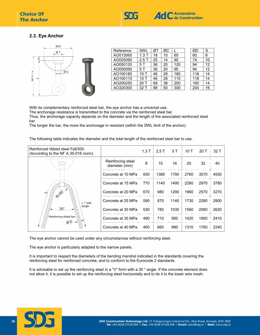
2.3. Eye Anchor
With its complementary reinforced steel bar, the eye anchor has a universal use. The anchorage resistance is transmitted to the concrete via the reinforced steel bar. Thus, the anchorage capacity depends on the diameter and the length of the associated reinforced steelbar. The longer the bar, the more the anchorage in resistant (within the SWL limit of the anchor).
The following table indicates the diameter and the total length of the reinforced steel bar to use.
Reinforced ribbed steel FeE500, (According to the NF A 35-016 norm). 1,3 T 2,5 T 5 T 10 T 20 T 32 T
Reinforcing steel diameter (mm) 8 10 16 20 32 40
Concrete at 10 MPa 930 1380 1790 2760 3570 4550
Concrete at 15 MPa 770 1140 1490 2280 2970 3780
Concrete at 20 MPa 670 980 1290 1960 2570 3270
Concrete at 25 MPa 590 870 1140 1730 2280 2900
Concrete at 30 MPa 530 780 1030 1560 2060 2620
Concrete at 35 MPa 490 710 950 1420 1900 2410
Concrete at 40 MPa 460 660 880 1310 1760 2240
The eye anchor cannot be used under any circumstances without reinforcing steel.
The eye anchor is particularly adapted to the narrow panels.
It is important to respect the diameters of the bending mandrel indicated in the standards covering the reinforcing steel for reinforced concrete, and to conform to the Eurocode 2 standards.
It is advisable to set up the reinforcing steel in a "V" form with a 30 ° angle. If the concrete element does not allow it, it is possible to set up the reinforcing steel horizontally and to tie it to the lower wire mesh.
Reference SWL ØT ØC L ØD S AO013065 1.3 T 18 10 65 60 8 AO025090 2.5 T 25 14 90 74 10 AO050120 5 T 36 20 120 94 12 AO050090 5 T 36 20 90 94 12 AO100180 10 T 46 28 180 118 14 AO100115 10 T 46 28 115 118 14 AO200250 20 T 69 38 250 160 14 AO320300 32 T 88 50 300 204 16
Choice Of The Anchor
SDG Construction Technology Ltd. 21 Tullygoonigan Industrial Est., Moy Road, Armagh, BT61 8DRTel: +44 (0)28 37528 999 | Fax: +44 (0)28 37528 928 | Email: [email protected] | Web: www.sdg.ie
27
noitcurtsnoC ed seriosseccA Tel : +33 1 39 33 18 60 1 rue Jacques Robert Fax : +33 1 39 88 14 42 95500 LE THILLAY moc.sas-cda@cda : liam-E 72 egaPFRANCE moc.sas-cda.www 3102 erbotcO - HAL
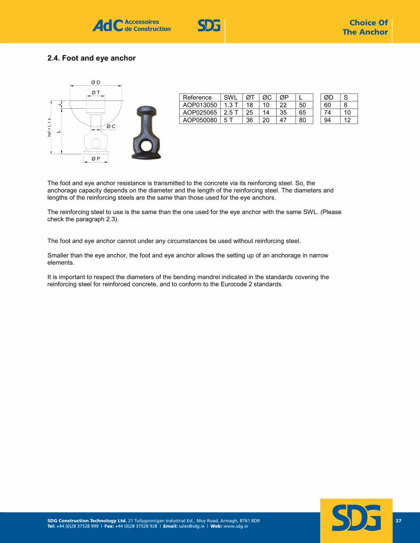
2.4. Foot and eye anchor
The foot and eye anchor resistance is transmitted to the concrete via its reinforcing steel. So, the anchorage capacity depends on the diameter and the length of the reinforcing steel. The diameters and lengths of the reinforcing steels are the same than those used for the eye anchors.
The reinforcing steel to use is the same than the one used for the eye anchor with the same SWL. (Please check the paragraph 2.3).
The foot and eye anchor cannot under any circumstances be used without reinforcing steel.
Smaller than the eye anchor, the foot and eye anchor allows the setting up of an anchorage in narrow elements.
It is important to respect the diameters of the bending mandrel indicated in the standards covering the reinforcing steel for reinforced concrete, and to conform to the Eurocode 2 standards.
Reference SWL ØT ØC ØP L ØD S AOP013050 1.3 T 18 10 22 50 60 8 AOP025065 2.5 T 25 14 35 65 74 10 AOP050080 5 T 36 20 47 80 94 12
Choice Of The Anchor
SDG Construction Technology Ltd. 21 Tullygoonigan Industrial Est., Moy Road, Armagh, BT61 8DRTel: +44 (0)28 37528 999 | Fax: +44 (0)28 37528 928 | Email: [email protected] | Web: www.sdg.ie
28
noitcurtsnoC ed seriosseccA Tel : +33 1 39 33 18 60 1 rue Jacques Robert Fax : +33 1 39 88 14 42 95500 LE THILLAY moc.sas-cda@cda : liam-E 82 egaPFRANCE moc.sas-cda.www 3102 erbotcO - HAL
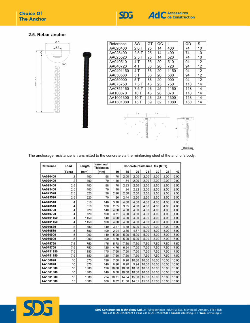
2.5. Rebar anchor
The anchorage resistance is transmitted to the concrete via the reinforcing steel of the anchor’s body.
Reference Load Length Inner wall Thickness Concrete resistance fck (MPa)
(Tons) (mm) (mm) 10 15 20 25 30 35 40AA020400 2 400 98 1.70 2.00 2.00 2.00 2.00 2.00 2.00AA020400 2 400 70 1.40 1.84 2.00 2.00 2.00 2.00 2.00AA025400 2.5 400 98 1.70 2.23 2.50 2.50 2.50 2.50 2.50AA025400 2.5 400 70 1.40 1.84 2.22 2.50 2.50 2.50 2.50AA025520 2.5 520 98 2.26 2.50 2.50 2.50 2.50 2.50 2.50AA025520 2.5 520 70 1.86 2.44 2.50 2.50 2.50 2.50 2.50AA040510 4 510 140 3.10 4.00 4.00 4.00 4.00 4.00 4.00AA040510 4 510 100 2.55 3.35 4.00 4.00 4.00 4.00 4.00AA040720 4 720 140 4.00 4.00 4.00 4.00 4.00 4.00 4.00AA040720 4 720 100 3.71 4.00 4.00 4.00 4.00 4.00 4.00AA0401150 4 1150 140 4.00 4.00 4.00 4.00 4.00 4.00 4.00AA0401150 4 1150 100 4.00 4.00 4.00 4.00 4.00 4.00 4.00AA050580 5 580 140 3.57 4.68 5.00 5.00 5.00 5.00 5.00AA050580 5 580 100 2.94 3.85 4.67 5.00 5.00 5.00 5.00AA050900 5 900 140 5.00 5.00 5.00 5.00 5.00 5.00 5.00AA050900 5 900 100 4.70 5.00 5.00 5.00 5.00 5.00 5.00AA075750 7.5 750 175 5.78 7.50 7.50 7.50 7.50 7.50 7.50AA075750 7.5 750 125 4.76 6.24 7.50 7.50 7.50 7.50 7.50AA0751150 7.5 1150 175 7.50 7.50 7.50 7.50 7.50 7.50 7.50AA0751150 7.5 1150 125 7.50 7.50 7.50 7.50 7.50 7.50 7.50AA100870 10 870 196 7.60 9.96 10.00 10.00 10.00 10.00 10.00AA100870 10 870 140 6.26 8.20 9.94 10.00 10.00 10.00 10.00AA1001300 10 1300 196 10.00 10.00 10.00 10.00 10.00 10.00 10.00AA1001300 10 1300 140 9.58 10.00 10.00 10.00 10.00 10.00 10.00AA1501080 15 1080 224 10.71 14.04 15.00 15.00 15.00 15.00 15.00AA1501080 15 1080 160 8.82 11.56 14.01 15.00 15.00 15.00 15.00
Reference SWL ØT ØC L ØD S AA020400 2.0 T 25 14 400 74 10 AA025400 2.5 T 25 14 400 74 10 AA025520 2.5 T 25 14 520 74 10 AA040510 4 T 36 20 510 94 12 AA040720 4 T 36 20 720 94 12 AA0401150 4 T 36 20 1150 94 12 AA050580 5 T 36 20 580 94 12 AA050900 5 T 36 20 900 94 12 AA075750 7.5 T 46 25 750 118 14 AA0751150 7.5 T 46 25 1150 118 14 AA100870 10 T 46 28 870 118 14 AA1001300 10 T 46 28 1300 118 14 AA1501080 15 T 69 32 1080 160 14
Choice Of The Anchor
SDG Construction Technology Ltd. 21 Tullygoonigan Industrial Est., Moy Road, Armagh, BT61 8DRTel: +44 (0)28 37528 999 | Fax: +44 (0)28 37528 928 | Email: [email protected] | Web: www.sdg.ie
29
Accessoires de Construction Tel : +33 1 39 33 18 60 1 rue Jacques Robert Fax : +33 1 39 88 14 42 95500 LE THILLAY Page 29 E-mail : [email protected] FRANCE LAH - Octobre 2013 www.adc-sas.com
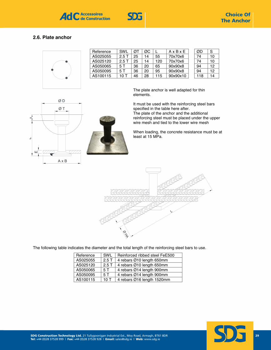
2.6. Plate anchor
The plate anchor is well adapted for thin elements.
It must be used with the reinforcing steel bars specified in the table here after. The plate of the anchor and the additional reinforcing steel must be placed under the upper wire mesh and tied to the lower wire mesh
When loading, the concrete resistance must be at least at 15 MPa.
The following table indicates the diameter and the total length of the reinforcing steel bars to use.
Reference SWL ØT ØC L A x B x E ØD SAS025055 2.5 T 25 14 55 70x70x6 74 10 AS025120 2.5 T 25 14 120 70x70x6 74 10 AS050065 5 T 36 20 65 90x90x8 94 12AS050095 5 T 36 20 95 90x90x8 94 12 AS100115 10 T 46 28 115 90x90x10 118 14
Reference SWL Reinforced ribbed steel FeE500 AS025055 2.5 T 4 rebars Ø10 length 650mm AS025120 2.5 T 4 rebars Ø10 length 650mm AS050065 5 T 4 rebars Ø14 length 900mm AS050095 5 T 4 rebars Ø14 length 900mm AS100115 10 T 4 rebars Ø16 length 1520mm
Choice Of The Anchor
SDG Construction Technology Ltd. 21 Tullygoonigan Industrial Est., Moy Road, Armagh, BT61 8DRTel: +44 (0)28 37528 999 | Fax: +44 (0)28 37528 928 | Email: [email protected] | Web: www.sdg.ie
30
noitcurtsnoC ed seriosseccA Tel : +33 1 39 33 18 60 1 rue Jacques Robert Fax : +33 1 39 88 14 42 95500 LE THILLAY moc.sas-cda@cda : liam-E 03 egaPFRANCE moc.sas-cda.www 3102 erbotcO - HAL
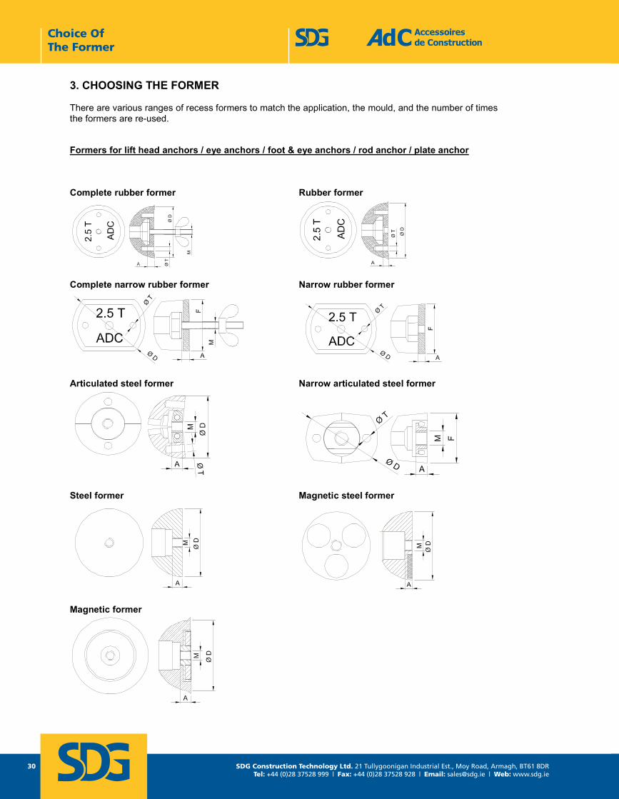
3. CHOOSING THE FORMER
There are various ranges of recess formers to match the application, the mould, and the number of times the formers are re-used.
Formers for lift head anchors / eye anchors / foot & eye anchors / rod anchor / plate anchor
Complete rubber former Rubber former
Complete narrow rubber former Narrow rubber former
Articulated steel former Narrow articulated steel former
Steel former Magnetic steel former
Magnetic former
Choice Of The Former
SDG Construction Technology Ltd. 21 Tullygoonigan Industrial Est., Moy Road, Armagh, BT61 8DRTel: +44 (0)28 37528 999 | Fax: +44 (0)28 37528 928 | Email: [email protected] | Web: www.sdg.ie
31
Accessoires de Construction Tel : +33 1 39 33 18 60 1 rue Jacques Robert Fax : +33 1 39 88 14 42 95500 LE THILLAY Page 31 E-mail : [email protected] FRANCE LAH - Octobre 2013 www.adc-sas.com
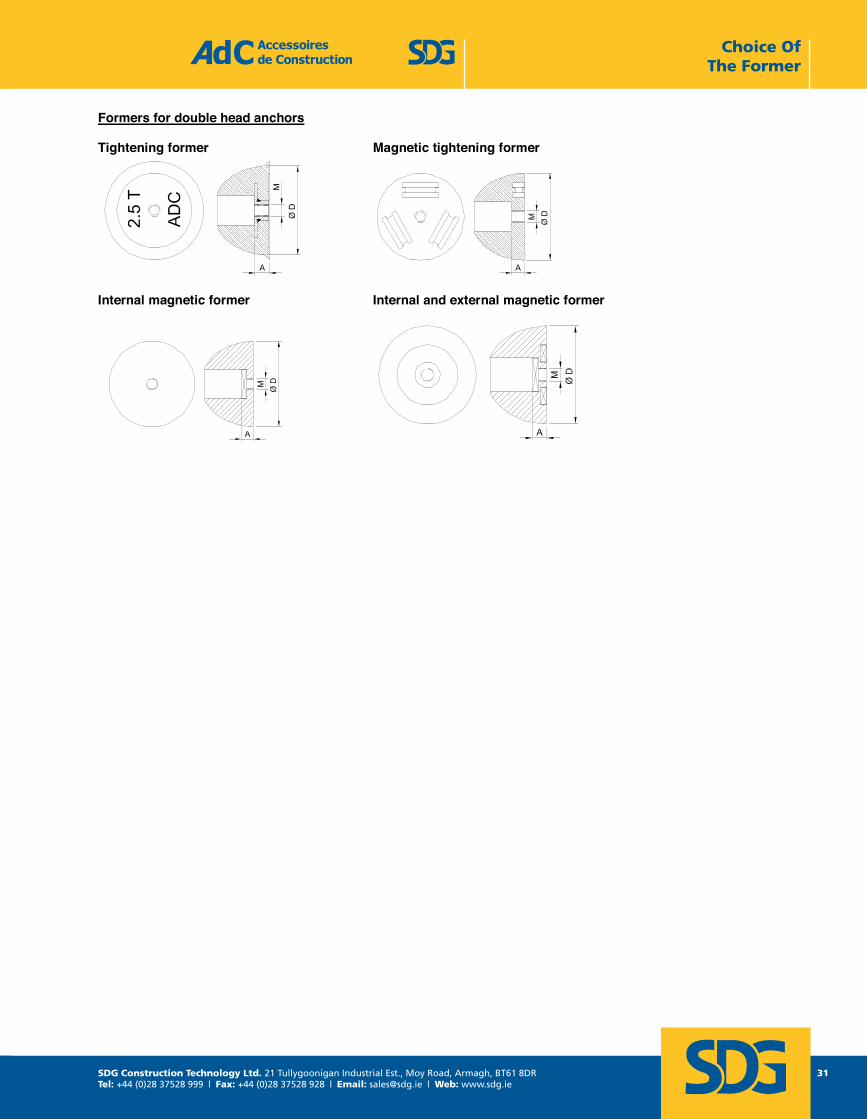
Formers for double head anchors
Tightening former Magnetic tightening former
Internal magnetic former Internal and external magnetic former
Choice Of The Former
SDG Construction Technology Ltd. 21 Tullygoonigan Industrial Est., Moy Road, Armagh, BT61 8DRTel: +44 (0)28 37528 999 | Fax: +44 (0)28 37528 928 | Email: [email protected] | Web: www.sdg.ie
32
noitcurtsnoC ed seriosseccA Tel : +33 1 39 33 18 60 1 rue Jacques Robert Fax : +33 1 39 88 14 42 95500 LE THILLAY moc.sas-cda@cda : liam-E 23 egaPFRANCE moc.sas-cda.www 3102 erbotcO - HAL
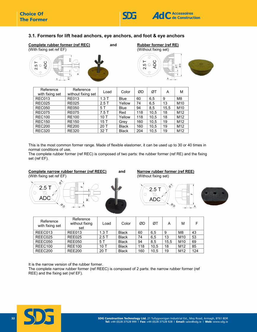
3.1. Formers for lift head anchors, eye anchors, and foot & eye anchors
Complete rubber former (ref REC) and Rubber former (ref RE) (With fixing set ref EF) (Without fixing set)
This is the most common former range. Made of flexible elastomer, it can be used up to 30 or 40 times in normal conditions of use. The complete rubber former (ref REC) is composed of two parts: the rubber former (ref RE) and the fixing set (ref EF).
Complete narrow rubber former (ref REEC) and Narrow rubber former (ref REE) (With fixing set ref EF) (Without fixing set)
It is the narrow version of the rubber former. The complete narrow rubber former (ref REEC) is composed of 2 parts: the narrow rubber former (ref REE) and the fixing set (ref EF).
Reference with fixing set
Reference without fixing set Load Color ØD ØT A M
REC013 RE013 1.3 T Blue 60 6,5 9 M8 REC025 RE025 2.5 T Yellow 74 6,5 13 M10 REC050 RE050 5 T Blue 94 8,5 15,5 M10 REC075 RE075 7.5 T Red 118 10,5 18 M12 REC100 RE100 10 T Yellow 118 10,5 18 M12 REC150 RE150 15 T Grey 160 10,5 19 M12 REC200 RE200 20 T Black 160 10,5 19 M12 REC320 RE320 32 T Black 204 10,5 19 M12
Reference with fixing set
Reference without fixing
set Load Color ØD ØT A M F
REEC013 REE013 1.3 T Black 60 6,5 9 M8 43 REEC025 REE025 2.5 T Black 74 6,5 13 M10 53 REEC050 REE050 5 T Black 94 8,5 15,5 M10 69 REEC100 REE100 10 T Black 118 10,5 18 M12 85 REEC200 REE200 20 T Black 160 10,5 19 M12 124
Choice Of The Former
SDG Construction Technology Ltd. 21 Tullygoonigan Industrial Est., Moy Road, Armagh, BT61 8DRTel: +44 (0)28 37528 999 | Fax: +44 (0)28 37528 928 | Email: [email protected] | Web: www.sdg.ie
33
Accessoires de Construction Tel : +33 1 39 33 18 60 1 rue Jacques Robert Fax : +33 1 39 88 14 42 95500 LE THILLAY Page 33 E-mail : [email protected] FRANCE LAH - Octobre 2013 www.adc-sas.com
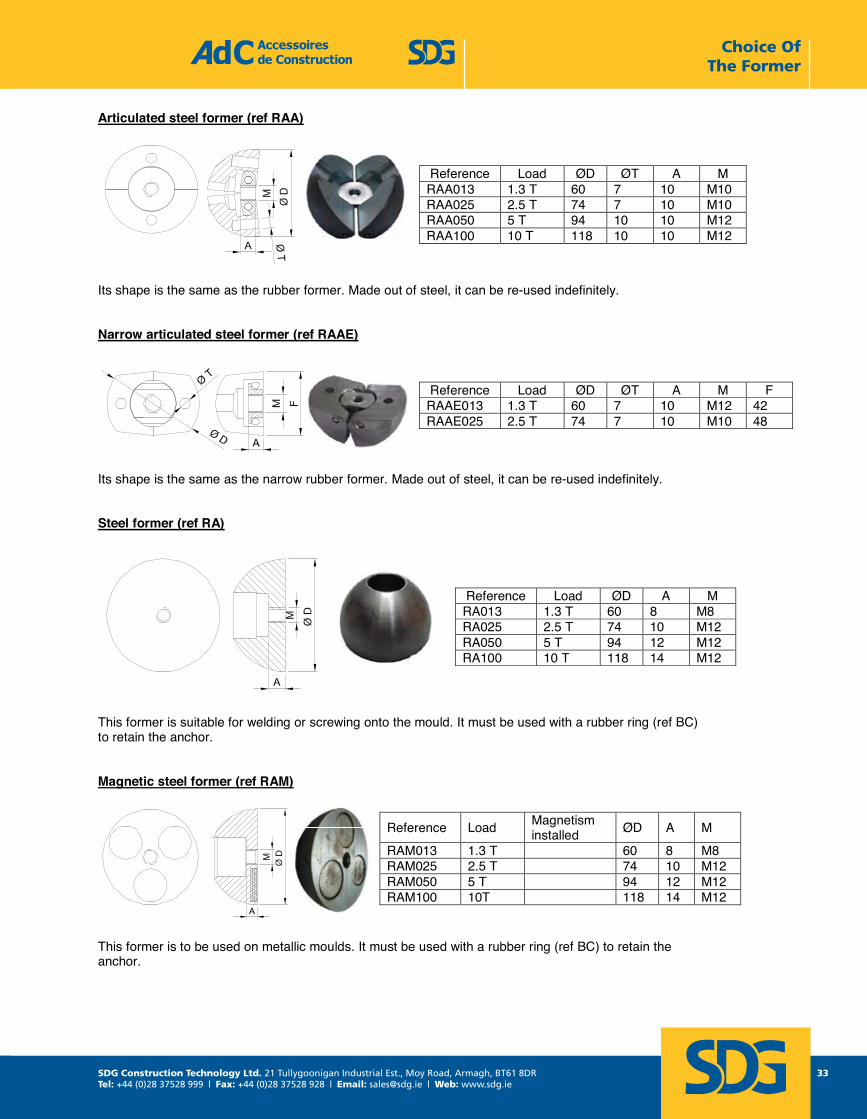
Articulated steel former (ref RAA)
Its shape is the same as the rubber former. Made out of steel, it can be re-used indefinitely.
Narrow articulated steel former (ref RAAE)
Its shape is the same as the narrow rubber former. Made out of steel, it can be re-used indefinitely.
Steel former (ref RA)
This former is suitable for welding or screwing onto the mould. It must be used with a rubber ring (ref BC) to retain the anchor.
Magnetic steel former (ref RAM)
This former is to be used on metallic moulds. It must be used with a rubber ring (ref BC) to retain the anchor.
Reference Load ØD ØT A M RAA013 1.3 T 60 7 10 M10 RAA025 2.5 T 74 7 10 M10 RAA050 5 T 94 10 10 M12 RAA100 10 T 118 10 10 M12
Reference Load ØD ØT A M F RAAE013 1.3 T 60 7 10 M12 42 RAAE025 2.5 T 74 7 10 M10 48
Reference Load ØD A M RA013 1.3 T 60 8 M8 RA025 2.5 T 74 10 M12 RA050 5 T 94 12 M12 RA100 10 T 118 14 M12
Reference Load Magnetism installed ØD A M
RAM013 1.3 T 60 8 M8 RAM025 2.5 T 74 10 M12 RAM050 5 T 94 12 M12 RAM100 10T 118 14 M12
Choice Of The Former
SDG Construction Technology Ltd. 21 Tullygoonigan Industrial Est., Moy Road, Armagh, BT61 8DRTel: +44 (0)28 37528 999 | Fax: +44 (0)28 37528 928 | Email: [email protected] | Web: www.sdg.ie
34
noitcurtsnoC ed seriosseccA Tel : +33 1 39 33 18 60 1 rue Jacques Robert Fax : +33 1 39 88 14 42 95500 LE THILLAY moc.sas-cda@cda : liam-E 43 egaPFRANCE moc.sas-cda.www 3102 erbotcO - HAL
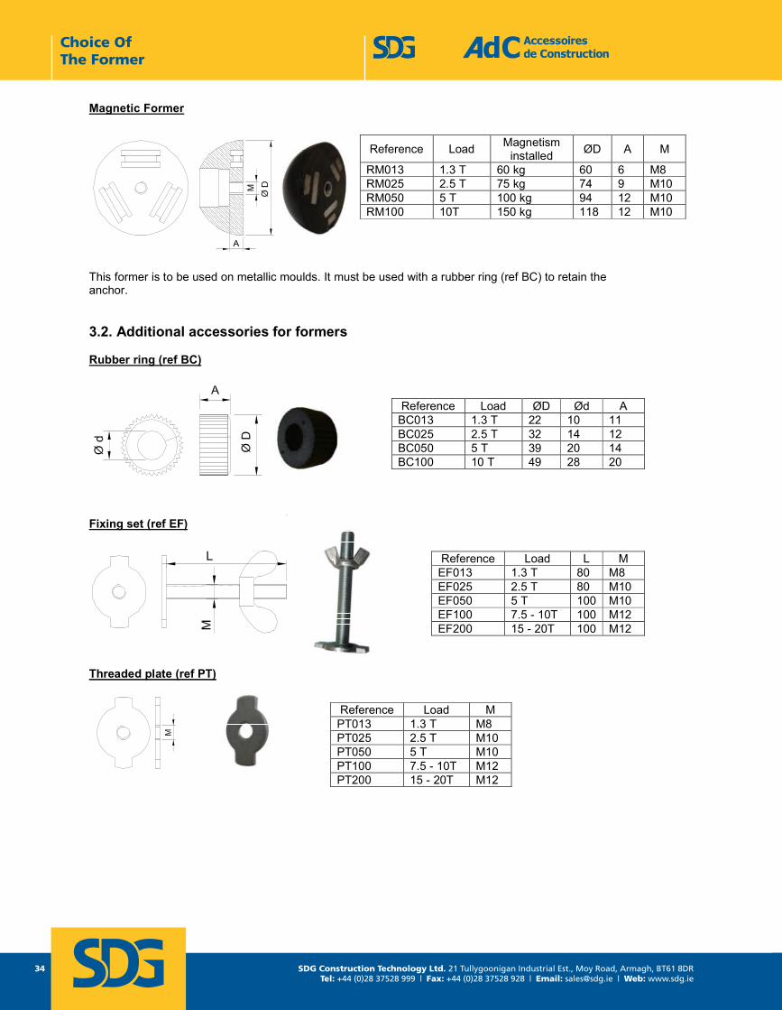
Magnetic Former
This former is to be used on metallic moulds. It must be used with a rubber ring (ref BC) to retain the anchor.
3.2. Additional accessories for formers
Rubber ring (ref BC)
Fixing set (ref EF)
Threaded plate (ref PT)
Reference Load Magnetism installed ØD A M
RM013 1.3 T 60 kg 60 6 M8 RM025 2.5 T 75 kg 74 9 M10 RM050 5 T 100 kg 94 12 M10RM100 10T 150 kg 118 12 M10
Reference Load ØD Ød A BC013 1.3 T 22 10 11 BC025 2.5 T 32 14 12BC050 5 T 39 20 14 BC100 10 T 49 28 20
Reference Load L M EF013 1.3 T 80 M8 EF025 2.5 T 80 M10 EF050 5 T 100 M10 EF100 7.5 - 10T 100 M12 EF200 15 - 20T 100 M12
Reference Load M PT013 1.3 T M8PT025 2.5 T M10 PT050 5 T M10 PT100 7.5 - 10T M12PT200 15 - 20T M12
Choice Of The Former
SDG Construction Technology Ltd. 21 Tullygoonigan Industrial Est., Moy Road, Armagh, BT61 8DRTel: +44 (0)28 37528 999 | Fax: +44 (0)28 37528 928 | Email: [email protected] | Web: www.sdg.ie
35
Accessoires de Construction Tel : +33 1 39 33 18 60 1 rue Jacques Robert Fax : +33 1 39 88 14 42 95500 LE THILLAY Page 35 E-mail : [email protected] FRANCE LAH - Octobre 2013 www.adc-sas.com
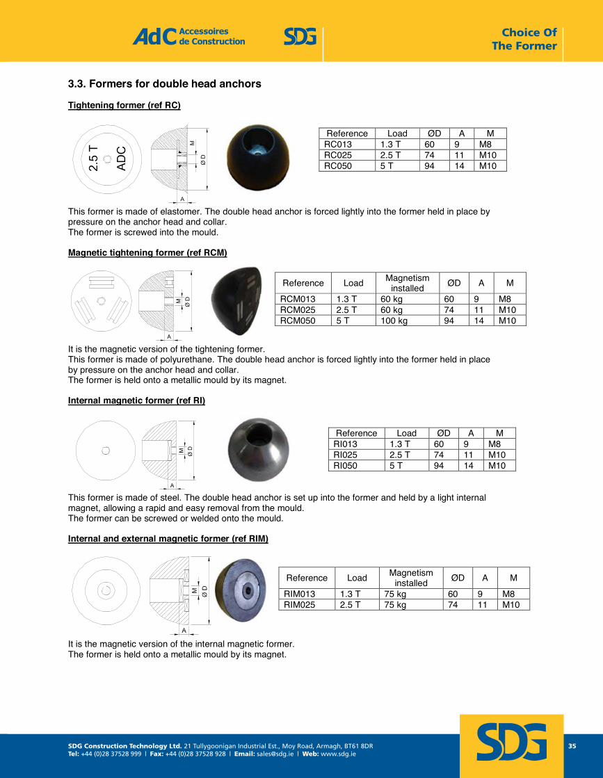
3.3. Formers for double head anchors
Tightening former (ref RC)
This former is made of elastomer. The double head anchor is forced lightly into the former held in place by pressure on the anchor head and collar. The former is screwed into the mould.
Magnetic tightening former (ref RCM)
It is the magnetic version of the tightening former. This former is made of polyurethane. The double head anchor is forced lightly into the former held in place by pressure on the anchor head and collar. The former is held onto a metallic mould by its magnet.
Internal magnetic former (ref RI)
This former is made of steel. The double head anchor is set up into the former and held by a light internal magnet, allowing a rapid and easy removal from the mould. The former can be screwed or welded onto the mould.
Internal and external magnetic former (ref RIM)
It is the magnetic version of the internal magnetic former. The former is held onto a metallic mould by its magnet.
Reference Load ØD A M RC013 1.3 T 60 9 M8 RC025 2.5 T 74 11 M10 RC050 5 T 94 14 M10
Reference Load Magnetism installed ØD A M
RCM013 1.3 T 60 kg 60 9 M8 RCM025 2.5 T 60 kg 74 11 M10RCM050 5 T 100 kg 94 14 M10
Reference Load ØD A M RI013 1.3 T 60 9 M8 RI025 2.5 T 74 11 M10 RI050 5 T 94 14 M10
Reference Load Magnetism installed ØD A M
RIM013 1.3 T 75 kg 60 9 M8 RIM025 2.5 T 75 kg 74 11 M10
Choice Of The Former
SDG Construction Technology Ltd. 21 Tullygoonigan Industrial Est., Moy Road, Armagh, BT61 8DRTel: +44 (0)28 37528 999 | Fax: +44 (0)28 37528 928 | Email: [email protected] | Web: www.sdg.ie
36
noitcurtsnoC ed seriosseccA Tel : +33 1 39 33 18 60 1 rue Jacques Robert Fax : +33 1 39 88 14 42 95500 LE THILLAY moc.sas-cda@cda : liam-E 63 egaPFRANCE moc.sas-cda.www 3102 erbotcO - HAL
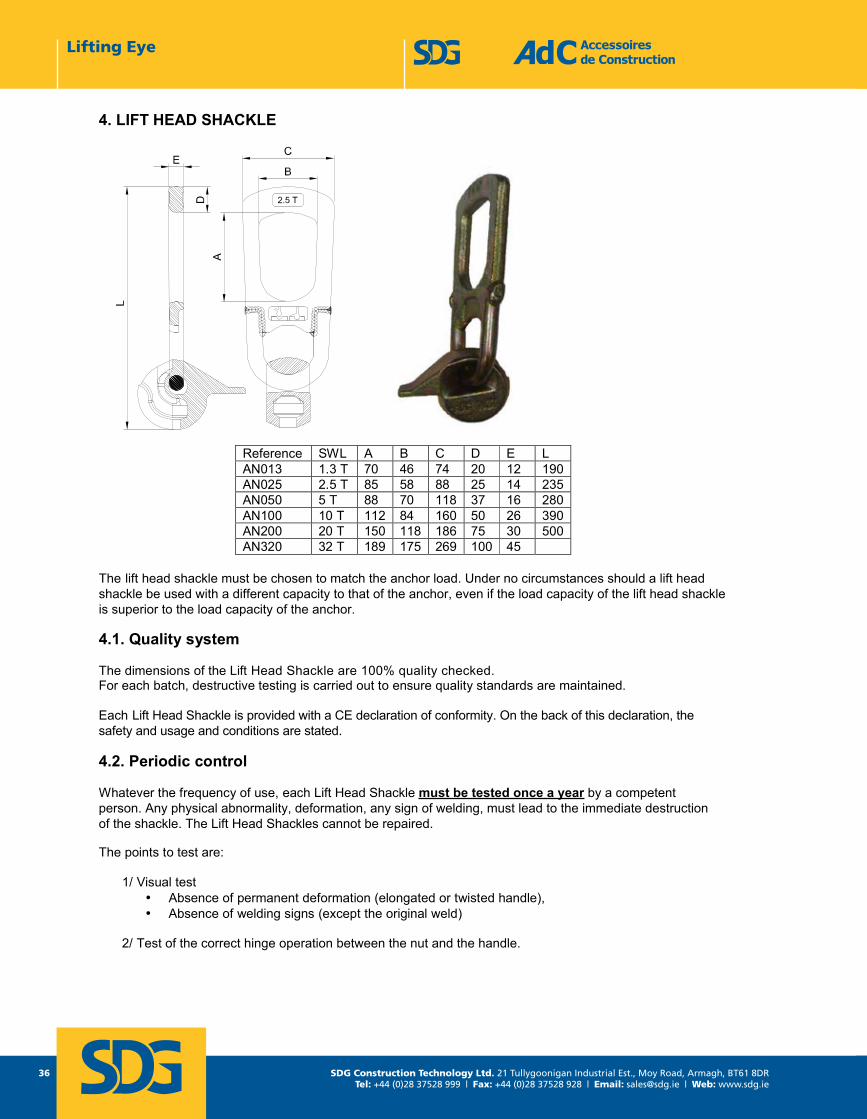
4. LIFT HEAD SHACKLE
The lift head shackle must be chosen to match the anchor load. Under no circumstances should a lift head shackle be used with a different capacity to that of the anchor, even if the load capacity of the lift head shackleis superior to the load capacity of the anchor.
4.1. Quality system
The dimensions of the Lift Head Shackle are 100% quality checked.For each batch, destructive testing is carried out to ensure quality standards are maintained.
Each Lift Head Shackle is provided with a CE declaration of conformity. On the back of this declaration, thesafety and usage and conditions are stated.
4.2. Periodic control
Whatever the frequency of use, each Lift Head Shackle must be tested once a year by a competentperson. Any physical abnormality, deformation, any sign of welding, must lead to the immediate destructionof the shackle. The Lift Head Shackles cannot be repaired.
The points to test are:
1/ Visual test • Absence of permanent deformation (elongated or twisted handle), • Absence of welding signs (except the original weld)
2/ Test of the correct hinge operation between the nut and the handle.
Reference SWL A B C D E L AN013 1.3 T 70 46 74 20 12 190AN025 2.5 T 85 58 88 25 14 235AN050 5 T 88 70 118 37 16 280AN100 10 T 112 84 160 50 26 390AN200 20 T 150 118 186 75 30 500AN320 32 T 189 175 269 100 45
Lifting Eye
SDG Construction Technology Ltd. 21 Tullygoonigan Industrial Est., Moy Road, Armagh, BT61 8DRTel: +44 (0)28 37528 999 | Fax: +44 (0)28 37528 928 | Email: [email protected] | Web: www.sdg.ie
37
noitcurtsnoC ed seriosseccA Tel : +33 1 39 33 18 60 1 rue Jacques Robert Fax : +33 1 39 88 14 42 95500 LE THILLAY moc.sas-cda@cda : liam-E 73 egaPFRANCE moc.sas-cda.www 3102 erbotcO - HAL
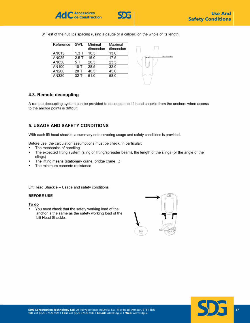
3/ Test of the nut lips spacing (using a gauge or a caliper) on the whole of its length:
4.3. Remote decoupling
A remote decoupling system can be provided to decouple the lift head shackle from the anchors when accessto the anchor points is difficult.
5. USAGE AND SAFETY CONDITIONS
With each lift head shackle, a summary note covering usage and safety conditions is provided.
Before use, the calculation assumptions must be check, in particular: • The mechanics of handling • The expected lifting system (sling or lifting/spreader beam), the length of the slings (or the angle of the
slings) • The lifting means (stationary crane, bridge crane…) • The minimum concrete resistance
Lift Head Shackle – Usage and safety conditions
BEFORE USE
To do • You must check that the safety working load of the
anchor is the same as the safety working load of the Lift Head Shackle.
Reference SWL Minimal dimension
Maximal dimension
AN013 1.3 T 10.5 13.0 AN025 2.5 T 15.0 17.5 AN050 5 T 20.5 23.5 AN100 10 T 28.5 32.0 AN200 20 T 40.5 45.0 AN320 32 T 51.0 58.0
Use And Safety Conditions
SDG Construction Technology Ltd. 21 Tullygoonigan Industrial Est., Moy Road, Armagh, BT61 8DRTel: +44 (0)28 37528 999 | Fax: +44 (0)28 37528 928 | Email: [email protected] | Web: www.sdg.ie
38
noitcurtsnoC ed seriosseccA Tel : +33 1 39 33 18 60 1 rue Jacques Robert Fax : +33 1 39 88 14 42 95500 LE THILLAY moc.sas-cda@cda : liam-E 83 egaPFRANCE moc.sas-cda.www 3102 erbotcO - HAL
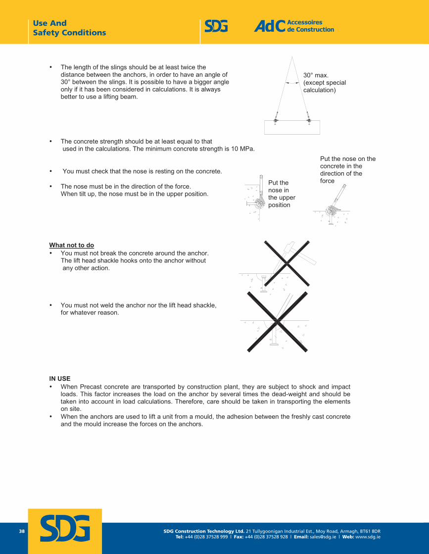
• The length of the slings should be at least twice the distance between the anchors, in order to have an angle of 30° between the slings. It is possible to have a bigger angle only if it has been considered in calculations. It is always better to use a lifting beam.
• The concrete strength should be at least equal to that used in the calculations. The minimum concrete strength is 10 MPa.
• You must check that the nose is resting on the concrete.
• The nose must be in the direction of the force. When tilt up, the nose must be in the upper position.
What not to do • You must not break the concrete around the anchor.
The lift head shackle hooks onto the anchor without any other action.
• You must not weld the anchor nor the lift head shackle, for whatever reason.
IN USE • When Precast concrete are transported by construction plant, they are subject to shock and impact
loads. This factor increases the load on the anchor by several times the dead-weight and should be taken into account in load calculations. Therefore, care should be taken in transporting the elements on site.
• When the anchors are used to lift a unit from a mould, the adhesion between the freshly cast concrete and the mould increase the forces on the anchors.
30° max. (except special calculation)
Put the nose in the upper position
Put the nose on the concrete in the direction of the force
Use And Safety Conditions
SDG Construction Technology Ltd. 21 Tullygoonigan Industrial Est., Moy Road, Armagh, BT61 8DRTel: +44 (0)28 37528 999 | Fax: +44 (0)28 37528 928 | Email: [email protected] | Web: www.sdg.ie
39
noitcurtsnoC ed seriosseccA Tel : +33 1 39 33 18 60 1 rue Jacques Robert Fax : +33 1 39 88 14 42 95500 LE THILLAY moc.sas-cda@cda : liam-E 93 egaPFRANCE moc.sas-cda.www 3102 erbotcO - HAL
MAINTENANCE • All lift head shackles must be examined once a year by a competent person. The lifting eye must not
show any sign of deformity. • The lift head shackle cannot be repaired.
GENERAL • The lift head shackle must be used only for lifting Precast concrete elements.• Users of the lift head shackle must be familiar with the usage and safety instructions.• All usage and safety instructions must be respected when lift head shackles are used.
Note :Les renseignements de cette documentation sont donnés à titre indicatif et peuvent être modifiés à tout moment sans préavis par � �� . All information in this document is just indicative information, and can be modified without prior notification from � �� .
Use And Safety Conditions

SDG Construction Technology Ltd. 21 Tullygoonigan Industrial Est., Moy Road, Armagh, BT61 8DRTel: +44 (0)28 37528 999 | Fax: +44 (0)28 37528 928 | Email: [email protected] | Web: www.sdg.ie
40 SDG Construction Technology Ltd. 21 Tullygoonigan Industrial Est., Moy Road, Armagh, BT61 8DRTel: +44 (0)28 37528 999 | Fax: +44 (0)28 37528 928 | Email: [email protected] | Web: www.sdg.ie
Note:All information in this document is just indicitive information, and can be modified without prior notification from SDG / AdC.