Embed Size (px)
Citation preview
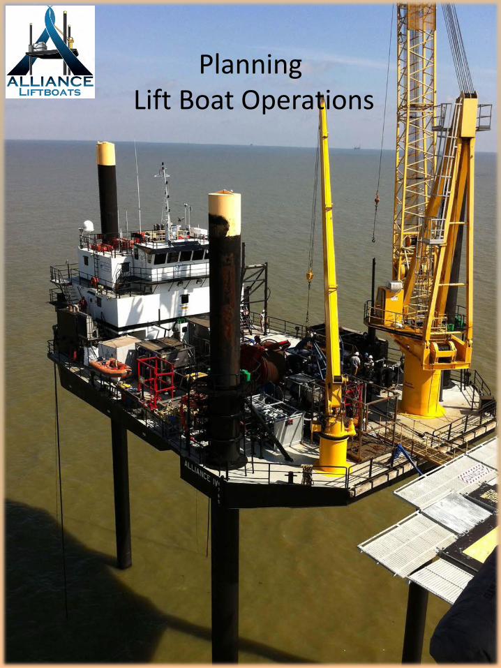
Planning Lift Boat Operations

Considerations
3. Determining vessel class: “water depth, pad penetration depth, required air gap & leg length Loss”
4. Illustration 5. Deck cargo during transit, deck cargo not allowed in transit 6. Illustration 7. Soil conditions & pre-load times 8. Sea conditions required for normal positioning & departing 9. Sea conditions required for confined space positioning and
departing 10. Mob/De-Mob. Running times 11. Base maps 12. Mesotech Sonar Positioning 13. Obstacles that will impede positioning, if not foreseen 14. Illustration 15. Illustration 16. Illustration 17. Crane swinging restrictions & affect of minimum radiuses: 18. Illustration 19. Distribution of weight 20. Excessive deck loading 21. Deck point loading & washing off weldments 22. 12/24 hour operations 23. Fuel, Potable Water & Food Consumption
Page:

Determining Vessel Class
When attempting to minimize cost with minimal support, it is critical to evaluate job location thoroughly. Considerations:
a. Water Depth b. Height of Service Deck, i.e. “Sub-Cellar Deck, Cellar Deck,
Main Deck”, where scope of work is to be performed. c. “Potential Pad Penetration”. Oversight on potential Pad
Penetration has caused more grief for project managers than any other single factor. As little as 10’ of penetration due to low density soil conditions, will drastically affect the ability to complete the scope of work.
d. As a result of the Jacking Tower Height, there is always leg loss.
a. 145’ Class -14’ b. 175’ Class -13’

Necessary water depth, pad penetration & air gap to perform scope of work
14’ Leg Length Loss as a result of Jacking Tower Height.
Mud Line @ -90’
Pad with 10’ of Penetration -100’
18’ Air Gap
ALLIANCE 145’ Class Lift Boat
Main Deck @ +26’ Elevation
8’
14’
Water Line

Deck Cargo During Transit & Deck Cargo Not Allowed During Transit
Lift Boats are regulated by USCG “Operations Manual” and Stability Curve Guidelines generated by the Designing Naval Architect. Each Lift Boat has its own “Maximum” Deck Load Capacity and Stability Curves. Considerations For loading deck cargo:
a. Equally distribute load port to starboard and fore to aft. b. Equipment to be connected by hoses must be within close proximity of each other.
c. No tanks containing fluids during transit. d. Specific equipment access requires appropriate walkway clearance between stowed items. e. Total amount of area available for stowage and fixed appendages that may render certain areas useless except for small compact items. f. Available tie down fixtures . g. Potential height restrictions in areas where crane booms rest in racks for transit. h. Deck cargo such as cantilever assemblies with coring apparatuses that may be transported with the partial assembly hanging over bow. This is evaluated on as needed basis.

Deck Cargo Stowage, Passage Ways & Weight Distribution
Cent
er L
ine
Vess
el
550,000 Lbs.
25,000 Lbs.
25,000 Lbs. Typical 30” Walkway Clearance
48” clearance where hoses Will adjoin pumps and tanks.

Soil Conditions, Pre-Load Times & Pad Retrieval
Pre-Load times will vary based on region.
a. Most Lift Boat companies maintain historical data regarding pad penetration, if historical data is not available within your archives, contact the chosen Lift Boat Operator and request pad penetration depth and estimated pre-loading times.
b. Pre-Loading begins when the Lift Boat is elevated, to a height where seas are not making contact with the bottom during pre-loading. There is really no time limit on Pre-loading. As long as the vessel’s pads continue to settle below mud line, Pre-Loading must continue. Only after each pad has reached a static state for a minimum of 2 hours, the vessel may dump it’s pre-load ballast and jack up to the required working height.
c. Throughout Pre-Load Cycles, there can be no personnel, Crew Members or Third Party Personnel on the Main Deck. Reason being, if the vessel spontaneously settles in one direction, and deck cargo shifts, personnel will not be in harms way. While Jacking all personnel except for the Captain must be outside of the quarters, with life vest on, on the 02 or wheelhouse level deck. If your location entails a prolonged pre-loading time frame, it will be beneficial to transit all third party contractors to location after pre-loading and jacking to elevation has been achieved. Otherwise all personnel will have to be standing throughout the entire process.
d. On locations where High Pad Penetration (20+ feet) is achieved, it could possibly take 24- 48 hours to retrieve pads. These conditions create additional concern during Hurricane Season. If a storm develops within the Gulf and conditions deteriorate prior to the Lift Boats ability to retrieve its pads and depart to a Safe Harbor, the vessel will be forced to remian on location with a high probability of being lost during the storm.

Sea conditions required for normal positioning & departure
Maximum sea conditions for positioning are between 3’ – 5’ depending on type and direction of sea conditions. 1. A Lift Boat will be able to position in 4’ to 5’ sea conditions, only if the direction of seas are not not impeding the captains ability to safely position the vessel around the structure and within the confinement of surrounding pipelines. 2. The Lift Boat will difficulty maintaining position and tagging down in a 3’ – 5’ Side Sea condition. 2. It is not possible for Lift Boats to approach and position on location with a trailing 3’ to 5’ sea condition. Lift Boats do not maneuver well backing to stern, against a current, prevailing wind and/or sea state including swells. Trailing Sea Condition,
pushing vessel into platform most un-desirable condition.
Head Seas Conditions, most desirable condition
Side Seas acceptable with minimal conditions
Can Holes from Drilling Rig.
Side Seas acceptable with minimal conditions

Sea conditions required for positioning onto a congested location
When precise positioning or positioning in a congested area is required, the current, wind, and sea conditions must be calm. 1. The vessel is required to stay a minimum distance of 15’ from the pipeline, off of the starboard pad. 2. There is a variable lateral and fore & aft allowance of 3’ as a result of the false rotary assembly, that is suspended over the bow 10’ to support pile driving operations. 3. The vessel must be rotated slightly towards the port, to gain more room between the Lift Boat leg and tri pod cluster, to allow for off loading piles from the support vessel.
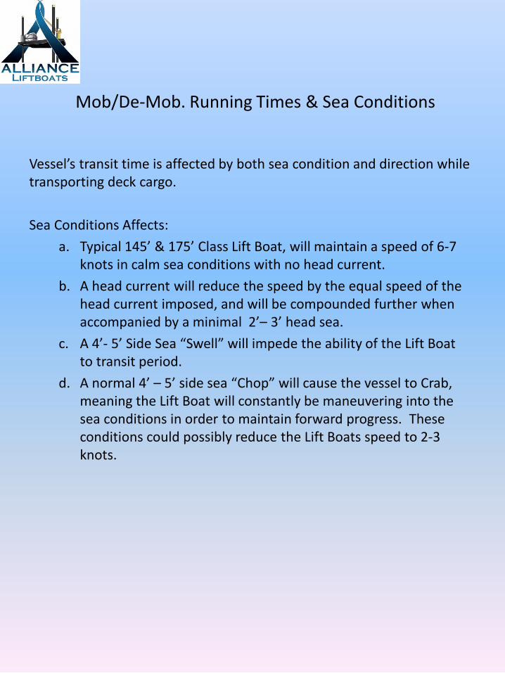
Mob/De-Mob. Running Times & Sea Conditions
Vessel’s transit time is affected by both sea condition and direction while transporting deck cargo. Sea Conditions Affects:
a. Typical 145’ & 175’ Class Lift Boat, will maintain a speed of 6-7 knots in calm sea conditions with no head current.
b. A head current will reduce the speed by the equal speed of the head current imposed, and will be compounded further when accompanied by a minimal 2’– 3’ head sea.
c. A 4’- 5’ Side Sea “Swell” will impede the ability of the Lift Boat to transit period.
d. A normal 4’ – 5’ side sea “Chop” will cause the vessel to Crab, meaning the Lift Boat will constantly be maneuvering into the sea conditions in order to maintain forward progress. These conditions could possibly reduce the Lift Boats speed to 2-3 knots.

Base Maps
There is no better way to explain informative information from inferior information, than to refer to the base maps attached below. If your survey company submits a base map, with the knowledge its for positioning a lift boat and they submit the top base map, you should be concerned. A Drilling Rig of some design drilled that well, and if a conventional drilling rig with Cans drilled your well, knowing where the Can Holes are located, is essential to keeping personnel and equipment safe. Can Holes are addressed further within.
Inferior Base Map for positioning Liftboats
Informative Base Map

Mesotech Sonar Positioning
Mesotech Sonar Survey during approach is essential when close proximity of Pipelines, Can Holes and Debris are factors. Even if the location of all the above is depicted within the Base Map, the Captain’s ability to maneuver and tag down within a close proximity of and/or stay away from any one component is impossible without Sub-Surface Sonar guiding and plotting him onto location.
Pipeline within 20’
All three pads positioned within previous liftboat Footprint, with Stern Leg center of Can Hole, with 40+ feet of penetration.
Only accomplished with Mesotech Sonar
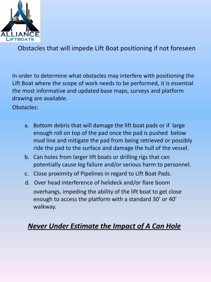
Obstacles that will impede Lift Boat positioning if not foreseen
In order to determine what obstacles may interfere with positioning the Lift Boat where the scope of work needs to be performed, it is essential the most informative and updated base maps, surveys and platform drawing are available. Obstacles:
a. Bottom debris that will damage the lift boat pads or if large enough roll on top of the pad once the pad is pushed below mud line and mitigate the pad from being retrieved or possibly ride the pad to the surface and damage the hull of the vessel.
b. Can holes from larger lift boats or drilling rigs that can potentially cause leg failure and/or serious harm to personnel.
c. Close proximity of Pipelines in regard to Lift Boat Pads. d. Over head interference of helideck and/or flare boom overhangs, impeding the ability of the lift boat to get close
enough to access the platform with a standard 30’ or 40’ walkway.
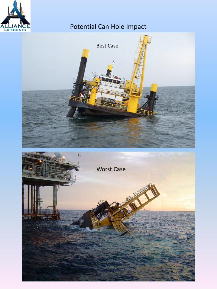
Never Under Estimate the Impact of A Can Hole

Potential Can Hole Impact
Can Hole
Scouring
Potential Area for Foundation Failure
Typical Pre-Load Elevation

Potential Can Hole Impact
Can Hole
Foundation Failure
Potential Can Hole Impact
Worst Case
Best Case

Crane capacities, swing restrictions & affects of minimum radiuses
1. Lift Boat cranes are similar to other offshore cranes with dynamic and
static rated load parameters. a. Dynamic ratings pertain to loads being lifted off of and/or onto a
floating vessel, where surges can induce dynamic motions. b. Static ratings pertain to lifts made between the Lift Boat and
platform or dockside where neither entity is realizing any dynamic motions that will cause surge.
2. Besides the Lift Boat leg, swing restrictions pertain to anything protruding from the platform that will impede the ability of the crane to offload a support vessel, once positioned. On many occasions a project manger is looking at a set of drawings that do depict all of a platforms structural overhangs. As a result the Lift Boat will arrive on location and realize the vessel can not position in the area where it was required to be.
a. Helideck overhang b. Flare Boom overhang c. Life boat launching apparatuses, etc. d. Platform crane booms
3. The lack of ability for the main crane to offload heavy equipment from a support vessel and set within a close proximity of the base of the crane is referred to as minimum radius. The Ram 100 crane on a typical 175’ Class Lift Boat has a minimum radius of 22’ from center line crane. This means the main crane can not set anything on deck of the lift boat within 22’ of the cranes center of rotation. Any support equipment placed within the 22’ minimum radius must be light enough to be lifted into position and stowed with the auxiliary crane.
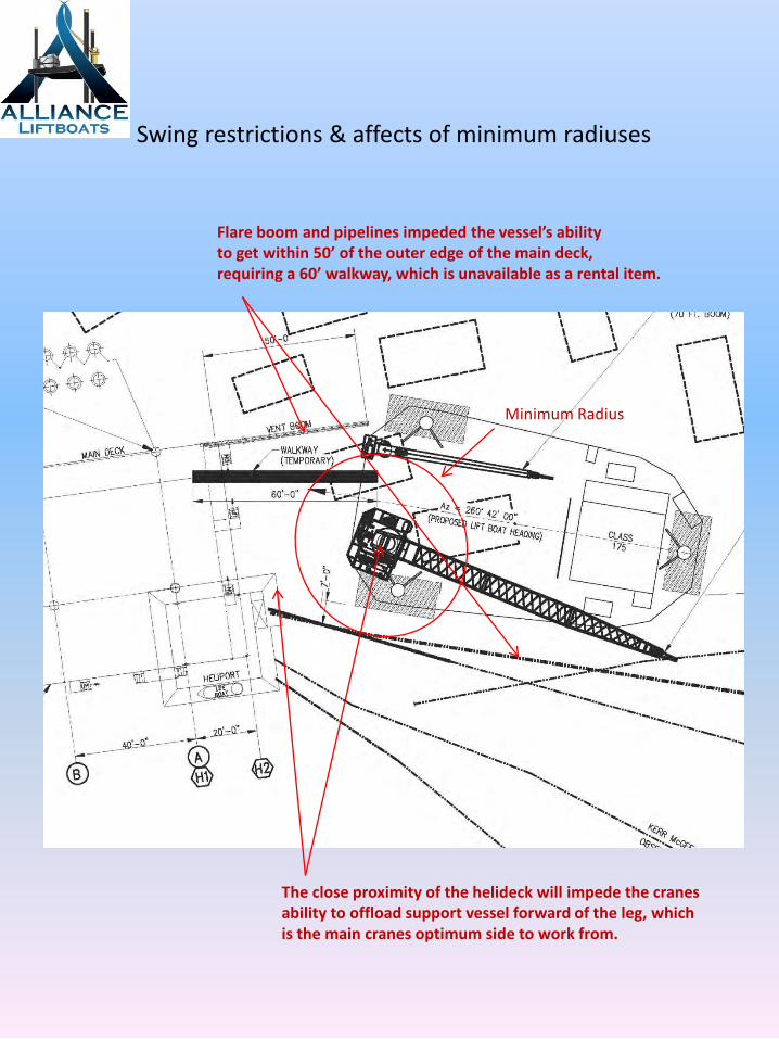
Swing restrictions & affects of minimum radiuses
Flare boom and pipelines impeded the vessel’s ability to get within 50’ of the outer edge of the main deck, requiring a 60’ walkway, which is unavailable as a rental item.
The close proximity of the helideck will impede the cranes ability to offload support vessel forward of the leg, which is the main cranes optimum side to work from.
Minimum Radius

Distribution of weight
1. Managing the distribution of deck loading throughout the project is essential. a. A high emphasis must be placed on the arrangement of large capacity
storage tanks, that will be filled once on location. The Captain of the Lift Boat will load his vessel according to stability curves prescribed within the vessel’s operations manual, taking into consideration the tank will be filled once jacked up on location. The Captain’s guidelines for placement of the tank may not coincide with the project managers proposed layout, regarding equipment flow. It is always a good practice to forward a proposed equipment layout to the lifeboat operations department for review, prior to committing to your layout.
22K 22K
12K
12K 12K
12K
12K
12K
12K 12K
12K 12K
6K
12K
27K
24K
7K 3K 5K
4K
2K
3K
127,000 Lbs. Starboard Side of Center Line
130,000 Lbs. Port Side of Center Line
High Capacity Tanks, weights depicted as Full of Fluids

Excessive Deck Loading & Deck Point Loading
27,000 Lb. Pile Sections supported by 8’ x 8’ triple laminated 2” Wooden Load Spreaders. Pile and hammer will be up-righted on load spreaders to mitigate damage to deck plate and/or internal framing.
Pile Driving Hammer supported by 8’ x 8’ triple laminated 2” Wood Load Spreaders.
2. Excessive Deck Loading & Point Loading is easily accomplished on all Lift Boats. Common deck plate thickness is ¼” with very light internal scantlings (framing).
a. Heavy Support Equipment and/or Structural Components that will require
upending and/or laying over on deck of the Lift Boat which can not be lifted and manipulated with two cranes, must be accompanied by some type of load spreaders.
b. If such Support Equipment and/or Structural Components arrive location without being accompanied by Load Spreaders, the flow of the project could easily be interrupted as a result.
Note: The pile lifting pad eyes are positioned to where the Crane Operator, will up end the pile by raising the load, booming up and swinging to his right, inherently, increased hook height as a result.

Removal of Tie Down Brackets
Removing Support Equipment, Tie Down Brackets welded to the deck.
a. Most Contract Welders who have history of cutting away tie down brackets and/or doubler plates know the deck material on liftboats are very thin. With that said the general practice of removing these appendages, is to wash the majority of the weldment off, leaving approximately ¼” of weldment on the deck. Once the Bracket and/or Doubler Plate has been removed, the remaining weldment will be ground off flush with the deck surface. If the welder attempts to torch wash the weldment off and penetrates the deck plate by accident, UCSG & LLOYDS Registry will require that an 18” x 18” cut out and insert be performed. If the welder Knicks the deck and leaves a divot, the divot will have to be re-filled 100% and ground flush with the deck surface.
Tie Down Brackets
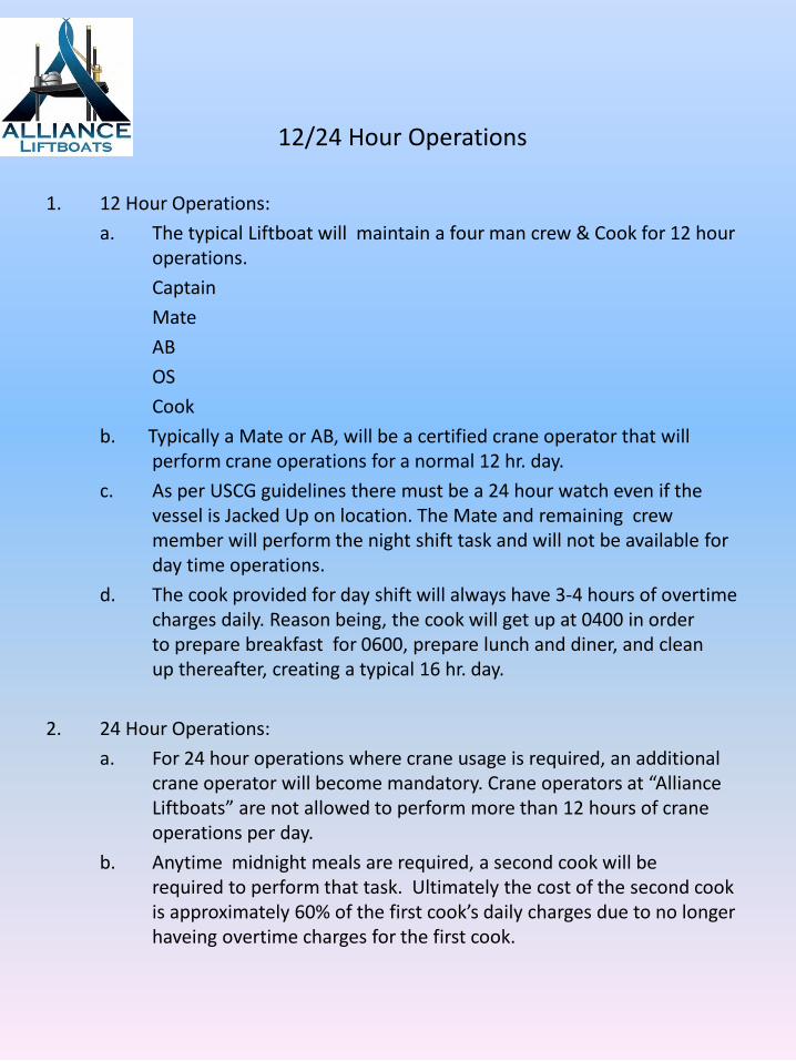
12/24 Hour Operations
1. 12 Hour Operations: a. The typical Liftboat will maintain a four man crew & Cook for 12 hour
operations. Captain Mate AB OS Cook b. Typically a Mate or AB, will be a certified crane operator that will
perform crane operations for a normal 12 hr. day. c. As per USCG guidelines there must be a 24 hour watch even if the
vessel is Jacked Up on location. The Mate and remaining crew member will perform the night shift task and will not be available for day time operations.
d. The cook provided for day shift will always have 3-4 hours of overtime charges daily. Reason being, the cook will get up at 0400 in order to prepare breakfast for 0600, prepare lunch and diner, and clean up thereafter, creating a typical 16 hr. day.
2. 24 Hour Operations: a. For 24 hour operations where crane usage is required, an additional
crane operator will become mandatory. Crane operators at “Alliance Liftboats” are not allowed to perform more than 12 hours of crane operations per day.
b. Anytime midnight meals are required, a second cook will be required to perform that task. Ultimately the cost of the second cook is approximately 60% of the first cook’s daily charges due to no longer haveing overtime charges for the first cook.

Consumables Fuel, Lube, Water & Groceries
Consumables: a. Fuel & Lube only becomes a problem for ongoing projects that last
more than 10 days. Most Lift Boats can maintain station even with excessive Crane Utilization for a ten day period without re-fueling.
b. Potable Water becomes the most important and consumed product on board. Average consumption per a person is approximately 40-50 gallons Per day, when you add in laundry, toilets, showers, vessel machinery demands, and galley consumption.
1. 15 third party contractors = 600-750 gallons per day 2. 5 Vessel Crew & Cook = 200-250 gallons per day 3. Vessel Machinery Demands = approximately 200 gallons per day 4. Total average consumption = 1,000-1200 per day 5. 145’ Class Potable water capacity 9,800 gallons = 6.5-8 days w/1800
gallons of reserve. 6. 175’ Class Potable Water capacity 13,600 gallons = 10-12 days
w/1,600 gallons of reserve. c. If you want to insure your offshore contractors are fed to standards that
promotes positive attitudes and keeps moral up, you want to re-supply groceries every seven days. Beyond this time frame milk, bread and perishables become difficult to keep fresh and the poor quality of food begins to deteriorate attitudes and moral.