Embed Size (px)
Citation preview
Lifetime Extension of Higher Class UHF RFIDTags using special Power Management
Techniques and Energy Harvesting Devices
Alex Janek12, Christian Steger1, Josef Preishuber-Pfluegl2 and MarkusPistauer2
1 Institute for Technical Informatics, Graz University of TechnologyInffeldgasse 16/1, 8010 Graz, AUSTRIA
janek,[email protected] CISC Semiconductor Design&Consulting GmbH
Lakeside B07, 9020 Klagenfurt, AUSTRIAj.preishuber-pfluegl,[email protected]
Abstract. Enhanced RFID tag technology especially in the UHF fre-quency range provides extended functionality like high operating rangeand sensing and monitoring capabilities. Such functionality requiringextended system structures including data acquisition units, real timeclocks and active transmitters causes a high energy consumption of thetag and requires an on board energy store (battery). As a key parameterof the reliability of an RFID system is the lifetime, the energy budgetof the higher class tag has to be as balanced as possible. This can beachieved by using energy harvesting devices as additional power supply.The PowerTag 1 project and thus this paper proposes special power man-agement mechanisms in combination with special energy storage struc-tures interfacing energy harvesting devices and dealing with their specialrequirements. First various power management and power saving tech-niques are simulated and their performance is evaluated. In a secondstep different implementation variants of energy storage structures arecompared by using accurate simulation models of the various parts of thesystem. The results are compared to manufacturer given and guaranteedsystem performance parameters of a state-of-the-art higher class UHFRFID system. The presented approach combines two simulations for thedesign and the evaluation of different tag architectures and power savingtechniques. Simulation results are showing an improvement of over 44%of achievable lifetime applying the power saving techniques and powersubsystem architectures presented in this paper, compared to a state-of-the-art higher class system.
Keywords. Higher Class UHF RFID, Energy harvesting, Energy stor-age architectures, Lifetime extension
1 This project has been supported by Austrian government under the grant number811854
Dagstuhl Seminar Proceedings 07041Power-aware Computing Systemshttp://drops.dagstuhl.de/opus/volltexte/2007/1104

2 A. Janek, C. Steger, J. Preishuber-Pfluegl, M. Pistauer
1 Introduction
The next generation of UHF RFID tags (called higher class UHF RFID tags -HCT [1]) provides extended functionality in terms of independent sensing andmonitoring, high communication range and large memory areas. This requirescontinue operation of the tag itself - also if it is not powered by the reader asin formerly pure passive UHF RFID systems [2]. Thus an on-board energy sup-ply is necessary, which forces a renaming of the previously called passive UHFRFID technology to semi-passive and active technology. This change in the tagarchitecture pushes new issues in the area of UHF RFID; the operational life-time, which is limited by the on-board energy reservoir and thus the need oflong time power saving techniques. The energy, which is stored on a tag is lim-ited by the state-of-the-art energy storage technology and so even with profoundpower saving techniques the achievable lifetime is often dissatisfying. The way tosolve this issue is to supply energy from the environment by energy harvestingdevices. As the energy converted by such devices comes from the environment,it is generally unpredictable, non-continues and unstable special energy storagearchitectures are necessary to deal with this particular requirements, which arepresented in the following sections. The difference between semi-passive and ac-tive technology is the tag to reader communication. Semi-passive UHF RFIDtags provide extended functionality as mentioned before but the communicationis based on the same passive method as passive UHF RFID tags simply reflect-ing and modulating the reader signal. The operating range of such tags is muchhigher, as the reader signal is used for the communication only but not for pow-ering the whole tag like in pure passive RFID [2]. The communication from tagto reader of active UHF RFID tags is based on an active on-tag communicationunit (transmitter), which generates a carrier frequency and modulates it. Thedifference between the two technologies is the achievable operating range, whichis much higher using active UHF RFID technology. This technology additionallyis similar to sensor nodes; the difference is that an active RFID system is hierar-chically controlled by a central reader whereby the principle of a sensor networkis the cooperative (multihob) communication between sensor nodes mostly onthe same hierarchical level. The constraints for both active RFID and sensornode systems are similar for many parameters as shown in [3]; cited literatureis often based on sensor node technology as more research has been done in thisfield.
1.1 System structure of higher class UHF RFID Tags
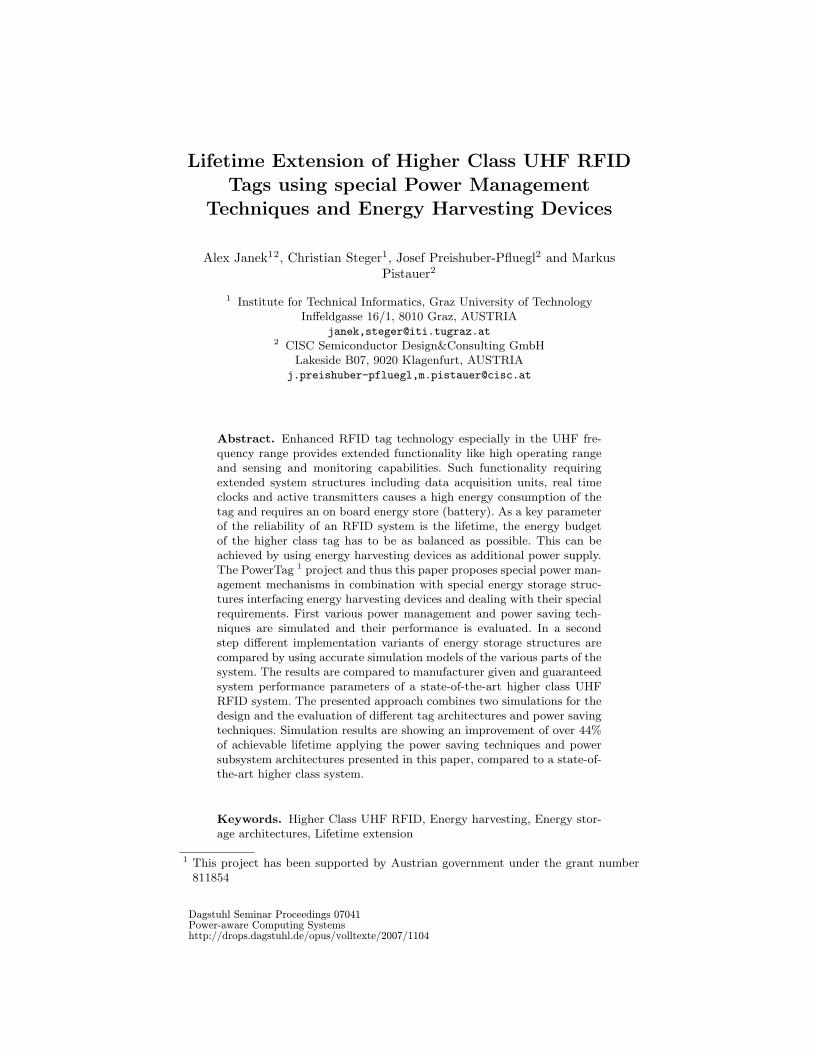
The system structure of a higher class UHF RFID tag consists of several func-tional blocks as shown at Figure 1. This figure shows the structure of an activeUHF RFID tag as an example for a higher class tag. The structure can rawlybe divided into three different subsystems: the power and scheduling subsystem,the communication and data processing subsystem and the sensing subsystem.
Lifetime Extension of Higher Class UHF RFID Tags powered by EHD 3
Fig. 1. Higher class tag architecture - Example: active UHF RFID tag
1.2 Energy harvesting
As the mentioned extended functionality of a HCT implies high energy consump-tion, the key goal for achieving a long lifetime is the optimization of the energybudget of the tag. As this is not possible using single use batteries without re-placing them frequently, the target is to use additional energy sources (energyharvesting devices - EHD) to support the on board supply. As the energy con-verted by energy harvesting devices comes from the environment, it is generallyunstable, unpredictable and non-continuous. This requires special power man-agement principles and energy storage structures, which have strong impact onthe structure of a higher class tag.
1.3 Related work
The study [4] shows key issues and possible solutions on using solar cells as anenergy harvesting device for a sensor node and thus extending the lifetime ofthe whole system. This study shows that a device including an efficient energymanagement in combination with a high reliable energy storage and an energyharvesting device is able to operate near-perpetual.
Table 1 is taken from a study [5] and compares energy storage structures andenergy harvesting devices in different aspects.
In [6] special energy storage structures are presented, which use environmen-tal radio frequency fields for powering mobile phones. The key goal of the projectwas to design an energy storage structure being able to convert the scavengedvery low power to a level, which can be used to charge the phones batteries. In [7]an energy storage structure including a rechargeable battery interfacing a solarcell as a power supply for a sensor node (Heliomote) is shown and the achievedperformance is analyzed. In [8] and [9] several measurements and theoretical con-siderations are showing, that the energy provided by energy harvesting devices

4 A. Janek, C. Steger, J. Preishuber-Pfluegl, M. Pistauer
Power Source P/cm3 E/cm3 P/cm3/Year(µ W/cm3) (J/cm3) (µ W/cm3/Jr)
Primary Bat - 2280 90
Secondary Bat - 1080 34
Micro-Fuel Cell - 3500 110
Ultra-capacitor - 50-100 1.6-3.2
Heat engine - 3346 106
Radioactive (Ni63) 0.52 1640 0.52
Solar (outside) 15000 - -
Solar (inside) 10 - -
Temperature 40 - -
Human Power 330 - -
Air flow 380 - -
Pressure Variation 17 - -
Vibrations 200 - -
Table 1. Comparison of the reliability of energy harvesting devices
is mostly unstable, hart do predict and non-continues. Depending on the envi-ronmental energy, which is converted, the variation time period of the providedamount of energy varies between milliseconds and days.
2 Problem analysis: power consumption of higher classtags
As the operation lifetime of higher class tags depends heavily on the energyavailable in the energy store, a profound and accurate power management man-aging the power consumption in an intelligent way as well as being able to givea feedback about the expected remaining lifetime is one of the key factors defin-ing the quality of a higher class tag. To define power management policies andfind improvable parameters, the analysis of the energy consumption of the mostimportant parts of the tag is necessary.
2.1 Power consumption of a HCT - Example
This section describes such an evaluation of a state-of-the-art active UHF RFIDtag to find leading energy consumption factors and blocks. The following table(Table 2) shows a long-run evaluation of the energy consumption of a HCT on theexample of an active RFID tag from Identec Solutions [10]. This measurementwas done for the time period of a day (24 hours). The temperature logging wasactivated and set to the interval of 1 minute whereby the related active RFIDreader requested the last temperature sample once each hour.
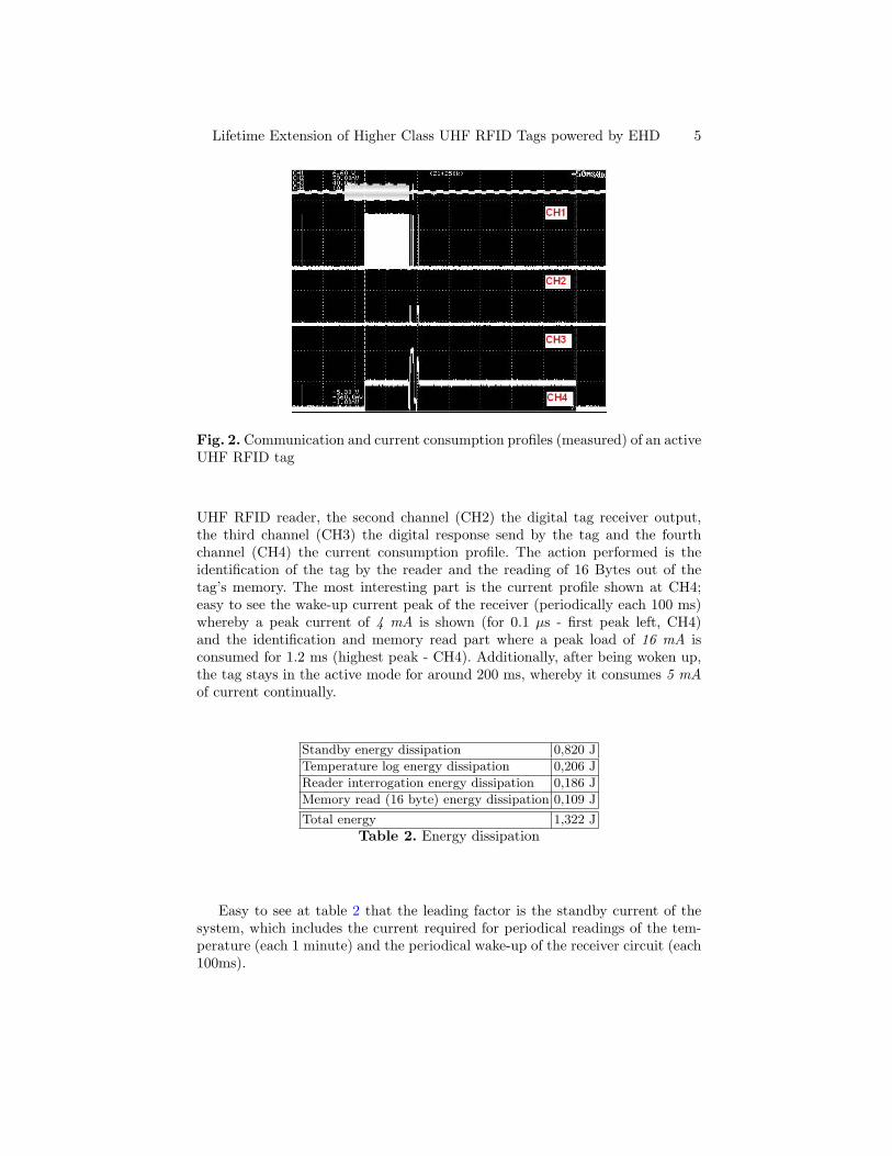
Figure 2 shows the measured power consumption profile for the identificationprocess (450 ms) for a higher class tag (active tag from Identec Solutions [10]).The first channel (CH1) shows the command send by the corresponding active
Lifetime Extension of Higher Class UHF RFID Tags powered by EHD 5
Fig. 2. Communication and current consumption profiles (measured) of an activeUHF RFID tag
UHF RFID reader, the second channel (CH2) the digital tag receiver output,the third channel (CH3) the digital response send by the tag and the fourthchannel (CH4) the current consumption profile. The action performed is theidentification of the tag by the reader and the reading of 16 Bytes out of thetag’s memory. The most interesting part is the current profile shown at CH4;easy to see the wake-up current peak of the receiver (periodically each 100 ms)whereby a peak current of 4 mA is shown (for 0.1 µs - first peak left, CH4)and the identification and memory read part where a peak load of 16 mA isconsumed for 1.2 ms (highest peak - CH4). Additionally, after being woken up,the tag stays in the active mode for around 200 ms, whereby it consumes 5 mAof current continually.
Standby energy dissipation 0,820 J
Temperature log energy dissipation 0,206 J
Reader interrogation energy dissipation 0,186 J
Memory read (16 byte) energy dissipation 0,109 J
Total energy 1,322 J
Table 2. Energy dissipation
Easy to see at table 2 that the leading factor is the standby current of thesystem, which includes the current required for periodical readings of the tem-perature (each 1 minute) and the periodical wake-up of the receiver circuit (each100ms).
6 A. Janek, C. Steger, J. Preishuber-Pfluegl, M. Pistauer
Although the current flow is small, it is consumed continually and so it hasa significant impact on the tags lifetime. The proposed solution described in thefollowing sections reduces this current by introducing power saving techniques(e.g. special wake-up procedures) in combination wit the use of energy harvestingdevices.
2.2 Energy harvesting devices
Generally speaking a energy harvesting device converts energy from the envi-ronment into electrical energy. This fits to the most important and commonsources as mechanical energy (vibrations - piezo generator), solar light (solarcells), thermal energy (temperature differences - thermo generator) as well as toless common sources like electromagnetic energy (RF sensor).
Piezo generator The piezo generator is based on the piezoelectric effect wherebypiezoelectric materials are deformed on the presence of an electromagnetic fieldand conversely produce an electromagnetic charge if they are deformed [11].
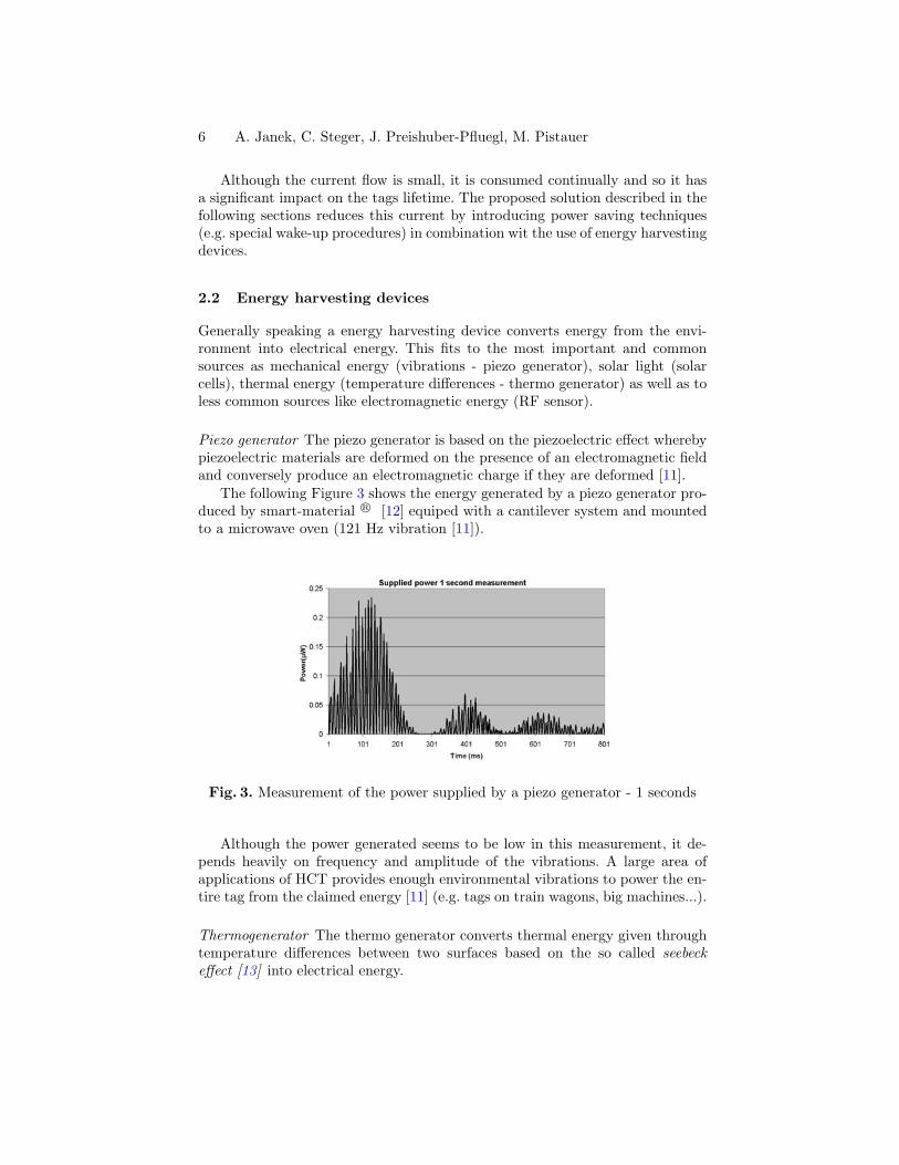
The following Figure 3 shows the energy generated by a piezo generator pro-duced by smart-material R© [12] equiped with a cantilever system and mountedto a microwave oven (121 Hz vibration [11]).
Fig. 3. Measurement of the power supplied by a piezo generator - 1 seconds
Although the power generated seems to be low in this measurement, it de-pends heavily on frequency and amplitude of the vibrations. A large area ofapplications of HCT provides enough environmental vibrations to power the en-tire tag from the claimed energy [11] (e.g. tags on train wagons, big machines...).
Thermogenerator The thermo generator converts thermal energy given throughtemperature differences between two surfaces based on the so called seebeckeffect [13] into electrical energy.
Lifetime Extension of Higher Class UHF RFID Tags powered by EHD 7
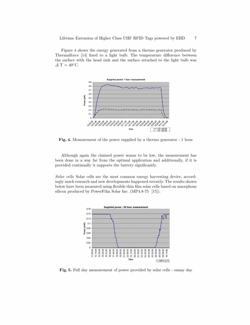
Figure 4 shows the energy generated from a thermo generator produced byThermalforce [14] fixed to a light bulb. The temperature difference betweenthe surface with the head sink and the surface attached to the light bulb was∆ T = 40◦C.
Fig. 4. Measurement of the power supplied by a thermo generator - 1 hour
Although again the claimed power seams to be low, the measurement hasbeen done in a way far from the optimal application and additionally, if it isprovided continually it supports the battery significantly.
Solar cells Solar cells are the most common energy harvesting device, accord-ingly much research and new developments happened recently. The results shownbelow have been measured using flexible thin film solar cells based on amorphoussilicon produced by PowerFilm Solar Inc. (MP4.8-75 [15]).
Fig. 5. Full day measurement of power provided by solar cells - sunny day
8 A. Janek, C. Steger, J. Preishuber-Pfluegl, M. Pistauer
3 Novel power management strategies for battery-drivenhigher class tags supported by energy harvestingdevices
This section deals with special power saving techniques, which allow to savepower on the one side but even to utilize power provided by the reader on theother side.
3.1 Sleep state transition - wake up control
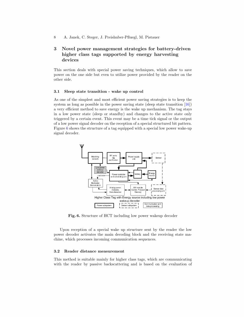
As one of the simplest and most efficient power saving strategies is to keep thesystem as long as possible in the power saving state (sleep state transition [16])a very efficient method to save energy is the wake up mechanism. The tag staysin a low power state (sleep or standby) and changes to the active state onlytriggered by a certain event. This event may be a time tick signal or the outputof a low power signal decoder on the reception of a special structured bit pattern.Figure 6 shows the structure of a tag equipped with a special low power wake-upsignal decoder.
Fig. 6. Structure of HCT including low power wakeup decoder
Upon reception of a special wake up structure sent by the reader the lowpower decoder activates the main decoding block and the receiving state ma-chine, which processes incoming communication sequences.
3.2 Reader distance measurement
This method is suitable mainly for higher class tags, which are communicatingwith the reader by passive backscattering and is based on the evaluation of
Lifetime Extension of Higher Class UHF RFID Tags powered by EHD 9
the distance between tag and reader. This may be done simply measuring thestrength of the received reader signal (carrier) or evaluating the distance withcomplex and accurate distance evaluation mechanisms.
The idea is that depending on the distance between tag and reader, threedifferent operating modes can be defined.
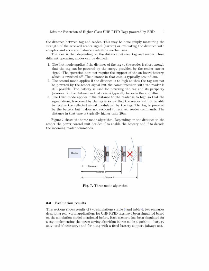
1. The first mode applies if the distance of the tag to the reader is short enoughthat the tag can be powered by the energy provided by the reader carriersignal. The operation does not require the support of the on board battery,which is switched off. The distance in that case is typically around 5m.
2. The second mode applies if the distance is to high so that the tag can notbe powered by the reader signal but the communication with the reader isstill possible. The battery is used for powering the tag and its periphery(sensors...). The distance in that case is typically between 8m and 20m.
3. The third mode applies if the distance to the reader is to high so that thesignal strength received by the tag is so low that the reader will not be ableto receive the reflected signal modulated by the tag. The tag is poweredby the battery but it does not respond to received reader commands. Thedistance in that case is typically higher than 20m.
Figure 7 shows the three mode algorithm. Depending on the distance to thereader the power control unit decides if to enable the battery and if to decodethe incoming reader commands.
Fig. 7. Three mode algorithm
3.3 Evaluation results
This sections shows results of two simulations (table 3 and table 4; two scenariosdescribing real world applications for UHF RFID tags have been simulated basedon the simulation model mentioned before. Each scenario has been simulated fora tag implementing the power saving algorithm (three mode algorithm - batteryonly used if necessary) and for a tag with a fixed battery support (always on).

10 A. Janek, C. Steger, J. Preishuber-Pfluegl, M. Pistauer
Use case 1 - Container shipment: The first scenario describes the shipmentof containers equipped with HCT. During the simulated shipment process of 4weeks, different readers are trying to inventory the tag on the container 50 times.This happens as an example 10 times by a reader directly near the tag (shortdistance, < 5m), 20 times in a middle distance (around 20m) and 20 times outof the communication range (long distance, > 20m - the tag is not inventoried).Additionally the tag measures the current temperature each 6 hours and storesthe value in its memory. Those values are read out by readers 68 times; 10 timesin a short distance, 18 times in a middle distance and 50 times from a longdistance (no communication is possible).
Table 3 shows the results of the simulation of scenario 1, the container ship-ment.
Algorithm EEPROM FRAM
Battery always on 1,409Ws 27,5µWsReader distance measurement 1,38Ws 23,0µWs(Three mode algorithm)
Table 3. Scenario 1: Container shipment
As visible there is no big difference in the energy supplied by the batterybetween the simulation of a tag implementing the three mode algorithm and thesimulation without this algorithm. The reason is that most of the time the tagis not in a reader field and so the battery has to supply the whole energy for thelogging mechanism.
Use case 2 - Public transport access control: The second scenario describespublic transport access control and booking. The simulated time is 1 year and itcan be assumed that due to mechanical restrictions (gate construction) the tagis always within the range where a communication with the reader is possible.It is assumed that the tag reader communicates 600 times with the tag (nearly2 times per day) reading and adjusting the account balance. It is assumed thatthe communication happens 300 times with the tag near the reader (< 5m) and300 times in the weak field (< 20m).
Table 4 shows the results of the simulation of scenario 2, the public transportaccess control.
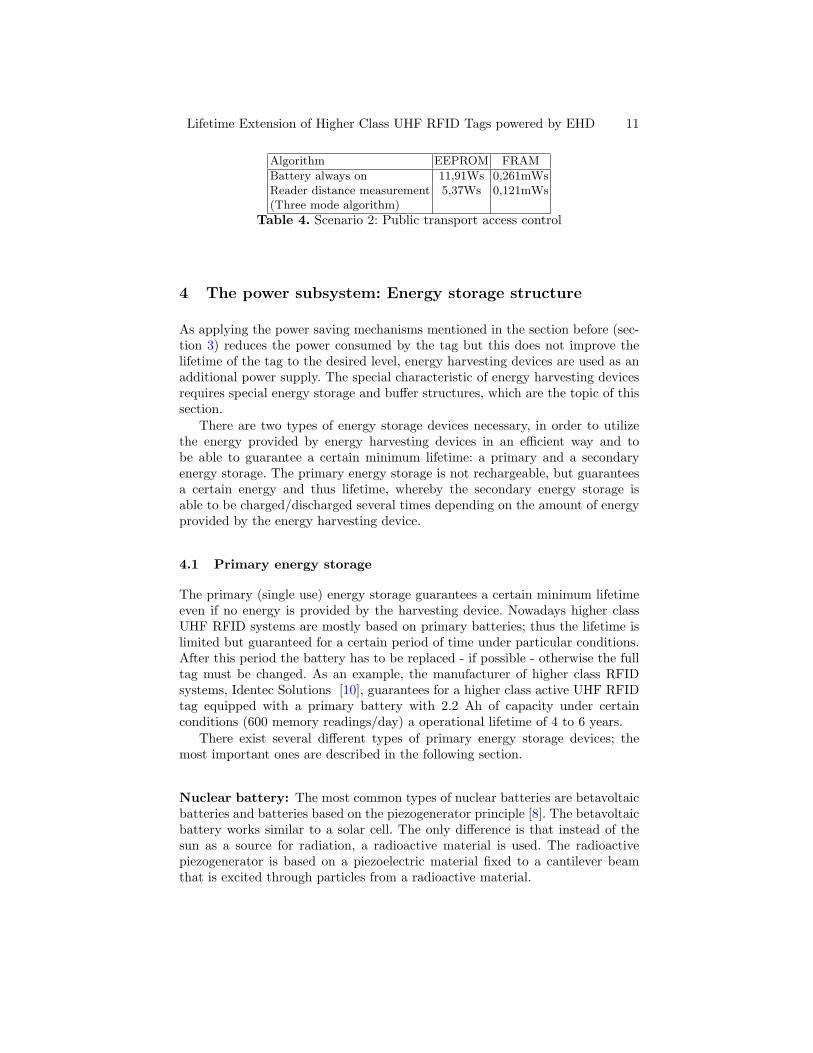
As visible a significant amount of energy supplied by the battery can besaved if the capability of the reader of providing the necessary power to thetag is evaluated. This affects mainly applications where a high percentage ofthe total communication processes happens in a short distance between tag andreader.
The simulation results have shown that a simple mechanism under certainconditions allows to save around 50% of the power consumed from the tagsbattery.
Lifetime Extension of Higher Class UHF RFID Tags powered by EHD 11
Algorithm EEPROM FRAM
Battery always on 11,91Ws 0,261mWsReader distance measurement 5,37Ws 0,121mWs(Three mode algorithm)
Table 4. Scenario 2: Public transport access control
4 The power subsystem: Energy storage structure
As applying the power saving mechanisms mentioned in the section before (sec-tion 3) reduces the power consumed by the tag but this does not improve thelifetime of the tag to the desired level, energy harvesting devices are used as anadditional power supply. The special characteristic of energy harvesting devicesrequires special energy storage and buffer structures, which are the topic of thissection.
There are two types of energy storage devices necessary, in order to utilizethe energy provided by energy harvesting devices in an efficient way and tobe able to guarantee a certain minimum lifetime: a primary and a secondaryenergy storage. The primary energy storage is not rechargeable, but guaranteesa certain energy and thus lifetime, whereby the secondary energy storage isable to be charged/discharged several times depending on the amount of energyprovided by the energy harvesting device.
4.1 Primary energy storage
The primary (single use) energy storage guarantees a certain minimum lifetimeeven if no energy is provided by the harvesting device. Nowadays higher classUHF RFID systems are mostly based on primary batteries; thus the lifetime islimited but guaranteed for a certain period of time under particular conditions.After this period the battery has to be replaced - if possible - otherwise the fulltag must be changed. As an example, the manufacturer of higher class RFIDsystems, Identec Solutions [10], guarantees for a higher class active UHF RFIDtag equipped with a primary battery with 2.2 Ah of capacity under certainconditions (600 memory readings/day) a operational lifetime of 4 to 6 years.
There exist several different types of primary energy storage devices; themost important ones are described in the following section.
Nuclear battery: The most common types of nuclear batteries are betavoltaicbatteries and batteries based on the piezogenerator principle [8]. The betavoltaicbattery works similar to a solar cell. The only difference is that instead of thesun as a source for radiation, a radioactive material is used. The radioactivepiezogenerator is based on a piezoelectric material fixed to a cantilever beamthat is excited through particles from a radioactive material.

12 A. Janek, C. Steger, J. Preishuber-Pfluegl, M. Pistauer
Type Betavoltaic battery Nuclear piezogenerator
Material Ni-63 Ni-63
Half life 100 years 100 years
Power 150 nW @ 100 mCurie 15 µW @ 0.5 mCurie
Table 5. Battery capacity, material and lifetime of nuclear batteries
Electrochemical cells: The most common primary (non-rechargeable) electro-chemical battery types used in portable electric devices and consumer electronicsare: Zinc-Carbon, Alkaline-Manganese Dioxide and Lithium. The working prin-ciple is similar to all types, the difference is the energy density, voltage per celland the sensitivity against environmental impacts [17].
Microcells: Microcells or microbatteries are based on the same working princi-ple as standard-size electrochemical cells. However, the used materials are differ-ent. Due to the reduced size the capacity is significantly reduced, limiting theirapplicability to very low power applications.
4.2 Secondary energy storage
The secondary (rechargeable) energy storage fulfills two main tasks. It deals withthe special requirements of energy harvesting devices being charged on a surplusof environmental energy and being discharged on lack of environmental energy.Additionally, it buffers current peaks generated by the higher class tag. Twomain types of secondary energy stores are described in the following section.
Electrochemical capacitors: Electrochemical capacitors are capacitors withhigh energy density. These properties come from an electrochemical double-layerand the use of high conductivity materials as well as from the large surface areaof the electrodes, which is achieved by using porous materials [18]. Differencesbetween an ultracapacitor and a rechargeable battery are the nearly unlimitedcycle life and the fact, that ultracapacitors have nearly no negative battery effectsapart from a high self discharge rate [18,19,20].
Electrochemical cells/microbatteries: The working principle of recharge-able (secondary) electrochemical cells is similar to the single use (primary) typesas described in section 4.1 and 4.1 but the materials are different.
5 Novel power subsystem architectures for higher classtags
The following sections show two possible implementation variants of the energystorage architecture, which will be compared in the simulation subsequently. Ta-ble 6 and table 7 are pointing out different advantages/disadvantages of the im-plementation variants. Variant 0 describes the higher class tag directly connected
Lifetime Extension of Higher Class UHF RFID Tags powered by EHD 13
to a primary battery and is used in the simulation as reference implementationto show related improvements.
5.1 Variant 1 with two ultracapacitors as secondary energy storage
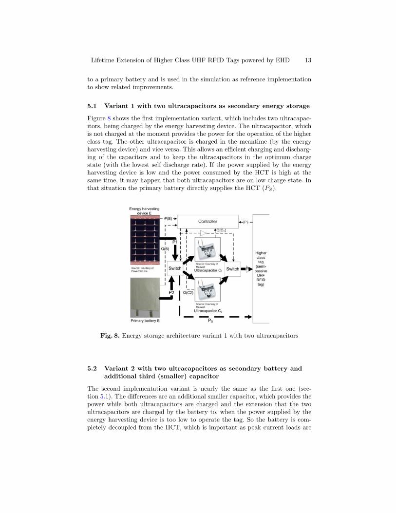
Figure 8 shows the first implementation variant, which includes two ultracapac-itors, being charged by the energy harvesting device. The ultracapacitor, whichis not charged at the moment provides the power for the operation of the higherclass tag. The other ultracapacitor is charged in the meantime (by the energyharvesting device) and vice versa. This allows an efficient charging and discharg-ing of the capacitors and to keep the ultracapacitors in the optimum chargestate (with the lowest self discharge rate). If the power supplied by the energyharvesting device is low and the power consumed by the HCT is high at thesame time, it may happen that both ultracapacitors are on low charge state. Inthat situation the primary battery directly supplies the HCT (PS).
Fig. 8. Energy storage architecture variant 1 with two ultracapacitors
5.2 Variant 2 with two ultracapacitors as secondary battery andadditional third (smaller) capacitor
The second implementation variant is nearly the same as the first one (sec-tion 5.1). The differences are an additional smaller capacitor, which provides thepower while both ultracapacitors are charged and the extension that the twoultracapacitors are charged by the battery to, when the power supplied by theenergy harvesting device is too low to operate the tag. So the battery is com-pletely decoupled from the HCT, which is important as peak current loads are
14 A. Janek, C. Steger, J. Preishuber-Pfluegl, M. Pistauer
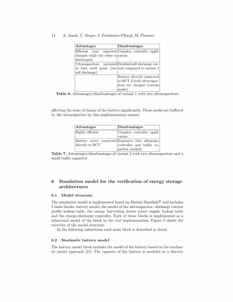
Advantages Disadvantages
Efficient (one capacitorcharged while the other isdischarged)
Complex controller appli-cation
Ultracapacitors operatedin best work point (lowself discharge)
Doubled self discharge cur-rent compared to variant 1
Battery directly connectedto HCT if both ultracapac-itors are charged (currentpeaks)
Table 6. Advantages/disadvantages of variant 1 with two ultracapacitors
affecting the state of charge of the battery significantly. Those peaks are bufferedby the ultracapacitor by this implementation variant.
Advantages Disadvantages
Highly efficient Complex controller appli-cation
Battery never connecteddirectly to HCT
Expensive (two ultracaps,controller and buffer ca-pacitor needed)
Table 7. Advantages/disadvantages of variant 2 with two ultracapacitors and asmall buffer capacitor
6 Simulation model for the verification of energy storagearchitectures
6.1 Model structure
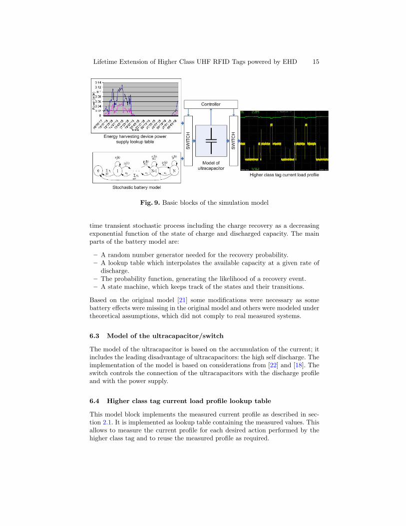
The simulation model is implemented based on Matlab Simulink R© and includes5 main blocks: battery model, the model of the ultracapacitor, discharge currentprofile lookup table, the energy harvesting device power supply lookup tableand the charge/discharge controller. Each of those blocks is implemented as abehavioral model of the block in the real implementation. Figure 9 shows theoverview of the model structure.
In the following subsections each main block is described in detail.
6.2 Stochastic battery model
The battery model block includes the model of the battery based on the stochas-tic model approach [21]. The capacity of the battery is modeled as a discrete
Lifetime Extension of Higher Class UHF RFID Tags powered by EHD 15
Fig. 9. Basic blocks of the simulation model
time transient stochastic process including the charge recovery as a decreasingexponential function of the state of charge and discharged capacity. The mainparts of the battery model are:
– A random number generator needed for the recovery probability.– A lookup table which interpolates the available capacity at a given rate of
discharge.– The probability function, generating the likelihood of a recovery event.– A state machine, which keeps track of the states and their transitions.
Based on the original model [21] some modifications were necessary as somebattery effects were missing in the original model and others were modeled undertheoretical assumptions, which did not comply to real measured systems.
6.3 Model of the ultracapacitor/switch
The model of the ultracapacitor is based on the accumulation of the current; itincludes the leading disadvantage of ultracapacitors: the high self discharge. Theimplementation of the model is based on considerations from [22] and [18]. Theswitch controls the connection of the ultracapacitors with the discharge profileand with the power supply.
6.4 Higher class tag current load profile lookup table
This model block implements the measured current profile as described in sec-tion 2.1. It is implemented as lookup table containing the measured values. Thisallows to measure the current profile for each desired action performed by thehigher class tag and to reuse the measured profile as required.
16 A. Janek, C. Steger, J. Preishuber-Pfluegl, M. Pistauer
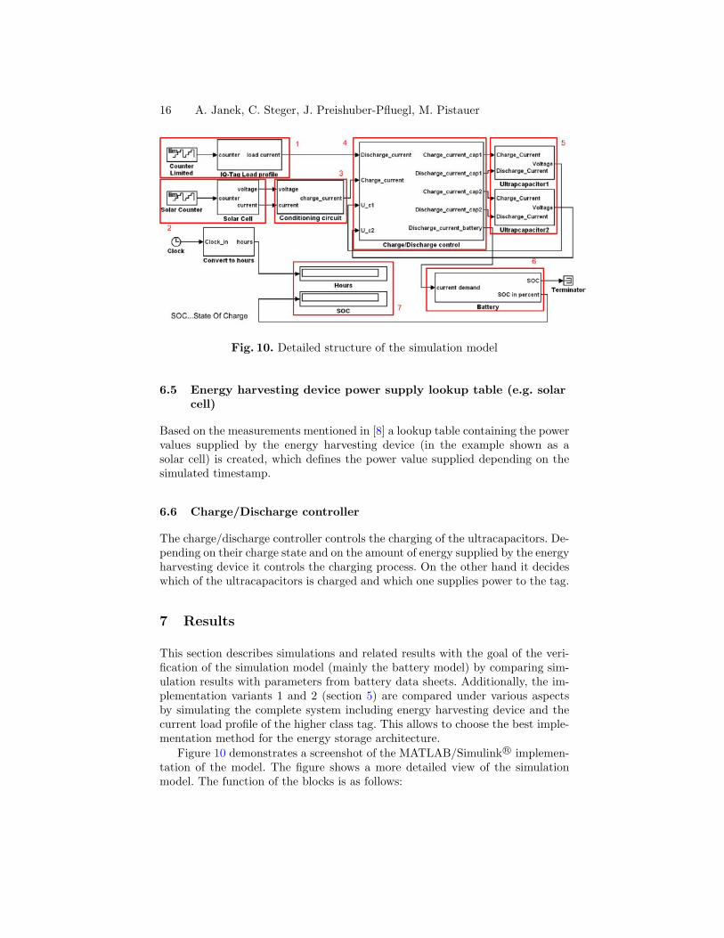
Fig. 10. Detailed structure of the simulation model
6.5 Energy harvesting device power supply lookup table (e.g. solarcell)
Based on the measurements mentioned in [8] a lookup table containing the powervalues supplied by the energy harvesting device (in the example shown as asolar cell) is created, which defines the power value supplied depending on thesimulated timestamp.
6.6 Charge/Discharge controller
The charge/discharge controller controls the charging of the ultracapacitors. De-pending on their charge state and on the amount of energy supplied by the energyharvesting device it controls the charging process. On the other hand it decideswhich of the ultracapacitors is charged and which one supplies power to the tag.
7 Results
This section describes simulations and related results with the goal of the veri-fication of the simulation model (mainly the battery model) by comparing sim-ulation results with parameters from battery data sheets. Additionally, the im-plementation variants 1 and 2 (section 5) are compared under various aspectsby simulating the complete system including energy harvesting device and thecurrent load profile of the higher class tag. This allows to choose the best imple-mentation method for the energy storage architecture.
Figure 10 demonstrates a screenshot of the MATLAB/Simulink R© implemen-tation of the model. The figure shows a more detailed view of the simulationmodel. The function of the blocks is as follows:

Lifetime Extension of Higher Class UHF RFID Tags powered by EHD 17
1. Current load profile lookup table: This block contains the measured currentload profile, which is used as load current in the model.
2. Solar cell: This block contains the power supply lookup table; a solar cell asexample energy harvesting device has been measured for 24h.
3. Conditioning circuit: This is a simple implementation of a DC/DC converter.4. Capacitor charge control: This block is the implementation of the controller.
It monitors the charge state of the single ultracapacitor and charges it byusing the battery or the solar cell.
5. Ultracapacitor: This block contains a simple model of the ultracapacitor.6. Battery:This block contains the modified stochastic model of the battery as
mentioned in section 6.2.7. These two displays are showing the simulation results: the simulated number
of hours and the corresponding charge state of the battery.
7.1 Verification of the battery model
The verification of the correctness of the implementation of the battery model hasbeen done comparing two simulation scenarios with two measurement scenarios,which are mentioned in the datasheet of the simulated battery (SonnenscheinLithium SL760 battery [23]). The first scenario is the pulse discharge behaviorwith a predefined pulse discharge profile and the second scenario the constantcurrent discharge scenario. Table 8 compares simulation results with relateddatasheet values. The pulse discharge profile is composed of periodical currentpulses of 140 mA with a duration of 10 s, 6 times per hour. This is the worstcase assumption whereby the battery lifetime has been simulated and measured.For the constant current discharge profile the discharge current has been set to60 µA.
Dischargeprofile
Simulatedoperatingtime
datasheetvalue
Error
140 mA peakpulse profile
663 h 690 h 3.9 %
60 µA con-stant current
30.833 h 30.833 h 0 %
Table 8. Simulation results - verification
As shown at table 8 comparing the simulated operating time with the datasheetvalues, the accuracy of the simulation is very high.
7.2 Comparison of variant 1 and variant 2
This simulation has been done with the model including the full target system;the energy harvesting device power supply lookup table (power profile of a solar
18 A. Janek, C. Steger, J. Preishuber-Pfluegl, M. Pistauer
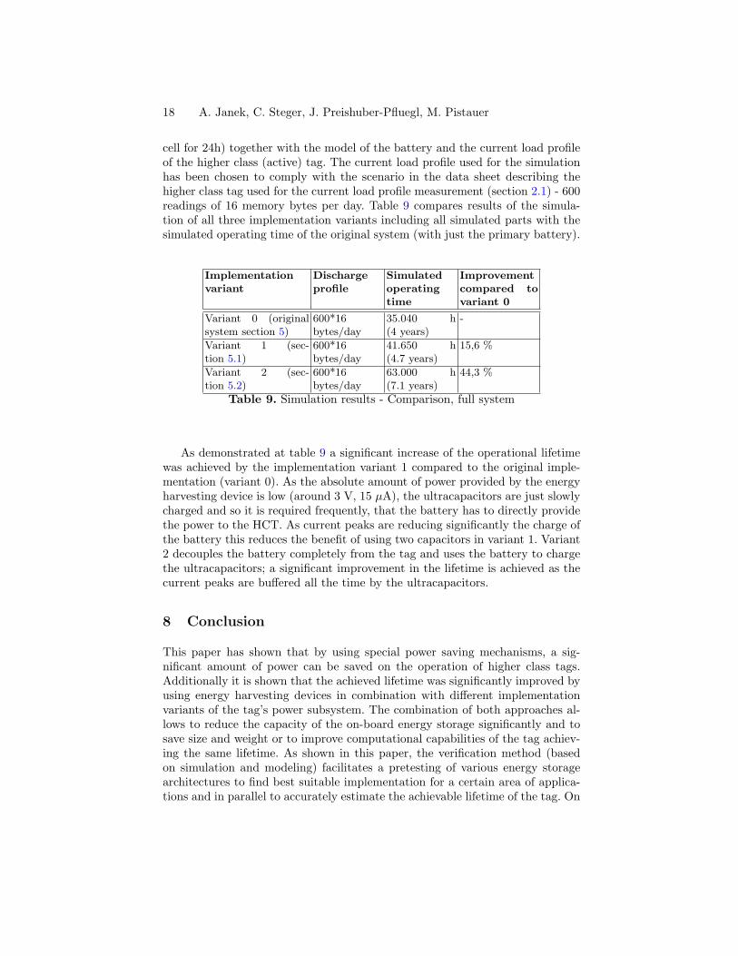
cell for 24h) together with the model of the battery and the current load profileof the higher class (active) tag. The current load profile used for the simulationhas been chosen to comply with the scenario in the data sheet describing thehigher class tag used for the current load profile measurement (section 2.1) - 600readings of 16 memory bytes per day. Table 9 compares results of the simula-tion of all three implementation variants including all simulated parts with thesimulated operating time of the original system (with just the primary battery).
Implementationvariant
Dischargeprofile
Simulatedoperatingtime
Improvementcompared tovariant 0
Variant 0 (originalsystem section 5)
600*16bytes/day
35.040 h(4 years)
-
Variant 1 (sec-tion 5.1)
600*16bytes/day
41.650 h(4.7 years)
15,6 %
Variant 2 (sec-tion 5.2)
600*16bytes/day
63.000 h(7.1 years)
44,3 %
Table 9. Simulation results - Comparison, full system
As demonstrated at table 9 a significant increase of the operational lifetimewas achieved by the implementation variant 1 compared to the original imple-mentation (variant 0). As the absolute amount of power provided by the energyharvesting device is low (around 3 V, 15 µA), the ultracapacitors are just slowlycharged and so it is required frequently, that the battery has to directly providethe power to the HCT. As current peaks are reducing significantly the charge ofthe battery this reduces the benefit of using two capacitors in variant 1. Variant2 decouples the battery completely from the tag and uses the battery to chargethe ultracapacitors; a significant improvement in the lifetime is achieved as thecurrent peaks are buffered all the time by the ultracapacitors.
8 Conclusion
This paper has shown that by using special power saving mechanisms, a sig-nificant amount of power can be saved on the operation of higher class tags.Additionally it is shown that the achieved lifetime was significantly improved byusing energy harvesting devices in combination with different implementationvariants of the tag’s power subsystem. The combination of both approaches al-lows to reduce the capacity of the on-board energy storage significantly and tosave size and weight or to improve computational capabilities of the tag achiev-ing the same lifetime. As shown in this paper, the verification method (basedon simulation and modeling) facilitates a pretesting of various energy storagearchitectures to find best suitable implementation for a certain area of applica-tions and in parallel to accurately estimate the achievable lifetime of the tag. On
Lifetime Extension of Higher Class UHF RFID Tags powered by EHD 19
the other hand it allows to test the performance of various application specificpower saving mechanisms. The approach presented in this paper combines twosimulations to design and evaluate different tag architectures and power savingtechniques. Simulation results have shown an improvement of 44% of achievableoperational time compared to a state-of-the-art higher class system aplying thepower saving techniques and power subsystem architectures presented in thispaper.
References
1. EPCglobal Inc : EPC Radio-Frequency Identity Protocols Class-1 Generation-2UHF RFID Protocol for Communications at 860 MHz 960 MHz Version 1.1.0.(2007) 8–9
2. Finkenzeller, K.: RFID handbook: fundamentals and applications incontactless smart cards and identification. Second edn. John Wileyand Sons, New York, NY, USA; London, UK; Sydney,Australia (2003)http://www.loc.gov/catdir/toc/wiley031/2002192439.html.
3. Bilstrup, U., Wiberg, P.: An architecture comparison between a wireless sensornetwork and an active rfid system. Halmstad University (2005)
4. Raghunathan, V., Kansal, A., Hsu, J., Friedman, J., Srivastava, M.: Design Consid-erations for Solar Energy Harvesting Wireless Embedded Systems. In: InformationProcessing in Sensor Networks, 2005. IPSN 2005. (2005) 457 – 462
5. Roundy, S., Steingart, D., Frechette, L., Wright, P., Rabaey, J.: Power sources forwireless sensor networks. Australian National University, Engineering Department,AUSTRALIA (2004)
6. Harrist, D.: Wireless Battery Charging System using Radio Frequency EnergyHarvesting. University of Pittsburgh, 2001 (2001)
7. Raghunathan, V., Kansal, A., Hsu, J., Friedman, J., Srivastava, M.: Design Consid-erations for Solar Energy Harvesting Wireless Embedded Systems. In: Universityof California, Los Angeles, CA 90095. (2005)
8. Janek, A., Steger, C., Preishuber-Pfluegl, J., Pistauer, M.: Power ManagementStrategies for Battery-driven Higher Class UHF RFID Tags Supported by EnergyHarvesting Devices. In: AUTOID2007, IEEE Workshop on Automatic Identifica-tion Advanced Technologies, Alghero, Italy. (2007)
9. Paradiso, J., Starner, T.: Energy scavenging for mobile and wireless electronics.In: IEEE Pervasive Computing. (2005) 18–27
10. Identec Solutions GmbH: (Active UHF RFID system)http://www.identecsolutions.com.
11. Roundy, S.: Energy scavenging for wireless sensor nodes with a focus on vibrationto electricity conversion. B.S.(Brigham Young University) 1996, M.S. (Universityof California, Berkerley) 2001 (2001)
12. Smart Material GmbH: (Advanced Piezo Composites) http://www.smart-material.com.
13. Pollok, D.D.: Thermoelectricity - Theory, Thermometry, Tool. ASTM Interna-tional (1985)
14. thermalforce.de: (Thermogenerators) http://thermalforce.de.15. PowerFilm Solar Inc.: (Thin flexible solar panels)
http://www.powerfilmsolar.com/.
20 A. Janek, C. Steger, J. Preishuber-Pfluegl, M. Pistauer
16. Sinha, A., Chandrakasan, A.: Dynamic power management in wireless sensor net-works. Massachusetts Institute of Technology, IEEE Design & Test of Computers2001 (2001)
17. Linden, D., Reddy, T.B.: Handbook of batteries. Third edn. McGraw-Hill edition(2002)
18. Bullard, G.L., Sierra-Alcazar, H., Lee, H.L., Morris, J.L.: Operating principles ofthe ultracapacitor. In: IEEE Transactions on magnetics, vol 25. (1989) 102–106
19. Zheng, C.: High pulse power system through engineering battery-capacitor combi-nation. In: IECEC International Energy Conversion Engineering Conference andExhibit, 2000. (2000)
20. Koetz, R., Carlen, M.: Principles and Applications of Electrochemical Capacitors.In: Electrochimica Acta 45,2000. (2000) 24832498
21. Panigrahi, D., Chiasserini, C., Dey, S., Rao, R., Raghunathan, A., Lahiri, K.: Bat-tery life estimation of mobile embedded systems. In: VLSI Design, 2001. FourteenthInternational Conference on. (2001) 57–63
22. Joeri, V.M., V.d.Bossche, P., Maggetto, G.: Models of energy sources for EV andHEV: fuel cells, batteries, ultracapacitors, flywheels and engine-generators. In:Journal of Power Sources 128. (2004) 76 – 89
23. Sonnenschein Lithium GmbH: (Sonnenschein lithium batteries)http://www.sonnenschein-lithium.de/.


![Reading of UHF band passive RFID tags using a reflectorap-s.ei.tuat.ac.jp/isapx/2011/pdf/[FrD4-5] A14_1005.pdfReading of UHF band passive RFID tags using a reflector #Yuki Oowashi](https://img.pdfslide.us/doc/110x75/5fe5f65925c7f35d9b27fe6b/reading-of-uhf-band-passive-rfid-tags-using-a-reflectorap-seituatacjpisapx2011pdffrd4-5.jpg)