Embed Size (px)
Citation preview

Liebert® ITA2 UPSCompact, Efficient & Robust UPS for Critical Applications 5-20kW/kVA GUIDE SPECIFICATIONS
Vertiv | Liebert® ITA2TM UPS 1 Guide Specifications | V02 | 11.2.18
Contents
1.0 GENERAL ............................................................................................................................................ 3
1.1 Summary ....................................................................................................................................... 3
1.2 STANDARDS................................................................................................................................ 3
1.3 SYSTEM DESCRIPTION ............................................................................................................. 4
1.3.1 Design Requirements ........................................................................................................... 4
1.3.2 Modes of Operation .............................................................................................................. 5
1.3.3 Performance Requirements ................................................................................................. 6
1.3.4 Input .................................................................................................................................... 6
1.3.5 AC Output .............................................................................................................................. 7
1.3.6 Grounding .............................................................................................................................. 8
1.4 ENVIRONMENTAL CONDITIONS ............................................................................................. 8
1.5 SUBMITTALS............................................................................................................................... 9
1.5.1 Proposal Submittals ............................................................................................................. 9
1.5.2 Order Submittals ................................................................................................................... 9
1.5.3 UPS Delivery Submittals ...................................................................................................... 9
1.6 WARRANTY ................................................................................................................................. 9
1.6.1 UPS Warranty ........................................................................................................................ 9
1.6.2 Warranty – End User ............................................................................................................. 9
1.7 QUALITY ASSURANCE .............................................................................................................10
1.7.1 Manufacturer’s Qualifications ............................................................................................10
1.7.2 Factory Testing ....................................................................................................................10
2.0 Product………………………………………………………………………………………………………………………..………….11 2.1 FABRICATION ......................................................................................................................11
2.1.1 Materials ...................................................................................................................................11
2.1.2 UPS Internal Wiring .................................................................................................................11
2.1.3 Field Wiring ..............................................................................................................................11
2.1.4 Construction and Mounting ............................................................................................11
2.1.5 Cooling ..................................................................................................................................11
2.2 Equipment .............................................................................................................................11
2.2.1 UPS System ..........................................................................................................................11
Vertiv | Liebert® ITA2TM UPS 2 Guide Specifications | V02 | 11.2.18
2.2.2 Surge Protection ..............................................................................................................11
2.2.3 Output Protection ............................................................................................................12
2.3 Components .........................................................................................................................12
2.3.1 Rectifier .................................................................................................................................12
2.3.2 DC-DC Converter .............................................................................................................12
2.3.3 Inverter ..............................................................................................................................13
2.3.4 Inverter Bypass Operation ..............................................................................................14
2.3.5 Display and Controls .......................................................................................................14
2.3.6 Self-Diagnostics ...............................................................................................................16
2.3.7 Remote Monitoring and Integration Capabilities .........................................................16
2.3.8 Battery Plant .....................................................................................................................16
2.3.9 Optional Accessories and Features ...............................................................................17
3.0 EXECUTION……………………………………………………………………………………………………………………………17 3.1 FIELD QUALITY CONTROL ................................................................................................18
3.2 UNIT STARTUP ....................................................................................................................18
3.3 MANUFACTURER’S FIELD SERVICE .................................................................................19
Vertiv | Liebert® ITA2TM UPS 3 Guide Specifications | V02 | 11.2.18
Liebert® ITA2TM UPS Compact, Efficient & Robust UPS for Critical Applications
5-20kW/kVA GUIDE SPECIFICATIONS
1.0 GENERAL
1.1 Summary
These specifications describe requirements for a tower or rack mounted Digital Uninterruptible Power Supply (UPS). The UPS shall automatically maintain AC power within specified tolerances to the critical load, without interruption (for specified duration as per battery run time), during failure or deterioration of the mains power supply. The UPS system shall be expandable to provide redundancy or load growth requirements.
The manufacturer shall design and furnish all materials and equipment to be fully compatible with electrical, environmental and space conditions at the site. The UPS shall include all equipment to properly interface the AC power source to the intended load and shall be designed for unattended operation.
1.2 STANDARDS
The UPS and all associated equipment and components shall be manufactured in accordance with the following applicable standards:
The UPS is CE marked in accordance with EEC directives 73/23 “low voltage” and 89/336 “electromagnetic compatibility”. The Quality System for the engineering and manufacturing facility certificated to conform to
General safety requirements for UPS EN62040-1/IEC62040-1
EMC requirements for UPS EN62040-2/IEC62040-2 (Class C2)
Method of specifying the performance
and test requirements of UPS EN62040-3/IEC62040-3(VFI SS 111)
safety of information technology
equipment, including electrical business
equipment
EN60950
Electromagnetic compatibility (EMC) IEC 61000-3-4, IEC 61000-4-2,4,5,6,8,11
Moisture and dust test
Factory certified. (Or)
GB/T 2423.21-2008 Environmental testing for electrical and
electronic products- Part 2: Test methods- Test M: low air
pressure High Altitude test
Energy star certified
2011/65/EU uninterruptible power supplies version 1.0 program
requirements/ENERGY STAR UPS version 1.0 test method
guidance
Vehicle-carrying test
GB/T21563-2008 Railway applications-Rolling stock equipment-
shock and vibration test
GB/T 4798.5-2007 Environmental conditions existing in the
application of electric and electronic product- section 5: ground
vehicle installations
Vertiv | Liebert® ITA2TM UPS 4 Guide Specifications | V02 | 11.2.18
Quality System Standard ISO 9001 for the design and manufacture of power protection systems for computers and other sensitive electronics.
1.3 SYSTEM DESCRIPTION
1.3.1 Design Requirements
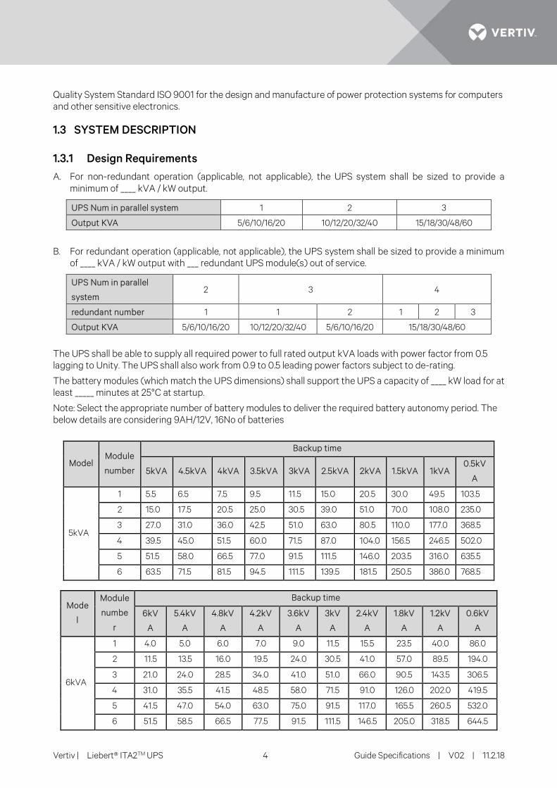
A. For non-redundant operation (applicable, not applicable), the UPS system shall be sized to provide a minimum of ____ kVA / kW output.
UPS Num in parallel system 1 2 3
Output KVA 5/6/10/16/20 10/12/20/32/40 15/18/30/48/60
B. For redundant operation (applicable, not applicable), the UPS system shall be sized to provide a minimum of ____ kVA / kW output with ___ redundant UPS module(s) out of service.
UPS Num in parallel
system 2 3 4
redundant number 1 1 2 1 2 3
Output KVA 5/6/10/16/20 10/12/20/32/40 5/6/10/16/20 15/18/30/48/60
The UPS shall be able to supply all required power to full rated output kVA loads with power factor from 0.5 lagging to Unity. The UPS shall also work from 0.9 to 0.5 leading power factors subject to de-rating.
The battery modules (which match the UPS dimensions) shall support the UPS a capacity of ____ kW load for at least _____ minutes at 25°C at startup.
Note: Select the appropriate number of battery modules to deliver the required battery autonomy period. The below details are considering 9AH/12V, 16No of batteries
Model Module
number
Backup time
5kVA 4.5kVA 4kVA 3.5kVA 3kVA 2.5kVA 2kVA 1.5kVA 1kVA 0.5kV
A
5kVA
1 5.5 6.5 7.5 9.5 11.5 15.0 20.5 30.0 49.5 103.5
2 15.0 17.5 20.5 25.0 30.5 39.0 51.0 70.0 108.0 235.0
3 27.0 31.0 36.0 42.5 51.0 63.0 80.5 110.0 177.0 368.5
4 39.5 45.0 51.5 60.0 71.5 87.0 104.0 156.5 246.5 502.0
5 51.5 58.0 66.5 77.0 91.5 111.5 146.0 203.5 316.0 635.5
6 63.5 71.5 81.5 94.5 111.5 139.5 181.5 250.5 386.0 768.5
Mode
l
Module
numbe
r
Backup time
6kV
A
5.4kV
A
4.8kV
A
4.2kV
A
3.6kV
A
3kV
A
2.4kV
A
1.8kV
A
1.2kV
A
0.6kV
A
6kVA
1 4.0 5.0 6.0 7.0 9.0 11.5 15.5 23.5 40.0 86.0
2 11.5 13.5 16.0 19.5 24.0 30.5 41.0 57.0 89.5 194.0
3 21.0 24.0 28.5 34.0 41.0 51.0 66.0 90.5 143.5 306.5
4 31.0 35.5 41.5 48.5 58.0 71.5 91.0 126.0 202.0 419.5
5 41.5 47.0 54.0 63.0 75.0 91.5 117.0 165.5 260.5 532.0
6 51.5 58.5 66.5 77.5 91.5 111.5 146.5 205.0 318.5 644.5
Vertiv | Liebert® ITA2TM UPS 5 Guide Specifications | V02 | 11.2.18
Model
Module
number
Backup time
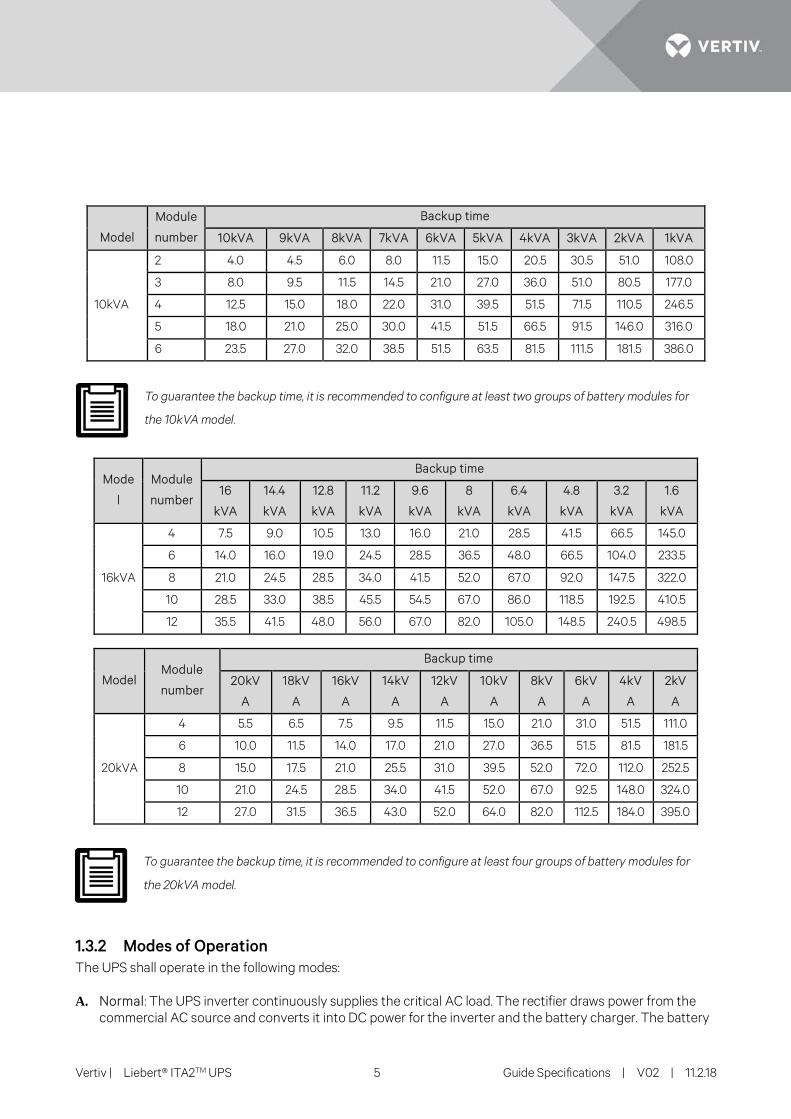
10kVA 9kVA 8kVA 7kVA 6kVA 5kVA 4kVA 3kVA 2kVA 1kVA
10kVA
2 4.0 4.5 6.0 8.0 11.5 15.0 20.5 30.5 51.0 108.0
3 8.0 9.5 11.5 14.5 21.0 27.0 36.0 51.0 80.5 177.0
4 12.5 15.0 18.0 22.0 31.0 39.5 51.5 71.5 110.5 246.5
5 18.0 21.0 25.0 30.0 41.5 51.5 66.5 91.5 146.0 316.0
6 23.5 27.0 32.0 38.5 51.5 63.5 81.5 111.5 181.5 386.0
To guarantee the backup time, it is recommended to configure at least two groups of battery modules for
the 10kVA model.
Mode
l
Module
number
Backup time
16
kVA
14.4
kVA
12.8
kVA
11.2
kVA
9.6
kVA
8
kVA
6.4
kVA
4.8
kVA
3.2
kVA
1.6
kVA
16kVA
4 7.5 9.0 10.5 13.0 16.0 21.0 28.5 41.5 66.5 145.0
6 14.0 16.0 19.0 24.5 28.5 36.5 48.0 66.5 104.0 233.5
8 21.0 24.5 28.5 34.0 41.5 52.0 67.0 92.0 147.5 322.0
10 28.5 33.0 38.5 45.5 54.5 67.0 86.0 118.5 192.5 410.5
12 35.5 41.5 48.0 56.0 67.0 82.0 105.0 148.5 240.5 498.5
Model Module
number
Backup time
20kV
A
18kV
A
16kV
A
14kV
A
12kV
A
10kV
A
8kV
A
6kV
A
4kV
A
2kV
A
20kVA
4 5.5 6.5 7.5 9.5 11.5 15.0 21.0 31.0 51.5 111.0
6 10.0 11.5 14.0 17.0 21.0 27.0 36.5 51.5 81.5 181.5
8 15.0 17.5 21.0 25.5 31.0 39.5 52.0 72.0 112.0 252.5
10 21.0 24.5 28.5 34.0 41.5 52.0 67.0 92.5 148.0 324.0
12 27.0 31.5 36.5 43.0 52.0 64.0 82.0 112.5 184.0 395.0
To guarantee the backup time, it is recommended to configure at least four groups of battery modules for
the 20kVA model.
1.3.2 Modes of Operation The UPS shall operate in the following modes:
A. Normal: The UPS inverter continuously supplies the critical AC load. The rectifier draws power from the commercial AC source and converts it into DC power for the inverter and the battery charger. The battery
Vertiv | Liebert® ITA2TM UPS 6 Guide Specifications | V02 | 11.2.18
charger maintains the battery in a fully charged and optimum operational condition. The inverter converts the DC power into clean and regulated AC power which is supplied to the critical load (conditioned line).
B. ECO Mode: The critical AC load shall be continuously powered by the bypass with the inverter available to power the load if the bypass source voltage or frequency exceeds adjustable parameters of power quality.
C. Battery: Upon failure or degradation of the primary AC source, the load will be supplied through the inverter drawing power from the battery. Visible and audible signals will alert the user during this operating state. The remaining autonomy time will be calculated by a diagnostic algorithm. Once the end of discharge (EoD) voltage is reached, the UPS will automatically disconnect the battery (internal or external) without the need for external devices.
Recharge: If the primary AC source returns within tolerance limits prior to a UPS automatic end of discharge shutdown, the rectifier will recommence powering the inverter and simultaneously recharging the battery through the battery converter. When the inverter has synchronized with the bypass, the UPS will recommence operating in double conversion mode without any break (0 ms) in the supply to the load.
If the primary AC source does not return within tolerance limits and the UPS performs an automatic end of discharge shutdown, the UPS will recommence operating in bypass mode until it is manually transferred to the inverter. Alternatively, it can be set to start in static bypass mode and automatically transfer to double conversion mode after a time delay, from the moment the rectifier start is complete and the bypass source is back within the synchronization windows. The time delay is selectable between 1 and 999 seconds (default: 10 seconds). During the selected delay, the UPS will charge the battery and phase-lock the inverter with bypass. If the inverter is unable to phase-lock the bypass at the end of the selected window, the load will remain fed by the bypass and the user will be prompted to confirm or cancel an interrupted transfer.
D. Bypass: If the UPS must be taken out of service, the static transfer switch shall transfer the load to the bypass source. The transfer process shall cause no interruption in power to the critical load. An optional external wrap-around maintenance bypass shall be used to ensure full isolation of the unit for the service of internal components while providing safety from arc flash.
E. Off-Battery: If the battery only is taken out of service, it shall be disconnected from the DC-DC converter by means of an external disconnect circuit breaker. The UPS shall continue to function and meet all of the specified steady-state performance criteria, except for the power outage backup time capability. If multiple battery strings are used, each string shall be capable of being electrically isolated for safety during maintenance.
F. Parallel: Inherent scalability features should be available to meet higher capacity and higher reliability requirements. Under normal operating conditions, the power delivered to the load will be equally shared between number of UPS units connected to the parallel bus with a tolerance of 5%. In the event of a unit failure or overload, the system will transfer to the bypass source.
G. Common Battery (for external battery bank): UPS should be able to support common battery function when multiple UPSs are connected in parallel. In this mode, each UPS can use the same battery to feed the required load.
1.3.3 Performance Requirements The solid-state power components, magnetic, electronic devices and over current protection devices shall operate within the manufacturer’s recommended temperature when the UPS is operating at 100% critical load and maintain battery charging under either of the following conditions:
• Any altitude within the specified operating range ≤3000m elevation. • Any ambient temperature within the specified operating range of 0°C to 50°C
1.3.4 Input A. Voltage: Input/output voltage specifications of the UPS shall be
• Rectifier AC Input: 220/230/240VAC, single-phase, two-wire-plus-ground for 5/6kVA 380/400/415VAC, three-phase, four-wire-plus-ground for 16/20KVA

Vertiv | Liebert® ITA2TM UPS 7 Guide Specifications | V02 | 11.2.18
Single-Phase or Three-phase supply for 10kVA
• Bypass AC Input : 220/230/240VAC, single-phase, two-wire-plus-ground for 5/6kVA 380/400/415VAC, three-phase, four-wire-plus-ground or Single Phase for 16/20KVA
Single-Phase or Three-phase supply for 10kVA
• AC Output: 220/230/240VAC, single-phase, two-wire-plus-ground for 5/6/10kVA 380/400/415VAC, three-phase, four-wire-plus-ground or Single-Phase for 16/20kVA
A. Voltage Range: 305-498VAC at full load; 173-498VAC at 50% derated load conditions without battery discharge
B. Frequency Range: 40 - 70Hz
C. Maximum Inrush Current: UPS inrush current not to exceed 1.5 times rated input current
D. Power Factor: Minimum 0.99 at full load & 0.98 at half load with nominal input voltage
Minimum 0.95 at full load for 3phase in/1 phase out for 10kVA
E. Current Distortion: Less than 5% THD at full load input current in double-conversion mode
F. Surge Protection: Sustains input surges of 4kV (Line to ground) without damage as per criteria listed in EN 61000-4-5: 1995
1.3.5 AC Output A. Load Rating: 100% of load rating for any load from 0.5 lagging to unity
B. Load power factor: Unity
C. Voltage Tolerance • ±1% RMS average for a balanced, three-phase load • ±2% for 100% unbalanced three phase load • +/- 3% for parallel UPS
D. Voltage Adjustment Range: ±5% for line drop compensation adjustable by factory service personnel
E. Voltage Distortion: • <2% for 0-100% linear loads
• <5% for 0-100% Non-linear loads
F. Frequency Regulation:
• Synchronized with internal clock: +/-0.25%
• Synchronized with bypass: +/-0.25%
G. Frequency synchronization window: Synchronized to bypass: Nominal ±5% Hz H. System Efficiency: defined as output kW/input kW at rated lagging load power factor; and not less than
the values listed below
In Online double conversion mode: (depending on load)
For 5/6kVA – up to 95.5%
For 10kVA- up to 95.8%
For 16/20kVA- up to 96.2%
In Eco mode: up to 99%
I. Phase Imbalance: • Balanced loads 120° ±1° • 100% unbalanced loads 120° ±1°
J. Voltage Transients (average of all three phases):
Vertiv | Liebert® ITA2TM UPS 8 Guide Specifications | V02 | 11.2.18
• 0-100% or 100-0% Response Meets IEC 62040-3: 2010 Figure 2 Curve 1, Class 1 Meets ITIC and CBEMA Curve Requirements
K. Overload Capacity:
105% - 125% of full load for 5minutes
125% - 150% of full load for 1minute
>150% of full load for a minimum of 200 milliseconds
1.3.6 Grounding
The UPS chassis shall have an equipment ground terminal.
1.4 ENVIRONMENTAL CONDITIONS
The UPS shall be able to withstand the following environmental conditions without damage or degradation of operating characteristics:
A. Operating Ambient Temperature
• UPS: 0 to 40 without de-rating and 40 to 50 with derating.
• Battery: 25°C ± 3°C (depends on battery mfg. recommendations)
B. Storage temperature
-40°C ~ +70°C (battery excluded); -25°C ~ +55°C (battery included) C. Relative Humidity
• 0 to 95%, non-condensing
D. Altitude • ≤ 3000m; above sea level derate power by 1% per each 100m increase
E. Audible Noise Level (measured 1m from the surface of the unit) • <55 dBA for 5/6/10kVA • <58 dBA for 16/20kVA
Vertiv | Liebert® ITA2TM UPS 9 Guide Specifications | V02 | 11.2.18
1.5 SUBMITTALS
1.5.1 Proposal Submittals Submittals with the proposal shall include:
• Descriptions of equipment to be furnished, including deviations from these specifications. • Document showing the efficiency certification by certified agency. • System configuration with single-line diagrams. • Detailed layouts of customer power and control connections. • Functional relationship of equipment, including weights, dimensions and heat dissipation. • Information to allow distribution system coordination. • Size and weight of shipping units to be handled by contractor.
1.5.2 Order Submittals Submittals supplied at time of order shall include:
• All of the documentation presented with the proposal, per Section 1.5.1 above. • Detailed installation drawings including all terminal locations. • Interconnect wiring diagrams showing conduit wiring with terminal numbers for each wire.
1.5.3 UPS Delivery Submittals Submittals upon UPS delivery shall include:
• A complete set of submittal drawings. • Two (2) sets of instruction manuals. Manuals shall include a functional description of the equipment,
safety precautions, instructions, step-by-step operating procedures and routine maintenance guidelines, including illustrations.
1.6 WARRANTY
1.6.1 UPS Warranty The UPS manufacturer shall warrant the unit against defects in workmanship and materials for 12 months after initial startup or 18 months after the shipping date, whichever comes first.
1.6.2 Warranty – End User Warranties associated with items not manufactured by the UPS supplier but included as part of the system shall be passed through to the end user.
Vertiv | Liebert® ITA2TM UPS 10 Guide Specifications | V02 | 11.2.18
1.7 QUALITY ASSURANCE
1.7.1 Manufacturer’s Qualifications A minimum of 20 years’ experience in the design, manufacture and testing of solid-state UPS systems shall be required.
The quality system for the engineering and manufacturing facility shall be certified to conform to Quality System Standard ISO 9001 for the design and manufacture of power protection systems for computers and other sensitive electronics
1.7.2 Factory Testing Before shipment, the manufacturer shall fully and completely test the UPS unit to ensure compliance with the specification.
The UPS unit shall be tested at the system-specified capacity. Testing shall be done using load banks at part-load and the full kW rating of the unit.
Operational discharge and recharge tests to ensure guaranteed rated performance.
System operations such as startup, shutdown and transfers shall be demonstrated.
A certified copy of the test results shall be available for each system as indicated on the order.
Vertiv | Liebert® ITA2TM UPS 11 Guide Specifications | V02 | 11.2.18
2. PRODUCT
2.1 FABRICATION
2.1.1 Materials
All materials of the UPS shall be new, of current manufacture, high grade and shall not have been in prior service except as required during factory testing. All active electronic devices shall be solid-state. All power semiconductors shall be sealed. Control logic and fuses shall be physically isolated from power train components to ensure operator safety and protection from heat.
2.1.2 UPS Internal Wiring Wiring practices, materials and coding shall be in accordance with the requirements of the National Electrical Code and applicable local codes and standards. All bolted connections of bus bars, lugs and cables shall be in accordance with requirements of the National Electric Code and other applicable standards. All electrical power connections shall be torqued to the required value and marked with a visual indicator
2.1.3 Field Wiring All field wiring power connections shall be to tin-plated copper bus bars for connection integrity. Bus bars shall have adequate space to allow two-hole, long-barrel, compression type lugs forming a permanent connection between field wiring and field-installed lugs.
Provisions shall be made in the cabinets to permit installation of input, output and external control cabling using raceway or conduit. Provision shall be made for top and bottom access to input, output, bypass and DC connections. In conformance with the NEC, connection cabinets shall provide for adequate wire bend radius.
2.1.4 Construction and Mounting The UPS shall be housed in an IP20 enclosure, designed for floor and rack mounting. The UPS shall be structurally adequate and have provisions for forklift handling. Maximum cabinet height shall be less than 0.5 meters for all UPS range.
2.1.5 Cooling Forced air cooling shall be provided to ensure that all components are operated well within temperature ratings. Airflow shall be controlled according to load demand. If one of the cooling fans experiences a fault, the UPS shall be immediately notified of the condition via the user interface and through remote monitoring services. The cooling air entry shall be from the front and air exit shall be at the back of the unit.
2.2 Equipment
2.2.1 UPS System The UPS system shall consist of an IGBT power factor-corrected rectifier, DC-DC converter and three-phase, transformer-free T-type inverter, bypass static transfer switch, bypass synchronizing circuitry, protective devices and accessories as specified. The specified system shall also include a battery disconnect breaker and battery system.
2.2.2 Surge Protection The UPS shall have built-in protection against surges, sags and over current from the AC source. The protection shall meet the requirements of IEC/EN 61000-4-5 including:
Vertiv | Liebert® ITA2TM UPS 12 Guide Specifications | V02 | 11.2.18
Level 4 (4kV) (Line to Earth), Level 3 (2kV) (Line to Line) Based on B
2.2.3 Output Protection The UPS shall be protected against sudden changes in output load and short circuits at the output terminals. The UPS shall have built-in protection against permanent damage to itself and the connected load for all predictable types of malfunctions. Fast-acting, current-limiting devices shall be used to protect against cascading failure of solid-state devices. Internal UPS malfunctions shall cause the module to trip off-line with minimum damage to the module and provide maximum information to maintenance personnel regarding the reason for tripping off-line. The load shall be automatically transferred to the bypass line uninterrupted for an internal UPS malfunction. The status of protective devices shall be indicated on a graphic display screen on the front of the unit.
2.3 Components
2.3.1 Rectifier The term rectifier shall denote the solid-state equipment and controls necessary to convert alternating current to regulated direct current to supply the inverter and charge the battery. The DC output of the rectifier shall meet the input requirements of the inverter without the battery being connected.
A. Input Current Harmonic Distortion The rectifier shall actively control and reduce input current distortion over the full operating range of the UPS without the need for an additional passive input filter. Input current THD shall be less than 5% (for 3 phase input/3 phase output & 1 phase input/1 phase output) at rated load and nominal voltage in double-conversion mode.
B. Dynamic Current Input Limit Reduction
The rectifier, in conjunction with the other UPS controls and circuitry, shall adjust the current demanded for battery charging as a function of UPS wattage load and input voltage level.
2.3.2 DC-DC Converter The term DC-DC converter shall denote the equipment and controls to regulate the output of the rectifier to the levels appropriate for charging the battery and to boost the battery voltage to the level required to operate the inverter. The DC-DC converter shall be solid-state, capable of providing rated output power and, for increased performance, shall be a pulse width-modulated design and shall utilize insulated gate bipolar transistors (IGBTs). The DC-DC converter shall control charging of the battery. The AC ripple voltage of the charger during float charging mode shall not exceed 3% RMS of the float voltage.
A. Battery Recharge
In addition to supplying power for the load, the rectifier/charger shall be capable of supplying a minimum of 5% of the module full load power rating for recharging the battery. The battery recharge rate capability shall be sufficient to replace 95% of the battery discharge power within ten (10) times the discharge time while running at 95% of full load at nominal voltage, provided that the battery can accept recharge at that rate. After the battery is recharged, the rectifier/charger shall maintain the battery at full charge until the next emergency operation.
B. Battery Equalize Charge
A manually initiated equalize charge feature shall be provided to apply an equalize voltage to the battery. A method shall be available to deactivate this feature for valve regulated battery systems.
C. Stop Battery Charging Function
Battery charging/discharging shall be suspended when over temperature is sensed in the battery cabinet or when environmental contact is closed.
D. Overvoltage Protection
Vertiv | Liebert® ITA2TM UPS 13 Guide Specifications | V02 | 11.2.18
There shall be DC overvoltage protection so that if the DC voltage rises to the pre-set limit, the microprocessor will automatically switch off the battery charger and initiate an uninterrupted load transfer to the static bypass line.
E. Temperature-Compensated Charging The UPS shall adjust the battery charging voltage based on the battery temperature reported from external battery temperature sensors. Excessive difference in the temperature measurements shall be reported and the charging voltage adjusted to protect the batteries from excessive current.
F. Battery Load Testing
The UPS shall be capable of performing battery load testing under operator supervision. To accomplish this, the rectifier shall reduce charging voltage to force the batteries to carry the load for a short time. If the curve of battery voltage drop indicates diminished battery capacity, the UPS shall display an alarm message. If the voltage drop indicates battery failure, the UPS shall annunciate the appropriate alarms.
2.3.3 Inverter The term inverter shall denote the equipment and controls to convert direct current from the rectifier or battery via the DC-DC converter to precise alternating current to power the load. The inverter shall be solid-state, capable of providing rated output power and, for increased performance; the inverter shall be a pulse-width-modulated design and shall utilize insulated gate bipolar transistors (IGBTs). To further enhance reliable performance and efficiency, the inverter shall not require an inverter output series static switch/isolator for the purposes of overload or fault isolation or transfers to bypass.
A. Voltage regulation
The advanced vector control algorithm enables the real-time control of the individual phases with consequent improvement of transient responses, short circuit behavior and synchronism between UPS output and bypass supply in the case of distorted mains voltage.
B. Overload Capability
The inverter shall be capable of supplying an overload current as specified in section 1.3.5. For greater currents or longer time duration, to prevent damage to components, the inverter will be self-protecting by means of electronic current-limitation.
The control logic shall disconnect the inverter from AC load without the need to clear protective devices and the critical load shall be transferred to the static bypass supply automatically.
C. Output Frequency
The inverter shall track the bypass continuously, providing the bypass source maintains a frequency of 50Hz ±0.25%.
D. Phase-to-Phase Balance
The inverter shall provide a phase-to-phase voltage displacement of no worse than ±1˚ with a 100% unbalanced load.
E. Inverter Fault Sensing and Isolation
The UPS shall be provided with a means to detect a malfunctioning inverter and isolate it from the critical load bus to prevent disturbance of the critical load voltage beyond the specified limits.
F. Battery Protection
The inverter shall be provided with monitoring and control circuits to protect the battery system from damage due to excessive discharge. Inverter shutdown shall be initiated when the battery voltage has reached the end of discharge voltage. The battery end-of-discharge voltage shall be calculated and automatically adjusted for partial load conditions to allow extended operation without damaging the battery. Automatic shutdown based on discharge time shall not be acceptable.
Vertiv | Liebert® ITA2TM UPS 14 Guide Specifications | V02 | 11.2.18
2.3.4 Inverter Bypass Operation When maintenance is required or when the inverter cannot maintain voltage to the load due to sustained overload or malfunction, a bypass circuit shall be provided to isolate the inverter output from the load and provide a path for power directly from an alternate AC (bypass) source. The UPS control system shall constantly monitor the availability of the inverter bypass circuit to perform a transfer. The inverter bypass circuit shall consist of a continuous duty bypass static switch to isolate the static bypass switch from the bypass utility source. The bypass static switch shall denote the solid-state device incorporating SCRs (silicon controlled rectifiers) that can automatically and instantaneously connect the alternate AC source to the load.
A. Static Bypass Switch Rating
The static bypass switch shall be rated for continuous duty operation at full rated load for highest reliability.
B. Manual Load Transfers
A manual load transfer between the inverter output and the alternate AC source shall be initiated from the control panel. Manually initiated transfers shall be make-before-break, utilizing the inverter and the bypass static switch.
C. Automatic Load Transfers
An automatic load transfer between the inverter output and the alternate AC source shall be initiated if an overload condition is sustained for a period in excess of the inverter output capability or due to a malfunction that would affect the output voltage. Transfers caused by overloads shall initiate an automatic retransfer of the load to the inverter only after the load has returned to a level within the rating of the inverter source and the alarm has been acknowledged.
D. Momentary Overloads
In the event of a load current inrush or branch load circuit fault in excess of the inverter rating, the bypass static switch shall connect the alternate AC source to the load for at least 200 milliseconds, allowing >150% of the normal rated output current to flow. Output voltage shall be sustained to the extent the alternate AC source capacity permits. If the overload condition is removed before the end of the 200-millisecond period, the bypass static switch shall turn off and the load shall remain on inverter power. If the overload remains, then a transfer to the alternate AC source is to be completed.
E. Back-Feed Protection
In the event of back feeding during battery mode, UPS shall be turned off. And UPS should comply with all UL/TUV safety standards.
F. Active ECO-Mode (Applicable for single UPS only)
When selected, this mode of operation shall transfer the load to the bypass source and maintain it there as long as the bypass source frequency, slew rate and voltage are within the adjusted operating parameters. While in this mode, the inverter shall remain operating to demonstrate the ability to instantaneously assume the load without interrupting the output voltage. Should the bypass source go outside the adjusted limits, the bypass static switch shall turn off, isolating the load from the bypass while the inverter assumes the full critical load. The load shall be transferred from the bypass source to the inverter while maintaining the output voltage within the ITIC and CBEMA curves.
2.3.5 Display and Controls A. UPS Control Panel
The operator control and display panel shall be located on the front of the UPS. The control panel includes a min 320 x 240-pixel multi-lingual, graphic liquid crystal display, allowing the user to operate and control the UPS checking parameters, as well as UPS and battery status and retrieve up to 2000 events/alarm logs for reference and diagnosis. Complete access to all LCD menu is possible through four software- assigned buttons shall be located below the display. LCD shall be auto rotate to vertical or horizontal mode thus no adjustment to the LCD mounting need to be carried depending on Tower or Rack installation
B. Logic
Vertiv | Liebert® ITA2TM UPS 15 Guide Specifications | V02 | 11.2.18
UPS system logic and control programming shall reside in a microprocessor-based control system with nonvolatile flash memory. Rectifier, inverter and system control logic shall utilize high-speed digital signal processors (DSPs). SCI bus shall be used to communicate between the logic and the User Interface as well as the options. Switches, contacts and relays shall be used only to signal the logic system as to the status of mechanical devices or to signal user control inputs. Customer external signals shall be isolated from the UPS logic by relays or optical isolation.
C. Metered Values
The LCD displays the system real-time running data. The following parameters should be displayed on the LCD. All the displayed values are effective value and should be refreshed less than 10s and the accuracy of the displayed voltage effective value is at least ±2%.
• Input: voltage (L-N) & (L-L), frequency, power factor, and energy (kWh)
• Battery: battery status, battery voltage, battery current, battery backup time, remaining capacity
• Bypass: bypass voltage, frequency
• Output: kVA, KW, load PF, load percent
• Efficiency curve
D. Power Flow Indications
A power flow diagram shall graphically depict whether the load is being supplied from the inverter, bypass or battery and shall provide, on the same screen.
Main Display Screen The following UPS status messages shall be displayed:
• Rectifier (Off / Main Input On / Battery Input On)• Input Supply (Normal Mode / Battery Mode / All Off)• Battery Self Test (True / False) • EPO (True / False) • Charger (On / Off)• Inverter (Off / Soft Start / On)• Bypass (Normal / Abnormal)• Output Supply (All Off / Bypass Mode / Inverter Mode / Output Disable)• Inverter On (Enable / Disable)
E. HMI Control Buttons
Buttons shall be provided to start and stop the inverter. A pop-up message requesting confirmation shall be displayed whenever a command is initiated that would change the status of the UPS.
Other buttons shall be provided for the navigation.
F. Event Log
This menu item shall display the list of events that have occurred recently while the UPS was in operation. The Event Log shall store up to 2000 events, with the oldest events being overwritten first if the log’s capacity is reached.
G. Alarms
The following alarm messages shall be displayed: • Input abnormal• Input phase reversed • Rectifier fault• Charger Fault
Vertiv | Liebert® ITA2TM UPS 16 Guide Specifications | V02 | 11.2.18
• Battery Reversed • No Battery • Fan fault • Parallel Comm. Fail • Bypass Abnormal • Control Power Fail • Unit Over Load • System Over Load • Bypass Phase Reversed • Load Sharing Fault • Bypass over Current.
H. Controls
System-level control functions shall be accessed via control display screen: • Turn on/off/to bypass • Mute/unmute audible alarms • Start/stop manual battery test • Clear faults
2.3.6 Self-Diagnostics • Event Log File - The control system shall maintain a log of the event conditions that have occurred
during system operation. Each log shall contain the event name, event time/date stamp.
2.3.7 Remote Monitoring and Integration Capabilities A. Communication Cards:
The UPS can be equipped with following communication card(s) including: • Built-in RJ 45 port for webpage • Built-in Multi-function port that can be configured as Modbus or to connect to environmental sensors • Optional Communication card- shall provide Web access, environmental sensor data, and third-party
customer protocols for the UPS and manage a wide range of operating parameters, sending data over ethernet networks via secure HTTPS protocol and alarms and notifications via SNMP traps. It also shall be capable to integrate with any existing building management system. And compatible with shutdown software (used for safe shutdown of severs in the event of battery drained).
• Optional Software- shall be provided to support the monitoring of multiple no of UPS systems at single platform.
B. Output Alarm Contacts:
At least two programmable output dry contacts should be available in order to notify the UPS status such as Low battery, UPS fail, on battery, on bypass etc.
C. Customer Input Contacts:
At least two programmable input dry contacts should be available to activate battery mode shutdown or any mode shutdown or maintenance mode.
D. EPO port: The EPO port shall be provided to switch off the UPS in emergency conditions. The system will turn off the rectifier, inverter and stop powering the load immediately (inverter and bypass output included), and the battery stops charging or discharging.
2.3.8 Battery Plant The battery plant shall comply with the following specifications
Each battery modules are designed to match the UPS cabinet. It should also support tower and rack mount installations. Each battery module contains 9AH/12V VRLA SMF batteries, 16nos. So, the number battery
Vertiv | Liebert® ITA2TM UPS 17 Guide Specifications | V02 | 11.2.18
modules shall be chosen according to the specified battery autonomy period. Each battery module should be equipped with output switch for disconnection when maintenance needed and communication port to communicate status with UPS system. Accessories required to connect to UPS system shall be consider under the scope of supply.
VRLA SMF Battery specification:-
Batteries shall be suitable for high efficient discharge applications. It supports at least for more than 260cycles at 100% discharge in cycle service up to 5years in standby service. Batteries & its internal material should also comply with the latest UL standards.
2.3.9 Optional Accessories and Features A. Load Bus Sync
The Load Bus Sync (LBS) shall enable two independent single-module UPS units to stay in sync when operating on battery or unsynchronized input sources. The LBS shall determine the master and slave relationship between UPS units. The LBS shall be installed within each single-module UPS.
B. Communication Card
A communication card shall provide Web-based UPS monitoring and management capabilities and deliver one or two remote monitoring protocols including SNMP (v1, v2, and v3) and Modbus.
C. Power Distribution Cabinet (POD)
POD shall be provided additionally to enable safe and reliable power distribution function.
Vertiv | Liebert® ITA2TM UPS 18 Guide Specifications | V02 | 11.2.18
3. EXECUTION
3.1 FIELD QUALITY CONTROL
The following inspections and test procedures shall be performed by factory-trained field service personnel during the UPS startup.
A. Visual Inspection • Inspect equipment for signs of damage. • Verify installation per drawings supplied with installation manuals or submittal package. • Inspect cabinets for foreign objects. • Verify that neutral and ground conductors are properly sized and configured per supplier’s
requirements as noted in suppliers drawings supplied with installation manuals or submittal package. • Inspect each battery jar for proper polarity. • Verify that all printed circuit boards are configured properly.
B. Mechanical Inspection • Check all control wiring connections for tightness. • Check all power wiring connections for tightness. • Check all terminal screws, nuts and/or spade lugs for tightness.
C. Electrical Inspection • Check all fuses for continuity. • Confirm input and bypass voltage and phase rotation are correct. • Verify control transformer connections are correct for voltages being used. • Ensure connection and voltage of the battery string(s).
3.2 UNIT STARTUP
1. Energize control power. 2. Perform control/logic checks and adjust to meet specification. 3. Verify DC float and equalize voltage levels. 4. Verify DC voltage clamp and overvoltage shutdown levels. 5. Verify battery discharge, low battery warning and low battery shutdown levels. 6. Verify fuse monitor alarms and system shutdown. 7. Verify inverter voltages and regulation circuits. 8. Verify inverter/bypass sync circuits and set overlap time. 9. Perform manual transfers and returns. 10. Simulate utility outage at no load. 11. Verify proper recharge.
Vertiv | Liebert® ITA2TM UPS 19 Guide Specifications | V02 | 11.2.18
3.3 MANUFACTURER’S FIELD SERVICE
A. Service Personnel
The UPS manufacturer shall directly employ a nationwide service organization, consisting of factory-trained field service personnel dedicated to the startup and maintenance of UPS and power equipment.
The manufacturer shall provide a national dispatch center to coordinate field service personnel schedules. One toll-free number shall reach a qualified support person 24 hours a day, 7 days a week and 365 days a year. If emergency service is required, on-site response time shall be 4 hours or less within 150 miles of a supplier’s service center.
Two local customer engineers shall be assigned to the site with a regional office as a backup. Escalation procedures shall be in place to notify Power Technical Support if a site is not functioning within 24 hours.
B. Replacement Parts Stocking
Parts shall be available through an extensive network to ensure round-the-clock parts availability throughout the country.
Spare parts shall be stocked by local field service personnel with backup available from national parts centers and the manufacturing location. A Customer Support Parts Coordinator shall be on call 24 hours a day, 7 days a week, and 365 days a year for immediate parts availability.
C. Maintenance Contracts
A complete offering of preventive and full-service maintenance contracts for both the UPS system and battery system shall be available.
Vertiv | Liebert® ITA2TM UPS 20 Guide Specifications | V02 | 11.2.18
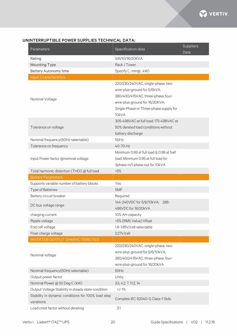
UNINTERRUPTIBLE POWER SUPPLIES TECHNICAL DATA:
Parameters Specification data Suppliers
Data
Rating 5/6/10/16/20KVA
Mounting Type Rack / Tower
Battery Autonomy time Specify (…[email protected])
Input Characteristics
Nominal Voltage
220/230/240VAC, single-phase, two-
wire-plus-ground for 5/6kVA;
380/400/415VAC, three-phase, four-
wire-plus-ground for 16/20KVA;
Single-Phase or Three-phase supply for
10kVA
Tolerance on voltage
305-498VAC at full load; 173-498VAC at
50% derated load conditions without
battery discharge
Nominal frequency(60Hz selectable) 50Hz
Tolerance on frequency 40-70 Hz
Input Power factor @nominal voltage
Minimum 0.99 at full load & 0.98 at half
load ;Minimum 0.95 at full load for
3phase in/1 phase out for 10kVA
Total harmonic distortion (THDi) @ full load <5%
Battery Parameters
Supports variable number of battery blocks Yes
Type of Batteries SMF
Battery circuit breaker Required
DC bus voltage range 144-240VDC for 5/6/10kVA; 288-
488VDC for 16/20kVA
charging current 10% AH capacity
Ripple voltage <5% (RMS Value) Vfloat
End cell voltage 1.6-1.85V/cell selectable
Float charge voltage 2.27V/cell
INVERTER OUTPUT CHARACTERISTICS
Nominal voltage
220/230/240VAC, single-phase, two-
wire-plus-ground for 5/6/10kVA;
380/400/415VAC, three-phase, four-
wire-plus-ground for 16/20kVA
Nominal frequency(60Hz selectable) 50Hz
Output power factor Unity
Nominal Power @ 50 Deg C (kW) 3.5, 4.2, 7, 11.2, 14
Output Voltage Stability in steady state condition +/-1%
Stability in dynamic conditions for 100% load step
variations Complies IEC 62040-3, Class-1 Stds.
Load crest factor without derating 3:1
Vertiv | Liebert® ITA2TM UPS 21 Guide Specifications | V02 | 11.2.18
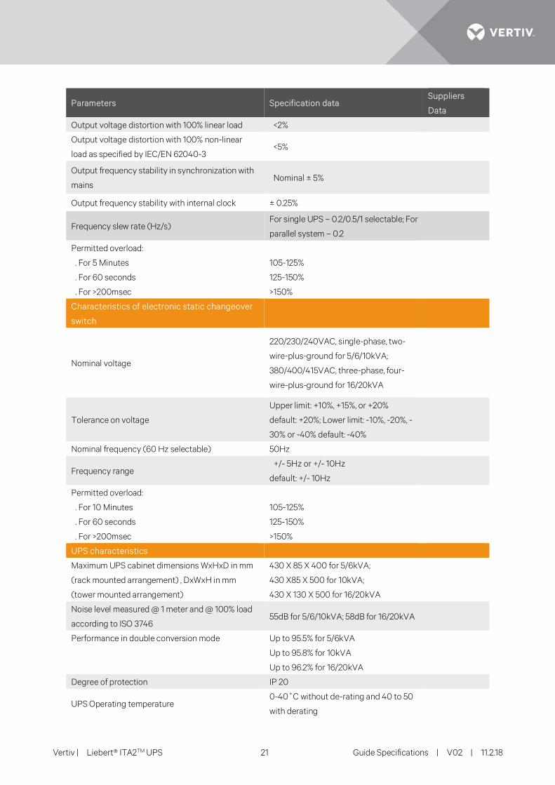
Parameters Specification data Suppliers
Data
Output voltage distortion with 100% linear load <2%
Output voltage distortion with 100% non-linear
load as specified by IEC/EN 62040-3 <5%
Output frequency stability in synchronization with
mains Nominal ± 5%
Output frequency stability with internal clock ± 0.25%
Frequency slew rate (Hz/s) For single UPS – 0.2/0.5/1 selectable; For
parallel system – 0.2
Permitted overload:
. For 5 Minutes 105-125%
. For 60 seconds 125-150%
. For >200msec >150%
Characteristics of electronic static changeover
switch
Nominal voltage
220/230/240VAC, single-phase, two-
wire-plus-ground for 5/6/10kVA;
380/400/415VAC, three-phase, four-
wire-plus-ground for 16/20kVA
Tolerance on voltage
Upper limit: +10%, +15%, or +20%
default: +20%; Lower limit: -10%, -20%, -
30% or -40% default: -40%
Nominal frequency (60 Hz selectable) 50Hz
Frequency range +/- 5Hz or +/- 10Hz
default: +/- 10Hz
Permitted overload:
. For 10 Minutes 105-125%
. For 60 seconds 125-150%
. For >200msec >150%
UPS characteristics
Maximum UPS cabinet dimensions WxHxD in mm
(rack mounted arrangement) , DxWxH in mm
(tower mounted arrangement)
430 X 85 X 400 for 5/6kVA;
430 X85 X 500 for 10kVA;
430 X 130 X 500 for 16/20kVA
Noise level measured @ 1 meter and @ 100% load
according to ISO 3746 55dB for 5/6/10kVA; 58dB for 16/20kVA
Performance in double conversion mode Up to 95.5% for 5/6kVA
Up to 95.8% for 10kVA
Up to 96.2% for 16/20kVA
Degree of protection IP 20
UPS Operating temperature 0-40˚C without de-rating and 40 to 50
with derating
Vertiv | Liebert® ITA2TM UPS 22 Guide Specifications | V02 | 11.2.18
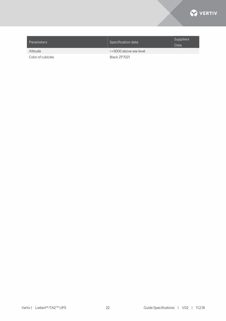
Parameters Specification data Suppliers
Data
Altitude <=3000 above sea level
Color of cubicles Black ZP7021