Embed Size (px)
Citation preview
AC PowerFor Business-Critical Continuity™
Liebert® PPC™ Precision Power CenterUser Manual - Three Phase, 300, 450 & 800kVA; 60 Hz

i
TABLE OF CONTENTS
IMPORTANT SAFETY INSTRUCTIONS . . . . . . . . . . . . . . . . . . . . . . . . . . . . . . . . . . . . . . . . . . . . . . . .1
SAVE THESE INSTRUCTIONS . . . . . . . . . . . . . . . . . . . . . . . . . . . . . . . . . . . . . . . . . . . . . . . . .1
1.0 INSTALLATION INSTRUCTIONS . . . . . . . . . . . . . . . . . . . . . . . . . . . . . . . . . . . . . . . . . . . . . . .2
1.1 Unpacking and Installation . . . . . . . . . . . . . . . . . . . . . . . . . . . . . . . . . . . . . . . . . . . . . . . . . . . . 21.1.1 Unpacking and Preliminary Inspection . . . . . . . . . . . . . . . . . . . . . . . . . . . . . . . . . . . . . . . . . . . 21.1.2 Handling Considerations . . . . . . . . . . . . . . . . . . . . . . . . . . . . . . . . . . . . . . . . . . . . . . . . . . . . . . . 21.1.3 Unit Preparation. . . . . . . . . . . . . . . . . . . . . . . . . . . . . . . . . . . . . . . . . . . . . . . . . . . . . . . . . . . . . . 31.1.4 Location Considerations. . . . . . . . . . . . . . . . . . . . . . . . . . . . . . . . . . . . . . . . . . . . . . . . . . . . . . . . 3
1.2 Power and Control Wiring . . . . . . . . . . . . . . . . . . . . . . . . . . . . . . . . . . . . . . . . . . . . . . . . . . . . . 71.2.1 Distribution Section Mounting and Wiring . . . . . . . . . . . . . . . . . . . . . . . . . . . . . . . . . . . . . . . . 71.2.2 Side-Section Electrical Connections . . . . . . . . . . . . . . . . . . . . . . . . . . . . . . . . . . . . . . . . . . . . . 101.2.3 Input Power Connections . . . . . . . . . . . . . . . . . . . . . . . . . . . . . . . . . . . . . . . . . . . . . . . . . . . . . . 111.2.4 System Grounding . . . . . . . . . . . . . . . . . . . . . . . . . . . . . . . . . . . . . . . . . . . . . . . . . . . . . . . . . . . 121.2.5 Grounding Electrode Conductor . . . . . . . . . . . . . . . . . . . . . . . . . . . . . . . . . . . . . . . . . . . . . . . . 121.2.6 Output Power Connections . . . . . . . . . . . . . . . . . . . . . . . . . . . . . . . . . . . . . . . . . . . . . . . . . . . . 131.2.7 Control Wiring Connections. . . . . . . . . . . . . . . . . . . . . . . . . . . . . . . . . . . . . . . . . . . . . . . . . . . . 14
2.0 INSPECTION AND STARTUP CHECKLIST . . . . . . . . . . . . . . . . . . . . . . . . . . . . . . . . . . . . . . .16
2.1 Internal Inspection Overview . . . . . . . . . . . . . . . . . . . . . . . . . . . . . . . . . . . . . . . . . . . . . . . . . 16
2.2 Internal Inspection Procedure . . . . . . . . . . . . . . . . . . . . . . . . . . . . . . . . . . . . . . . . . . . . . . . . . 16
2.3 Startup and Monitoring System Check Overview . . . . . . . . . . . . . . . . . . . . . . . . . . . . . . . . . 17
2.4 Startup Procedure . . . . . . . . . . . . . . . . . . . . . . . . . . . . . . . . . . . . . . . . . . . . . . . . . . . . . . . . . . 18
2.5 Monitoring System Check . . . . . . . . . . . . . . . . . . . . . . . . . . . . . . . . . . . . . . . . . . . . . . . . . . . . 19
2.6 Send Completed Checklist to Emerson Network Power . . . . . . . . . . . . . . . . . . . . . . . . . . . . 19
3.0 OPERATING INSTRUCTIONS . . . . . . . . . . . . . . . . . . . . . . . . . . . . . . . . . . . . . . . . . . . . . . . .20
3.1 Startup Procedures. . . . . . . . . . . . . . . . . . . . . . . . . . . . . . . . . . . . . . . . . . . . . . . . . . . . . . . . . . 203.1.1 Emergency Shutdown. . . . . . . . . . . . . . . . . . . . . . . . . . . . . . . . . . . . . . . . . . . . . . . . . . . . . . . . . 203.1.2 Normal System Shutdown . . . . . . . . . . . . . . . . . . . . . . . . . . . . . . . . . . . . . . . . . . . . . . . . . . . . . 203.1.3 Normal System Startup . . . . . . . . . . . . . . . . . . . . . . . . . . . . . . . . . . . . . . . . . . . . . . . . . . . . . . . 213.1.4 Manual Restart. . . . . . . . . . . . . . . . . . . . . . . . . . . . . . . . . . . . . . . . . . . . . . . . . . . . . . . . . . . . . . 21
3.2 Power Monitor Panel . . . . . . . . . . . . . . . . . . . . . . . . . . . . . . . . . . . . . . . . . . . . . . . . . . . . . . . . 22
4.0 MAINTENANCE . . . . . . . . . . . . . . . . . . . . . . . . . . . . . . . . . . . . . . . . . . . . . . . . . . . . . . . . .25
4.1 Corrective Maintenance (Repair) . . . . . . . . . . . . . . . . . . . . . . . . . . . . . . . . . . . . . . . . . . . . . . 25
4.2 Preventive Maintenance (Inspection & Cleaning) . . . . . . . . . . . . . . . . . . . . . . . . . . . . . . . . . 264.2.1 Inspection Schedule . . . . . . . . . . . . . . . . . . . . . . . . . . . . . . . . . . . . . . . . . . . . . . . . . . . . . . . . . . 26
ii
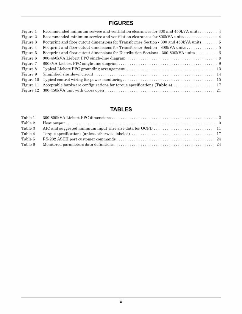
FIGURESFigure 1 Recommended minimum service and ventilation clearances for 300 and 450kVA units . . . . . . . . 4Figure 2 Recommended minimum service and ventilation clearances for 800kVA units . . . . . . . . . . . . . . . 4Figure 3 Footprint and floor cutout dimensions for Transformer Section - 300 and 450kVA units . . . . . . . 5Figure 4 Footprint and floor cutout dimensions for Transformer Section - 800kVA units . . . . . . . . . . . . . . 5Figure 5 Footprint and floor cutout dimensions for Distribution Sections - 300-800kVA units . . . . . . . . . . 6Figure 6 300-450kVA Liebert PPC single-line diagram . . . . . . . . . . . . . . . . . . . . . . . . . . . . . . . . . . . . . . . . . 8Figure 7 800kVA Liebert PPC single-line diagram . . . . . . . . . . . . . . . . . . . . . . . . . . . . . . . . . . . . . . . . . . . . . 9Figure 8 Typical Liebert PPC grounding arrangement . . . . . . . . . . . . . . . . . . . . . . . . . . . . . . . . . . . . . . . . . 13Figure 9 Simplified shutdown circuit . . . . . . . . . . . . . . . . . . . . . . . . . . . . . . . . . . . . . . . . . . . . . . . . . . . . . . . 14Figure 10 Typical control wiring for power monitoring . . . . . . . . . . . . . . . . . . . . . . . . . . . . . . . . . . . . . . . . . . 15Figure 11 Acceptable hardware configurations for torque specifications (Table 4) . . . . . . . . . . . . . . . . . . . 17Figure 12 300-450kVA unit with doors open . . . . . . . . . . . . . . . . . . . . . . . . . . . . . . . . . . . . . . . . . . . . . . . . . . 21
TABLESTable 1 300-800kVA Liebert PPC dimensions . . . . . . . . . . . . . . . . . . . . . . . . . . . . . . . . . . . . . . . . . . . . . . . . 2Table 2 Heat output . . . . . . . . . . . . . . . . . . . . . . . . . . . . . . . . . . . . . . . . . . . . . . . . . . . . . . . . . . . . . . . . . . . . . 3Table 3 AIC and suggested minimum input wire size data for OCPD . . . . . . . . . . . . . . . . . . . . . . . . . . . . 11Table 4 Torque specifications (unless otherwise labeled) . . . . . . . . . . . . . . . . . . . . . . . . . . . . . . . . . . . . . . 17Table 5 RS-232 ASCII port customer commands . . . . . . . . . . . . . . . . . . . . . . . . . . . . . . . . . . . . . . . . . . . . . 24Table 6 Monitored parameters data definitions . . . . . . . . . . . . . . . . . . . . . . . . . . . . . . . . . . . . . . . . . . . . . . 24
1
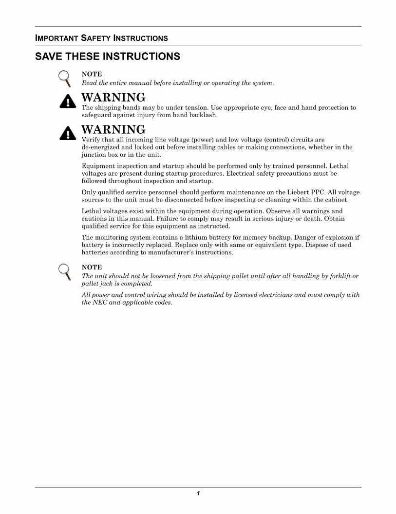
IMPORTANT SAFETY INSTRUCTIONS
SAVE THESE INSTRUCTIONS
NOTERead the entire manual before installing or operating the system.
! WARNINGThe shipping bands may be under tension. Use appropriate eye, face and hand protection to safeguard against injury from band backlash.
! WARNINGVerify that all incoming line voltage (power) and low voltage (control) circuits are de-energized and locked out before installing cables or making connections, whether in the junction box or in the unit.
Equipment inspection and startup should be performed only by trained personnel. Lethal voltages are present during startup procedures. Electrical safety precautions must be followed throughout inspection and startup.
Only qualified service personnel should perform maintenance on the Liebert PPC. All voltage sources to the unit must be disconnected before inspecting or cleaning within the cabinet.
Lethal voltages exist within the equipment during operation. Observe all warnings and cautions in this manual. Failure to comply may result in serious injury or death. Obtain qualified service for this equipment as instructed.
The monitoring system contains a lithium battery for memory backup. Danger of explosion if battery is incorrectly replaced. Replace only with same or equivalent type. Dispose of used batteries according to manufacturer’s instructions.
NOTEThe unit should not be loosened from the shipping pallet until after all handling by forklift or pallet jack is completed.
All power and control wiring should be installed by licensed electricians and must comply with the NEC and applicable codes.
Installation Instructions
2
1.0 INSTALLATION INSTRUCTIONS
1.1 Unpacking and Installation
1.1.1 Unpacking and Preliminary Inspection
A quality installation begins on the receiving dock.
1. Inspect the shipping crate(s) for damage or signs of mishandling before unpacking the unit(s). Check Shock-Watch indicator.
2. Open the shipping crates carefully. (Use care to avoid puncturing the container with sharp objects that would damage the contents.)
3. Remove the packing and vapor barriers and inspect the equipment for any obvious shipping damages.
If any damage as a result of shipping is observed, immediately file a damage claim with the shipping agency and forward a copy to:
Emerson Network Power1050 Dearborn DriveP.O. Box 29186Columbus, Ohio 43229 USA
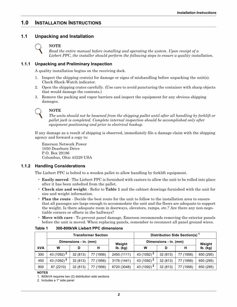
1.1.2 Handling Considerations
The Liebert PPC is bolted to a wooden pallet to allow handling by forklift equipment.
• Easily moved - The Liebert PPC is furnished with casters to allow the unit to be rolled into place after it has been unbolted from the pallet.
• Check size and weight - Refer to Table 1 and the cabinet drawings furnished with the unit for size and weight information.
• Plan the route - Decide the best route for the unit to follow to the installation area to ensure that all passages are large enough to accommodate the unit and the floors are adequate to support the weight. Is there adequate room in doorways, elevators, ramps, etc.? Are there any non-nego-tiable corners or offsets in the hallways?
• Move with care - To prevent panel damage, Emerson recommends removing the exterior panels before the unit is moved. When replacing panels, remember to reconnect all panel ground wires.
NOTERead the entire manual before installing and operating the system. Upon receipt of a Liebert PPC, the installer should perform the following steps to ensure a quality installation.
NOTEThe units should not be loosened from the shipping pallet until after all handling by forklift or pallet jack is completed. Complete internal inspection should be accomplished only after equipment positioning and prior to electrical hookup.
Table 1 300-800kVA Liebert PPC dimensions
kVA
Transformer Section Distribution Side Section(s) 1
Dimensions - in. (mm)Weightlb. (kg)
Dimensions - in. (mm)Weightlb. (kg)W D H W D H
300 43 (1092) 2 32 (813) 77 (1956) 2450 (1111) 43 (1092) 2 32 (813) 77 (1956) 650 (295)
450 43 (1092) 2 32 (813) 77 (1956) 3176 (1441) 43 (1092) 2 32 (813) 77 (1956) 650 (295)
800 87 (2210) 32 (813) 77 (1956) 6720 (3048) 43 (1092) 2 32 (813) 77 (1956) 650 (295)
NOTES1. 800kVA requires two (2) distribution side sections2. Includes a 1" side panel
Installation Instructions
3
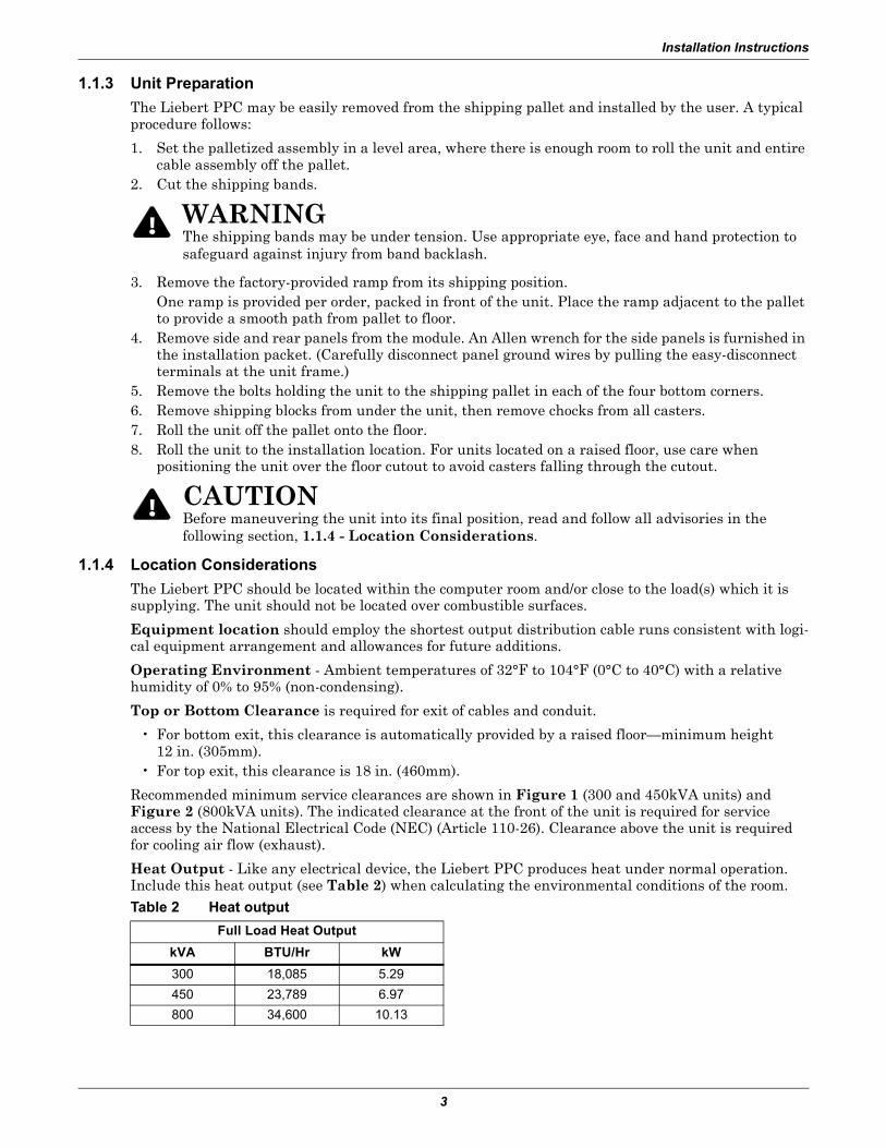
1.1.3 Unit Preparation
The Liebert PPC may be easily removed from the shipping pallet and installed by the user. A typical procedure follows:
1. Set the palletized assembly in a level area, where there is enough room to roll the unit and entire cable assembly off the pallet.
2. Cut the shipping bands.
3. Remove the factory-provided ramp from its shipping position. One ramp is provided per order, packed in front of the unit. Place the ramp adjacent to the pallet to provide a smooth path from pallet to floor.
4. Remove side and rear panels from the module. An Allen wrench for the side panels is furnished in the installation packet. (Carefully disconnect panel ground wires by pulling the easy-disconnect terminals at the unit frame.)
5. Remove the bolts holding the unit to the shipping pallet in each of the four bottom corners.6. Remove shipping blocks from under the unit, then remove chocks from all casters.7. Roll the unit off the pallet onto the floor.8. Roll the unit to the installation location. For units located on a raised floor, use care when
positioning the unit over the floor cutout to avoid casters falling through the cutout.
1.1.4 Location Considerations
The Liebert PPC should be located within the computer room and/or close to the load(s) which it is supplying. The unit should not be located over combustible surfaces.
Equipment location should employ the shortest output distribution cable runs consistent with logi-cal equipment arrangement and allowances for future additions.
Operating Environment - Ambient temperatures of 32°F to 104°F (0°C to 40°C) with a relative humidity of 0% to 95% (non-condensing).
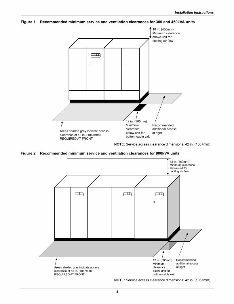
Top or Bottom Clearance is required for exit of cables and conduit.
• For bottom exit, this clearance is automatically provided by a raised floor—minimum height 12 in. (305mm).
• For top exit, this clearance is 18 in. (460mm).
Recommended minimum service clearances are shown in Figure 1 (300 and 450kVA units) and Figure 2 (800kVA units). The indicated clearance at the front of the unit is required for service access by the National Electrical Code (NEC) (Article 110-26). Clearance above the unit is required for cooling air flow (exhaust).
Heat Output - Like any electrical device, the Liebert PPC produces heat under normal operation. Include this heat output (see Table 2) when calculating the environmental conditions of the room.
! WARNINGThe shipping bands may be under tension. Use appropriate eye, face and hand protection to safeguard against injury from band backlash.
! CAUTIONBefore maneuvering the unit into its final position, read and follow all advisories in the following section, 1.1.4 - Location Considerations.
Table 2 Heat output
Full Load Heat Output
kVA BTU/Hr kW
300 18,085 5.29
450 23,789 6.97
800 34,600 10.13
Installation Instructions
4
Figure 1 Recommended minimum service and ventilation clearances for 300 and 450kVA units
Figure 2 Recommended minimum service and ventilation clearances for 800kVA units
18 in. (460mm)Minimum clearanceabove unit forcooling air flow
Areas shaded gray indicate accessclearance of 42 in. (1067mm)REQUIRED AT FRONT
12 in. (305mm)Minimumclearancebelow unit forbottom cable exit
Recommendedadditional accessat right
NOTE: Service access clearance dimensions: 42 in. (1067mm)
Areas shaded gray indicate accessclearance of 42 in. (1067mm)REQUIRED AT FRONT
18 in. (460mm)Minimum clearanceabove unit forcooling air flow
Recommendedadditional accessat right
12 in. (305mm)Minimumclearancebelow unit forbottom cable exit
NOTE: Service access clearance dimensions: 42 in. (1067mm)
Installation Instructions
5
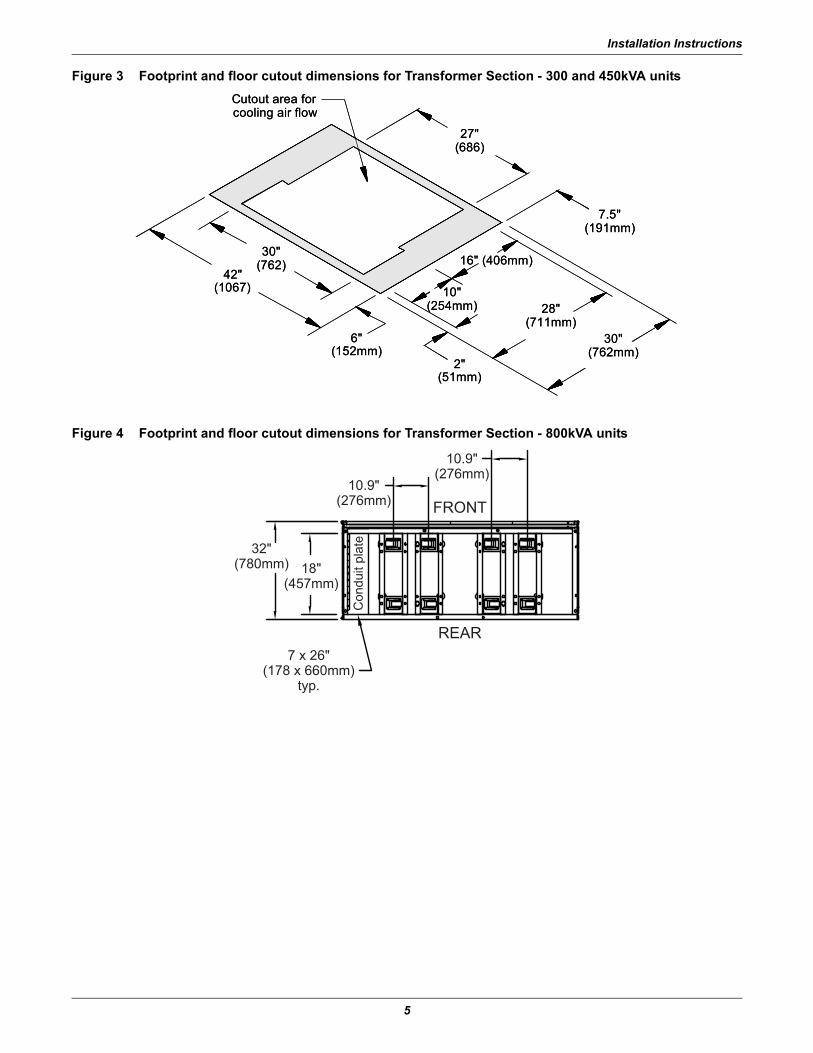
Figure 3 Footprint and floor cutout dimensions for Transformer Section - 300 and 450kVA units
Figure 4 Footprint and floor cutout dimensions for Transformer Section - 800kVA units
Cutout area forcooling air flow
16" (406mm)
10"(254mm) 28"
(711mm)30"
(762mm)2"
(51mm)
6"(152mm)
7.5"(191mm)
27"(686)
42"(1067)
30"(762)
Cutout area forcooling air flow
16" (406mm)
10"(254mm) 28"
(711mm)30"
(762mm)2"
(51mm)
6"(152mm)
7.5"(191mm)
27"(686)
42"(1067)
30"(762)
10.9"(276mm)
10.9"(276mm)
32"(780mm) 18"
(457mm)
7 x 26"(178 x 660mm)
typ.
REAR
FRONT
Con
duit
plat
e
Installation Instructions
6
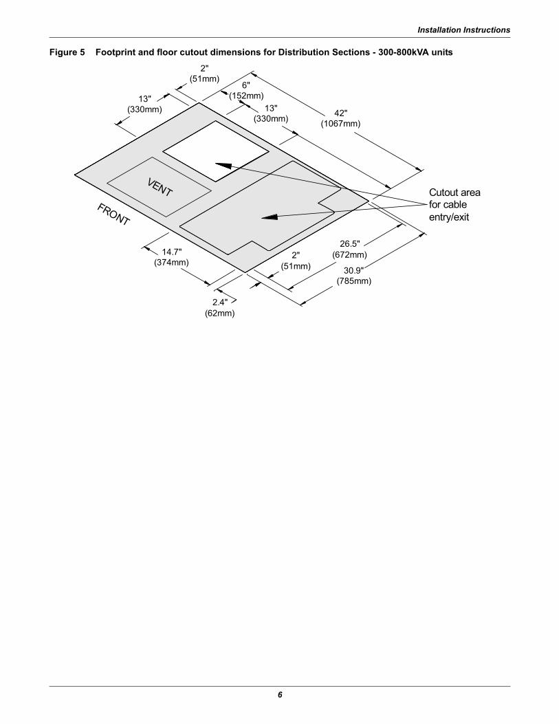
Figure 5 Footprint and floor cutout dimensions for Distribution Sections - 300-800kVA units
2"(51mm)
6"(152mm)
42"(1067mm)
26.5"(672mm)
30.9"(785mm)
2.4"(62mm)
14.7"(374mm)
13"(330mm)
2"(51mm)
13"(330mm)
Cutout areafor cableentry/exit
FRONT
VENT
Installation Instructions
7
1.2 Power and Control Wiring
Power and control wiring should be installed by licensed electricians. All power and control wiring must comply with the NEC and applicable local codes. Refer to Figures 6 and 7 for single-line diagrams.
1.2.1 Distribution Section Mounting and Wiring
Each 300 and 450kVA Liebert PPC requires a distribution section for routing input/output cables and to provide output distribution. Each 800kVA Liebert PPC requires two (2) distribution sections.
Distribution sections are shipped separate from the main unit. Each distribution section has base dimensions of 42 x 30 in. (1067 x 762mm) and should be mounted on the right side of the transformer section. Each 800kVA Liebert PPC requires one distribution section on each side on the transformer section.
Provide a floor cutout for exit of output cables, as shown in Figures 3, 4 and 5.
Align the distribution side section with the main unit and bolt the two frames together using the four bolts and hardware provided. See Figure 1 for 300-450kVA units and Figure 2 for 800kVA units.
300-450kVA units are shipped with a left side panel on the transformer section and a right side panel on the distribution section. 800kVA units ship with a left side panel on the left distribution section and a right side panel on the right side distribution section. The transformer section of an 800kVA unit ships without side panels.
After electrical connections are completed, install the side panels on the transformer and distribution section enclosures.
Installation Instructions
8
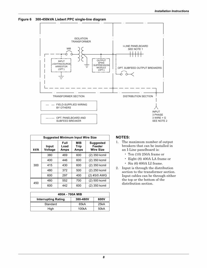
Figure 6 300-450kVA Liebert PPC single-line diagram
TRANSFORMER SECTION DISTRIBUTION SECTION
INPUT3 PHASE3 WIRE + GSEE NOTE 2
FIELD-SUPPLIED WIRINGBY OTHERS
OPT. PANELBOARD ANDSUBFEED BREAKER
ISOLATIONTRANSFORMER
OUTPUTSPIKE
SUPPRESSIONMODULE
(OPT.)
MIB
INPUTLIGHTING/SURGE
ARRESTOR(OPT.)
I-LINE PANELBOARDSEE NOTE 1
OPT. SUBFEED OUTPUT BREAKERS
Suggested Minimum Input Wire Size
kVAInput
Voltage
FullLoadAmps
MIBTrip
Amps
SuggestedFeeder
Wire Size
300
380 469 600 (2) 350 kcmil
400 446 600 (2) 350 kcmil
415 430 600 (2) 350 kcmil
480 372 500 (2) 250 kcmil
600 297 400 (2) #3/0 AWG
450480 552 700 (2) 500 kcmil
600 442 600 (2) 350 kcmil
400A - 700A MIB
Interrupting Rating 380-480V 600V
Standard 65kA 25kA
High 100kA 50kA
NOTES:1. The maximum number of output
breakers that can be installed in an I-Line panelboard is:
• Ten (10) 250A frame or• Eight (8) 400A LA frame or• Six (6) 600A LI frame.
2. Input is through the distribution section to the transformer section. Input cables can be through either the top or the bottom of the distribution section.
Installation Instructions
9
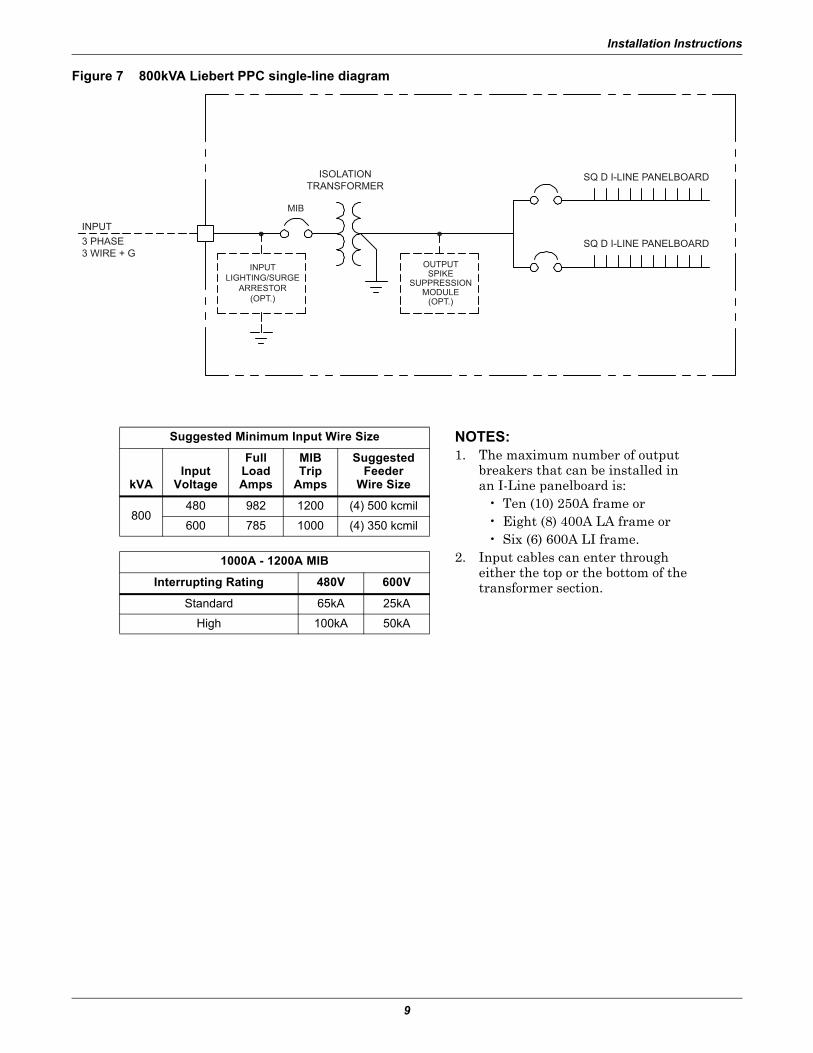
Figure 7 800kVA Liebert PPC single-line diagram
INPUT3 PHASE3 WIRE + G
ISOLATIONTRANSFORMER
OUTPUTSPIKE
SUPPRESSIONMODULE
(OPT.)
MIB
INPUTLIGHTING/SURGE
ARRESTOR(OPT.)
SQ D I-LINE PANELBOARD
SQ D I-LINE PANELBOARD
Suggested Minimum Input Wire Size
kVAInput
Voltage
FullLoadAmps
MIBTrip
Amps
SuggestedFeeder
Wire Size
800 480 982 1200 (4) 500 kcmil
600 785 1000 (4) 350 kcmil
1000A - 1200A MIB
Interrupting Rating 480V 600V
Standard 65kA 25kA
High 100kA 50kA
NOTES:1. The maximum number of output
breakers that can be installed in an I-Line panelboard is:
• Ten (10) 250A frame or• Eight (8) 400A LA frame or• Six (6) 600A LI frame.
2. Input cables can enter through either the top or the bottom of the transformer section.
Installation Instructions
10
1.2.2 Side-Section Electrical Connections
Five conductors (three-phase conductors, neutral and ground) are furnished with the distribution sec-tion for connection to the transformer section in the field, along with an intercabinet frame ground conductor.
For 300-450kVA units, the distribution section phase conductors are connected directly to the trans-former terminals:
• Phase A (wire 14) to X1• Phase B (wire 15) to X2• Phase C (wire 16) to X3
The distribution section neutral (wire 47) and ground (wire 50) conductors are connected to the trans-former section main ground bus bar (see unit wiring diagram shipped with unit).
For 800kVA units, each distribution section is fed from an output breaker mounted in the transformer section.
For 300-450kVA units with current monitoring, route each side-section conductor through the appro-priate current transformer (CT) in the main unit.
NOTEDistribution section conductors must pass through the current transformers in the same direction as the main unit panelboard conductors. Use the existing main unit panelboard wiring for reference.
Installation Instructions
11
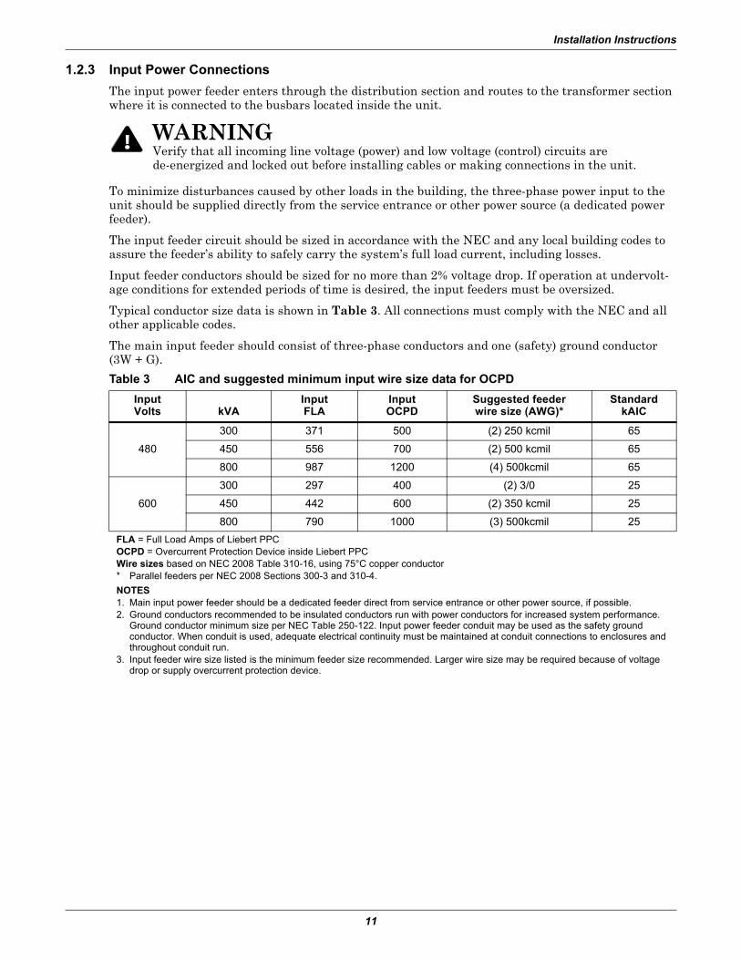
1.2.3 Input Power Connections
The input power feeder enters through the distribution section and routes to the transformer section where it is connected to the busbars located inside the unit.
To minimize disturbances caused by other loads in the building, the three-phase power input to the unit should be supplied directly from the service entrance or other power source (a dedicated power feeder).
The input feeder circuit should be sized in accordance with the NEC and any local building codes to assure the feeder’s ability to safely carry the system’s full load current, including losses.
Input feeder conductors should be sized for no more than 2% voltage drop. If operation at undervolt-age conditions for extended periods of time is desired, the input feeders must be oversized.
Typical conductor size data is shown in Table 3. All connections must comply with the NEC and all other applicable codes.
The main input feeder should consist of three-phase conductors and one (safety) ground conductor (3W + G).
! WARNINGVerify that all incoming line voltage (power) and low voltage (control) circuits are de-energized and locked out before installing cables or making connections in the unit.
Table 3 AIC and suggested minimum input wire size data for OCPD
InputVolts kVA
InputFLA
InputOCPD
Suggested feederwire size (AWG)*
StandardkAIC
480
300 371 500 (2) 250 kcmil 65
450 556 700 (2) 500 kcmil 65
800 987 1200 (4) 500kcmil 65
600
300 297 400 (2) 3/0 25
450 442 600 (2) 350 kcmil 25
800 790 1000 (3) 500kcmil 25
FLA = Full Load Amps of Liebert PPCOCPD = Overcurrent Protection Device inside Liebert PPCWire sizes based on NEC 2008 Table 310-16, using 75°C copper conductor* Parallel feeders per NEC 2008 Sections 300-3 and 310-4.
NOTES1. Main input power feeder should be a dedicated feeder direct from service entrance or other power source, if possible.2. Ground conductors recommended to be insulated conductors run with power conductors for increased system performance.
Ground conductor minimum size per NEC Table 250-122. Input power feeder conduit may be used as the safety ground conductor. When conduit is used, adequate electrical continuity must be maintained at conduit connections to enclosures and throughout conduit run.
3. Input feeder wire size listed is the minimum feeder size recommended. Larger wire size may be required because of voltage drop or supply overcurrent protection device.
Installation Instructions
12
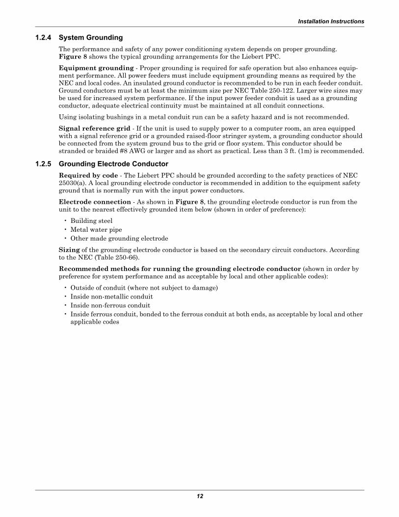
1.2.4 System Grounding
The performance and safety of any power conditioning system depends on proper grounding. Figure 8 shows the typical grounding arrangements for the Liebert PPC.
Equipment grounding - Proper grounding is required for safe operation but also enhances equip-ment performance. All power feeders must include equipment grounding means as required by the NEC and local codes. An insulated ground conductor is recommended to be run in each feeder conduit. Ground conductors must be at least the minimum size per NEC Table 250-122. Larger wire sizes may be used for increased system performance. If the input power feeder conduit is used as a grounding conductor, adequate electrical continuity must be maintained at all conduit connections.
Using isolating bushings in a metal conduit run can be a safety hazard and is not recommended.
Signal reference grid - If the unit is used to supply power to a computer room, an area equipped with a signal reference grid or a grounded raised-floor stringer system, a grounding conductor should be connected from the system ground bus to the grid or floor system. This conductor should be stranded or braided #8 AWG or larger and as short as practical. Less than 3 ft. (1m) is recommended.
1.2.5 Grounding Electrode Conductor
Required by code - The Liebert PPC should be grounded according to the safety practices of NEC 25030(a). A local grounding electrode conductor is recommended in addition to the equipment safety ground that is normally run with the input power conductors.
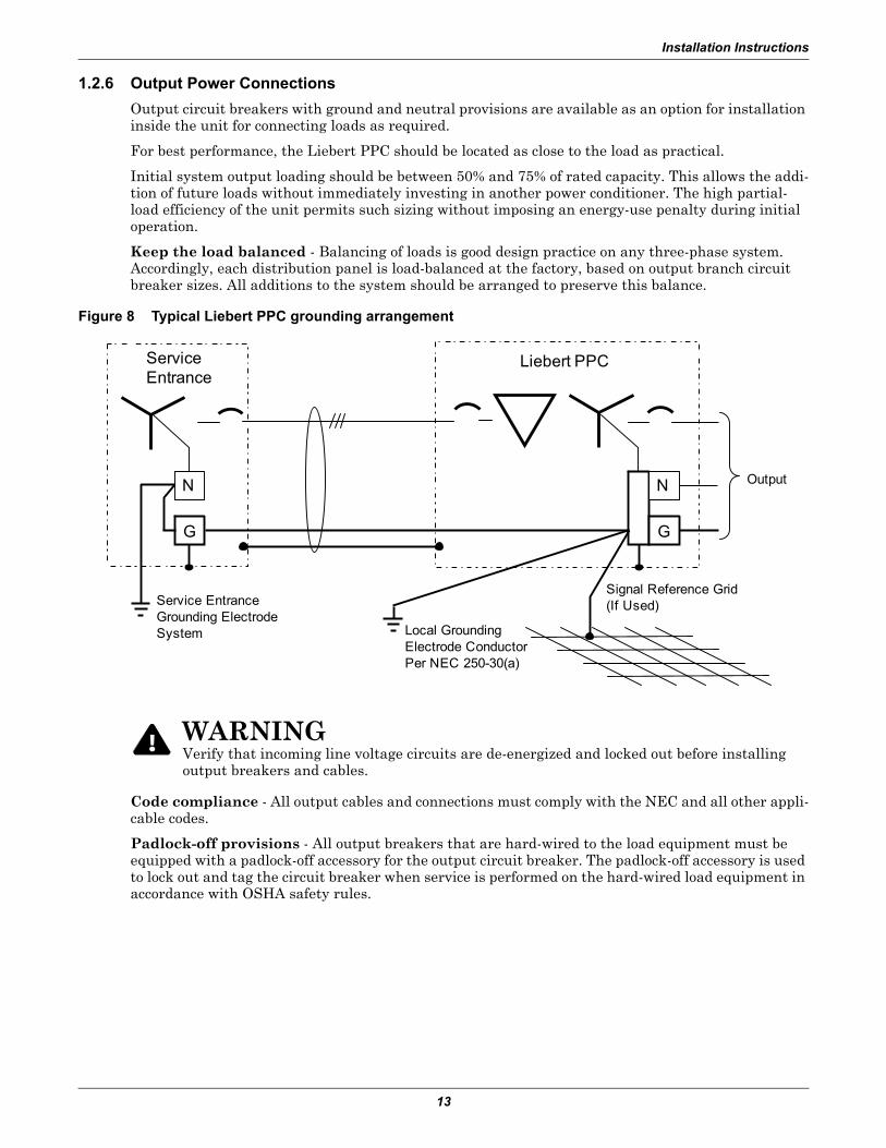
Electrode connection - As shown in Figure 8, the grounding electrode conductor is run from the unit to the nearest effectively grounded item below (shown in order of preference):
• Building steel• Metal water pipe• Other made grounding electrode
Sizing of the grounding electrode conductor is based on the secondary circuit conductors. According to the NEC (Table 250-66).
Recommended methods for running the grounding electrode conductor (shown in order by preference for system performance and as acceptable by local and other applicable codes):
• Outside of conduit (where not subject to damage)• Inside non-metallic conduit• Inside non-ferrous conduit• Inside ferrous conduit, bonded to the ferrous conduit at both ends, as acceptable by local and other
applicable codes
Installation Instructions
13
1.2.6 Output Power Connections
Output circuit breakers with ground and neutral provisions are available as an option for installation inside the unit for connecting loads as required.
For best performance, the Liebert PPC should be located as close to the load as practical.
Initial system output loading should be between 50% and 75% of rated capacity. This allows the addi-tion of future loads without immediately investing in another power conditioner. The high partial-load efficiency of the unit permits such sizing without imposing an energy-use penalty during initial operation.
Keep the load balanced - Balancing of loads is good design practice on any three-phase system. Accordingly, each distribution panel is load-balanced at the factory, based on output branch circuit breaker sizes. All additions to the system should be arranged to preserve this balance.
Figure 8 Typical Liebert PPC grounding arrangement
Code compliance - All output cables and connections must comply with the NEC and all other appli-cable codes.
Padlock-off provisions - All output breakers that are hard-wired to the load equipment must be equipped with a padlock-off accessory for the output circuit breaker. The padlock-off accessory is used to lock out and tag the circuit breaker when service is performed on the hard-wired load equipment in accordance with OSHA safety rules.
! WARNINGVerify that incoming line voltage circuits are de-energized and locked out before installing output breakers and cables.
ServiceEntrance
Liebert PPC
Output
Service EntranceGrounding ElectrodeSystem Local Grounding
Electrode ConductorPer NEC 250-30(a)
Signal Reference Grid(If Used)
NN
GG
Installation Instructions
14
1.2.7 Control Wiring Connections
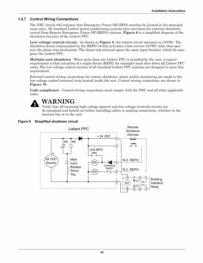
The NEC Article 645 requires that Emergency Power Off (EPO) switches be located at the principal room exits. All standard Liebert power conditioning systems have provision for external shutdown control from Remote Emergency Power Off (REPO) stations. Figure 9 is a simplified diagram of the shutdown circuitry of the Liebert PPC.
Low-voltage control circuit - As shown in Figure 9, the control circuit operates on 24VDC. The shutdown device (represented by the REPO switch) activates a low-current 24VDC relay that oper-ates the shunt-trip mechanism. The shunt-trip solenoid opens the main input breaker, which de-ener-gizes the Liebert PPC.
Multiple-unit shutdown - When more than one Liebert PPC is installed by the user, a typical requirement is that actuation of a single device (REPO, for example) must shut down all Liebert PPC units. The low-voltage control circuits of all standard Liebert PPC systems are designed to meet this requirement.
External control wiring connections for remote shutdown, alarm and/or monitoring are made to the low-voltage control terminal strip located inside the unit. Control wiring connections are shown in Figure 10.
Code compliance - Control wiring connections must comply with the NEC and all other applicable codes.
Figure 9 Simplified shutdown circuit
! WARNINGVerify that all incoming high-voltage (power) and low-voltage (control) circuits are de-energized and locked out before installing cables or making connections, whether in the junction box or in the unit.
MainInputBreakerShuntTrip
BuildingInterfaceRelay
N.O. REPO
RemoteShutdownDevices
24 VDCSource
K5
K6
7
9
A
B
4
6
1
3
1
4
5
2
3R1
Unit EPO
+ 24 VDC
OvertempSwitch
K5 K6
N.C. REPO
Liebert PPC
Installation Instructions
15
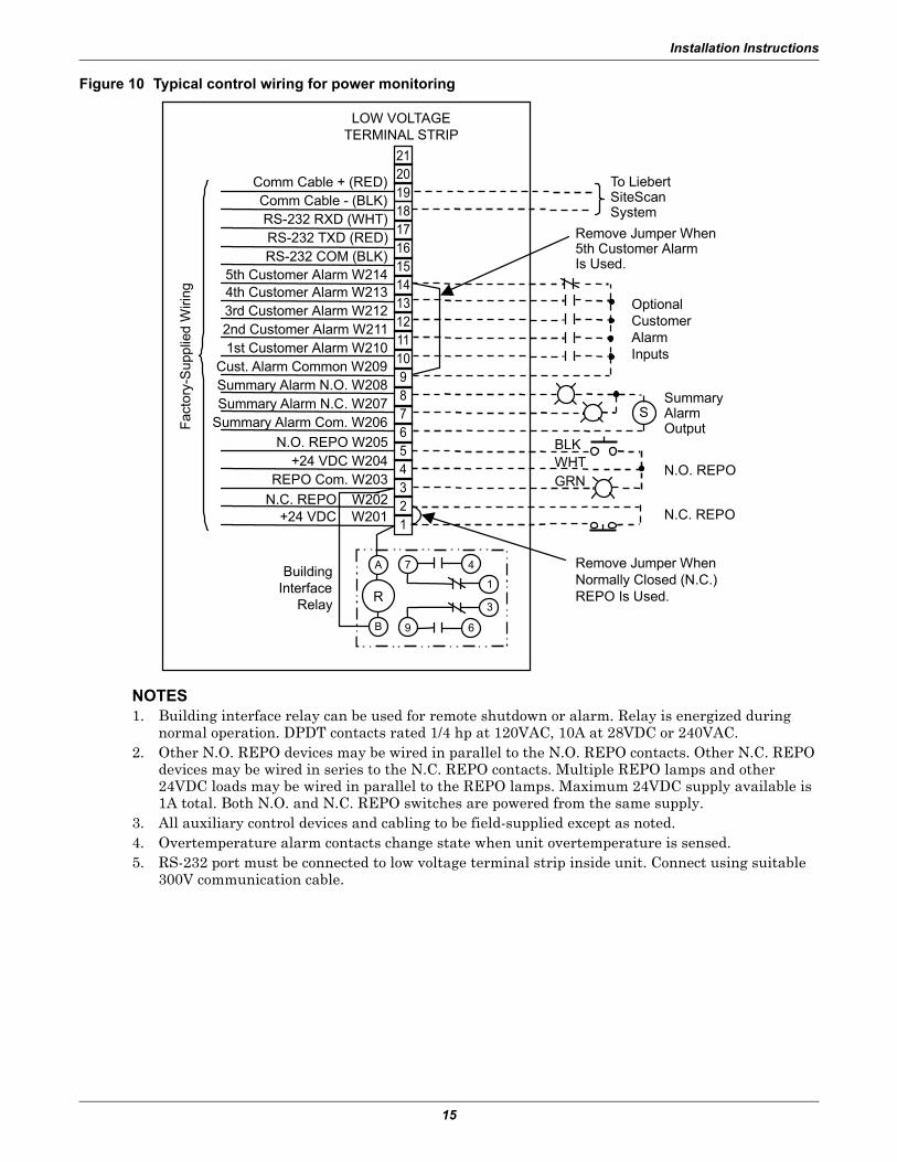
Figure 10 Typical control wiring for power monitoring
NOTES1. Building interface relay can be used for remote shutdown or alarm. Relay is energized during
normal operation. DPDT contacts rated 1/4 hp at 120VAC, 10A at 28VDC or 240VAC.2. Other N.O. REPO devices may be wired in parallel to the N.O. REPO contacts. Other N.C. REPO
devices may be wired in series to the N.C. REPO contacts. Multiple REPO lamps and other 24VDC loads may be wired in parallel to the REPO lamps. Maximum 24VDC supply available is 1A total. Both N.O. and N.C. REPO switches are powered from the same supply.
3. All auxiliary control devices and cabling to be field-supplied except as noted.4. Overtemperature alarm contacts change state when unit overtemperature is sensed.5. RS-232 port must be connected to low voltage terminal strip inside unit. Connect using suitable
300V communication cable.
BuildingInterface
Relay
N.O. REPO
N.C. REPO
OptionalCustomerAlarmInputs
SummaryAlarmOutput
To LiebertSiteScanSystem
Remove Jumper When5th Customer AlarmIs Used.
Remove Jumper WhenNormally Closed (N.C.)REPO Is Used.
WHTBLK
GRN
Comm Cable + (RED)Comm Cable - (BLK)RS-232 RXD (WHT)RS-232 TXD (RED)RS-232 COM (BLK)
5th Customer Alarm W2144th Customer Alarm W2133rd Customer Alarm W2122nd Customer Alarm W2111st Customer Alarm W210
Cust. Alarm Common W209Summary Alarm N.O. W208Summary Alarm N.C. W207
Summary Alarm Com. W206
N.O. REPO W205+24 VDC W204
REPO Com. W203
N.C. REPO W202+24 VDC W201
LOW VOLTAGETERMINAL STRIP
7
9
A
B
4
6
1
3R
S
Fac
tory
-Sup
plie
d W
iring
2120
181716151413121110987654321
19
Inspection and Startup Checklist
16
2.0 INSPECTION AND STARTUP CHECKLIST
Unit Serial Number: ___________________________________________________________
Unit Model Number: ___________________________________________________________
Date: _________________________________________________________________________
2.1 Internal Inspection Overview
A detailed internal inspection should be performed after the unit is in place and before it is energized, to ensure trouble-free startup. The same internal inspection should be carried out when performing preventive maintenance.
• Open the unit - Remove the exterior panels to gain access to the internal components of the Liebert PPC.
• Visually inspect - Check to make sure wiring and components are not damaged.• Check power connections - Check all power connections for tightness. Refer to Table 4 for
torque requirements of all electrical connections.• Perform formal detailed inspection - Follow the procedures described in the next section,
2.2 - Internal Inspection Procedure when performing detailed inspection.
2.2 Internal Inspection Procedure
EXTERIOR INSPECTION
___ 1. Confirm that the exterior of the unit is undamaged.
___ 2. Confirm that service and ventilation clearances are adequate (see Figures 1 and 2).
INTERIOR INSPECTION
___ 3. Remove accessible exterior panels.
___ 4. Inspect all wire and conductor insulation for damage.
___ 5. Check all transformer terminal connections for tightness. Retorque if necessary.
___ 6. Check all breaker connections for tightness. Retorque if necessary.
___ 7. Check all terminal block connections for tightness. Retorque if necessary.
___ 8. Check transformer mounting bolts for tightness. Retorque if necessary.
___ 9. Remove any foreign objects from the components and the interior area of the unit. Make sure air passages on transformers are clear and free of debris.
___ 10. Check that the intake and exhaust air screens are clean and free of obstructions.
___ 11. Replace side panels, leaving access to circuit breakers for the following startup procedure.
! WARNINGVerify that all incoming power and control circuits are de-energized and locked out before performing the internal inspection.
! WARNINGAll equipment inspection procedures are to be performed with power to the unit turned off and locked out.
NOTEWhen removing exterior panels, disconnect panel ground wires by separating the easy-disconnect terminals located on the frame. When replacing exterior panels, reconnect all panel ground wires.
NOTEWhen replacing the side panels, be sure to reconnect the panel ground wires.
Inspection and Startup Checklist
17
2.3 Startup and Monitoring System Check Overview
Checklists - Follow the detailed step-by-step instructions in the following two sections when install-ing and starting up the Liebert PPC:
• 2.4 - Startup Procedure• 2.5 - Monitoring System Check
Initial system startup - A qualified electrician should be employed to perform the equipment inspection and startup. Liebert system startup may be arranged by contacting your local Emerson sales representative or Emerson Network Power Liebert Services at 1-800-543-2378.
Warranty - A copy of the checklist furnished with the unit must be completed, signed, dated and returned to Emerson Network Power (see Section 2.6). Warranty coverage of the equipment is not effective unless the checklist is received by the factory.
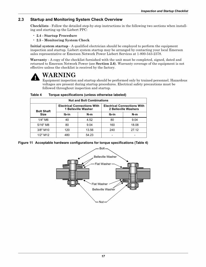
Figure 11 Acceptable hardware configurations for torque specifications (Table 4)
! WARNINGEquipment inspection and startup should be performed only by trained personnel. Hazardous voltages are present during startup procedures. Electrical safety precautions must be followed throughout inspection and startup.
Table 4 Torque specifications (unless otherwise labeled)
Nut and Bolt Combinations
Bolt ShaftSize
Electrical Connections With1 Belleville Washer
Electrical Connections With2 Belleville Washers
lb-in N-m lb-in N-m
1/4" M6 40 4.52 80 9.04
5/16" M8 80 9.04 160 18.08
3/8" M10 120 13.56 240 27.12
1/2" M12 480 54.23 - -
Flat Washer
Bolt
Belleville Washer
Belleville Washer
Flat Washer
Nut

Inspection and Startup Checklist
18
2.4 Startup Procedure
___ 1. Make certain that all circuit breakers are in the Off position and that power to the unit is locked out.___ 2. Verify proper input power connections to unit, including equipment grounding conductor and local
grounding electrode conductor.___ 3. Turn On the building input power to the unit.___ 4. Check the phase rotation at the main input breaker. Phase rotation should be A, B, C, left-to-right.___ 5. Check and record the input voltage at the main input breaker. Measured voltages should correspond
to the unit’s nameplate input voltage.Volts, phase A to phase B =__________Volts, phase B to phase C =__________Volts, phase C to phase A =__________
___ 6. Turn On the main input breaker; wait one minute. (If breaker trips Off, check for wiring errors including control connections. Contact Liebert Services or the location factory representative for assistance.)
___ 7. Check the phase rotation at the line side terminals of the panelboard or panelboard main breaker(s). The rotation should be A, B, C, left-to-right.
___ 8. Check and record the voltages at the line-side terminals of the output circuit breaker. Measured voltages should correspond to the unit’s nameplate output voltage (within +4%, 0%).
Volts, phase A to phase B =__________Volts, phase B to phase C =__________Volts, phase C to phase A =__________Volts, phase A to neutral =__________Volts, phase B to neutral =__________Volts, phase C to neutral =__________
If output voltage is incorrect, check for wiring errors, incorrect input voltage, or improper transformer tap. Contact Liebert Services at 1-800-543-2378 or your local Emerson representative for assistance.
___ 9. Depress the local Emergency Power Off (EPO) switch and verify system shutdown. Turn the unit back on.
___ 10. If the system is equipped with any Remote Emergency Power Off (REPO) switches, test each to ensure proper operation. Note that the REPO switch may shut down more equipment or systems than just the Liebert PPC.
! WARNINGStartup procedures should be performed only by qualified personnel. Hazardous voltages are present in the equipment throughout the majority of the startup procedure. Use proper safety equipment. Proceed with caution.
NOTEThe Liebert PPC transformer has input voltage taps for each input phase:
• For 300kVA units, the taps are arranged in 2-1/2% increments. Taps include: two above nominal voltage (upper range limit of +5%) and four below nominal voltage (lower range limit of -10%).
• For 450kVA units, the taps are arranged in 3% increments. Taps include: two above nominal voltage (upper range limit of +6%) and three below nominal voltage (lower range limit of -9%).
• For 800kVA units, the taps are arranged in 4% increments. Taps include: two above nominal voltage (upper range limit of +8%) and two below nominal voltage (lower range limit of -8%).
This permits the transformer to provide the proper output voltage for a range of input voltages. Should it be necessary, the tap arrangement may be changed to match the input voltage:
a. Open the main input circuit breaker.b. Select tap arrangement to match input voltage. (Refer to transformer nameplate for tap
information.)c. Secure each line to its proper tap.d. Repeat Steps 6 to 8.
Inspection and Startup Checklist
19
2.5 Monitoring System Check___ 1. Basic Indicators:
a. Turn On the building power to the unit, then turn the main input breaker On.b. Check that the local Emergency Power Off button is illuminated and the Alarm Present
button is off (not illuminated).
___ 2. Manual Restart Check - if the unit is equipped with manual restart:a. Turn on building power to the unit. Turn the main input breaker On.b. Turn off all building power to the unit.c. Observe that the main input breaker automatically trips open upon power loss.d. Restore building power to the unit and return the main input breaker to On.
___ 3. Power Monitor Panel: a. Turn the unit On.b. Ensure that the voltage values indicated by the Monitor Panel correspond to the voltage
values measured at the main input circuit breaker (Step 5 in 2.4 - Startup Procedure) and output circuit breaker (Step 8 in 2.4 - Startup Procedure).
___ 4. Centralized Monitoring System - if the unit is connected to a centralized monitoring system: a. Turn the unit and centralized monitoring system On.b. Verify proper communication to the monitor system operation.
___ 5. Control Voltage: a. Obtain access to the low voltage terminals in the low voltage control section inside the unit.b. With the unit On, measure and record the DC control voltage on terminals 1 (+) and 3 (com).c. Control voltage = ________ (Voltage should be between 20 and 28VDC).
___ 6. Customer Alarms: a. With the unit On, simulate alarm operation by jumpering the appropriate low voltage control
terminals. (Refer to the control wiring installation drawing furnished with the unit.)b. Verify correct alarm operation by the Power Monitor Panel and/or by the centralized
monitoring system.
2.6 Send Completed Checklist to Emerson Network Power
After performing all procedures described in this section, 2.0 - Inspection and Startup Checklist, sign, date and return the completed Inspection and Startup Checklist form furnished with the unit to:
Emerson Network Power1050 Dearborn DriveP.O. Box 29186Columbus, Ohio 43229 USA
NOTEWarranty is not in effect unless the Inspection and Startup Checklist form is received by the factory.
Operating Instructions
20
3.0 OPERATING INSTRUCTIONS
3.1 Startup Procedures
Before the unit is placed into service after initial installation, after equipment relocation or after equipment has been de-energized for an extended period of time, perform equipment inspection and startup procedures as detailed in 2.0 - Inspection and Startup Checklist.
After initial system startup, use the following guidelines for standard equipment operation. These guidelines should be reviewed for any special equipment modifications, special site considerations or company policies that may require changes to the standard equipment operation.
3.1.1 Emergency Shutdown
To perform an immediate system shutdown during emergency conditions, lift the protective clear cover and push the EPO switch on the front door of the unit.
If the site is equipped with a REPO switch—for example, as required by NEC Article 645 at the prin-cipal exit doors—activate one of the REPO switches to perform an immediate room shutdown.
3.1.2 Normal System Shutdown
To perform a normal system shutdown
• Shut down the load equipment—for example, a computer system—according to the manufac-turer’s recommendations. The load equipment can be turned Off at each piece of load equipment or at the Liebert PPC’s output distribution (circuit breaker) panels located behind the unit’s front door.
• Turn Off all unit output breakers, then turn Off the unit’s main input circuit breaker.• To remove all power from the unit, turn Off the building power to the unit’s input breaker or junc-
tion box.
NOTEDepending on the control circuit wiring, operation of the unit EPO switch may cause other equipment to shut down.
Operating Instructions
21
3.1.3 Normal System Startup
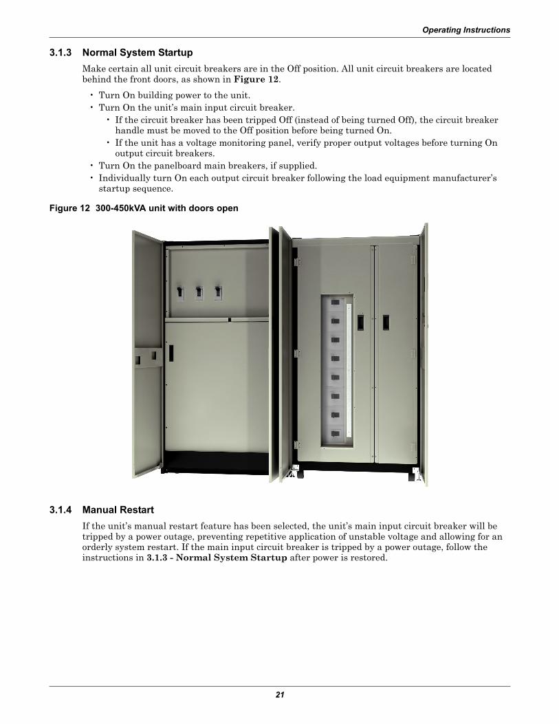
Make certain all unit circuit breakers are in the Off position. All unit circuit breakers are located behind the front doors, as shown in Figure 12.
• Turn On building power to the unit.• Turn On the unit’s main input circuit breaker.
• If the circuit breaker has been tripped Off (instead of being turned Off), the circuit breaker handle must be moved to the Off position before being turned On.
• If the unit has a voltage monitoring panel, verify proper output voltages before turning On output circuit breakers.
• Turn On the panelboard main breakers, if supplied.• Individually turn On each output circuit breaker following the load equipment manufacturer’s
startup sequence.
Figure 12 300-450kVA unit with doors open
3.1.4 Manual Restart
If the unit’s manual restart feature has been selected, the unit’s main input circuit breaker will be tripped by a power outage, preventing repetitive application of unstable voltage and allowing for an orderly system restart. If the main input circuit breaker is tripped by a power outage, follow the instructions in 3.1.3 - Normal System Startup after power is restored.
Operating Instructions
22
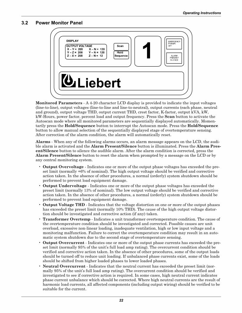
3.2 Power Monitor Panel
Monitored Parameters - A 4-20 character LCD display is provided to indicate the input voltages (line-to-line), output voltages (line-to-line and line-to-neutral), output currents (each phase, neutral and ground), output voltage THD, output current THD, crest factor, K-factor, output kVA, kW, kW-Hours, power factor, percent load and output frequency. Press the Scan button to activate the Autoscan mode where all monitored parameters are sequentially displayed automatically. Momen-tarily press the Hold/Sequence button to interrupt the Autoscan mode. Press the Hold/Sequence button to allow manual selection of the sequentially displayed stage of overtemperature sensing. After correction of the alarm condition, the alarm will automatically reset.
Alarms - When any of the following alarms occurs, an alarm message appears on the LCD, the audi-ble alarm is activated and the Alarm Present/Silence button is illuminated. Press the Alarm Pres-ent/Silence button to silence the audible alarm. After the alarm condition is corrected, press the Alarm Present/Silence button to reset the alarm when prompted by a message on the LCD or by any central monitoring system.
• Output Overvoltage - Indicates one or more of the output phase voltages has exceeded the pre-set limit (normally +6% of nominal). The high output voltage should be verified and corrective action taken. In the absence of other procedures, a normal (orderly) system shutdown should be performed to prevent load equipment damage.
• Output Undervoltage - Indicates one or more of the output phase voltages has exceeded the preset limit (normally 13% of nominal). The low output voltage should be verified and corrective action taken. In the absence of other procedures, a normal (orderly) system shutdown should be performed to prevent load equipment damage.
• Output Voltage THD - Indicates that the voltage distortion on one or more of the output phases has exceeded the preset limit (normally 10% THD). The cause of the high output voltage distor-tion should be investigated and corrective action (if any) taken.
• Transformer Overtemp - Indicates a unit transformer overtemperature condition. The cause of the overtemperature condition should be investigated and corrected. Possible causes are unit overload, excessive non-linear loading, inadequate ventilation, high or low input voltage and a monitoring malfunction. Failure to correct the overtemperature condition may result in an auto-matic system shutdown due to the second stage of overtemperature sensing.
• Output Overcurrent - Indicates one or more of the output phase currents has exceeded the pre-set limit (normally 95% of the unit’s full load amp rating). The overcurrent condition should be verified and corrective action taken. In the absence of other procedures, some of the output loads should be turned off to reduce unit loading. If unbalanced phase currents exist, some of the loads should be shifted from higher loaded phases to lower loaded phases.
• Neutral Overcurrent - Indicates that the neutral current has exceeded the preset limit (nor-mally 95% of the unit’s full load amp rating). The overcurrent condition should be verified and investigated to see if corrective action is required. In some cases, high neutral current indicates phase current unbalance which should be corrected. Where high neutral currents are the result of harmonic load currents, all affected components (including output wiring) should be verified to be suitable for the current.
Operating Instructions
23
• Frequency Deviation - Indicates that the output frequency has exceeded preset limits (normally 0.5Hz). The frequency deviation should be verified and the cause investigated and corrected.
• Phase Sequence Error - Indicates that the output phase sequence is not A, B, C. The phase sequence should be verified and corrective action taken. Three-phase loads sensitive to phase sequence should not be operated without proper phase sequence.
• Phase Loss - Indicates that one or more of the phase voltages is low or missing. The low voltage condition should be verified and corrective action taken. In the absence of other procedures, a nor-mal (orderly) shutdown should be performed to prevent equipment damage.
• Ground Overcurrent - Indicates the system ground current has exceeded the preset limit (nor-mally 5A). The overcurrent condition should be verified and corrective action taken. Possible causes are wiring errors, ground faults and excessive leakage current.
• Customer Alarms (5) - Indicates customer-designated alarms. The cause and corrective action depend on the nature of the alarm. See 1.2.7 - Control Wiring Connections for contact closure connection information.
To Set Clock/Language Selection - To set the clock or change the language selection from the unit front panel, simultaneously press the Scan and Hold membrane buttons while the time and date screen is displayed on the LCD. A cursor appears on the selected time and date field. Use the Scan button to increment the highlighted field and the Hold button to decrement the highlighted field. Use the Silence push button to select the next time and date field. The time can be displayed in AM/PM or 24-hour format. Simultaneously press the Scan and Hold buttons to exit the clock/language set screens.
RS-232 ASCII Communications Port - Units with power monitoring are equipped with an isolated RS-232 ASCII communications port, which allows access to unit-monitored parameters and alarm information. The RS-232 port connections are located on the low voltage control terminal strip inside the unit. See typical control wiring in Figure 10.
The ASCII interface default parameters are as follows:
The ASCII port uses a Query-Response Format.
Interface RS-232 Using EIA Voltage Levels
Baud Rate 9600
Parity None
Data Bits 8
Stop Bits 1
Terminator <CR>
Hand Shaking Not Supported
Structure Half-Duplex
Echo Off
Change to Receive After Transmit 1.28 msec
Minimum Delay to Transmit After Receive 120 sec
Maximum Response Time Turnaround 300 msec
Maximum Response Completion Time 500 msec
Minimum Delay Between Commands 500 msec
Maximum Intercharacter Delay 12.5 msec
Operating Instructions
24
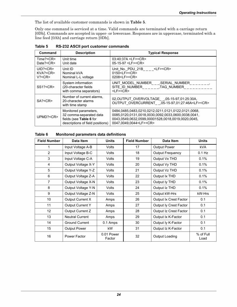
The list of available customer commands is shown in Table 5.
Only one command is serviced at a time. Valid commands are terminated with a carriage return [0Dh]. Commands are accepted in upper- or lowercase. Responses are in uppercase, terminated with a line feed [0Ah] and carriage return [0Dh].
Table 5 RS-232 ASCII port customer commands
Command Description Typical Response
Time?<CR>Date?<CR>
Unit timeUnit date
03:40:37A <LF><CR>05-15-97 <LF><CR>
UID?<CR>KVA?<CR>V?<CR>
Unit IDNominal kVANominal L-L voltage
Unit_No._PDU_21B_ _ _ _<LF><CR>0150<LF><CR>0208<LF><CR>
SS1?<CR>System information(20-character fields with comma separators)
UNIT_MODEL_NUMBER_ _ _,SERIAL_NUMBER_ _ _ _ _ _ _,SITE_ID_NUMBER_ _ _ _ _ _,TAG_NUMBER_ _ _ _ _ _ _ _ _ _<LF><CR>
SA?<CR>Number of current alarms,20-character alarms with time stamp
02,OUTPUT_OVERVOLTAGE_ _,05-15-97,01:25:30A,OUTPUT_OVERCURRENT_ _,05-15-97,01:27:46A<LF><CR>
UPMD?<CR>
Monitored parameters, 32 comma-separated datafields (see Table 6 for descriptions of field positions)
0484,0485,0483,0210,0212,0211,0121,0122,0121,0068,0085,0120,0131,0018,0030,0092,0033,0600,0038,0041,0043,0549,0632,0599,00001528,0018,0019,0020,0045, 0047,0049,0044<LF><CR>
Table 6 Monitored parameters data definitions
Field Number Data Item Units Field Number Data Item Units
1 Input Voltage A-B Volts 17 Output Power kVA
2 Input Voltage B-C Volts 18 Output Frequency 0.1 Hz
3 Input Voltage C-A Volts 19 Output Vx THD 0.1%
4 Output Voltage X-Y Volts 20 Output Vy THD 0.1%
5 Output Voltage Y-Z Volts 21 Output Vz THD 0.1%
6 Output Voltage Z-A Volts 22 Output Ix THD 0.1%
7 Output Voltage X-N Volts 23 Output Iy THD 0.1%
8 Output Voltage Y-N Volts 24 Output Iz THD 0.1%
9 Output Voltage Z-N Volts 25 Output kW-Hrs kW-Hrs
10 Output Current X Amps 26 Output Ix Crest Factor 0.1
11 Output Current Y Amps 27 Output Iy Crest Factor 0.1
12 Output Current Z Amps 28 Output Iz Crest Factor 0.1
13 Neutral Current Amps 29 Output Ix K-Factor 0.1
14 Ground Current 0.1 Amps 30 Output Iy K-Factor 0.1
15 Output Power kW 31 Output Iz K-Factor 0.1
16 Power Factor0.01 Power
Factor32 Output Loading
% of FullLoad

Maintenance
25
4.0 MAINTENANCE
4.1 Corrective Maintenance (Repair)
Even the most reliable equipment may fail. Contact Liebert Services for fast repair of your unit and minimum downtime of your installation.
Standard electrical troubleshooting procedures should be used to isolate problems in the unit. If there are questions, contact Liebert Services.
Repair or replacement of standard items, such as circuit breakers, fuses, transformers, capacitors and indicator lights can be either handled by qualified electricians or referred to Liebert Services.
Repairs related to the monitoring system should be referred to Liebert Services.
To contact Liebert Services for information or repair service, call 1-800-543-2378.
! WARNINGOnly qualified service personnel should perform maintenance on the Liebert PPC.
Maintenance
26
4.2 Preventive Maintenance (Inspection & Cleaning)
Air circulation through the cabinet may cause dust to accumulate on internal components. Cleaning should be done as necessary during electrical inspections.
Annual general system inspections, cleaning and operation checks are recommended to ensure sys-tem performance and long service life.
4.2.1 Inspection Schedule
• It is difficult to establish a schedule for periodic cleanings since conditions vary from site to site. Inspections after the first 24 hours, 30 days and 6 months of operation should help determine a pattern for the inspection schedule.
• Electrical connections and component mountings should be inspected after the first 24 hours, 30 days and 6 months of operation. Inspections should be conducted annually thereafter.
• Ventilation openings and grilles should be inspected and cleaned every six months to one year.• A complete inspection and operational checkout should be performed annually. This is best done
by performing the inspection and startup procedures outlined in 2.0 - Inspection and Startup Checklist.
• Liebert Services offers a complete range of preventive maintenance services. These include thorough equipment performance checks and calibration of electronics. Contact Liebert Services at 1-800-543-2378 for details.
! WARNINGOnly qualified service personnel should perform maintenance on the Liebert PPC. All voltage sources to the unit must be disconnected before inspecting or cleaning within the cabinet.


Ensuring The High AvailabilityOf Mission-Critical Data And Applications.
Emerson Network Power, a business of Emerson (NYSE:EMR),is the global leader in enabling Business-Critical Continuity™
from grid to chip for telecommunication networks, data centers,health care and industrial facilities. Emerson Network Powerprovides innovative solutions and expertise in areas includingAC and DC power and precision cooling systems, embeddedcomputing and power, integrated racks and enclosures,power switching and controls, infrastructure management,and connectivity. All solutions are supported globally by localEmerson Network Power service technicians. Liebert AC power,precision cooling and monitoring products and servicesfrom Emerson Network Power deliver Efficiency Without Compromise™ by helping customers optimize their data center infrastructure to reduce costs and deliver high availability.
While every precaution has been taken to ensure the accuracyand completeness of this literature, Liebert Corporation assumes noresponsibility and disclaims all liability for damages resulting from use ofthis information or for any errors or omissions.© 2010 Liebert CorporationAll rights reserved throughout the world. Specifications subject to changewithout notice.® Liebert is a registered trademark of Liebert Corporation.All names referred to are trademarksor registered trademarks of their respective owners.
Technical Support / ServiceWeb Site
www.liebert.comMonitoring
Outside North America: +00800 1155 4499Single-Phase UPS & Server Cabinets
Outside North America: +00800 1155 4499Three-Phase UPS & Power Systems
800-543-2378Outside North America: 614-841-6598
Environmental Systems800-543-2778
Outside the United States: 614-888-0246
LocationsUnited States
1050 Dearborn DriveP.O. Box 29186
Columbus, OH 43229Europe
Via Leonardo Da Vinci 8Zona Industriale Tognana
35028 Piove Di Sacco (PD) Italy+39 049 9719 111
Fax: +39 049 5841 257Asia
29/F, The Orient Square BuildingF. Ortigas Jr. Road, Ortigas Center
Pasig City 1605Philippines
+63 2 687 6615Fax: +63 2 730 9572
Emerson Network Power. The global leader in enabling Business-Critical Continuity™ EmersonNetworkPower.com
Emerson, Business-Critical Continuity, Emerson Network Power and the Emerson Network Power logo are trademarks of Emerson Electric Co. or one of its affiliated companies.©2010 Emerson Electric Co.
AC Power
Connectivity
DC Power
Embedded Computing
Embedded Power
Infrastructure Management & Monitoring
Outside Plant
Power Switching & Controls
Precision Cooling
Racks & Integrated Cabinets
Services
Surge Protection
SL-20048 _REV0_09-10