Embed Size (px)
Citation preview
AC PowerFor Business-Critical Continuity™
Liebert® GXT3-10000T230™
User Manual–10kVA, 50/60 Hz, 230V


i
TABLE OF CONTENTS
IMPORTANT SAFETY INSTRUCTIONS . . . . . . . . . . . . . . . . . . . . . . . . . . . . . . . . . . . . . . . . . . . . . . . .1
1.0 INTRODUCTION AND SYSTEM DESCRIPTION . . . . . . . . . . . . . . . . . . . . . . . . . . . . . . . . . . . . .41.1 Device Overview . . . . . . . . . . . . . . . . . . . . . . . . . . . . . . . . . . . . . . . . . . . . . . . . . . . . . . . . . . . . . 4
1.2 Options . . . . . . . . . . . . . . . . . . . . . . . . . . . . . . . . . . . . . . . . . . . . . . . . . . . . . . . . . . . . . . . . . . . . 51.2.1 External Battery Cabinets . . . . . . . . . . . . . . . . . . . . . . . . . . . . . . . . . . . . . . . . . . . . . . . . . . . . . . 51.2.2 Optional Interfaces . . . . . . . . . . . . . . . . . . . . . . . . . . . . . . . . . . . . . . . . . . . . . . . . . . . . . . . . . . . . 5
2.0 UNPACKING THE UPS AND SITE PREPARATION . . . . . . . . . . . . . . . . . . . . . . . . . . . . . . . . . .62.1 Inspection . . . . . . . . . . . . . . . . . . . . . . . . . . . . . . . . . . . . . . . . . . . . . . . . . . . . . . . . . . . . . . . . . . 6
2.2 Required Setup Equipment . . . . . . . . . . . . . . . . . . . . . . . . . . . . . . . . . . . . . . . . . . . . . . . . . . . . 6
2.3 Unpacking. . . . . . . . . . . . . . . . . . . . . . . . . . . . . . . . . . . . . . . . . . . . . . . . . . . . . . . . . . . . . . . . . . 6
2.4 Storage . . . . . . . . . . . . . . . . . . . . . . . . . . . . . . . . . . . . . . . . . . . . . . . . . . . . . . . . . . . . . . . . . . . . 6
2.5 Handling . . . . . . . . . . . . . . . . . . . . . . . . . . . . . . . . . . . . . . . . . . . . . . . . . . . . . . . . . . . . . . . . . . . 6
2.6 Environmental Conditions. . . . . . . . . . . . . . . . . . . . . . . . . . . . . . . . . . . . . . . . . . . . . . . . . . . . . 7
2.7 Access required. . . . . . . . . . . . . . . . . . . . . . . . . . . . . . . . . . . . . . . . . . . . . . . . . . . . . . . . . . . . . . 7
2.8 Floor/Rack Loading . . . . . . . . . . . . . . . . . . . . . . . . . . . . . . . . . . . . . . . . . . . . . . . . . . . . . . . . . . 7
2.9 Inventory List . . . . . . . . . . . . . . . . . . . . . . . . . . . . . . . . . . . . . . . . . . . . . . . . . . . . . . . . . . . . . . . 7
2.10 Clearance . . . . . . . . . . . . . . . . . . . . . . . . . . . . . . . . . . . . . . . . . . . . . . . . . . . . . . . . . . . . . . . . . . 7
2.11 Repacking the UPS. . . . . . . . . . . . . . . . . . . . . . . . . . . . . . . . . . . . . . . . . . . . . . . . . . . . . . . . . . . 7
3.0 INSTALLATION . . . . . . . . . . . . . . . . . . . . . . . . . . . . . . . . . . . . . . . . . . . . . . . . . . . . . . . . . .83.1 Electrical preparations. . . . . . . . . . . . . . . . . . . . . . . . . . . . . . . . . . . . . . . . . . . . . . . . . . . . . . . . 8
3.2 Current Table and Suggested Cable Sizes . . . . . . . . . . . . . . . . . . . . . . . . . . . . . . . . . . . . . . . . 8
3.3 Neutral Connection . . . . . . . . . . . . . . . . . . . . . . . . . . . . . . . . . . . . . . . . . . . . . . . . . . . . . . . . . . 9
3.4 External Protection and Isolating Devices . . . . . . . . . . . . . . . . . . . . . . . . . . . . . . . . . . . . . . . . 9
3.5 Installation of Differential Protection Devices . . . . . . . . . . . . . . . . . . . . . . . . . . . . . . . . . . . . 10
3.6 External Electrical Connections . . . . . . . . . . . . . . . . . . . . . . . . . . . . . . . . . . . . . . . . . . . . . . . 10
3.7 Connecting Mains and Load . . . . . . . . . . . . . . . . . . . . . . . . . . . . . . . . . . . . . . . . . . . . . . . . . . 11
3.8 Terminal Blocks for UPS . . . . . . . . . . . . . . . . . . . . . . . . . . . . . . . . . . . . . . . . . . . . . . . . . . . . . 12
3.9 Connecting Power Cables. . . . . . . . . . . . . . . . . . . . . . . . . . . . . . . . . . . . . . . . . . . . . . . . . . . . . 12
3.10 External Tower Batteries. . . . . . . . . . . . . . . . . . . . . . . . . . . . . . . . . . . . . . . . . . . . . . . . . . . . . 13
3.11 Connecting an External Battery Extension . . . . . . . . . . . . . . . . . . . . . . . . . . . . . . . . . . . . . . 13
3.12 Battery Precautions . . . . . . . . . . . . . . . . . . . . . . . . . . . . . . . . . . . . . . . . . . . . . . . . . . . . . . . . . 14
3.13 Configuration Program . . . . . . . . . . . . . . . . . . . . . . . . . . . . . . . . . . . . . . . . . . . . . . . . . . . . . . 14
3.14 Liebert GXT3-10000T230 Configuration Program Features . . . . . . . . . . . . . . . . . . . . . . . . . 14
3.15 What You Will Need. . . . . . . . . . . . . . . . . . . . . . . . . . . . . . . . . . . . . . . . . . . . . . . . . . . . . . . . . 14

ii
4.0 OPERATION . . . . . . . . . . . . . . . . . . . . . . . . . . . . . . . . . . . . . . . . . . . . . . . . . . . . . . . . . . .154.1 Normal Operating . . . . . . . . . . . . . . . . . . . . . . . . . . . . . . . . . . . . . . . . . . . . . . . . . . . . . . . . . . 15
4.1.1 Block diagram. . . . . . . . . . . . . . . . . . . . . . . . . . . . . . . . . . . . . . . . . . . . . . . . . . . . . . . . . . . . . . . 15
4.2 Control Panel . . . . . . . . . . . . . . . . . . . . . . . . . . . . . . . . . . . . . . . . . . . . . . . . . . . . . . . . . . . . . . 164.2.1 Controls and Messages. . . . . . . . . . . . . . . . . . . . . . . . . . . . . . . . . . . . . . . . . . . . . . . . . . . . . . . . 164.2.2 Warning Indicators. . . . . . . . . . . . . . . . . . . . . . . . . . . . . . . . . . . . . . . . . . . . . . . . . . . . . . . . . . . 194.2.3 Fault Indicators . . . . . . . . . . . . . . . . . . . . . . . . . . . . . . . . . . . . . . . . . . . . . . . . . . . . . . . . . . . . . 20
4.3 Startup Preparations . . . . . . . . . . . . . . . . . . . . . . . . . . . . . . . . . . . . . . . . . . . . . . . . . . . . . . . . 20
4.4 UPS Startup Procedure - Single Block . . . . . . . . . . . . . . . . . . . . . . . . . . . . . . . . . . . . . . . . . . 21
4.5 UPS Shutdown Procedure—All Ratings . . . . . . . . . . . . . . . . . . . . . . . . . . . . . . . . . . . . . . . . . 21
4.6 Maintenance Bypass Procedure. . . . . . . . . . . . . . . . . . . . . . . . . . . . . . . . . . . . . . . . . . . . . . . . 21
4.7 Return from Maintenance Bypass Procedure . . . . . . . . . . . . . . . . . . . . . . . . . . . . . . . . . . . . . 22
4.8 Functional Test. . . . . . . . . . . . . . . . . . . . . . . . . . . . . . . . . . . . . . . . . . . . . . . . . . . . . . . . . . . . . 22
4.9 Remote Emergency Power Off . . . . . . . . . . . . . . . . . . . . . . . . . . . . . . . . . . . . . . . . . . . . . . . . . 22
4.10 Self-Tests. . . . . . . . . . . . . . . . . . . . . . . . . . . . . . . . . . . . . . . . . . . . . . . . . . . . . . . . . . . . . . . . . . 234.10.1 Lamp Test . . . . . . . . . . . . . . . . . . . . . . . . . . . . . . . . . . . . . . . . . . . . . . . . . . . . . . . . . . . . . . . . . . 234.10.2 Battery Test . . . . . . . . . . . . . . . . . . . . . . . . . . . . . . . . . . . . . . . . . . . . . . . . . . . . . . . . . . . . . . . . 23
5.0 MAINTENANCE . . . . . . . . . . . . . . . . . . . . . . . . . . . . . . . . . . . . . . . . . . . . . . . . . . . . . . . . .245.1 Testing, Replacing and Disposing of Batteries . . . . . . . . . . . . . . . . . . . . . . . . . . . . . . . . . . . . 24
5.2 Easy Battery Replacement. . . . . . . . . . . . . . . . . . . . . . . . . . . . . . . . . . . . . . . . . . . . . . . . . . . . 24
5.3 Storage . . . . . . . . . . . . . . . . . . . . . . . . . . . . . . . . . . . . . . . . . . . . . . . . . . . . . . . . . . . . . . . . . . . 25
5.4 Cleaning . . . . . . . . . . . . . . . . . . . . . . . . . . . . . . . . . . . . . . . . . . . . . . . . . . . . . . . . . . . . . . . . . . 25
6.0 COMMUNICATION . . . . . . . . . . . . . . . . . . . . . . . . . . . . . . . . . . . . . . . . . . . . . . . . . . . . . . .266.1 Communication Interface Port . . . . . . . . . . . . . . . . . . . . . . . . . . . . . . . . . . . . . . . . . . . . . . . . 26
6.2 Terminal Block . . . . . . . . . . . . . . . . . . . . . . . . . . . . . . . . . . . . . . . . . . . . . . . . . . . . . . . . . . . . . 266.2.1 Any Mode Shutdown . . . . . . . . . . . . . . . . . . . . . . . . . . . . . . . . . . . . . . . . . . . . . . . . . . . . . . . . . 266.2.2 Battery Mode Shutdown . . . . . . . . . . . . . . . . . . . . . . . . . . . . . . . . . . . . . . . . . . . . . . . . . . . . . . 276.2.3 On Battery . . . . . . . . . . . . . . . . . . . . . . . . . . . . . . . . . . . . . . . . . . . . . . . . . . . . . . . . . . . . . . . . . 276.2.4 Low Battery . . . . . . . . . . . . . . . . . . . . . . . . . . . . . . . . . . . . . . . . . . . . . . . . . . . . . . . . . . . . . . . . 27
6.3 UPS IntelliSlot Communication Cards . . . . . . . . . . . . . . . . . . . . . . . . . . . . . . . . . . . . . . . . . . 276.3.1 Liebert MultiLink. . . . . . . . . . . . . . . . . . . . . . . . . . . . . . . . . . . . . . . . . . . . . . . . . . . . . . . . . . . . 28
6.4 Remote Emergency Power Off . . . . . . . . . . . . . . . . . . . . . . . . . . . . . . . . . . . . . . . . . . . . . . . . . 28
7.0 TROUBLESHOOTING . . . . . . . . . . . . . . . . . . . . . . . . . . . . . . . . . . . . . . . . . . . . . . . . . . . . .29
8.0 SPECIFICATIONS . . . . . . . . . . . . . . . . . . . . . . . . . . . . . . . . . . . . . . . . . . . . . . . . . . . . . . . .30
iii
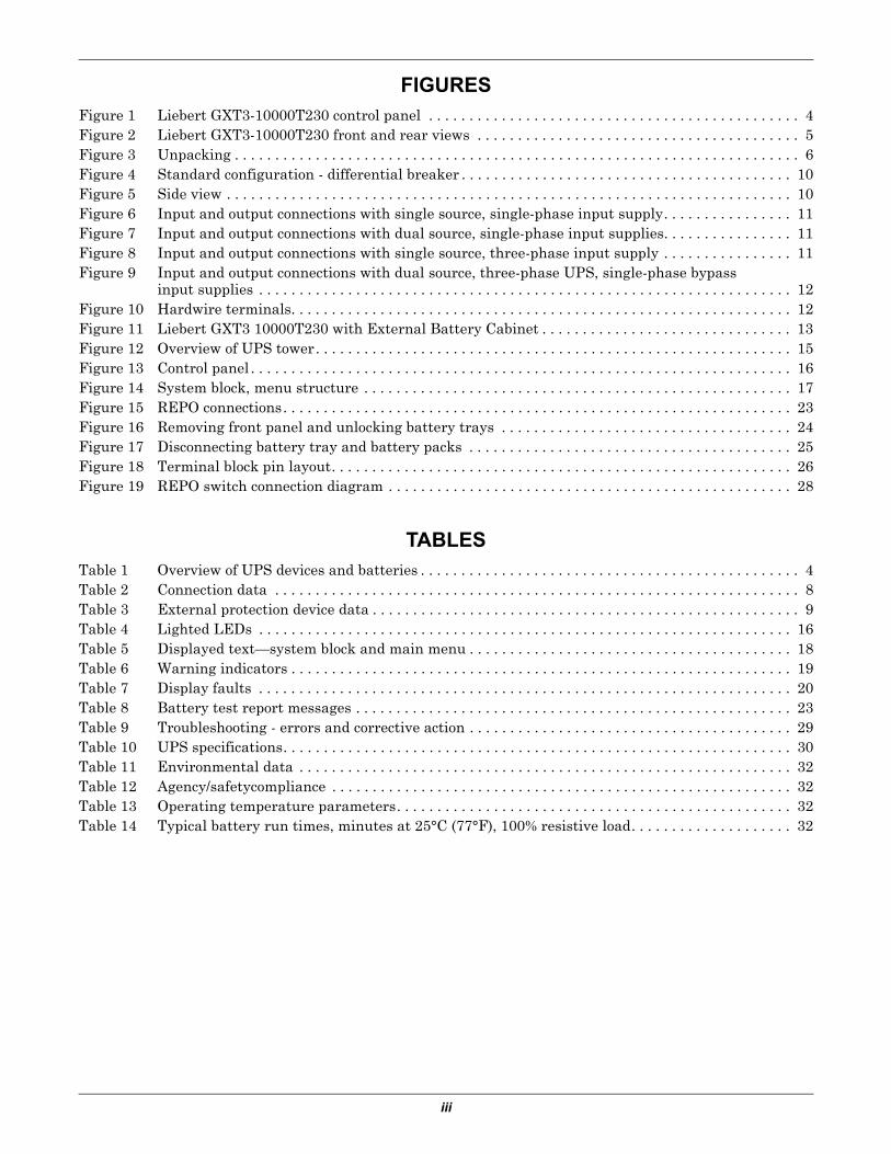
FIGURESFigure 1 Liebert GXT3-10000T230 control panel . . . . . . . . . . . . . . . . . . . . . . . . . . . . . . . . . . . . . . . . . . . . . . 4Figure 2 Liebert GXT3-10000T230 front and rear views . . . . . . . . . . . . . . . . . . . . . . . . . . . . . . . . . . . . . . . . 5Figure 3 Unpacking . . . . . . . . . . . . . . . . . . . . . . . . . . . . . . . . . . . . . . . . . . . . . . . . . . . . . . . . . . . . . . . . . . . . . . 6Figure 4 Standard configuration - differential breaker . . . . . . . . . . . . . . . . . . . . . . . . . . . . . . . . . . . . . . . . . 10Figure 5 Side view . . . . . . . . . . . . . . . . . . . . . . . . . . . . . . . . . . . . . . . . . . . . . . . . . . . . . . . . . . . . . . . . . . . . . . 10Figure 6 Input and output connections with single source, single-phase input supply. . . . . . . . . . . . . . . . 11Figure 7 Input and output connections with dual source, single-phase input supplies. . . . . . . . . . . . . . . . 11Figure 8 Input and output connections with single source, three-phase input supply . . . . . . . . . . . . . . . . 11Figure 9 Input and output connections with dual source, three-phase UPS, single-phase bypass
input supplies . . . . . . . . . . . . . . . . . . . . . . . . . . . . . . . . . . . . . . . . . . . . . . . . . . . . . . . . . . . . . . . . . . 12Figure 10 Hardwire terminals. . . . . . . . . . . . . . . . . . . . . . . . . . . . . . . . . . . . . . . . . . . . . . . . . . . . . . . . . . . . . . 12Figure 11 Liebert GXT3 10000T230 with External Battery Cabinet . . . . . . . . . . . . . . . . . . . . . . . . . . . . . . . 13Figure 12 Overview of UPS tower. . . . . . . . . . . . . . . . . . . . . . . . . . . . . . . . . . . . . . . . . . . . . . . . . . . . . . . . . . . 15Figure 13 Control panel . . . . . . . . . . . . . . . . . . . . . . . . . . . . . . . . . . . . . . . . . . . . . . . . . . . . . . . . . . . . . . . . . . . 16Figure 14 System block, menu structure . . . . . . . . . . . . . . . . . . . . . . . . . . . . . . . . . . . . . . . . . . . . . . . . . . . . . 17Figure 15 REPO connections. . . . . . . . . . . . . . . . . . . . . . . . . . . . . . . . . . . . . . . . . . . . . . . . . . . . . . . . . . . . . . . 23Figure 16 Removing front panel and unlocking battery trays . . . . . . . . . . . . . . . . . . . . . . . . . . . . . . . . . . . . 24Figure 17 Disconnecting battery tray and battery packs . . . . . . . . . . . . . . . . . . . . . . . . . . . . . . . . . . . . . . . . 25Figure 18 Terminal block pin layout. . . . . . . . . . . . . . . . . . . . . . . . . . . . . . . . . . . . . . . . . . . . . . . . . . . . . . . . . 26Figure 19 REPO switch connection diagram . . . . . . . . . . . . . . . . . . . . . . . . . . . . . . . . . . . . . . . . . . . . . . . . . . 28
TABLESTable 1 Overview of UPS devices and batteries . . . . . . . . . . . . . . . . . . . . . . . . . . . . . . . . . . . . . . . . . . . . . . . 4Table 2 Connection data . . . . . . . . . . . . . . . . . . . . . . . . . . . . . . . . . . . . . . . . . . . . . . . . . . . . . . . . . . . . . . . . . 8Table 3 External protection device data . . . . . . . . . . . . . . . . . . . . . . . . . . . . . . . . . . . . . . . . . . . . . . . . . . . . . 9Table 4 Lighted LEDs . . . . . . . . . . . . . . . . . . . . . . . . . . . . . . . . . . . . . . . . . . . . . . . . . . . . . . . . . . . . . . . . . . 16Table 5 Displayed text—system block and main menu . . . . . . . . . . . . . . . . . . . . . . . . . . . . . . . . . . . . . . . . 18Table 6 Warning indicators . . . . . . . . . . . . . . . . . . . . . . . . . . . . . . . . . . . . . . . . . . . . . . . . . . . . . . . . . . . . . . 19Table 7 Display faults . . . . . . . . . . . . . . . . . . . . . . . . . . . . . . . . . . . . . . . . . . . . . . . . . . . . . . . . . . . . . . . . . . 20Table 8 Battery test report messages . . . . . . . . . . . . . . . . . . . . . . . . . . . . . . . . . . . . . . . . . . . . . . . . . . . . . . 23Table 9 Troubleshooting - errors and corrective action . . . . . . . . . . . . . . . . . . . . . . . . . . . . . . . . . . . . . . . . 29Table 10 UPS specifications. . . . . . . . . . . . . . . . . . . . . . . . . . . . . . . . . . . . . . . . . . . . . . . . . . . . . . . . . . . . . . . 30Table 11 Environmental data . . . . . . . . . . . . . . . . . . . . . . . . . . . . . . . . . . . . . . . . . . . . . . . . . . . . . . . . . . . . . 32Table 12 Agency/safetycompliance . . . . . . . . . . . . . . . . . . . . . . . . . . . . . . . . . . . . . . . . . . . . . . . . . . . . . . . . . 32Table 13 Operating temperature parameters. . . . . . . . . . . . . . . . . . . . . . . . . . . . . . . . . . . . . . . . . . . . . . . . . 32Table 14 Typical battery run times, minutes at 25°C (77°F), 100% resistive load. . . . . . . . . . . . . . . . . . . . 32

iv

1
IMPORTANT SAFETY INSTRUCTIONS
SAVE THESE INSTRUCTIONS
This manual contains important safety instructions that must be followed when installing, operating and maintaining the Liebert GXT3-10000T230 uninterruptible power system (UPS).Read all safety, installation and operating instructions before installing or operating the UPS. Adhere to all warnings on the unit and in this manual. Follow all operating and user instructions. The Liebert GXT3-10000T230 is not intended for use with life support or other designated critical devices. The UPS is designed for data processing equipment. If uncertain the intended use for this UPS, consult your dealer or Liebert representative.This device serves as an uninterruptible power supply for connected loads. Maximum load must not exceed that shown on the UPS rating label. The device is in compliance with all relevant safety regu-lations concerning information technology equipment, including electronic machines for use in an office environment.Depending on the type and rating of UPS device, certain configurations of battery extensions may be connected. These battery extensions may be connected only to the compatible basic UPS unit.
! WARNINGOpening or removing the cover may expose you to lethal voltages within this unit even when it is apparently not operating and the input wiring is disconnected from the electrical source. Observe all cautions and warnings in this manual. Failure to do so may result in serious injury or death. Refer all UPS and battery service to qualified service personnel. Do not attempt to service this product yourself. Never work alone.
! WARNINGLiebert considers the safety of personnel to be of paramount importance. For this reason it is essential that procedures relating to safety be studied before commencing work and properly adhered to thereafter.
The user or operator may intervene in the operation of the UPS provided that the instructions laid out in Notes Regarding the EU Declaration of Conformity on page 3 are strictly adhered to.
The installation of the UPS, described in Installation on page 8, may only be carried out by qualified technical personnel.
Even when all switches and interrupters are open, hazardous voltages are present within the UPS; any operation that requires protective panels to be opened or removed may be carried out by Liebert authorized technical personnel only.

2
! CAUTIONCarefully read the following safety notices. Failure to observe the instructions may endanger your life, your health, the reliability of your device and the security of your data.
• Transport the unit only in suitable packaging (protected against jolts and shocks).• If the equipment is moved from a cold environment to the operating room, condensation
may occur. Before you switch On the equipment, it must be absolutely dry. An acclimatiza-tion period of at least two hours is required.
• The equipment must be installed in accordance with the environmental conditions specified in 2.6 - Environmental Conditions and in Table 11 - Environmental data.
• Even with all switches in the “OFF” position (see Figure 13 - Control panel) the UPS is not isolated from the mains. To isolate completely from the mains, the power cables must be disconnected.
• In case of interruption of the mains voltage, the integrated battery maintains the power supply to the user equipment.
• Lay all cables so that nobody can stand on them or trip over them. When connecting the UPS to the power supply, follow the instructions in 2.0 - Unpacking the UPS and Site Preparation.
• Make sure that no objects (e.g., pins, necklaces, paper clips, etc.) get inside the device.• In emergencies (e.g., damaged case, controls or power cables, penetration of liquids or for-
eign matter), switch Off the device and contact the appropriate customer service represen-tative.
• Do not connect equipment that will overload the UPS (e.g., laser printers or vacuum clean-ers) or demand DC-current (e.g., half-wave rectifiers).
• When cleaning the unit, follow the instructions in 5.0 - Maintenance.• The sum of the leakage currents (protective conductor current) of the UPS and the con-
nected devices exceeds 3.5 mA for all ratings of the UPS. Earth connection is essential before connecting supply.
• Data transmission lines should not be connected or disconnected during a thunderstorm.• Remote Emergency Power Off (REPO) input is located on the rear of the unit (see 3.8 - Ter-
minal Blocks for UPS). When this connection is open, the logic circuit will immediately shut down the UPS output.
• An Emergency Switching Device (E.S.D.) must be fitted downstream of the UPS for the wir-ing installation safety to comply with the European Harmonized Document HD384-4-46 S1.
• Maintenance bypass switch is for the use of service personnel only. It is located under the rear cover. Open the safety cover to operate the maintenance bypass switch.
• The Tower UPS may be connected either to 3-phase mains or single-phase mains. Therefore the right input terminals have to be connected (see 3.7 - Connecting Mains and Load). The UPS autosensing mode ensures that it adapts to the connected mains supply.
• This equipment complies with IEC 61000-3-12 provided that the short-circuit ratio Rsce is greater than or equal to 250 at the interface point between the user’s supply and the public system. It is the responsibility of the installer or user of the equipment to ensure, by consul-tation with the distribution network operator if necessary, that the equipment is connected only to a supply with a short-circuit ratio Rsce greater than or equal to 250.
• For three-phase equipment, the disconnect device shall disconnect simultaneously all line conductors of the AC mains supply. For equipment requiring a neutral connection to an IT power distribution system, the disconnect device shall be a four-pole device and shall dis-connect all line conductors and the neutral conductor.
! CAUTIONDo not connect more than four Liebert GXT3-240TBATTCE battery extensions to the Liebert GXT3-10000T230. This also applies when the additional battery charger is connected.
The vents for air intake and outlet at the front and rear side must not be obstructed.
The sum of the leakage currents (protective conductor current) of the UPS and the connected devices exceeds 3.5 mA. Earth connection of the unit is essential before connecting supply.

3
Radio InterferenceThe Liebert GXT3-10000T230 is a Radio Interference Class A Product.
The UPS device may cause radio interference. Do not place it near devices that are particularly sus-ceptible to electromagnetic interference (e.g., transmitters, receivers, radar, metal detectors and anti-theft devices).
NOTICEThis is a product for restricted sales distribution to informed partners. Installation restrictions or additional measures may be needed to prevent radio interference.
Notes Regarding the EU Declaration of ConformityThe Liebert GXT3-10000T230 conforms to the following European directives:
• 2006/95/EC—Directive of the council for adaptation of the legal regulations of the member states regarding electrical equipment for use within specific voltage limits, modified by directive 93/68/EEC.
• 89/336/EEC—Directive of the council for adaptation of the legal regulations of the member states regarding electromagnetic compatibility, modified by directive 2004/108/EC.
Conformity is established through compliance with the following standards:
• EN 62040-1-1• EN 62040-2• EN61000-3-12• EN61000-3-11
Additional information regarding adherence to these directives is included in the appendices NSR and EMC of the EU Declaration of Conformity.
If required, the EU Declaration of Conformity may be requested from Liebert.
NOTICE TO EUROPEAN UNION CUSTOMERS: DISPOSAL OF OLD APPLIANCES—This product has been supplied from an environmentally aware manufacturer that complies with the Waste Electrical and Electronic Equipment (WEEE) Directive 2002/96/CE.
The “crossed-out wheelie bin” symbol at right is placed on this product to encourage recycling wherever possible. Please be environmentally responsible and recycle this product through your recycling facility at its end of life. Do not dispose of this product as unsorted municipal waste. Follow local munici-pal waste ordinances for proper disposal provisions to reduce the environmen-tal impact of waste electrical and electronic equipment (WEEE).
For information regarding the scrapping of this equipment, go to
http://www.eu.emersonnetworkpower.comClick on Products or Contacts and follow the links to obtain assistance.
Information is also available by telephoning our worldwide technical support:
• Toll free: 00 80011554499• Toll number (in Italy): +39 0298250222
! CAUTIONThe supply to the load may be interrupted by opening all the switches or by turning the Maintenance Switch on the rear of the UPS to the Off position.
DO NOT USE WATER to extinguish any fires that may occur in the area where the UPS is installed.
! CAUTIONLeakage currents
Connect the protection earth (PE) safety conductor before connecting any other cables.

Introduction and System Description
4
1.0 INTRODUCTION AND SYSTEM DESCRIPTION
Congratulations on your purchase of the Liebert GXT3-10000T230. This system provides conditioned power to microcomputers and other sensitive electronic equipment.
Upon generation, AC power is clean and stable. However, during transmission and distribution it is subject to voltage sags, spikes and complete power failure that may interrupt computer operations, cause data loss and damage equipment. The Liebert GXT3-10000T230 protects equipment from these disturbances.
The Liebert GXT3-10000T230 is a compact, on-line UPS. An on-line UPS continuously conditions and regulates its output voltage whether utility power is present or not. It supplies connected equipment with clean sinewave power. Sensitive electronic equipment operates best from sinewave power.
For ease of use, the Liebert GXT3-10000T230 features an LCD display for comprehensive user indica-tions and programmable controls. It also provides self-diagnostic tests.
The Liebert GXT3-10000T230 has an interface port for communication between the UPS and a net-work server or other computer system. This port provides detailed operating information including voltages, currents and alarm status to the host system when used in conjunction with Liebert’s Mul-tiLink™ software.
Figure 1 Liebert GXT3-10000T230 control panel
1.1 Device OverviewThe Liebert GXT3-10000T230 is available at various nominal power ratings.
The following table provides an overview of the various versions of the device:
! CAUTIONThis UPS may only be operated by qualified personnel.
Table 1 Overview of UPS devices and batteriesType Model # Nominal powerUPS with integrated battery Liebert GXT3-10000T230 10000 VA/ 9000W
Battery cabinet Liebert GXT3-240TBATTCE 240VDC

Introduction and System Description
5
Figure 2 Liebert GXT3-10000T230 front and rear views
1.2 Options
1.2.1 External Battery CabinetsOptional external battery cabinets are available to extend UPS autonomy in the event of mains inter-ruption. The cabinets have the same dimensions, color scheme and design as the Liebert GXT3-10000T230.
For technical data about external battery cabinets see Table 10 - UPS specifications.
For connection notices see Table 2 - Connection data.
1.2.2 Optional InterfacesRefer to 6.0 - Communication for details.
Control Panel
Control Keys
Liquid Crystal Display
Ventilation Louvers
Liebert IntelliSlotport (covered)
REPO Contacts
Maintenance Bypass Switch
Parallel Port
Parallel Port
Bypass Source Input Circuit Breaker
Input Breaker
Hardwire Input and OutputConnectorTerminal Block
Cooling Fans
ExternalBatteryConnector Block
Output Breaker

Unpacking the UPS and Site Preparation
6
2.0 UNPACKING THE UPS AND SITE PREPARATION
2.1 InspectionUpon receiving your Liebert GXT3-10000T230, examine the packaging for any signs of mishandling or damage. While removing the packaging materials, inspect the UPS for damage. If any damage is noted, notify your local Liebert representative and carrier. Any damage or missing parts must be reported to the supplier within eight days of delivery.
2.2 Required Setup EquipmentThe following tools are required to set up your UPS:
• pallet jack• utility knife or scissors• star head screwdriver
2.3 UnpackingTake care when removing the packaging to avoid damaging the UPS. Do not dispose of the packing material. The original packaging material should be used if the UPS needs to be repackaged, such as for shipping. Check all packaging to ensure that no items are accidentally discarded. Remove the packaging in the sequence shown below.
Figure 3 Unpacking
2.4 StorageIf the UPS will not be installed immediately, store the unit indoors in a clean and dry area. Protect all the equipment, including its batteries, from extreme temperature, high humidity, spills and other damaging conditions. Refer to Table 11 for permissible environmental conditions for storage.
2.5 HandlingThe equipment must be kept upright at all times and handled with care. It may be damaged if dropped or subjected to severe impact.
Unlock
Plywood Case
Ramp in Slot on Shipping Pallet
Cushion
Ramp
Cushion
Pallet JackCushions

Unpacking the UPS and Site Preparation
7
2.6 Environmental ConditionsThe Liebert GXT3-10000T230 must be installed vertically, on a level and even surface and in an area protected from extreme temperatures, water, humidity and the presence of conductive powder or dust (see Table 11). Do not stack units; do not place any objects on top of a unit.
2.7 Access requiredThe area must have sufficient space for installation procedures and for routine maintenance. Access doors must be sufficiently large to permit passage of the UPS.
2.8 Floor/Rack LoadingEnsure that the floor where the UPS/batteries will be installed will support the unit’s weight (see Table 10 for the unit’s weight).
2.9 Inventory ListThe Liebert GXT3-10000T230 comes with:
• CD containing:• Liebert MultiLink® Shutdown Software• Configuration Software• User Manual
• USB cable• Terminal block communication terminals• Floor mount brackets• Input power configuration jumpers• Paralleling cable
2.10 ClearanceThe UPS is fitted with wheels for ease of movement over short distances. Leave 300mm (12in.) around the sides and rear of the unit to allow a flow of air and to provide access for any routine main-tenance that may involve removal of the panels.
2.11 Repacking the UPSTo repack the UPS, proceed as follows:
1. Do not pack the equipment until at least six hours have elapsed since the last recharge.2. Make sure to re-use the original packing material to ship the UPS.

Installation
8
3.0 INSTALLATION
3.1 Electrical preparationsBefore you begin installation, the input source must be isolated and secured to prevent reconnection during installation. The input circuit breaker on the rear of the UPS must be in the Off position.
For electrical installation, the nominal current rating of the source must be observed. The UPS is not suitable for connection to 16A subdistribution systems.
3.2 Current Table and Suggested Cable SizesThe following table indicates the currents and recommended sizes of the connecting cables in accor-dance with regulations IEC-287 and DIN VDE 0298
1. PVC-insulated copper cables (@ 70°C) (158°F).2. Air temperature surrounding the conduits should not be greater than 30°C (86°F).
When the UPS is in Bypass mode, the entire output current of the UPS is passed through the phase L1 and Neutral cables. To simplify connection data, no distinction has been made between phase L1 and phases L2 and L3. The cable sizes are defined for the maximum current carried by the output cables.
! WARNINGInstallation may be carried out only by qualified technicians, conforming to applicable safety standards.
Electric shock hazard: Even when the unit is disconnected from the mains, hazardous voltage may still be supplied by the battery. Both poles should be disconnected before carrying out maintenance work inside the UPS.
NOTEShould there be any variation in the conditions, it will be necessary to verify whether the cable dimensions satisfy the requirements of IEC-287 and DIN VDE 0298. In cases where the cables are so long that they cause a drop in voltage of >3%, a larger size must be used.
Table 2 Connection data
DescriptionUnit UPS Power Rating
kVA 10 - 1/1 10 - 3/1
Connector size mm2 10 10
Max input current Arms 53 53
Input cable size(and neutral) mm2 10 10
Max output current Arms 51 51
Output cable size(and neutral) mm2 10 10
Earth cable size mm2 10 10
! WARNINGParticularly sensitive equipment may be susceptible to interference. To prevent this, Liebert suggests:
Mains input, output and external battery cables to the UPS in earthed, metal conduits, or
Use shielded cables
Routing of cables (e.g. power supplies, communication or data lines) to other equipment, should be kept separate from that of UPS cables.

Installation
9
3.3 Neutral ConnectionThe installation of the UPS does not affect the existing neutral system.
The neutral system may be affected if the UPS is operating with the neutral switched upstream.
3.4 External Protection and Isolating DevicesExternal devices for the protection of cables and for isolating the UPS external to the UPS must be installed upstream of the equipment. Select and configure the isolating device according to Table 3.
• Such devices must be either curve C automatic circuit breakers or type GL/GG fuses.• Disconnecting devices must be provided in building installations and other locations.
This table indicates the protection devices (circuit breakers and fuses) that must be installed for the protection of both the cables and the equipment.
! WARNINGThe following label must be displayed on all switching devices installed in the same electrical system as the UPS, even when they are located at a distance from the area.
ENSURE THAT THE UNINTERRUPTIBLE POWER SYSTEM IS ISOLATED BEFORE WORKING ON THIS CIRCUIT.
Table 3 External protection device data
Protection Description
Tower Power Rating (Phases In/Out)
10 - (1/1) 10 - (3/1)
InputFuse 120 Amps 40 Amps
Breaker 96 Amps 32 Amps
OutputFuse 90 Amps 90 Amps
Breaker 63 Amps 63 Amps
NOTEIf an external battery cabinet is present it should be located next to the UPS unit.
When such an option is supplied by Liebert it comes complete with protection devices and correctly-sized cables.
When batteries are sourced from other suppliers, you should contact Customer Support Technical Service for correct sizing of protection devices and interconnection cables.
Installation
10
3.5 Installation of Differential Protection DevicesTo avoid spurious operation, differential protection devices must be:
• rated at differential current NOT LESS THAN 100mA• a SELECTIVE type (delayed intervention)• Type A
Figure 4 Standard configuration - differential breaker
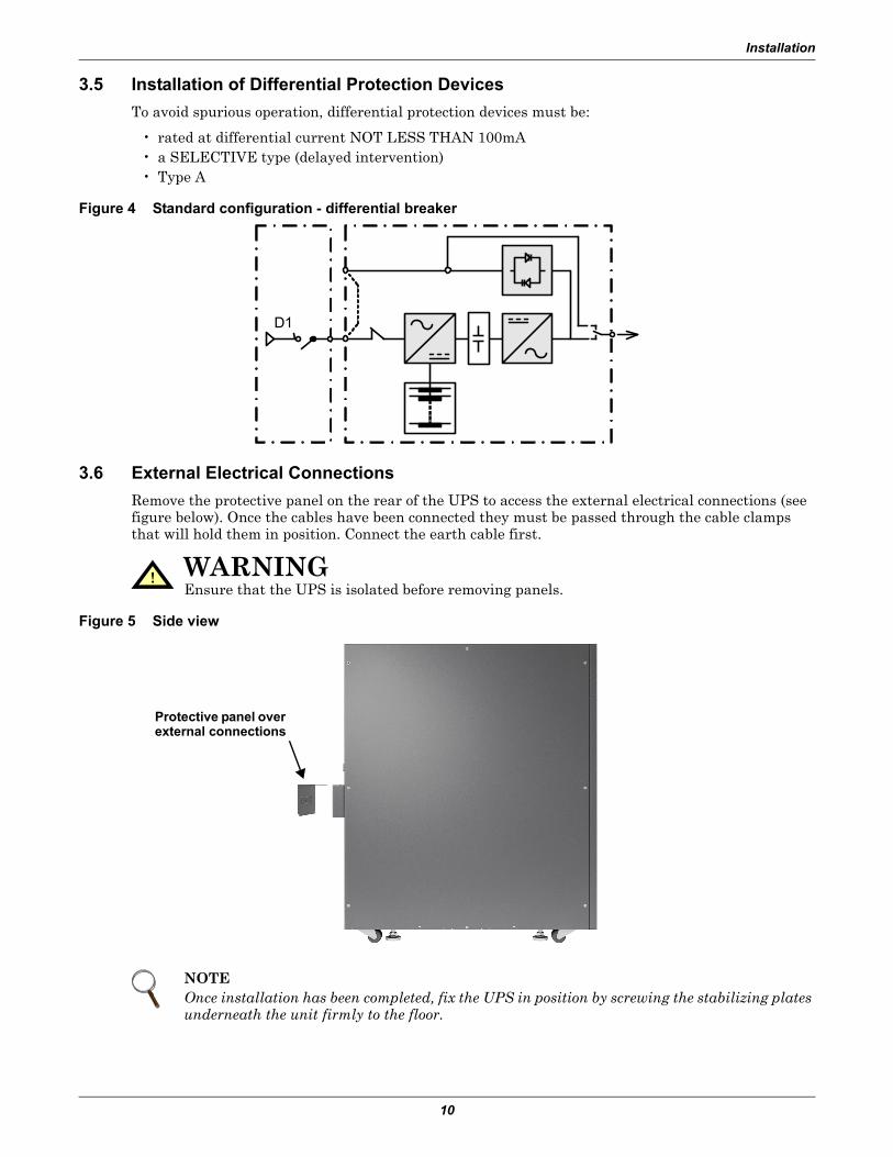
3.6 External Electrical ConnectionsRemove the protective panel on the rear of the UPS to access the external electrical connections (see figure below). Once the cables have been connected they must be passed through the cable clamps that will hold them in position. Connect the earth cable first.
Figure 5 Side view
! WARNINGEnsure that the UPS is isolated before removing panels.
NOTEOnce installation has been completed, fix the UPS in position by screwing the stabilizing plates underneath the unit firmly to the floor.
D1
Protective panel over external connections

Installation
11
3.7 Connecting Mains and LoadWhen connect the mains supply to the UPS refer to Figures 6 through 8. Choose the connection method according to the input supply characteristics. Connections must meet these requirements:
• The installer must provide circuit breaker protection according to local codes. The mains discon-nect should be within sight of the UPS or have an appropriate lock-out. Maintain service space around the UPS or use flexible conduit.
• The installer must provide output distribution panels, circuit breaker protection, or emergency disconnect switches according to local codes. Output circuits must not share a common conduit with input circuits or any other wiring.
• The utility may be derived from a single-phase or three-phase source.
Figure 6 Input and output connections with single source, single-phase input supply
Figure 7 Input and output connections with dual source, single-phase input supplies
Figure 8 Input and output connections with single source, three-phase input supply
Mains 1 Input ~ Mains 2 Input ~ Output ~
L1 L2 GND BY
230V Input
L3 N
ParallelConnection
N GND L S1 S2N GNDL1
Factory-Supplied Jumper (W36) 230V
230V UPS Input 230V 230V Bypass Input
Mains 1 Input ~ Mains 2 Input ~ Output ~
L1 L2 GND BYL3 N
ParallelConnection
N GND L S1 S2N GNDL1
Factory-Supplied Jumper (W35)
Factory-Supplied Jumper (W34)
400V Input 230V
Mains 1 Input ~ Mains 2 Input ~ Output ~
L1 L2 GND BYL3 N
ParallelConnection
N GND L S1 S2N GNDL1

Installation
12
Figure 9 Input and output connections with dual source, three-phase UPS, single-phase bypass input supplies
3.8 Terminal Blocks for UPSThe three-position maintenance switch includes the output breaker.
Figure 10 Hardwire terminals
3.9 Connecting Power Cables1. Open the UPS input breaker.2. Open the UPS output breaker.3. Remove the terminal area safety cover from the rear UPS panel.4. Connect loads to the output terminals.
• Connect the mains to the corresponding input terminals (see Figure 3-5).• If the reserve input is to be supplied separately, connect reserve line to the Mains 2 terminals.• If the UPS is supplied by a common mains, connect the supplied jumper in the accessory kit
marked “W34” between the first L1 from the left (Mains 1) and BY (Mains 2) as shown in Figure 8.
NOTEDuring connection of a 3-phase input system, care must be taken to ensure each phase is connected to the corresponding phase on the input terminal block. Failure to make connections correctly could damage the unit.
Output cable cannot exceed 10m (39ft).
400V Input 230V
Mains 1 Input ~ Mains 2 Input ~ Output ~
L1 L2 GND BYL3 N
ParallelConnection
N GND L S1 S2N GNDL1
230V Bypass Input
Reserved for future use

Installation
13
3.10 External Tower BatteriesOne or more battery cabinets may be connected to the Liebert GXT3-10000T230. A cable to connect the battery cabinet and the Liebert GXT3-10000T230 is supplied with each battery cabinet. Plug this cable into the battery cabinet and UPS battery sockets—slotted fittings on each and ensure that the connection is properly made. If your UPS has an integrated battery, a compensating current may occur during connection.
Figure 11 Liebert GXT3 10000T230 with External Battery Cabinet
3.11 Connecting an External Battery Extension
The unit checks the battery voltage (a beep is heard) once more and stays in bypass till a constant battery voltage is present.
NOTEExternal battery extensions can be replaced during normal operation of the UPS (hot swappable). However, the batteries must NOT be changed when the UPS is in the status “Battery Mode operation”.
! CAUTIONBattery maintenance must be carried out by authorized personnel observing the necessary precautions.

Installation
14
3.12 Battery Precautions• The batteries installed in the UPS and within the battery extensions may contain electrolyte.
Under normal conditions, the containers are dry. A damaged battery may leak electrolyte, which can cause skin and eye irritation. Should this happen, wash the affected area with plenty of water and seek immediate medical attention.
• Do not open or damage batteries. The released electrolyte is toxic.• Voltage is always present on the battery contacts.• Even when discharged, a battery has the capacity a high short circuit current which, in addition
to causing damage to the battery itself and associated cables, may expose the operator to the risk of burns. The following precautions should be observed when working with batteries:
• Remove watches, rings and other metal objects.• Use tools with insulated handles.• The voltage of a single cell of a battery is not dangerous. However a number of cells or battery
blocks, connected in series, can produce hazardous voltages.• The battery cabinet must not be kept in storage or not used for periods exceeding six months (at
20°C) without being recharged (having been charged to 100% at the beginning of any such period). If this period is exceeded, it is essential that the batteries be recharged (which requires the UPS to be switched On). If these conditions are not met, the battery performance can no longer be guaranteed. We recommend recharging the batteries at least once every four months.
• Since new batteries often do not provide full capacity after the initial charge, it may be necessary to carry out a number of discharge/recharge cycles before optimum performance is reached.
• When replacing batteries, replace with the same type and number of batteries and battery packs.• In order to protect the environment, batteries must be disposed of in accordance with local laws
concerning the safe disposal of toxic and harmful waste.• Do no not dispose of batteries in a fire. The batteries may explode.
3.13 Configuration ProgramThe final step of installation may require custom configuration of your UPS using the enclosed config-uration program. Some configuration settings may be changed only while the UPS is Off. These should be set before the UPS is put into full-time use.
For most users operating with 230VAC, the factory default settings will be adequate.
3.14 Liebert GXT3-10000T230 Configuration Program Features• Select one of the three L-N output voltages to match local voltage.• Enable/disable auto-restart.• Select frequency converter operation with a fixed output frequency of 50 or 60 Hz.• Set the ‘Low battery warning’ alarm time from 2 to 30 minutes.• Enable/disable auto-battery test.• Set auto-battery test frequency to 7, 14, 21 or 28 days.• Specify the number of external battery cabinets connected to the UPS to adjust the remaining run
time calculations reported by the system software.
3.15 What You Will NeedIn addition to the Liebert GXT3-10000T230, you will need the configuration program CD and USB cable included in the UPS accessory pack. You must be running Microsoft® Windows® XP or later on your computer.

Operation
15
4.0 OPERATION
4.1 Normal Operating
4.1.1 Block diagramThe Liebert GXT3-10000T230 consists of several main components:
• 2 mains supplies (mains and reserve)• Rectifier/booster, inverter and charger• Internal electronic bypass• 2 input breakers• Maintenance bypass breaker• TVSS filter• Integrated battery (expandable)
Figure 12 Overview of UPS tower
L2,L3 at 10kVA device only
Rectifier/Booster
Inverter
Electronic Bypass
Maintenance BypassMaintenance
Bypass Switch
Mai
ns1
Mai
ns2
(Res
erve
)
N
N
By
L1L2L3
N
N
L
L
Load
S2S1
External Battery 10kVA Tower

Operation
16
4.2 Control PanelThe display text is shown as a 10kVA UPS.
Figure 13 Control panel
4.2.1 Controls and Messages
Flashing LED—When the BYPASS LED is flashing, the mains is out of tolerance
The following displays the menu structure that can be accessed through the control panel. Press the Menu Up or Menu Down buttons to scroll through each menu. Press Enter to choose an entry.
Table 4 Lighted LEDsLED Indicator LED Color DescriptionUPS ON Green UPS is online and operating normally
BYPASS Amber Load is supplied by the mains via automatic bypass
BATTERY Amber Load is supplied by the battery
FAULT Red An error has occurred within the UPS
! CAUTIONDo not switch Off the UPS or switch from online to bypass while in this status, otherwise load will no longer be supported.
LCD
Enter key
Menu Up keyMenu Down key
Escapekey
Battery IndicatorFault Indicator
BypassIndicator
UPS Output On Indicator

Operation
17
Figure 14 System block, menu structure
Start Window
System Status
MainMenu
SetupMenu
StatusMenu
Parallel Menu
Language
Tag Number
UPS IDNo.
DC Start
Test Intvl
BattPack
Audible Alarm
OutputVolt
No. of Unit
ControlMenu
Contrast
Batt Test
Alarm Ctrl
UPSON/OFF
TestReport
Abort Test
Batt Test
Version
IP
Types
AboutMenu
LogMenu
ClearLog
Event Log

Operation
18
Table 5 Displayed text—system block and main menuItem# and Name Description
START WINDOW UPS 10kVA Self Testing
MAIN MENU
Control
Status
Parallel
Setup
Log
About
CONTROL MENU
UPS ON/OFF Turn On
Shut Down
Turn Off
To Bypass
Alarm Ctrl Alarm On
Alarm Off
Batt Test Batt Test
Abort Test
Test Report
Contrast Darker
Lighter
STATUS MENU
Measure Value Unit
Output Volt V
Output Freq 0.1Hz
Output Curr A
Output Watt W
Output VA VA
Load Level %
Input Volt V
L2 Input Volt V
L3 Input Volt V
Input Freq 0.1Hz
Batt Volt V
Batt Cap %
Backup Time Min,sec
Elapsed Time day:hr:min;sec
Tag Number
PARALLELMENU
SysOutI A
SysOutV V
SysOutF Hz
SysOutW W
SysOutVA VA
SysLoadPer %

Operation
19
4.2.2 Warning IndicatorsIf a warning indicator appears, the UPS continues to operate. The warning message alternates with UPS mode once a second (see Table 6)The warning indicators are described below:
SETUP MENU Setting item Setting(level 1)
Audible Alarm Disable/Enable
Output Volt 220V/230V/240V
Batt Pack 1-4
Test intvl
DC Start Disable/Enable
UPS ID No. 1-3
No. of Unit 1-3
Tag Number 00000-99999
Language English/French/Spanish/German/Italian/Russian
LOGGING MENU
Event log
Clear log
* Max 4 fault event record
FIRMWARE VERSION
Types Liebert Corporation GXT 10KVA Liebert GXT3 10kVA
IP Web:www.liebert.com www.liebert.com
Version Display Firmware version MCU Version:V***DSP Version: V***
Table 6 Warning indicatorsWarning Cause Corrective Steps
1 No Redundancy2 InvASynFault3 ParaCommuErr4 CurShareFault5 ParaFreqErr6 Byp Reminder7 L2 or L# Fail Check L2, L3 input fuse8 UtilFail N/A9 BattUnderVolt N/A
Table 5 Displayed text—system block and main menuItem# and Name Description

Operation
20
4.2.3 Fault IndicatorsIf a fault occurs, the UPS automatically switches to BYPASS mode. Only in the case of a battery dis-connection fault will the original operating mode be maintained. The fault message alternates with UPS mode once a second, the red fault LED on the control panel lights up and the alarm sounds con-tinuously. If a fault occurs, proceed as follows:Alarm operation—The alarm can be switched On or Off.Clear Fault—Present fault condition can be reset if fault condition is cleared, either automatically or by the user.Fault information—A maximum of four faults can be displayed in this window. All fault displays include:
• The nature of the event• The time of the event
The fault indicators are:
4.3 Startup PreparationsBefore switching On the UPS and supplying the load, ensure the following:
• The ventilation grilles are unobstructed• The earth connection is in place• The ‘consumer’ breakers are in the Off (0) position• The UPS rear panel breakers are in the Off (0) position
Once recharging has been completed, the UPS is ready for use.
Table 7 Display faultsFault Cause Corrective Steps
1 Comm Shutdown Call customer service2 Inv Fault Call customer service3 Over Temp Reduce load4 Batt Test Fail Call customer service5 PFC Failure Call customer service6 Over load Reduce load7 DCDC Failure Call customer service8 DC BUS Fault Call customer service9 Charger Fault Call customer service10 REPO N/A11 Byp Feedback Call customer service12 Startup No Batt Check battery13 Mnt Byo Swt On Call customer service14 Fan Fault Call customer service15 Batt Disconnect Check battery connector16 ParaCableFault Call customer service17 ParaAddOverlap Call customer service18 Turn On Fail Call customer service
! WARNINGAs soon as the UPS is connected to input power, the output sockets are live, even if the UPS is not yet switched On.
! WARNINGDo not connect any devices that may overload the UPS or draw DC current.
NOTEYou may experience problems with the electrical supply if you do not follow these instructions.

Operation
21
4.4 UPS Startup Procedure - Single Block1. Ensure all switches and circuit breakers upstream of the UPS are closed.2. Ensure mains connections are secured at the UPS input. UPS requires twin supplies or one
supply and one bridge. If the UPS is supplied from one mains only, mains connectors have to be fixed to the terminals section Mains 1. The jumper must be fixed as:
From L1 - mains 1 to BY - mains 23. Switch both Input breakers (mains 1 and mains 2/reserve) to ON (I). The LCD displays Self
testing, Please wait (see 4.2.1 - Controls and Messages).4. Press OK and scroll to find the Setup menu.5. Check and adjust if necessary parameters for language, voltage and battery pack(s) (see Table 5
for more information). The default language is English.6. Close any external switches connecting the load (if present).7. Press the Menu button, select Control and press OK.8. Select Turn UPS ON/OFF and press OK. The LCD will display Turn ON.9. Press OK to switch On the inverter. The LCD will display Powering UP.
4.5 UPS Shutdown Procedure—All Ratings
1. Press the Menu button, select Control and press OK.2. Select UPS ON/OFF and press OK.
The LCD displays To Bypass.3. Press OK to switch Off the inverter.4. Open any external switches connecting the load (if present).5. Switch both input switches to the Off Position.6. Ensure all switches and circuit breakers upstream of the UPS are open.7. Ensure that all LEDs on the control panel are Off.
The UPS is now shut down.
4.6 Maintenance Bypass Procedure1. Press the Menu button, select Control and press OK.2. Select UPS ON/OFF and press OK.
The LCD displays To BYPASS.3. Press OK to switch Off the inverter and transfer to internal bypass.4. Remove the safety cover from the Maintenance switch, and turn On the Maintenance Bypass
Breaker.
5. Switch output and input switches to the Off position.6. The UPS is now switched Off, all LEDs are Off and the load is supplied directly from the mains.
! WARNINGIf the load indication is greater than 100%, then the energy demand from the connected load exceeds the power rating of the UPS. In addition to a warning being displayed on the front panel, a beep (once a second) will sound.
NOTECarrying out this procedure will interrupt the supply to load.
NOTEAt this point, the load is no longer protected against interruptions and disturbances of the mains.

Operation
22
4.7 Return from Maintenance Bypass Procedure1. Ensure all switches and circuit breakers upstream of the UPS are closed.2. Switch both input switches to the On position.3. Wait at least 30 seconds until the output voltage has stabilized (the yellow LED is lit). 4. Switch the Maintenance switch from BYPASS to UPS and replace the cover. The load is now
supplied via internal bypass. 5. Press the Menu button, select Control and press OK.6. Select UPS ON/OFF and press OK.
The LCD displays UPS to ON.7. Press OK to switch On the inverter.
4.8 Functional Test
The Liebert GXT3-10000T230’s controls permit testing the UPS to ensure that the load will be sup-plied in the event of a mains failure.
Before beginning, ensure that the batteries are fully charged.
Simulate a mains failure by interrupting the mains supply to the UPS. You can do this by switching Off the input power circuit breaker on the rear panel of the UPS. If the mains supply to the Liebert GXT3-10000T230 is protected by an external circuit breaker, opening that circuit breaker will inter-rupt the mains supply and simulate a power failure.
The Liebert GXT3-10000T230 is operating properly and the batteries are charged if:
• An audible signal is heard at four-second intervals • The UPS On LED indicator turns Off
When the interval between the audible signals decreases to 10 seconds, the UPS has battery reserve energy to supply the load for a maximum of two more minutes. After two minutes, the Liebert GXT3-10000T230 will automatically shut down.
If the batteries do not supply the load during the simulation, refer to 7.0 - Troubleshooting. To end the simulated mains failure, restore the input power supply to the UPS. The UPS is now ready for operation.
4.9 Remote Emergency Power OffThe UPS is equipped with an Emergency Power Off circuit. A factory-installed jumper allows the UPS to operate without an external shutoff switch.
If a Remote Emergency Power Off switch is required, a switch with normally closed contacts must be used.
Connect the switch contacts to the UPS by removing the factory-installed jumper as shown in Figure 15.
NOTESupply to the load is not guaranteed during this test. The test should not be carried out if a critical load is connected to the UPS.
NOTEThe batteries must be recharged before the complete emergency supply period is again available.

Operation
23
Figure 15 REPO connections
4.10 Self-Tests
4.10.1 Lamp Test
1. With the Liebert GXT3-10000T230 connected to the mains, press the Menu button, select Control and press OK.Select UPS ON/OFF and press OK.The LCD will show To BYPASS.
2. Press OK to switch the inverter to Bypass mode.A system confirmation beep will sound.
4.10.2 Battery Test
1. Press the Menu button.2. Select Control and press OK.3. Select BATT TEST and press OK.
A system confirmation beep will sound and the load will be supplied by the battery.
If the test is successful, the BATT LED will turn off, and the UPS will return to Line mode. If the UPS circuitry detects a battery malfunction, the system will display an alarm (see 4.2.1 - Controls and Messages)
See Table 8 for battery test report messages:
NOTEThis test involves putting the Liebert GXT3-10000T230 into bypass mode. The load is not protected against any mains disturbance or interruptions while the UPS is in bypass mode.
NOTEDuring the test a beep will sound as though the device is operating in battery mode.
Table 8 Battery test report messagesMenu entry Display
Battery test report
In Progress
Test OK!
Test fail

Maintenance
24
5.0 MAINTENANCE
5.1 Testing, Replacing and Disposing of BatteriesThe UPS does not require maintenance by the user. When the batteries expire, they must be replaced by the appropriate customer service representative. For servicing, replace batteries with the same type and number of batteries or battery packs that were installed at the factory. For the battery type, see Table 10.
Disposal of the UPS and batteries should be carried out by a certified disposal company - observe all local regulations and laws. Exhausted accumulator batteries are classified as harmful toxic waste and as such the law demands that they be disposed of by an authorized recycling centre.
The Liebert power protection customer service centre is fully equipped to deal with such batteries, in accordance with the law and with the greatest respect for the environment.
The typical battery life cycle is three to five years, at an ambient temperature of 77°F (25°C), but is also dependent on the frequency and duration of mains failures.
The battery test (see 4.10.2 - Battery Test) should be run periodically (every 6 to 12 months) to ascertain the general condition of the batteries and to ensure maximum run time.
5.2 Easy Battery ReplacementOpen the front panel as shown below. Ensure that a certified service engineer is present to replace the batteries.
1. Open the battery tray DC connectors as shown2. Remove the battery trays from the cabinet3. Replace the old batteries with a new set. Replacement batteries must be the same type installed
at the factory4. Reconnect the battery cables
Figure 16 Removing front panel and unlocking battery trays

Maintenance
25
Figure 17 Disconnecting battery tray and battery packs
5.3 StorageFor extended storage at ambient temperatures cooler that 25°C (77°F), the batteries should be charged for five hours once every four months. At higher storage temperatures. Liebert recommends charging batteries for five hours every two months.
After five hours, disconnect from the mains supply or switch Off the input miniature circuit breaker of the UPS. Then remove the UPS connections in the opposite sequence to that described in 3.0 - Instal-lation.
Record the battery charging date in the vicinity of the UPS, for example, on its packaging.
5.4 Cleaning1. Do not clean the UPS with scouring powder or solutions that may dissolve plastic.2. Do not allow liquid to get inside the UPS.3. Make sure that the air vents on the UPS are not obstructed. Remove dust from the air vents with
a vacuum cleaner.4. Clean the outside of the UPS by wiping the housing with a dry or slightly damp cloth.
DC connectors

Communication
26
6.0 COMMUNICATION
6.1 Communication Interface PortThe Liebert GXT3 UPS has a terminal block on the rear of the UPS unit. Several signals are provided on this port and are assigned as follows.
6.2 Terminal BlockThe terminal block includes eight pins in four sets, as shown in Figure 18.
Figure 18 Terminal block pin layout
6.2.1 Any Mode ShutdownThe purpose of Any Mode Shutdown is to shut down the UPS output by turning Off the rectifier, inverter and static switch so that there is no power to the loads.
Any Mode Shutdown can be operated locally or remotely:
• Local Any Mode Shutdown can be performed by shorting the pins in Set 3.• Remote Any Mode Shutdown can be performed using a switch connected to the pins in Set 3 and
mounted at a remote location.
Activation of the Any Mode Shutdown will be logged as an event in the event history log.
NOTERemote Power Off will be performed either by NO or NC contact of Any Mode Shutdown.The current limited source (+12VDC, 50mA) will be available from UPS.The connection to UPS for remote connection will be via terminal block connector.Any Mode Shutdown wiring must conform to all national, regional and local wiring codes and laws.
! WARNINGWhen the Auto-enable output option is selected and the UPS output is disabled using the pins in Set 3, the Liebert GXT3’s output can turn On automatically and without warning if the connection to the pins in Set 3 is changed.
1 2 3 4Low Battery
WarningOn-Battery
WarningAny Mode Shutdown
Battery Mode Shutdown

Communication
27
6.2.2 Battery Mode ShutdownBattery Mode Shutdown permits shutting down the UPS by turning Off the rectifier, inverter and static switch so that there is no power to the load when the UPS is On Battery. The auxiliary power for the UPS will still be active.
Battery Mode Shutdown can be performed locally or remotely:
• Local Battery Mode shutdown can be performed by shorting the pins in Set 4.• Remote Battery Mode Shutdown can be performed using a switch connected to the pins in Set 4
and mounted at remote location.
Activation of the Battery Mode Shutdown will be logged as an event in the event history log.
6.2.3 On BatteryOn Battery signal is a Normally Open (NO) dry contact. When the UPS is supplying output power from the battery this dry contact will be closed.
6.2.4 Low BatteryLow Battery signal is a Normally Open (NO) dry contact. When the UPS is supplying output power from the battery and has reached the Low Battery Warning time selected in the configuration pro-gram, this dry contact will be closed.
6.3 UPS IntelliSlot Communication CardsThe Liebert IntelliSlot port accepts three optional cards:
• Liebert IntelliSlot SNMP Card• Liebert IntelliSlot Relay Card• Liebert IntelliSlot 485 Card.
The Liebert IntelliSlot SNMP Card provides SNMP monitoring and control of the UPS across the net-work.
The Liebert IntelliSlot Relay Card provides dry contact relay outputs for custom-wired applications and delivers support for built-in shutdown for AS/400 systems.
The Liebert IntelliSlot 485 Card is used to connect the UPS and computer system.
Follow instructions provided with the Liebert IntelliSlot card to configure Liebert MultiLink, the UPS or any additional ancillary product for the Liebert GXT3. These instructions are available at
multilink.liebert.com
NOTERemote Power Off will be performed by NO contact.
The current limited source (+12VDC, 50mA) will be available from UPS.
The connection to the Liebert GXT3 for remote connection will be via terminal block connector.
Battery Mode Shutdown wiring must conform to all national, regional and local wiring codes and laws.
This signal must last for 1.5 seconds or longer.
A battery shutdown signal will not cause an immediate shutdown. It will start a 2-minute shutdown timer. This timer cannot be stopped once triggered. If the utility power returns during this countdown, the Liebert GXT3 will still shut down and must remain shut down for 10 seconds. Whether the UPS turns back On when the power is restored depends on the auto-restart setting.
NOTEThe rated values for the dry contacts are:
• Rated Voltage: 5V• Working Voltage Range: 4.5-10V• Rated Current: 30ma

Communication
28
6.3.1 Liebert MultiLinkLiebert MultiLink continually monitors the UPS and can shut down your computer or server in the event of an extended power failure.
Liebert MultiLink can also be configured for use without the USB cable when the Liebert IntelliSlot SNMP/Web card is installed in the UPS. Additionally, Liebert MultiLink can be configured to coordi-nate shutdown across the network with other computers running Liebert MultiLink when you pur-chase a Liebert MultiLink License Kit. For more information about the Liebert IntelliSlot SNMP/Web Card and Liebert MultiLink License Kits, visit our Web site (www.liebert.com) or contact your local dealer or Emerson representative.
Several option cards are available for use in the Liebert IntelliSlot port of the Liebert GXT3. The Lie-bert IntelliSlot SNMP/Web Card provides SNMP and Web-based monitoring and control of the UPS across the network.
The Liebert IntelliSlot MultiPort 4 Card allows installing Liebert MultiLink software on four comput-ers and coordinate shutdown in the event of a power failure.
The Liebert IntelliSlot Relay Card provides dry contact relay outputs for custom wired applications and delivers support for built-in shutdown for AS/400 systems.
6.4 Remote Emergency Power OffThe UPS is equipped with a Remote Emergency Power Off (REPO) connector.
The user must supply a means of interfacing with the REPO circuit to allow disconnecting the UPS input feeder breaker to remove all sources of power to the UPS and connected equipment to comply with national and local wiring codes and regulations.
Figure 19 REPO switch connection diagram
! CAUTIONTo maintain safety (SELV) barriers and for electromagnetic compatibility, signal cables should be shielded and run separate from all other power cables, where applicable.
! CAUTIONTo maintain safety (SELV) barriers and electromagnetic compatibility, signal cables should be shielded and run separately from power cables.
1 2
Normally Closed switch system(fail-safe)
UPS ships with REPO jumper installed allowing the UPSto operate
Opening the REPO connection will disable the UPS. Manual restart using the front panel is required after the REPO connection is closed again.
1 2

Troubleshooting
29
7.0 TROUBLESHOOTING
If any technical problems should occur, check the following before contacting Liebert technical sup-port:
1. Is the mains voltage present at the UPS input?2. Has the input fuse blown or have the circuit breakers tripped?3. Has the UPS startup procedure been followed correctly?
When contacting Liebert technical support, have the following information to hand:
• Device model number• Serial number (from the nameplate)• Exact description of the problem (what loads are being operated, does the problem occur regularly
or sporadically, etc.)
For descriptions of the indicators mentioned in the following table, see ‘Controls and Messages’.
Table 9 Troubleshooting - errors and corrective actionProblem Possible cause Solution
No displayNo alarm(UPS switched Off)
Mains switched Off Switch On main breaker
No mains voltage present Have mains inspected by a qualified technician
Input fuse blown or input circuit breaker tripped
Replace with fuse of same type or switch On circuit breaker. If the problem persists, contact technical support.
UPS on LED does not light up, alarm beeps sound at intervals No mains voltage present UPS operation control panel
UPS on LED does not illuminate when mains voltage present, audible alarm active at intervals
Input fuse defective or input circuit breaker tripped
Replace with fuse of same type or switch On circuit breaker. If the problem persists, contact technical support
FAULT LED illuminates, alarm sounding constantly
UPS error Contact technical support
Overheating Decrease ambient temperature
Autonomy less than specified
The fuse switch of the battery extension(s) is ‘OPEN’. Contact technical support.
Batteries are not fully charged
Charge batteries (see ‘Batteries’) and test backup time. If the problem persists, contact technical support.
Batteries are defective Contact technical support
Charging device is defective Contact technical support
‘OVERLOAD’ message displayed Overload at UPS output Reduce load to the permissible value
No communication between UPS and PC
Wrong serial connection cable
Check whether the correct cable has been used (standard modem/null modem cables are not permissible)
Interface on the PC is being used by another process or is defective
Check whether other software/service is accessing the interface on the PC; try selecting a different serial interface
Interference on the data cable Lay cable differently/Reinstall cabling

Specifications
30
8.0 SPECIFICATIONS
Table 10 UPS specificationsSpecification ValueRectifier GXT3-10000T230
Nominal input voltage, VAC 230VAC Single Phase (L,N,G)230/400 Three Phase (L1,L2,L3,N,G)
Input phases, VAC Single phase or three phase, automatic detection
Input voltage176-280V for 1x1304-485V for 3x1
Nominal frequency, Hz 50/60 Auto selection
Frequency toleranceOutput frequency equals input frequency. When the input is nominal 50 or 60Hz ±3.5Hz. Beyond ±3.5Hz range, inverter free runs at nominal frequency.
Maximum Input Power (Nominal Input Voltage, R Full Load)Float (kVA) 1 9900VA for 1x1; 10100VA for 3x1Recharge (kVA) 2 10460 VA for 1x1; 10900 VA for 3x1
Power factor (at nominal V, with R full load) Single Phase Input: not less than 0.99Three Phase Input: not less than 0.95
Input current distortion (with R full load) THDi 3 Single Phase Input: < 5%Three Phase Input: < 31%
Inrush current (A) (typical) 67.5Battery ChargerBattery nominal voltage, VDC 240Battery charger input voltage range, VDC 100-276Output voltage, V Multi-stage charging methodCharging time to 90% capacity in inverter mode, hr. 3
Charger output current (ADCaver) (Amps) Standard: 1.2A (1 Charger Board With Internal Batteries)Option: 4.0A (internal option)
InverterNominal power rating @40°C, kVA 10Nominal active power rating, kW 9Power factor 0.9Overload - Inverter Mode
for 1 minutefor 10 secondsfor 1 secondAt least 5 cycles
105 - 130%131 - 150%151 - 200%> 200%
Overload - Bypass Mode20- seconds2 seconds or breaker capacity
130 - 150%> 150%
Overload - Battery Modefor 30-60 secondsAt least 5 cycles
105 - 125%> 125%
Short-circuit current for 5 cycles, typical 160AOutput voltage rating, VAC 220, 230, 240Output frequency, Hz 50/60, auto selectionVoltage regulation over input voltage and battery voltage range with load between 0% and 100% of rating ±2%
Output frequency stability with mains synchronism (%) ±3.5 HzStability with internal quartz oscillator 0.1 HzFrequency Variation Rate < 1 Hz/sec
Output Voltage Distortion THD-V Full Resistive load < 3%Full RCD load < 5%
Load peak factor without derating ≤ 3 lpk/lrms

Specifications
31
Static SwitchNominal frequency 50/60 Hz auto selectionFrequency tolerance ±3.5 HzVoltage tolerance 100V - 280VOut-of-phase switching time (ms) in case of inverter fault and bypass is out of tolerance No transfer
OverloadOverload > 100% Audible alarmIn-phase switching time - direct/conditioned (ms) 4 Zero breakCondition/direct Zero break105% to 130% 1 minute131% to 150% 10 seconds151% to 200% 1 second>200% (impact load) At least 5 cyclesMaximum noise level at 1 meter front-side normal mode and battery mode ≤ 50dBA
Degree of protection IP20Physical CharacteristicsDimensions, W x D x H, mm (in) 300 x 675 x 800 (11.8 x 26.6 x 31.5)Color BlackWeight with integrated batteries, kg (lb) 105 (231.5)BatteryOptimum battery temperature, °C (°F) 15 - 25 (59-77)Power output 8.5kWRecommended number of cells 120End of discharge 200VDCBattery type HR 1234W F2 12V / 8.5AhBattery number 20Discharging time 5 minutesAuto battery missing detection YesExternal Battery Cabinet 1Set / 2SetBattery type HR 1234W F2 12V / 8.5AhBattery number, pcs. 40 / 80Dimensions, W x D x H, mm (in) 300 x 675 x 800 (11.8 x 26.6 x 31.5)Color BlackWeight with integrated batteries, kg (lb) 162 (357)Performance EN 62040-3Dynamic characteristics VFI - S S - 1 1 1Step load response —Load 0% to 100% to 0% ±5% maximum, returns to static regulation within 200 ms.Load 20% to 100% to 20% ±3% maximum, returns to static regulation within 200 ms.Startup OperationInput AC < 100VAC or greater than 280VAC UPS will not startInput >176 or less than 276 UPS start enabledLoad 0% to 100% to 0% ±5% maximum, returns to static regulation within 200 ms.1. Maximum input power (normal V, R full load)
float (kVA) = [Pout (KW) / efficiency] / input_power_factorExample for the 10kVA: float (kVA) = (7,0 / 0,91) / 0,95 = 8100VA
2. Recharge (kVA) = [(Pout (KW) / efficiency) + Pbattchargerinput] / input_power_factorExample for the 10kVA: Pbattchargerinput = (2.5*268) / efficiency = (2.5*268) / 0,9 = 744W recharge (kVA) = [(7,0 (KW) / 0,91) + 744] / 0,95 = 8880VA
3. THDi measure method is applied to EN61000-3-2, 19954. In-phase switching time direct / conditioned means time line (bypass) transferring to inverter5. The expected battery life is defined at 20°C. For every increment of 10°C, above 20°C, the expected life is halved
Table 10 UPS specifications (continued)Specification Value

Specifications
32
Table 11 Environmental dataEnvironmental Parameter Value
Operating Temperature, °C (°F) 0 to 40 (32 to 104) refer to Table 13 - Operating temperature parametersStorage Temperature, °C (°F) 15 to 50 (5 to 122)
Relative Humidity 0-95% non-condensing
Operating Elevation Up to 1000m (3281 ft) at 30°C (86°F) without derating
Audible Noise <55 dBA, at 1 meter (39") from the rear; <50 dBA, at 1 meter (39") from the front or sides
Table 12 Agency/safetycomplianceEMI/EMC/C-Tick EMC IEC/EN/AS 62040-2 2nd Ed (Cat 2 – Table 6)
ESD EN61000-4-2, Level 4, Criteria A
Radiated Susceptibility EN61000-4-3, Level 3, Criteria A
Electrical Fast Transient EN61000-4-4, Level 4, Criteria A
Surge Immunity EN61000-4-5, Level 3, Criteria A
Transportation ISTA Procedure 1A
Table 13 Operating temperature parameters
Ambient Temperature, °C (°F) pf @30°C ±3°C(pf @ 86°F ±5.4°F)
pf @40°C ±3°C(pf @ 104°F ±5.4°F)
10000T230 0.9pf 0.8pf
Table 14 Typical battery run times, minutes at 25°C (77°F), 100% resistive load
Number of Batteries,Battery Cabinets
Load %
30% 40% 50% 60% 70% 80% 90% 100%
Internal Battery 21 14.5 10.75 8.5 6.5 5 3.75 3
Internal Battery+ 1 External Battery Cabinet 43 33 26 21 17 13 11.5 10
Internal Battery+ 2 External Battery Cabinets 74.5 55 41.5 33 28.5 24 21 18
Internal Battery+ 3 External Battery Cabinets 95 70 58 48 40 34 29.5 26
Internal Battery+ 4 External Battery Cabinets 99.5 96 72.5 62 51 45 40 34


Ensuring The High AvailabilityOf Mission-Critical Data And Applications.
Emerson Network Power, the global leader in enabling business-criticalcontinuity, ensures network resiliency and adaptability througha family of technologies—including Liebert power and coolingtechnologies—that protect and support business-critical systems.Liebert solutions employ an adaptive architecture that respondsto changes in criticality, density and capacity. Enterprises benefitfrom greater IT system availability, operational flexibility andreduced capital equipment and operating costs.
While every precaution has been taken to ensure the accuracyand completeness of this literature, Liebert Corporation assumes noresponsibility and disclaims all liability for damages resulting from use ofthis information or for any errors or omissions.© 2010 Liebert CorporationAll rights reserved throughout the world. Specifications subject to changewithout notice.® Liebert is a registered trademark of Liebert Corporation.All names referred to are trademarksor registered trademarks of their respective owners.
Technical Support / ServiceWeb Site
www.liebert.comMonitoring
Outside North America: +00800 1155 4499Single-Phase UPS & Server Cabinets
Outside North America: +00800 1155 4499Three-Phase UPS & Power Systems
800-543-2378Outside North America: 614-841-6598
Environmental Systems800-543-2778
Outside the United States: 614-888-0246
LocationsUnited States
1050 Dearborn DriveP.O. Box 29186
Columbus, OH 43229Europe
Via Leonardo Da Vinci 8Zona Industriale Tognana
35028 Piove Di Sacco (PD) Italy+39 049 9719 111
Fax: +39 049 5841 257Asia
29/F, The Orient Square BuildingF. Ortigas Jr. Road, Ortigas Center
Pasig City 1605Philippines
+63 2 687 6615Fax: +63 2 730 9572
Emerson Network Power. The global leader in enabling Business-Critical Continuity™ EmersonNetworkPower.com
Emerson, Business-Critical Continuity, Emerson Network Power and the Emerson Network Power logo are trademarks of Emerson Electric Co. or one of its affiliated companies.©2010 Emerson Electric Co.
AC Power
Connectivity
DC Power
Embedded Computing
Embedded Power
Infrastructure Management & Monitoring
Outside Plant
Power Switching & Controls
Precision Cooling
Racks & Integrated Cabinets
Services
Surge Protection
SL-23442_REV1_07-10