Embed Size (px)
Citation preview

Precision CoolingFor Business-Critical Continuity
Liebert Challenger™ 3000Operation & Maintenance Manual - 3 & 5 Ton, 50 & 60Hz
DISCONTINUED PRODUCT
HISTORICAL DOCUMENT

DISCONTINUED PRODUCT
HISTORICAL DOCUMENT

i
TABLE OF CONTENTS1.0 INTRODUCTION . . . . . . . . . . . . . . . . . . . . . . . . . . . . . . . . . . . . . . . . . . . . . . . . . . . . . . . . . .11.1 System Descriptions . . . . . . . . . . . . . . . . . . . . . . . . . . . . . . . . . . . . . . . . . . . . . . . . . . . . . . . . . . 1
1.1.1 Compressorized Systems . . . . . . . . . . . . . . . . . . . . . . . . . . . . . . . . . . . . . . . . . . . . . . . . . . . . . . . 11.1.2 GLYCOOL™ (Chilled Glycol Cooling) Systems . . . . . . . . . . . . . . . . . . . . . . . . . . . . . . . . . . . . . 11.1.3 Chilled Water Systems. . . . . . . . . . . . . . . . . . . . . . . . . . . . . . . . . . . . . . . . . . . . . . . . . . . . . . . . . 1
1.2 Start-Up Procedure . . . . . . . . . . . . . . . . . . . . . . . . . . . . . . . . . . . . . . . . . . . . . . . . . . . . . . . . . . 2
2.0 OPERATION WITH ADVANCED MICROPROCESSOR CONTROLS . . . . . . . . . . . . . . . . . . . . . . .32.1 Basics . . . . . . . . . . . . . . . . . . . . . . . . . . . . . . . . . . . . . . . . . . . . . . . . . . . . . . . . . . . . . . . . . . . . . 3
2.2 Status Display . . . . . . . . . . . . . . . . . . . . . . . . . . . . . . . . . . . . . . . . . . . . . . . . . . . . . . . . . . . . . . 5
2.3 Main Menu <MENU/ESC> . . . . . . . . . . . . . . . . . . . . . . . . . . . . . . . . . . . . . . . . . . . . . . . . . . . . 5
2.4 Status/Alarm Data . . . . . . . . . . . . . . . . . . . . . . . . . . . . . . . . . . . . . . . . . . . . . . . . . . . . . . . . . . . 5
2.4.1 Active Alarms . . . . . . . . . . . . . . . . . . . . . . . . . . . . . . . . . . . . . . . . . . . . . . . . . . . . . . . . . . . . . . . . 52.4.2 Operating Status . . . . . . . . . . . . . . . . . . . . . . . . . . . . . . . . . . . . . . . . . . . . . . . . . . . . . . . . . . . . . 52.4.3 Alarm History Log . . . . . . . . . . . . . . . . . . . . . . . . . . . . . . . . . . . . . . . . . . . . . . . . . . . . . . . . . . . . 52.4.4 Run Hours Log . . . . . . . . . . . . . . . . . . . . . . . . . . . . . . . . . . . . . . . . . . . . . . . . . . . . . . . . . . . . . . . 62.4.5 Analog Sensors . . . . . . . . . . . . . . . . . . . . . . . . . . . . . . . . . . . . . . . . . . . . . . . . . . . . . . . . . . . . . . . 6
2.5 Setpoints/Setup. . . . . . . . . . . . . . . . . . . . . . . . . . . . . . . . . . . . . . . . . . . . . . . . . . . . . . . . . . . . . . 6
2.5.1 View Setpoints . . . . . . . . . . . . . . . . . . . . . . . . . . . . . . . . . . . . . . . . . . . . . . . . . . . . . . . . . . . . . . . 62.5.2 Setup System . . . . . . . . . . . . . . . . . . . . . . . . . . . . . . . . . . . . . . . . . . . . . . . . . . . . . . . . . . . . . . . . 72.5.3 Run Diagnostics . . . . . . . . . . . . . . . . . . . . . . . . . . . . . . . . . . . . . . . . . . . . . . . . . . . . . . . . . . . . . 122.5.4 Change Passwords . . . . . . . . . . . . . . . . . . . . . . . . . . . . . . . . . . . . . . . . . . . . . . . . . . . . . . . . . . . 13
2.6 Date and Time . . . . . . . . . . . . . . . . . . . . . . . . . . . . . . . . . . . . . . . . . . . . . . . . . . . . . . . . . . . . . 13
2.7 Status Display . . . . . . . . . . . . . . . . . . . . . . . . . . . . . . . . . . . . . . . . . . . . . . . . . . . . . . . . . . . . . 13
2.8 Control Circuit Board. . . . . . . . . . . . . . . . . . . . . . . . . . . . . . . . . . . . . . . . . . . . . . . . . . . . . . . . 13
2.8.1 LCD Display Contrast . . . . . . . . . . . . . . . . . . . . . . . . . . . . . . . . . . . . . . . . . . . . . . . . . . . . . . . . 132.8.2 Non-Volatile Memory . . . . . . . . . . . . . . . . . . . . . . . . . . . . . . . . . . . . . . . . . . . . . . . . . . . . . . . . . 142.8.3 DIP Switches. . . . . . . . . . . . . . . . . . . . . . . . . . . . . . . . . . . . . . . . . . . . . . . . . . . . . . . . . . . . . . . . 142.8.4 Control Outputs . . . . . . . . . . . . . . . . . . . . . . . . . . . . . . . . . . . . . . . . . . . . . . . . . . . . . . . . . . . . . 14
3.0 OPERATION WITH ADVANCED MICROPROCESSOR WITH GRAPHICS CONTROL . . . . . . . . . . .153.1 Basics . . . . . . . . . . . . . . . . . . . . . . . . . . . . . . . . . . . . . . . . . . . . . . . . . . . . . . . . . . . . . . . . . . . . 15
3.2 Status Display . . . . . . . . . . . . . . . . . . . . . . . . . . . . . . . . . . . . . . . . . . . . . . . . . . . . . . . . . . . . . 17
3.3 Main Menu <MENU/ESC> . . . . . . . . . . . . . . . . . . . . . . . . . . . . . . . . . . . . . . . . . . . . . . . . . . . 17
3.4 View/Set Alarms . . . . . . . . . . . . . . . . . . . . . . . . . . . . . . . . . . . . . . . . . . . . . . . . . . . . . . . . . . . . 17
3.4.1 Active Alarms . . . . . . . . . . . . . . . . . . . . . . . . . . . . . . . . . . . . . . . . . . . . . . . . . . . . . . . . . . . . . . . 173.4.2 Alarm History Log . . . . . . . . . . . . . . . . . . . . . . . . . . . . . . . . . . . . . . . . . . . . . . . . . . . . . . . . . . . 173.4.3 Setup Alarms . . . . . . . . . . . . . . . . . . . . . . . . . . . . . . . . . . . . . . . . . . . . . . . . . . . . . . . . . . . . . . . 183.4.4 Setup Custom Alarms . . . . . . . . . . . . . . . . . . . . . . . . . . . . . . . . . . . . . . . . . . . . . . . . . . . . . . . . 193.4.5 View Water Detect Floor Plan (for Optional LTM1000/LT750). . . . . . . . . . . . . . . . . . . . . . . . 193.4.6 Setup Water Detect Floor Plan . . . . . . . . . . . . . . . . . . . . . . . . . . . . . . . . . . . . . . . . . . . . . . . . . 19
3.5 Operating Status . . . . . . . . . . . . . . . . . . . . . . . . . . . . . . . . . . . . . . . . . . . . . . . . . . . . . . . . . . . 20
3.6 View/Set Control Setpoints . . . . . . . . . . . . . . . . . . . . . . . . . . . . . . . . . . . . . . . . . . . . . . . . . . . 20
3.7 System Setup . . . . . . . . . . . . . . . . . . . . . . . . . . . . . . . . . . . . . . . . . . . . . . . . . . . . . . . . . . . . . . 20
DISCONTINUED PRODUCT
HISTORICAL DOCUMENT

ii
3.7.1 Setup Operation . . . . . . . . . . . . . . . . . . . . . . . . . . . . . . . . . . . . . . . . . . . . . . . . . . . . . . . . . . . . . 203.7.2 Select Options . . . . . . . . . . . . . . . . . . . . . . . . . . . . . . . . . . . . . . . . . . . . . . . . . . . . . . . . . . . . . . . 223.7.3 Calibrate Sensors . . . . . . . . . . . . . . . . . . . . . . . . . . . . . . . . . . . . . . . . . . . . . . . . . . . . . . . . . . . . 223.7.4 Calibrate Valve Actuator . . . . . . . . . . . . . . . . . . . . . . . . . . . . . . . . . . . . . . . . . . . . . . . . . . . . . . 223.7.5 Select Control Algorithm (Chilled Water and SCR Reheats only). . . . . . . . . . . . . . . . . . . . . . 223.7.6 Select Humidity Sensing Mode . . . . . . . . . . . . . . . . . . . . . . . . . . . . . . . . . . . . . . . . . . . . . . . . . 233.7.7 Set Status Display . . . . . . . . . . . . . . . . . . . . . . . . . . . . . . . . . . . . . . . . . . . . . . . . . . . . . . . . . . . 233.7.8 Change Passwords . . . . . . . . . . . . . . . . . . . . . . . . . . . . . . . . . . . . . . . . . . . . . . . . . . . . . . . . . . . 23
3.8 Run Diagnostics . . . . . . . . . . . . . . . . . . . . . . . . . . . . . . . . . . . . . . . . . . . . . . . . . . . . . . . . . . . . 23
3.8.1 Show Inputs . . . . . . . . . . . . . . . . . . . . . . . . . . . . . . . . . . . . . . . . . . . . . . . . . . . . . . . . . . . . . . . . 243.8.2 Test Outputs . . . . . . . . . . . . . . . . . . . . . . . . . . . . . . . . . . . . . . . . . . . . . . . . . . . . . . . . . . . . . . . . 243.8.3 Test Control Board . . . . . . . . . . . . . . . . . . . . . . . . . . . . . . . . . . . . . . . . . . . . . . . . . . . . . . . . . . . 243.8.4 DIP Switches. . . . . . . . . . . . . . . . . . . . . . . . . . . . . . . . . . . . . . . . . . . . . . . . . . . . . . . . . . . . . . . . 25
3.9 Date and Time . . . . . . . . . . . . . . . . . . . . . . . . . . . . . . . . . . . . . . . . . . . . . . . . . . . . . . . . . . . . . 25
3.10 Plot Graphs . . . . . . . . . . . . . . . . . . . . . . . . . . . . . . . . . . . . . . . . . . . . . . . . . . . . . . . . . . . . . . . . 25
3.10.1 Modify Plot Scales . . . . . . . . . . . . . . . . . . . . . . . . . . . . . . . . . . . . . . . . . . . . . . . . . . . . . . . . . . . 253.11 Analog/Digital Inputs. . . . . . . . . . . . . . . . . . . . . . . . . . . . . . . . . . . . . . . . . . . . . . . . . . . . . . . . 26
3.11.1 Read Analog Inputs . . . . . . . . . . . . . . . . . . . . . . . . . . . . . . . . . . . . . . . . . . . . . . . . . . . . . . . . . . 263.11.2 Setup Analog Inputs. . . . . . . . . . . . . . . . . . . . . . . . . . . . . . . . . . . . . . . . . . . . . . . . . . . . . . . . . . 263.11.3 Read Digital Inputs . . . . . . . . . . . . . . . . . . . . . . . . . . . . . . . . . . . . . . . . . . . . . . . . . . . . . . . . . . 263.11.4 Setup Digital Inputs . . . . . . . . . . . . . . . . . . . . . . . . . . . . . . . . . . . . . . . . . . . . . . . . . . . . . . . . . . 26
3.12 View Run Hours Log . . . . . . . . . . . . . . . . . . . . . . . . . . . . . . . . . . . . . . . . . . . . . . . . . . . . . . . . 26
3.12.1 View 24 Hour Run Time History . . . . . . . . . . . . . . . . . . . . . . . . . . . . . . . . . . . . . . . . . . . . . . . . 273.12.2 View Total Run Hours . . . . . . . . . . . . . . . . . . . . . . . . . . . . . . . . . . . . . . . . . . . . . . . . . . . . . . . . 27
3.13 Control Circuit board . . . . . . . . . . . . . . . . . . . . . . . . . . . . . . . . . . . . . . . . . . . . . . . . . . . . . . . . 27
3.13.1 LCD Contrast . . . . . . . . . . . . . . . . . . . . . . . . . . . . . . . . . . . . . . . . . . . . . . . . . . . . . . . . . . . . . . . 273.13.2 Nonvolatile Memory . . . . . . . . . . . . . . . . . . . . . . . . . . . . . . . . . . . . . . . . . . . . . . . . . . . . . . . . . . 283.13.3 DIP Switches. . . . . . . . . . . . . . . . . . . . . . . . . . . . . . . . . . . . . . . . . . . . . . . . . . . . . . . . . . . . . . . . 283.13.4 Control Outputs . . . . . . . . . . . . . . . . . . . . . . . . . . . . . . . . . . . . . . . . . . . . . . . . . . . . . . . . . . . . . 28
4.0 SYSTEM PERFORMANCE WITH ADVANCED MICROPROCESSOR CONTROLS . . . . . . . . . . . . .294.1 Temperature Control . . . . . . . . . . . . . . . . . . . . . . . . . . . . . . . . . . . . . . . . . . . . . . . . . . . . . . . . 29
4.1.1 Cooling/Heating Required, in Percent (%) . . . . . . . . . . . . . . . . . . . . . . . . . . . . . . . . . . . . . . . . 294.1.2 Response to Control Types . . . . . . . . . . . . . . . . . . . . . . . . . . . . . . . . . . . . . . . . . . . . . . . . . . . . . 294.1.3 Cooling Operation. . . . . . . . . . . . . . . . . . . . . . . . . . . . . . . . . . . . . . . . . . . . . . . . . . . . . . . . . . . . 304.1.4 Heating Operation . . . . . . . . . . . . . . . . . . . . . . . . . . . . . . . . . . . . . . . . . . . . . . . . . . . . . . . . . . . 31
4.2 Humidity Control . . . . . . . . . . . . . . . . . . . . . . . . . . . . . . . . . . . . . . . . . . . . . . . . . . . . . . . . . . . 31
4.2.1 Dehumidification/Humidification Required, in Percent. . . . . . . . . . . . . . . . . . . . . . . . . . . . . . 314.2.2 Response to Control Types . . . . . . . . . . . . . . . . . . . . . . . . . . . . . . . . . . . . . . . . . . . . . . . . . . . . . 314.2.3 Dehumidification Operation . . . . . . . . . . . . . . . . . . . . . . . . . . . . . . . . . . . . . . . . . . . . . . . . . . . 314.2.4 Humidification Operation . . . . . . . . . . . . . . . . . . . . . . . . . . . . . . . . . . . . . . . . . . . . . . . . . . . . . 32
4.3 Control Types . . . . . . . . . . . . . . . . . . . . . . . . . . . . . . . . . . . . . . . . . . . . . . . . . . . . . . . . . . . . . . 32
4.3.1 Proportional Control. . . . . . . . . . . . . . . . . . . . . . . . . . . . . . . . . . . . . . . . . . . . . . . . . . . . . . . . . . 324.3.2 PID Control (Chilled Water or SCR Reheats only). . . . . . . . . . . . . . . . . . . . . . . . . . . . . . . . . . 324.3.3 Intelligent Control (Chilled Water only) . . . . . . . . . . . . . . . . . . . . . . . . . . . . . . . . . . . . . . . . . . 33
4.4 Load Control Features . . . . . . . . . . . . . . . . . . . . . . . . . . . . . . . . . . . . . . . . . . . . . . . . . . . . . . . 34
4.4.1 Short Cycle Control . . . . . . . . . . . . . . . . . . . . . . . . . . . . . . . . . . . . . . . . . . . . . . . . . . . . . . . . . . 34
DISCONTINUED PRODUCT
HISTORICAL DOCUMENT

iii
4.4.2 Sequential Load Activation Control . . . . . . . . . . . . . . . . . . . . . . . . . . . . . . . . . . . . . . . . . . . . . 344.5 Additional Features . . . . . . . . . . . . . . . . . . . . . . . . . . . . . . . . . . . . . . . . . . . . . . . . . . . . . . . . . 34
4.5.1 Connecting the Analog Sensors . . . . . . . . . . . . . . . . . . . . . . . . . . . . . . . . . . . . . . . . . . . . . . . . . 344.5.2 Water Detection Display . . . . . . . . . . . . . . . . . . . . . . . . . . . . . . . . . . . . . . . . . . . . . . . . . . . . . . 35
4.6 Communications . . . . . . . . . . . . . . . . . . . . . . . . . . . . . . . . . . . . . . . . . . . . . . . . . . . . . . . . . . . . 37
5.0 ALARM DESCRIPTIONS . . . . . . . . . . . . . . . . . . . . . . . . . . . . . . . . . . . . . . . . . . . . . . . . . . .385.1 Standard Alarms . . . . . . . . . . . . . . . . . . . . . . . . . . . . . . . . . . . . . . . . . . . . . . . . . . . . . . . . . . . 38
5.1.1 Change Filter . . . . . . . . . . . . . . . . . . . . . . . . . . . . . . . . . . . . . . . . . . . . . . . . . . . . . . . . . . . . . . . 385.1.2 Compressor Overload . . . . . . . . . . . . . . . . . . . . . . . . . . . . . . . . . . . . . . . . . . . . . . . . . . . . . . . . . 395.1.3 Custom Alarms . . . . . . . . . . . . . . . . . . . . . . . . . . . . . . . . . . . . . . . . . . . . . . . . . . . . . . . . . . . . . . 395.1.4 High Head Pressure . . . . . . . . . . . . . . . . . . . . . . . . . . . . . . . . . . . . . . . . . . . . . . . . . . . . . . . . . . 395.1.5 High Humidity . . . . . . . . . . . . . . . . . . . . . . . . . . . . . . . . . . . . . . . . . . . . . . . . . . . . . . . . . . . . . . 395.1.6 High Humidity and Low Humidity (Simultaneously) . . . . . . . . . . . . . . . . . . . . . . . . . . . . . . . 395.1.7 High Temperature . . . . . . . . . . . . . . . . . . . . . . . . . . . . . . . . . . . . . . . . . . . . . . . . . . . . . . . . . . . 395.1.8 High Temperature and Low Temperature (Simultaneously) . . . . . . . . . . . . . . . . . . . . . . . . . 405.1.9 Humidifier Problem . . . . . . . . . . . . . . . . . . . . . . . . . . . . . . . . . . . . . . . . . . . . . . . . . . . . . . . . . . 405.1.10 Loss of Air Flow . . . . . . . . . . . . . . . . . . . . . . . . . . . . . . . . . . . . . . . . . . . . . . . . . . . . . . . . . . . . . 405.1.11 Loss of Power . . . . . . . . . . . . . . . . . . . . . . . . . . . . . . . . . . . . . . . . . . . . . . . . . . . . . . . . . . . . . . . 405.1.12 Low Humidity . . . . . . . . . . . . . . . . . . . . . . . . . . . . . . . . . . . . . . . . . . . . . . . . . . . . . . . . . . . . . . . 405.1.13 Low Suction Pressure. . . . . . . . . . . . . . . . . . . . . . . . . . . . . . . . . . . . . . . . . . . . . . . . . . . . . . . . . 405.1.14 Low Temperature . . . . . . . . . . . . . . . . . . . . . . . . . . . . . . . . . . . . . . . . . . . . . . . . . . . . . . . . . . . . 405.1.15 Main Fan Overload. . . . . . . . . . . . . . . . . . . . . . . . . . . . . . . . . . . . . . . . . . . . . . . . . . . . . . . . . . . 405.1.16 Short Cycle . . . . . . . . . . . . . . . . . . . . . . . . . . . . . . . . . . . . . . . . . . . . . . . . . . . . . . . . . . . . . . . . . 41
5.2 Optional/Custom Alarms . . . . . . . . . . . . . . . . . . . . . . . . . . . . . . . . . . . . . . . . . . . . . . . . . . . . . 41
5.2.1 Loss of Water Flow . . . . . . . . . . . . . . . . . . . . . . . . . . . . . . . . . . . . . . . . . . . . . . . . . . . . . . . . . . . 415.2.2 Smoke Detected . . . . . . . . . . . . . . . . . . . . . . . . . . . . . . . . . . . . . . . . . . . . . . . . . . . . . . . . . . . . . 415.2.3 Standby GC Pump On . . . . . . . . . . . . . . . . . . . . . . . . . . . . . . . . . . . . . . . . . . . . . . . . . . . . . . . . 415.2.4 Standby Unit On. . . . . . . . . . . . . . . . . . . . . . . . . . . . . . . . . . . . . . . . . . . . . . . . . . . . . . . . . . . . . 415.2.5 Water Under Floor . . . . . . . . . . . . . . . . . . . . . . . . . . . . . . . . . . . . . . . . . . . . . . . . . . . . . . . . . . . 41
6.0 COMPONENT OPERATION AND MAINTENANCE . . . . . . . . . . . . . . . . . . . . . . . . . . . . . . . . . .426.1 System Testing . . . . . . . . . . . . . . . . . . . . . . . . . . . . . . . . . . . . . . . . . . . . . . . . . . . . . . . . . . . . . 42
6.1.1 Environmental Control Functions. . . . . . . . . . . . . . . . . . . . . . . . . . . . . . . . . . . . . . . . . . . . . . . 426.2 Filters . . . . . . . . . . . . . . . . . . . . . . . . . . . . . . . . . . . . . . . . . . . . . . . . . . . . . . . . . . . . . . . . . . . . 44
6.3 Blower Package . . . . . . . . . . . . . . . . . . . . . . . . . . . . . . . . . . . . . . . . . . . . . . . . . . . . . . . . . . . . 45
6.3.1 Fan Impellers and Bearings. . . . . . . . . . . . . . . . . . . . . . . . . . . . . . . . . . . . . . . . . . . . . . . . . . . . 456.3.2 Belt . . . . . . . . . . . . . . . . . . . . . . . . . . . . . . . . . . . . . . . . . . . . . . . . . . . . . . . . . . . . . . . . . . . . . . . 456.3.3 Air Distribution . . . . . . . . . . . . . . . . . . . . . . . . . . . . . . . . . . . . . . . . . . . . . . . . . . . . . . . . . . . . . 45
6.4 Refrigeration System . . . . . . . . . . . . . . . . . . . . . . . . . . . . . . . . . . . . . . . . . . . . . . . . . . . . . . . . 46
6.4.1 Suction Pressure. . . . . . . . . . . . . . . . . . . . . . . . . . . . . . . . . . . . . . . . . . . . . . . . . . . . . . . . . . . . . 466.4.2 Discharge Pressure. . . . . . . . . . . . . . . . . . . . . . . . . . . . . . . . . . . . . . . . . . . . . . . . . . . . . . . . . . . 466.4.3 Superheat . . . . . . . . . . . . . . . . . . . . . . . . . . . . . . . . . . . . . . . . . . . . . . . . . . . . . . . . . . . . . . . . . . 466.4.4 Thermostatic Expansion Valve . . . . . . . . . . . . . . . . . . . . . . . . . . . . . . . . . . . . . . . . . . . . . . . . . 476.4.5 Hot Gas Bypass Valve . . . . . . . . . . . . . . . . . . . . . . . . . . . . . . . . . . . . . . . . . . . . . . . . . . . . . . . . 476.4.6 Air Cooled Condenser . . . . . . . . . . . . . . . . . . . . . . . . . . . . . . . . . . . . . . . . . . . . . . . . . . . . . . . . . 486.4.7 Water/Glycol Cooled Condensers. . . . . . . . . . . . . . . . . . . . . . . . . . . . . . . . . . . . . . . . . . . . . . . . 496.4.8 Compressor Functional Check . . . . . . . . . . . . . . . . . . . . . . . . . . . . . . . . . . . . . . . . . . . . . . . . . . 516.4.9 Compressor Replacement. . . . . . . . . . . . . . . . . . . . . . . . . . . . . . . . . . . . . . . . . . . . . . . . . . . . . . 51
DISCONTINUED PRODUCT
HISTORICAL DOCUMENT

iv
6.5 Humidifier. . . . . . . . . . . . . . . . . . . . . . . . . . . . . . . . . . . . . . . . . . . . . . . . . . . . . . . . . . . . . . . . . 53
6.5.1 Infrared Humidifier . . . . . . . . . . . . . . . . . . . . . . . . . . . . . . . . . . . . . . . . . . . . . . . . . . . . . . . . . . 536.5.2 Steam Generating Humidifier . . . . . . . . . . . . . . . . . . . . . . . . . . . . . . . . . . . . . . . . . . . . . . . . . . 54
7.0 TROUBLESHOOTING . . . . . . . . . . . . . . . . . . . . . . . . . . . . . . . . . . . . . . . . . . . . . . . . . . . . .588.0 MONTHLY MAINTENANCE INSPECTION CHECKLIST . . . . . . . . . . . . . . . . . . . . . . . . . . . . . . .649.0 SEMIANNUAL MAINTENANCE INSPECTION CHECKLIST . . . . . . . . . . . . . . . . . . . . . . . . . . . .65
DISCONTINUED PRODUCT
HISTORICAL DOCUMENT

v
FIGURESFigure 1 Advanced microprocessor control panel. . . . . . . . . . . . . . . . . . . . . . . . . . . . . . . . . . . . . . . . . . . . . . . 3Figure 2 Advanced microprocessor (A) control for Challenger 3000 . . . . . . . . . . . . . . . . . . . . . . . . . . . . . . . . 4Figure 3 Advanced microprocessor with graphics (G) control panel. . . . . . . . . . . . . . . . . . . . . . . . . . . . . . . 15Figure 4 Advanced microprocessor with graphics control menu. . . . . . . . . . . . . . . . . . . . . . . . . . . . . . . . . . 16Figure 5 Analog input jumpers . . . . . . . . . . . . . . . . . . . . . . . . . . . . . . . . . . . . . . . . . . . . . . . . . . . . . . . . . . . . 35Figure 6 Connecting the LT750. . . . . . . . . . . . . . . . . . . . . . . . . . . . . . . . . . . . . . . . . . . . . . . . . . . . . . . . . . . . 35Figure 7 Liebert leak detection units . . . . . . . . . . . . . . . . . . . . . . . . . . . . . . . . . . . . . . . . . . . . . . . . . . . . . . . 43Figure 8 Recommended liquid sensor locations . . . . . . . . . . . . . . . . . . . . . . . . . . . . . . . . . . . . . . . . . . . . . . . 43Figure 9 Outdoor fan/condenser configuration. . . . . . . . . . . . . . . . . . . . . . . . . . . . . . . . . . . . . . . . . . . . . . . . 48Figure 10 Johnson Controls valve adjustment. . . . . . . . . . . . . . . . . . . . . . . . . . . . . . . . . . . . . . . . . . . . . . . . . 49Figure 11 Metrex valve adjustment . . . . . . . . . . . . . . . . . . . . . . . . . . . . . . . . . . . . . . . . . . . . . . . . . . . . . . . . . 50Figure 12 Infrared humidifier lamps . . . . . . . . . . . . . . . . . . . . . . . . . . . . . . . . . . . . . . . . . . . . . . . . . . . . . . . . 53Figure 13 Steam generating humidifier . . . . . . . . . . . . . . . . . . . . . . . . . . . . . . . . . . . . . . . . . . . . . . . . . . . . . . 54Figure 14 Canister replacement . . . . . . . . . . . . . . . . . . . . . . . . . . . . . . . . . . . . . . . . . . . . . . . . . . . . . . . . . . . . 57
TABLESTable 1 Default setpoints and ranges . . . . . . . . . . . . . . . . . . . . . . . . . . . . . . . . . . . . . . . . . . . . . . . . . . . . . . . 6Table 2 Setup functions, default values and ranges. . . . . . . . . . . . . . . . . . . . . . . . . . . . . . . . . . . . . . . . . . . . 8Table 3 Unit options. . . . . . . . . . . . . . . . . . . . . . . . . . . . . . . . . . . . . . . . . . . . . . . . . . . . . . . . . . . . . . . . . . . . . 8Table 4 DIP switch settings . . . . . . . . . . . . . . . . . . . . . . . . . . . . . . . . . . . . . . . . . . . . . . . . . . . . . . . . . . . . . . . 8Table 5 Alarm default time delays . . . . . . . . . . . . . . . . . . . . . . . . . . . . . . . . . . . . . . . . . . . . . . . . . . . . . . . . . 9Table 6 Control output LEDs. . . . . . . . . . . . . . . . . . . . . . . . . . . . . . . . . . . . . . . . . . . . . . . . . . . . . . . . . . . . . 14Table 7 Alarm default time delays . . . . . . . . . . . . . . . . . . . . . . . . . . . . . . . . . . . . . . . . . . . . . . . . . . . . . . . . 18Table 8 Default setpoints and ranges . . . . . . . . . . . . . . . . . . . . . . . . . . . . . . . . . . . . . . . . . . . . . . . . . . . . . . 20Table 9 Setup functions, default values and ranges. . . . . . . . . . . . . . . . . . . . . . . . . . . . . . . . . . . . . . . . . . . 21Table 10 Unit options. . . . . . . . . . . . . . . . . . . . . . . . . . . . . . . . . . . . . . . . . . . . . . . . . . . . . . . . . . . . . . . . . . . . 22Table 11 Setting options . . . . . . . . . . . . . . . . . . . . . . . . . . . . . . . . . . . . . . . . . . . . . . . . . . . . . . . . . . . . . . . . . 25Table 12 Control output LEDs. . . . . . . . . . . . . . . . . . . . . . . . . . . . . . . . . . . . . . . . . . . . . . . . . . . . . . . . . . . . . 28Table 13 Cooling/dehumidification load status response. . . . . . . . . . . . . . . . . . . . . . . . . . . . . . . . . . . . . . . . 30Table 14 Analog input terminals. . . . . . . . . . . . . . . . . . . . . . . . . . . . . . . . . . . . . . . . . . . . . . . . . . . . . . . . . . . 34Table 15 Additional connections available after unit delivery . . . . . . . . . . . . . . . . . . . . . . . . . . . . . . . . . . . 34Table 16 Zone leak detection kit installation scenarios . . . . . . . . . . . . . . . . . . . . . . . . . . . . . . . . . . . . . . . . . 44Table 17 Recommended free area ft2 (m2) for grilles or perforated panels at output velocities
of 550 and 600 fpm (2.8 and 3.1 m/s) . . . . . . . . . . . . . . . . . . . . . . . . . . . . . . . . . . . . . . . . . . . . . . . . 45Table 18 Suction pressures . . . . . . . . . . . . . . . . . . . . . . . . . . . . . . . . . . . . . . . . . . . . . . . . . . . . . . . . . . . . . . . 46Table 19 Discharge pressures . . . . . . . . . . . . . . . . . . . . . . . . . . . . . . . . . . . . . . . . . . . . . . . . . . . . . . . . . . . . . 46Table 20 Humidifier canister part numbers . . . . . . . . . . . . . . . . . . . . . . . . . . . . . . . . . . . . . . . . . . . . . . . . . . 56Table 21 Blower troubleshooting. . . . . . . . . . . . . . . . . . . . . . . . . . . . . . . . . . . . . . . . . . . . . . . . . . . . . . . . . . . 58Table 22 Chilled water troubleshooting . . . . . . . . . . . . . . . . . . . . . . . . . . . . . . . . . . . . . . . . . . . . . . . . . . . . . 58Table 23 Compressor and refrigeration system troubleshooting. . . . . . . . . . . . . . . . . . . . . . . . . . . . . . . . . . 59Table 24 Dehumidification troubleshooting . . . . . . . . . . . . . . . . . . . . . . . . . . . . . . . . . . . . . . . . . . . . . . . . . . 61Table 25 Glycol pump troubleshooting . . . . . . . . . . . . . . . . . . . . . . . . . . . . . . . . . . . . . . . . . . . . . . . . . . . . . . 61Table 26 Infrared humidifier troubleshooting . . . . . . . . . . . . . . . . . . . . . . . . . . . . . . . . . . . . . . . . . . . . . . . . 61Table 27 Steam generating humidifier troubleshooting . . . . . . . . . . . . . . . . . . . . . . . . . . . . . . . . . . . . . . . . 62Table 28 Reheat troubleshooting. . . . . . . . . . . . . . . . . . . . . . . . . . . . . . . . . . . . . . . . . . . . . . . . . . . . . . . . . . . 63
DISCONTINUED PRODUCT
HISTORICAL DOCUMENT

vi DISCONTINUED PRODUCT
HISTORICAL DOCUMENT

Introduction
1
1.0 INTRODUCTION
1.1 System DescriptionsChallenger 3000™ Liebert environmental control systems are available in several configurations. Each configuration can operate with either Advanced Microprocessor Controls (A), or Advanced Microprocessor Controls with Graphics (G). A brief description of each, including operational differ-ences, are listed below. Check model numbers to see what is supplied with your unit.
1.1.1 Compressorized Systems
These systems may be air, water, or glycol cooled, depending on the heat rejection method selected.
Cooling—One stage standard; two stages of mechanical refrigeration with optional split coil.
Heating—Two stages of electric reheat standard; SCR controlled electric reheat, hot water reheat, hot gas reheat on water and glycol cooled systems optional.
Humidification—Infrared standard; steam generating optional.
Dehumidification—Hot gas bypass locked out standard; part coil operation optional
1.1.2 GLYCOOL™ (Chilled Glycol Cooling) SystemsGLYCOOL™ systems have all of the features of a compressorized water or glycol system, plus a sec-ond cooling coil that is connected into the water circuit. When fluid temperature is sufficiently low (below room temperature), cooling is provided by circulating the fluid through the second cooling coil (flow is controlled by a motorized valve.) This is then the primary cooling source and it greatly reduces the compressor operation.
Cooling—Modulated cooling valve opens proportionally to match room needs (primary), one or two stages of mechanical refrigeration (secondary)
Heating—Two stages of electric reheat standard
Humidification—Infrared standard; steam generating optional
Dehumidification—Hot gas bypass locked out standard
1.1.3 Chilled Water SystemsThese systems utilize a central chiller and control cooling by modulating a control valve in the chilled water line.
Cooling—Proportional in response to room needs
Heating—Two stages of electric reheat standard
Humidification—Infrared standard; steam generating optional
Dehumidification—Chilled water valve opens proportionally in response to room needs
NOTECompressorized systems may be a self-contained system – with the compressor in the Challenger 3000 unit, or a split system – with the compressor in the separate condensing unit.
DISCONTINUED PRODUCT
HISTORICAL DOCUMENT

Introduction
2
1.2 Start-Up ProcedureBefore beginning start-up, make certain that unit was installed according to the instructions in the Installation Manual. Verify that the fan shipping bolt has been removed, the check valve has been installed (on air cooled units), and that the scroll compressor is rotating in the proper direction. All exterior panels must be in place with the front panel open.
Locate the start-up form supplied with your unit documents. Complete the form during your start-up and mail it to Liebert when start-up is completed. Contact your Liebert supplier if you have any ques-tions or problems during your unit installation, start-up, or operation.
1. Disconnect all power to the environmental control unit.2. Tighten all electrical wiring connections that may have loosened during shipping (on electric
panel and at all major components, such as compressor, reheats, humidifier and motor).3. Remove all line voltage fuses except the main fan fuses at the far right of the electric panel and
the Control Voltage fuses at the far left of the electric panel. For units supplied with circuit breakers, open them instead of removing fuses.
4. Turn on power and check line voltage on main unit disconnect switch. Line voltage must be within 10% of nameplate voltage.
5. Turn ON main unit disconnect switch and check secondary voltage at transformer T1. Voltage at T1 must be 24 VAC ±2.5 VAC (check at TB1-1 and TB1-8). T1 voltage must not exceed 28 VAC. Change primary tap if necessary.
6. Push ON button. Blower will start.7. If you do not want your unit to operate at factory default settings, set temperature and humidity
setpoints and sensitivity, alarms, and other control functions. Refer to 2.0 - Operation with Advanced Microprocessor Controls or 3.0 - Operation with Advanced Microprocessor with Graphics Control.
8. Stop unit by depressing ON/OFF button on the front display. Turn OFF main unit disconnect and main breaker.
9. Replace all fuses (or reset circuit breakers) that were removed in Step 3.10. Restore power to unit; turn ON the main unit disconnect switch.11. Push ON button - putting the unit into operation.12. Check the current draw on all line voltage components and match with serial tag.13. Verify that the scroll compressor is rotating in the proper direction.
14. Check for unusual noises and vibration.15. Check all refrigerant and fluid lines for leaks.16. Test all functions of your unit for proper operation.17. Close high voltage dead front cover and latch.18. Close front accent panel and latch.
Return completed start-up form to:
Liebert CorporationWarranty Registration1050 Dearborn DriveP.O. Box 29186Columbus, OH 43229
! WARNINGPotentially lethal voltages exist within this equipment during operation. Observe all cautions and warnings on unit and in this manual. Failure to do so could result in serious injury or death. Only qualified service and maintenance personnel should work with this equipment.
! CAUTIONThe scroll compressor must rotate in the proper direction. Rotation in the wrong direction will result in poor performance and compressor damage.
DISCONTINUED PRODUCT
HISTORICAL DOCUMENT

Operation with Advanced Microprocessor Controls
3
2.0 OPERATION WITH ADVANCED MICROPROCESSOR CONTROLS
The advanced microprocessor (A) control for your Liebert Challenger 3000 unit features an easy-to-use menu driven LCD display. The menus, control features, and circuit board details are described in this section. For more control details, refer to 4.0 - System Performance with Advanced Micro-processor Controls, and for more alarm information, refer to 5.0 - Alarm Descriptions.
2.1 BasicsControl keys include ON/OFF, Menu/ESCape, Enter, Increase (UP) arrow, and Decrease (DOWN) arrow. Refer to Figure 1. These keys are used to move through the menus as prompted on the LCD display (refer to Figure 2).
To turn the unit ON, press the ON/OFF key after power is applied. To turn the unit OFF, press the ON/OFF key before power is disconnected.
Active alarms are displayed on the LCD screen. Alarms are also annunciated by an audible beeper. To silence an alarm, press the ENTER key as prompted on the display. The unit stores the 10 most recent alarms for review.
Setpoints, DIP switch settings, and other selections were made on your unit before testing at the fac-tory. Setpoints were chosen based on typical operating experience. Other selections were made based on options included with your unit. Make adjustments to the factory default selections ONLY if they do not meet your specifications. When entering setpoints, time delays, etc., the allowable ranges are displayed and may require a password, if enabled.
Figure 1 Advanced microprocessor control panel
DISCONTINUED PRODUCT
HISTORICAL DOCUMENT

Operation with Advanced Microprocessor Controls
4
Figure 2 Advanced microprocessor (A) control for Challenger 3000
72°F 50%RHCoolingDehumidifyingNo Alarms Present
Status Alarm DataActive AlarmsOperating StatusAlarm History LogRun Hours Log
Setpoint PasswordSetup Password
Change Password
ViewSetpoints
Run Diagnostics
ChangePassword
View Setpoints
Temp SetpointSensitivityHum SetpointSensitivityHigh TempAlarmLo Temp AlarmHigh Hum AlarmLo Hum Alarm
SetupSystem
15-APR-2004 09:30:00
ENTER to changeESCape to exit
Date and Time
75°F 59%RHCoolingDehumidifyingNo Alarms Present
Status Display
ActiveAlarms
OperatingStatus
AlarmHistory Log
RunHours Log
AnalogSensors
DX Cool %Heat %Econo Cool %CW Valve %DX Deh / Hum
Operating Status
CompGLYCOOL** or CW Coil**FanHumRH1RH2
Run Hours Log
Main Menu
Status/Alarm DataSetpoints/SetupDate and TimeStatus Display
Standard AlarmsHumidifier ProblemsHigh Head PressuresChange FilterLoss of Air Flow
High TemperatureLow TemperatureHigh HumidityLow HumidityShort CycleLow Suction PressureCompressor OverloadLoss of Power
Custom Alarms 1 to 4Programmed Alarm Messages
Water Under FloorSmoke DetectedStandby GC Pump On
Loss of Water FlowStandby Unit On
User Customized Alarm MessagesAvailable for Custom Alarms
Alarms Available
View SetpointsSetup SystemRun DiagnosticsChange Passwords
Setpoints/Setup
Normal Display
* Some alarms require optional equipment** Optional
Setup OperationCold Start TDRestart TDIR Fill RateF/C DegreesMin CW Temp**CW/HW Flush**
Select OptionsHeatingHumidifierDehumidifierHeat Stages
Calibrate SensorsShow DIP Switches (1-7)Select Control Type
IntelligentProportionalTunable PID
Proportional GainDerivative GainIntegral Gain
Setup AlarmsSet Time DelaysEnable AlarmsEnable Common AlarmSet Custom Alarm
Select AlarmChange Custom TXT 1,2
Hum Control MethodRelativeAbsolute
Analog SetupA/D Input 1 (2,3,4)SlopeTextIntercept
Set Status DisplayCalibrate Actuator
Setup System
Alarm History Log
Alarm 01 of 0315-APR 09:20:45High HumidityUse / to Scroll
Run Diagnostics
Show InputsTest OutputsTest Control Board
Analog Sensors
Analog in 1 (2,3,4):xxAD #1 (2,3,4)Use / to ScrollESCape to exit
No Alarms Present
ORAlarm 01 of 01High Head PRUse / to Scroll
DISCONTINUED PRODUCT
HISTORICAL DOCUMENT

Operation with Advanced Microprocessor Controls
5
2.2 Status DisplayThe display normally shown includes the present room temperature, humidity, active status func-tions (cooling, heating, dehumidifying, humidifying), and active alarms. If no keys are pressed within 5 minutes, the system automatically returns to the Status Display. The Status Display may also be selected from the Main Menu.
2.3 Main Menu <MENU/ESC>Press the MENU/ESC key to display the Main Menu. The Menu selections include:
• Status/alarm data• Setpoints/setup• Date and time• Status display
2.4 Status/Alarm DataSelecting STATUS/ALARM DATA from the Main Menu will display the following selections:
• Active alarms• Operating status• Alarm history log• Run hours log• Analog sensors
2.4.1 Active AlarmsThis screen displays any active alarm. The alarms are numbered, #1 being the most recent. If there are no active alarms, then “NO ALARMS PRESENT” will be displayed.
2.4.2 Operating StatusThe Operating Status is intended to provide the user with displayed information concerning what the control is calling for the system to do.
For example: The display indicates the chilled water valve is 68% open. On a new call for cooling, it takes several seconds for the valve to travel from fully closed to 68% open. So, when the display reads 68%, it may take a few seconds for the valve to actually open 68%. Also, if the display indicates a com-pressor is operating but the compressor has not yet turned on, it may be off because of the short cycle control (see 4.4.1 - Short Cycle Control).
2.4.3 Alarm History LogA history of the 10 most recent alarms is kept in nonvolatile memory complete with the date and time that the alarms occurred. The first alarm in the history is the most recent and the 10th is the oldest. If the alarm history is full (10 alarms) and a new alarm occurs, the oldest is lost and the newest is saved in alarm history location 1. The rest are moved down the list by 1. Alarm history on new units may show the results of factory testing.
NOTEThere may be some time lapse before a specific component matches the displayed number.
DISCONTINUED PRODUCT
HISTORICAL DOCUMENT

Operation with Advanced Microprocessor Controls
6
2.4.4 Run Hours LogThe total operating hours of all major components in the unit can be monitored from the display and are retained in nonvolatile memory. Run times are available for the following:
• Compressor• GLYCOOL Coil (or CW Coil as used on Dual Cooling Unit)• Fan• (HUM) humidifier• (RH1) reheat 1 (or Hot Water or SCR Reheat)• (RH2) reheat 2
The component run hours for each individual component can be reset by selecting the run hours dis-play screen for the desired component, then pressing ENTER within 5 minutes of applying power to the control. The user will then be prompted to press ENTER to clear the selected component's run hours.
2.4.5 Analog SensorsThe four (4) analog sensor inputs can be monitored from the display. The inputs are filtered, then dis-played along with the text label assigned during setup. See Analog Setup on page 11.
2.5 Setpoints/SetupSelecting Setpoints/Setup from the Main Menu will display the following selections:
• View setpoints• Setup system• Run diagnostics• Change passwords
2.5.1 View SetpointsControl and alarm setpoints can be reviewed and/or changed through the display. The following table lists the default setpoints and their allowable ranges.
NOTERun hours for a component should be reset ONLY when the component has been replaced.
NOTESetpoints and system setup parameters are kept in nonvolatile memory.
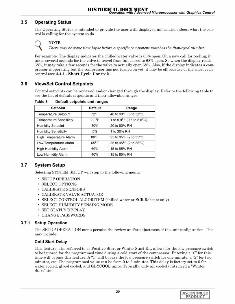
Table 1 Default setpoints and rangesSetpoint Default Range
Temperature Setpoint 72°F 40 to 90°F (5 to 32°C)
Temperature Sensitivity 2.0°F 1 to 9.9°F (0.6 to 5.6°C)
Humidity Setpoint 50% 20 to 80% RH
Humidity Sensitivity 5% 1 to 30% RH
High Temperature Alarm 80°F 35 to 95°F (2 to 35°C)
Low Temperature Alarm 65°F 35 to 95°F (2 to 35°C)
High Humidity Alarm 60% 15 to 85% RH
Low Humidity Alarm 40% 15 to 85% RH
DISCONTINUED PRODUCT
HISTORICAL DOCUMENT

Operation with Advanced Microprocessor Controls
7
2.5.2 Setup SystemThe Setup System menu includes the following selections:
• SETUP OPERATION• SELECT OPTIONS• CALIBRATE SENSORS• SHOW DIP SWITCHES• SELECT CONTROL TYPE (Chilled Water or SCR Reheats only)• SETUP ALARMS• HUM CONTROL METHOD• ANALOG SETUP• SET STATUS DISPLAY• CALIBRATE ACTUATOR
Setup OperationThe Setup Operation menu permits the review and/or adjustment of the unit configuration. This may include:
Cold Start—This feature, also referred to as Positive Start or Winter Start Kit, allows for the low pressure switch to be ignored for the programmed time during a cold start of the compressor. Enter-ing a “0” for this time will bypass this feature. A “1” will bypass the low pressure switch for one minute, a “2” for 2 minutes, etc. The programmed value can be from 0 to 3 minutes. This delay is fac-tory set to 0 for water cooled, glycol cooled, and GLYCOOL units. Typically, only air cooled units need a “Winter Start” delay time.
Restart—This feature allows for the unit to restart automatically after a loss of power. The pro-grammed value is in 0.1 minute (6 seconds) intervals. A programmed value of zero (0) would require the user to manually press the ON/OFF key to start the unit, i.e. no auto restart. The purpose of this feature is to prevent several units from starting at the same time after a loss of power. The message “Restart Delay -- Please Wait” will be displayed when the system is in the auto restart mode. Liebert suggests programming multiple unit installations with different auto restart times.
IR Fill Rate (infrared humidifiers only)—An autoflush system automatically controls a water makeup valve to maintain the proper level in the infrared humidifier water pan during humidifier operation. If humidification is needed and 15 hours have elapsed since the last time the humidifier was on, the humidifier is held off until the valve completes an initial fill of the humidifier pan. This pre-fill is about 30 seconds. The valve continues to fill and flush the pan for about 4 minutes.
During humidifier operation, with the flush rate set at the default of 150%, the valve is opened peri-odically to add water to the pan (about 40 seconds for every 9-1/2 minutes of humidifier operation). This adds enough water to the pan to cause about a third of the total water used to be flushed out the overflow standpipe located in the humidifier pan. This flushing action helps remove solids from the pan. The flush rate is adjustable from 110% to 500%. If the water quality is poor, it may be desirable to increase the water flushing action above the normal 150% rate. Also, if the supply water pressure is low, the flush rate adjustment can be increased so that sufficient water level is maintained during humidification.
Chilled Water/Hot Water/Econ-O-Coil Flush—This feature will flush the respective coil for 3 minutes after the programmed number of hours of non-use. For example, if the flush time is pro-grammed with 24 hours on a hot water reheat type system and heating is not required for a 24 hour period, the hot water valve will be open for 3 minutes to allow the coil to be flushed. The programmed value can be from 0 (no flush) to 99 (99 hours of non-use).
C/F Degrees—The control can be selected to show readings and setpoints in either degrees Fahren-heit (F) or Celsius (C).
DISCONTINUED PRODUCT
HISTORICAL DOCUMENT

Operation with Advanced Microprocessor Controls
8
Table 2 lists the setup functions, their factory default values and the allowable programming ranges.
Select OptionsThe following table lists options which should match the options installed with your unit and should not need to be changed during normal operation.
Calibrate SensorsThe temperature and humidity sensors can be calibrated by selecting this menu item. “SENSOR” shows the actual sensor reading or raw reading. “CALIBRATED” shows the sensor reading after the calibration offset has been added. The temperature sensor can be calibrated ±5 degrees Fahrenheit and the humidity sensor can be calibrated ±10%RH. When calibrating the humidity sensor, the value shown will always be % RH, even though absolute humidity control may be selected. If absolute humidity control is selected, the Normal Status Display will display the adjusted reading and may not agree with the relative humidity reading displayed while in calibration.
Show DIP SwitchesThe DIP switch settings can be reviewed from the display panel. Changing the DIP switches requires opening the upper panel for access to the DIP switches on the microprocessor control board.
The selections shown in Table 4 should match options installed on your unit and should not need to change during normal operation. Switches 1 through 7 are self explanatory. DIP switch 8, not shown in the table, enables the password feature when set to ON and disables the password feature when set to OFF.
Table 2 Setup functions, default values and rangesFunction Default Range
Cold Start Time Delay* 3 0 to 3 min (0 = no delay)Restart Time Delay 0.1 0 to 9.9 min (0 = manual restart)Infrared Fill Rate 150 110 to 500%Chilled/Hot Water Coil Flush 24 0 to 99 hrs (also Econ-O-Coil)C/F Degrees F C or F*Factory set to 0 for water cooled, glycol, and GLYCOOL units.
Table 3 Unit optionsOption Selection
Heating1 Yes or NoHumidifier Yes or NoDehumidifier Yes or NoHot Gas Reheat2 Yes or NoHeat Stages3 21Heating cannot be disabled on units with SCR reheats.2Hot gas reheat not available on units with SCR reheats.3Heat stages not selectable on units with SCR reheats.
NOTEPower MUST be cycled OFF, then ON from the unit disconnect switch for the control system to update the DIP switch settings (with the exception of switch 8).
Table 4 DIP switch settingsSwitch # Off On
1 No Part Coil Part Coil/Chilled Water2 Electric/Hot Gas Reheat Hot Water Reheat3 All Not Used4 No GLYCOOL GLYCOOL5 No Dual Cooling Dual Cooling6 Not Used Not Used7a Tight Control Standard Control
a SCR reheats only (with special software); otherwise, not used.
DISCONTINUED PRODUCT
HISTORICAL DOCUMENT

Operation with Advanced Microprocessor Controls
9
Select Control Type • Intelligent (Chilled Water only)• Proportional (all unit types)• Tunable PID (Chilled Water or SCR Reheats only)
The type of system control method used by the microprocessor can be selected from the front panel. The default setting is Intelligent, which approximates the actions that a human operator would take to maintain precise, stable control. The control logic uses Artificial Intelligence techniques including “fuzzy logic” and “expert systems” methods to maintain precise, stable control and increase reliability by reducing component cycles. Proportional is a standard control method that uses one gain factor (temperature sensitivity adjustment). Tunable PID (Proportional, Integral, and Derivative) uses three gain factors selected by the operator. PID allows precision tuning, but requires an experienced operator and seasonal adjustments. Note that if PID is selected, it is used for temperature control while humidity will continue to use Proportional control. Refer to 4.0 - System Performance with Advanced Microprocessor Controls for more detail on types of controls.
Setup AlarmsSelecting SETUP ALARMS will step to the following menu:
• SET TIME DELAYS• ENABLE ALARMS• ENABLE COMMON ALARM• SET CUSTOM ALARMS
Each individual alarm can be programmed with a time delay from 0 to 255 seconds. Each individual alarm can be ENABLED or DISABLED and each individual alarm can be programmed to energize or not to energize the Common Alarm Relay.
Set Time Delays—By programming a time delay for an alarm, the system will delay the specified amount of time before recognizing the alarm. The alarm condition must be present for the amount of time programmed for that alarm before it will be annunciated. If the alarm condition goes away before the time delay has timed out, the alarm will not be recognized and the time delay timer will be reset. For software alarms such as Loss of Power, Short Cycle, and Low Suction Pressure, a time delay will only delay the annunciation of that alarm. The condition of the alarm is not applicable because the condition has already occurred. For these alarms the time delay should be left at the fac-tory default of 0. Table 5, below, shows the default time delays for each alarm.
Table 5 Alarm default time delays
AlarmDefault Time
Delay (seconds)Humidifier Problem 2High Head Pressure 2Change Filter 2Loss of Air flow 3Custom Alarm #1 0Custom Alarm #2 0Custom Alarm #3 0Custom Alarm #4 6High Temperature 30Low Temperature 30High Humidity 30Low Humidity 30Low Suction Pressure 0Short Cycle 0Compressor Overload 2Main Fan Overload 5Loss of Power 0
DISCONTINUED PRODUCT
HISTORICAL DOCUMENT

Operation with Advanced Microprocessor Controls
10
Enable Alarms—Each individual alarm can be selected to be ENABLED (annunciated audibly, visu-ally, and communicated to a Site Products System) or DISABLED (ignored).
Enable Common Alarm—Each individual alarm can be selected to energize or to not energize the common alarm relay. If the energize common alarm function is set to YES, the relay is energized immediately as the alarm is annunciated and de-energized when the alarm condition goes away (only after the alarm has been recognized). If the function is set to NO, the alarm has no effect on the com-mon alarm relay regardless of whether the alarm is ENABLED or DISABLED.
Set Custom Alarms—The custom alarm messages can be from a list of standard alarm messages or you can write your own message.
They can be in any location(s) 1 through 4. The text for custom alarms can be changed at any time by selecting “SET CUSTOM ALARMS.” To change the text for a custom alarm, select “SELECT ALARM.” Then, select the alarm you would like to change, 1 through 4. Using the UP/DOWN arrows will step through the list of five standard alarm messages (see list below) and the two custom alarms.
Press ENTER to make your selection. To modify the two custom alarm messages, go back one screen and select “CHANGE CUSTOM TXT 1” (or 2). Text can be up to 20 characters in length and can be any of the following characters (or a blank space):
ABCDEFGHIJKLMNOPQRSTUVWXYZ#%*-0123456789.
Standard Custom Alarm Messages
• WATER UNDER FLOOR• SMOKE DETECTED• STANDBY GC PUMP ON• LOSS OF WATER FLOW• STANDBY UNIT ON
For more information concerning alarms, see 5.0 - Alarm Descriptions.
Humidity (HUM) Control MethodThe user may select between relative (direct) and absolute (predictive) humidity control. If relative is selected, the RH control is taken directly from the RH sensor. If absolute is selected, the RH control is automatically adjusted as the return air temperature deviates from the desired temperature setpoint. This results in a predictive humidity control. The display will indicate % RH for both methods of con-trol, but the adjusted humidity reading will be displayed if absolute is selected. With absolute humid-ity control, the humidity control is automatically adjusted approximately 2% RH for each degree difference between the return air temperature and the temperature setpoint.
With relative humidity control, unnecessary dehumidification can result when overcooling occurs dur-ing a dehumidification cycle. This is because a higher than normal RH reading is caused by overcool-ing the room (about 2% RH for each degree of overcooling). This extends the dehumidification cycle. Later, when the dehumidification ends and the temperature rises to the setpoint, the RH reading falls. The final RH reading will then be lower than actually desired. If the overcooling was significant enough, the RH could be low enough to activate the humidifier.
If absolute humidity control is selected, over-dehumidification is avoided. When overcooling occurs, causing an increase in the RH reading, the humidity control program “predicts” what the RH will be when the dehumidification cycle ends and temperature returns to the setpoint. This allows the dehu-midification cycle to end at the proper time. The predictive humidity control can reduce energy con-sumption by minimizing compressor and reheat operation, and eliminating unnecessary humidifier operation.
NOTEA maximum of two of the alarm messages can be your own message.
NOTEThe two custom alarm messages will be shown with what was previously programmed in them and can be changed.
DISCONTINUED PRODUCT
HISTORICAL DOCUMENT
Operation with Advanced Microprocessor Controls
11
Analog SetupFor installation of analog sensors, see 4.5.1 - Connecting the Analog Sensors.
After selecting a compatible sensor and properly wiring it to the terminals, set up the control to mon-itor the sensor as follows:
Slope—The slope is a multiplier used to scale the input signal. The slope can be positive (rising) or negative (falling) and can range from 0 (resulting in a horizontal line) to ±999. The slope for a 0-5 volt input is per 1 volt input, for 0-10 volt input is per 2 volt input, and for 4-20 mA is per 4 mA input. For example, assuming an intercept of 0, for a 0-10 volt sensor input with a slope of 50, an input of 1 volt would be displayed as 25: 1x(50/2); 2 volts would be 50: 2x(50/2); 3 volts would be 75: 3x(50/2); etc.
Intercept—The intercept is an offset from point 0 corresponding to 0 volts or 0 mA input. The inter-cept can be positive or negative and can be a point from 0 to ±999.
Adding an intercept of 100 to the slope example above, 1 volt would be 125: 100 + (1x[50/2]); 2 volts would be 150: 100 + (2x[50/2]); 3 volts would be 175: 100 + (3x[50/2]); etc.
Text—You may enter a custom label for each analog input. The text label can be 20 characters in length including any of the following:
ABCDEFGHIJKLMNOPQRSTUVWXYZ#%*-0123456789, or space.
Set Status DisplayThe Status Display can be set to display the return air temperature and humidity SENSOR READ-INGS or the temperature and humidity control SETPOINTS through this selection. When SET-POINTS is selected, the status display indicates so by displaying “SETPTS.” If SENSOR READINGS is selected, the Status Display will show the return air sensor readings.
Calibrate ActuatorFor systems that use a valve actuator for chilled water or GLYCOOL cooling, the actuator timing may be calibrated or adjusted. This is the time it takes for the valve to travel from full closed to full open. It is programmable from 0 to 255 seconds. The factory default time is 165 seconds and should not be changed unless the actual valve travel time is not correct. The full valve travel time is used by the control to determine the appropriate valve position. For example, if the valve travel time is 165 sec-onds and 50% cooling is being called for, the valve will open for 83 seconds to acheive 50% open. To change the valve travel time, first enter the “CALIBRATE ACTUATOR” screen. The display will show the present period used by the control for valve actuator full travel. Press ENTER and adjust the time using the UP/DOWN arrows. When the correct time is displayed, press ENTER to store the new time to memory.
NOTEFor a 4-20 mA input sensor, if the desired reading at 4 mA input is 0, then an intercept of-1 x slope would be required. For example, assuming a slope of 50, the formula would be([-1 x 50] + 4 x [50/4]) = 0. The intercept is -50.
DISCONTINUED PRODUCT
HISTORICAL DOCUMENT
Operation with Advanced Microprocessor Controls
12
2.5.3 Run DiagnosticsBy selecting Run Diagnostics, maintenance personnel can check system inputs, outputs, and complete a test of the microcontroller circuit board, all from the front panel. Review of the system inputs and the microcontroller test can be done without interrupting normal operation. To test the system out-puts, the normal system control is temporarily suspended. DO NOT leave the unit in the diagnostics mode any longer than is necessary for troubleshooting. The control system will return to normal oper-ation in 5 minutes, automatically, if no key is pressed.
Show InputsWith the unit on and the fan running, the input state for the following devices may be displayed:
• Air sail switch: normally off unless Loss of Air Alarm is active• Custom alarm #1: normally off unless this alarm is active• Custom alarm #2: normally off unless this alarm is active• Custom alarm #3: normally off unless this alarm is active• Custom alarm #4: normally off unless this alarm is active• Humidifier problem: normally on unless this alarm is active• Filter clog: normally off unless Change Filters Alarm is active• Main fan overload: normally on unless Main Fan Overload Alarm is active• Shutdown device: normally on unless unit is off through the Fire Stat or Remote Shutdown
Device• Low press switch: normally on if compressor circuit is in operation• Comp overload: normally on unless Compressor Overload Alarm is active• High head comp: normally off unless High Head Pressure alarm Compressor is active
Test OutputsWhen this feature is selected, the unit is effectively turned off. When stepping from one load to the next, the previous load, if on, is turned off automatically. The loads can also be toggled ON/OFF by selecting “ENTER.” Once turned on, the output will remain on for 5 minutes unless toggled off or the Test Outputs function is exited by selecting “MENU/ESC.” (The compressor is limited to 15 seconds on to prevent damage.) The outputs are as follows:
• Main fan: main fan contactor• Comp: compressor contactor• LLSV: liquid line solenoid valve• HGBP/CUV: hot gas bypass or compressor unloader valve (on certain units)• Part coil: part coil solenoid valve• CWV/CGV: chilled water or GLYCOOL valve• R5 Relay: Relay 5 (heat rejection)• Reheat 1: Reheat 1 contactor (also energizes fan for safety) or SCR Reheats• Reheat 2: Reheat 2 contactor (also energizes fan for safety)• HWR: hot water solenoid valve• Humidifier: humidifier contactor (also energizes humidifier makeup valve and fan for safety)• HMV: humidifier makeup valve • Comm alarm: common alarm relay
Test Control BoardBy selecting this function, the microcontroller will perform a self test lasting approximately 10 sec-onds. At the end of the test, the ROM checksum, ROM part number and version number will be dis-played.
! CAUTIONDo not test a compressor output for more than a few seconds. Compressor damage could result!
DISCONTINUED PRODUCT
HISTORICAL DOCUMENT

Operation with Advanced Microprocessor Controls
13
2.5.4 Change PasswordsThe display prompts you to enter a three digit password when making changes. The system includes two (2) passwords, one for setpoints and one for setup. The system allows the passwords to be changed by first entering the present password, factory set as “123” for setpoints and “321” for setup. The pass-word function provides system security, so only personnel authorized to make changes should know the passwords. If unauthorized changes are being made, the passwords may be compromised and new ones should be selected. The password function can be disabled by setting DIP switch 8 to OFF.
2.6 Date and TimeThe current date and time is available through the display. This feature allows the date and time to be read or changed and is accessed by selecting “DATE AND TIME” from the Main Menu.
The “DATE AND TIME” is used only by the control for recording the Alarm History.
2.7 Status DisplayThe Status Display selected from the Main Menu is the same Status Display that is normally on the screen. While the Main Menu is displayed, you can press the MENU/ESC key to return to the Status Display.
2.8 Control Circuit BoardThe control circuit board is located inside the unit behind the LCD display and control key panel. Open the front panel for access to the board.
The control board includes an adjustment for LCD display contrast, nonvolatile memory, DIP switches (which should not require customer changes), control output LEDs and jumpers for board configuration. The jumpers should be placed as follows:
P5—removedP12—removedP19—installed on Pins 1 and 2P47—installed on Pins 1 and 2P48—installed on Pins 1 and 2P50—all jumpers installed for 4-20 mA analog inputs. See 4.5.1 - Connecting the Analog Sen-sors for other configurationsP51—removed
2.8.1 LCD Display ContrastThe level of contrast due to viewing angle of the LCD display can be adjusted using a small thumb wheel at the upper left of the control board just under the cable going to the display. The control is labeled R6.
NOTEThe clock uses the 24 hour system (For example: 17:00 would be 5:00 PM). The date and time are backed up by battery.
NOTEThe system automatically returns to the Status Display in five minutes if no control keys are pressed.
NOTEThe LED backlighting on the text (4 x 20) display is always lit.
DISCONTINUED PRODUCT
HISTORICAL DOCUMENT

Operation with Advanced Microprocessor Controls
14
2.8.2 Non-Volatile MemoryAll critical information is stored in nonvolatile memory. Setpoints, setup parameters, and component run hours are kept inside the microcontroller in EEPROM. Information retained for the alarm history is kept in non-volatile RAM.
2.8.3 DIP SwitchesEquipment options are selected and enabled using DIP switches 1 through 7. These are located at the upper left of the control board and are labeled SW1. Switch 1 is at the top. These switches are factory set and should not require any user changes. The setting and function of the switches can be read from the LCD display (see Show DIP Switches on page 8 or the accompanying Table 4).
2.8.4 Control OutputsActive control outputs are indicated with LEDs on the lower section of the control board. Each LED is lit if the control output is active (on). The LEDs assist in troubleshooting the system. Refer to the fol-lowing table.
Table 6 Control output LEDsLED Control Output
R5 Heat Rejection
LLSV Liquid Line Solenoid Valve
HGBP Hot Gas By-Pass or Compressor Unloader Valve
C1 Compressor
RH1 Reheat Stage 1, Hot Gas, Hot Water Reheat Solenoid or SCR Reheats
RH2 Reheat Stage 2
HUM Humidifier
FAN Main Fan
HMV Humidifier Make-Up Valve
LLSV2 Part Coil Solenoid Valve
DISCONTINUED PRODUCT
HISTORICAL DOCUMENT

Operation with Advanced Microprocessor with Graphics Control
15
3.0 OPERATION WITH ADVANCED MICROPROCESSOR WITH GRAPHICS CONTROL
The advanced microprocessor with graphics (G) control for your Liebert Challenger 3000 unit features an easy to use, menu driven LCD Graphics Display. The menus, control features, and circuit board details are described in this section. For more details on the control refer to 4.0 - System Perfor-mance with Advanced Microprocessor Controls; for details on the alarms refer to 5.0 - Alarm Descriptions.
3.1 BasicsControl keys include ON/OFF, Menu/ESCape, ENTER, Increase (UP) arrow, and Decrease (DOWN) arrow. Refer to Figure 3. These keys are used to move through the menus as prompted on the LCD display (refer to Figure 4).
To turn the unit ON, press the ON/OFF key after power is applied. To turn the unit OFF, press the ON/OFF key before power is disconnected.
Active alarms are indicated on the LCD screen by a ringing bell. Alarms are also annunciated by an audible beeper. To silence an alarm, press the ENTER key as prompted on the display. The unit stores the 60 most recent alarms for review.
Setpoints, DIP switch settings, and other selections were made on your unit before testing at the fac-tory and are kept in nonvolatile memory. Setpoints were chosen based on typical operating experi-ence. Other selections were made based on options included with your unit. Make adjustments to the factory default selections ONLY if they do not meet your specifications. When entering setpoints, time delays, etc., the allowable ranges are displayed and may require a password, if enabled.
Figure 3 Advanced microprocessor with graphics (G) control panel
DISCONTINUED PRODUCT
HISTORICAL DOCUMENT

Operation with Advanced Microprocessor with Graphics Control
16
Figure 4 Advanced microprocessor with graphics control menu
* Select Control Algorithm available on Chilled Water only** optional*** Himod units only
Date andTime
Analog/Digital InputsPlot GraphsView/Set
AlarmsOperating
StatusView/SetControl
SetpointsSetup
SystemRun
DiagnosticsView RunHours Log
Normal DisplayAny key exceptON/OFF
ESC key
Use UP/DOWN to movethe cursor. Hit ENTERto select the menu item.
ESC key moves backwardthrough menus toward theMain Menu
Date and Time
Set Clock
View/Set Alarms
Active AlarmsAlarm HistorySetup AlarmsHigh Temperature
Low TemperatureHigh HumidityLow Suction PressureShort CycleCompressor OverloadMain Fan OverloadLoss of PowerHumidifier ProblemHigh Head PressureChange FiltersLoss of Air FlowCustom Alarm 1Custom Alarm 2Custom Alarm 3Custom Alarm 4
Setup Custom AlarmsSetup Custom Alarm TextChange Custom Text 1Change Custom Text 2Change Custom Text 3Change Custom Text 4
View WaterDetect Floor Plan
Setup WaterDetect Floor PlanUse / to locate fileUse ENTER to define file
Temperature PlotHumidity PlotAnalog Sensor #1 PlotAnalog Sensor #2 PlotAnalog Sensor #3 PlotAnalog Sensor #4 PlotModify Plot ScalesModify Temp ScalesModify Humidity ScalesModify Analog Sensor
# 1 Scale # 2 Scale # 3 Scale # 4 Scale
Plot Graphs
Run Diagnostics
Show InputsAir Sail SwitchCustom Alarm 1Custom Alarm 2Custom Alarm 3Custom Alarm 4Humidifier ProblemFilter Clog SwitchMain Fan OverloadShutdown DeviceLow Pressure
SwitchCompressor
OverloadHigh Head Pressure
Test OutputsMain Fan
CompressorLiquid Line SVHGBP/CUVCW/CGVDehumidification***R5 RelayReheat 1Reheat 2RH3 Dehum
DamperHumidifierHMVCommon Alarm
Test Control BoardMicrocontroller
Show DIP SwitchesDipswitch 1Dipswitch 2Dipswitch 3Dipswitch 4Dipswitch 5Dipswitch 6Dipswitch 7
72°F Unit On50%RHDehumidifyingCooling
***Main Menu***
Compressor Cooling %Heating %GLYCOOL %**Chilled Water Valve %**Dehumidification % Humidification %
Operating Status View/Set Setpoints
Temperature SetpointSensitivity SetpointHumidity SetpointSensitivityHigh Temperature AlarmLow Temperature AlarmHigh Humidity AlarmLow Humidity Alarm
View 24 Hour Run Time History
Chilled Water**GLYCOOL**CompressorReheat 1,2HumidifierMain Fan
View Total Run HoursCompressorGLYCOOL**Chilled Water Valve**Main FanHumidifierReheat 1,2Heat Rejection
View Run Hours Log
Analog/Digital Inputs
Read Analog InputsAnalog Input 1
Analog Input 2Analog Input 3Analog Input 4
Set Analog InputsAnalog Input 1 (2,3,4) Slope Units Text Intercept
Read Digital InputsSetup Digital nputs
(How-to Text)
Setup OperationCold Start DelayAuto Restart DelayIR Flush OverfillCW / HW Coil Flush**Display in Degrees (F / C)Min Chilled Water Temp**
Select OptionsReheatHumidifyDehumidifyHot Gas ReheatStages of Reheat
Calibrate SensorsTemperature SensorHumidity SensorCalibrated Reading
Calibrate Valve ActuatorSelect Control Algorithm*
ProportionalIntelligentTunable PID
Proportional GainDerivative GainIntegral Gain
Select HumiditySensing Mode
RelativeAbsolute
Set Status DisplaySensor ReadingSetpoints
Change PasswordsSetpoint PasswordSetup Password
Change Passwords
Setup System
DISCONTINUED PRODUCT
HISTORICAL DOCUMENT

Operation with Advanced Microprocessor with Graphics Control
17
3.2 Status DisplayThe normal status screen is divided into two sections, a right half and a left half. The left half displays the return air temperature and humidity readings in large characters.
The right half of the screen is divided into four quadrants (top to bottom). In the four quadrants, six different graphic symbols may be displayed depending on the unit status. At the top there will be a moving hammer striking a bell that appears when an alarm is present. The word “Alarm” also appears next to the hammer and bell. The second quadrant down displays a rotating fan as long as the unit is turned on and the fan is running. The words “Unit on” appear next to the fan symbol. The third quadrant may display one of two symbols relating to heating or cooling. If the control is calling for cooling, a growing snowflake is shown next to the word “Cooling.” If the control is calling for heat-ing, three moving heat rays are displayed next to the word “Heating.” In the bottom quadrant, there may be one of two symbols relating to humidification and dehumidification. If the control is calling for humidification, a growing water drop is shown next to the word “Humidification.” If the control is call-ing for dehumidification, a shrinking water drop is shown next to the word “Dehumidification.”
3.3 Main Menu <MENU/ESC>Press the MENU/ESC key to display the Main Menu. The Menu selections include:
• VIEW/SET ALARMS• OPERATING STATUS• VIEW/SET CONTROL SETPOINTS• SYSTEM SETUP• RUN DIAGNOSTICS• DATE AND TIME• PLOT GRAPHS• ANALOG/DIGITAL INPUTS• VIEW RUN HOURS LOG
Pressing the MENU/ESC key while the Main Menu is displayed will return the screen to the Status Display.
3.4 View/Set AlarmsSelecting VIEW/SET ALARMS will step to the following menu:
• ACTIVE ALARMS• ALARM HISTORY LOG• SETUP ALARMS• SETUP CUSTOM ALARMS• VIEW WATER DETECT FLOOR PLAN• SETUP WATER DETECT FLOOR PLAN
3.4.1 Active AlarmsThis screen displays any active alarm. The alarms are numbered, #1 being the most recent. The type of alarm (Urgent or Warning) is also displayed. If there are no active alarms, then “NO ALARMS PRESENT” will be displayed.
3.4.2 Alarm History LogA history of the 60 most recent alarms is kept in nonvolatile memory complete with the type of alarm, the alarm name, and the date and time it occurred. The first alarm in the history is the most recent and the last (up to 60) is the oldest. If the Alarm History is full (60 alarms) and a new alarm occurs, the oldest is lost and the newest is saved in alarm history location 1. The rest are moved down the list by 1. Alarm history on new units may show the results of factory testing.
NOTEThe display can also be set to display the temperature and humidity setpoints. See 3.7.7 - Set Status Display.
DISCONTINUED PRODUCT
HISTORICAL DOCUMENT

Operation with Advanced Microprocessor with Graphics Control
18
3.4.3 Setup AlarmsThe list of alarms may be reviewed using the UP/DOWN keys. Any alarm may be selected to have it's parameters modified by pressing the ENTER key. All alarms have a time delay and alarm type parameter. The high/low temperature and humidity alarms also have a programmable Trip Point. The Trip Point is the point at which the alarm is activated. By programming a time delay for an alarm, the system will delay the specified amount of time before recognizing the alarm. The alarm condition must be present for the amount of time programmed for that alarm before it will be annun-ciated. If the alarm condition goes away before the time delay has timed out, the alarm will not be rec-ognized. For software alarms such as Loss of Power, Short Cycle, and Low Suction Pressure, a time delay will only delay the annunciation of that alarm. The condition of the alarm is not applicable because the condition has already occurred. For these alarms, the time delay should be left at the fac-tory default of 0.
The following table shows the default time delays for each alarm.
Each individual alarm can be selected as either DISABLED, WARNING, or URGENT. The four cus-tom alarms may also be selected to be a Status Only input. If the alarm is DISABLED, it is ignored. If the alarm is WARNING or URGENT, it will be annunciated audibly, visually, and communicated to a Site Products System if appropriate. When the alarm is selected to be a WARNING, the alarm will NOT activate the common alarm relay. When the alarm is selected to be URGENT, the alarm is first annunciated as a WARNING, and then annunciated again, after the programmed time delay. When the alarm becomes URGENT, the control will activate the common alarm relay. The common alarm relay is de-energized after the alarm has been recognized and when the alarm no longer exists. When the alarm type has been selected to be URGENT, the allowable range for the time delay from warning to urgent is 0 minutes to 999 hours. When any of the four custom alarm inputs have been selected as Status Only, they become digital inputs for monitoring only and are no longer treated as alarms.
Table 7 Alarm default time delays
AlarmDefault Time
Delay (seconds)
Humidifier Problem 2
High Head Pressure 2
Change Filter 2
Loss of Air flow 3
Custom Alarm #1 0
Custom Alarm #2 0
Custom Alarm #3 0
Custom Alarm #4 6
High Temperature 30
Low Temperature 30
High Humidity 30
Low Humidity 30
Low Suction Pressure 0
Short Cycle 0
Compressor Overload 2
Main Fan Overload 5
Loss of Power 0
DISCONTINUED PRODUCT
HISTORICAL DOCUMENT

Operation with Advanced Microprocessor with Graphics Control
19
3.4.4 Setup Custom AlarmsSelecting SETUP CUSTOM ALARMS will step to the following menu:
• SETUP CUSTOM ALARM TEXT• CHANGE CUSTOM TEXT 1• CHANGE CUSTOM TEXT 2• CHANGE CUSTOM TEXT 3• CHANGE CUSTOM TEXT 4
The custom alarm messages can be selected from a list of standard messages or you can write your own messages. The message selected for any custom alarm can be changed at any time by selecting SETUP CUSTOM ALARM TEXT. A list of five standard messages (see list below) and four custom messages are available to choose from. To modify the custom messages press CHANGE CUSTOM TEXT 1 (2, 3 or 4). Each message can be up to 20 characters in length and can be any of the following characters (or a blank space):
ABCDEFGHIJKLMNOPQRSTUVWXYZ#%*-0123456789.
Standard Custom Alarm Messages
• WATER UNDER FLOOR• SMOKE DETECTED• STANDBY GC PUMP ON• LOSS OF WATER FLOW• STANDBY UNIT ON
For more information concerning alarms, see 5.0 - Alarm Descriptions.
3.4.5 View Water Detect Floor Plan (for Optional LTM1000/LT750)When water is detected the alarm will sound and the WATER UNDER FLOOR alarm message will be displayed. To see where the water is in the room, select VIEW/SET ALARMS from the main menu, then VIEW WATER DETECT FLOOR PLAN. A tile will be highlighted and blinking to indicate the position of the detected water.
3.4.6 Setup Water Detect Floor PlanThe selected (i.e., cursor) floor tile will be highlighted and blinking. The UP and DOWN arrow keys are used to position the cursor tile. The UP key will move the cursor tile up and then it wraps around to the bottom of the next column to the right. The DOWN arrow key moves the cursor down, then to the top of the next column to the left. The cursor will also wrap around from the right top tile to the left bottom tile and back.
There are three different types of tiles to be defined: the environmental unit, the LT750 and sensor cable tiles. To set up the cable layout, first move the cursor to the location of the environmental unit and press the ENTER key. A rectangular box will be drawn at that location. Then move the cursor to the location of the LT750 and press the ENTER key. A solid circle will be drawn on the display. No tile can have two definitions, so if the LT750 is physically directly under the unit it must be defined at least one tile away.
The sensor cable should not be defined one tile at a time. The only sensor cable tiles that need to be defined are the tiles where the cable is going to change direction, and the last tile. The display will automatically define any tiles between two consecutively defined sensor tiles to be sensor tiles.
The ENTER key is also used to undo tile definitions. If a tile is defined in the wrong place, position the cursor on that tile and press the ENTER key. It will undefine the tile under the cursor and move the cursor back to the last defined tile. The entire layout can be erased by successively pressing the ENTER key. When the last tile is defined, press the ESCape key to leave the setup screen.
For more information and detailed installation instructions, see 4.5.2 - Water Detection Display.
DISCONTINUED PRODUCT
HISTORICAL DOCUMENT
Operation with Advanced Microprocessor with Graphics Control
20
3.5 Operating StatusThe Operating Status is intended to provide the user with displayed information about what the con-trol is calling for the system to do.
For example: The display indicates the chilled water valve is 68% open. On a new call for cooling, it takes several seconds for the valve to travel from full closed to 68% open. So when the display reads 68%, it may take a few seconds for the valve to actually open 68%. Also, if the display indicates a com-pressor is operating but the compressor has not turned on yet, it may be off because of the short cycle control (see 4.4.1 - Short Cycle Control).
3.6 View/Set Control SetpointsControl setpoints can be reviewed and/or changed through the display. Refer to the following table to see the list of default setpoints and their allowable ranges.
3.7 System SetupSelecting SYSTEM SETUP will step to the following menu:
• SETUP OPERATION• SELECT OPTIONS• CALIBRATE SENSORS• CALIBRATE VALVE ACTUATOR• SELECT CONTROL ALGORITHM (chilled water or SCR Reheats only)• SELECT HUMIDITY SENSING MODE• SET STATUS DISPLAY• CHANGE PASSWORDS
3.7.1 Setup OperationThe SETUP OPERATION menu permits the review and/or adjustment of the unit configuration. This may include:
Cold Start DelayThis feature, also referred to as Positive Start or Winter Start Kit, allows for the low pressure switch to be ignored for the programmed time during a cold start of the compressor. Entering a “0” for this time will bypass this feature. A “1” will bypass the low pressure switch for one minute, a “2” for two minutes, etc. The programmed value can be from 0 to 3 minutes. This delay is factory set to 0 for water cooled, glycol cooled, and GLYCOOL units. Typically, only air cooled units need a “Winter Start” time.
NOTEThere may be some time lapse before a specific component matches the displayed number.
Table 8 Default setpoints and rangesSetpoint Default Range
Temperature Setpoint 72°F 40 to 90°F (5 to 32°C)
Temperature Sensitivity 2.0°F 1 to 9.9°F (0.6 to 5.6°C)
Humidity Setpoint 50% 20 to 80% RH
Humidity Sensitivity 5% 1 to 30% RH
High Temperature Alarm 80°F 35 to 95°F (2 to 35°C)
Low Temperature Alarm 65°F 35 to 95°F (2 to 35°C)
High Humidity Alarm 60% 15 to 85% RH
Low Humidity Alarm 40% 15 to 85% RH
DISCONTINUED PRODUCT
HISTORICAL DOCUMENT

Operation with Advanced Microprocessor with Graphics Control
21
Auto Restart DelayThis feature allows for the unit to restart automatically after a loss of power. The programmed value is .1 minute (6 seconds) intervals. A programmed value of zero (0) would require the user to manually press the ON/OFF switch to start the unit, i.e. no auto restart. The purpose of this feature is to pre-vent several units from starting at the same time after a loss of power. The message “Restart Delay -- Please Wait” will be displayed when the system is in the auto restart mode. Liebert suggests pro-gramming multiple unit installations with different auto restart times.
IR Flush Overfill (infrared humidifiers only)An autoflush system automatically controls a water makeup valve to maintain proper level in the infrared humidifier water pan during humidifier operation. If humidification is needed and 30 hours have elapsed since the last time the humidifier was on, then the humidifier is held off until the valve completes an initial fill of the humidifier pan. This pre-fill is about 15 seconds. The valve continues to fill and flush the pan for about 4 minutes.
During humidifier operation, with the flush rate set at the default of 150%, the valve is opened peri-odically to add water to the pan (about 40 seconds for every 9-1/2 minutes of humidifier operation). This adds enough water to the pan to cause about a third of the total water used to be flushed out the overflow standpipe located in the humidifier pan. This flushing action helps remove solids from the pan. The flush rate is adjustable from 110% to 500%. If the water quality is poor, it may be desirable to increase the water flushing action above the normal 150% rate. Also, if the supply water pressure is low, the flush rate adjustment can be increased so that sufficient water level is maintained during humidification.
Chilled Water/Hot Water/Econ-O-Coil FlushThis feature will flush the respective coil for 3 minutes after the programmed number of hours of non-use. For example, if the flush time is programmed with 24 hours on a hot water reheat type sys-tem, and heating is not required for a 24 hour period, the hot water valve will be opened for 3 minutes to allow the coil to be flushed. The programmed value can be from 0 (no flush) to 99 (99 hours of non-use).
Display in DegreesThe control can be set to display readings and setpoints in either degrees Fahrenheit (F) or Celsius (C).
Default Settings and RangesThe following table lists the setup functions, their factory default values, and the allowable ranges for which they can be programmed.
Table 9 Setup functions, default values and rangesFunction Default Range
Cold Start Time Delay* 3 0 to 3 min (0 = no delay)
Restart Time Delay 0.1 0 to 9.9 min (0 = manual restart)
Infrared Fill Rate 150 110 to 500%
Chilled/Hot Water Coil Flush 24 0 to 99 hrs (also Econ-O-Coil)
C/F Degrees F C or F*Factory set to 0 for water cooled, glycol, and GLYCOOL units.
DISCONTINUED PRODUCT
HISTORICAL DOCUMENT
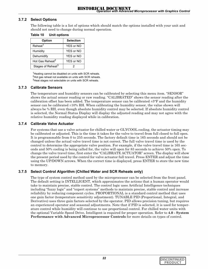
Operation with Advanced Microprocessor with Graphics Control
22
3.7.2 Select OptionsThe following table is a list of options which should match the options installed with your unit and should not need to change during normal operation.
3.7.3 Calibrate SensorsThe temperature and humidity sensors can be calibrated by selecting this menu item. “SENSOR” shows the actual sensor reading or raw reading. “CALIBRATED” shows the sensor reading after the calibration offset has been added. The temperature sensor can be calibrated ±5°F and the humidity sensor can be calibrated ±10% RH. When calibrating the humidity sensor, the value shown will always be % RH, even though absolute humidity control may be selected. If absolute humidity control is selected, the Normal Status Display will display the adjusted reading and may not agree with the relative humidity reading displayed while in calibration.
3.7.4 Calibrate Valve ActuatorFor systems that use a valve actuator for chilled water or GLYCOOL cooling, the actuator timing may be calibrated or adjusted. This is the time it takes for the valve to travel from full closed to full open. It is programmable from 0 to 255 seconds. The factory default time is 165 seconds and should not be changed unless the actual valve travel time is not correct. The full valve travel time is used by the control to determine the appropriate valve position. For example, if the valve travel time is 165 sec-onds and 50% cooling is being called for, the valve will open for 83 seconds to achieve 50% open. To change the valve travel time, first enter the “CALIBRATE ACTUATOR” screen. The display will show the present period used by the control for valve actuator full travel. Press ENTER and adjust the time using the UP/DOWN arrows. When the correct time is displayed, press ENTER to store the new time to memory.
3.7.5 Select Control Algorithm (Chilled Water and SCR Reheats only)The type of system control method used by the microprocessor can be selected from the front panel. The default setting is INTELLIGENT, which approximates the actions that a human operator would take to maintain precise, stable control. The control logic uses Artificial Intelligence techniques including “fuzzy logic” and “expert systems” methods to maintain precise, stable control and increase reliability by reducing component cycles. PROPORTIONAL is a standard control method that uses one gain factor (temperature sensitivity adjustment). TUNABLE PID (Proportional, Integral, and Derivative) uses three gain factors selected by the operator. PID allows precision tuning, but requires an experienced operator and seasonal adjustments. Note that if PID is selected, it is used for temper-ature control while humidity will continue to use proportional control. For chilled water units with the optional Variable Speed Drive, Intelligent is required for proper operation. Refer to 4.0 - System Performance with Advanced Microprocessor Controls for more details on types of control.
Table 10 Unit optionsOption Selection
Reheat1 YES or NO
Humidity YES or NO
Dehumidify YES or NO
Hot Gas Reheat2 YES or NO
Stages of Reheat3 2
1Heating cannot be disabled on units with SCR reheats.2Hot gas reheat not available on units with SCR reheats.3Heat stages not selectable on units with SCR reheats.
DISCONTINUED PRODUCT
HISTORICAL DOCUMENT

Operation with Advanced Microprocessor with Graphics Control
23
3.7.6 Select Humidity Sensing ModeThe user may select between RELATIVE (direct) and ABSOLUTE (predictive) humidity control. If relative is selected, the RH control is taken directly from the RH sensor. If absolute is selected, the RH control is automatically adjusted as the return air temperature deviates from the desired temper-ature setpoint. This results in a predictive humidity control. The display will indicate % RH for both methods of control, but the adjusted humidity reading will be displayed if absolute is selected. With absolute humidity control, the humidity control is automatically adjusted approximately 2% RH for each degree difference between the return air temperature and the temperature setpoint.
With relative humidity control, unnecessary dehumidification can result when overcooling occurs dur-ing a dehumidification cycle. This is because a higher than normal RH reading is caused by overcool-ing the room (about 2% RH for each degree of overcooling). This extends the dehumidification cycle. Later, when the dehumidification ends and the temperature rises to the setpoint, the RH reading falls. The final RH reading will then be lower than actually desired. If the overcooling was significant enough, the RH could be low enough to activate the humidifier.
If absolute humidity control is selected, over-dehumidification is avoided. When overcooling occurs, causing an increase in the RH reading, the humidity control program “predicts” what the RH will be when the dehumidification cycle ends and temperature returns to the setpoint. This allows the dehu-midification cycle to end at the proper time. The predictive humidity control can reduce energy con-sumption by minimizing compressor and reheat operation, and eliminating unnecessary humidifier operation.
3.7.7 Set Status DisplayThe Status Display can be set to display the return air temperature and humidity SENSOR READ-INGS or the temperature and humidity control SETPOINTS through this selection. When setpoints are selected, the status display indicates so by also displaying “SETPOINTS.” If SENSOR READ-INGS is selected, the Status Display will show the return air sensor readings.
3.7.8 Change PasswordsSelecting CHANGE PASSWORDS will prompt the user to select one of the following:
• SETPOINT PASSWORD• SETUP PASSWORD
The display prompts you to enter a three digit password when making changes. The system includes two (2) passwords, one for setpoints and one for system setup. The system allows the passwords to be changed by first entering the present password, factory set as “123” for setpoints and “321” for setup. The password function provides system security, so only personnel authorized to make changes should know the passwords. If unauthorized changes are being made, the passwords may be compro-mised and new ones should be selected. The password function can be disabled by setting DIP switch 8 to OFF.
3.8 Run DiagnosticsBy selecting RUN DIAGNOSTICS, maintenance personnel can check system inputs, outputs, and complete a test of the microcontroller circuit board, all from the front panel. Review of the system inputs and the microcontroller test can be done without interrupting normal operation.
DISCONTINUED PRODUCT
HISTORICAL DOCUMENT

Operation with Advanced Microprocessor with Graphics Control
24
3.8.1 Show InputsWith the unit on and the fan running, the input state for the following devices may be displayed:
• Air Sail Switch: normally off unless Loss of Air Alarm is active• Custom Alarm #1: normally off unless this alarm is active• Custom Alarm #2: normally off unless this alarm is active• Custom Alarm #3: normally off unless this alarm is active• Custom Alarm #4: normally off unless this alarm is active• Humidifier Problem: normally on unless this alarm is active• Filter Clog Switch: normally off unless Change Filters Alarm is active• Main Fan Overload: normally on unless Main Fan Overload Alarm is active• Shutdown Device: normally on unless unit is off through the Fire Stat or Remote Shutdown
Device • Low Pressure Switch: normally on if compressor circuit 1 is in operation• Compressor Overload: normally on unless Compressor 1 Overload Alarm is active• High Head: normally off unless High Head Pressure alarm is active
3.8.2 Test OutputsWhen this feature is selected, the unit is effectively turned off. When stepping from one load to the next the previous load, if on, is turned off automatically. The loads can also be toggled on/off by select-ing “ENTER.” Once turned on, the output will remain on for 5 minutes unless toggled off or the test outputs function is exited by selecting “MENU/ESC” (Compressor is limited to 15 seconds on to pre-vent damage.) DO NOT leave the unit in the test outputs mode any longer than is necessary for trou-bleshooting. The outputs are as follows:
• Main Fan: main fan contactor• Compressor: compressor contactor• LLSV: liquid line solenoid valve• HGBP/CUV: hot gas bypass or compressor unloader valve (on certain units)• Part Coil: Part Coil Solenoid Valve• CWV/CGV: chilled water or GLYCOOL valve• R5 Relay: Relay 5 (heat rejection)• Reheat 1: Reheat 1 contactor or SCR Reheats (also energizes fan for safety)• Reheat 2: Reheat 2 contactor (also energizes fan for safety)• HWR: hot water solenoid valve• Humidifier: humidifier contactor (also energizes humidifier makeup valve and fan for safety)• HMV: humidifier makeup valve • Common alarm: common alarm relay
3.8.3 Test Control BoardBy selecting this function, the microcontroller will perform a self test lasting approximately 10 sec-onds. At the end of the test, the ROM checksum, ROM part number and version number will be dis-played.
! CAUTIONDo not test a compressor output for more than a few seconds. Compressor damage could result!
DISCONTINUED PRODUCT
HISTORICAL DOCUMENT

Operation with Advanced Microprocessor with Graphics Control
25
3.8.4 DIP SwitchesThe DIP switch settings can be reviewed from the display panel. Changing the DIP switches requires opening the front panel for access to the DIP switches on the microprocessor control board.
These selections should match options installed on your unit and should not need to change during normal operation. Switches 1 through 7 are self explanatory. DIP switch 8, not shown in Table 11, below, enables the password feature when set to ON and disables the password feature if set to OFF.
3.9 Date and TimeThe current date and time is available through the display. This feature allows the date and time to be read or changed and is accessed by selecting “DATE AND TIME” from the Main Menu. The “DATE AND TIME” is used by the control for recording the Alarm History and plotting graphs.
3.10 Plot GraphsSelecting PLOT GRAPHS will step to the following menu:
• TEMPERATURE PLOT• HUMIDITY PLOT• ANALOG SENSOR #1 PLOT• ANALOG SENSOR #2 PLOT• ANALOG SENSOR #3 PLOT• ANALOG SENSOR #4 PLOT• MODIFY PLOT SCALES
Six different data types are recorded for graphing: temperature, humidity, and four user defined ana-log inputs. Each data type can be viewed over three different time scales and two different resolu-tions. The three time scales are 90 minutes, 8 hours, and 24 hours. The two resolutions are minimum and maximum. With minimum resolution selected, the full scale of the sensor is displayed. In other words, the largest and smallest possible sensor readings are shown. Maximum resolution shows a range that covers two-fifths of the full scale sensor range.
3.10.1 Modify Plot ScalesThe MODIFY PLOT SCALES menu item adjusts the layout of the graph. This setup screen selects the time scale and resolution. It also adjusts the center of the graph for a maximum resolution graph.
The time scale and resolution can also be changed while the graph is displayed. The DOWN arrow key changes the time scale from 90 minutes, to 8 hours, to 24 hours. The UP arrow key toggles the display between maximum and minimum resolution.
NOTEPower MUST be cycled off, then on, from the unit disconnect switch for the control system to update the DIP switch settings (except for switch 8).
Table 11 Setting optionsSwitch # Off On
1 No Part Coil Part Coil/Chilled Water2 Electric/Hot Gas Reheat Hot Water Reheat3 All Not Used4 No GLYCOOL GLYCOOL5 No Dual Cooling Dual Cooling6 Not Used Not Used7a Tight Control Standard Control
a SCR reheats only (with special software); otherwise, not used.
NOTEThe clock uses the 24 hour system (For example: 17:00 would be 5:00 PM). The date and time are backed up by battery.
DISCONTINUED PRODUCT
HISTORICAL DOCUMENT

Operation with Advanced Microprocessor with Graphics Control
26
3.11 Analog/Digital InputsSelecting ANALOG/DIGITAL INPUTS steps to the following menu:
• READ ANALOG INPUTS• SETUP ANALOG INPUTS• READ DIGITAL INPUTS• SETUP DIGITAL INPUTS
3.11.1 Read Analog InputsThe four (4) analog sensor inputs can be monitored from the display. The inputs are filtered, then dis-played along with the text label assigned during setup.
3.11.2 Setup Analog InputsFor installation of analog sensors, see Analog Setup on page 11.
After selecting a compatible sensor and properly wiring it to the terminals, set the control to monitor the sensor according to the following instructions.
SlopeThe slope is a multiplier used to scale the input signal. The slope can be positive (rising) or negative (falling) and can range from 0 (resulting in a horizontal line) to ±999. The slope for a 0-5 volt input is per 1 volt input; for 0-10 volt input, it is per 2 volt input; and for 4-20 mA, it is per 4 mA input. For example, assuming an intercept of 0, for a 0-10 volt sensor input with a slope of 50, an input of 1 volt would be displayed as 25: 1x(50/2); 2 volts would be 50: 2x(50/2); 3 volts would be 75: 3x(50/2); etc.
InterceptThe intercept is an offset from point 0 corresponding to 0 volts or 0 mA input. The intercept can be positive or negative and can be a point from 0 to ±999. Adding an intercept of 100 to the slope example above, 1 volt would be 125: 100 + (1x[50/2]); 2 volts would be 150: 100 + (2x[50/2]); 3 volts would be 175: 100 + (3x[50/2]); etc.
TextYou may enter a custom label for each analog input. The text label can be 20 characters in length including any of the following:
ABCDEFGHIJKLMNOPQRSTUVWXYZ#%*-0123456789, or space.
3.11.3 Read Digital InputsThe four custom alarm inputs can be defined to be digital inputs. Digital inputs are used to sense cus-tomer devices for status display purposes only and will not activate the audible alarm.
3.11.4 Setup Digital InputsA digital input is enabled by defining one of the four custom alarms to be STATUS ONLY type in the alarm setup screen. The digital input is given a name by specifying it to be one of the optional alarms or a custom text alarm. See 3.4.3 - Setup Alarms and 3.4.4 - Setup Custom Alarms.
3.12 View Run Hours LogSelecting VIEW RUN HOURS LOG will step to the following menu:
• VIEW 24 HOUR RUN TIME HISTORY• VIEW TOTAL RUN HOURS
NOTEFor a 4-20 mA input sensor, if the desired reading at 4 mA input is 0, then an intercept of -1 x slope would be required. For example, assuming a slope of 50, the formula would be ([-1 x 50] + 4 x [50/4]) = 0. The intercept is -50.
DISCONTINUED PRODUCT
HISTORICAL DOCUMENT
Operation with Advanced Microprocessor with Graphics Control
27
3.12.1 View 24 Hour Run Time HistoryThe history of each load for every hour during the past 24 hours is displayed in the run hour history. The percentage of each hour that the load was on is displayed from 0 to 100% in increments of 5% or 3 minutes. Loads with a variable output are displayed as a percentage of their capacity for an hour. For example, a variable load that is 50% on for 1/2 of the hour will be displayed as 25% on for that hour.
3.12.2 View Total Run HoursThe total operating hours of all major components in the unit can be monitored from the display and are retained in nonvolatile memory. Run times are available for the following:
• Compressor • GLYCOOL Coil (or Chilled Water Coil as used on Dual Cool Units)• Fan• Humidifier• Reheat 1 (or Hot Water Reheat or SCR Reheats)• Reheat 2• Heat Rejection
The component run hours for each individual component can be reset by selecting the run hours dis-play screen for the desired component, then pressing ENTER within 5 minutes of applying power to the control. The user will then be prompted to press ENTER to clear the selected component's run hours.
3.13 Control Circuit boardThe control circuit board is located inside the unit behind the LCD display and control key panel. Open the front panel for access to the board.
The control board includes an adjustment for LCD contrast, nonvolatile memory, DIP switches (which should not require customer changes), control output LEDs, and jumpers for board configuration. The jumpers should be placed as follows:
• P5—removed• P12—removed• P19—installed on Pins 1 and 2• P47— installed on Pins 1 and 2• P48—installed on Pins 1 and 2• P50—all jumpers installed for 4-20 mA analog inputs. See 4.5.1 - Connecting the Analog Sen-
sors for other configurations.• P51—removed
3.13.1 LCD ContrastThe level of contrast due to the viewing angle of the LCD can be adjusted using a small thumb wheel at the upper left of the control board just under the cable going to the display. The control is labeled RA1.
NOTERun hours for a component should be reset ONLY when the component has been replaced.
NOTEThe LCD backlighting will turn on when any key is pressed and will go off 5 minutes after the last key is pressed.
DISCONTINUED PRODUCT
HISTORICAL DOCUMENT

Operation with Advanced Microprocessor with Graphics Control
28
3.13.2 Nonvolatile MemoryAll critical information is stored in nonvolatile memory. Setpoints, setup parameters, and component run hours are kept inside the microcontroller in EEPROM. Information retained for data logging, 24 hour component run hour graphs, alarm history, and the water detection floor plan is kept in non-volatile RAM.
3.13.3 DIP SwitchesEquipment options are selected and enabled using DIP switches 1 to 7. These are located at the upper left of the control board and are labeled SW1. Switch 1 is at the top. These switches are factory set and should not require any user changes. The setting and function of the switches can be read from the LCD (see 3.8.4 - DIP Switches).
3.13.4 Control OutputsActive control outputs are indicated with LEDs on the lower section of the control board. Each LED is lit if the control output is active (on). Use these LEDs to assist in troubleshooting the system.
Table 12 Control output LEDsLED Control Output
R5 Heat Rejection
LLSV Liquid Line Solenoid Valve
HGBP Hot Gas By-Pass
C1 Compressor
RH1 Reheat Stage 1 or Hot Gas, Hot Water Reheat Solenoid or SCR Reheats
RH2 Reheat Stage 2
HUM Humidifier
FAN Main Fan
HMV Humidifier Make-Up Valve
LLSV2 Part Coil Solenoid Valve
DISCONTINUED PRODUCT
HISTORICAL DOCUMENT

System Performance with Advanced Microprocessor Controls
29
4.0 SYSTEM PERFORMANCE WITH ADVANCED MICROPROCESSOR CONTROLS
This section provides details on how your Challenger 3000 unit responds to user inputs and room con-ditions. Refer to this section when you need specific information. This section includes details on con-trol.
4.1 Temperature Control
4.1.1 Cooling/Heating Required, in Percent (%)The temperature control program for the advanced microprocessor is based on a calculated % require-ment for cooling/ heating.
4.1.2 Response to Control Types
Proportional ControlThe % requirement is determined by the difference between the return air temperature and the tem-perature setpoint. As the return air temperature rises above the temperature setpoint, the % cooling required increases proportionally (from 0 to 100%) over a temperature band equal to the temperature sensitivity plus 1°F. The % heating requirement is determined the same way as the temperature decreases below the setpoint. With this type of control the temperature at which the room is con-trolled increases as the room cooling load increases. At full cooling load the room would be controlled at a temperature equal to the setpoint plus the sensitivity.
For systems with SCR Reheats, the % requirement is determined only by the difference between the return air temperature and the temperature setpoint. This permits tighter temperature control. The SCR Reheats are controlled in a proportional manner inversely as described above for cooling. When the return air temperature is at the temperature setpoint, the SCR Reheats will be on 100%. As the temperature increased to the temperature setpoint plus the temperature sensitivity, the SCR Reheats will be pulsed proportionally from full on to full off (0% to 100%) until the return air temperature reaches the temperature setpoint plus the temperature sensitivity.
PID Control (Chilled Water or SCR Reheats only)If PID control is selected, the return air temperature is controlled at or near the temperature setpoint independent of the room load. The % cooling/heating requirement is calculated by adding together three individual terms - proportional, integral, and derivative.
The proportional term is figured in a manner similar to the previously described proportional control. The integral term (sometimes called “reset action”) is figured by measuring how much and for how long the temperature has been above or below the setpoint. If the temperature is above the setpoint, the % cooling requirement is slowly but continuously increased until the total is sufficient to bring the temperature back to the setpoint. The derivative term provides an anticipation control for rapid changes in temperature. If the temperature is rising, the % cooling is increased temporarily until the temperature begins to stabilize. The % heating requirement is increased if temperature is falling.
The proportional, integral, and derivative terms are all adjustable through the control selection menu and should be set or “tuned” to the characteristics of the room being controlled (see 4.3 - Control Types).
Intelligent Control (Chilled Water only)If intelligent control is selected, the return air temperature is controlled at or near the temperature setpoint. The % cooling/heating required is calculated based on a set of logical “rules” that are pro-grammed into the control. These “rules” simulate the actions that an expert human operator would take if manually controlling the system (see 4.3 - Control Types).
DISCONTINUED PRODUCT
HISTORICAL DOCUMENT

System Performance with Advanced Microprocessor Controls
30
4.1.3 Cooling Operation
1-Step Cooling, Compressorized Direct Expansion (DX) SystemsCooling activates when the temperature control calculates a requirement for cooling of 100%. It is deactivated when the cooling requirement drops below 50%. The hot gas bypass is energized on a call for cooling unless there is also a call for dehumidification.
To aid in lubricating the compressor, the hot gas bypass solenoid is delayed for 30 seconds on the ini-tial call for cooling and de-energized for 30 seconds during every 60 minutes of continuous operation.
2-Step Cooling, Compressorized Direct Expansion (DX) Systems with Part Coil (optional)Cooling activates when the temperature control calculates a requirement for cooling of 50%. If the system is designed for part coil operation, part coil is active and the hot gas bypass would be acti-vated. At 100% cooling requirement, operation would be full coil and the hot gas bypass would be acti-vated. When the cooling requirement drops to 75%, the system returns to part coil, and turns off the compressor when the requirement drops to 25%.
GLYCOOL CoolingWhen GLYCOOL cooling is available, the temperature control will calculate a total cooling require-ment of 200% rather than 100%. Assuming that full GLYCOOL capacity is available, the GLYCOOL valve opens proportionally as the requirement for cooling rises from 0 to 100%. If more than 100% cooling is required, then the compressor is activated at 200%. If full GLYCOOL capacity is not avail-able, then the GLYCOOL valve will be opened proportionally over a cooling requirement band equal to the available GLYCOOL capacity. The compressor would be activated at a cooling requirement of 100% above the available GLYCOOL capacity.
For example, if the GLYCOOL capacity is 60%, then the GLYCOOL valve would be full open at 60% cooling requirement and the compressor would be in full cooling at 160%. In order to reduce compres-sor cycling and prevent hunting, GLYCOOL capacity first becomes available when the entering glycol temperature is at least 8°F (22% capacity) below the return air temperature, or 3°F below the return air temperature for 2 hours. GLYCOOL capacity approaches 100% when the glycol temperature is 25 degrees F below the return air temperature. The system will continue to Econ-O-Cool as necessary as long as the entering glycol temperature remains at least 3°F (0% capacity) below the return air tem-perature. If GLYCOOL is not available, the temperature control will operate the compressor in the same manner as a 1-step or 2-step system without GLYCOOL. The control will not permit compressor operation if the chilled water temperature is below the minimum chilled water temperature selected through the SETUP OPERATION menu.
Dual Cooling SourceIf dual cooling is available, the sensible cooling system operates in the same manner as a GLYCOOL system, except that it is assumed that 100% chilled water capacity is available any time the chilled water temperature is 3°F cooler than the return air temperature.
Chilled Water CoolingThe chilled water control valve is adjusted proportionally as the temperature control varies the requirement for cooling from 0% to 100%.
Table 13 Cooling/dehumidification load status response
LLSV1LLSV2
Part Coil HGBP
1 Step Cooling Only On Off On
2 Step Cooling Only On On On
Dehumidifying Only On Off Off
1 Step Cooling w/Dehumidifying On Off Off
2 Step Cooling w/Dehumidifying On On Off
DISCONTINUED PRODUCT
HISTORICAL DOCUMENT

System Performance with Advanced Microprocessor Controls
31
4.1.4 Heating Operation
Electric ReheatThe two heat stages are activated when the temperature control calculates a requirement of 50% and 100%, respectively. Each stage is deactivated when the heat requirement is 25% less than the activa-tion point.
Hot Water ReheatThe solenoid valve opens when the requirement for heating is 100% and closes when the requirement drops below 50%.
SCR Electric Reheat (Requires Special Control Software)The SCR (Silicon Controlled Rectifier) controller shall proportionally control the stainless steel reheats to maintain the selected room temperature. The rapid cycling made possible by the SCR con-troller provides precise temperature control, and the more constant element temperature improves heater life. During operation of the SCR control, the compressor operates continuously. The heaters are modulated to provide temperature control.
On units equipped with SCR Reheats, unit operation can be controlled even further with DIP switch #7 on the control board. With DIP switch #7 in the “OFF” position, or “Tight Control,” the compressor is locked on and the SCR Reheats are modulated for very tight temperature control. In the event of a malfunction of the SCR Reheats, the compressor will be turned off if the temperature drops to the Low Temperature Alarm Setpoint. With DIP switch #7 in the “ON” position or “Standard Control,” the compressor will cycle on and off as required to satisfy the requirements for cooling and dehumidi-fication in a similar manner as a standard unit without SCR Reheats, i.e., Temperature Setpoint PLUS Temperature Sensitivity PLUS 1°F. The SCR Reheats are modulated from 0% to 100% as required to satisfy the requirements for heating over a control band from the Temperature Setpoint MINUS the Temperature Sensitivity MINUS 1°F.
4.2 Humidity Control
4.2.1 Dehumidification/Humidification Required, in PercentThe humidity control program for the Advanced Microprocessor is based on a calculated % require-ment for dehumidification/ humidification.
4.2.2 Response to Control TypesProportional ControlThe % requirement is determined only by the difference between the return air humidity and the humidity setpoint. As the return air humidity rises above the humidity setpoint, the % dehumidifica-tion required increases proportionally from 0 to 100% over a humidity band equal to the humidity sensitivity setting. The converse is true for % humidification requirement.
PID Control (Chilled Water or SCR Reheats only)If PID control is selected, humidity is controlled in the proportional mode with the sensitivity band being determined by the humidity sensitivity setpoint.
Intelligent Control (Chilled Water only)If intelligent control is selected, the return air humidity is controlled at or near the humidity setpoint. The % dehumidification/humidification required is calculated based on a set of logical “rules” that simulate the actions of an expert human operator (see 4.3.3 - Intelligent Control (Chilled Water only)).
4.2.3 Dehumidification Operation1-Stage Dehumidification, Compressorized Direct Expansion (DX) SystemsDehumidification with the standard configuration is accomplished by operating the compressor with-out hot gas bypass active. If system has part coil, dehumidification is accomplished by using only part coil. If the installation has a very light sensible load, dehumidification will be inhibited at the point at which 125% heating would be required to prevent overcooling. Dehumidification would be enabled when the temperature increases to the point where only 50% heating is required.
DISCONTINUED PRODUCT
HISTORICAL DOCUMENT
System Performance with Advanced Microprocessor Controls
32
4.2.4 Humidification Operation
System ActivationThe humidifier (infrared or steam) is activated when the humidity control calculates a requirement of 100% humidification, and deactivated when the requirement falls below 50%.
4.3 Control Types
4.3.1 Proportional ControlThis is a standard control method that maintains the room at a temperature proportional to the load. The temperature maintained increases as the room load increases. At full load the room would be con-trolled at a temperature equal to the temperature setpoint plus the temperature sensitivity. If propor-tional control is selected, the gain is factory set and cannot be adjusted by the user. Operator inputs are the usual setpoint and sensitivity adjustments.
4.3.2 PID Control (Chilled Water or SCR Reheats only)The PID control combines three individual terms to determine the control output for a given set of conditions. Note that PID control is used only for temperature. If PID control is selected, humidity will continue to use proportional control.
The proportional (P term) is determined by the difference between the current temperature and the control setpoint. This term is expressed in % cooling (heating) desired for each degree above (below) the setpoint. It is adjustable from 0% to 100% per degree. The purpose of this term is to adjust the control output for any deviation between the current temperature and the control setpoint.
The integral (I term) is determined by two things: the difference between the temperature and control setpoint and the amount of time this difference has existed. This term is expressed in % cooling (heat-ing) desired for each minute and degree above (below) the setpoint. It is adjustable from 0% to 100% per degree-minute. The purpose of this term is to force the control to maintain the temperature around the setpoint by slowly but continuously adding (subtracting) a small amount of cooling (heat-ing) to the total control output until the temperature is at the setpoint.
The derivative (D term) is determined by the rate of change of temperature. This term is expressed in % cooling (heating) desired for each degree per minute rise (fall) in temperature. It is adjustable from 0% to 100% per degree/min. The purpose of this term is to adjust the control output for quickly chang-ing temperatures, thus providing an anticipation control.
All three terms are adjusted through the “select control type” menu. If PID control is selected, the temperature sensitivity setting is not used by the control.
For optimum performance, a PID control must be adjusted or tuned according to the characteristics of the particular space and load to be controlled. Improper tuning can cause the control to exhibit poor response and/or hunting. The characteristics of the space and load may change seasonally, so occa-sional retuning is required for optimum performance.
DISCONTINUED PRODUCT
HISTORICAL DOCUMENT

System Performance with Advanced Microprocessor Controls
33
A suggested tuning procedure is as follows:
1. Initially adjust the integral and derivative settings to 0%/ degree-min and 0% /degree/min.2. Starting with 20% /degree, adjust the proportional setting in small increments (10% steps) until
the control sustains a constant hunting action (the temperature swings are approximately the same amplitude from one peak to the next).
3. Note the time in minutes between peaks of adjacent temperature swings and the amplitude of the temperature swing (degrees above the setpoint).
4. Adjust the proportional control setting to about 1/2 the value obtained in Step 2.5. Adjust the integral setting to a value calculated by the following equation:
Adjust the derivative to a value calculated by the following equation:
time between peaks x 5%
The above tuning procedure is only an approximation for an initial set of adjustments and are based on the “average” room characteristics. Your particular settings may need to be further adjusted for optimum PID control performance. Some suggestions for additional tuning are as follows:
• If cooling output overshoot is occurring on load changes, decrease the proportional setting or the derivative setting.
• If system hunting occurs with constant room load, decrease the integral setting.• If the control responds too slowly, resulting in large temperature excursions on a load change,
increase the proportional setting or the derivative setting.• If a constant temperature deviation exists between the temperature and setpoint, increase the
integral setting.
4.3.3 Intelligent Control (Chilled Water only)The intelligent control operates from a set of general rules that define how the control output should be adjusted for different system conditions. The rules are designed to duplicate the actions that an experienced human operator would take if manually controlling the system.
Just as an operator might take several things into consideration before making a temperature control decision, the intelligent control can be programmed to do likewise. For example, not only is the cur-rent temperature used in making temperature control decisions, but also conditions such as:
• How fast is the temperature changing?• What direction is the temperature changing?• What is the cooling output now?• What was the cooling output in the past?• How long ago was the cooling output changed?• and other factors.
Any number of rules can be used in an intelligent control to define the controls operation under vari-ous operating conditions. Hence, several advantages are gained from this type of control over a more standard control approach that uses a fixed mathematical equation to define the operation of the con-trol for all conditions (such as a proportional or PID control). You can expect intelligent control to be more efficient and precise for most applications, but system performance based on room conditions is not as predictable as standard approaches that use a fixed equation.
NOTEIf this calculation results in a value of less than 1%, then set the integral to 1%.
Approximate room load (in % full load)Time between peaks x peak amplitude x 4
DISCONTINUED PRODUCT
HISTORICAL DOCUMENT

System Performance with Advanced Microprocessor Controls
34
4.4 Load Control Features
4.4.1 Short Cycle ControlThe control system monitors the compressor and prevents it from turning on within 3 minutes of being turned off. If this (on, off, on) occurs too often, 10 times in one hour, a Short Cycle alarm could occur.
4.4.2 Sequential Load Activation ControlThe control allows only one load output to be energized at a time on a restoration of power or micro-controller reset. Each additional load output will be activated at one second intervals until desired operating conditions have been met.
4.5 Additional Features
4.5.1 Connecting the Analog SensorsThe sensor inputs are factory set to accept a 4 - 20 mA signal. However, the inputs can be changed by removing the appropriate jumpers on the control circuit board. See Table 14, Figure 5 and Figure 6.
The user supplied analog sensors MUST have their own power supply. To reduce the effects of inter-ference from any noise source, the sensor input wiring should be shielded twisted pair and the shield tied to earth ground at one end.
Analog input terminals for field connections are factory wired to the microprocessor board if specified when ordered. Eight terminals are located in the field wiring compartment of the unit. Wire sensors to the terminals as follows:
Consult your Liebert supplier for a field installation kit to add these connections after unit delivery, if required.
Table 14 Analog input terminalsTerminal Signal
41 Input #1 (+)
42 Input #1 (–)
43 Input #2 (+)
44 Input #2 (–)
45 Input #3 (+)
46 Input #3 (–)
47 Input #4 (+)
48 Input #4 (–)
Table 15 Additional connections available after unit deliveryInput #1 Input #2 Input #3 Input #4
4–20 mA Jumper P50.1 & 2and P50.3 & 4
Jumper P50.5 & 6and P50.7 & 8
Jumper P50.9 &10and P50.11 & 12
Jumper P50.13 &14and P50.15 & 16
0–5 VDC Jumper P50.1 & 2 Jumper P50.5 & 6 Jumper P50.9 & 10 Jumper P50.13 & 14
0–10 VDC NO Jumperon P50.1 & 2and P50.3 & 4
NO Jumperon P50.5 & 6and P50.7 & 8
NO Jumperon P50.9 &10and P50.11 & 12
NO Jumperon P50.13 & 14and P50.15 & 16
DISCONTINUED PRODUCT
HISTORICAL DOCUMENT

System Performance with Advanced Microprocessor Controls
35
Figure 5 Analog input jumpers
4.5.2 Water Detection DisplayThe water detection display is designed to graphically display the location of water under a raised floor when connected to an LT750 water detection system. The graphical floor plan screen shows a 30 x 16 grid. Each square represents one standard floor tile (approximately 2 ft. x 2 ft.).
Installation—LT750 DIP Switch SettingsInstall the LT750 following the instructions in the LT750 user manual. The following additional switch selections should be made when connecting to an Advanced Microprocessor control:
• DIP SW3-4—Off-(water alarm relay energizes for alarm)• DIP SW3-5—Off-(cable fault relay energizes for alarm)• Switch 1—Off-(LT750 sources power for 4-20 mA loop)
Figure 6 Connecting the LT750
Analog input jumper locationENLARGED AREA
TB4water
TB5fault
LT750 Environmental Unit
321
321
21 +
NO
4 14 24 34 44 54 64 74 82 45 05 15 55 6
TB6-
CNC
NO
CNC
DISCONTINUED PRODUCT
HISTORICAL DOCUMENT
System Performance with Advanced Microprocessor Controls
36
Physical ConnectionsFigure 6 shows the 4-20 mA output of LT750 connected to Analog Input #1 (41 and 42) on the exter-nal inputs terminal strip. This strip is provided on units ordered with analog inputs. (If this strip is not installed, there is a field installation kit available from your Liebert representative.)
The 4-20 mA output of the LT750 must be connected to the first analog input, as shown. TB4 is the water detected relay output. It can be connected to any one of the four special alarm inputs. TB5 is the cable fault relay output. It can also be connected to any one of the four special alarm inputs.
Setup(The following description assumes the wiring connections as shown above.) First, verify that special alarms 1 and 2 are ENABLED to either WARNING or URGENT type. Do this by selecting VIEW/SET ALARMS from the Main Menu. Then, select SETUP ALARMS. Follow the instructions on the display to select the required type for CUSTOM ALARM #1 and CUSTOM ALARM #2 if not already set.
Next, select the alarm message for CUSTOM ALARM #1 and #2. From the Main Menu, select VIEW/SET ALARMS. Then, select SETUP CUSTOM ALARMS. Then, select SETUP CUSTOM ALARM TEXT. Define CUSTOM ALARM #1 to be CUSTOM 1. (CUSTOM 1 is the default message that will be displayed if a message has never been programmed.) Next, select the text for custom alarm #2 to be WATER UNDER FLOOR. Now, change the message CUSTOM 1 to LT750 CABLE FAULT. This is done by selecting the CHANGE CUSTOM TEXT 1 menu item in the SETUP CUSTOM ALARMS menu. Follow the instructions on the screen to change the message.
The slope and intercept values of Analog Input #1 are used to calculate the location of water. These values should initially be set to zero. The default values are zero, but it may be a good idea to verify those values. They can be viewed by selecting ANALOG/DIGITAL INPUTS from the Main Menu, then SETUP ANALOG INPUTS.
See 3.4.6 - Setup Water Detect Floor Plan for more information.
CalibrationCalibration should not be required for most installations. The accuracy of this display is approxi-mately 1%.
The display is calibrated by the slope and intercept values of Analog Input #1. The position of the water is calculated from the analog output of the LT750 using this formula:
position = analog reading/full scale reading x (measured length + slope) + intercept
position is the distance from the LT750 to the position of the detected water.
measured length is the length of the cable which is calculated automatically when the layout is defined. The units for these values are in floor tiles.
The intercept value read from Analog Input #1 is added to the measured position of a water indication to determine which tile to highlight. For example, if water is displayed under the seventh tile but determined to be under the fifth tile, set the offset value to -2 tiles. Use the intercept value to correct errors close to the start of the cable.
Accuracy errors farther out on the cable should be corrected using Analog Input #1's slope value. This value effectively adjusts the measured length of the cable. Increasing the effective length of cable will increase the distance of the water and move the highlighted tile farther along the cable, and vice versa. Unlike the intercept, which adjusts by the same amount for all locations on the cable, the slope increases its effect for larger distances.
The best procedure to calibrate the cable would be to first simulate water close to the LT750, about five tiles out. Adjust the intercept to get the correct reading. Next, simulate water five tiles from the end. Adjust the slope to get the correct reading.
DISCONTINUED PRODUCT
HISTORICAL DOCUMENT

System Performance with Advanced Microprocessor Controls
37
4.6 CommunicationsThe control system uses a two-wire, RS-422 channel to communicate with remote monitoring systems via Liebert Site Products. This communication, directly out of the control, uses a proprietary protocol. Your unit can have a variety of different Site Product devices wired to this port depending on the monitoring system you are using. Consult the user manual of the appropriate device for specific installation and operation information.
Liebert Monitoring Devices and Software• SiteScan Centralized Monitoring System—Stand-alone facility monitoring system• SiteLink BMS Interface Module—For Modbus or BACnet communication to a third-party moni-
toring system. • OpenComms Network Interface Card—For Ethernet connection using SNMP protocol.• OpenComms Nform—Software package to monitor SNMP devices• Environmental DO Interface Card—For discrete outputs of status and alarm conditions. • Mini-Remote—Stand-alone individual unit remote monitor• ECA2 Communication Adapter—For remote service monitoring directly or via a modem.
DISCONTINUED PRODUCT
HISTORICAL DOCUMENT

Alarm Descriptions
38
5.0 ALARM DESCRIPTIONS
The Advanced Microprocessor (A) and the Advanced Microprocessor with Graphics (G) Control sys-tems will audibly and visually annunciate all ENABLED alarms, including the four custom alarms. With the Advanced & Advanced with Graphics Controls, the customer alarms can be from the optional alarm list and/or can have their own fully custom text. Two alarms may be selected as cus-tom for the Advanced Microprocessor and four can be custom for Advanced Microprocessor with Graphics. The custom alarm inputs are 24 VAC, which is available from the Liebert unit. Alarms are wired from terminal 24 through a normally open contact to locations 50, 51, 55, and 56, respectively, for alarms 1 through 4.
The Advanced and Advanced with Graphics alarms can be delayed from 0 to 255 seconds (for Advanced see Setup Alarms on page 9; for Advanced with Graphics, see 3.4.3 - Setup Alarms). The Advanced alarms can be ENABLED or DISABLED and can also be programmed to energize the Common Alarm Relay or to “alarm only” and not energize the Common Alarm Relay.
The Advanced Microprocessor with Graphics alarms can be selected as WARNING, URGENT, or DIS-ABLED. If selected to be a WARNING, they are annunciated after the Time Delay, but do not ener-gize the Common Alarm Relay. If selected as URGENT, they are annunciated after the Time Delay as a WARNING alarm and then re-annunciated after a user programmable period from 0 minutes to 999 hours as an URGENT alarm. When annunciated as an URGENT alarm, the Common Alarm Relay is activated. The custom alarm inputs of the Advanced Microprocessor with Graphics can be designated to be “Status Only.” As Status Only the custom alarm input is referenced as a digital input and is no longer treated as an alarm. It is for monitoring only and can be reviewed by selecting “ANALOG/DIG-ITAL INPUTS.”
When a new alarm occurs, it is displayed on the screen and the audible alarm is activated. If commu-nicating with a Liebert Site Product, the alarm is also transmitted. The display will also show a mes-sage to “PRESS ENTER KEY TO SILENCE” the alarm. After the alarm is silenced, the display will return to the Normal Status Display. For the Advanced Microprocessor with Graphics, the bell and hammer are shown at the top of the Normal Status Display. For the Advanced Microprocessor, the bottom line will display the number of Active Alarms. The active alarms can be reviewed on the Advanced Microprocessor Controls by selecting “ACTIVE ALARMS.”
The alarms can also be silenced through communications with a Liebert Site Products unit. Most alarms will reset automatically when the alarm condition is no longer present and only after it has been acknowledged by being “Silenced.” The exceptions are:
1. The three software alarms: Loss of Power, Low Suction Pressure, and Short Cycle, which reset automatically 90 minutes after being “Silenced” or acknowledged.
2. Some alarms such as overloads and high pressure switches may require a manual reset depending on your model.
A history of 10 alarms for Advanced (see 2.4.3 - Alarm History Log) and 60 alarms for Advanced with Graphics (see 3.4.2 - Alarm History Log) is retained in nonvolatile memory.
This section provides a definition of each available alarm. Troubleshooting suggestions are included. Refer to 7.0 - Troubleshooting for more details. If you need assistance with your environmental con-trol system, contact your Liebert supplier.
5.1 Standard Alarms
5.1.1 Change FilterPeriodically, the return air filters in the environmental units must be changed. The Change Filter alarm notifies the user that filter replacement is necessary. A differential air pressure switch closes when the pressure drop across the filters becomes excessive. The switch is adjustable using the proce-dure on the switch label.
DISCONTINUED PRODUCT
HISTORICAL DOCUMENT

Alarm Descriptions
39
5.1.2 Compressor OverloadAn optional tri-block overload device can be used for the compressor. Compressor overload may be manual or automatic reset, depending on your model. Overload is located at the electric connection box on the compressor.
5.1.3 Custom AlarmsCustom alarm messages are programmed at the LCD display. The alarms may be specified by the customer at the time of order. Additional devices and wiring may be required at the factory or by oth-ers. The message displayed may be included in this alphabetical list of alarms, or it may be custom-ized text (for up to two alarms). If customized text is used, customer maintenance personnel should be informed of the alarm function and corrective action required.
5.1.4 High Head PressureCompressor high head is monitored with a pressure switch. One SPDT pressure switch is used for the compressor in the unit. If head pressure exceeds 360 PSIG, the switch opens the compressor contactor and sends an input signal to the control. On a self-contained system, the head pressure switch located at the compressor requires a manual reset and the alarm condition to be acknowledged on the front display panel. On a split system, the high head pressure condition is acknowledged by pressing the alarm silence button that will clear the alarm if the high head pressure condition no longer exists. On a split system, if the compressor is off for 1 hour, the control goes into a special "cold start mode." In the cold start mode on a call for cooling or dehumidification, the Liquid Line Solenoid Valve (LLSV) is energized. If the high pressure switch does NOT trip within 10 seconds, the control returns to normal operation of monitoring the high head pressure switch for three occurrences in a 12-hour period. It is a rolling timer; and after the third high head alarm occurs and is acknowledged by the user, it will lock off the compressor. If while in the cold start mode, the high head pressure switch DOES trip within 10 seconds of the activation of the LLSV, the control does not annunciate the alarm. The con-trol will turn off the LLSV and delay 10 seconds. The control will permit this occurrence two more times or a total of three times. If on the fourth try the high head pressure switch trips within 10 sec-onds, the control will annunciate the alarm, turn off the LLSV, wait for the user to acknowledge the alarm, and hold the compressor off for three minutes, which is the normal short cycle control. On the third occurrence, the control will lock the compressor off until the control power is reset.
On air cooled systems, check for power shut off to the condenser, condenser fans not working, defec-tive head pressure control valves, closed service valves, dirty condenser coils, and crimped lines. Also, make sure that when the compressor contactor is energized, the side switch on the contactor closes to energize the control circuit on the air cooled condenser.
On water/glycol/GLYCOOL systems, check water regulating valves. Verify water/glycol flow (are pumps operating and service valves open?). Is water tower or drycooler operating? Is the coolant tem-perature entering the condenser at or below design conditions? Is relay R5 operating during cooling to turn on the drycooler?
5.1.5 High HumidityThe return air humidity has increased to the High Humidity Alarm setpoint. Is the unit setup for dehumidification (check DIP switch)? Check for proper setpoints. Does the room have a vapor barrier to seal it from outdoor humidity? Are doors or windows open to outside air? Run diagnostics to make sure the cooling system is working properly (the cooling system dehumidifies).
5.1.6 High Humidity and Low Humidity (Simultaneously)If these two alarms are displayed at the same time, the humidity input signal is lost. Dashes will be displayed for the humidity reading. The control system will deactivate humidification and dehumidi-fication. Check for a disconnected cable or a failed sensor.
5.1.7 High TemperatureIf the return air temperature has increased to the High Temperature Alarm setpoint, check for proper setpoints. Is the room load more than the unit can handle (is the unit capacity too small)? Run diag-nostics to make sure all cooling components are operating (compressor and/or valves).
DISCONTINUED PRODUCT
HISTORICAL DOCUMENT

Alarm Descriptions
40
5.1.8 High Temperature and Low Temperature (Simultaneously)If these two alarms are displayed at the same time, the temperature input signal is lost (or the humidity is out of sensor range: 15 to 85% RH). Dashes will be displayed for the temperature reading. The control system will initiate 100% cooling. Check for a disconnected cable or a failed sensor.
5.1.9 Humidifier Problem
Infrared HumidifiersThis alarm is activated by the high water float switch in the humidifier pan assembly. The high water float switch is normally closed and opens upon alarm condition. Check for drain clog and, if present, clean drain. Check for float switch stuck high; replace the switch as necessary. Check for proper oper-ation of the humidifier water makeup valve.
Steam Generating (Canister) HumidifiersThis alarm is activated by a signal from the humidifier control indicating that the canister needs to be replaced.
5.1.10 Loss of Air FlowA differential air pressure switch is used to indicate loss of air flow in Challenger 3000 units.
Check for blockage of unit air outlet or inlet. Check blower motor fuses and overload reset. Check for broken belts. Make sure blower wheels are tight to shaft. Run diagnostics to see if the fan contactor is working properly.
5.1.11 Loss of PowerIf the unit has lost power, or the disconnect switch was turned off before the unit ON switch was pressed (to turn the unit Off), this local alarm will occur when power is restored to the unit. A Liebert remote monitoring unit (optional) will immediately indicate loss of power.
5.1.12 Low HumidityIf the return air humidity has decreased to the Low Humidity Alarm setpoint, check to make sure that the unit is setup for humidification (check DIP switch). Check for proper setpoints. Does the room have a vapor barrier to seal it from outdoor humidity? Are doors or windows open to outside air? Run diagnostics to make sure the humidifier system is working properly.
5.1.13 Low Suction PressureA pressure switch monitors the suction pressure at the compressor inlet to monitor whether pressure has dropped below a factory preset point while the compressor is in cooling operation. When pressure drops below a factory preset point, the switch opens. After the positive start kit time delay, and the switch stays open for five minutes, the alarm is activated. The alarm stays active for 90 minutes.
Look for conditions that would cause loss of refrigerant. Check for piping problems such as leaks or crimped lines. Check for inoperative components such as liquid line solenoid valve, low pressure switch, expansion valve, and head pressure control valve. Check for closed service valves in the liquid line or at the condenser or receiver.
5.1.14 Low TemperatureIf the return air temperature has decreased to the Low Temperature Alarm setpoint, check for proper setpoints. Run diagnostics to make sure all heating components are operating (contactors and reheats). Are reheats drawing the proper current? (See nameplate for amp rating.)
5.1.15 Main Fan OverloadAn optional tri-block overload is required for this alarm, and may or may not replace internal motor overload, depending on your model. The overload device is located next to the main fan contactor in the line voltage section. The alarm is activated when the overload is tripped.
DISCONTINUED PRODUCT
HISTORICAL DOCUMENT

Alarm Descriptions
41
5.1.16 Short CycleOn compressorized systems, if the compressor has exceeded 10 cooling starts in one hour or if the compressor has cycled five times in 10 minutes on the low pressure switch during non-cooling, the Short Cycle alarm will occur. This can be caused by low refrigerant level (but not low enough to acti-vate Low Suction Pressure alarm) or room cooling load is small compared to capacity of the unit.
Check for leaks, crimped lines, and defective components. If room load is low, increase sensitivity to reduce cycling (proportional control). On GLYCOOL units, dirty filters can cause the coil freeze stats to cycle the compressor.
5.2 Optional/Custom Alarms
5.2.1 Loss of Water FlowAvailable only with 3-way valves and occurs when no water flow is detected in the chilled water or condenser water supply line. An optional flow switch is required for this alarm. Check for service valves closed, pumps not working, etc.
5.2.2 Smoke DetectedSmoke is detected in the return air by an optional Liebert Smoke Detector. Check for source of smoke or fire, and follow appropriate emergency procedures.
5.2.3 Standby GC Pump OnThe primary pump has failed, and the standby pump is activated (glycol cooled and GLYCOOL units only).
Check for problems with the primary pump (fuses blown, motor burnout, service valve shut, stuck check valve, impeller damage, etc.).
5.2.4 Standby Unit OnThe primary environmental control system has had an alarm condition, and the standby system is activated.
5.2.5 Water Under FloorWater is detected by an optional Liebert Water Detection System. Check under the raised floor for water or other leaks.
NOTEThe alarms are specified by the customer at the time of order. All alarms will report to a Liebert remote monitoring unit. Additional devices and wiring may be required at the factory for some of the alarms.
DISCONTINUED PRODUCT
HISTORICAL DOCUMENT

Component Operation and Maintenance
42
6.0 COMPONENT OPERATION AND MAINTENANCE
6.1 System Testing
6.1.1 Environmental Control FunctionsThe performance of all control circuits can be tested by actuating each of the main functions. This is done by temporarily changing the setpoints.
CoolingTo test the cooling function, set the setpoint for a temperature of 10°F (5°C) below room temperature. A call for cooling should be seen and the equipment should begin to cool. A high temperature alarm may come on. Disregard it. Return setpoint to the desired temperature.
HeatingReheat may be tested by setting the setpoint for 10°F (5°C) above room temperature. A call for heat-ing should be seen and the heating coils should begin to heat. Disregard the temperature alarm and return the setpoint to the desired temperature.
HumidificationTo check humidification, set the humidity setpoint for an RH 10% above the room humidity reading. For infrared humidifiers, the infrared element should come on. For steam generating humidifiers, you will immediately hear the clicks as it energizes. After a short delay, the canister will fill with water. The water will heat and steam will be produced. Return the humidity setpoint to the desired humidity.
DehumidificationDehumidification can be checked by setting the humidity setpoint for an RH 10% below room relative humidity. The compressor should come on. Return humidity setpoint to the desired humidity.
Proportional Heating/Cooling/ DehumidificationOn Chilled Water, GLYCOOL (Econ-O-Cycle, Free Cool, GLYCOOLING cycle) models, and models with hot water reheat, the microprocessor is capable of responding to changes in room conditions. These systems utilize either a 2- or 3-way valve activated by a proportioning motor.For cooling and dehumidification, the microprocessor will respond by positioning the valve propor-tionally to match the needs of the room. Full travel of the valve takes place within the range of the sensitivity setting. During dehumidification, full travel of the valve takes place within 2% RH.For hot water reheat, the microprocessor will respond by positioning the hot water valve proportion-ally to match the needs of the room. Full travel of the valve takes place within 1°F with each 0.1°F resulting in 10% valve travel.
Electric PanelThe electric panel should be inspected for any loose electrical connections.
Control Transformer and FusesThe control system is divided into four separate circuits. The control voltage circuits are individually protected by fuses located on the transformer/fuse board. If any of the fuses are blown, first eliminate shorts, then use spare fuses supplied with unit. Use only type and size of fuse specified for your unit.The small isolation transformer on the board supplies 24 volts to the main control board. The trans-former is internally protected. If the internal protector opens, the transformer/fuse board must be replaced. Also check the control voltage fuse on the main control board before replacing the trans-former/fuse board.
Fan Safety SwitchThe Fan Safety Switch is located in the low voltage compartment and consists of a diaphragm switch and interconnecting tubing to the blower scroll. The Fan Safety switch is wired directly to the control circuit to activate the alarm system if the airflow is interrupted
! CAUTIONBe sure that power to the unit is shut down before attempting to tighten any fittings or connections.
DISCONTINUED PRODUCT
HISTORICAL DOCUMENT
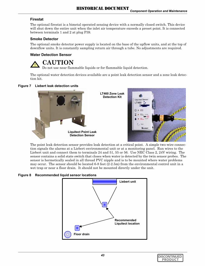
Component Operation and Maintenance
43
FirestatThe optional firestat is a bimetal operated sensing device with a normally closed switch. This device will shut down the entire unit when the inlet air temperature exceeds a preset point. It is connected between terminals 1 and 2 at plug P39.
Smoke DetectorThe optional smoke detector power supply is located on the base of the upflow units, and at the top of downflow units. It is constantly sampling return air through a tube. No adjustments are required.
Water Detection Sensor
The optional water detection devices available are a point leak detection sensor and a zone leak detec-tion kit.
Figure 7 Liebert leak detection units
The point leak detection sensor provides leak detection at a critical point. A simple two-wire connec-tion signals the alarms at a Liebert environmental unit or at a monitoring panel. Run wires to the Liebert unit and connect them to terminals 24 and 51, 55 or 56. Use NEC Class 2, 24V wiring. The sensor contains a solid state switch that closes when water is detected by the twin sensor probes. The sensor is hermetically sealed in all thread PVC nipple and is to be mounted where water problems may occur. The sensor should be located 6-8 feet (2-2.5m) from the environmental control unit in a wet trap or near a floor drain. It should not be mounted directly under the unit.
Figure 8 Recommended liquid sensor locations
! CAUTIONDo not use near flammable liquids or for flammable liquid detection.
Liquitect Point Leak Detection Sensor
LT460 Zone Leak Detection Kit
RecommendedLiquitect location
Liebert unit
Floor drain
DISCONTINUED PRODUCT
HISTORICAL DOCUMENT

Component Operation and Maintenance
44
The zone leak detection kit provides leak detection for a defined zone. This kit is ideal for perimeter sensing or serpentine coverage of small areas. A simple, two-wire connection signals the alarms at a Liebert environmental unit or at a monitoring panel. Run wires to the Liebert unit and connect them to terminals 24 and 51, 55 or 56. The sensor utilizes Liebert's LT500Y leak detection cable. The kit is offered with five different lengths of cable sized specifically for the type of Liebert Environmental unit (see matrix below). Refer to matrix below for the recommended location of leak detection cable.
Remote ShutdownA connection point is provided for customer supplied remote shutdown devices. This terminal strip is located at the top of upflow units, and at the base of downflow units. Terminals 37 and 38 on the ter-minal strip are jumpered when no remote shutdown device is installed.
6.2 FiltersFilters are usually the most neglected item in an environmental control system. To maintain efficient operation, they should be checked monthly and changed as required. Because replacement intervals vary with environmental condition and filter type, each unit is equipped with a filter clog switch. This warns of restricted airflow through the filter compartment by activating the Change Filter alarm.
Turn power off before replacing filters.
Challenger 3000 filters are 28-1/2" by 29-1/2", either 2" or 4" thick, plus an optional 2" thick pre-filter. The filter is replaced from the front of the unit. On upflow units, the filter is vertical, in front of the lower compartment. Pull the filter out toward you to remove it. On downflow units, the filter is hori-zontal, above the electrical panel. Slide the filter out toward you to remove it.
After replacing the filter(s), test the operation of the filter clog switch. Turn the adjusting screw counter clockwise to trip the switch — this will energize the Change Filter alarm. To adjust the switch proceed as follows: With the fan running, set the switch to energize the light with clean filters. The unit panels must all be in place and closed to accurately find this point. Then turn the adjusting knob one turn clockwise, or to the desired filter change point.
Table 16 Zone leak detection kit installation scenariosScenarios
Upflow UnitDetection around
entire unit
Upflow UnitDetection on sides
andin front of unit
Downflow UnitDetection around
entire unit
Downflow UnitDetection on sides
andin front of unit
Distance From Unit
Distance:In back
On sidesIn front
2 ft2 ft2 ft
No cable behind2 ft2 ft
1 ft1 ft6 ft
No cable behind1 ft6 ft
Unit(footprint-
in.)
Part Number
Challenger
(32.5 x 32.5)
LT460-Z30 LT460-Z20 LT460-Z30 LT460-Z25
2-ft clearance in front
2-ft clearance in front 6-ft clearance
in front6-ft clearance
in front
DISCONTINUED PRODUCT
HISTORICAL DOCUMENT
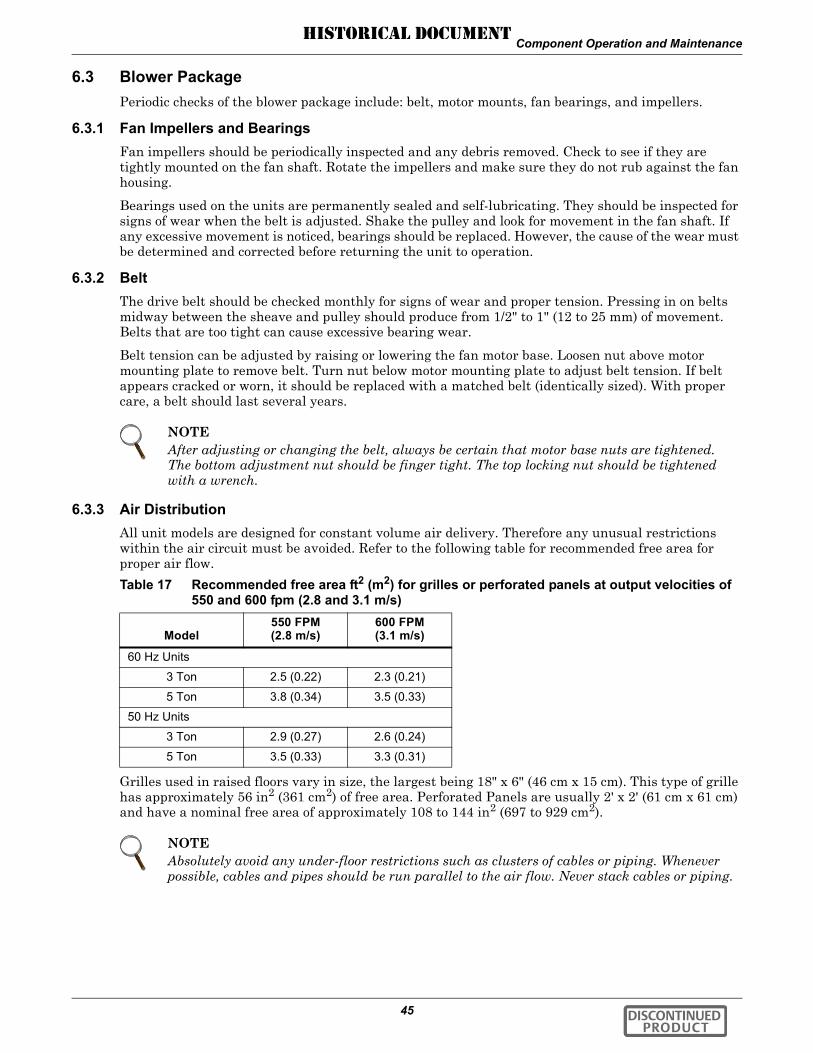
Component Operation and Maintenance
45
6.3 Blower PackagePeriodic checks of the blower package include: belt, motor mounts, fan bearings, and impellers.
6.3.1 Fan Impellers and BearingsFan impellers should be periodically inspected and any debris removed. Check to see if they are tightly mounted on the fan shaft. Rotate the impellers and make sure they do not rub against the fan housing.
Bearings used on the units are permanently sealed and self-lubricating. They should be inspected for signs of wear when the belt is adjusted. Shake the pulley and look for movement in the fan shaft. If any excessive movement is noticed, bearings should be replaced. However, the cause of the wear must be determined and corrected before returning the unit to operation.
6.3.2 BeltThe drive belt should be checked monthly for signs of wear and proper tension. Pressing in on belts midway between the sheave and pulley should produce from 1/2" to 1" (12 to 25 mm) of movement. Belts that are too tight can cause excessive bearing wear.
Belt tension can be adjusted by raising or lowering the fan motor base. Loosen nut above motor mounting plate to remove belt. Turn nut below motor mounting plate to adjust belt tension. If belt appears cracked or worn, it should be replaced with a matched belt (identically sized). With proper care, a belt should last several years.
6.3.3 Air DistributionAll unit models are designed for constant volume air delivery. Therefore any unusual restrictions within the air circuit must be avoided. Refer to the following table for recommended free area for proper air flow.
Grilles used in raised floors vary in size, the largest being 18" x 6" (46 cm x 15 cm). This type of grille has approximately 56 in2 (361 cm2) of free area. Perforated Panels are usually 2' x 2' (61 cm x 61 cm) and have a nominal free area of approximately 108 to 144 in2 (697 to 929 cm2).
NOTEAfter adjusting or changing the belt, always be certain that motor base nuts are tightened. The bottom adjustment nut should be finger tight. The top locking nut should be tightened with a wrench.
Table 17 Recommended free area ft2 (m2) for grilles or perforated panels at output velocities of 550 and 600 fpm (2.8 and 3.1 m/s)
Model550 FPM(2.8 m/s)
600 FPM(3.1 m/s)
60 Hz Units
3 Ton 2.5 (0.22) 2.3 (0.21)
5 Ton 3.8 (0.34) 3.5 (0.33)
50 Hz Units
3 Ton 2.9 (0.27) 2.6 (0.24)
5 Ton 3.5 (0.33) 3.3 (0.31)
NOTEAbsolutely avoid any under-floor restrictions such as clusters of cables or piping. Whenever possible, cables and pipes should be run parallel to the air flow. Never stack cables or piping.
DISCONTINUED PRODUCT
HISTORICAL DOCUMENT

Component Operation and Maintenance
46
6.4 Refrigeration SystemEach month, the components of the refrigeration system should be inspected for proper function and signs of wear. Since, in most cases, evidence of malfunction is present prior to component failure, peri-odic inspections can be a major factor in the prevention of most system failures.
Refrigerant lines must be properly supported and not allowed to vibrate against ceilings, floors or the unit frame. Inspect all refrigerant lines every six months for signs of wear and proper support. Also inspect capillary and equalizer lines from the expansion valve and support as necessary.
Each liquid line has a sight glass that indicates liquid refrigerant flow and the presence of moisture. Bubbles in the sight glass indicate a shortage of refrigerant or a restriction in the liquid line. The moisture indicator changes from green to yellow when moisture is present in the system.
6.4.1 Suction PressureSuction pressure will vary with load conditions. The low pressure switch will shut the compressor down if suction pressure falls below the cut-out setting. High suction pressure reduces the ability of the refrigerant to cool compressor components and can result in compressor damage. Minimum (pres-sure switch cut-out setting) and maximum (design operating) suction pressures are in Table 18.
6.4.2 Discharge PressureDischarge Pressure can be increased or decreased by load conditions or condenser efficiency. The high pressure switch will shut the compressor down at its cut-out setting. Refer to Table 19, below.
6.4.3 SuperheatSuperheat can be adjusted by the Thermostatic Expansion Value (TEV). To determine superheat:
1. Measure the temperature of the suction line at the point the TEV bulb is clamped.2. Obtain the gauge pressure at the compressor suction valve.3. Add the estimated pressure drop between bulb location and suction valve.4. Convert the sum of the two pressures to the equivalent temperature.5. Subtract this temperature from the actual suction line temperature. The difference is superheat.
Table 18 Suction pressures
System
MinimumPSIG (kPa)
R–22
MaximumPSIG (kPa)
R–22
Air w/FSC(Fan Speed Control)
15 (103) 90 (620)
Air w/Lee-Temp Control(Floodback head pressure control)
20 (137) 90 (620)
Water Cooled 20 (137) 90 (620)
Glycol Cooled 20 (137) 90 (620)
Table 19 Discharge pressures
System DesignDischarge Pressure
PSIG (kPa)
Air Cooled 260 (1795)
Water/Glycol Cooled 65-75°F (18-24°C) fluid 210 (1450)
85°F (29°C) fluid 225 (1550)
115°F (46°C) fluid 295 (2035)
Maximum 330 (2275)
High Pressure Cut-Out 360 (2482)
DISCONTINUED PRODUCT
HISTORICAL DOCUMENT

Component Operation and Maintenance
47
6.4.4 Thermostatic Expansion Valve
OperationThe thermostatic expansion valve performs one function. It keeps the evaporator supplied with enough refrigerant to satisfy load conditions. It does not effect compressor operation.
Proper valve operation can be determined by measuring superheat. If too little refrigerant is being fed to the evaporator, the superheat will be high; if too much refrigerant is being supplied, the superheat will be low. The correct superheat setting is between 10 and 15°F (5.6 and 8.3°C).
AdjustmentTo adjust the superheat setting, proceed as follows:
1. Remove the valve cap at the bottom of the valve.2. Turn the adjusting stem counterclockwise to lower the superheat.3. Turn the adjusting stem clockwise to increase the superheat.
6.4.5 Hot Gas Bypass Valve
OperationThe hot gas bypass is inserted between the compressor discharge line and the leaving side of the expansion valve through the side outlet distributor. The system, with normal operation when the evaporator is under full load, will maintain enough pressure on the leaving side of the hot gas valve to keep the valve port closed.
If the load on the evaporator decreases, the evaporator will get colder. When the coil is too cold, the internal pressure in the evaporator drops and allows the hot gas bypass valve to open. Hot gas then mixes with the liquid coolant on the discharge side of the expansion valve raising the temperature and pressure in the evaporator. The net result is a reduction in the cooling capacity of the unit to match the load.
To aid in lubricating the compressor, the hot gas bypass solenoid is delayed for 30 seconds on the ini-tial call for cooling and de-energized for 30 seconds during every 60 minutes of continuous operation.
AdjustmentUpon deciding what evaporator temperature is desired, the following procedure should be used to adjust the hot gas bypass valve:
1. Install the suction and discharge pressure gauge.2. Adjust the temperature setpoint to call for cooling so that the refrigeration compressor will run.3. Remove the TOP adjusting nut from the valve.4. Insert an Allen wrench in the brass hole at top of the valve in adjusting port, and turn
CLOCKWISE if a higher evaporator temperature is required.5. After obtaining the suction pressure required, reinstall the cap tightly making sure there are no
leaks.6. Let the evaporator operate for approximately 10 to 15 minutes to make sure the suction pressure
is within the desired range.7. There will be a fluctuation of approximately 3 to 6 PSIG (21 to 41 kPa) on the evaporator due to
the differential on the hot gas bypass.8. Return the temperature setpoint to desired number.
NOTEMake no more than one turn of the stem at a time. As long as 30 minutes may be required for the new balance to take place.
DISCONTINUED PRODUCT
HISTORICAL DOCUMENT

Component Operation and Maintenance
48
6.4.6 Air Cooled CondenserRestricted airflow through the condenser coil will reduce the operating efficiency of the unit and can result in high compressor head pressure and loss of cooling.
Clean the condenser coil of all debris that will inhibit air flow. This can be done with compressed air or commercial coil cleaner. Check for bent or damaged coil fins and repair as necessary. In winter, do not permit snow to accumulate around the sides or underneath the condenser.
Check all refrigerant lines and capillaries for vibration isolation. Support as necessary. Visually inspect all refrigerant lines for signs of oil leaks.
Checking Refrigerant Charge (Lee–Temp/Flood Back Head Pressure Control)The system refrigerant level must be checked periodically. To do so:
1. Adjust temperature setpoint in the unit so that the compressor will run continuously.2. The refrigerant level is visible through two sight glasses on the receiver and will vary with
ambient temperature. a. 40°F (4.4°C) and lower — Midway on the bottom sight glass. b. 40 to 60°F (4.4 to 15.6°C) — Bottom sight glass should be clear with liquid. c. 60°F (15.6°C) and above — Midway on the top sight glass.
3. Return temperature setpoint to desired number.
Figure 9 Outdoor fan/condenser configuration
Secure each leg to condenser frame at all points shown using hardware provided.
Liquid line
* B
Hot gas line
Electric service supplied by others
FAN SPEED CONDENSER
Lee-Temp heater pad connection box
*B - Inverted traps are to be field-supplied and installed (typ). When installing traps, provide clearance for swing end of access door. Traps are to extend above base of coil by aminimum of 7-1/2" (190 mm).
Liquid line
Electricservicesupplied by others
Hot gas line
* B
LEE-TEMP CONDENSER
DISCONTINUED PRODUCT
HISTORICAL DOCUMENT

Component Operation and Maintenance
49
6.4.7 Water/Glycol Cooled Condensers
Coaxial CondenserEach water or glycol cooled module has a coaxial condenser which consists of a steel outside tube and a copper inside tube.
Coaxial condensers do not normally require maintenance or replacement if the water supply is clean. If your system operates at high head pressure with reduced capacity, and all other causes have been eliminated, the coaxial condenser may be obstructed and needs to be replaced.
Regulating ValveThe water regulating valve automatically regulates the amount of fluid necessary to remove the heat from the refrigeration system, permitting more fluid to flow when load conditions are high and less fluid to flow when load conditions are low. The valve consists of a brass body, balance spring, valve seat, valve disc holders, capillary tube to discharge pressure, and adjusting screw.
Standard Valve - 150 psig (1034 kPa) system for 3 & 5 ton units (Johnson Controls Valve)High Pressure Valve - 350 psig (2413 kPa) system for 5 ton units (Johnson Controls Valve)Adjustment—The valve may be adjusted with a standard refrigeration service valve wrench or screw driver. Refer to Table 19 for recommended refrigerant pressures.
To lower the head pressure setting, turn the square adjusting screw clockwise until the high pressure gauge indicates the desired setting.
To raise the head pressure setting, turn the adjusting screw counterclockwise until the desired set-ting is obtained.
Figure 10 Johnson Controls valve adjustment
Manual Flushing—The valve may be flushed by inserting a screwdriver or similar tool under the two sides of the main spring and lifting. This action will open the valve seat and flush any dirt parti-cles from the seat. If this fails, it will be necessary to disassemble the valve and clean the seat.
Range Spring
Valve Spring Guide
Top Retainer
Range Adjustment Screw
Insert screwdrivers under the valve spring guide.
DISCONTINUED PRODUCT
HISTORICAL DOCUMENT

Component Operation and Maintenance
50
High Pressure Valve - 350 PSIG System (2413 kPa) for 3 Ton Units (Metrex Valve)Adjustment—The valve may be adjusted using a 1/8" diameter rod. Turn adjusting collar nut coun-terclockwise to raise head pressure. Turn it clockwise to lower head pressure. Rotation directions are as viewed from top of valve spring housing.
Figure 11 Metrex valve adjustment
Manual Flushing—The valve may be flushed by rotating the socket head screw clockwise. This screw must be in the OUT position (counterclockwise) for normal valve operation.
Valve Disassembly
1. Shut off the water supply by using isolating valves.2. Relieve the tension on the main spring by turning the adjusting screw (or collar) as far as it will
go (provide a container to catch water below the valve).3. Remove four screws extending through the main spring housing.4. Remove the center assembly screws for access to all internal parts.5. Clean the seat if possible. If the seat is pitted or damaged, replace the valve rubber disc and valve
seat.6. After valve is reassembled check for leaks.7. Readjust head pressure control.
Testing Function of Valve—When the refrigeration system has been off for approximately 10 to 15 minutes, the water flow should stop.
If the water continues to flow, the valve is either improperly adjusted (with head pressure too low) or the pressure sensing capillary is not connected properly to the condenser.
Glycol Solution MaintenanceIt is difficult to establish a specific schedule of inhibitor maintenance since the rate of inhibitor deple-tion depends upon local water conditions. Analysis of water samples at time of installation and every six months should help to establish a pattern of depletion. A visual inspection of the solution and fil-ter residue is often helpful in judging whether or not active corrosion is occurring.
The complexity of water caused problems and their correction makes it important to obtain the advice of a water treatment specialist and follow a regularly scheduled maintenance program. It is impor-tant to note that improper use of water treatment chemicals can cause problems more serious than using none.
Proper inhibitor maintenance must be performed in order to prevent corrosion of the glycol system. Consult glycol manufacturer for testing and maintenance of inhibitors. Do not mix products from dif-ferent manufacturers. For further details, refer to filling instructions in the installation manual, Lie-bert part number SL-11925.
Adjusting Collar Nut
DISCONTINUED PRODUCT
HISTORICAL DOCUMENT
Component Operation and Maintenance
51
6.4.8 Compressor Functional CheckThe following diagnostic procedure should be used to evaluate whether the compressor is working properly.
1. Proper voltage to the unit should be verified.2. The normal checks of motor winding continuity and short to ground should be made to determine
if the inherent overload motor protector has opened or if an internal motor short or ground fault has developed. If the protector has opened, the compressor must be allowed to cool sufficiently to allow it to reset.
3. Proper indoor and outdoor blower/fan operation should be verified. Condenser glycol flow should be verified.
4. With service gauges connected to suction and discharge pressure fittings, turn on the compressor. If suction pressure falls below normal levels, the system is either low on charge or there is a flow blockage in the system.
5. If suction pressure does not drop and discharge pressure does not rise to normal levels, reverse any two of the compressor power leads and reapply power to make sure compressor was not wired to run in reverse direction. If pressures still do not move to normal values, system is properly charged and solenoid valves function, the compressor is faulty. Reconnect the compressor leads as originally configured and use normal diagnostic procedures to check operation of the reversing valve.
6. To test if the compressor is pumping properly, the compressor current draw must be compared to published compressor performance curves using the operating pressures and voltage of the system. If the measured average current deviates more than ±15% from published values, a faulty compressor may be indicated. A current imbalance exceeding 15% of the average on the three phases should be investigated further.
7. Before replacing or returning a compressor: Be certain that the compressor is actually defective. At a minimum, recheck a compressor returned from the field in the shop or depot for Hipot, winding resistance and ability to start before returning. More than one-third of compressors returned for warranty analysis are determined to have nothing wrong. They were misdiagnosed in the field as being defective. Replacing working compressors unnecessarily costs everyone.
6.4.9 Compressor ReplacementInfrequently a fault in the motor insulation may result in a motor burn, but burnouts rarely occur in a properly installed system. Of those that do, most are the effects of mechanical or lubrication fail-ures, resulting in the burnout as a secondary consequence.
If problems that can cause compressor failures are detected and corrected early, a large percentage can be prevented. Periodic maintenance inspections by alert service personnel on the lookout for abnormal operation can be a major factor in reducing maintenance costs. It is easier and far less costly to take the steps necessary to ensure proper system operation than it is to allow a compressor to fail and require replacement.
When troubleshooting a compressor, check all electrical components for proper operation.
1. Check all fuses and circuit breakers.2. Check Hi-Lo Pressure switch operation.3. If a compressor failure has occurred, determine whether it is an electrical or mechanical failure.
Mechanical FailureA mechanical compressor failure will be not be indicated by a burned odor. The motor will attempt to run. If you have determined that a mechanical failure has occurred, the compressor must be replaced.
If a burnout does occur, correct the problem that caused the burnout and clean the system. It is important to note that successive burnouts of the same system are usually caused by improper clean-ing.
DISCONTINUED PRODUCT
HISTORICAL DOCUMENT

Component Operation and Maintenance
52
Electrical FailureAn electrical failure will be indicated by a distinct pungent odor. If a severe burnout has occurred, the oil will be black and acidic.
In the event that there is an electrical failure and a complete burnout of the refrigeration compressor motor, the proper procedures must be performed in order to clean the system to remove any acids that would cause a future failure.
There are two kits that can be used with a complete compressor burnout - Sporlan System Cleaner and Alco Dri-Kleener. Follow the manufacturer's procedure.
Compressor Replacement ProcedureReplacement compressors are available from your Liebert supplier. They will be shipped in a reusable crate to the job site as required by the service contractor.
Upon shipping a replacement compressor, the service contractor will be billed in full for the compres-sor until the replacement has been returned to the factory.
The compressor should be returned in the same container used for shipping to the job. The possible damage causes or conditions that were found should be recorded by marking the compressor return tag.
1. Disconnect power.2. Attach suction and discharge gauges to access fittings.3. Recover refrigerant using standard recovery procedures and equipment. Use a filter-drier when
charging the system with recovered refrigerant.
4. Front seat service valves to isolate the compressor. Reclaim charge from compressor.5. Remove service valves, pressure switch capillaries, and disconnect all electrical connections.6. Remove failed compressor.
7. Install replacement compressor and make all connections.8. Pressurize and leak test the system at approximately 150 PSIG (1034 kPa) pressure.9. Follow manufacturer's instructions for clean-out kits.10. Follow charging instructions as stated in the installation manual, Liebert part number SL-11925.
! CAUTIONDamage to a replacement compressor caused by improper system cleaning constitutes abuse under the terms of the warranty, and the WARRANTY WILL BE VOID.
! CAUTIONAvoid touching or contacting the gas and oils with exposed skin. Severe burns will result. Use long rubber gloves in handling contaminated parts.
! CAUTIONDo not loosen any refrigeration or electrical connections before relieving pressure.
NOTERelease of refrigerant to the atmosphere is harmful to the environment and is unlawful. Refrigerant must be recycled or discarded in accordance with federal, state, and local regulations.
! CAUTIONA scroll compressor must rotate in the proper direction. Record compressor motor connections when removing failed compressor. Wire the replacement compressor motor the same way to maintain proper rotation direction.
DISCONTINUED PRODUCT
HISTORICAL DOCUMENT

Component Operation and Maintenance
53
6.5 Humidifier
6.5.1 Infrared HumidifierDuring normal humidifier operation, deposits of mineral solids will collect in the humidifier pan. This should be cleaned out periodically to ensure efficient operation. Each water supply has different char-acteristics, so the time interval between cleanings must be determined locally. A monthly check (and cleaning if necessary) is recommended.
Removing the PanTo remove humidifier pan, first open disconnect switch and open front panel. Allow time for pan and water to cool. Unlatch front retainer clip (or remove screw from bracket on some units). Pull pan for-ward. Remove stand pipe to allow pan to drain. Disconnect drain line. Pull pan forward to remove it.
Cleaning the PanAn autoflush system can greatly increase the time between cleanings but does not eliminate the need for periodic checks and maintenance.
Scale on the side and bottom can be loosened with a stiff brush. Flush with water and replace pan in humidifier.
Changing Humidifier Lamps1. Open disconnect switch.2. Open front panel.3. Remove screws securing line voltage compartment cover, then remove the cover.4. In line voltage compartment, disconnect one end of the purple jumpers, then locate the burned out
bulb with a continuity meter.5. Remove humidifier pan. Refer to Removing the Pan on page 53.6. Remove lamp brackets (2) under lamps.
Figure 12 Infrared humidifier lamps
7. Loosen two screws securing bulb wires to junction block.8. Pull bulb straight down.9. Replace bulb. Wrap wires once loosely around bulb. This will support the bulb and also allow for
thermal expansion. Make sure lamp wires are secure in the junction block.
10. Reverse Steps 1 through 6 to reassemble.
! CAUTIONBefore removing pan, be sure power to unit is disconnected and water in the humidifier pan is no hotter than lukewarm.
! CAUTIONDo not touch the quartz lamps with your bare hands. Oily deposits such as fingerprints will severely shorten bulb life. Use clean cotton gloves at all times.
Humidifier Lamps
DISCONTINUED PRODUCT
HISTORICAL DOCUMENT

Component Operation and Maintenance
54
Autoflush Infrared Humidifier Cleaning System
The autoflush system will periodically flush the humidifier pan with water to prevent the buildup of water minerals due to saturation. Because water conditions vary, the amount of water flushing through the system may be programmed to match local needs.
Water amounts between 110% and 500% of the amount needed for humidification may be selected. Operation of the flushing system is then automatic and no further adjustments need to be made.
Autoflush OperationThe operation of the autoflush is divided into four steps, beginning with a call for humidification.
1. If the humidifier has not been activated for over 30 hours, the autoflush will flow water into the pan for about 30 seconds. This will provide a minimum amount of water in the pan and prevent heat damage to the humidifier pan. Humidifier lamps are OFF.
2. If the humidifier has been activated within the last 30 hours, Step 1 is bypassed. The autoflush will flow water into the pan for about 4 minutes. The humidifier lamps are on and the humidifier is operational during this period. When the pan is filled (the fill cycle has timed out), the water make-up valve is closed.
3. The water make-up valve remains OFF and the humidifier lamps are ON for a maximum of 9-1/2 minutes.
4. After the 9-1/2 minute delay, the autoflush adds water to the pan to replenish the water used in humidification and flush the pan of mineral solids. This amount of water is adjustable from 110% to 500% in increments of 10%. At the end of this cycle, the make-up valve is closed. Steps 3 and 4 repeat as long as humidification is required.
Autoflush ControlsUse the LCD display, menu, and keys on the front control panel to program the autoflush controls.
6.5.2 Steam Generating HumidifierSteam generating humidifiers are designed to operate in voltage ranges from 200 to 575 volts and generate 11 pounds (5 kg) of steam per hour. These humidifiers operate efficiently over a wide range of water quality conditions and automatically adjust to changes in the conductivity of water. The humidifiers drain and refill to maintain an amperage setpoint and alert the operator when the humidifier canister needs to be replaced. The humidifier is in the lower section of upflow units; it is in the middle section of downflow units.
Figure 13 Steam generating humidifier
NOTETo operate properly, the Autoflush Humidifier requires a water source that can deliver at least 1 gpm (0.063 l/s) with a minimum pressure of 20 psig (138 kPa).
DISCONTINUED PRODUCT
HISTORICAL DOCUMENT
Component Operation and Maintenance
55
Operation1. During start-up, when the humidity control calls for humidification, the fill valve opens and
allows water to enter the canister. When the water level reaches the electrodes, current flows and the water begins to warm. The canister fills until the amperage reaches the setpoint and the fill valve closes. As the water warms, its conductivity increases and the current flow, in turn, rises. If the amperage reaches 115% of the normal operating amperage, the drain valve opens and flushes some of the water out of the canister. This reduces electrode contact with the water and lowers the current flow to the amperage setpoint. Boiling soon commences, and the canister operates normally.
2. If the conductivity of the water is low, the canister fills and the water level reaches the canister full electrode before the amperage setpoint is reached. The humidifier stops filling to prevent overflow. Boiling should commence in time. As water is boiled off, the mineral concentration in the canister increases and current flow also increases. The canister eventually reaches full output and goes to normal operation. No drain is permitted until then.
3. When full output is reached the circuit board starts a time cycle which is factory set at 60 seconds. During this repeating time cycle, the fill valve will open periodically to replenish the water being boiled off and maintain a “steady state” output at the set point. The amperage variance will depend on the conductivity of the water.
4. After a period of time, the mineral concentration in the canister becomes too high. When this occurs, the water boils too quickly. As the water quickly boils off and less of the electrode is exposed, the current flow decreases. When the current crosses the low threshold point (factory set at 90%) before the end of the time cycle, the drain valve opens, draining the mineral laden water out and replacing it with fresh water. This lowers the mineral concentration and returns the canister to “steady state” operation and prolongs canister life. The frequency of drains depends on water conductivity.
5. Over a period of time, the electrode surface will become coated with a layer of insulating material, which causes a drop in current flow. As this happens, the water level in the canister will slowly rise exposing new electrode surface to the water to maintain normal output. Eventually, the steady state water level will reach the canister full electrode and indicate so by activating the canister full alarm. At this point, all of electrode surface has been used up and the canister should be replaced.
6. After the entire electrode surface has been coated, the output will slowly begin to fall off. This usually occurs in the last several hours of electrode life and should allow enough time to schedule maintenance. During these last hours, the mineral concentration can increase. If the mineral concentration is too high, arcing can occur. If the electrodes start to arc, turn off the humidifier immediately and replace the canister with the identical part.
ControlsThe humidifier RUN/DRAIN switch is located at the upper right of the humidifier assembly. This switch should be in the RUN position when the humidifier is in normal operation, and in the DRAIN position when a manual drain sequence is required. The electronic control board for the humidifier is located on the right side of the humidifier assembly. When the main unit is energized, power is avail-able to the humidifier circuits.
DISCONTINUED PRODUCT
HISTORICAL DOCUMENT

Component Operation and Maintenance
56
Replacing the CanisterOver a period of operation, the humidifier electrodes become coated with mineral solids. This coating insulates the electrodes and decreases the current flow. To maintain humidifier capacity, the water level slowly rises to expose fresh electrode. Eventually, the entire electrode becomes coated and the water level reaches the top. At this point, the canister full alarm is activated and the output begins to fall. When this happens, it is necessary to replace the full canister.
To replace the canister:
1. Turn off the humidifier by lowering the humidity setpoint below the ambient humidity level. Record the original setpoint.
2. Place the RUN/DRAIN switch in the DRAIN position to drain the water from the canister.3. Return the RUN/DRAIN switch to the RUN position after the canister has drained.
4. Turn OFF the power at the main unit.5. Remove the cover from the humidifier cabinet.
6. Locate the power wires to the steam canister. They are connected to the canister with 1/4" quick connects. Make note of the wiring configuration before removing any wires. Refer to the schematic on the unit. Slide the rubber boot back to expose the connections. Remove the three power wires and the two canister full wires. Do not loosen the screws that secure the electrodes.
7. Loosen the steam outlet hose clamp and slide the steam hose away from the canister top fitting.8. The canister is now ready to be removed. Pull the canister straight up and out of the cabinet
toward you.9. Replace the canister with the part indicated in Table 20.
10. Replace the canister by reversing the above procedure. Make special note of the following:
! WARNINGTo avoid a shock hazard, all power to the unit must be disconnected before proceeding with the canister replacement procedure.
! CAUTIONThe canister and steam hose may be hot! Allow time for the humidifier to cool before replacing parts.
Table 20 Humidifier canister part numbersPart
Number VoltageCapacity
lbs/hr (kg/hr)
136798P1 200-460* 11 (5)
136798P2 380-575 11 (5)* Can operate on 575 V unit with transformer
NOTEWhen replacing the canister:
1. Make sure the two “O” rings are lubricated and properly seated on the bottom neck.2. Always check the fill and drain solenoids for proper operation.
NOTEWhen replacing the wiring, connect the red wire from terminal #1 on the interface to the red top terminal on the canister. It is in the middle of a group of three terminals. The black wire from terminal #2 on the interface connects to the power terminal farthest from the red terminal/wire. The power wire to this terminal is routed through the current sensing coil.
DISCONTINUED PRODUCT
HISTORICAL DOCUMENT

Component Operation and Maintenance
57
Figure 14 Canister replacement
Circuit Board Adjustments
Humidifier operation is governed by the humidifier control board. This board is located on the right side of the humidifier compartment. There are three potentiometers mounted on the board. These pots can be used to adjust for extreme water conductivity conditions and capacity.
The “%” pot controls the amperage at which the drain will energize. The pot is clearly marked in per-centages. This adjustment is factory set at 90%, which indicates that the unit will drain when the amperage falls off to 90% of the capacity setpoint. Raising the value increases the frequency of drain cycles. Lowering the value decreases the frequency of drain cycles. The frequency should be increased for highly conductive water and decreased for less conductive water. If adjustment is necessary, and a change of three to four percent in either direction does not permit normal operation of the unit, con-sult your Liebert supplier.
The pot marked “SEC” controls the duration of the drain cycle. The pot is clearly marked in seconds. This adjustment is factory set at 60 seconds and should not be readjusted without consulting your Liebert supplier.
The pot marked “CAP ADJ” is factory set at 100%. The maximum capacity is determined by a fixed resistor (R4) which is factory selected based on unit voltage.
Drain Tempering FeatureAll units are equipped with a drain tempering feature which mixes cold fill water with hot drain water to protect drain piping. This feature can lower drain water temperature to as low as 140°F (60°C), depending on water pressure. To deactivate this feature, remove the diode from socket CR18 on the circuit board (lower left, above LED).
! WARNINGCircuit board adjustment should be performed by qualified personnel only. Hazardous voltages are present in the equipment throughout the procedure. Use extreme caution. If desired, power may be disconnected prior to the procedure.
DISCONTINUED PRODUCT
HISTORICAL DOCUMENT

Troubleshooting
58
7.0 TROUBLESHOOTING
Use this section to assist in troubleshooting your unit. Also refer to 5.0 - Alarm Descriptions. Sug-gestions are grouped by product function for convenience.
! WARNINGOnly qualified personnel should perform service on these units. Lethal voltage is present in some circuits. Use caution when troubleshooting with power on. Disconnect and lock out power before replacing components. Use caution and standard procedures when working with pressurized pipes and tubes.
! CAUTIONWhen using jumpers for troubleshooting, always remove jumpers when maintenance is complete. Jumpers left connected could override controls and cause equipment damage.
Table 21 Blower troubleshootingSymptom Possible Cause Check or Remedy
Blower will not startNo main power Check L1, L2 and L3 for rated voltage.
Blown fuse or tripped circuit breaker (CB) Check fuses or CBs to main fan.
Overloads tripped Push reset button on main fan overload. Check amp draw.
No output voltage from transformer Check for 24 VAC between P24-2 and P24-1. If no voltage, check primary voltage.
Control fuse blown or circuit breaker tripped Check for 24 VAC between P4-4 and E1. If no voltage, check for short. Replace fuse or reset circuit breaker.
Table 22 Chilled water troubleshootingSymptom Possible Cause Check or Remedy
Chilled water or hot water/steam valve not opening
Motor operates but valve won’t open Check linkage for adjustment and be sure that it is tight on the valve.
Modulating MotorsNo 24 VAC power to motor Check linkage for adjustment and be sure that it is
tight on the valve.
No signal from control Check DC voltage on printed circuit board in motor. Terminal No. 1 is grounded and No. 3 is positive. DC voltage should vary from 0.8 to 2.0 VDC or above as temperature control is varied below room temperature on cooling valve or above room temperature on heating valve.
Motor not working Remove wires on terminal No. 1 and No. 3 from the motor (do not short). With 24 VAC power from TR to TR jumper terminal 1 and 2 on motor to drive open. Remove jumper to drive closed, if motor fails to work, replace it.
Actuator Motors No 24 VAC power to motor Check for 24 VAC between P22-3 and P22-5 (open), or P22-1 and P22-5 (closed).
DISCONTINUED PRODUCT
HISTORICAL DOCUMENT

Troubleshooting
59
Table 23 Compressor and refrigeration system troubleshootingSymptom Possible Cause Check or Remedy
Compressor will not startPower off Check main switch, fuses or CBs and
wiring
Current overload open Re-set units with overload option manually. Allow compressor to cool for internal overloads to reset.
Loose electrical connections Tighten connections
Compressor motor burned out Check and replace compressor if defective.
Compressor will not operate, contactor not pulling in
No call for cooling Check monitor status.
Solenoid valve not energizing Hold screwdriver over solenoid and check for magnetic field. This indicates solenoid is energized.
Low pressure switch not making contact Check gas pressure - manually energize low pressure switch.
Compressor will not operate, contact not pulling in
High pressure switch open Reset switch. Refer to other refrigeration troubleshooting suggestions.
Compressor contactor pulled in but compressor will not operate
Blown fuse or tripped CB Check for line voltage after fuses or CBs, and after contactors.
Compressor runs for three minutes then stops; contactor drops out.
Low pressure switch not closing Check for low gas pressure. Compressor is running on Positive Start Kit (air cooled systems only)
Liquid line solenoid valve not opening Check magnetic field to see if energized.
High discharge pressureDirty condenser or drycooler fins Clean coil.
Condenser equipment not operating Check operation.
High refrigerant charge Check refrigerant charge.
Hot gas bypass valve adjusted improperly
Adjust properly.
Water regulating valve adjusted improperly
Adjust properly.
Low discharge pressureExcessive fluid flow through condenser Adjust fluid regulating valve
Suction service valve partially closed Open the valve.
Faulty head pressure control valve or condenser fan speed control
Replace if defective.
Compressor rotation in reverse direction Check for proper power phase wiring to unit and to compressor motor.
Low suction pressureInsufficient refrigerant in system Check for leaks, repair, and add
refrigerant for air cooled. Evacuate and recharge for water/glycol unit.
Dirty air filters Change filters.
Plugged filter-drier Replace filter.
Improper superheat adjustment Reset expansion valve for 10-15°F (6-8°C)
Defective expansion valve sensing element
Replace element
Poor air distribution Check duct work for closed dampers. Check for under-floor restrictions at or near the unit.
Low condensing pressure Check head pressure control device.
Slipping belts Inspect and adjust
DISCONTINUED PRODUCT
HISTORICAL DOCUMENT

Troubleshooting
60
FloodingDefective or improperly set expansion valve
Increase superheat or replace valve
Evaporator fan motor or belt Correct problem or replace fan motor and/or belts.
Low condensing pressure Check head pressure control device
Slipping belts Inspect and adjust
Low compressor capacity or inability to pull down system
Compressor rotation in reverse direction.
Check for proper power phase wiring to unit and to compressor motor.
Leaking liquid line solenoid valve or dirt in valve
Replace valve if clean; clean out valve if dirty.
Compressor noisy Loose compressor or piping support Tighten clamps.
Pipe rattle Loose pipe connections Check pipe connections
Compressor running hotCompression ratio too high Check setting of high and low pressure
switches. Check condenser -- is it plugged? Check that all evaporator and condenser fans are operating properly.
Compressor cycles intermittentlyLow-pressure switch erratic in operation Check tubing to switch to see if clogged or
crimped. Check for proper switch operation.
Insufficient refrigerant in system Check for leaks, fix, and add refrigerant on air cooled unit. Evacuate and recharge water/glycol unit.
Suction service valve closed Open valve.
Insufficient fluid flowing through condenser or clogged condenser, or dirty air cooled condenser coils
Adjust fluid regulating valve to condenser. Flush the condenser.
Discharge service valve not fully open Open valve
Compressor cycles continuallyFaulty low pressure switch Repair or replace.
Dirt or restriction in tubing to pressure stat
Check and clean tubing.
Defective liquid line solenoid valve Check valve and solenoid operator; replace if necessary.
Plugged filter-drier Replace filter.
Compressor motor protectors tripping or cycling
High discharge pressure Check for loss of condenser water or blocked condenser fan or coil.
Defective overload relay Replace.
High suction temperature Reduce suction temperature by expansion valve adjustment or provide desuperheating.
Loose power or control circuit wiring connection
Check all power and control circuit connections.
Defective motor Check for motor ground or short. Replace compressor, if either condition is found.
Compressor cycles on locked rotorLow line voltage Check line voltage and determine location
of voltage drop.
Compressor motor defective Check for motor winding short or ground.
Single phasing Check voltage across all 3 legs at contactor. Correct source problem.
Motor burnoutCheck control panel for welded contactor contacts or welded overload contacts
Replace defective components
Table 23 Compressor and refrigeration system troubleshooting (continued)Symptom Possible Cause Check or Remedy
DISCONTINUED PRODUCT
HISTORICAL DOCUMENT

Troubleshooting
61
Table 24 Dehumidification troubleshootingSymptom Possible Cause Check or Remedy
No dehumidificationControl not calling for dehumidification
Check monitor status.
Compressor contactor not pulling in See 6.4.8 - Compressor Functional Check and Table 23.
Compressor won't run; fuse blown or CB tripped
See 6.4.8 - Compressor Functional Check and Table 23. Check fuses or CBs and contacts. Check line voltage
Table 25 Glycol pump troubleshootingSymptom Possible Cause Check or Remedy
Suddenly stops pumping Clogged strainer or impeller Clean out debris.
Suddenly slow pumping Clogged impeller, diffuser, or line Clean out debris and use strainer.
Excessive leakage around the pump shaft while operating
Worn seal or packing Replace seal or packing.
Performance poorWorn impeller or seal Replace with new impeller or seal.
Suction lift too high Relocate pump closer to supply.
Motor not up to speed; low voltage Larger lead wires may be required. Check for proper line voltage (±10%).
Worn bearings Replace pump
Noisy operationWorn motor bearings Replace pump
Low discharge head Throttle discharge-improve suction conditions.
Debris lodged in impeller Remove cover and clean out.
Cavitating pumps Adjust system pressures.
Table 26 Infrared humidifier troubleshootingSymptom Possible Cause Check or Remedy
No humidificationHumidifier pan not filling Check water supply.
Check fill valve operation
Check drain stand pipe adjustment
Check for clogged waterline
Control not calling for humidity Check monitor status
Humidity contact not pulling in Check visually. If contact is made, check line voltage after contactor and fuses or CBs.
Check for open humidifier safety stat. Jumper between terminals P35-6 and P35-15. If contactor pulls in, replace safety. Remove jumper.
Humidifier bulb burned out Replace bulb. Loosen lead on old bulb. Trim excess lead length on new bulb to avoid shorts.
DISCONTINUED PRODUCT
HISTORICAL DOCUMENT

Troubleshooting
62
Table 27 Steam generating humidifier troubleshootingSymptom Possible Cause Check or Remedy
False canister full indication Foaming
Check drain valve to ensure that it drains freely. Check and replace if defective.
Check water supply. If commercially softened, reconnect to raw water supply. If connected to hot water reconnect to cold water.
Main 24 VAC fuse or circuit breaker trips
Shorts or loose connections Check the wiring connections of the 24 VAC circuit.
Faulty circuit board Replace the circuit board.
Main fuses blow approximately 15 seconds after unit is activated
Faulty solenoid Check for magnetic field at coil.
Conductivity too high Check amp draw of humidifier on startup. If it exceeds rated amps, increase setting of the % pot on the circuit board
Main fuses blow when drain valve is activated.
Mineral deposits obstruct drain valve Check drain valve for obstructions and clean if necessary.
Faulty solenoid Check for magnetic field at coil.
Faulty circuit board Replace circuit board.
Unit ON, humidifier will not operate Humidifier not receiving power
Verify that RUN/DRAIN switch is in the RUN position.
Check fuses or CBs and replace or reset if necessary.
Make sure molex connector is securely plugged into circuit board and that no wires are loose.
Contactor pulled in, but no water enters canister
No water available to unit Check external shut-off valves.
Clogged fill line strainer Clean or replace fill line strainer.
Wiring breaks or loose connections Check for faulty wiring and loose connections.
Faulty circuit board Replace circuit board.
Water enters canister, but canister full circuit activates at a low water level
Foaming Check drain valve and water supply.
Canister interface connections incorrect
Check connection on component plate in humidifier cabinet. Terminal #1 on the square block interface device must be connected to L2 of the power terminal block. L2 must also be connected to the electrode closest to the steam outlet port.
Verify that the red wire from terminal #2 on the interface connects to the red top terminal on the canister. This is the one farthest from the steam outlet port and is the high water sensor probe.
Full isolation has broken down
Remove red canister full wire from canister. If normal operation resumes, canister must be replaced. Remove the wire from terminal #3 on the interface. If normal operation resumes, canister full interface must be replaced.
Drain assembly not operating freely Check and replace coil or valve if necessary.
Faulty circuit board Replace circuit board
Canister fills but overflows Canister full circuit does not activate Check wiring of canister full interface. Replace circuit board.
DISCONTINUED PRODUCT
HISTORICAL DOCUMENT
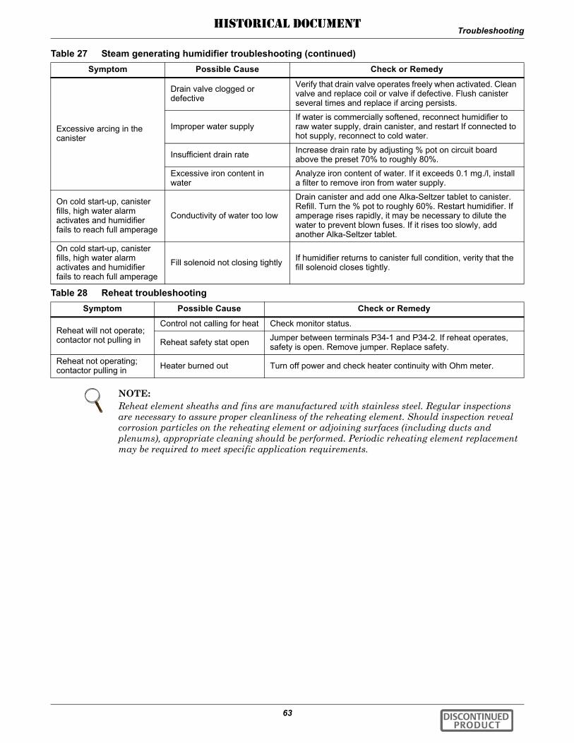
Troubleshooting
63
Excessive arcing in the canister
Drain valve clogged or defective
Verify that drain valve operates freely when activated. Clean valve and replace coil or valve if defective. Flush canister several times and replace if arcing persists.
Improper water supplyIf water is commercially softened, reconnect humidifier to raw water supply, drain canister, and restart If connected to hot supply, reconnect to cold water.
Insufficient drain rate Increase drain rate by adjusting % pot on circuit board above the preset 70% to roughly 80%.
Excessive iron content in water
Analyze iron content of water. If it exceeds 0.1 mg./l, install a filter to remove iron from water supply.
On cold start-up, canister fills, high water alarm activates and humidifier fails to reach full amperage
Conductivity of water too low
Drain canister and add one Alka-Seltzer tablet to canister. Refill. Turn the % pot to roughly 60%. Restart humidifier. If amperage rises rapidly, it may be necessary to dilute the water to prevent blown fuses. If it rises too slowly, add another Alka-Seltzer tablet.
On cold start-up, canister fills, high water alarm activates and humidifier fails to reach full amperage
Fill solenoid not closing tightly If humidifier returns to canister full condition, verity that the fill solenoid closes tightly.
Table 28 Reheat troubleshootingSymptom Possible Cause Check or Remedy
Reheat will not operate; contactor not pulling in
Control not calling for heat Check monitor status.
Reheat safety stat open Jumper between terminals P34-1 and P34-2. If reheat operates, safety is open. Remove jumper. Replace safety.
Reheat not operating; contactor pulling in Heater burned out Turn off power and check heater continuity with Ohm meter.
NOTE:Reheat element sheaths and fins are manufactured with stainless steel. Regular inspections are necessary to assure proper cleanliness of the reheating element. Should inspection reveal corrosion particles on the reheating element or adjoining surfaces (including ducts and plenums), appropriate cleaning should be performed. Periodic reheating element replacement may be required to meet specific application requirements.
Table 27 Steam generating humidifier troubleshooting (continued)Symptom Possible Cause Check or Remedy
DISCONTINUED PRODUCT
HISTORICAL DOCUMENT

Monthly Maintenance Inspection Checklist
64
8.0 MONTHLY MAINTENANCE INSPECTION CHECKLIST
Date:_______________________________________ Prepared by:_________________________________
Model #:_____________________________________ Serial #:____________________________________
Filters___ 1. Restricted air flow
___ 2. Check filter switch
___ 3. Wipe section clean
Steam Generating Humidifier___ 1. Check canister for deposits
___ 2. Check condition of steam hoses
___ 3. Check water make-up valve for leaks
Blower Section___ 1. Impellers free of debris and move freely
___ 2. Check belt tension and condition
___ 3. Bearings in good condition
Infrared Humidifier___ 1. Check pan drain for clogs
___ 2. Check humidifier lamps
___ 3. Check pan for mineral deposits
Compressor___ 1. Check oil leaks
___ 2. Check for leaks
Refrigeration Cycle/Section___ 1. Check refrigerant lines
___ 2. Check for moisture (sight glass)
___ 3. Check suction pressure
___ 4. Check head pressure
___ 5. Check discharge pressure
___ 6. Check hot gas bypass valve
___ 7. Check thermostatic exp. valve
Air Cooled Condenser (if applicable)___ 1. Condenser coil clean
___ 2. Motor mounts tight
___ 3. Bearings in good condition
___ 4. Refrigerant lines properly supported
Reheat___ 1. Check reheat element operation
___ 2. Inspect elements for cleanliness
Air Distribution Section___ 1. Restriction in grille free area
Refrigerant Charge___ 1. Check refrigerant level
Notes
SignatureMake photocopies of this form for your records
DISCONTINUED PRODUCT
HISTORICAL DOCUMENT

Semiannual Maintenance Inspection Checklist
65
9.0 SEMIANNUAL MAINTENANCE INSPECTION CHECKLIST
Date:________________________________________ Prepared by:_________________________________
Model #:_____________________________________ Serial #:_____________________________________
Filters___ 1. Restricted air flow___ 2. Check filter switch___ 3. Wipe section clean
Blower Section___ 1. Impellers free of debris and move freely___ 2. Check belt tension and condition___ 3. Bearings in good condition___ 4. Inspect & tighten electrical connections
Compressor___ 1. Check oil leaks___ 2. Check for leaks___ 3. Inspect & tighten electrical connections
Air Cooled Condenser (if applicable)___ 1. Condenser coil clean___ 2. Motor mounts tight___ 3. Bearings in good condition___ 4. Refrigerant lines properly supported___ 5. Inspect & tighten electrical connections
Water/Glycol Condenser (if applicable)___ 1. Copper tube clean___ 2. Water regulating valves function___ 3. Glycol solution___ 4. Check for water/glycol leaks
Glycol Pump___ 1. Glycol leaks___ 2. Pump operation___ 3. Inspect & tighten electrical connections
Steam Generating Humidifier___ 1. Check canister for deposits___ 2. Check condition of steam hoses___ 3. Check water make-up valve for leaks___ 4. Inspect & tighten electrical connections
Infrared Humidifier___ 1. Check pan drain for clogs___ 2. Check humidifier lamps___ 3. Check pan for mineral deposits___ 4. Inspect & tighten electrical connections
Refrigeration Cycle/Section___ 1. Check refrigerant lines___ 2. Check for moisture (sight glass)___ 3. Check suction pressure___ 4. Check head pressure___ 5. Check discharge pressure___ 6. Check hot gas bypass valve___ 7. Check thermostatic exp. valve
Air Distribution Section___ 1. Restriction in grille free area
Refrigerant Charge___ 1. Check refrigerant level
Electrical Panel___ 1. Check fuses___ 2. Inspect & tighten electrical connections___ 3. Check operation sequence___ 4. Check contactor operation
Reheat___ 1. Check reheat element operation___ 2. Inspect elements for cleanliness___ 3. Inspect & tighten electrical connections
Notes
Signature
Make photocopies of this form for your records
DISCONTINUED PRODUCT
HISTORICAL DOCUMENT

Semiannual Maintenance Inspection Checklist
66 DISCONTINUED PRODUCT
HISTORICAL DOCUMENT

DISCONTINUED PRODUCT
HISTORICAL DOCUMENT

Ensuring The High Availability0f Mission-Critical Data And Applications.
Emerson Network Power, the global leader in enabling business-criticalcontinuity, ensures network resiliency and adaptability througha family of technologies—including Liebert power and coolingtechnologies—that protect and support business-critical systems.Liebert solutions employ an adaptive architecture that respondsto changes in criticality, density and capacity. Enterprises benefitfrom greater IT system availability, operational flexibility andreduced capital equipment and operating costs.
While every precaution has been taken to ensure the accuracyand completeness of this literature, Liebert Corporation assumes noresponsibility and disclaims all liability for damages resulting from use ofthis information or for any errors or omissions.© 2006 Liebert CorporationAll rights reserved throughout the world. Specifications subject to changewithout notice.® Liebert and the Liebert logo are registered trademarks of LiebertCorporation. All names referred to are trademarksor registered trademarks of their respective owners.
Technical Support / ServiceWeb Site
www.liebert.comMonitoring
Outside the US: 614-841-6755Single-Phase UPS
Outside the US: 614-841-6755Three-Phase UPS
Environmental Systems800-543-2778
Outside the United States614-888-0246
LocationsUnited States
1050 Dearborn DriveP.O. Box 29186
Columbus, OH 43229Europe
Via Leonardo Da Vinci 8Zona Industriale Tognana
35028 Piove Di Sacco (PD) Italy+39 049 9719 111
Fax: +39 049 5841 257Asia
7/F, Dah Sing Financial Centre108 Gloucester Road, Wanchai
Hong Kong852 2572220
Fax: 852 28029250
EmersonNetworkPower.comEmerson Network Power. The global leader in enabling Business-Critical Continuity™.
Business-Critical Continuity, Emerson Network Power and the Emerson Network Power logo are trademarks and service marks of Emerson Electric Co.
©2006 Emerson Electric Co.
Integrated Cabinet Solutions
AC Power SystemsConnectivity
DC Power Systems
Embedded ComputingEmbedded Power Power Switching & Control
Precision Cooling
ServicesOutside PlantSite Monitoring
Surge Protection
SL-11935 _REV1_08-06
DIS
CON
TIN
UED
P
RO
DU
CT
HISTORICAL DOCUMENT