Embed Size (px)
Citation preview

1
1
2
5
7
8
9
11
12
13
1
2
3
4
5
6
7
8
9
CONVENTIONS
: WARNINGS : ISTRUCTIONS
: TECHNICAL DATA
In this manual, all important information is indicated using the following symbols and conventions:
: IMPORTANT TEXTS
Index and Conventions
Introduction to E16 series
SIRIO E, CONDOR E transmitting unit
Warnings for use
Warnings for maintenance
Operation of SIRIO E, CONDOR E transmitting unit
Frequencies
Settings
SIRIO E, CONDOR E transmitting unit diagnostic
!
abcd. . . abcd. . .
abcd. . . abcd. . .
Page 1
Before installing, starting and using the radio remote control, this manual MUST be read and understood carefully by all people who install, use and carry out maintenance on the radio remote control.
If this manual is lost or damaged, ask for a copy from Autec.
Please specify the serial number of the relative radio remote control.
Follow the indications and warnings given by the machine producer
regarding the machine controlled by the radio remote control.
No parts of this manual may be reproduced by any means without the written permission of Autec
(Including recording and photocopying).
The information contained in this manual is subject to modification
without notice and is not binding.
INDEX
EN
GL
ISH
INDEX AND CONVENTIONS
Page
LIE16MU1

2
Receivingunit
Transmitting unit
INTRODUCTION TO E16 SERIES
Each E16 series radio remote control is in conformitywith the R&TTE 99/05/CE Directive and all its essential requisites.
Each radio remote control is also in conformity with the norms given in the EC conformity declaration present in this manual.
Page 2
!PERMITTED
USES: Material lifting machines
(construction cranes, industrial bridge cranes,
concrete pumps, machines for
moving material in general, . . . )
Industrial radio remote controls of the E16 series are used to command machines from a distance. Each industrial radio remote control is made up of a portable transmitting unit, from which the user can remotely control the machine, and a receiving unit installed on board the machine itself.The transmitting unit uses radio frequencies to transmit a coded message which contains a value called address. Each receiving unit can only decode the messages coming from a transmitting unit with the same address.This excludes the possibility of an interference activating any system function. If the radio frequency transmission is disturbed, incorrect or interrupted, the receiving unit autonomously stops the whole system.
To guarantee correct radio remote control operation, all current regulations regarding safety at work and accident prevention should be respected. All current user country national laws regarding the use of both the machine and the radio remote control MUST ALWAYS be respected.Autec cannot be held responsible if the radio remote control is installed on applications that are different from those permitted or if used in working conditions that do not respect prescribed standard.
LIE16MU1
! FORBIDDEN USES: Machines installed in areas
where equipment with explosion-proof charac-teristics are being used Machines for moving,
raising and transporting
people

Page 3
!In any cases
of emergencies, faults or damaged
parts, ALWAYS stop the “machine + radio
remote control” system until the
problem has been solved.
!Any
damaged parts can ONLY be
replaced by authorised Autec personnel, and
only using original Autec spare
parts.
EN
GL
ISH
LIMITATIONS & AUTHORISATIONS
It should be remembered that in some countries must be respected rules which control:- the use and/or possession of a radio remote control;- the use of operational frequencies which have not yet been harmonised in Europe.
! All the indications that
must be observed can be found in the
"Limitations & Autho-risations" document,
which is included in the product’s documentation
LIE16MU1
INSTRUCTIONS FOR DOCUMENT MANAGEMENT
CERTIFICATE OF GUARANTEE
TECHNICAL DATA SHEET
IDENTIFICATION PLATES
The conditions of the radio remote control guarantee are given in the “Certificate of Guarantee” contained in this manual. The electronic components which have a 3 year guarantee are: E16TXEU_, E16RXEU_ and E16CHEU_.
The technical data sheet shows the wiring system between the receiving unit and the machine. It should be compiled and checked by the installer, who has the responsibility of correct wiring. Once all necessary checks have taken place the installer must sign the technical data sheet, which must be kept with the user's manual (always keep a copy of this data sheet in case it is needed for administrative purposes).
The radio remote control identification and approval data is given on plates that are on both the transmitting unit and the receiving unit.The plates MUST NOT be removed from where they are placed or damaged otherwise the warranty will be forfeited.

Page 4
E16 SERIES TECHNICAL DATA
433.050 ÷434.790 MHz (or 869.7 ÷870 MHz)
32 at 433 MHz (or 12 at 870 MHz)25kHz
³ 8<10 exp-11
100 m-20°C÷+70°C
<100 ms<100 ms
1 second (optional 0,5 s)
Frequency range
Programmable radio channelChannel spacingHamming distanceProbability of non-recognition of errorTypical working rangeWorking temperatureTime of reply to commandsTime of reply to STOPPassive emergency time
LIE16MU1

3
SIRIO E
A
B
C
D
F
G
E
H
SIRIO E, CONDOR E TRANSMITTING UNIT
A SIRIO E, CONDOR E transmitting unit can be used with one of the following receiving units:
This manual refers exclusively to the transmitting unit: the installation warnings are given in the receiving unit manual.
- Type E16URX- Type E16URQ.
Page 5
The E16 series is equipped with a safety function called SAFETY which protects the "radio remote control + machine" system from involuntary movements caused by possible radio remote control faults.
A starting keyswitch E STOP button
B green signalling LED F identification plate
C actuators (joystick and selector) G START pushbutton
D technical data plate H battery
EN
GL
ISH
LIE16MU1

CONDOR E
B
C
D
F
E
H
G
A
A starting keyswitch E STOP button
B green signalling LED F identification plate
C actuators (joystick and selector) G START selector
D technical data plate H battery
NiCd 7,2V - 0,7 Ah or NiMH 7,2V - 1.3 Ahinternal
< 10 mW ERP< 5 mW ERP
nylon (20% fg)IP65
263x160x173 mm1,4 kg
~ 15 hours~ 7 minutes
SIRIO E, CONDOR E TRANSMITTING UNIT TECHNICAL DATA
Power supply (battery pack) Antenna Transmitting power (frequency 433 MHz) Transmitting power (frequency 870 MHz) Housing Minimum protection gradeDimensions WeightAutonomy with fully charged battery (at 20°C) Warning of low battery charge
Page 6
LIE16MU1

4WARNINGS FOR USE
! !
! !
! !
!
!!
NEVERLEAVE the
transmitting unitunguarded when the starting keyswitch
is inserted
Page 7
BE POSITIONEDin a way that
permits him to see the “machine + radio remote
control” system, and above all the load, in the best
possible way.
VISUALLY FOLLOW all
movements of the machine and its load remaining inside a
typical range of action of the
machine
PAY ATTENTION to
the entire work area. Press the STOP button in case
of hazard
ONLY SWITCH ON OR USE the
transmitter unit when starting work:
improper use could be
hazardous
SWITCH OFF the transmitter unit when work is interrupted. Avoid
leaving the load suspended in the air (even
when changing the battery)
NEVER SWITCH ON OR
USE the transmitter unit in closed spaces, with the machine not in sight, or outside the typical range
of action
PRESSimmediately the STOP button in case of hazard
THE OPERATORMUST
EN
GL
ISH
Before using the radio remote control
ALWAYS MAKE SURE that the STOP pushbutton
can be properlymoved
LIE16MU1

5
!
SERVICE
!
No particular maintenance needs to be carried out on the transmitting unit, but the following should be done in order to always keep it reliable and safe:1) always store the unit in a clean dry place, 2) remove dust or accumulations of other material from the transmitting unit (never use solvents or flammable and corrosive products),3) make sure that the gaskets, bellows and the actuator hoods (joystick, selectors and pushbuttons) are whole, soft and elastic, and that the symbols on the panel can be seen clearly4) make sure that the battery seat is always clean 5) make sure that the battery contacts are clean6) check for signs of damage.
SERVICE When it is necessary to carry out special maintenance (radio remote control repair and replacement of damaged or faulty parts), do not contact anyone other than our Assistance Service. In order to make the intervention faster and more reliable, please help us identify the radio remote control correctly and completely by giving:- the serial number- the purchase date (given on the guarantee)- description of the problem found- the address and telephone number of the place where the radio remote control is being used- the name of the person to be contacted- the name of the company that supplied the radio remote control.
Before calling the Assistance technicians, it is advisable to make sure that the given instructions have been followed correctly.
Page 8
ENSURE THAT THE BATTERY
HAS BEEN REMOVED FROM THE TRANSMIT-
TING UNIT BEFORE CARRYING OUT ANY
MAINTENANCE WORK.
Any faults should
be repaired by authorised Autec personnel using original Autec
spare parts only.
WARNINGS FOR MAINTENANCE
SCRAPPINGWhen scrapping, entrust the radio remote control to the separate scrap collecting services in the user country.
LIE16MU1

6
To switch on the transmitting unit, insert the starting key and turn it to "I".To start the radio remote control functions, press the “START” (or activate the selector) button or selector for 1÷2 seconds.
After starting, the green signalling LED always lights up.
OPERATION OF SIRIO E, CONDOR E TRANSMITTING UNIT
Page 9
LED SIGNALS
POWER AND STARTING
STOPPING
To stop the machine immediately, press the STOP button.To start working again, turn the STOP button in the direction indicated to deactivate it and repeat the power o n a n d s t a r t i n g procedure.
!The STOP
button should be used when it is
necessary to stop the machine immediately
in order to check any danger condition.
COMMANDACTIVATION
TYPE OFSIGNAL
MEANING OFSIGNAL
ACTIONNECESSARY
Slowflash
OPERATION NORMAL
///
Fastflash
LOW BATTERYThe transmitter unit
switches off approx. 7minutes after the LED
starts flashing
Switch off thetransmitter unitand replace the
battery
Steady light onstarting
ONE OR MORE(movement) ACTUATORS
INSERTED
Releaseactuator(s)
Activate the joystick a n d / o r s e l e c t o r actuators relevant to whatever movement or selection command is to be carried out.
EN
GL
ISH
LIE16MU1

To recharge a flat battery, proceed as follows:
1. Insert the battery into its proper battery charger, which should be positioned in an area having a temperature of between +5°C and +35°C. The battery now starts charging, a state signalled by the lighting up of the “ON CHARGING” pilot light.
After a maximum of 4÷5 hours the "END OF CHARGE" indicator switches off: the battery is fully charged. Remove the battery from the charger (if the battery is not removed, charging continues in maintenance mode).
2.
CHARGING THE BATTERY
The transmitting unit should be switched off each time work is stopped by turning the ignition key to "O" and extracting it (always put the key in a safe place).
The unit may also switch off if the battery is not sufficiently charged and/or when the radio remote control is not used for more than 7 minutes.
SWITCHING OFF
Page 10
LIE16MU1

7
Within 4 seconds after the STOP button has been pressed, press the START pushbutton (or the selector) then release it.
1
2
3
Page 11
FREQUENCIES
With the transmitter unit ON (flashing green LED), press the STOP button.
Working frequency change process
Turn the STOP button in the direction indicated and repeat the power on and starting procedure.
WORKING FREQUENCIES
AUTOMATIC SCANNING MODEThe radio remote control is usually programmed by the manufacturer in this mode: it can therefore work in any of the available frequencies. In cases of interference or conflict with other systems, this mode makes it possible to move the working frequency (see the process explained below) without having to intervene inside either the transmitting or the receiving units.
Each working radio frequency to which a radio remote control can be programmed belongs to the set of frequencies permitted by national standards that are valid at the moment of entry into the market.
Each radio remote control is programmed by the producer in the AUTOMATIC scanning or MANUAL selection mode.
! The use of
433.050÷434.790 Mhz band frequencies has not yet been
harmonised in Europe: check for possible
user’s country limitations.
MANUAL SELECTION MODEA radio remote control operating in MANUAL selection mode can operate at a specific frequency. In order to set the frequency selected the dip switch on the transmitter and receiver units must be set.
To activate this means of operation contact authorised Autec personnel.
N.B.: During the work frequency changing process, the receiving u n i t l o s e s r a d i o e l e c t r i c connection with the transmitting unit. After starting, some seconds may be necessary to reset connection, therefore keep the START button pressed for about 8÷10 seconds.
EN
GL
ISH
LIE16MU1

8
33 44 88 55 66 77OFF OFF OFF OFF OFF ON433.075 433.975 OFF OFF OFF ONON ON
434.000433.100 ONOFFON OFF OFF OFF
ONOFFONOFF OFFOFF
ONOFFONOFFOFF OFF
ONON OFF OFFON ON
ON
ONON OFF OFFON ON
434.050
434.075
434.175
434.200
433.150
433.300
433.275
433.175 ONON OFF OFFON OFF
ONOFF OFF ONOFFOFF
ONON OFF OFFON OFF
DIP SWITCH DIP SWITCHMHz MHz
ONONOFF OFF ON OFF
ONOFF OFFON ONOFF
ONONOFFOFF ONOFF 434.250
434.275
434.425
433.350
433.525
433.375 ONOFF OFFONONON
ONOFF OFFON OFFOFF
ONON OFFON ON ON
ONONOFFOFF ONON
ONON OFF OFF ONON
433.550
433.650
433.750
433.725
433.675
433.850
433.875
434.550
434.450
434.750
434.775
434.650
434.625
434.575
ONOFFON OFF OFF ON
ONOFFONOFFOFF ON
ONON OFFON OFFON
ONOFF OFF ONOFF ON
ONON OFF ON OFFON
ONONOFFOFF ONON
ONOFFONONON ON
ONOFFONOFF OFFON
ONONOFF ONONON
ONONOFF ON OFFON
ONONOFF ONONON
ONONOFF OFFON ON
ONON ONONON ON
ONOFF ON ONON ON
Page 12
433.050÷434.790 MHz32 frequencies available
869.7÷870 MHz12 frequencies available
DIP SWITCH ON RADIO MODULEThe eight dip switches on the transmitter module are for programming various functions and setting the operating frequency.
SETTINGS
OFF DIP ONThe transmitter unit switched on
without commands enteredswitches off after 7 minutes
1 The transmitter unitnever switches off
automaticallyActivation of low battery warning
from horn on machine2 Low battery warning from
horn on machine deactivatedAutomatic selection and scanning
of frequencies(DIP 3 ÷ DIP 7 OFF)
8Manual selection of
frequencies(DIP 3 ÷ DIP 7 as table)
!The dip
switches must be programmed withthe battery removed from the transmitting unit and can be doneonly by authorised
personnel.
3 4 85 6 7OFF OFF OFF OFF OFF ON869.7125
869.8625
ONOFFONOFF OFFOFF
ONOFFONOFFOFF OFF
ON
869.8875
869.9125
869.7375
869.7625 ONOFF OFF ONOFFOFF
DIP SWITCHMHz
ONONOFF OFF ON OFF
ONOFF OFFON ONOFF
ONONOFFOFF ONOFF
869.8875
869.7375
869.7875 ONOFF OFFON OFFOFF
ONONOFFOFF ONON
869.8125
869.8375
869.8125
869.9375
869.9625
869.9875
869.9625
ONOFFONOFFOFF ON
ONOFF OFF ONOFF ON
ONONOFFOFF ONON
ONOFFONOFF OFFON
ONONOFF ON OFFON
ONONOFF OFFON ON
ONOFF ON ONON ON
LIE16MU1
9
LIE16MU1
Page 13
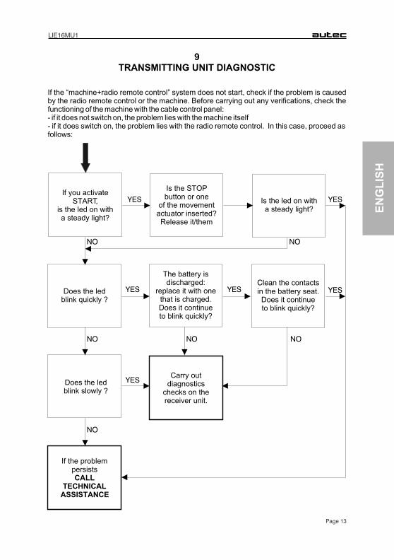
TRANSMITTING UNIT DIAGNOSTIC
If the “machine+radio remote control” system does not start, check if the problem is caused by the radio remote control or the machine. Before carrying out any verifications, check the functioning of the machine with the cable control panel: - if it does not switch on, the problem lies with the machine itself- if it does switch on, the problem lies with the radio remote control. In this case, proceed as follows:
EN
GL
ISH
Is the led on with a steady light?
Is the STOP button or one
of the movement actuator inserted?Release it/them
The battery is discharged:
replace it with one that is charged.Does it continue to blink quickly?
Clean the contacts in the battery seat. Does it continue to blink quickly?
Does the led blink quickly ?
If the problem persists CALL
TECHNICALASSISTANCE
Carry out diagnostics
checks on the receiver unit.
NO
YES
NO
NO
NO NO
NO
If you activate START,
is the led on with a steady light?
Does the led blink slowly ?
YES
YES YESYES
YES