Embed Size (px)
Citation preview

Lice
nsed
Cop
y: J
ohn
May
, Pow
ertr
ain
Ltd.
, Feb
ruar
y 20
, 200
2, U
ncon
trol
led
Cop
y, (
c) B
SI
BRITISH STANDARD BS 970-3:1991Incorporating Amendment Nos. 1 and 2
Specification for
Wrought steel for mechanical and allied engineering purposes —
Part 3: Bright bars for general engineering purposes
Lice
nsed
Cop
y: J
ohn
May
, Pow
ertr
ain
Ltd.
, Feb
ruar
y 20
, 200
2, U
ncon
trol
led
Cop
y, (
c) B
SI

BS 970-3:1991
This British Standard, having been prepared under the direction of the Iron and Steel Standards Policy Committee, was published under the authority of the Standards Board and comes into effect on 20 December 1991
© BSI 11-1998
First published July 1941Second edition October 1942Third edition March 1947Fourth edition January 1955Fifth edition July 1971Sixth edition December 1991
The following BSI references relate to the work on this standard:Committee reference ISM/31Draft for comment 91/46105 DC
ISBN 0 580 1 9999 1
Committees responsible for this British Standard
The preparation of this British Standard was entrusted by the Iron and Steel Standards Policy Committee (ISM/-) to Technical Committee ISM/31, upon which the following bodies were represented:
Associated Offices Technical CommitteeBritish Chain Manufacturers’ AssociationBritish Coal CorporationBritish Forging Industry AssociationBritish Industrial Fasteners FederationBritish Railways BoardBritish Steel IndustryCold Rolled Sections AssociationDepartment of Trade and Industry (National Physical Laboratory)Engineering Industries AssociationFederation of British Engineers’ Tool ManufacturersLloyds Register of ShippingMinistry of DefenceNational Association of Steel StockholdersRoad Vehicle Spring SocietySociety of Motor Manufacturers and Traders LimitedStainless Steel Fabricators’ Association of Great Britain
Amendments issued since publication
Amd. No. Date Comments
7227 September 1992
8974 November 1995
Indicated by a sideline in the margin
Lice
nsed
Cop
y: J
ohn
May
, Pow
ertr
ain
Ltd.
, Feb
ruar
y 20
, 200
2, U
ncon
trol
led
Cop
y, (
c) B
SI

BS 970-3:1991
© BSI 11-1998 i
Contents
PageCommittees responsible Inside front coverForeword iii
1 Scope 12 Definitions and symbols 13 Information and requirements to be agreed and to be documented 24 General 25 Steelmaking process and casting methods 36 Dimensional tolerances 37 Selection and preparation of test samples 48 Test methods and test results 59 Chemical composition 610 Mechanical properties 611 Retests 812 Freedom from defects 813 Marking 9
Appendix A Options 30
Table 1 — Tolerances for cold drawn bars 3Table 2 — Tolerances for turned bars 4Table 3 — Tolerances for precision ground bars 4Table 4 — Straightness tolerances 4Table 5 — Maximum limits on residual elements 6Table 6 — Permitted variations of product analysis from specified range 6Table 7 — Rounds, squares and hexagons in sizes from 10 mm up to and including 100 mm diameter or across flat: maximum permissiblesurface defects 8Table 8 — Flats greater than 105 mm wide in free-cutting,semi-free-cutting and carbon steels: maximum permissiblesurface defects 9Table 9 — Flats greater than 105 mm wide in hot and coldforging steels and low alloy steels: maximum permissibledefect depths 9Table 10 — Flats equal to or less than 105 mm wide infree-cutting, semi-free-cutting and carbon steels: maximumpermissible defect depths 10Table 11 — Flats equal to or less than 105 mm wide in hot andcold forging steels and low alloy steels: maximum permissibledefect depths 10Table 12 — Chemical composition: free-cutting steels 10Table 13 — Chemical composition: carbon and carbon manganesesteels 11Table 14 — Chemical composition: case hardening steels (carbon andcarbon manganese steels) 11Table 15 — Chemical composition: alloy case hardening steels 11Table 16 — Chemical composition: alloy direct hardening steels 12Table 17 — Chemical composition: ferritic and martensitic stainlessand heat resisting steels 12Table 18 — Chemical composition: Austenitic stainless and heatresisting steels 13Table 19 — Mechanical properties for free-cutting steels 14
Lice
nsed
Cop
y: J
ohn
May
, Pow
ertr
ain
Ltd.
, Feb
ruar
y 20
, 200
2, U
ncon
trol
led
Cop
y, (
c) B
SI

BS 970-3:1991
ii © BSI 11-1998
PageTable 20 — Mechanical properties for carbon and carbon manganesesteels 15Table 21 — Mechanical properties for alloy steels 18Table 22 — Mechanical properties for case hardening steels 23Table 23 — Heat treatment and mechanical properties for ferritic andmartensitic stainless and heat resisting steels 24Table 24 — Softening treatment and mechanical properties for austenitic stainless and heat resisting steels in the finally softened condition 26Table 25 — Mechanical properties for austenitic stainless steels in thecold drawn condition 27Table 26 — Mechanical properties for austenitic stainless steels in the softened and finally cold drawn condition 27Table 27 — Normalizing for carbon and carbon manganese steels 27Table 28 — Hardening and tempering parameters for free-cutting,carbon and carbon manganese, and alloy steels 28Table 29 — Reference symbols for tensile strength ranges of hardened and tempered material 29
Publication(s) referred to Inside back cover
Lice
nsed
Cop
y: J
ohn
May
, Pow
ertr
ain
Ltd.
, Feb
ruar
y 20
, 200
2, U
ncon
trol
led
Cop
y, (
c) B
SI

BS 970-3:1991
© BSI 11-1998 iii
Foreword
This Part of BS 970 has been prepared under the direction of the Iron and Steel Standards Policy Committee. It supersedes those clauses concerned with bright finished bars in BS 970-1:1983, which is withdrawn.Technical Committee ISM/31 has decided that requirements for bars supplied in the bright cold finished condition should be withdrawn from BS 970-1:1983 to appear in a separate standard for the sake of clarity and as a preparatory step towards a European Standard for this product range.This Part of BS 970 specifies the requirements for bright cold finished bars in carbon, carbon manganese, alloy, free-cutting and stainless steels supplied in straight lengths.A British Standard does not purport to include all the necessary provisions of a contract. Users of British Standards are responsible for their correct application.
Compliance with a British Standard does not of itself confer immunity from legal obligations.
Summary of pagesThis document comprises a front cover, an inside front cover, pages i to iv,pages 1 to 30, an inside back cover and a back cover.This standard has been updated (see copyright date) and may have had amendments incorporated. This will be indicated in the amendment table on the inside front cover.
Lice
nsed
Cop
y: J
ohn
May
, Pow
ertr
ain
Ltd.
, Feb
ruar
y 20
, 200
2, U
ncon
trol
led
Cop
y, (
c) B
SI

iv blank
Lice
nsed
Cop
y: J
ohn
May
, Pow
ertr
ain
Ltd.
, Feb
ruar
y 20
, 200
2, U
ncon
trol
led
Cop
y, (
c) B
SI
BS 970-3:1991
© BSI 11-1998 1
1 ScopeThis Part of BS 970 specifies requirements for carbon and carbon manganese, alloy, free-cutting and stainless steels normally supplied in the bright cold finished condition. It is only applicable to steels supplied in straight lengths.In addition to the definitive requirements, this Part of BS 970 also requires the items detailed in clause 3 to be documented. For compliance with this Part of BS 970, both the definitive requirements and the documented items have to be satisfied.Special ordering options to be called up as required by the purchaser are included in appendix A.NOTE The titles of the publications referred to in this standard are listed on the inside back cover.
2 Definitions and symbols2.1 Definitions
For the purposes of this Part of BS 970 the following definitions apply.
2.1.1 bright cold drawn bars
bars of various cross-sectional shapes obtained, after descaling, by drawing of hot rolled bars or rod, through a die (cold deformation without removing material)NOTE This operation gives the product special features with respect to shape, dimensional accuracy and surface finish. In addition, the process causes cold working of the product, which can be eliminated by subsequent heat treatment. Products in lengths are delivered straightened regardless of size.
2.1.2 bright turned bars
bars of circular cross section having the special features of drawn product concerning shape, dimensional accuracy and bright surface finish with the additional benefit of metal removal on decarburization and surface defectiveness produced by turning
2.1.3 precision ground bars
drawn or turned bars of circular cross section given an improved surface finish and dimensional accuracy by grinding or grinding and polishing
2.1.4 annealing
heat treatment consisting of heating and soaking at a suitable temperature followed by cooling under conditions such that, after return to ambient temperature, the metal will be in a structural state closer to that of equilibriumNOTE The heat treatments in 2.1.4 to 2.1.7 can be carried out either before or after cold conversion and can result in surface discolouration.
2.1.5 normalizing
heat treatment consisting of austenitizing followed by air cooling to refine the metallurgical structure (See note to 2.1.4.)
2.1.6 stress relieving
heat treatment including heating and soaking at a suitable temperature followed by cooling at an appropriate rate in order to relieve internal stresses without substantially modifying the structure (See note to 2.1.4.)
2.1.7 hardening and tempering
heat treatment including heating to a temperature above the upper critical temperature followed by rapid cooling by means of a suitable quenching medium and subsequent reheating to a temperature below the lower critical temperature (See note to 2.1.4.)
2.1.8 ruling section
the equivalent diameter of that portion of the product at the time of heat treatment that is most important in relation to mechanical properties
2.1.9 limiting ruling section
the largest diameter in which certain specified mechanical properties are achieved after a specified heat treatment
2.1.10 equivalent diameter
the diameter of a hypothetical bar of infinite length of uniform circular cross section which, if subjected to the same cooling conditions as the product, i.e. same initial and final temperature and same cooling medium, would have a cooling rate at its axis equivalent to that at the slowest cooling position in the product or relevant part
2.1.11 test sample
a sufficient quantity of material taken from the sample product for the purpose of producing one or more test pieces
2.1.12 test piece
part of the test sample, with the specified dimensions, machined or unmachined, brought to the required condition for submission to a given test
Lice
nsed
Cop
y: J
ohn
May
, Pow
ertr
ain
Ltd.
, Feb
ruar
y 20
, 200
2, U
ncon
trol
led
Cop
y, (
c) B
SI

BS 970-3:1991
2 © BSI 11-1998
2.2 symbols
the symbols used in this Part of BS 970 are given in 1.3 of BS 970-1:1991
3 Information and requirements to be agreed and to be documented3.1 Information to be supplied by the purchaser
The following information to be supplied by the purchaser shall be fully documented.Both the definitive requirements specified throughout this Part of BS 970 and the following documented items shall be satisfied before a claim of compliance with this Part of BS 970 can be made and verified:
a) details of the form of section, size, length and quantity; b) the tolerances required on sections (see Table 1 to Table 4);c) the grade of steel required (see Table 5 and Table 6 and Table 12 to Table 28);d) the tolerances required on length;e) surface condition of supply (see clause 12 and Table 7 to Table 11);f) heat treatment condition together with any physical properties required (see Table 19 to Table 28);
3.2 Options
If the purchaser wishes to take up any of the optional requirements given in this Part of BS 970 (see appendix A), such requirements shall be specified at the time of the enquiry and/or order. In the absence of such information, the manufacturer shall supply in accordance with the basic specification.
3.3 Items for agreement
The following items to be agreed between the contracting parties, which are specified in the clauses referred to, shall be fully documented. Both the definitive requirements specified throughout this Part of BS 970 and the following documented items shall be satisfied before a claim of compliance with the standard can be made and verified.
a) If controlled magnetic properties are required they shall be agreed at the time of enquiry and/or order (see 4.3.2).b) If bars shall be supplied with special corrosion protection it shall be specified and agreed at the time of enquiry and/or order (see 4.6).
c) If any particular type of deoxidation is required it shall be agreed at the time of enquiry and/or order (see 5.1).d) If closer dimensional tolerances than those given in Table 1 to Table 4 are required they shall be agreed at the time of enquiry and/or order (see 6.4).e) Results based on test bar sizes of 13 mmor 29 mm shall be agreed at the time of enquiry and/or order (see 7.3.1 and 10.4).f) If mechanical properties other than those in a longitudinal direction are required values shall be agreed at the time of enquiry and/or order (see 7.4.2).g) If a particular grain size range is required it shall be supplied and the method of measurement agreed at the time of enquiry and/or order (see 8.5).h) If restrictions on certain elements in the chemical composition ranges are required this shall be agreed at the time of enquiry and/or order (see 9.1).i) If controlled sulfur and phosphorus ranges other than those specified in Table 12 to Table 18 are required they shall be agreed at the time of enquiry and/or order (see 9.1).j) If specific non-destructive testing is required the inspection technique and the inspection limits shall be agreed at the time of enquiry and/or order (see 12.1 and 12.3.1.4).k) If specific cleanness requirements are required the relevant standard criteria shall be agreed at the time of enquiry and/or order (see 12.2).l) If a maximum decarburization limit is required the level shall be agreed at the time of enquiry and/or order and measured in accordance with BS 6617-1 and BS 6617-2 (see 12.4).m) If end stamping or colour coding is required it shall be agreed at the time of enquiry and/or order (see clause 13).
4 General4.1 Steel products
Steel products shall comply with the specific requirements of this Part of BS 970 and with the specific requirements applicable to the grade concerned. Where any of the options given in appendix A are called up at the time of the enquiry and/or order, the steel products shall, comply with the requirements of any such options.
Lice
nsed
Cop
y: J
ohn
May
, Pow
ertr
ain
Ltd.
, Feb
ruar
y 20
, 200
2, U
ncon
trol
led
Cop
y, (
c) B
SI

BS 970-3:1991
© BSI 11-1998 3
4.2 Carbon, carbon manganese, free-cutting and alloy steels
Where mechanical properties are obtained by heat treatment, the treatment given to the test bars and to material required in the finally heat treated condition shall be as given in Table 19 to Table 28. Unless otherwise specified at the time of enquiry and/or order bars supplied in the non-heat treated condition shall not be hardness tested. (See also option A.1.)
4.3 Stainless steels
4.3.1 Ferritic steels
When bright bars are supplied in the hardened and tempered condition, the heat treatment shall be given either before or after any cold sizingNOTE Bright bars of ferritic steel supplied in the softened condition can be treated before or after any cold sizing.
4.3.2 Austenitic steels
When bright bars are supplied in the softened condition the heat treatment shall be given before drawing, turning or grinding.NOTE If controlled magnetic properties are required,see 3.3 a).
4.3.3 Martensitic steels
Bright bars of martensitic steels shall be supplied in the condition given in Table 23.
4.4 Specific requirements of Table 12 toTable 28
The specific requirements given in Table 12 toTable 28 shall apply to the following:
a) close limits of chemical composition (A grades) where no mechanical or hardenability requirements are specified;b) specified mechanical properties (M grades);NOTE Variations from the specified chemical composition range are permissible provided that the stipulated mechanical properties are attained.
c) specified hardenability properties (H grades).NOTE Properties given in the appropriate hot rolled steel bar standard will apply.
4.5 Cast analysis
The manufacturer shall supply a certificate stating the cast analysis of the material. (See alsooption A.2)
4.6 Corrosion protection
The manufacturer shall supply bars with a coating of a corrosion protection medium. (See also 3.3 b).)
5 Steelmaking process and casting methods5.1 Steelmaking
Steelmaking shall be by any process except the air or mixed air and oxygen bottom blown basic conversion process. (See also 3.3 c).)
5.2 Casting method
The steel shall be cast into ingots or continuously cast blooms or billets (see 12.1). NOTE For the purposes of Table 7 steel 230M07 is supplied as a balanced quality. The other steels listed in Table 12 are supplied as killed free-cutting qualities.Steels listed in Table 13 are supplied as killed carbon steels.Steels listed in Table 14 are supplied as killed carbon or killed coarse grain steels depending upon ordered requirements. Steels in Table 15 and Table 16 are classified as low alloy steels.
6 Dimensional tolerances6.1 Sectional tolerances
6.1.1 Bars shall be supplied to the sectional tolerances given in Table 1 to Table 3.
Table 1 — Tolerances for cold drawn bar
6.1.2 Thickness shall be measured within 12 mm of the edge for flats.
Section Size, diameter or width across flats
Permitted variation
Roundmm
≥ 6 ≤ 18> 18 ≤ 30> 30 ≤ 50> 50 ≤ 80> 80 ≤ 100
mm+ 0 to – 0.070+ 0 to – 0.085+ 0 to – 0.100+ 0 to – 0.120+ 0 to – 0.140
Square and hexagon
≥ 6 ≤ 18> 18 ≤ 30> 30 ≤ 50> 50 ≤ 80> 80 ≤ 105
+ 0 to – 0.090+ 0 to – 0.110+ 0 to – 0.130+ 0 to – 0.160+ 0 to – 0.250
Flat (width) < 18> 18 ≤ 30> 30 ≤ 50> 50 ≤ 80> 80 ≤ 100> 100 ≤ 130> 130 ≤ 160> 160 ≤ 320
+ 0 to – 0.110+ 0 to – 0.130+ 0 to – 0.160+ 0 to – 0.190+ 0 to – 0.220+ 0 to – 0.350+ 0 to – 1.00+ 1.00 to – 1.00
Flat (thickness) < 18> 18 ≤ 30> 30 ≤ 50> 50 ≤ 80
+ 0 to – 0.110+ 0 to – 0.130+ 0 to – 0.250+ 0 to – 0.350
Lice
nsed
Cop
y: J
ohn
May
, Pow
ertr
ain
Ltd.
, Feb
ruar
y 20
, 200
2, U
ncon
trol
led
Cop
y, (
c) B
SI

BS 970-3:1991
4 © BSI 11-1998
6.1.3 The diameter of round bars in the as drawn length shall be measured at a distance of at least 150 mm from the end of the bar. Where round bars have been re-cut to an exact length the diameter shall be measured at least 10 mm from the end of the bar.6.1.4 The cross-sectional measurement of hexagons, squares and flat bars shall be measured at least 25 mm from the end of the bar.NOTE The very ends of such bars might not necessarily meet the requirements of Table 1 but these should not be regarded as defective if the remainder is in accordance with Table 1.
Table 2 — Tolerances for turned bars
6.2 Tolerances for precision ground bars
6.2.1 The appropriate dimensional tolerance class required shall be as selected by the purchaser (see Table 3). Surface texture shall be 0.8 µm centre line average maximum (0.8 µm Ra max.) in accordance with BS 1134-1.
Table 3 — Tolerances for precision ground bars
6.2.2 Maximum deviation from “out of round” shall be no more than half the ordered diametric tolerance, as measured using a 60° 3-point gauge.6.2.3 Bars with cold sheared ends shall be measured at a distance from the end not less than the diameter of the bar.
6.3 Straightness tolerance
Drawn and turned bars shall be supplied to the tolerances given in Table 4 and shall be measured as maximum deviation from straightness in any 3 000 mm portion of the bar.
Table 4 — Straightness tolerances
6.4 Special tolerances
The basic specification shall comply with the dimensional tolerances given in Table 1 to Table 4, as appropriate. (See also 3.3 d).)
7 Selection and preparation of test samples7.1 Selection of test samples
One tensile test and where relevant, one Izod impact test sample, comprising three notches, or three Charpy V-notch impact test samples shall be taken from any batch of the same cast. For the purpose of subsequent orders, these tests shall be taken as representing all sizes of material from the same cast where the ruling section of the parts does not exceed the ruling section of the test bar already tested. The samples shall be cut from the heat treated bars or cold finished bars and shall not be further heat treated or mechanically worked after their removal.
7.2 Steel of tensile strength of 1 225 N/mm2 or greater
Where the tensile strength of alloy steel is specified as 1 225 N/mm2 minimum or greater, the test sample shall be machined to test piece size, plus a grinding allowance if required, before heat treatment.
7.3 Steels for case hardening
7.3.1 Size of test sample
The test sample size shall be 19 mm diameter.(See also 3.3 e).)
Size, diameter Permitted variation
mm≥ 6 ≤ 18> 18 ≤ 30> 30 ≤ 50> 50 ≤ 80> 80 ≤ 120> 120 ≤ 180> 180 ≤ 250> 250 ≤ 315> 315 ≤ 400> 400
mm+ 0 to – 0.070+ 0 to – 0.085+ 0 to – 0.100+ 0 to – 0.120+ 0 to – 0.140+ 0 to – 0.160+ 0 to – 0.185+ 0 to – 0.210+ 0 to – 0.230+ 0 to – 0.250
Section Size, diameter
Permitted overall variation
Class A Class B Class C
Roundmm
≥ 6 < 75mm
0.050mm
0.025mm
0.013
Section Steel grade Permitted variation
Rounds < 0.25 % carbon 1 in1 000
≥ 0.25 % carbon, alloys and all heat treated grades
1 in 500
Squares and hexagons
< 0.25 % carbon ≤ 75 mm> 75 mm
1 in 750 1 in 500
≥ 0.25 % carbon, alloys and all heat treated grades
1 in 375
Flats < 0.25 % carbon 1 in 500
≥ 0.25 % carbon, alloys and all heat treated grades
1 in 375
Lice
nsed
Cop
y: J
ohn
May
, Pow
ertr
ain
Ltd.
, Feb
ruar
y 20
, 200
2, U
ncon
trol
led
Cop
y, (
c) B
SI

BS 970-3:1991
© BSI 11-1998 5
7.3.2 Selection of samples
Subject to 7.3.1 one test sample shall be selected to represent each cast. If the size of the test sample is greater than the specified test piece size, test bars shall be prepared by forging and/or machining to that size; but for sizes smaller than 13 mm diameter for carbon and carbon manganese steels and for sizes smaller than 19 mm diameter for alloy steels, the test pieces shall be heat treated in the full section of the sample.NOTE The properties specified in Table 19 to Table 26 apply only to the preferred test bar sizes and to ruling sections equivalent to these. When components of different ruling sections are carburized and heat treated, different core properties will be obtained. Similarly, it may be necessary to agree mechanical properties when the test sample size is less than the specified test bar size. Attention is also drawn to the influence of several factors such as steel composition, ruling section and heat treatment, on the hardness of the case. For example, even if a low core strength suffices it will be necessary to use an alloy steel for acceptable case hardenability of the largest section sizes.
7.3.3 Heat treatment of test piece
7.3.3.1 Carbon and carbon manganese steels
The test pieces shall be blank carburized for at least 1 h at the hardening temperature between 900 °C and 930 °C and quenched in oil.
7.3.3.2 Alloy steels
The test pieces shall be blank carburized for at least 1 h at a temperature between 800 °C and 930 °C. After cooling to room temperature they shall be reheated to the single quenching temperature, as given in Table 22, and quenched in oil.
7.4 Location of test pieces for mechanical testing
7.4.1 General
Where longitudinal tests are required, the test piece shall be prepared in accordance with the following:
a) For ruling sections up to and including 25 mm, the test piece shall be machined coaxially from the test bars.b) For ruling sections over 25 mm, the longitudinal axis of the test piece shall be 12.5 mm from the surface of the test bars.c) Austenitic stainless steels (see Table 18) supplied as cold drawn bars shall be tested in full section for ruling sections up to and including 19 mm. For ruling sections over 19 mm, the test piece shall be machined coaxially from the test sample.
7.4.2 Transverse and other tests
Where transverse and other tests are required the test piece shall be prepared as specified in the enquiry and/or order. (See also 3.3 f).)
7.5 Frequency of other tests
7.5.1 Number of hardness tests
The manufacturer shall carry out one test per production batch in accordance with the relevant clauses of this Part of BS 970 in order to ensure that the material complies with the specified hardness.
7.5.2 Number of hardenability tests
One test sample selected to represent each cast shall be reduced by forging or rolling to a size not greater than 38 mm diameter which shall represent the full cross section of the material. This test bar shall also be of sufficient size to ensure the complete removal of decarburization in machining to the standard test piece of 25 mm diameter.
8 Test methods and test results8.1 Tensile test
8.1.1 The tensile test shall be carried out in accordance with BS EN 10002-1.8.1.2 The specified mechanical properties shall refer to tests taken in the longitudinal direction.8.1.3 In cases of dispute tensile test pieces shall be machined from bars to the dimensions of the 11.28 mm diameter (100 mm2 cross-sectional area) test piece or, if the test sample is too small, to the dimensions of the largest recommended round test piece that can be obtained having a gauge length equal to 5.65√SO. 8.1.4 For material not greater than 15 mm diameter or width across flats, unmachined test pieces having a gauge length equal to 5.65√SO shall be used.
8.2 Impact test
The impact properties shall be determined in accordance with BS 131-1. (See also option A.3)
8.3 Hardness test
The Brinell hardness test shall be carried out in accordance with BS 240.
8.4 Hardenability test
Hardenability tests shall be carried out in accordance with the appropriate method of BS 4437.
8.5 Grain size test
Grain size tests shall be carried out in accordance with the appropriate method given in BS 4490. (See also 3.3 g).)
8.6 Intercrystalline corrosion test
If an intercrystalline corrosion test is required it shall be as specified at the time of enquiry and/or order. (See also option A.4)
Lice
nsed
Cop
y: J
ohn
May
, Pow
ertr
ain
Ltd.
, Feb
ruar
y 20
, 200
2, U
ncon
trol
led
Cop
y, (
c) B
SI

BS 970-3:1991
6 © BSI 11-1998
9 Chemical composition9.1 Composition ranges
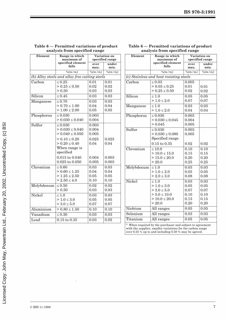
The chemical composition of the steel, based on cast analysis when tested in accordance with BS 6200 shall comply with the appropriate material specifications given in Table 12 to Table 18. (See also 3.3 h), 3.3 i) and option A.5)NOTE In Table 12 to Table 28 figures in parentheses indicate notes which appear at the end of these tables.
9.2 Residual elements
The maximum limits on residual elements shall be as given in Table 5.
Table 5 — Maximum limits on residual elements
9.3 Lead bearing steels
The basic specification shall not include lead. (See also option A.5.)
9.4 Product analysis and permitted deviationsNOTE Product analysis may differ from the cast analysis due to heterogeneity arising during casting and solidification. Table 6 shows the deviations from the range specified for cast analysis permitted on product analysis.
The deviation may occur either above or below the individual element ranges but shall not apply both above and below the specified range for any one element in any one cast of steel. Test specimens for product analysis shall be taken in accordance with BS 6200-3 or BS Handbook 19.
10 Mechanical propertiesNOTE 1 For through hardening steels, the mechanical properties attainable from any steel composition and heat treatment are dependent on the ruling section.NOTE 2 The requirements in this standard show the limiting ruling section to which the stated mechanical properties apply and the purchaser should select a steel which is specified to give the desired properties in the appropriate ruling section at the time of heat treatment.NOTE 3 Generally, specified properties are readily achievable even when bulk heat treatment is involved except where noted in Table 19 to Table 28.NOTE 4 In Table 19 to Table 28 figures in parentheses indicate notes which appear at the end of these tables.
10.1 Tensile properties shall be as given in Table 19 to Table 28 when tested in accordance withBS EN 10002-1. 10.2 Impact properties shall be as given in Table 19 to Table 28 when tested in accordance withBS 131-1.10.3 Hardness properties shall be as given in Table 19 to Table 28 when tested in accordance withBS 240.
Table 6 — Permitted variations of product analysis from specified range
Element Carbon and carbon
manganese grades
Non-austenitic stainless grades
Austenitic stainless grades
%(m/m) %(m/m) %(m/m)
NickelChromiumMolybdenumNiobiumTitaniumCopper
0.400.300.15———
——0.30——0.30
——1.000.200.100.70
Element Range in which maximum of
specified element falls
Variation on specified range
over max.
under min.
%(m/m) %(m/m) %(m/m)
(a) Carbon, carbon manganese and free cutting steels
Carbona ≤ 0.25> 0.25 ≤ 0.50> 0.50 ≤ 1.05
0.020.030.04
0.020.030.04
Silicon ≤ 0.40 0.03 0.03Manganese ≤ 1.00
> 1.00 ≤ 1.50> 1.50
0.040.080.10
0.040.080.10
Phosphorus ≤ 0.025 > 0.025 ≤ 0.040> 0.040 ≤ 0.060
0.0050.0060.008
Sulfur ≤ 0.025> 0.025 ≤ 0.040> 0.040 ≤ 0.060> 0.060 ≤ 0.10
0.0050.0060.0080.010
> 0.10 ≤ 0.20> 0.20 ≤ 0.40When range is specified
0.0250.040
0.0250.040
0.015 to 0.0400.025 to 0.0500.050 to 0.10
0.0060.0080.010
0.0030.0050.008
Lead 0.15 to 0.35 0.03 0.02
Lice
nsed
Cop
y: J
ohn
May
, Pow
ertr
ain
Ltd.
, Feb
ruar
y 20
, 200
2, U
ncon
trol
led
Cop
y, (
c) B
SI
BS 970-3:1991
© BSI 11-1998 7
Table 6 — Permitted variations of product analysis from specified range
Table 6 — Permitted variations of product analysis from specified range
Element Range in which maximum of
specified element falls
Variation on specified range
over max.
under min.
%(m/m) %(m/m) %(m/m)
(b) Alloy steels and alloy free cutting steelsCarbon ≤ 0.25
> 0.25 ≤ 0.50> 0.50
0.010.020.03
0.010.020.03
Silicon ≤ 0.45 0.03 0.03Manganese ≤ 0.70
> 0.70 ≤ 1.00> 1.00 ≤ 2.00
0.030.040.05
0.030.040.05
Phosphorus ≤ 0.030> 0.030 ≤ 0.040
0.0030.004
Sulfur ≤ 0.030> 0.030 ≤ 0.040> 0.040 ≤ 0.050
0.0030.0040.005
> 0.10 ≤ 0.20> 0.20 ≤ 0.40When range is specified
0.0250.04
0.0250.04
0.015 to 0.0400.025 to 0.050
0.0040.005
0.0030.003
Chromium ≤ 0.60> 0.60 ≤ 1.25> 1.25 ≤ 2.50> 2.50 ≤ 4.0
0.030.040.050.10
0.030.040.050.10
Molybdenum ≤ 0.50> 0.50
0.020.03
0.020.03
Nickel ≤ 1.0> 1.0 ≤ 3.0> 3.0 ≤ 5.0
0.030.050.07
0.030.050.07
Aluminium > 0.80 ≤ 1.50 0.10 0.10Vanadium ≤ 0.30 0.03 0.03Lead 0.15 to 0.35 0.03 0.02
Element Range in which maximum of
specified element falls
Variation on specified range
over max.
under min.
%(m/m) %(m/m) %(m/m)
(c) Stainless and heat resisting steelsCarbon ≤ 0.03
> 0.03 ≤ 0.25> 0.25 ≤ 0.50
0.0050.010.02
0.010.02
Silicon ≤ 1.0> 1.0 ≤ 2.0
0.050.07
0.050.07
Manganese ≤ 1.0> 1.0 ≤ 2.0
0.030.04
0.030.04
Phosphorus ≤ 0.030> 0.030 ≤ 0.045> 0.045
0.0030.0040.005
Sulfur ≤ 0.030> 0.030 ≤ 0.080Specified range
0.0030.005
0.15 to 0.35 0.02 0.02Chromium ≤ 10.0
> 10.0 ≤ 15.0> 15.0 ≤ 20.0> 20.0
0.100.150.200.25
0.100.150.200.25
Molybdenum ≤ 1.0> 1.0 ≤ 2.0> 2.0 ≤ 3.0
0.030.050.08
0.030.050.08
Nickel ≤ 1.0> 1.0 ≤ 3.0> 3.0 ≤ 5.0> 5.0 ≤ 10.0> 10.0 ≤ 20.0> 20.0
0.030.050.070.100.150.20
0.030.050.070.100.150.20
Niobium All ranges 0.05 0.05Selenium All ranges 0.03 0.03Titanium All ranges 0.05 0.05a When required by the purchaser and subject to agreement with the supplier, smaller variations for the carbon range over 0.25 % up to and including 0.50 % may be agreed.
Lice
nsed
Cop
y: J
ohn
May
, Pow
ertr
ain
Ltd.
, Feb
ruar
y 20
, 200
2, U
ncon
trol
led
Cop
y, (
c) B
SI

BS 970-3:1991
8 © BSI 11-1998
10.4 The 19 mm test piece size shall be used.(See also 3.3 e).)NOTE 1 For carbon and carbon manganese case hardening steels, it is customary to test and release steel to specified mechanical property levels using a standard size of test piece. However, because of the effect of section size, the properties are quoted for different test piece sizes in the oil-quenched condition, i.e. 13 mm, 19 mm and 29 mm, but the 19 mm test piece is to be used unless otherwise agreed.NOTE 2 The properties specified for both carbon and alloy steels apply only to the test piece size used and the heat treatment specified. If other heat treatments and/or sizes of test piece are used, then different results may be obtained. The conditions for these heat treatments and tests should be agreed between the purchaser and the supplier.NOTE 3 The properties obtained are representative of those bars heat treated in the same ruling section as that of the test piece and may not represent larger ruling sections.
11 Retests 11.1 General
Retests shall be carried out as specified in 11.2 to 11.4. If any test sample or test piece fails to comply with the specified requirements as a result of incorrect application of the test procedure or faulty equipment, the test results shall be discarded and a further test sample(s) shall be retested.
11.2 Tensile tests
11.2.1 Should any of the original test pieces fail, twice the original number of test samples shall be selected for retesting, one of which shall be taken from the bar from which the original test sample was taken, unless that item has been withdrawn by the manufacturer. 11.2.2 The mechanical properties obtained from the test pieces prepared from the further test samples shall comply with the specified requirements. Should any of the retests fail, the material represented shall be deemed not to comply with this standard.11.2.3 In the case of material supplied in the heat treated condition, the manufacturer shall have the right to re-heat treat the material and resubmit it for retesting.11.2.4 In the case of dispute with the reported yield stress the 0.5 % proof stress (total elongation) shall be used.
11.3 Impact test
11.3.1 If the average of three impact values is lower than the specified value, or if any one value is lower than 70 % of this specified value, three additional test pieces shall be taken from the same sample and tested. The average value of the six tests shall be not less than the specified value. Not more than two of the individual values shall be lower than the specified value and not more than one shall be lower than 70 % of this value.
11.3.2 In the case of material supplied in the heat treated condition, the manufacturer shall have the right to re-heat treat the material and resubmit it for retesting.
11.4 Hardness test
11.4.1 Should the hardness value determined on any bar fail to comply with the specified requirements, then three additional test samples of items shall be selected for retesting, one of which shall be from the original bar unless that item has been withdrawn by the manufacturer.
12 Freedom from defects12.1 Internal soundness
The procedures for casting, hot-working, re-heating and cooling shall ensure that the product is free from piping, central unsoundness and harmful segregation.NOTE Where assurance is required see also 3.3 j).
12.2 Cleanness
If specific levels of cleanness are required, they shall be in accordance with the standards specified in the enquiry and/or order, see 3.3 k).NOTE Sulfide inclusions and segregation lines which are intrinsic to free-cutting steels are not to be regarded as a defect in the material.
12.3 Surface condition
12.3.1 Cold drawn bar and cold drawn and ground bar
12.3.1.1 Surface defects shall not exceed the maximum values given in Table 7 to Table 11, in bars supplied in the cold drawn and cold drawn and ground condition.
Table 7 — Rounds, squares and hexagons in sizes from 10 mm up to and including 100 mm diameter or across flat: maximum permissible
surface defects
12.3.1.2 The minimum rejectable defect depth for balanced free-cutting, killed free-cutting, killed carbon and killed coarse grain steels shall be 0.25 mm irrespective of section, and for hot or cold forging and low alloy and stainless steels it shall be 0.20 mm.
Steel type Maximum permissible defect depth as percentage
of section
%
Balanced free-cutting Killed free-cuttingKilled carbonKilled coarse grainHot or cold forgingLow alloy and stainless
2.001.251.002.000.750.75
Lice
nsed
Cop
y: J
ohn
May
, Pow
ertr
ain
Ltd.
, Feb
ruar
y 20
, 200
2, U
ncon
trol
led
Cop
y, (
c) B
SI

BS 970-3:1991
© BSI 11-1998 9
Table 8 — Flats greater than 105 mm wide in free-cutting, semi-free-cutting and carbon
steels: maximum permissible surface defects
12.3.1.3 The maximum permissible defect depth on the surfaces of the narrower or edge faces of flats in qualities and sizes covered by Table 8 shall be 1 mm.Table 9 — Flats greater than 105 mm wide in
hot and cold forging steels and low alloy steels: maximum permissible defect depths
12.3.1.4 The maximum permissible defect depth on the surface of the narrower or edge face of flats in qualities and sizes covered by Table 9 shall be 0.7 min.NOTE Where specific assurance of maximum defect levels is required materials can be supplied crack detected.(See also3.3 j).)
12.3.2 Turned bar and turned and ground bar
The stock removal during the manufacture of bars to be supplied in the turned or turned and ground condition, shall be sufficient to ensure freedom from surface defects of steel making or hot rolling origin.
12.4 Decarburization
Turned or turned and ground bars shall be free from decarburization.NOTE For bars produced by drawing see also 3.3 l).
13 MarkingUnless otherwise specified at the time of enquiry and/or order bars shall be supplied labelled but unmarked.(See 3.3 m).)
Thickness Maximum permissible defect depth on the wider or flat faces
Widths > 105 mmto ≤≤ 160 mm
Widths > 160 mm
mm> 3 ≤ 10> 10 ≤ 18> 18 ≤ 30> 30 ≤ 50> 50 ≤ 80> 80 ≤ 105> 105
mm0.200.250.300.500.700.801.00
mm0.200.250.450.801.001.001.00
Thickness Maximum permissible defect depth on the wider
or flat faces
mm> 3 ≤ 10> 10 ≤ 18> 18 ≤ 30> 30 ≤ 50> 50 ≤ 80> 80
mm0.100.150.200.300.500.70
NOTE The defect is to be measured perpendicular to the bar surface.
Lice
nsed
Cop
y: J
ohn
May
, Pow
ertr
ain
Ltd.
, Feb
ruar
y 20
, 200
2, U
ncon
trol
led
Cop
y, (
c) B
SI

BS 970-3:1991
10 © BSI 11-1998
Table 10 — Flats equal to or less than 105 mm wide in free-cutting, semi-free-cutting and carbon steels: maximum permissible defect depths
Table 11 — Flats equal to or less than 105 mm wide in hot and cold forging steels, and alloy steels: maximum permissible defect depths
Table 12 — Chemical composition: free-cutting steels
Thickness Maximum permissible defect depths
Wider or flat face Narrower or edge face
Widths
≤ 30 mm > 30 mm ≤ 50 mm > 50 mm ≤ 80 mm > 80 mm ≤ 105 mm
mm mm mm mm mm mm
> 3 ≤ 10> 10 ≤ 18> 18 ≤ 30> 30 ≤ 50> 50 ≤ 80
0.20.30.40.60.7
0.40 0.65 0.80 1.00
NOTE The defect is to be measured perpendicular to the bar surface.
Thickness Maximum permissible defect depths
Wider or flat face Narrower or edge face
Widths
≤ 30 mm > 30 mm ≤ 50 mm > 50 mm ≤ 80 mm > 80 mm ≤ 105 mm
mm mm mm mm mm mm
> 3 ≤ 10> 10 ≤ 18> 18 ≤ 30> 30 ≤ 50> 50 ≤ 80
0.150.150.200.300.50
0.20 0.30 0.50 0.70
NOTE The defect is to be measured perpendicular to the bar surface.
Steel C Si Mn P S
%(m/m) %(m/m) %(m/m) %(m/m) %(m/m)
230M07216M36212A42226M44
0.15 max.0.32 to 0.400.40 to 0.450.40 to 0.48
0.05 max.0.25 max.0.25 max.0.25 max.
0.90 to 1.301.30 to 1.701.00 to 1.301.30 to 1.70
0.090 max.0.06 max.0.06 max.0.06 max.
0.25 to 0.350.12 to 0.200.12 to 0.200.22 to 0.30
Lice
nsed
Cop
y: J
ohn
May
, Pow
ertr
ain
Ltd.
, Feb
ruar
y 20
, 200
2, U
ncon
trol
led
Cop
y, (
c) B
SI

BS 970-3:1991
© BSI 11-1998 11
Table 13 — Chemical composition: carbon and carbon manganese steels
Table 14 — Chemical composition: case hardening steels (carbon and carbon manganese steels)
Table 15 — Chemical composition: alloy case hardening Steelsa
Steel C Si Mn P S
%(m/m) %(m/m) %(m/m) %(m/m) %(m/m)
080A15080M15070M20080A30080M30080M40080A42080A47080M50070M55150M19150M36
0.13 to 0.180.12 to 0.180.16 to 0.240.26 to 0.340.26 to 0.340.36 to 0.440.40 to 0.450.45 to 0.500.45 to 0.550.50 to 0.600.15 to 0.230.32 to 0.40
0.10 to 0.400.10 to 0.400.10 to 0.400.10 to 0.400.10 to 0.400.10 to 0.400.10 to 0.400.10 to 0.400.10 to 0.400.10 to 0.400.10 to 0.400.10 to 0.40
0.70 to 0.900.60 to 1.000.50 to 0.900.70 to 0.900.60 to 1.000.60 to 1.000.70 to 0.900.70 to 0.900.60 to 1.000.50 to 0.901.30 to 1.701.30 to 1.70
0.05 max.0.05 max.0.05 max.0.05 max.0.05 max.0.05 max.0.05 max.0.05 max.0.05 max.0.05 max.0.05 max.0.05 max.
0.05 max.0.05 max.0.05 max.0.05 max.0.05 max.0.05 max.0.05 max.0.05 max.0.05 max.0.05 max.0.05 max.0.05 max.
NOTE See also 3.3 g) and option A.1, A.2 and A.4.
Steel C Si Mn P S
%(m/m) %(m/m) %(m/m) %(m/m) %(m/m)
045A10045M10080M15210M15
0.08 to 0.130.07 to 0.130.12 to 0.180.12 to 0.18
0.10 to 0.400.10 to 0.400.10 to 0.400.10 to 0.40
0.30 to 0.600.30 to 0.600.60 to 1.000.90 to 1.30
0.05 max.0.05 max.0.05 max.0.05 max.
0.05 max.0.05 max.0.05 max.0.10 to 0.18
Steel C Si Mn Cr Mo Ni
%(m/m) %(m/m) %(m/m) %(m/m) %(m/m) %(m/m)
635M15637M17655M13665M17805M17805M20815M17820M17822M17835M15
0.12 to 0.180.14 to 0.200.10 to 0.160.14 to 0.200.14 to 0.200.17 to 0.230.14 to 0.200.14 to 0.200.14 to 0.200.12 to 0.18
0.10 to 0.400.10 to 0.400.10 to 0.400.10 to 0.400.10 to 0.400.10 to 0.400.10 to 0.400.10 to 0.400.10 to 0.400.10 to 0.40
0.60 to 0.900.60 to 0.900.35 to 0.600.35 to 0.750.60 to 0.950.60 to 0.950.60 to 0.900.60 to 0.900.40 to 0.700.25 to 0.50
0.4 to 0.800.60 to 1.000.70 to 1.00—0.35 to 0.650.35 to 0.650.80 to 1.200.80 to 1.201.30 to 1.701.00 to 1.40
———0.20 to 0.300.15 to 0.250.15 to 0.250.10 to 0.200.10 to 0.200.15 to 0.250.15 to 0.30
0.70 to 1.100.85 to 1.253.00 to 3.751.50 to 2.000.35 to 0.750.35 to 0.751.20 to 1.701.50 to 2.001.75 to 2.253.90 to 4.30
NOTE See also 3.3 c), 3.3 i) and options A.2 and A.5.
a Sulfur 0.05 % max., phosphorous 0.04 % max. for all qualities.
Lice
nsed
Cop
y: J
ohn
May
, Pow
ertr
ain
Ltd.
, Feb
ruar
y 20
, 200
2, U
ncon
trol
led
Cop
y, (
c) B
SI
BS
970-3:1991
12©
BS
I 11-1998
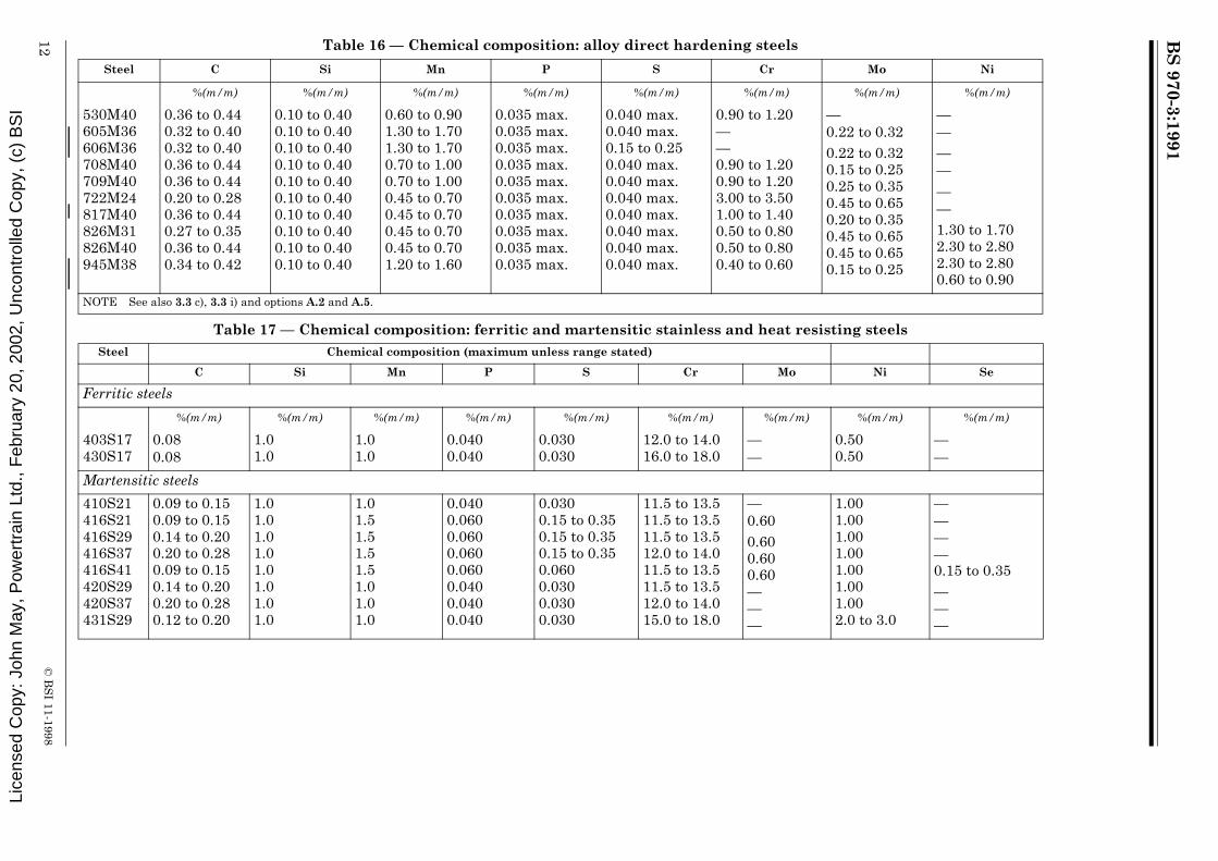
Table 16 — Chemical composition: alloy direct hardening steels
Table 17 — Chemical composition: ferritic and martensitic stainless and heat resisting steels
Steel C Si Mn P S Cr Mo Ni
%(m/m) %(m/m) %(m/m) %(m/m) %(m/m) %(m/m) %(m/m) %(m/m)
530M40605M36606M36708M40709M40722M24817M40826M31826M40945M38
0.36 to 0.440.32 to 0.400.32 to 0.400.36 to 0.440.36 to 0.440.20 to 0.280.36 to 0.440.27 to 0.350.36 to 0.440.34 to 0.42
0.10 to 0.400.10 to 0.400.10 to 0.400.10 to 0.400.10 to 0.400.10 to 0.400.10 to 0.400.10 to 0.400.10 to 0.400.10 to 0.40
0.60 to 0.901.30 to 1.701.30 to 1.700.70 to 1.000.70 to 1.000.45 to 0.700.45 to 0.700.45 to 0.700.45 to 0.701.20 to 1.60
0.035 max.0.035 max.0.035 max.0.035 max.0.035 max.0.035 max.0.035 max.0.035 max.0.035 max.0.035 max.
0.040 max.0.040 max.0.15 to 0.250.040 max.0.040 max.0.040 max.0.040 max.0.040 max.0.040 max.0.040 max.
0.90 to 1.20——0.90 to 1.200.90 to 1.203.00 to 3.501.00 to 1.400.50 to 0.800.50 to 0.800.40 to 0.60
—0.22 to 0.320.22 to 0.320.15 to 0.250.25 to 0.350.45 to 0.650.20 to 0.350.45 to 0.650.45 to 0.650.15 to 0.25
——————1.30 to 1.702.30 to 2.802.30 to 2.800.60 to 0.90
NOTE See also 3.3 c), 3.3 i) and options A.2 and A.5.
Steel Chemical composition (maximum unless range stated)
C Si Mn P S Cr Mo Ni Se
Ferritic steels
%(m/m) %(m/m) %(m/m) %(m/m) %(m/m) %(m/m) %(m/m) %(m/m) %(m/m)
403S17430S17
0.080.08
1.01.0
1.01.0
0.0400.040
0.0300.030
12.0 to 14.016.0 to 18.0
——
0.500.50
——
Martensitic steels
410S21416S21416S29416S37416S41420S29420S37431S29
0.09 to 0.150.09 to 0.150.14 to 0.200.20 to 0.280.09 to 0.150.14 to 0.200.20 to 0.280.12 to 0.20
1.01.01.01.01.01.01.01.0
1.01.51.51.51.51.01.01.0
0.0400.0600.0600.0600.0600.0400.0400.040
0.0300.15 to 0.350.15 to 0.350.15 to 0.350.0600.0300.0300.030
11.5 to 13.511.5 to 13.511.5 to 13.512.0 to 14.011.5 to 13.511.5 to 13.512.0 to 14.015.0 to 18.0
—0.600.600.600.60———
1.001.001.001.001.001.001.002.0 to 3.0
————0.15 to 0.35———
Lice
nsed
Cop
y: J
ohn
May
, Pow
ertr
ain
Ltd.
, Feb
ruar
y 20
, 200
2, U
ncon
trol
led
Cop
y, (
c) B
SI

BS
970-3:1991
© B
SI 11-1998
13
Table 18 — Chemical composition: austenitic stainless and heat resisting steelsSteel Chemical composition (maximum unless range stated)
C Si Mn P S Cr Mo Ni Others
Austenitic steels
%(m/m) %(m/m) %(m/m) %(m/m) %(m/m) %(m/m) %(m/m) %(m/m) %(m/m)
302S31304S11304S15304S31321S31347S31316S11316S13316S31316S33320S31310S31303S31303S42325S31
0.120.0300.060.070.080.080.0300.0300.070.070.080.150.120.120.12
1.01.01.01.01.01.01.01.01.01.01.01.51.01.01.0
2.02.02.02.02.02.02.02.02.02.02.02.02.02.02.0
0.0450.0450.0450.0450.0450.0450.0450.0450.0450.0450.0450.0450.0600.0600.045
0.0300.0300.0300.0300.0300.0300.0300.0300.0300.0300.0300.0300.15 to 0.350.0600.15 to 0.35
17.0 to 19.017.0 to 19.017.5 to 19.017.0 to 19.017.0 to 19.017.0 to 19.016.5 to 18.516.5 to 18.516.5 to 18.516.5 to 18.516.5 to 18.524.0 to 26.017.0 to 19.017.0 to 19.017.0 to 19.0
——————2.00 to 2.502.50 to 3.002.00 to 2.502.50 to 3.002.00 to 2.50—1.00 (9)1.00 (9)—
8.0 to 10.09.0 to 12.08.0 to 11.08.0 to 11.09.0 to 12.09.0 to 12.0
11.0 to 14.011.5 to 14.510.5 to 13.511.0 to 14.011.0 to 14.019.0 to 22.0
8.0 to 10.08.0 to 10.08.0 to 11.0
————Ti 5C max. 0.80Nb 10C max. 1.00————Ti 5C max. 0.80——Se 0.15 to 0.35Ti 5C max. 0.90
Lice
nsed
Cop
y: J
ohn
May
, Pow
ertr
ain
Ltd.
, Feb
ruar
y 20
, 200
2, U
ncon
trol
led
Cop
y, (
c) B
SI

BS
970-3:1991
14©
BS
I 11-1998
Table 19 — Mechanical properties for free-cutting steels (18)
Steel Condition (2) Size (1) (diameter across flats or
thickness)
Rm Re min. A min. on 5.65 √So
Impacta Rp0.2 (3) min.
HB (13)
Izod min.
KCV min.
mm N/mm2 N/mm2 % J J N/mm2
230M07 Hot rolled + turned or ground
≥ 6 < 100 360 min. 215 22 — — — 103 min.
Hot rolled + cold drawn or hot rolled + cold drawn + ground
≥ 6 ≤ 13> 13 ≤ 16> 16 ≤ 40> 40 ≤ 63> 63 ≤ 76
480 min.460 min.430 min.390 min.370 min.
400380340280240
6789
10
—————
—————
360345300240225
—————
216M36 Hot rolled + cold drawn or hot rolled + cold drawn + ground
≥ 6 < 13> 13 ≤ 16> 16 ≤ 40> 40 ≤ 63> 63 ≤ 76
680 min.650 min.620 min.600 min.570 min.
530510480460420
67789
—————
—————
510487434372353
—————
Hardened and tempered + turned or ground
P ≥ 6 < 100Q > 6 ≤ 63R > 6 ≤ 29
550 to 700625 to 775700 to 850
340400480
201816
343434
282828
310370450
152 to 207179 to 229201 to 255
Hardened and tempered +cold drawn or hardened andtempered + cold drawn +ground
P ≥ 29 < 100Q > 13 ≤ 63R > 6 ≤ 29
550 to 700625 to 775700 to 850
380440520
151312
343434
———
340400470
152 to 207179 to 229201 to 255
226M44 Hardened and tempered +turned or ground
(1)
R ≥ 6 < 100S > 6 ≤ 29T > 6 ≤ 13
700 to 850775 to 925850 to 1 000
450525600
161412
272020
221616
415495585
201 to 255223 to 277248 to 302
Hardened and tempered +cold drawn or hardened andtempered + cold drawn + ground
(4)
R ≥ 6 to < 100S > 6 to ≤ 29T > 6 to ≤ 13
700 to 850775 to 925850 to 1 000
525575630
1210
9
272020
———
435520600
201 to 255223 to 277248 to 302
a See also option A.3.
Lice
nsed
Cop
y: J
ohn
May
, Pow
ertr
ain
Ltd.
, Feb
ruar
y 20
, 200
2, U
ncon
trol
led
Cop
y, (
c) B
SI

BS
970-3:1991
© B
SI 11-1998
15
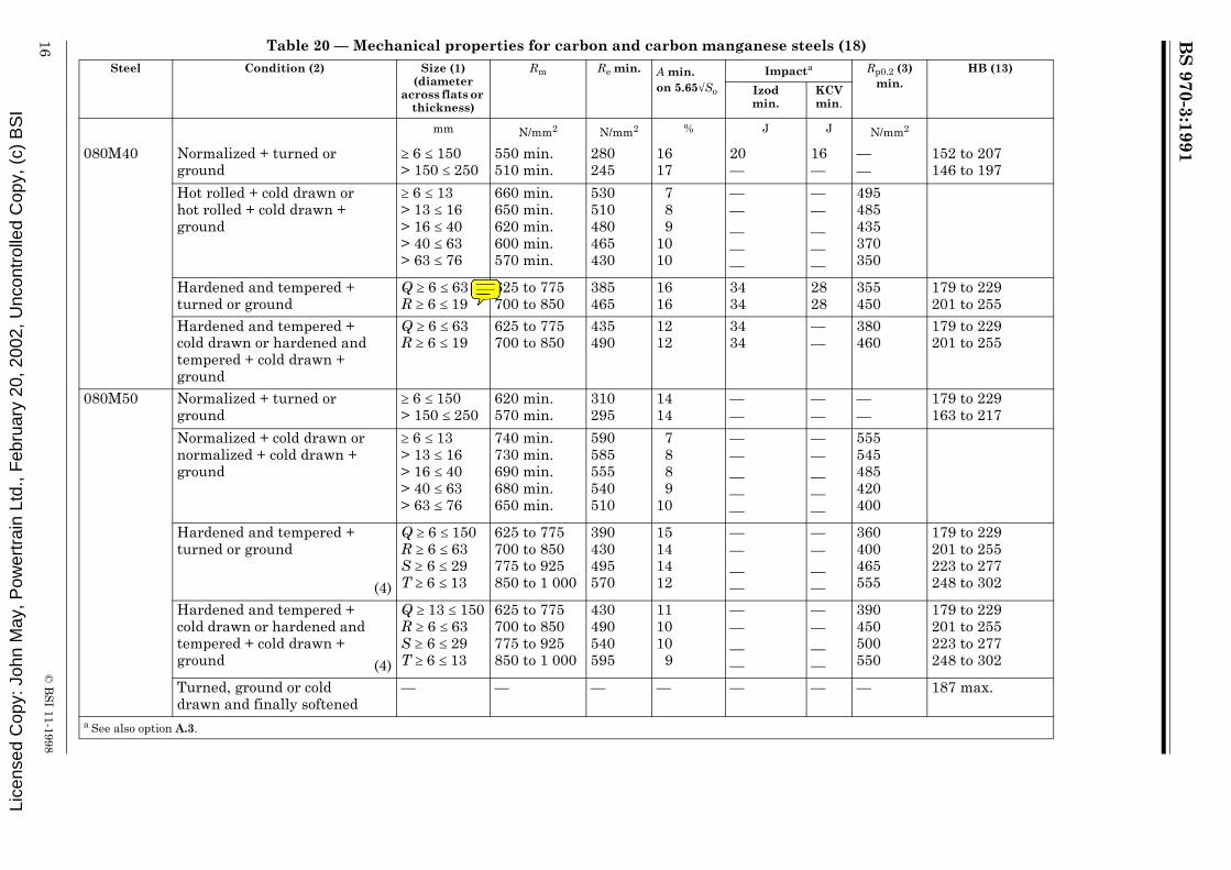
Table 20 — Mechanical properties for carbon and carbon manganese steels (18)Steel Condition (2) Size (1)
(diameter across flats or
thickness)
Rm Re min. A min.on 5.65√So
Impacta Rp0.2 (3) min.
HB (13)
Izodmin.
KCV min.
mm N/mm2 N/mm2 % J J N/mm2
080M15 Normalized + turned orground
≥ 6 ≤ 63> 63 ≤ 150
350 min.330 min.
175165
2222
——
——
——
109 to 163101 to 152
Hot rolled + cold drawn orhot rolled + cold drawn +ground
≥ 6 ≤ 13> 13 ≤ 29> 29 ≤ 100
450 min.430 min.400 min.
330320300
101213
070M20 Normalized + turned orground
≥ 6 ≤ 150> 150 ≤ 250
430 min.400 min.
215200
2121
——
——
——
126 to 179116 to 170
Hot rolled + cold drawn orhot rolled + cold drawn +ground
≥ 6 ≤ 13> 13 ≤ 16> 16 ≤ 40> 40 ≤ 63> 63 ≤ 76
560 min.530 min.490 min.480 min.450 min.
440420370355325
1012121314
—————
—————
420390340290280
—————
080M30 Normalized + turned orground
≥ 6 ≤ 150> 150 ≤ 250
490 min.460 min.
245230
2019
——
——
——
143 to 192134 to 183
Hot rolled + cold drawn orhot rolled + cold drawn +ground
≥ 6 ≤ 13> 13 ≤ 16> 16 ≤ 40> 40 ≤ 63> 63 ≤ 76
620 min.600 min.570 min.560 min.530 min.
480470430415385
910111212
—————
—————
460450400345320
Hardened and tempered +turned or ground
P ≥ 6 ≤ 63Q ≥ 6 ≤ 19
550 to 700625 to 775
340415
1816
3434
2828
310400
152 to 207179 to 229
Hardened and tempered +cold drawn or hardened andtempered + cold drawn +ground
P ≥ 6 ≤ 63Q ≥ 6 ≤ 19
550 to 700625 to 775
385460
1312
3434
——
340430
152 to 207179 to 229
a See also option A.3.
Lice
nsed
Cop
y: J
ohn
May
, Pow
ertr
ain
Ltd.
, Feb
ruar
y 20
, 200
2, U
ncon
trol
led
Cop
y, (
c) B
SI
BS
970-3:1991
16©
BS
I 11-1998
Table 20 — Mechanical properties for carbon and carbon manganese steels (18)
Steel Condition (2) Size (1) (diameter
across flats or thickness)
Rm Re min. A min. on 5.65√So
Impacta Rp0.2 (3) min.
HB (13)
Izod min.
KCV min.
mm N/mm2 N/mm2 % J J N/mm2
080M40 Normalized + turned orground
≥ 6 ≤ 150> 150 ≤ 250
550 min.510 min.
280245
1617
20—
16—
——
152 to 207146 to 197
Hot rolled + cold drawn orhot rolled + cold drawn +ground
≥ 6 ≤ 13> 13 ≤ 16> 16 ≤ 40> 40 ≤ 63> 63 ≤ 76
660 min.650 min.620 min.600 min.570 min.
530510480465430
789
1010
—————
—————
495485435370350
Hardened and tempered +turned or ground
Q ≥ 6 ≤ 63R ≥ 6 ≤ 19
625 to 775700 to 850
385465
1616
3434
2828
355450
179 to 229201 to 255
Hardened and tempered +cold drawn or hardened andtempered + cold drawn +ground
Q ≥ 6 ≤ 63R ≥ 6 ≤ 19
625 to 775700 to 850
435490
1212
3434
——
380460
179 to 229201 to 255
080M50 Normalized + turned orground
≥ 6 ≤ 150> 150 ≤ 250
620 min.570 min.
310295
1414
——
——
——
179 to 229163 to 217
Normalized + cold drawn ornormalized + cold drawn +ground
≥ 6 ≤ 13> 13 ≤ 16> 16 ≤ 40> 40 ≤ 63> 63 ≤ 76
740 min.730 min.690 min.680 min.650 min.
590585555540510
7889
10
—————
—————
555545485420400
Hardened and tempered + turned or ground
(4)
Q ≥ 6 ≤ 150R ≥ 6 ≤ 63S ≥ 6 ≤ 29T ≥ 6 ≤ 13
625 to 775700 to 850775 to 925850 to 1 000
390430495570
15141412
————
————
360400465555
179 to 229201 to 255223 to 277248 to 302
Hardened and tempered +cold drawn or hardened andtempered + cold drawn +ground (4)
Q ≥ 13 ≤ 150R ≥ 6 ≤ 63S ≥ 6 ≤ 29T ≥ 6 ≤ 13
625 to 775700 to 850775 to 925850 to 1 000
430490540595
111010
9
————
————
390450500550
179 to 229201 to 255223 to 277248 to 302
Turned, ground or cold drawn and finally softened
— — — — — — — 187 max.
a See also option A.3.
Lice
nsed
Cop
y: J
ohn
May
, Pow
ertr
ain
Ltd.
, Feb
ruar
y 20
, 200
2, U
ncon
trol
led
Cop
y, (
c) B
SI

BS
970-3:1991
© B
SI 11-1998
17
Table 20 — Mechanical properties for carbon and carbon manganese steels (18)Steel Condition (2) Size (1)
(diameter across flats or
thickness)
Rm Re min. A min. on 5.65√So
Impacta Rp0.2 (3)
min.
HB (13)
Izod min.
KCV min.
mm N/mm2 N/mm2 % J J N/mm2
070M55 Normalized + turned orground
≥ 6 ≤ 63> 63 ≤ 250
700 min.600 min.
355310
1213
— ——
——
201 to 255170 to 223
Normalized + cold drawn ornormalized + cold drawn + ground
≥ 6 ≤ 13> 13 ≤ 16> 16 ≤ 40> 40 ≤ 63> 63 ≤ 76
760 min.750 min.710 min.700 min.670 min.
610600575545530
67789
—————
—————
570560495440420
Hardened and tempered +turned or ground (4)
R > 13 ≤ 100S ≥ 6 ≤ 63T ≥ 6 ≤ 19
700 to 850775 to 925850 to 1 000
415480570
141412
———
———
385450555
201 to 255223 to 277248 to 302
Hardened and tempered +cold drawn or hardened andtempered + cold drawn +ground (4)
R > 29 ≤ 100R > 13 ≤ 29S ≥ 6 ≤ 63T > 6 ≤ 19
700 to 850700 to 850775 to 925850 to 1 000
475510525595
101010
9
————
————
435475485550
201 to 255201 to 255223 to 277248 to 302
Turned, ground or colddrawn and finally softened
— — — — — — — 201 max.
150M19 Normalized + turned orground
≥ 6 ≤ 150> 150 ≤ 250
550 min.510 min.
325295
1817
40—
35—
——
152 to 207146 to 197
Hardened and tempered +turned or ground
P > 13 ≤ 150Q ≥ 6 ≤ 63R ≥ 6 ≤ 29
550 to 700625 to 775700 to 850
340430510
181616
545440
505035
325415495
152 to 207179 to 229201 to 255
Hardened and tempered +cold drawn or hardened andtempered + cold drawn +ground
P > 19 ≤ 150Q ≥ 6 ≤ 63R ≥ 6 ≤ 29
550 to 700625 to 775700 to 850
360450520
131212
545440
———
345435510
152 to 207179 to 229201 to 255
150M36 Normalized + turned orground
≥ 6 ≤ 150> 150 ≤ 250
620 min.600 min.
385355
1415
——
——
——
179 to 229170 to 223
Hardened and tempered + turned or ground
(4)
Q > 19 ≤ 150R > 13 ≤ 63S ≥ 6 ≤ 29T ≥ 6 ≤ 13
625 to 775700 to 850775 to 925850 to 1 000
400480555635
18161412
47414134
42353528
370450525620
179 to 229201 to 255223 to 277248 to 302
Hardened and tempered +cold drawn or hardened andtempered + cold drawn +ground (4)
Q > 19 ≤ 150R > 13 ≤ 63S ≥ 6 ≤ 29T ≥ 6 ≤ 13
625 to 775700 to 850775 to 925850 to 1 000
440520580665
131210
9
47414134
————
400480540635
179 to 229201 to 255223 to 277248 to 302
a See also option A.3.Lice
nsed
Cop
y: J
ohn
May
, Pow
ertr
ain
Ltd.
, Feb
ruar
y 20
, 200
2, U
ncon
trol
led
Cop
y, (
c) B
SI

BS
970-3:1991
18©
BS
I 11-1998
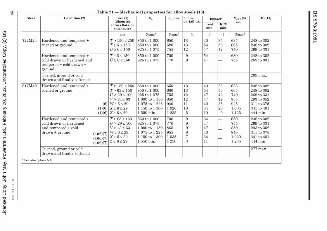
Table 21 — Mechanical properties for alloy steels (18)Steel Condition (2) Size (1)
(diameter across flats, or
thickness)
Rm Re min. A min.on 5.65√So
Impacta Rp0.2 (3) min.
HB (13)
Izod min.
KCV min.
mm N/mm2 N/mm2 % J J N/mm2
530M40 Hardened and tempered +turned or ground
R > 63 ≤ 100S ≥ 6 ≤ 63T ≥ 6 ≤ 29
700 to 850775 to 925850 to 1 000
525585680
171513
545454
505050
510570665
201 to 255223 to 277248 to 302
Hardened and tempered +cold drawn or hardened andtempered + cold drawn +ground
R > 63 ≤ 100S > 13 ≤ 63T ≥ 6 ≤ 29
700 to 850775 to 925850 to 1 000
540600700
1211
9
545454
———
525585680
201 to 255223 to 277248 to 302
Turned, ground or colddrawn and finally softened
229 max.
605M36 Hardened and tempered +turned or ground
R >150 ≤ 250R > 29 ≤ 150S > 13 ≤ 100T ≥ 6 ≤ 63U ≥ 6 ≤ 29V ≥ 6 ≤ 19
700 to 850700 to 850775 to 925850 to 1 000925 to 1 0751 000 to 1 150
495525585680755850
151715131212
345454544747
285050504242
480510570665740835
201 to 255201 to 255223 to 277248 to 302269 to 331293 to 352
Hardened and tempered +cold drawn or hardened andtempered + cold drawn +ground
R > 29 ≤ 150S > 13 ≤ 100T ≥ 6 ≤ 63U ≥ 6 ≤ 29V ≥ 6 ≤ 19
700 to 850775 to 925850 to 1 000925 to 1 0751 000 to 1 150
540600700770865
1211
999
5454544747
—————
525585680755850
201 to 255223 to 277248 to 302269 to 331293 to 352
Turned, ground or colddrawn and finally softened
241 max.
606M36 Hardened and tempered +turned or ground
R > 13 ≤ 100S ≥ 6 ≤ 63T ≥ 6 ≤ 29
700 to 850775 to 925850 to 1 000
525585680
151311
544740
504235
510570665
201 to 255223 to 277248 to 302
Hardened and tempered +cold drawn or hardened andtempered + cold drawn +ground
R > 29 ≤ 100S ≥ 6 ≤ 63T ≥ 6 ≤ 29
700 to 850775 to 925850 to 1 000
540600700
1110
8
474740
———
525585680
201 to 255223 to 277248 to 302
Turned, ground or colddrawn and finally softened
229 max.
a See also option A.3.
Lice
nsed
Cop
y: J
ohn
May
, Pow
ertr
ain
Ltd.
, Feb
ruar
y 20
, 200
2, U
ncon
trol
led
Cop
y, (
c) B
SI

BS
970-3:1991
© B
SI 11-1998
19
Table 21 — Mechanical properties for alloy steels (18)Steel Condition (2) Size (1)
(diameter across flats, or
thickness)
Rm Re min. A min. on 5.65 √So
Impacta Rp0.2 (3) min.
HB (13)
Izod min.
KCV min.
mm N/mm2 N/mm2 % J J N/mm2
708M40 Hardened and tempered +turned or ground
(4)(6)
R > 150 ≤ 250R > 63 ≤ 150S > 29 ≤ 100T ≥ 6 ≤ 63U ≥ 6 ≤ 29V ≥ 6 ≤ 19W ≥ 6 ≤ 13
700 to 850700 to 850775 to 925850 to 1 000925 to 1 0751 000 to 1 1501 075 to 1 225
495525585680755850940
15171513121212
34545454474740
28505050424235
480510570665740835925
201 to 255201 to 255223 to 277248 to 302269 to 331293 to 352311 to 375
Hardened and tempered +cold drawn or hardened +tempered + cold drawn +ground
(4)(6)
R > 63 ≤ 150S > 29 ≤ 100T ≥ 6 ≤ 63U ≥ 6 ≤ 29V ≥ 6 ≤ 19W ≥ 6 ≤ 13
700 to 850775 to 925850 to 1 000925 to 1 0751 000 to 1 1501 075 to 1 225
540600700770865955
1211
9998
545454474740
—————
525585680755850940
201 to 255223 to 277248 to 302269 to 331293 to 352311 to 375
Turned, ground or colddrawn and finally softened
248 max.
709M40 Hardened and tempered +turned or ground
(4)(6)(6)
R > 100 ≤ 250S > 150 ≤ 250S > 63 ≤ 150T > 29 ≤ 100U > 13 ≤ 63V ≥ 6 ≤ 29W ≥ 6 ≤ 19
700 to 850775 to 925775 to 925850 to 1 000925 to 1 0751 000 to 1 1501 075 to 1 225
495555585680755850940
15131513121212
34275454474740
28225050424235
480540570665740835925
201 to 255223 to 277223 to 277248 to 302269 to 331293 to 352311 to 375
Hardened and tempered +cold drawn or hardened and tempered + cold drawn +ground
(4)(6)
R > 100 ≤ 150S > 63 ≤ 150T > 29 ≤ 100U > 13 ≤ 63V ≥ 6 ≤ 29W ≥ 6 ≤ 19
700 to 850775 to 925850 to 1 000925 to 1 0751 000 to 1 1501 075 to 1 225
540600700770865955
1111
9998
545454474740
——————
510585680755850940
201 to 255223 to 277248 to 302269 to 331293 to 352311 to 375
Turned, ground or colddrawn and finally softened
255 max.
a See also option A.3.
Lice
nsed
Cop
y: J
ohn
May
, Pow
ertr
ain
Ltd.
, Feb
ruar
y 20
, 200
2, U
ncon
trol
led
Cop
y, (
c) B
SI
BS
970-3:1991
20©
BS
I 11-1998
Table 21 — Mechanical properties for alloy steels (18)
Steel Condition (2) Size (1) (diameter
across flats, or thickness)
Rm Re min. A min. on 5.65 √So
Impacta Rp0.2 (3) min.
HB (13)
Izod min.
KCV min.
mm N/mm2 N/mm2 % J J N/mm2
722M24 Hardened and tempered +turned or ground
T > 150 ≤ 250T ≥ 6 ≤ 150U ≥ 6 ≤ 150
850 to 1 000850 to 1 000925 to 1 075
650680755
131312
405447
355042
635665740
248 to 302248 to 302269 to 331
Hardened and tempered +cold drawn or hardened andtempered + cold drawn +ground
T ≥ 6 ≤ 150U ≥ 6 ≤ 150
850 to 1 000925 to 1 075
700770
99
5447
——
680755
248 to 302269 to 331
Turned, ground or colddrawn and finally softened
269 max.
817M40 Hardened and tempered +turned or ground
(6)(1)(6)(1)(6)
T > 150 ≤ 250T > 63 ≤ 150U > 29 ≤ 100V > 13 ≤ 63W ≥ 6 ≤ 29X ≥ 6 ≤ 29Z ≥ 6 ≤ 29
850 to 1 000850 to 1 000925 to 1 0751 000 to 1 1501 075 to 1 2251 150 to 1 3001 550 min.
6506807558509401 0201 235
131312121110
5
40544747403410
355042423528
9
6356657408359251 0051 125
248 to 302248 to 302269 to 331293 to 352311 to 375341 to 401444 min.
Hardened and tempered +cold drawn or hardened and tempered + cold drawn + ground (4)(6)(7)
(4)(6)(7)(4)(6)(7)
T > 63 ≤ 150U > 29 ≤ 100V > 13 ≤ 63W ≥ 6 ≤ 29X ≥ 6 ≤ 29Z ≥ 6 ≤ 29
850 to 1 000925 to 1 0751 000 to 1 1501 075 to 1 2251 150 to 1 3001 550 min.
7007708659551 0351 250
999873
544747403411
——————
6807558509401 0201 235
248 to 302269 to 331293 to 352311 to 375341 to 401444 min.
Turned, ground or colddrawn and finally softened
277 max.
a See also option A.3.
Lice
nsed
Cop
y: J
ohn
May
, Pow
ertr
ain
Ltd.
, Feb
ruar
y 20
, 200
2, U
ncon
trol
led
Cop
y, (
c) B
SI

BS
970-3:1991
© B
SI 11-1998
21
Table 21 — Mechanical properties for alloy steels (18)Steel Condition (2) Size (1)
(diameter across flats, or
thickness)
Rm Re min. A min.on 5.65 √So
Impacta Rp0.2 (3) min.
HB (13)
Izod min.
KCV min.
mm N/mm2 N/mm2 % J J N/mm2
826M31 Hardened and tempered and turned or ground
(6)(6)(6)
T > 150 ≤ 250T > 100 ≤ 150U > 150 ≤ 250U > 100 ≤ 150V > 63 ≤ 150W > 29 ≤ 100X > 13 ≤ 63Z > 13 ≤ 63
850 to 1 000850 to 1 000925 to 1 075925 to 1 0751 000 to 1 1501 075 to 1 2251 150 to 1 3001 550 min.
6506807407558509401 0201 235
13131212121110
5
4054344747403410
35502842423528
9
6356657257408359251 0051 125
248 to 302248 to 302269 to 331269 to 331293 to 352311 to 375341 to 401444 min.
Hardened and tempered and cold drawn or hardened and tempered and cold drawn and ground (4)(6)(7)
(4)(6)(7)(4)(6)(7)
T > 63 ≤ 150U > 29 ≤ 100V > 29 ≤ 100W > 29 ≤ 100X > 6 ≤ 63Z > 6 ≤ 63
850 to 1 000925 to 1 0751 000 to 1 1501 075 to 1 2251 150 to 1 3001 550 min.
7007708859551 0351 250
999873
544747403410
——————
6807558509401 0201 235
248 to 302269 to 331293 to 362311 to 375341 to 401444 min.
Turned, ground or colddrawn and finally softened
— — — — — — — 277 max.
826M40 Hardened and tempered +turned or ground
(6)(6)(6)(6)(6)
U > 150 ≤ 250U > 100 ≤ 150V > 63 ≤ 250V > 63 ≤ 150W > 29 ≤ 250W > 29 ≤ 150X > 29 ≤ 150Y > 29 ≤ 150Z > 29 ≤ 100
925 to 1 075925 to 1 0751 000 to 1 1501 000 to 1 1501 075 to 1 2251 075 to 1 2251 150 to 1 3001 225 to 1 3751 550 min.
7407558358509259401 0201 0951 235
1212121211111010
7
344734472740343413
284228422235282811
7257408208359109251 0051 0801 125
269 to 331269 to 331293 to 352293 to 352311 to 375311 to 375341 to 401363 to 429444 min. (4)
Hardened and tempered +cold drawn or hardened and tempered + cold drawn + ground (1)(4)(6)(7)
(1)(4)(6)(7)(1)(4)(6)(7)
U > 100 ≤ 150V > 63 ≤ 150W > 29 ≤ 150X > 29 ≤ 150Y > 29 ≤ 150Z > 29 ≤ 100
925 to 1 0751 000 to 1 1501 075 to 1 2251 150 to 1 3001 225 to 1 3751 550 min. (12)
7708659551 0351 1101 250
998775
474740343413
——————
7558509401 0201 0951 235
269 to 331 293 to 352311 to 375341 to 401363 to 429444 min.
Turned, ground or colddrawn and finally softened
277 max.
a See also option A.3.Lice
nsed
Cop
y: J
ohn
May
, Pow
ertr
ain
Ltd.
, Feb
ruar
y 20
, 200
2, U
ncon
trol
led
Cop
y, (
c) B
SI

BS
970-3:1991
22©
BS
I 11-1998
Table 21 — Mechanical properties for alloy steels (18)
Steel Condition (2) Size (1) (diameter across flats, or
thickness)
Rm Re min. A min. on 5.65 √So
Impacta Rp0.2 (3) min.
HB (13)
Izod min.
KCV min.
mm N/mm2 N/mm2 % J J N/mm2
945M38 Hardened and tempered + turned or ground
R > 150 ≤ 250R>100 ≤ 150S > 63 ≤ 100T > 29 ≤ 63U ≥ 6 ≤ 29V ≥ 6 ≤ 29
700 to 850700 to 850775 to 925850 to 1 000925 to 1 0751 000 to 1 150
495525585680755850
151715131212
345454544747
285050504242
480510570665740835
201 to 255201 to 255223 to 277248 to 302269 to 331293 to 352
Hardened and tempered + cold drawn or hardened and tempered + cold drawn + ground
R > 100 ≤ 150 S > 63 ≤ 100T > 29 ≤ 63U ≥ 6 ≤ 29V ≥ 6 ≤ 29
700 to 850775 to 925850 to 1 000925 to 1 0751 000 to 1 150
540 600700770865
13 1110
99
5454544747
5050504242
525585680755850
201 to 255223 to 277248 to 302269 to 331293 to 352
Turned, ground or cold drawn and finally softened
277 max.
a See also option A.3.
Lice
nsed
Cop
y: J
ohn
May
, Pow
ertr
ain
Ltd.
, Feb
ruar
y 20
, 200
2, U
ncon
trol
led
Cop
y, (
c) B
SI

BS
970-3:1991
© B
SI 11-1998
23
Table 22 — Mechanical properties for case hardening steelsSteel Test bar
diameterRm min. A min.
on 5.65 √SoImpacta HB (max.) (14)
normalizedHB max. (14) Hardening
Temperature
Izod min.
KCV min.
Subcritically annealed
Normalized and tempered
mm N/mm2 % J J °C
Carbon steels
045M10045A10080M15
1319 (5)1319 (5)29
430430490460430
1818161618
4747404040
4242353535
—————
—————
—————
—————
Carbon manganese steels
210M15 1319 (5)29
490460430
161618
404040
353535
———
———
———
———
Alloy steel
635M15637M17655M13655M17805M17805M20815M17820M17822M17835M15
19191919191919191919
7709301 0007707708501 0801 1601 3101 310
1210
9121211
8888
27204040272027272734
22163535221622222228
207217—207207207————
——255———255269269277
——223———241248255269
820 to 840820 to 840800 to 820820 to 840820 to 840820 to 840820 to 840820 to 840820 to 840800 to 820b
a See also option A.3.b Also to be stress relieved at not greater than 200 °C.NOTE Mechanical tests are in the blank carburized condition. Hardness figures are in the condition stated.
Lice
nsed
Cop
y: J
ohn
May
, Pow
ertr
ain
Ltd.
, Feb
ruar
y 20
, 200
2, U
ncon
trol
led
Cop
y, (
c) B
SI

BS
970-3:1991
24©
BS
I 11-1998
Table 23 — Heat treatment and mechanical properties for ferritic and martensitic stainless and heat resisting steels (18)Steel Softened
condition HB max.
Heat treatment condition
LRS Heat treatment Rm Re min. A min. on 5.65 √So
Impacta Rp0.2 (3) min.
HB
Izod min.
KCV min.
mm °C N/mm2 N/mm2 % J J N/mm2
Ferritic steels403S17430S17
170170
——
15063
700 to 780 (16)750 to 820 (17)
420 min.430 min.
280280
2020
——
——
245245
170 max.170 max.
Martensitic steels410S21 207 950 to 1 020
(10)P 150 650 to 750 (11) 550 to 700 370 20 < 63 mm: 54
≥ 63 mm: 34— 340 152 to 207
R 63 600 to 700 (11) 700 to 850 525 15 — 495 201 to 255416S21 207 950 to 1 020
PR
15063
650 to 750600 to 700 (11)
550 to 700700 to 850
370525
1511
3427
——
340495
152 to 207201 to 255
416S29 217 950 to 1 020(10)
RS
15029
650 to 750 (11)600 to 700 (11)
700 to 850775 to 925
525585
1110
2713
——
495555
201 to 255223 to 277
416S37 229 950 to 1 020(10)
RS
150150
650 to 750 (11)600 to 700 (11)
700 to 850775 to 925
525585
1110
2713
——
495555
201 to 255223 to 277
416S41 179 950 to 1 020(10)
PR
15063
650 to 750 (10)600 to 700 (11)
550 to 700700 to 850
370525
1511
3427
——
340495
152 to 207201 to 255
420S29 217 950 to 1 020(10)
R 150 650 to 750 (11) 700 to 850 525 15 < 63 mm: 34≥ 63 mm: 27
— 495 201 to 255
S 29 600 to 700 (11) 775 to 925 585 13 — 555 223 to 277
Lice
nsed
Cop
y: J
ohn
May
, Pow
ertr
ain
Ltd.
, Feb
ruar
y 20
, 200
2, U
ncon
trol
led
Cop
y, (
c) B
SI

BS
970-3:1991
© B
SI 11-1998
25
Table 23 — Heat treatment and mechanical properties for ferritic and martensitic stainless and heat resisting steels (18)Steel Softened
condition HB max.
Heat treatment condition
LRS Heat treatment Rm Re min. A min. on 5.65 √So
Impacta Rp0.2 (3) min.
HB
Izod min. KCV min.
mm °C N/mm2 N/mm2 % J J N/mm2
420S37 229 950 to 1 020(10)
R 150 650 to 750 (11) 700 to 850 525 15 < 63 mm: 34≥ 63 mm: 27
— 495 210 to 255
S 150 600 to 700 (11) 775 to 925 585 13 < 63 mm: 27≥ 63 mm: 14
— 555 223 to 277
431S29 277 950 to 1 020
T 150 550 to 650 850 to 1 000 680 11 < 63 mm: 34≥ 63 mm: 20
— 635 248 to 302
a See also option A.3.
Lice
nsed
Cop
y: J
ohn
May
, Pow
ertr
ain
Ltd.
, Feb
ruar
y 20
, 200
2, U
ncon
trol
led
Cop
y, (
c) B
SI

BS 970-3:1991
26 © BSI 11-1998
Table 24 — Softening treatment and mechanical properties for austenitic stainless and heat resisting steels in the finally softened conditiona (15)
Steel Rm min. A min. on 5.65 √So Rp0.2 (3) Rp1.0 min. Sensitization period (see 8.6)
N/mm2 % N/mm2 N/mm2 min
302S31304S11304S15304S31321S31347S31316S11316S13316S31316S33320S31310S31303S31303S42325S31
510480480490510510490490510510510510510510510
404040403530404040403540404035
190180195195200205190190205205210205190190200
225215230230235240225225240240245240225225235
—30151530303030151530———30
a These figures are applicable to sections up to 160 mm softened at 1 000 °C to 1 100 °C.
Lice
nsed
Cop
y: J
ohn
May
, Pow
ertr
ain
Ltd.
, Feb
ruar
y 20
, 200
2, U
ncon
trol
led
Cop
y, (
c) B
SI

BS 970-3:1991
© BSI 11-1998 27
Table 25 — Mechanical properties for austenitic stainless steels in the cold drawn
condition (15)
Table 26 — Mechanical properties for austenitic stainless steels in the softened and
finally cold drawn condition (15)
Table 27 — Normalizing for carbon and carbon manganese steels
Section Rm min. A min. on 5.65 √So
Rp0.2 min. Rp1.0 min.
mm N/mm2 % N/mm2 N/mm2
≤ 19> 19 ≤ 25> 25 ≤ 32> 32 ≤ 38> 38 ≤ 45
865790725695650
1215202828
695555450340310
725585480370340
Section Rm min. A min. on 5.65 √So
Rp0.2 min. Rp1.0 min.
mm N/mm2 % N/mm2 N/mm2
≤ 19> 19
600550
1520
375325
425375
Steel Normalizing temperature
°C
080M15070M20080M30080M40080M50070M55150M19150M36
890 to 920880 to 910860 to 890830 to 860810 to 840810 to 840860 to 900840 to 870
Lice
nsed
Cop
y: J
ohn
May
, Pow
ertr
ain
Ltd.
, Feb
ruar
y 20
, 200
2, U
ncon
trol
led
Cop
y, (
c) B
SI

BS 970-3:1991
28 © BSI 11-1998
Table 28 — Hardening and tempering parameters for free-cutting, carbon and carbon manganese, and alloy steels
Notes to Table 12 to Table 28 1) For cold drawn bar of a diameter or across flat section of less than 6 mm all mechanical properties should be agreed at the time of enquiry and/or order.2) Normalizing temperatures and hardening and tempering temperatures are given in Table 27 and Table 28.3) When specifically ordered.4) Properties cannot always be obtainable by bulk heat treatment of bar but these properties can be achieved by the appropriate heat treatment of components by the purchaser. 5) Preferred size.6) Often ordered in the softened condition for machining and subsequent heat treatment to achieve these specified mechanical properties. 7) Cold drawn bars are not normally available in this tensile strength range. 8) A maximum silicon content can be agreed between the purchaser and the supplier.9) Optional addition. 10) Oil or air hardened.11) Tempered. 12) When 0.2 % proof stress is specified it is recommended that a double tempering treatment be used:
a) 640 °C to 680 °C followed byb) 590 °C to 610 °C
13) Brinell hardness for guidance only except where material is supplied in the softened condition.14) Maximum hardness HB (when specified on the order) in the condition of delivery.15) For magnetic properties see also option A.2.16) Air cooled or furnace cooled.17) Cooled freely in air.18) The various tensile strength ranges for the different specifications have been designated with the reference symbol P to Z, as given in Table 29.
Steel Hardening treatment Tempering temperature
Temperature Quench medium
°C °C
080M30080M40080M50070M5150M19150M36212M36226M44530M40605M36606M36709M40722M24817M40826M40945M38
860 to 890830 to 860810 to 840810 to 840860 to 900840 to 870840 to 870830 to 860850 to 880840 to 870840 to 870860 to 890880 to 910820 to 850820 to 850840 to 870
Oil or waterOilOilOilOil or waterOilOilOilOilOilOilOilOilOilOilOil
550 to 660550 to 660550 to 660550 to 660550 to 660550 to 660550 to 660550 to 660550 to 700550 to 680550 to 680550 to 700550 to 700660 max.a
660 max.a
550 to 680a For these steels the temperature range 280 °C to 500 °C has to be avoided.
Lice
nsed
Cop
y: J
ohn
May
, Pow
ertr
ain
Ltd.
, Feb
ruar
y 20
, 200
2, U
ncon
trol
led
Cop
y, (
c) B
SI

BS 970-3:1991
© BSI 11-1998 29
Table 29 — Reference symbols for tensile strength ranges of hardened and tempered
materialReference symbol Tensile strengtha
N/mm2
PQRSTUVWXYZ
550 to 700625 to 775700 to 850775 to 925850 to 1 000925 to 1 0751 000 to 1 1501 075 to 1 2251 150 to 1 3001 225 to 1 3751 550 min.
a 1 N/mm2 = 1 MPaNOTE Other mechanical properties associated with these ranges are as indicated in the relevant tables.
Lice
nsed
Cop
y: J
ohn
May
, Pow
ertr
ain
Ltd.
, Feb
ruar
y 20
, 200
2, U
ncon
trol
led
Cop
y, (
c) B
SI

BS 970-3:1991
30 © BSI 11-1998
Appendix A OptionsNOTE These options may be agreed at the time of enquiry and/or order.
A.1 Hardness tests shall be required for bars supplied in the non-heat treated condition (see 4.2).A.2 Certification giving chemical analysis and/or mechanical properties and/or hardenability values shall be supplied (see 4.5).A.3 If the standard impact test specified inBS 131-1 is not required KCV values shall be specified (see 8.2).A.4 An intercrystalline corrosion test for stainless steels shall be carried out for each cast of steel supplied. If specified a bend test sample shall be prepared and tested in accordance with BS 5903. It shall be sensitized by heating at a temperatureof 650 °C for the time specified, followed by cooling in still air. The other provisions of BS 5903 shall apply (see 8.6).A.5 Where steels containing lead are required, the lead range shall be stated in the order. If not specifically stated the lead content shall be not less than 0.15 % and not greater than 0.35 % on cast analysis (see 9.1 and 9.3).
Lice
nsed
Cop
y: J
ohn
May
, Pow
ertr
ain
Ltd.
, Feb
ruar
y 20
, 200
2, U
ncon
trol
led
Cop
y, (
c) B
SI

BS 970-3:1991
© BSI 11-1998
Publication(s) referred to:
BS 131, Notched bar tests.BS 131-1, The Izod impact test on metals.BS 240, Method for Brinell hardness test and for verification of Brinell hardness testing machines.BS 970, Specification for wrought steels for mechanical and allied engineering purposes.BS 970-1, General inspection and testing procedures and specific requirements for carbon, carbon manganese, alloy and stainless steels.BS 1134, Assessment of surface texture.BS 1134-1, Methods and instrumentation.BS 4437, Method for determining hardenability of steel by end quenching (Jominy test).BS 4490, Methods for micrographic determination of the grain size of steel.BS 5903, Method for determination of resistance to intergranular corrosion of austenitic stainless steels: copper sulphate-sulphuric acid method (Moneypenny Strauss test).BS 6200, Sampling and analysis of iron, steel and other ferrous metals.BS 6200-3, Methods of analysis.BS 6617, Determination of decarburization in steel.BS 6617-1, Methods for determining decarburization by microscopic and micro-hardness techniques.BS 6617-2, Methods for determining decarburization by chemical and spectrographic analysis techniques.BS Handbook 19, Methods for the sampling and analysis of iron, steel and other ferrous metals.BS EN 10002-1, Tensile testing of metallic materials — Part 1: Method of test at ambient temperature.
Lice
nsed
Cop
y: J
ohn
May
, Pow
ertr
ain
Ltd.
, Feb
ruar
y 20
, 200
2, U
ncon
trol
led
Cop
y, (
c) B
SI

BSI389 Chiswick High RoadLondonW4 4AL
|||||||||||||||||||||||||||||||||||||||||||||||||||||||||||||||||||||||||||||||||||||||||||||||||||||||||||||||||||||||||||||||
BSI Ð British Standards Institution
BSI is the independent national body responsible for preparing British Standards. Itpresents the UK view on standards in Europe and at the international level. It isincorporated by Royal Charter.
Revisions
British Standards are updated by amendment or revision. Users of British Standardsshould make sure that they possess the latest amendments or editions.
It is the constant aim of BSI to improve the quality of our products and services. Wewould be grateful if anyone finding an inaccuracy or ambiguity while using thisBritish Standard would inform the Secretary of the technical committee responsible,the identity of which can be found on the inside front cover. Tel: 020 8996 9000.Fax: 020 8996 7400.
BSI offers members an individual updating service called PLUS which ensures thatsubscribers automatically receive the latest editions of standards.
Buying standards
Orders for all BSI, international and foreign standards publications should beaddressed to Customer Services. Tel: 020 8996 9001. Fax: 020 8996 7001.
In response to orders for international standards, it is BSI policy to supply the BSIimplementation of those that have been published as British Standards, unlessotherwise requested.
Information on standards
BSI provides a wide range of information on national, European and internationalstandards through its Library and its Technical Help to Exporters Service. VariousBSI electronic information services are also available which give details on all itsproducts and services. Contact the Information Centre. Tel: 020 8996 7111.Fax: 020 8996 7048.
Subscribing members of BSI are kept up to date with standards developments andreceive substantial discounts on the purchase price of standards. For details ofthese and other benefits contact Membership Administration. Tel: 020 8996 7002.Fax: 020 8996 7001.
Copyright
Copyright subsists in all BSI publications. BSI also holds the copyright, in the UK, ofthe publications of the international standardization bodies. Except as permittedunder the Copyright, Designs and Patents Act 1988 no extract may be reproduced,stored in a retrieval system or transmitted in any form or by any means ± electronic,photocopying, recording or otherwise ± without prior written permission from BSI.
This does not preclude the free use, in the course of implementing the standard, ofnecessary details such as symbols, and size, type or grade designations. If thesedetails are to be used for any other purpose than implementation then the priorwritten permission of BSI must be obtained.
If permission is granted, the terms may include royalty payments or a licensingagreement. Details and advice can be obtained from the Copyright Manager.Tel: 020 8996 7070.
Lice
nsed
Cop
y: J
ohn
May
, Pow
ertr
ain
Ltd.
, Feb
ruar
y 20
, 200
2, U
ncon
trol
led
Cop
y, (
c) B
SI