Embed Size (px)
Citation preview

®
Application Note
Bowser/Stewart F7Tsunami Digital Sound Decoder Installation Notes
OverviewThis application note describes how to install a TSU-BW1000 digital sound decoder into a Bowser/Stewart HO-Scale F7.
Skill Level 2: The entire installation can be completed in one to two hours with no modification required to the model.
Bill of MaterialsStock No. Description
828020 TSU-BW1000 for EMD 567810129 0.91” Mega Bass Speaker
28 Gauge Wire
Evergreen P.N.
148 Styrene Strip 0.040” x 0.188” 9040 Sheet Styrene 0.040”
For your convenience, Evergreen part numbers have been listed above. Please visit their web site at www.evergreenscalemodels.com
Tools You Will Need■ Miniature Screwdriver Set■ Miniature Pliers■ X-acto Knife■ Wire Cutters■ Soldering Iron■ Rosin Core Solder■ Clear Silicone or Aquarium Sealant■ Masking Tape
■ Liquid Plastic Cement
Installation
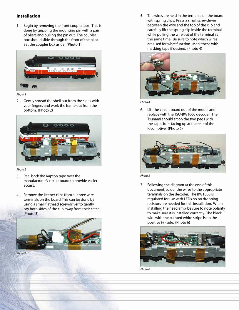
1. Begin by removing the front coupler box. This is done by gripping the mounting pin with a pair of pliers and pulling the pin out. The coupler box should slide through the front of the pilot. Set the coupler box aside. (Photo 1)
2. Gently spread the shell out from the sides with your fingers and work the frame out from the bottom. (Photo 2)
3. Peel back the Kapton tape over the manufacturer’s circuit board to provide easier access.
4. Remove the keeper clips from all three wire terminals on the board. This can be done by using a small flathead screwdriver to gently pry both sides of the clip away from their catch. (Photo 3)
5. The wires are held in the terminal on the board with spring clips. Press a small screwdriver between the wire and the top of the clip and carefully lift the spring clip inside the terminal while pulling the wire out of the terminal at the same time. Be sure to note which wires are used for what function. Mark these with masking tape if desired. (Photo 4)
6. Lift the circuit board out of the model and replace with the TSU-BW1000 decoder. The Tsunami should sit on the two pegs with the capacitors facing up at the rear of the locomotive. (Photo 5)
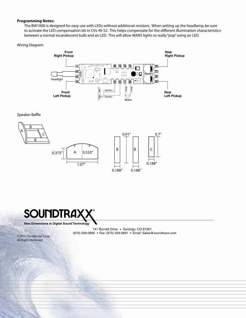
7. Following the diagram at the end of this document, solder the wires to the appropriate terminals on the decoder. The BW1000 is regulated for use with LEDs, so no dropping resistors are needed for this installation. When installing the headlamp, be sure to note polarity to make sure it is installed correctly. The black wire with the painted white stripe is on the positive (+) side. (Photo 6)
Photo 1
Photo 2
Photo 3
Photo 4
Photo 5
Photo 6
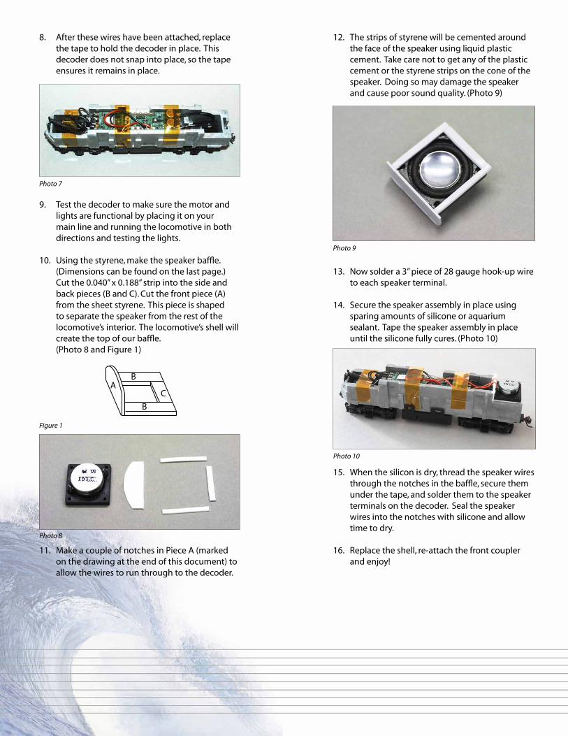
12. The strips of styrene will be cemented around the face of the speaker using liquid plastic cement. Take care not to get any of the plastic cement or the styrene strips on the cone of the speaker. Doing so may damage the speaker and cause poor sound quality. (Photo 9)
13. Now solder a 3” piece of 28 gauge hook-up wire to each speaker terminal.
14. Secure the speaker assembly in place using sparing amounts of silicone or aquarium sealant. Tape the speaker assembly in place until the silicone fully cures. (Photo 10)
15. When the silicon is dry, thread the speaker wires through the notches in the baffle, secure them under the tape, and solder them to the speaker terminals on the decoder. Seal the speaker wires into the notches with silicone and allow time to dry.
16. Replace the shell, re-attach the front coupler and enjoy!
8. After these wires have been attached, replace the tape to hold the decoder in place. This decoder does not snap into place, so the tape ensures it remains in place.
9. Test the decoder to make sure the motor and lights are functional by placing it on your main line and running the locomotive in both directions and testing the lights.
10. Using the styrene, make the speaker baffle. (Dimensions can be found on the last page.) Cut the 0.040” x 0.188” strip into the side and back pieces (B and C). Cut the front piece (A) from the sheet styrene. This piece is shaped to separate the speaker from the rest of the locomotive’s interior. The locomotive’s shell will create the top of our baffle. (Photo 8 and Figure 1)
11. Make a couple of notches in Piece A (marked on the drawing at the end of this document) to allow the wires to run through to the decoder.
Photo 7
Photo 8
Photo 9
Photo 10
0.535”
1.07”
0.375”
0.91”
0.188” 0.188”
0.188”
0.7”A
A
B
B
B
B
C
CFigure 1
141 Burnett Drive Durango, CO 81301 (970) 259-0690 Fax: (970) 259-0691 Email: [email protected]
®
New Dimensions in Digital Sound Technology
Programming Notes: The BW1000 is designed for easy use with LEDs without additional resistors. When setting up the headlamp, be sure
to activate the LED compensation bit in CVs 49-52. This helps compensate for the different illumination characteristics between a normal incandescent bulb and an LED. This will allow MARS lights to really “pop” using an LED.
Wiring Diagram
©2011 Throttle Up! Corp.All Rights Reserved
C15
C18
++
Front Right Pickup
Front Left Pickup
RearRight Pickup
RearLeft Pickup
Headlight5 6 7 8
Speaker +
Speaker -
Motor
Motor -
Motor +
1 2 3 4 9
10
11
12
F5
F6
S+
S-
M-
M+
16 15 14 13
FRONT
Speaker Baffle
0.535”
1.07”
0.375”
0.91”
0.188” 0.188”
0.188”
0.7”A
A
B
B
B
B
C
C