Embed Size (px)
Citation preview

LIBRODEINGENIERÍA
LIBRODEINGENIERIA
9Zh^\c BVcjVa
EaVhi^X A^cZY E^eZ VcY ;^ii^c\h


2
About Crane ChemPharma Flow SolutionsTM
CRANE ChemPharma Flow Solutions™ designs and manufactures a variety of high performance products including: sleeved plug valves, lined valves, high performance butterfly valves, aseptic and industrial diaphragm valves, actuation, lined pipe, fittings and hoses, and air operated diaphragm and peristaltic pumps. Our trusted brands Saunders®, XOMOX®, DEPA®, ELRO, Revo®, Resistoflex®, and ResistoPure® offer our customers complete and innovative fluid handling solutions designed for the most demanding corrosive, erosive and high purity applications within the chemical, bio-technology and pharmaceutical industries.
Marion, NC USA Pforzheim, Germany Singapore
Shanghai, China The Netherlands
About Resistoflex®
Resistoflex started manufacturing polyvinyl alcohol (PVA) lined braided hose in New Jersey in 1936. Resistoflex invented the PTFE lined hose technology in 1953 for the aerospace and chemical industries, and in 1956 introduced the world’s first pipe and fittings lined with Teflon® PTFE. Resistoflex later developed pipe and fittings lined with PVDF, polypropylene, PFA, and custom fittings lined with Tefzel® ETFE.
Resistoflex corrosion-resistant plastic lined pipe, fittings, and Teflon® lined hoses are used in corrosive fluid services as an economical alternative to expensive alloys. Resistoflex products are available worldwide with manufacturing and sales locations in North America, Europe, and Asia.
The information contained herein is provided only as a guide for the use of Resistoflex products and does not constitute an express warranty of any kind. Resistoflex specifically disclaims the implied warranty of merchantability and fitness for a particular purpose.
Teflon® and Tefzel® are registered trademarks of DuPont.
3
Table of Contents
About Resistoflex. .................................................................................................... 2 Terminology and Standards ..................................................................................... 4 Resistoflex Distribution Network .............................................................................. 5 The Thermalok Process .......................................................................................... 6 The Swaging Process. ............................................................................................. 7 Standard Material Specifications ............................................................................. 8 Standard and Custom Coatings .............................................................................. 9 Flange, Pipe, and Liner Data ................................................................................. 10 Pressure and Vacuum Capabilities ......................................................................... 11 Pipe Spool Dimensions ......................................................................................... 12 Minimum Flanged Spool Lengths .......................................................................... 13 90 Degree Elbows .......................................................................................... 14 - 15 Special Angle Elbows ............................................................................................ 15 45 Degree Elbows ................................................................................................. 16 Equal Tees ............................................................................................................. 17 Reducing Tees ................................................................................................ 18 - 19 Crosses ................................................................................................................. 20 Short Stack Tees and Crosses .............................................................................. 21 Instrument Tees .............................................................................................. 22 - 24 Strainer Tee Assembly ........................................................................................... 25 Lugged Body Instrument Tees ........................................................................ 26 - 28 45 Degree Laterals ................................................................................................ 29 Concentric Reducers ...................................................................................... 30 - 31 Eccentric Reducers ............................................................................................... 32 Ductile Iron Reducing Filler Flanges. ..................................................................... 33 Carbon Steel Reducing Filler Flanges ............................................................ 34 - 39 Blind Flanges ......................................................................................................... 40 Spectacle Blind Flanges ........................................................................................ 41 Lined Ring Spacers ............................................................................................... 41 Solid Plastic Spacers ............................................................................................. 42 Bull's Eye Sight Indicators ..................................................................................... 43 90 Degree Elbows ................................................................................................. 44 Reducing 90 Degree Elbows ................................................................................. 45 45 Degree Elbows ................................................................................................. 46 Equal Tees ............................................................................................................. 47 Reducing Tees ................................................................................................ 48 - 49 Strainer Tee ........................................................................................................... 50 Instrument Tees .............................................................................................. 51 - 53 Crosses ................................................................................................................. 54 45 Degree Laterals ................................................................................................ 55 Concentric Reducers ...................................................................................... 56 - 57 Eccentric Reducers ............................................................................................... 58 Reducing Filler Flanges .................................................................................. 59 - 60 Nozzle Liner. .......................................................................................................... 61 Thermowell Baffles ................................................................................................ 62 Reinforced Dip Pipes and Spargers ............................................................... 63 - 64 Reducing Filler Flanges for Dip Pipes ................................................................... 65 Solid PTFE Dip Pipes and Spargers ..................................................................... 66 PTFE Mixing Tee Nozzles ..................................................................................... 67 CONQUEST® Flangeless Piping System Design Considerations .................. 68 - 75 MultiAxis® Bent Piping ........................................................................................... 76 CONQUEST® Testing and Verification Data ................................................... 77 - 82 Joint Reduction Technologies - Life Cycle Cost Estimating ............................ 83 - 87 HIFTM Adapter .................................................................................................. 88 - 89 Pressure Drop Data ............................................................................................... 90 Flange Bolt Torquing and Pressure Testing .................................................... 91 - 92 Bolt Torque Requirements .............................................................................. 93 - 94 Bolt Length Requirements ..................................................................................... 95 Storage and Maintenance ..................................................................................... 96 Heat Tracing ................................................................................................... 97 - 98 Venting and Insulation ........................................................................................... 99
4
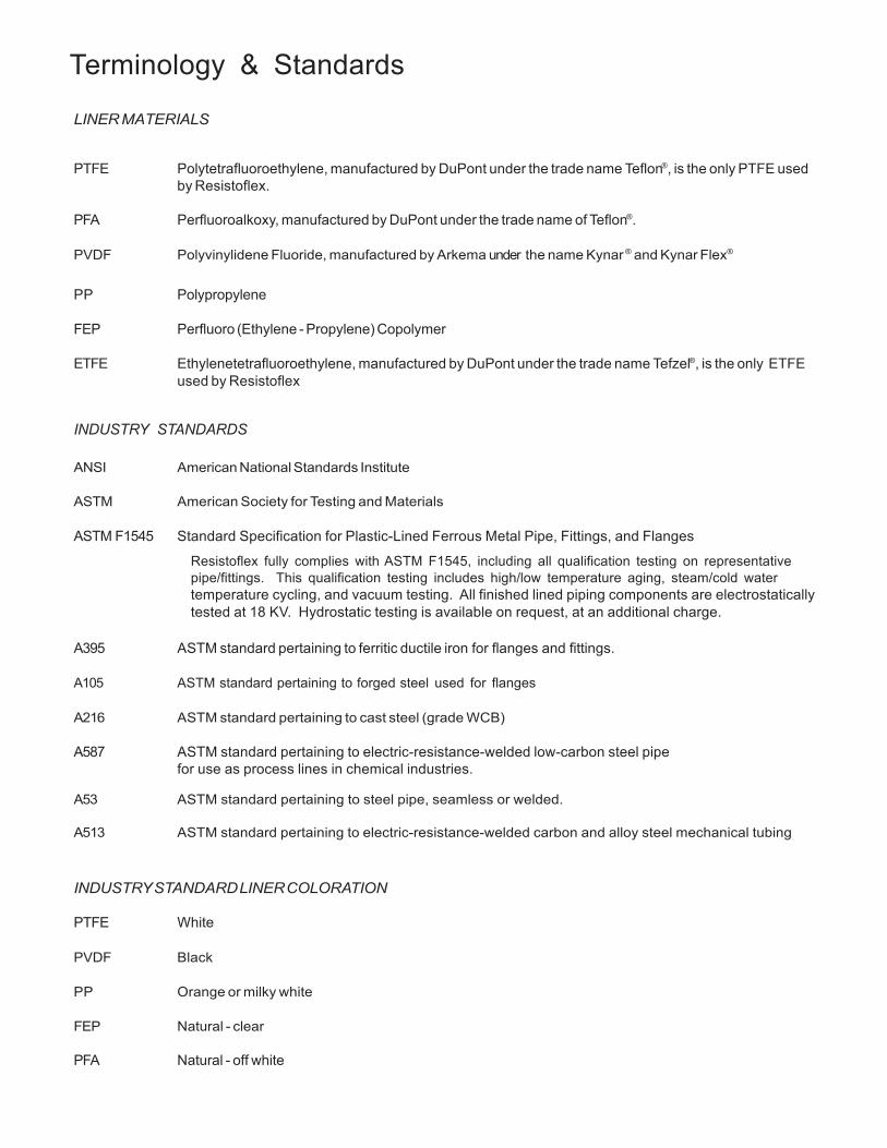
Terminology & Standards
LINER MATERIALS
PTFE Polytetrafluoroethylene, manufactured by DuPont under the trade name Teflon®, is the only PTFE used by Resistoflex.
PFA Perfluoroalkoxy, manufactured by DuPont under the trade name of Teflon®.
PVDF Polyvinylidene Fluoride, manufactured by Arkema under the name Kynar ® and Kynar Flex®
PP Polypropylene
FEP Perfluoro (Ethylene - Propylene) Copolymer
ETFE Ethylenetetrafluoroethylene, manufactured by DuPont under the trade name Tefzel®, is the only ETFE used by Resistoflex
INDUSTRY STANDARDS
ANSI American National Standards Institute
ASTM American Society for Testing and Materials
ASTM F1545 Standard Specification for Plastic-Lined Ferrous Metal Pipe, Fittings, and Flanges
Resistoflex fully complies with ASTM F1545, including all qualification testing on representative pipe/fittings. This qualification testing includes high/low temperature aging, steam/cold water temperature cycling, and vacuum testing. All finished lined piping components are electrostatically tested at 18 KV. Hydrostatic testing is available on request, at an additional charge.
A395 ASTM standard pertaining to ferritic ductile iron for flanges and fittings.
A105 ASTM standard pertaining to forged steel used for flanges
A216 ASTM standard pertaining to cast steel (grade WCB)
A587 ASTM standard pertaining to electric-resistance-welded low-carbon steel pipe for use as process lines in chemical industries.
A53 ASTM standard pertaining to steel pipe, seamless or welded.
A513 ASTM standard pertaining to electric-resistance-welded carbon and alloy steel mechanical tubing
INDUSTRY STANDARD LINER COLORATION
PTFE White
PVDF Black
PP Orange or milky white
FEP Natural - clear
PFA Natural - off white
ETFE Natural - shiny, milky white
5
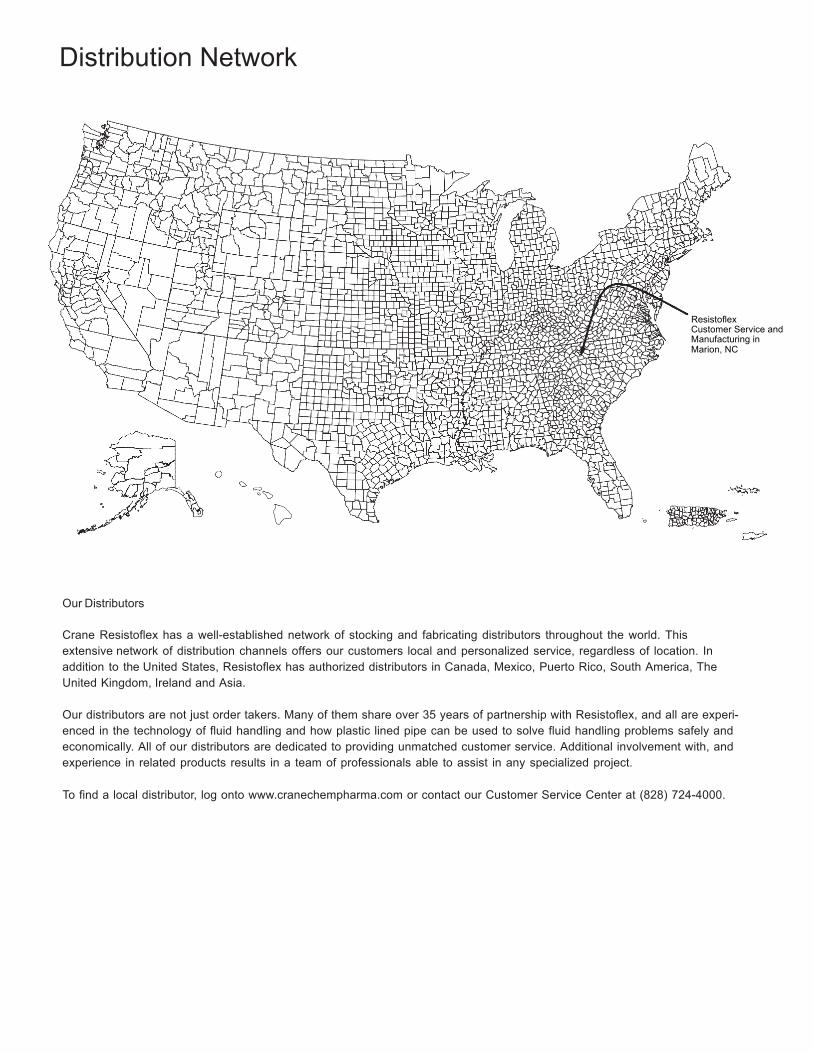
Distribution Network
Resistoflex Customer Service and Manufacturing in Marion, NC
Our Distributors
Crane Resistoflex has a well-established network of stocking and fabricating distributors throughout the world. This extensive network of distribution channels offers our customers local and personalized service, regardless of location. In addition to the United States, Resistoflex has authorized distributors in Canada, Mexico, Puerto Rico, South America, The United Kingdom, Ireland and Asia.
Our distributors are not just order takers. Many of them share over 35 years of partnership with Resistoflex, and all are experi- enced in the technology of fluid handling and how plastic lined pipe can be used to solve fluid handling problems safely and economically. All of our distributors are dedicated to providing unmatched customer service. Additional involvement with, and experience in related products results in a team of professionals able to assist in any specialized project.
To find a local distributor, log onto www.cranechempharma.com or contact our Customer Service Center at (828) 724-4000.
6
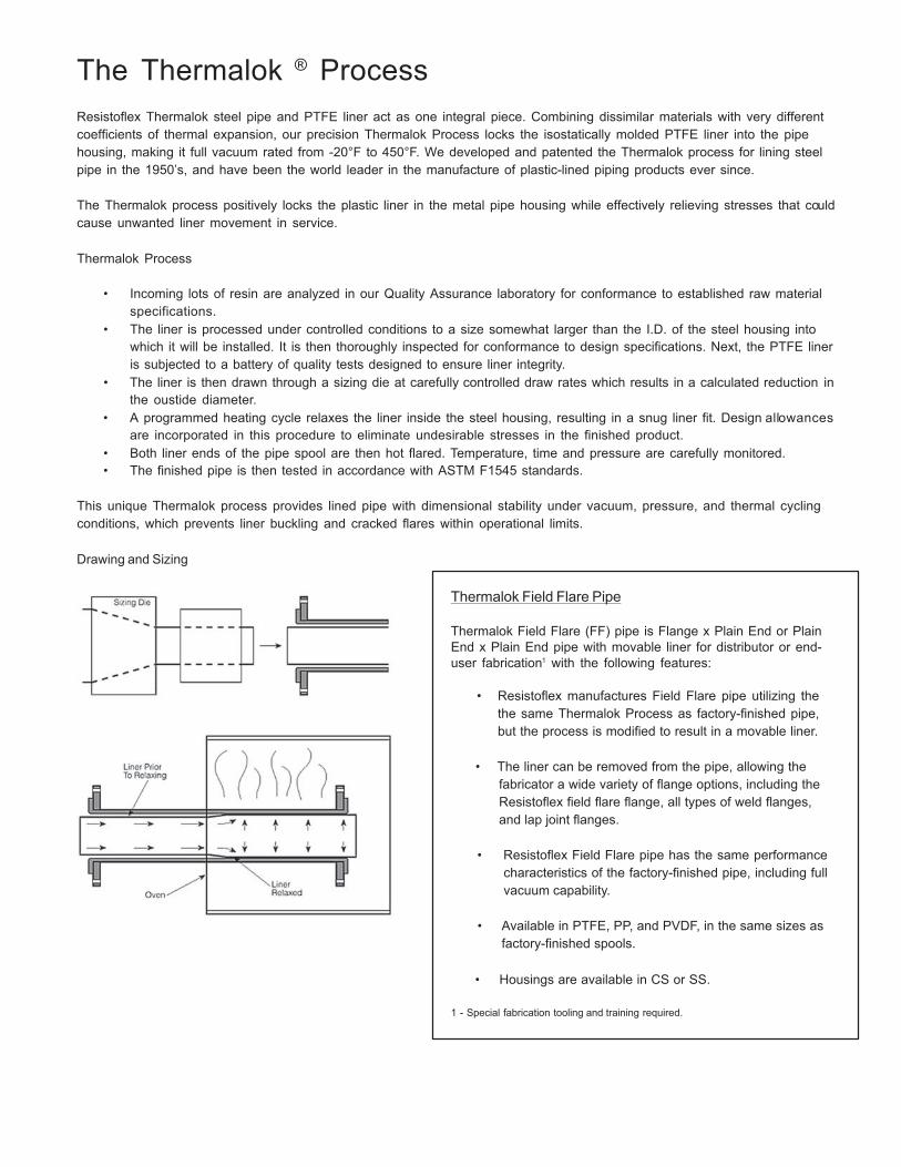
The Thermalok ® Process
Resistoflex Thermalok steel pipe and PTFE liner act as one integral piece. Combining dissimilar materials with very different coefficients of thermal expansion, our precision Thermalok Process locks the isostatically molded PTFE liner into the pipe housing, making it full vacuum rated from -20°F to 450°F. We developed and patented the Thermalok process for lining steel pipe in the 1950’s, and have been the world leader in the manufacture of plastic-lined piping products ever since.
The Thermalok process positively locks the plastic liner in the metal pipe housing while effectively relieving stresses that could cause unwanted liner movement in service.
Thermalok Process
• Incoming lots of resin are analyzed in our Quality Assurance laboratory for conformance to established raw material
specifications. • The liner is processed under controlled conditions to a size somewhat larger than the I.D. of the steel housing into
which it will be installed. It is then thoroughly inspected for conformance to design specifications. Next, the PTFE liner is subjected to a battery of quality tests designed to ensure liner integrity.
• The liner is then drawn through a sizing die at carefully controlled draw rates which results in a calculated reduction in the oustide diameter.
• A programmed heating cycle relaxes the liner inside the steel housing, resulting in a snug liner fit. Design allowances are incorporated in this procedure to eliminate undesirable stresses in the finished product.
• Both liner ends of the pipe spool are then hot flared. Temperature, time and pressure are carefully monitored. • The finished pipe is then tested in accordance with ASTM F1545 standards.
This unique Thermalok process provides lined pipe with dimensional stability under vacuum, pressure, and thermal cycling conditions, which prevents liner buckling and cracked flares within operational limits.
Drawing and Sizing
Thermalok Field Flare Pipe
Thermalok Field Flare (FF) pipe is Flange x Plain End or Plain End x Plain End pipe with movable liner for distributor or end- user fabrication1 with the following features:
• Resistoflex manufactures Field Flare pipe utilizing the
the same Thermalok Process as factory-finished pipe, but the process is modified to result in a movable liner.
• The liner can be removed from the pipe, allowing the
fabricator a wide variety of flange options, including the Resistoflex field flare flange, all types of weld flanges, and lap joint flanges.
• Resistoflex Field Flare pipe has the same performance
characteristics of the factory-finished pipe, including full vacuum capability.
• Available in PTFE, PP, and PVDF, in the same sizes as
factory-finished spools.
• Housings are available in CS or SS.
1 - Special fabrication tooling and training required.
7
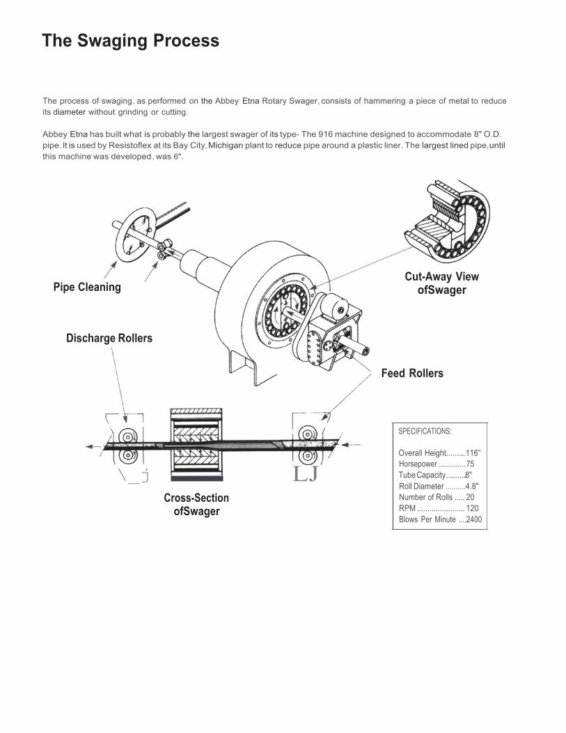
The Swaging Process
The process of swaging, as performed on the Abbey Etna Rotary Swager, consists of hammering a piece of metal to reduce its diameter without grinding or cutting.
Abbey Etna has built what is probably the largest swager of its type- The 916 machine designed to accommodate 8" O.D. pipe. lt is used by Resistoflex at its Bay City, Michigan plant to reduce pipe around a plastic liner. The largest lined pipe,until this machine was developed, was 6".
Pipe Cleaning
Discharge Rollers
\_j LJ
Cross-Section ofSwager
Cut-Away View ofSwager
Feed Rollers
SPECIFICATIONS:
Overall Height..........116" Horsepower .............. 75 Tube Capacity ...........8" Roll Diameter ..........4.8" Number of Rolls ..... 20 RPM ....................... 120 Blows Per Minute ....2400
8
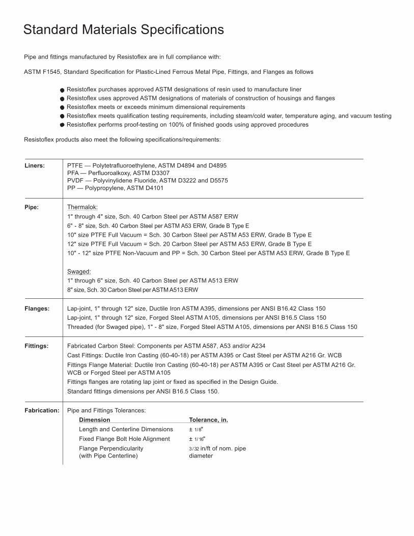
Standard Materials Specifications
Pipe and fittings manufactured by Resistoflex are in full compliance with:
ASTM F1545, Standard Specification for Plastic-Lined Ferrous Metal Pipe, Fittings, and Flanges as follows
Resistoflex purchases approved ASTM designations of resin used to manufacture liner Resistoflex uses approved ASTM designations of materials of construction of housings and flanges Resistoflex meets or exceeds minimum dimensional requirements Resistoflex meets qualification testing requirements, including steam/cold water, temperature aging, and vacuum testing Resistoflex performs proof-testing on 100% of finished goods using approved procedures
Resistoflex products also meet the following specifications/requirements:
Liners: PTFE — Polytetrafluoroethylene, ASTM D4894 and D4895 PFA — Perfluoroalkoxy, ASTM D3307 PVDF — Polyvinylidene Fluoride, ASTM D3222 and D5575 PP — Polypropylene, ASTM D4101
Pipe: Thermalok: 1" through 4" size, Sch. 40 Carbon Steel per ASTM A587 ERW 6" - 8" size, Sch. 40 Carbon Steel per ASTM A53 ERW, Grade B Type E 10" size PTFE Full Vacuum = Sch. 30 Carbon Steel per ASTM A53 ERW, Grade B Type E 12" size PTFE Full Vacuum = Sch. 20 Carbon Steel per ASTM A53 ERW, Grade B Type E 10" - 12" size PTFE Non-Vacuum and PP = Sch. 30 Carbon Steel per ASTM A53 ERW, Grade B Type E
Swaged: 1" through 6" size, Sch. 40 Carbon Steel per ASTM A513 ERW 8" size, Sch. 30 Carbon Steel per ASTM A513 ERW
Flanges: Lap-joint, 1" through 12" size, Ductile Iron ASTM A395, dimensions per ANSI B16.42 Class 150
Lap-joint, 1" through 12" size, Forged Steel ASTM A105, dimensions per ANSI B16.5 Class 150 Threaded (for Swaged pipe), 1" - 8" size, Forged Steel ASTM A105, dimensions per ANSI B16.5 Class 150
Fittings: Fabricated Carbon Steel: Components per ASTM A587, A53 and/or A234 Cast Fittings: Ductile Iron Casting (60-40-18) per ASTM A395 or Cast Steel per ASTM A216 Gr. WCB Fittings Flange Material: Ductile Iron Casting (60-40-18) per ASTM A395 or Cast Steel per ASTM A216 Gr. WCB or Forged Steel per ASTM A105 Fittings flanges are rotating lap joint or fixed as specified in the Design Guide. Standard fittings dimensions per ANSI B16.5 Class 150.
Fabrication: Pipe and Fittings Tolerances:
Dimension Tolerance, in. Length and Centerline Dimensions ± 1/ 8" Fixed Flange Bolt Hole Alignment ± 1/ 16" Flange Perpendicularity 3 / 32 in/ft of nom. pipe (with Pipe Centerline) diameter
9
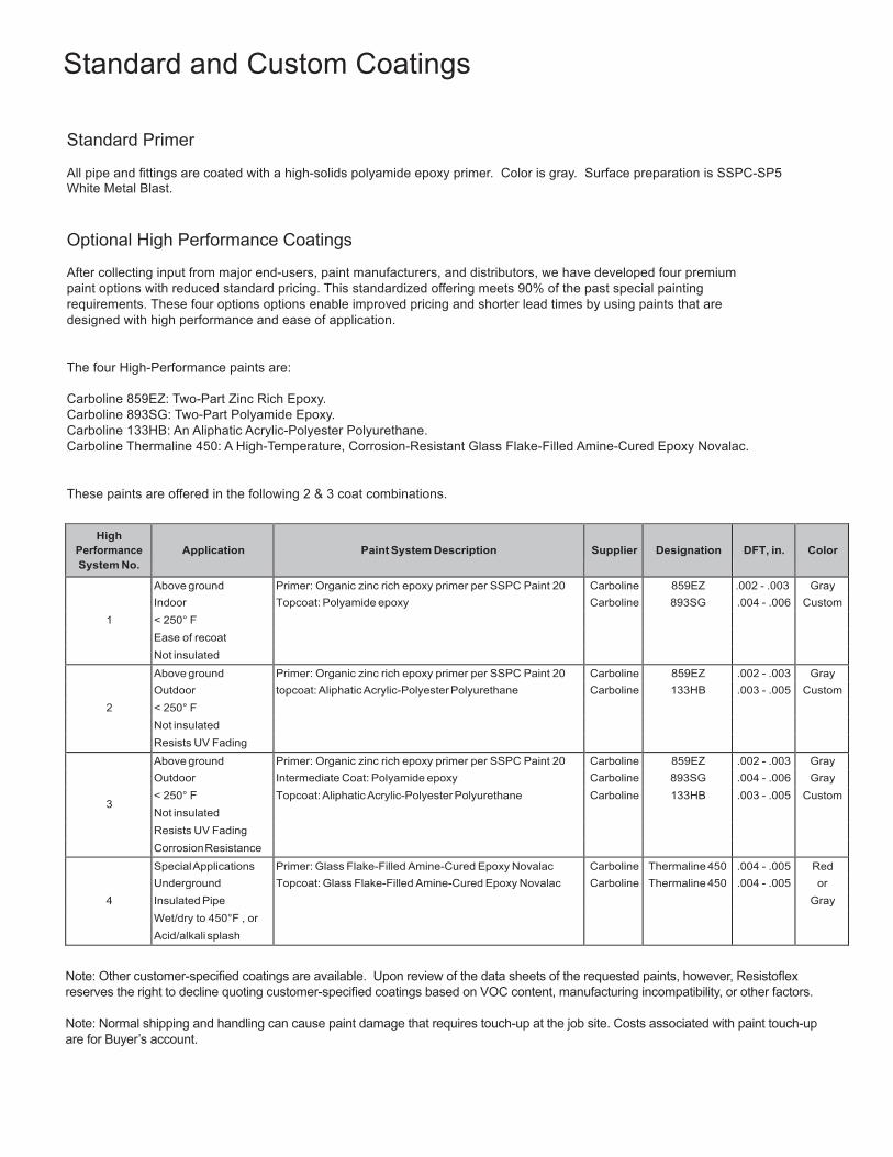
Standard and Custom Coatings
Standard Primer
All pipe and fittings are coated with a high-solids polyamide epoxy primer. Color is gray. Surface preparation is SSPC-SP5 White Metal Blast.
Optional High Performance Coatings
After collecting input from major end-users, paint manufacturers, and distributors, we have developed four premium paint options with reduced standard pricing. This standardized offering meets 90% of the past special painting requirements. These four options options enable improved pricing and shorter lead times by using paints that are designed with high performance and ease of application.
The four High-Performance paints are:
Carboline 859EZ: Two-Part Zinc Rich Epoxy. Carboline 893SG: Two-Part Polyamide Epoxy. Carboline 133HB: An Aliphatic Acrylic-Polyester Polyurethane. Carboline Thermaline 450: A High-Temperature, Corrosion-Resistant Glass Flake-Filled Amine-Cured Epoxy Novalac.
These paints are offered in the following 2 & 3 coat combinations.
High
Performance System No.
Application
Paint System Description
Supplier
Designation
DFT, in.
Color
1
Above ground Primer: Organic zinc rich epoxy primer per SSPC Paint 20 Carboline 859EZ .002 - .003 Gray Indoor Topcoat: Polyamide epoxy Carboline 893SG .004 - .006 Custom < 250° F Ease of recoat Not insulated
2
Above ground Primer: Organic zinc rich epoxy primer per SSPC Paint 20 Carboline 859EZ .002 - .003 Gray Outdoor topcoat: Aliphatic Acrylic-Polyester Polyurethane Carboline 133HB .003 - .005 Custom < 250° F Not insulated Resists UV Fading
3
Above ground Primer: Organic zinc rich epoxy primer per SSPC Paint 20 Carboline 859EZ .002 - .003 Gray Outdoor Intermediate Coat: Polyamide epoxy Carboline 893SG .004 - .006 Gray < 250° F Not insulated
Topcoat: Aliphatic Acrylic-Polyester Polyurethane Carboline 133HB .003 - .005 Custom
Resists UV Fading Corrosion Resistance
4
Special Applications Primer: Glass Flake-Filled Amine-Cured Epoxy Novalac Carboline Thermaline 450 .004 - .005 Red Underground Topcoat: Glass Flake-Filled Amine-Cured Epoxy Novalac Carboline Thermaline 450 .004 - .005 or Insulated Pipe Gray Wet/dry to 450°F , or Acid/alkali splash
Note: Other customer-specified coatings are available. Upon review of the data sheets of the requested paints, however, Resistoflex reserves the right to decline quoting customer-specified coatings based on VOC content, manufacturing incompatibility, or other factors.
Note: Normal shipping and handling can cause paint damage that requires touch-up at the job site. Costs associated with paint touch-up are for Buyer’s account.
10
Liner Characteristics
PTFE
PFA
PP PVDF
(homopolymer) PVDF
(copolymer)
ETFE
Service Temperature Range, °F1 -20°F to 450°F 0°F to 450°F 0°F to 225°F 0°F to 275°F -20°F to 275°F -20°F to 300°F
Liner Color White Natural Orange3 Black3 Black3 Natural Color of Liner Identification Band White with
Black Lettering2
Brown w/ White Lettering
Orange w/ Black Lettering
Black w/ White Lettering
Black w/ White Lettering
Gray w/ White Lettering
Coefficient of Thermal Expansion of Pipe Liner Prior to Lining, in./in./°F
-5
-5
-5
-5
-5
-5
Thermal Conductivity ("K" Factor) of Liner, BTU-in./hr.-sq. ft.-°F
1.7
1.3
0.8
0.9
1.18
1.65
Tensile Strength of Liner at Yield, psi 3,000 - 4,000 3,800 - 4,500 4,000 - 4,500 5,000 - 6,000 4,500 - 5,500 6700
Elongation of Liner at Yield, % 250 - 350 300 - 350 10 - 13 8 - 10 10 - 20 150 - 300
Compressive Strength of Liner at Yield, psi 1,700 3,500 5,500 - 8,000 10,000 - 16,000 5000 - 8500 2,500
Specific Gravity of Liner 2.14 - 2.19 2.12 - 2.17 0.90 - 0.92 1.75 - 1.78 1.76 - 1.78 1.70 - 1.72
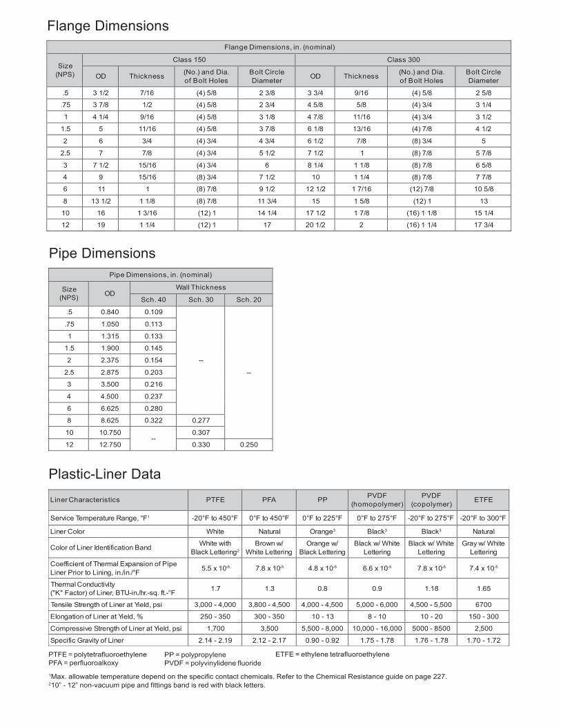
Flange Dimensions
Flange Dimensions, in. (nominal)
Size (NPS)
Class 150 Class 300
OD
Thickness (No.) and Dia. of Bolt Holes
Bolt Circle Diameter
OD
Thickness (No.) and Dia.
of Bolt Holes Bolt Circle Diameter
.5 3 1/2 7/16 (4) 5/8 2 3/8 3 3/4 9/16 (4) 5/8 2 5/8
.75 3 7/8 1/2 (4) 5/8 2 3/4 4 5/8 5/8 (4) 3/4 3 1/4
1 4 1/4 9/16 (4) 5/8 3 1/8 4 7/8 11/16 (4) 3/4 3 1/2
1.5 5 11/16 (4) 5/8 3 7/8 6 1/8 13/16 (4) 7/8 4 1/2
2 6 3/4 (4) 3/4 4 3/4 6 1/2 7/8 (8) 3/4 5
2.5 7 7/8 (4) 3/4 5 1/2 7 1/2 1 (8) 7/8 5 7/8
3 7 1/2 15/16 (4) 3/4 6 8 1/4 1 1/8 (8) 7/8 6 5/8
4 9 15/16 (8) 3/4 7 1/2 10 1 1/4 (8) 7/8 7 7/8
6 11 1 (8) 7/8 9 1/2 12 1/2 1 7/16 (12) 7/8 10 5/8
8 13 1/2 1 1/8 (8) 7/8 11 3/4 15 1 5/8 (12) 1 13
10 16 1 3/16 (12) 1 14 1/4 17 1/2 1 7/8 (16) 1 1/8 15 1/4
12 19 1 1/4 (12) 1 17 20 1/2 2 (16) 1 1/4 17 3/4
Pipe Dimensions
Pipe Dimensions, in. (nominal)
Size (NPS)
OD
Wall Thickness
Sch. 40 Sch. 30 Sch. 20
.5 0.840 0.109
--
--
.75 1.050 0.113
1 1.315 0.133
1.5 1.900 0.145
2 2.375 0.154
2.5 2.875 0.203
3 3.500 0.216
4 4.500 0.237
6 6.625 0.280
8 8.625 0.322 0.277
10 10.750 --
0.307
12 12.750 0.330 0.250
Plastic-Liner Data
5.5 x 10 7.8 x 10 4.8 x 10 6.6 x 10 7.8 x 10 7.4 x 10
PTFE = polytetrafluoroethylene PFA = perfluoroalkoxy
PP = polypropylene PVDF = polyvinylidene fluoride
ETFE = ethylene tetrafluoroethylene
1Max. allowable temperature depend on the specific contact chemicals. Refer to the Chemical Resistance guide on page 227. 210” - 12” non-vacuum pipe and fittings band is red with black letters. 3Available unpigmented as a special option.
11
700
600
500
6
7
400
300
0 0 50 100 150 200 250 300 350 400 450
-18 10 38 65 93 121 149 177 204 232
Pres
sure
(psi
g)
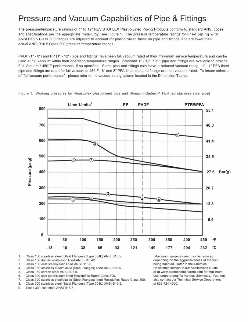
Pressure and Vacuum Capabilities of Pipe & Fittings
The pressure/temperature ratings of 1" to 12" RESISTOFLEX Plastic-Lined Piping Products conform to standard ANSI codes and specifications per the appropriate metallurgy. See Figure 1. The pressure/temperature ratings for l ined piping with ANSI B16.5 Class 300 flanges are adjusted to account for plastic raised faces on pipe and fittings, and are lower than actual ANSI B16.5 Class 300 pressure/temperature ratings.
PVDF (1" - 8") and PP (1" - 12") pipe and fittings have been full vacuum rated at their maximum service temperature and can be used at full vacuum within their operating temperature ranges. Standard 1" - 12" PTFE pipe and fittings are available to provide Full Vacuum / 450°F performance, if so specified. Some pipe and fittings may have a reduced vacuum rating. 1" - 4" PFA-lined pipe and fittings are rated for full vacuum to 450 F. 6" and 8" PFA-lined pipe and fittings are non-vacuum rated. To insure selection of “full vacuum performance” - please refer to the vacuum rating column located in the Dimension Tables.
Figure 1: Working pressures for Resistoflex plastic-lined pipe and fittings (includes PTFE-lined stainless steel pipe)
800
Liner Limits* PP PVDF PTFE/PFA 55.1
48.3
9
8 41.4
34.5
27.6 Bar(g)
3
1 2 4 5 200
100
20.7
13.8
6.9
oF oC
1. Class 150 stainless steel (Steel Flanges) (Type 304L) ANSI B16.5. 2. Class 150 ductile iron/plastic lined ANSI B16.42. 3. Class 150 cast steel/plastic lined ANSI B16.5. 4. Class 150 stainless steel/plastic (Steel Flanges) lined ANSI B16.5. 5. Class 150 carbon steel ANSI B16.5. 6. Class 300 cast steel/plastic lined Resistoflex Rated Class 300. 7. Class 300 stainless steel/plastic (Steel Flanges) lined Resistoflex Rated Class 300. 8. Class 300 stainless steel (Steel Flanges) (Type 304L) ANSI B16.5. 9. Class 300 cast steel ANSI B16.5.
Maximum temperatures may be reduced depending on the aggressiveness of the fluid being handled. Refer to the Chemical Resistance section in our Applications Guide or at www.cranechempharma.com for maximum use temperatures for various chemicals. You may also contact our Technical Service Department at 828-724-4000.
12
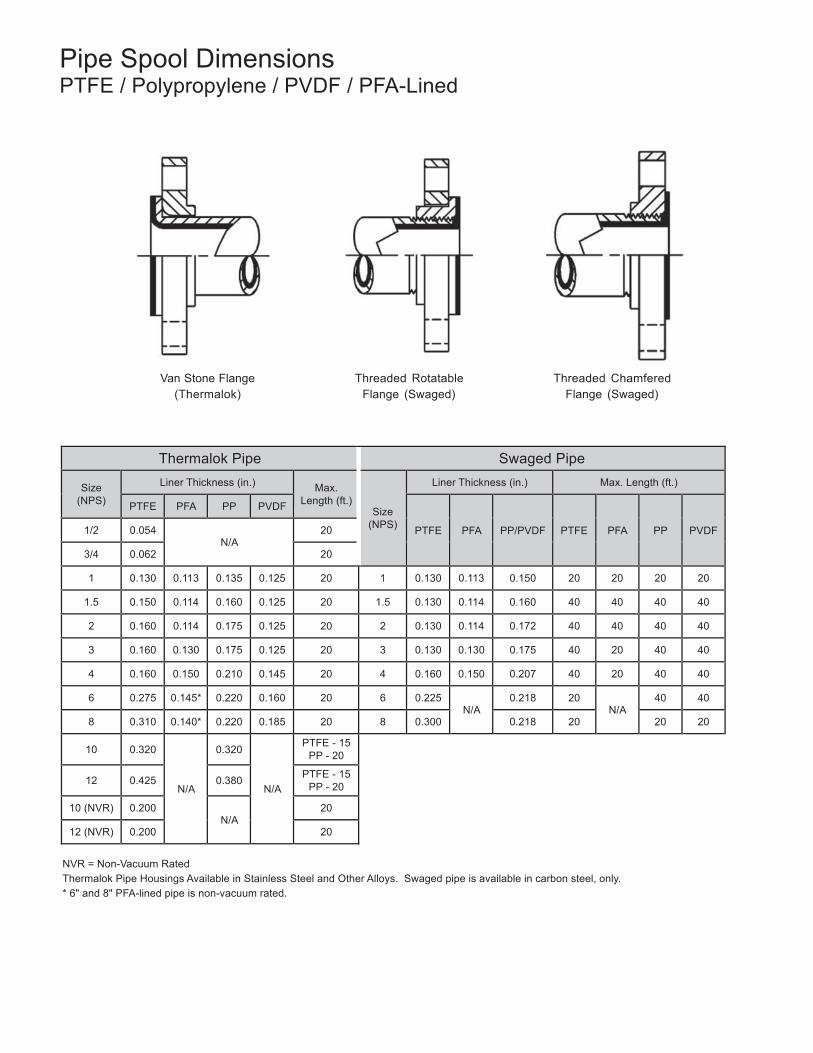
Pipe Spool Dimensions PTFE / Polypropylene / PVDF / PFA-Lined
Van Stone Flange
(Thermalok) Threaded Rotatable
Flange (Swaged) Threaded Chamfered
Flange (Swaged)
Thermalok Pipe Swaged Pipe
Size (NPS)
Liner Thickness (in.) Max.
Length (ft.)
Size (NPS)
Liner Thickness (in.) Max. Length (ft.)
PTFE PFA PP PVDF
PTFE
PFA
PP/PVDF
PTFE
PFA
PP
PVDF 1/2 0.054 N/A
20
3/4 0.062 20
1 0.130 0.113 0.135 0.125 20 1 0.130 0.113 0.150 20 20 20 20
1.5 0.150 0.114 0.160 0.125 20 1.5 0.130 0.114 0.160 40 40 40 40
2 0.160 0.114 0.175 0.125 20 2 0.130 0.114 0.172 40 40 40 40
3 0.160 0.130 0.175 0.125 20 3 0.130 0.130 0.175 40 20 40 40
4 0.160 0.150 0.210 0.145 20 4 0.160 0.150 0.207 40 20 40 40
6 0.275 0.145* 0.220 0.160 20 6 0.225 N/A
0.218 20 N/A
40 40
8 0.310 0.140* 0.220 0.185 20 8 0.300 0.218 20 20 20
10
0.320
N/A
0.320
N/A
PTFE - 15 PP - 20
12
0.425
0.380 PTFE - 15
PP - 20
10 (NVR) 0.200 N/A
20
12 (NVR) 0.200 20
NVR = Non-Vacuum Rated Thermalok Pipe Housings Available in Stainless Steel and Other Alloys. Swaged pipe is available in carbon steel, only. * 6" and 8" PFA-lined pipe is non-vacuum rated.
13
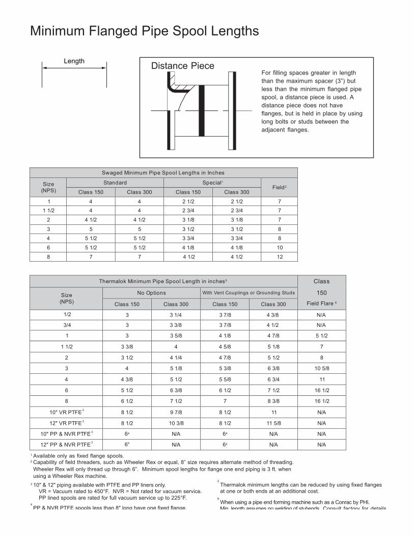
Minimum Flanged Pipe Spool Lengths
Length
Distance Piece
For filling spaces greater in length than the maximum spacer (3”) but less than the minimum flanged pipe spool, a distance piece is used. A distance piece does not have flanges, but is held in place by using long bolts or studs between the adjacent flanges.
Sw aged Minimum Pipe Spool Lengths in Inches
Size (NPS)
Standard Special1 Field2
Class 150 Class 300 Class 150 Class 300
1 4 4 2 1/2 2 1/2 7
1 1/2 4 4 2 3/4 2 3/4 7
2 4 1/2 4 1/2 3 1/8 3 1/8 7
3 5 5 3 1/2 3 1/2 8
4 5 1/2 5 1/2 3 3/4 3 3/4 8
6 5 1/2 5 1/2 4 1/8 4 1/8 10
8 7 7 4 1/2 4 1/2 12
Thermalok Minimum Pipe Spool Length in inches5 Class
150
Field Flare 6
Size (NPS)
No Options With Vent Couplings or Grounding Studs
Class 150 Class 300 Class 150 Class 300
1/2 3 3 1/4 3 7/8 4 3/8 N/A
3/4 3 3 3/8 3 7/8 4 1/2 N/A
1 3 3 5/8 4 1/8 4 7/8 5 1/2
1 1/2 3 3/8 4 4 5/8 5 1/8 7
2 3 1/2 4 1/4 4 7/8 5 1/2 8
3 4 5 1/8 5 3/8 6 3/8 10 5/8
4 4 3/8 5 1/2 5 5/8 6 3/4 11
6 5 1/2 6 3/8 6 1/2 7 1/2 16 1/2
8 6 1/2 7 1/2 7 8 3/8 16 1/2
10" VR PTFE 3 8 1/2 9 7/8 8 1/2 11 N/A
12" VR PTFE 3 8 1/2 10 3/8 8 1/2 11 5/8 N/A
10" PP & NVR PTFE 3 64 N/A 64 N/A N/A
12" PP & NVR PTFE 3 64 N/A 64 N/A N/A
1 Available only as fixed flange spools. 2 Capability of field threaders, such as Wheeler Rex or equal, 8” size requires alternate method of threading. Wheeler Rex will only thread up through 6”. Minimum spool lengths for flange one end piping is 3 ft. when using a Wheeler Rex machine.
3 10" & 12" piping available with PTFE and PP liners only. VR = Vacuum rated to 450°F. NVR = Not rated for vacuum service. PP lined spools are rated for full vacuum service up to 225°F.
4 PP & NVR PTFE spools less than 8" long have one fixed flange.
5 Thermalok minimum lengths can be reduced by using fixed flanges at one or both ends at an additional cost.
6 When using a pipe end forming machine such as a Conrac by PHI. Min. length assumes no welding of stubends. Consult factory for details.
14
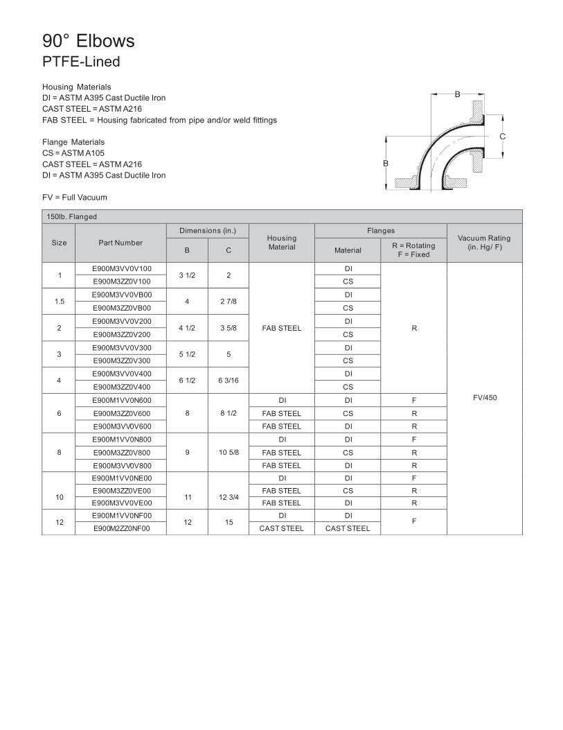
150lb. Flanged
Size
Part Number
Dimensions (in.) Housing Material
Flanges Vacuum Rating
(in. Hg/ F)
B
C
Material R = Rotating F = Fixed
1
E900M3VV0V100 3 1/2
2
FAB STEEL
DI
R
FV/450
E900M3ZZ0V100 CS
1.5 E900M3VV0VB00
4
2 7/8 DI
E900M3ZZ0VB00 CS
2 E900M3VV0V200
4 1/2
3 5/8 DI
E900M3ZZ0V200 CS
3 E900M3VV0V300
5 1/2
5 DI
E900M3ZZ0V300 CS
4 E900M3VV0V400
6 1/2
6 3/16 DI
E900M3ZZ0V400 CS
6
E900M1VV0N600
8
8 1/2
DI DI F
E900M3ZZ0V600 FAB STEEL CS R
E900M3VV0V600 FAB STEEL DI R
8
E900M1VV0N800
9
10 5/8
DI DI F
E900M3ZZ0V800 FAB STEEL CS R
E900M3VV0V800 FAB STEEL DI R
10
E900M1VV0NE00
11
12 3/4
DI DI F
E900M3ZZ0VE00 FAB STEEL CS R
E900M3VV0VE00 FAB STEEL DI R
12 E900M1VV0NF00
12
15 DI DI
F E900M2ZZ0NF00 CAST STEEL CAST STEEL
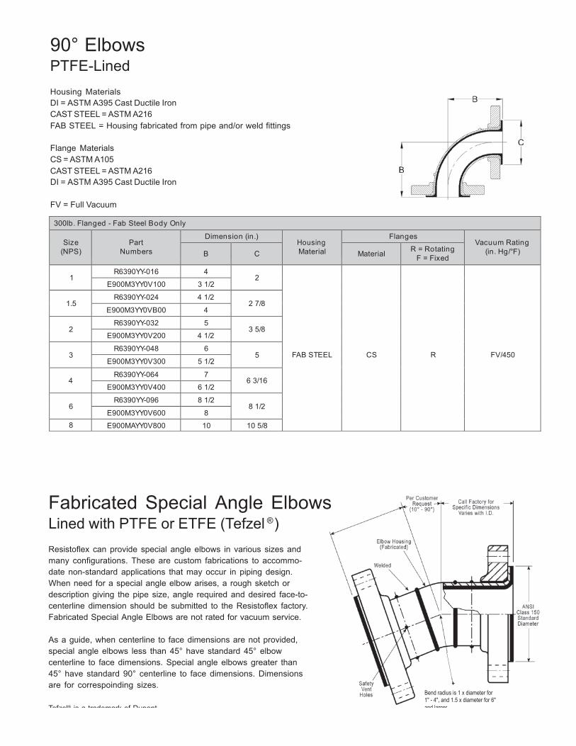
90° Elbows PTFE-Lined
Housing Materials DI = ASTM A395 Cast Ductile Iron CAST STEEL = ASTM A216 FAB STEEL = Housing fabricated from pipe and/or weld fittings
Flange Materials CS = ASTM A105 CAST STEEL = ASTM A216 DI = ASTM A395 Cast Ductile Iron
FV = Full Vacuum
15
300lb. Flanged - Fab Steel Body Only
Size (NPS)
Part
Numbers
Dimension (in.) Housing Material
Flanges Vacuum Rating
(in. Hg/°F)
B
C
Material R = Rotating F = Fixed
1
R6390YY-016 4 2
FAB STEEL
CS
R
FV/450
E900M3YY0V100 3 1/2
1.5 R6390YY-024 4 1/2
2 7/8 E900M3YY0VB00 4
2
R6390YY-032 5 3 5/8
E900M3YY0V200 4 1/2
3 R6390YY-048 6
5 E900M3YY0V300 5 1/2
4
R6390YY-064 7 6 3/16
E900M3YY0V400 6 1/2
6 R6390YY-096 8 1/2
8 1/2 E900M3YY0V600 8
8 E900MAYY0V800 10 10 5/8
90° Elbows PTFE-Lined
Housing Materials DI = ASTM A395 Cast Ductile Iron CAST STEEL = ASTM A216 FAB STEEL = Housing fabricated from pipe and/or weld fittings
Flange Materials CS = ASTM A105 CAST STEEL = ASTM A216 DI = ASTM A395 Cast Ductile Iron
FV = Full Vacuum
Fabricated Special Angle Elbows Lined with PTFE or ETFE (Tefzel ® )
Resistoflex can provide special angle elbows in various sizes and many configurations. These are custom fabrications to accommo- date non-standard applications that may occur in piping design. When need for a special angle elbow arises, a rough sketch or description giving the pipe size, angle required and desired face-to- centerline dimension should be submitted to the Resistoflex factory. Fabricated Special Angle Elbows are not rated for vacuum service.
As a guide, when centerline to face dimensions are not provided, special angle elbows less than 45° have standard 45° elbow centerline to face dimensions. Special angle elbows greater than 45° have standard 90° centerline to face dimensions. Dimensions are for correspoinding sizes.
Tefzel® is a trademark of Dupont.
Bend radius is 1 x diameter for 1" - 4", and 1.5 x diameter for 6" and larger.
16
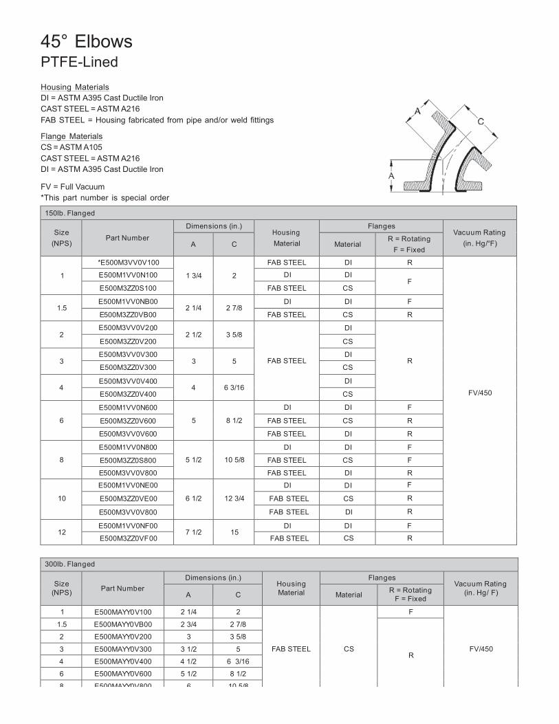
45° Elbows PTFE-Lined
Housing Materials DI = ASTM A395 Cast Ductile Iron CAST STEEL = ASTM A216 FAB STEEL = Housing fabricated from pipe and/or weld fittings
Flange Materials CS = ASTM A105 CAST STEEL = ASTM A216 DI = ASTM A395 Cast Ductile Iron
FV = Full Vacuum *This part number is special order
150lb. Flanged
Size (NPS)
Part Number
Dimensions (in.) Housing Material
Flanges Vacuum Rating
(in. Hg/°F)
A
C
Material R = Rotating
F = Fixed
1
*E500M3VV0V100
1 3/4
2
FAB STEEL DI R
FV/450
E500M1VV0N100 DI DI F
E500M3ZZ0S100 FAB STEEL CS
1.5 E500M1VV0NB00
2 1/4
2 7/8 DI DI F
E500M3ZZ0VB00 FAB STEEL CS R
2 E500M3VV0V200
2 1/2
3 5/8
FAB STEEL
DI
R
E500M3ZZ0V200 CS
3 E500M3VV0V300
3
5 DI
E500M3ZZ0V300 CS
4 E500M3VV0V400
4
6 3/16 DI
E500M3ZZ0V400 CS
6
E500M1VV0N600
5
8 1/2
DI DI F
E500M3ZZ0V600 FAB STEEL CS R
E500M3VV0V600 FAB STEEL DI R
8
E500M1VV0N800
5 1/2
10 5/8
DI DI F
E500M3ZZ0S800 FAB STEEL CS F
E500M3VV0V800 FAB STEEL DI R
10
E500M1VV0NE00
6 1/2
12 3/4
DI DI F
E500M3ZZ0VE00 FAB STEEL CS R
E500M3VV0V800 FAB STEEL DI R
12
E500M1VV0NF00 7 1/2
15
DI DI F
E500M3ZZ0VF00 FAB STEEL CS R
300lb. Flanged
Size
(NPS)
Part Number
Dimensions (in.) Housing Material
Flanges Vacuum Rating
(in. Hg/ F)
A
C
Material R = Rotating F = Fixed
1 E500MAYY0V100 2 1/4 2
FAB STEEL
CS
F
FV/450
1.5 E500MAYY0VB00 2 3/4 2 7/8
R
2 E500MAYY0V200 3 3 5/8
3 E500MAYY0V300 3 1/2 5
4 E500MAYY0V400 4 1/2 6 3/16
6 E500MAYY0V600 5 1/2 8 1/2
8 E500MAYY0V800 6 10 5/8
17
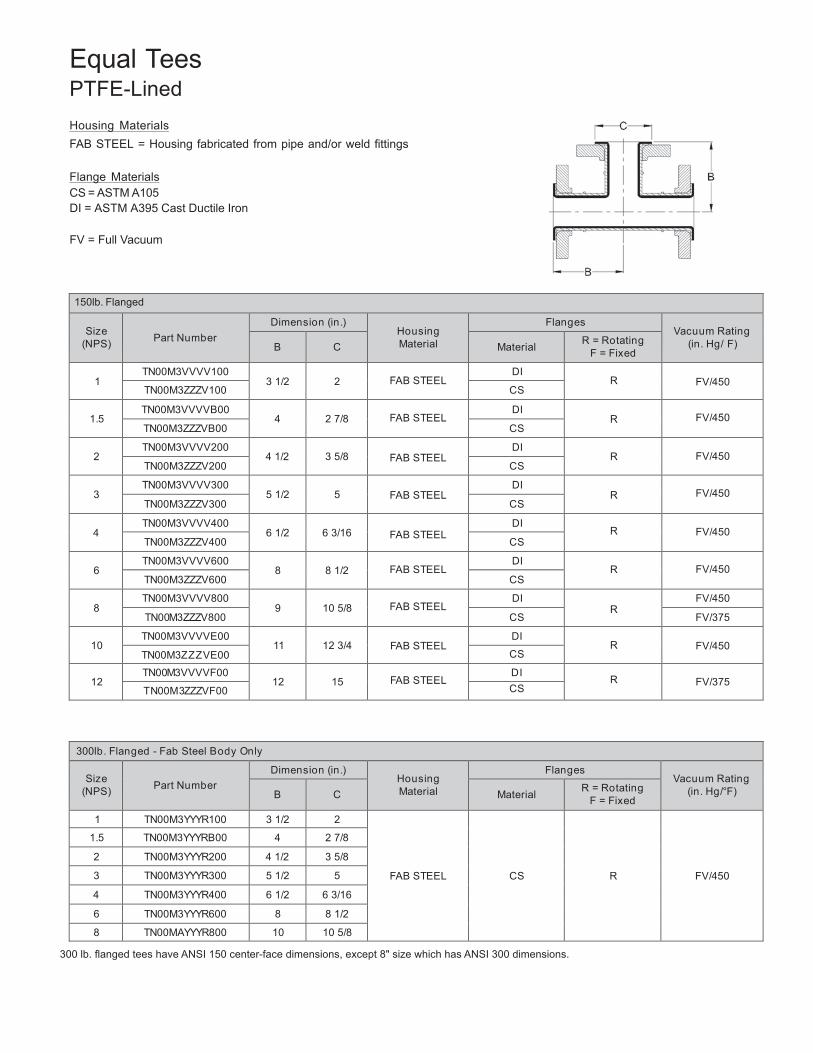
Equal Tees PTFE-Lined
Housing Materials FAB STEEL = Housing fabricated from pipe and/or weld fittings
Flange Materials CS = ASTM A105 DI = ASTM A395 Cast Ductile Iron
FV = Full Vacuum
150lb. Flanged
Size (NPS)
Part Number
Dimension (in.) Housing Material
Flanges Vacuum Rating
(in. Hg/ F)
B
C
Material R = Rotating F = Fixed
1
TN00M3VVVV100 3 1/2
2
FAB STEEL
DI R
FV/450
TN00M3ZZZV100 CS
1.5 TN00M3VVVVB00
4
2 7/8
FAB STEEL DI
R
FV/450 TN00M3ZZZVB00 CS
2
TN00M3VVVV200 4 1/2
3 5/8
FAB STEEL
DI R
FV/450
TN00M3ZZZV200 CS
3 TN00M3VVVV300
5 1/2
5
FAB STEEL DI
R
FV/450 TN00M3ZZZV300 CS
4
TN00M3VVVV400 6 1/2
6 3/16
FAB STEEL
DI R
FV/450
TN00M3ZZZV400 CS
6 TN00M3VVVV600
8
8 1/2
FAB STEEL DI
R
FV/450 TN00M3ZZZV600 CS
8
TN00M3VVVV800 9
10 5/8
FAB STEEL
DI R
FV/450
TN00M3ZZZV800 CS FV/375
10 TN00M3VVVVE00
11
12 3/4
FAB STEEL DI
R
FV/450 TN00M3ZZZVE00 CS
12
TN00M3VVVVF00 12
15
FAB STEEL
DI R
FV/375
TN00M3ZZZVF00 CS
300lb. Flanged - Fab Steel Body Only
Size (NPS)
Part Number
Dimension (in.) Housing Material
Flanges Vacuum Rating
(in. Hg/°F)
B
C
Material R = Rotating F = Fixed
1 TN00M3YYYR100 3 1/2 2
FAB STEEL
CS
R
FV/450
1.5 TN00M3YYYRB00 4 2 7/8
2 TN00M3YYYR200 4 1/2 3 5/8
3 TN00M3YYYR300 5 1/2 5
4 TN00M3YYYR400 6 1/2 6 3/16
6 TN00M3YYYR600 8 8 1/2
8 TN00MAYYYR800 10 10 5/8
300 lb. flanged tees have ANSI 150 center-face dimensions, except 8" size which has ANSI 300 dimensions.
18
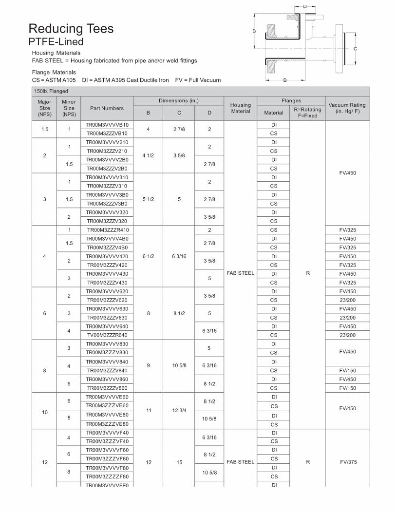
Reducing Tees PTFE-Lined
Housing Materials FAB STEEL = Housing fabricated from pipe and/or weld fittings
Flange Materials CS = ASTM A105 DI = ASTM A395 Cast Ductile Iron FV = Full Vacuum
150lb. Flanged
Major Size
(NPS)
Minor Size
(NPS)
Part Numbers
Dimensions (in.) Housing Material
Flanges Vacuum Rating
(in. Hg/ F)
B
C
D
Material R=Rotating F=Fixed
1.5
1
TR00M3VVVVB10 4
2 7/8
2
FAB STEEL
DI
R
FV/450
TR00M3ZZZVB10 CS
2
1
TR00M3VVVV210
4 1/2
3 5/8
2
DI
TR00M3ZZZV210 CS
1.5 TR00M3VVVV2B0
2 7/8 DI
TR00M3ZZZV2B0 CS
3
1
TR00M3VVVV310
5 1/2
5
2
DI
TR00M3ZZZV310 CS
1.5 TR00M3VVVV3B0
2 7/8 DI
TR00M3ZZZV3B0 CS
2 TR00M3VVVV320
3 5/8 DI
TR00M3ZZZV320 CS
4
1 TR00M3ZZZR410
6 1/2
6 3/16
2 CS FV/325
1.5 TR00M3VVVV4B0
2 7/8 DI FV/450
TR00M3ZZZV4B0 CS FV/325
2 TR00M3VVVV420
3 5/8 DI FV/450
TR00M3ZZZV420 CS FV/325
3 TR00M3VVVV430
5 DI FV/450
TR00M3ZZZV430 CS FV/325
6
2
TR00M3VVVV620
8
8 1/2
3 5/8
DI FV/450
TR00M3ZZZV620 CS 23/200
3 TR00M3VVVV630
5 DI FV/450
TR00M3ZZZV630 CS 23/200
4 TR00M3VVVV640
6 3/16 DI FV/450
TV00M3ZZZR640 CS 23/200
8
3
TR00M3VVVV830
9
10 5/8
5
DI FV/450 TR00M3ZZZV830 CS
4
TR00M3VVVV840 6 3/16
DI
TR00M3ZZZV840 CS FV/150
6 TR00M3VVVV860
8 1/2 DI FV/450
TR00M3ZZZV860 CS FV/150
10
6
TR00M3VVVVE60
11
12 3/4
8 1/2
DI
FV/450 TR00M3ZZZVE60 CS
8 TR00M3VVVVE80 10 5/8 DI
TR00M3ZZZVE80 CS
12
4
TR00M3VVVVF40
12
15
6 3/16
FAB STEEL
DI
R
FV/375
TR00M3ZZZVF40 CS
6 TR00M3VVVVF60
8 1/2 DI
TR00M3ZZZVF60 CS
8 TR00M3VVVVF80
10 5/8 DI
TR00M3ZZZZF80 CS TR00M3VVVVFE0 DI

19
10 TR00M3ZZZVFE0 12 3/4 CS
20
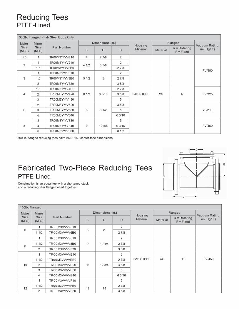
Reducing Tees PTFE-Lined
300lb. Flanged - Fab Steel Body Only
Major Size
(NPS)
Minor Size
(NPS)
Part Number
Dimensions (in.) Housing Material
Flanges Vacuum Rating
(in. Hg/ F)
B
C
D
Material R = Rotating F = Fixed
1.5 1 TR00M3YYYVB10 4 2 7/8 2
FAB STEEL
CS
R
FV/450
2
1 TR00M3YYYV210 4 1/2
3 5/8
2
1.5 TR00M3YYYV2B0 2 7/8
3
1 TR00M3YYYV310
5 1/2
5
2
1.5 TR00M3YYYV3B0 2 7/8
2 TR00M3YYYV320 3 5/8
4
1.5 TR00M3YYYV4B0
6 1/2
6 3/16
2 7/8
FV/325 2 TR00M3YYYV420 3 5/8
3 TR00M3YYYV430 5
6
2 TR00M3YYYV620
8
8 1/2
3 5/8
23/200 3 TR00M3YYYV630 5
4 TR00M3YYYV640 6 3/16
8
3 TR00M3YYYV830
9
10 5/8
5
FV/450 4 TR00M3YYYV840 6 3/16
6 TR00M3YYYV860 8 1/2
300 lb. flanged reducing tees have ANSI 150 center-face dimensions.
Fabricated Two-Piece Reducing Tees PTFE-Lined Construction is an equal tee with a shortened stack and a reducing filler flange bolted together
150lb. Flanged
Major Size
(NPS)
Minor Size
(NPS)
Part Number
Dimensions (in.) Housing Material
Flanges Vacuum Rating
(in. Hg/ F)
B
C
D
Material R = Rotating F = Fixed
6
1 TR 00 M3VVVV610 8
8
2
FAB STEEL
CS
R
FV/450
1 1/2 TR 00 M3VVVV6B0 2 7/8
8
1 TR 00 M3VVVV810
9
10 1/4
2
1 1/2 TR 00 M3VVVV8B0 2 7/8
2 TR 00 M3VVVV820 3 5/8
10
1 TR 00 M3VVVVE10
11
12 3/4
2
1 1/2 TR 00 M3VVVVEB0 2 7/8
2 TR 00 M3VVVVE20 3 5/8
3 TR 00 M3VVVVE30 5
4 TR 00 M3VVVVE40 6 3/16
12
1 TR 00 M3VVVVF10
12
15
2
1 1/2 TR 00 M3VVVVFB0 2 7/8
2 TR 00 M3VVVVF20 3 5/8

21
3 TR 00 M3VVVVF30 5
22
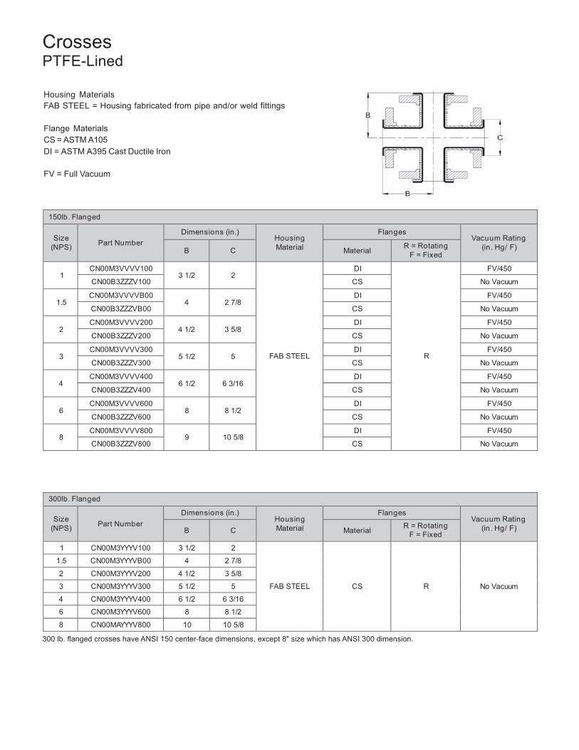
Crosses PTFE-Lined
Housing Materials FAB STEEL = Housing fabricated from pipe and/or weld fittings
Flange Materials CS = ASTM A105 DI = ASTM A395 Cast Ductile Iron
FV = Full Vacuum
150lb. Flanged
Size
(NPS)
Part Number
Dimensions (in.) Housing Material
Flanges Vacuum Rating
(in. Hg/ F)
B
C
Material R = Rotating F = Fixed
1
CN00M3VVVV100 3 1/2
2
FAB STEEL
DI
R
FV/450
CN00B3ZZZV100 CS No Vacuum
1.5 CN00M3VVVVB00
4
2 7/8 DI FV/450
CN00B3ZZZVB00 CS No Vacuum
2 CN00M3VVVV200
4 1/2
3 5/8 DI FV/450
CN00B3ZZZV200 CS No Vacuum
3 CN00M3VVVV300
5 1/2
5 DI FV/450
CN00B3ZZZV300 CS No Vacuum
4 CN00M3VVVV400
6 1/2
6 3/16 DI FV/450
CN00B3ZZZV400 CS No Vacuum
6 CN00M3VVVV600
8
8 1/2 DI FV/450
CN00B3ZZZV600 CS No Vacuum
8 CN00M3VVVV800
9
10 5/8 DI FV/450
CN00B3ZZZV800 CS No Vacuum
300lb. Flanged
Size (NPS)
Part Number
Dimensions (in.) Housing Material
Flanges Vacuum Rating
(in. Hg/ F)
B
C
Material R = Rotating F = Fixed
1 CN00M3YYYV100 3 1/2 2
FAB STEEL
CS
R
No Vacuum
1.5 CN00M3YYYVB00 4 2 7/8
2 CN00M3YYYV200 4 1/2 3 5/8
3 CN00M3YYYV300 5 1/2 5
4 CN00M3YYYV400 6 1/2 6 3/16
6 CN00M3YYYV600 8 8 1/2
8 CN00MAYYYV800 10 10 5/8
300 lb. flanged crosses have ANSI 150 center-face dimensions, except 8" size which has ANSI 300 dimension.
23
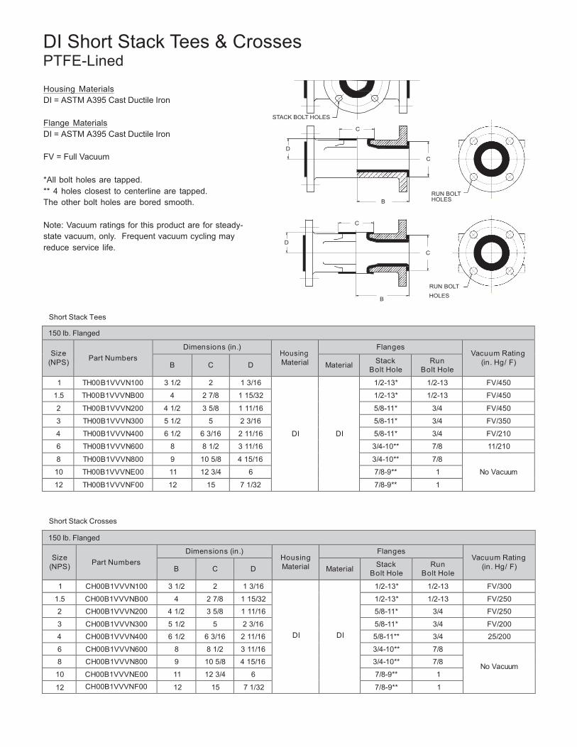
DI Short Stack Tees & Crosses PTFE-Lined
Housing Materials DI = ASTM A395 Cast Ductile Iron
Flange Materials DI = ASTM A395 Cast Ductile Iron
FV = Full Vacuum
*All bolt holes are tapped. ** 4 holes closest to centerline are tapped. The other bolt holes are bored smooth.
Note: Vacuum ratings for this product are for steady- state vacuum, only. Frequent vacuum cycling may reduce service life.
STACK BOLT HOLES
C
D
B
C
D
C
RUN BOLT HOLES
C
RUN BOLT
B HOLES
Short Stack Tees
150 lb. Flanged
Size (NPS)
Part Numbers
Dimensions (in.) Housing Material
Flanges Vacuum Rating
(in. Hg/ F)
B
C
D
Material Stack Bolt Hole
Run Bolt Hole
1 TH00 B1VVVN100 3 1/2 2 1 3/16
DI
DI
1/2-13* 1/2-13 FV/450
1.5 TH00 B1VVVNB00 4 2 7/8 1 15/32 1/2-13* 1/2-13 FV/450
2 TH00 B1VVVN200 4 1/2 3 5/8 1 11/16 5/8-11* 3/4 FV/450
3 TH00B1VVVN300 5 1/2 5 2 3/16 5/8-11* 3/4 FV/350
4 TH00B1VVVN400 6 1/2 6 3/16 2 11/16 5/8-11* 3/4 FV/210
6 TH00B1VVVN600 8 8 1/2 3 11/16 3/4-10** 7/8 11/210
8 TH00B1VVVN800 9 10 5/8 4 15/16 3/4-10** 7/8
No Vacuum 10 TH00B1VVVNE00 11 12 3/4 6 7/8-9** 1
12 TH00B1VVVNF00 12 15 7 1/32 7/8-9** 1
Short Stack Crosses
150 lb. Flanged
Size (NPS)
Part Numbers
Dimensions (in.) Housing Material
Flanges Vacuum Rating
(in. Hg/ F)
B
C
D
Material Stack Bolt Hole
Run Bolt Hole
1 CH00B1VVVN100 3 1/2 2 1 3/16
DI
DI
1/2-13* 1/2-13 FV/300
1.5 CH00B1VVVNB00 4 2 7/8 1 15/32 1/2-13* 1/2-13 FV/250
2 CH00B1VVVN200 4 1/2 3 5/8 1 11/16 5/8-11* 3/4 FV/250
3 CH00B1VVVN300 5 1/2 5 2 3/16 5/8-11* 3/4 FV/200
4 CH00B1VVVN400 6 1/2 6 3/16 2 11/16 5/8-11** 3/4 25/200
6 CH00B1VVVN600 8 8 1/2 3 11/16 3/4-10** 7/8
No Vacuum 8 CH00B1VVVN800 9 10 5/8 4 15/16 3/4-10** 7/8
10 CH00B1VVVNE00 11 12 3/4 6 7/8-9** 1
12 CH00B1VVVNF00 12 15 7 1/32 7/8-9** 1
24
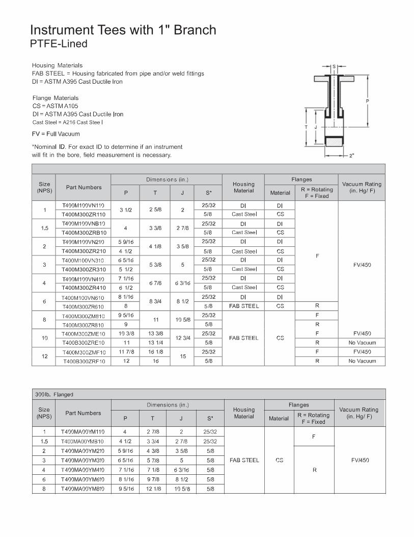
Instrument Tees with 1" Branch PTFE-Lined
T400M300ZR110
T400M300ZRB10
T400M300ZR210
T400M300ZR310
T400M300ZR410
25
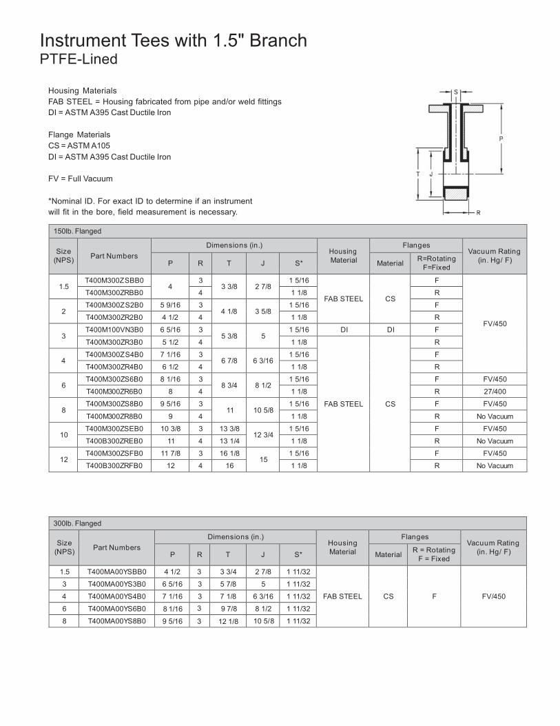
Instrument Tees with 1.5" Branch PTFE-Lined
Housing Materials FAB STEEL = Housing fabricated from pipe and/or weld fittings DI = ASTM A395 Cast Ductile Iron
Flange Materials CS = ASTM A105 DI = ASTM A395 Cast Ductile Iron
FV = Full Vacuum
*Nominal ID. For exact ID to determine if an instrument will fit in the bore, field measurement is necessary.
150lb. Flanged
Size (NPS)
Part Numbers
Dimensions (in.) Housing Material
Flanges Vacuum Rating
(in. Hg/ F)
P
R
T
J
S*
Material R=Rotating F=Fixed
1.5
T400M300ZSBB0 4
3 3 3/8
2 7/8
1 5/16
FAB STEEL
CS
F
FV/450
T400M300ZRBB0 4 1 1/8 R
2 T400M300ZS2B0 5 9/16 3
4 1/8
3 5/8 1 5/16 F
T400M300ZR2B0 4 1/2 4 1 1/8 R
3 T400M100VN3B0 6 5/16 3
5 3/8
5 1 5/16 DI DI F
T400M300ZR3B0 5 1/2 4 1 1/8
FAB STEEL
CS
R
4 T400M300ZS4B0 7 1/16 3
6 7/8
6 3/16 1 5/16 F
T400M300ZR4B0 6 1/2 4 1 1/8 R
6 T400M300ZS6B0 8 1/16 3
8 3/4
8 1/2 1 5/16 F FV/450
T400M300ZR6B0 8 4 1 1/8 R 27/400
8 T400M300ZS8B0 9 5/16 3
11
10 5/8 1 5/16 F FV/450
T400M300ZR8B0 9 4 1 1/8 R No Vacuum
10 T400M300ZSEB0 10 3/8 3 13 3/8
12 3/4 1 5/16 F FV/450
T400B300ZREB0 11 4 13 1/4 1 1/8 R No Vacuum
12 T400M300ZSFB0 11 7/8 3 16 1/8
15 1 5/16 F FV/450
T400B300ZRFB0 12 4 16 1 1/8 R No Vacuum
300lb. Flanged
Size (NPS)
Part Numbers
Dimensions (in.) Housing Material
Flanges Vacuum Rating
(in. Hg/ F)
P
R
T
J
S*
Material R = Rotating F = Fixed
1.5 T400MA00YSBB0 4 1/2 3 3 3/4 2 7/8 1 11/32
FAB STEEL
CS
F
FV/450
3 T400MA00YS3B0 6 5/16 3 5 7/8 5 1 11/32
4 T400MA00YS4B0 7 1/16 3 7 1/8 6 3/16 1 11/32
6 T400MA00YS6B0 8 1/16 3 9 7/8 8 1/2 1 11/32
8 T400MA00YS8B0 9 5/16 3 12 1/8 10 5/8 1 11/32
26
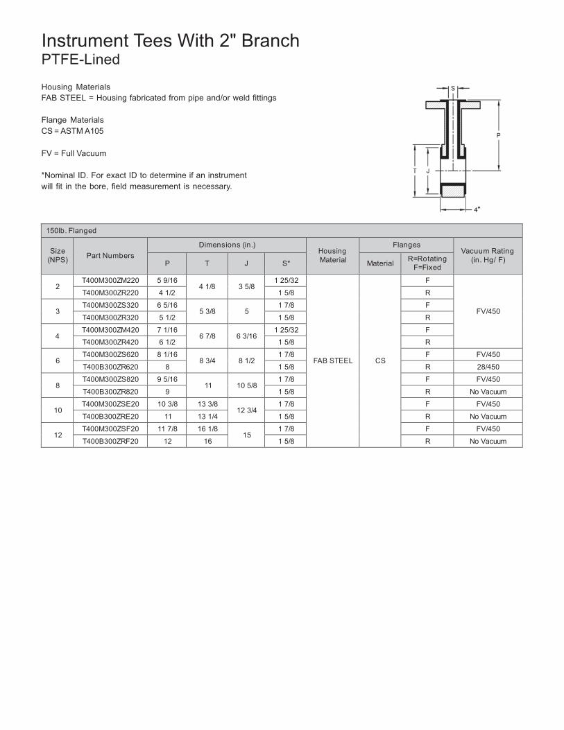
Instrument Tees With 2" Branch PTFE-Lined
Housing Materials FAB STEEL = Housing fabricated from pipe and/or weld fittings
Flange Materials CS = ASTM A105
FV = Full Vacuum
*Nominal ID. For exact ID to determine if an instrument will fit in the bore, field measurement is necessary.
150lb. Flanged
Size (NPS)
Part Numbers
Dimensions (in.) Housing Material
Flanges Vacuum Rating
(in. Hg/ F) P
T
J
S*
Material R=Rotating
F=Fixed
2 T400M300ZM220 5 9/16
4 1/8
3 5/8 1 25/32
FAB STEEL
CS
F
FV/450
T400M300ZR220 4 1/2 1 5/8 R
3 T400M300ZS320 6 5/16
5 3/8
5 1 7/8 F
T400M300ZR320 5 1/2 1 5/8 R
4 T400M300ZM420 7 1/16
6 7/8
6 3/16 1 25/32 F
T400M300ZR420 6 1/2 1 5/8 R
6 T400M300ZS620 8 1/16
8 3/4
8 1/2 1 7/8 F FV/450
T400B300ZR620 8 1 5/8 R 28/450
8 T400M300ZS820 9 5/16
11
10 5/8 1 7/8 F FV/450
T400B300ZR820 9 1 5/8 R No Vacuum
10 T400M300ZSE20 10 3/8 13 3/8
12 3/4 1 7/8 F FV/450
T400B300ZRE20 11 13 1/4 1 5/8 R No Vacuum
12 T400M300ZSF20 11 7/8 16 1/8
15 1 7/8 F FV/450
T400B300ZRF20 12 16 1 5/8 R No Vacuum
27
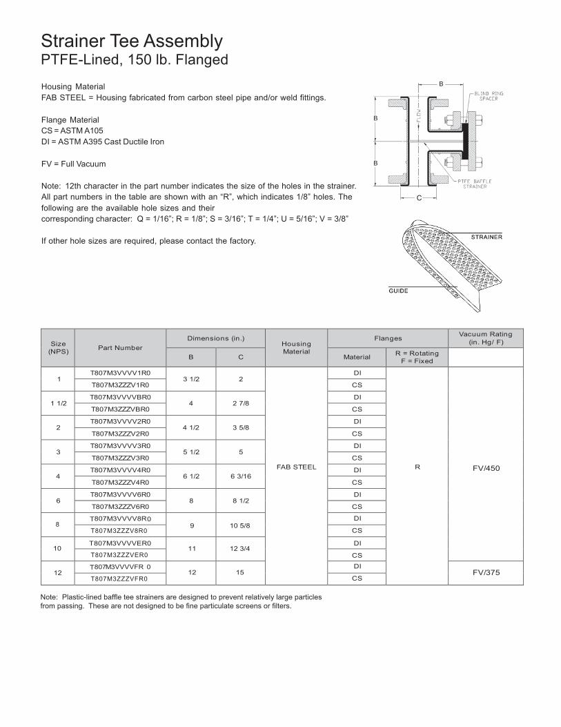
Strainer Tee Assembly PTFE-Lined, 150 lb. Flanged
Housing Material B
FAB STEEL = Housing fabricated from carbon steel pipe and/or weld fittings.
Flange Material B
CS = ASTM A105 DI = ASTM A395 Cast Ductile Iron
FV = Full Vacuum B
Note: 12th character in the part number indicates the size of the holes in the strainer. All part numbers in the table are shown with an “R”, which indicates 1/8” holes. The C following are the available hole sizes and their corresponding character: Q = 1/16”; R = 1/8”; S = 3/16”; T = 1/4”; U = 5/16”; V = 3/8”
If other hole sizes are required, please contact the factory.
Size (NPS)
Part Number
Dimensions (in.)
Housing Material
Flanges Vacuum Rating
(in. Hg/ F)
B
C
Material R = Rotating F = Fixed
1
T807M3VVVV1R0 3 1/2
2
FAB STEEL
DI
R
FV/450
T807M3ZZZV1R0 CS
1 1/2 T807M3VVVVBR0
4
2 7/8 DI
T807M3ZZZVBR0 CS
2 T807M3VVVV2R0
4 1/2
3 5/8 DI
T807M3ZZZV2R0 CS
3 T807M3VVVV3R0
5 1/2
5 DI
T807M3ZZZV3R0 CS
4 T807M3VVVV4R0
6 1/2
6 3/16 DI
T807M3ZZZV4R0 CS
6 T807M3VVVV6R0
8
8 1/2 DI
T807M3ZZZV6R0 CS
8 T807M3VVVV8R0
9
10 5/8 DI
T807M3ZZZV8R0 CS
10 T807M3VVVVER0
11
12 3/4 DI
T807M3ZZZVER0 CS
12 T807M3VVVVFR 0
12
15 DI
FV/375 T807M3ZZZVFR0 CS
Note: Plastic-lined baffle tee strainers are designed to prevent relatively large particles from passing. These are not designed to be fine particulate screens or filters.
28
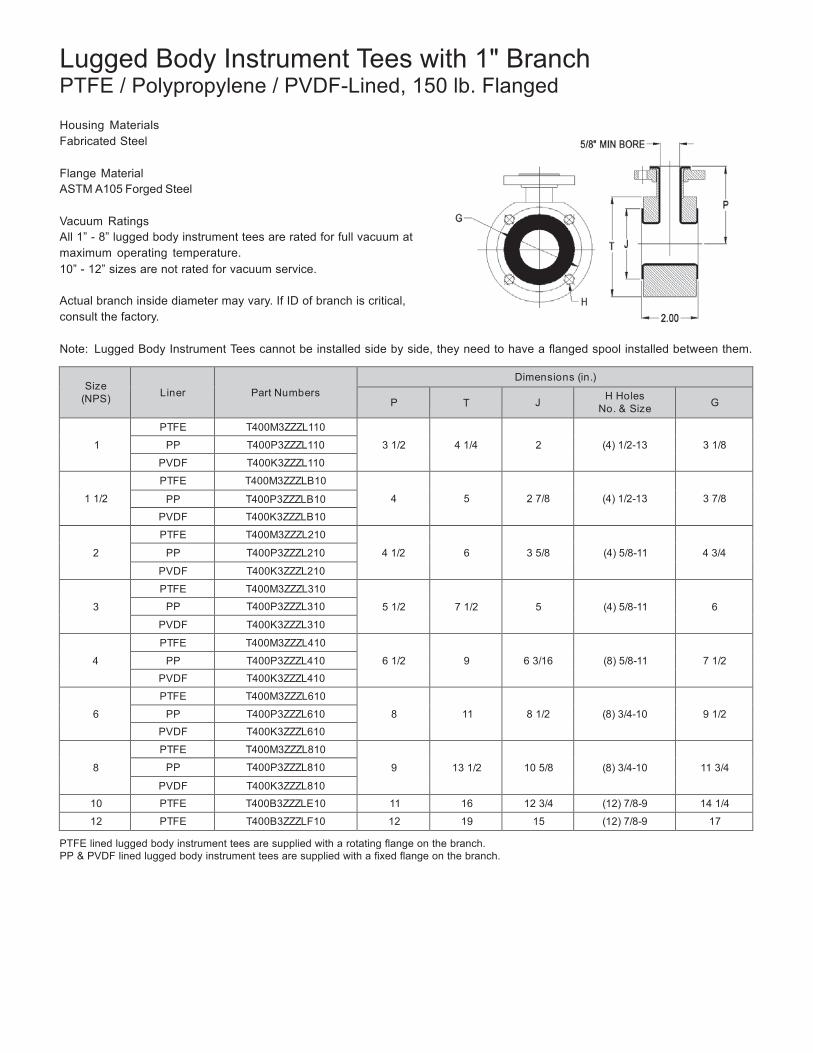
Lugged Body Instrument Tees with 1" Branch PTFE / Polypropylene / PVDF-Lined, 150 lb. Flanged
Housing Materials Fabricated Steel
Flange Material ASTM A105 Forged Steel
Vacuum Ratings All 1” - 8” lugged body instrument tees are rated for full vacuum at maximum operating temperature. 10” - 12” sizes are not rated for vacuum service.
Actual branch inside diameter may vary. If ID of branch is critical, consult the factory.
Note: Lugged Body Instrument Tees cannot be installed side by side, they need to have a flanged spool installed between them.
Size
(NPS)
Liner
Part Numbers
Dimensions (in.)
P
T
J H Holes No. & Size
G
1
PTFE T400M3ZZZL110
3 1/2
4 1/4
2
(4) 1/2-13
3 1/8 PP T400P3ZZZL110
PVDF T400K3ZZZL110
1 1/2
PTFE T400M3ZZZLB10
4
5
2 7/8
(4) 1/2-13
3 7/8 PP T400P3ZZZLB10
PVDF T400K3ZZZLB10
2
PTFE T400M3ZZZL210
4 1/2
6
3 5/8
(4) 5/8-11
4 3/4 PP T400P3ZZZL210
PVDF T400K3ZZZL210
3
PTFE T400M3ZZZL310
5 1/2
7 1/2
5
(4) 5/8-11
6 PP T400P3ZZZL310
PVDF T400K3ZZZL310
4
PTFE T400M3ZZZL410
6 1/2
9
6 3/16
(8) 5/8-11
7 1/2 PP T400P3ZZZL410
PVDF T400K3ZZZL410
6
PTFE T400M3ZZZL610
8
11
8 1/2
(8) 3/4-10
9 1/2 PP T400P3ZZZL610
PVDF T400K3ZZZL610
8
PTFE T400M3ZZZL810
9
13 1/2
10 5/8
(8) 3/4-10
11 3/4 PP T400P3ZZZL810
PVDF T400K3ZZZL810
10 PTFE T400B3ZZZLE10 11 16 12 3/4 (12) 7/8-9 14 1/4
12 PTFE T400B3ZZZLF10 12 19 15 (12) 7/8-9 17
PTFE lined lugged body instrument tees are supplied with a rotating flange on the branch. PP & PVDF lined lugged body instrument tees are supplied with a fixed flange on the branch.
29
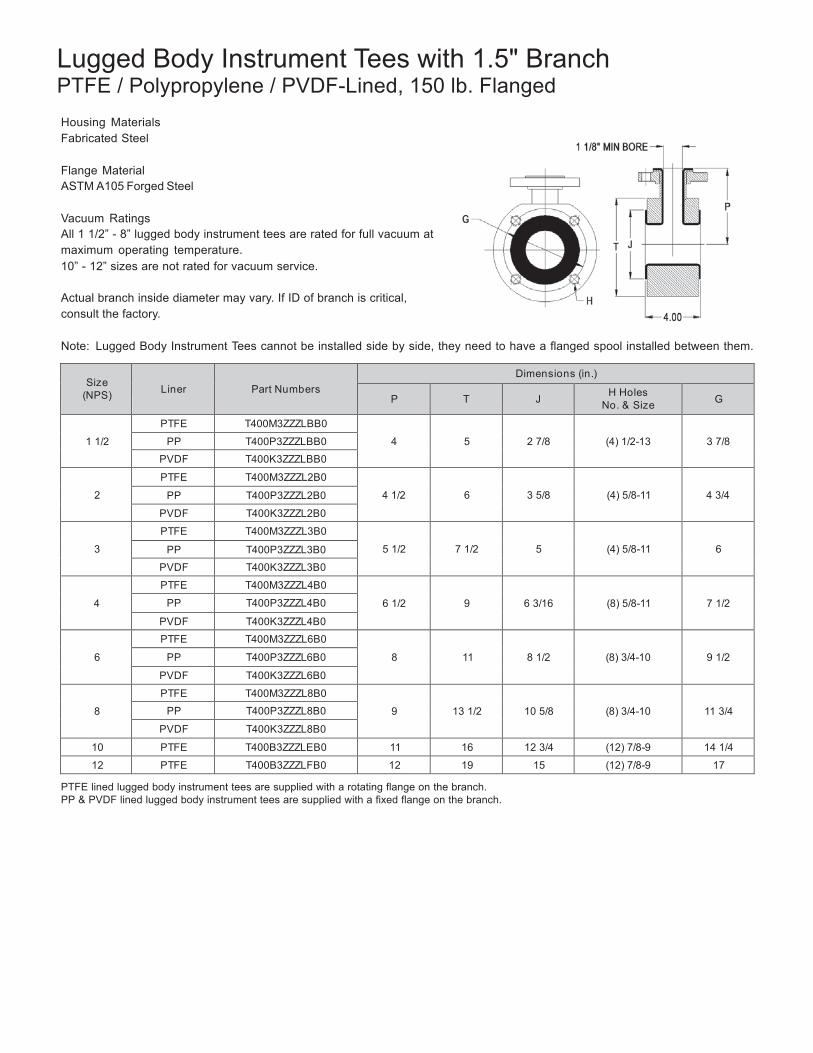
Lugged Body Instrument Tees with 1.5" Branch PTFE / Polypropylene / PVDF-Lined, 150 lb. Flanged
Housing Materials Fabricated Steel
Flange Material ASTM A105 Forged Steel
Vacuum Ratings All 1 1/2” - 8” lugged body instrument tees are rated for full vacuum at maximum operating temperature. 10” - 12” sizes are not rated for vacuum service.
Actual branch inside diameter may vary. If ID of branch is critical, consult the factory.
Note: Lugged Body Instrument Tees cannot be installed side by side, they need to have a flanged spool installed between them.
Size (NPS)
Liner
Part Numbers
Dimensions (in.)
P
T
J H Holes No. & Size
G
1 1/2
PTFE T400M3ZZZLBB0
4
5
2 7/8
(4) 1/2-13
3 7/8 PP T400P3ZZZLBB0
PVDF T400K3ZZZLBB0
2
PTFE T400M3ZZZL2B0
4 1/2
6
3 5/8
(4) 5/8-11
4 3/4 PP T400P3ZZZL2B0
PVDF T400K3ZZZL2B0
3
PTFE T400M3ZZZL3B0
5 1/2
7 1/2
5
(4) 5/8-11
6 PP T400P3ZZZL3B0
PVDF T400K3ZZZL3B0
4
PTFE T400M3ZZZL4B0
6 1/2
9
6 3/16
(8) 5/8-11
7 1/2 PP T400P3ZZZL4B0
PVDF T400K3ZZZL4B0
6
PTFE T400M3ZZZL6B0
8
11
8 1/2
(8) 3/4-10
9 1/2 PP T400P3ZZZL6B0
PVDF T400K3ZZZL6B0
8
PTFE T400M3ZZZL8B0
9
13 1/2
10 5/8
(8) 3/4-10
11 3/4 PP T400P3ZZZL8B0
PVDF T400K3ZZZL8B0
10 PTFE T400B3ZZZLEB0 11 16 12 3/4 (12) 7/8-9 14 1/4
12 PTFE T400B3ZZZLFB0 12 19 15 (12) 7/8-9 17
PTFE lined lugged body instrument tees are supplied with a rotating flange on the branch. PP & PVDF lined lugged body instrument tees are supplied with a fixed flange on the branch.
30
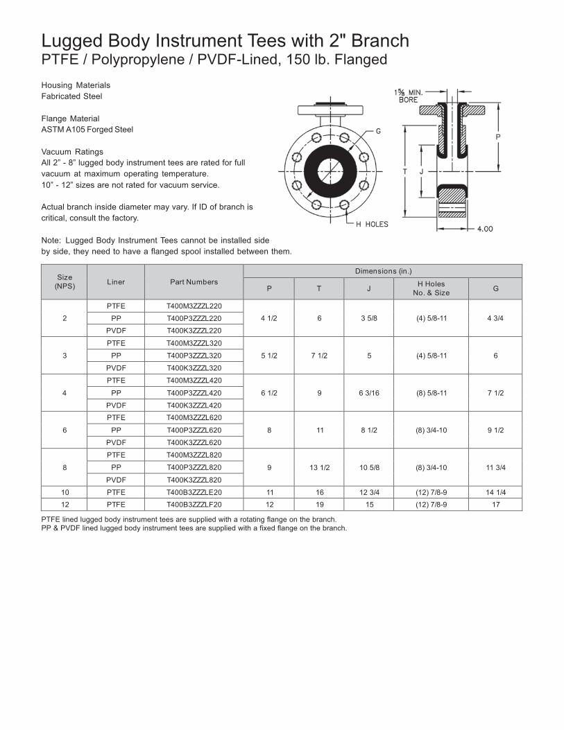
Lugged Body Instrument Tees with 2" Branch PTFE / Polypropylene / PVDF-Lined, 150 lb. Flanged
Housing Materials Fabricated Steel
Flange Material ASTM A105 Forged Steel
Vacuum Ratings All 2” - 8” lugged body instrument tees are rated for full vacuum at maximum operating temperature. 10” - 12” sizes are not rated for vacuum service.
Actual branch inside diameter may vary. If ID of branch is critical, consult the factory.
Note: Lugged Body Instrument Tees cannot be installed side by side, they need to have a flanged spool installed between them.
Size (NPS)
Liner
Part Numbers
Dimensions (in.)
P
T
J H Holes No. & Size
G
2
PTFE T400M3ZZZL220
4 1/2
6
3 5/8
(4) 5/8-11
4 3/4 PP T400P3ZZZL220
PVDF T400K3ZZZL220
3
PTFE T400M3ZZZL320
5 1/2
7 1/2
5
(4) 5/8-11
6 PP T400P3ZZZL320
PVDF T400K3ZZZL320
4
PTFE T400M3ZZZL420
6 1/2
9
6 3/16
(8) 5/8-11
7 1/2 PP T400P3ZZZL420
PVDF T400K3ZZZL420
6
PTFE T400M3ZZZL620
8
11
8 1/2
(8) 3/4-10
9 1/2 PP T400P3ZZZL620
PVDF T400K3ZZZL620
8
PTFE T400M3ZZZL820
9
13 1/2
10 5/8
(8) 3/4-10
11 3/4 PP T400P3ZZZL820
PVDF T400K3ZZZL820
10 PTFE T400B3ZZZLE20 11 16 12 3/4 (12) 7/8-9 14 1/4
12 PTFE T400B3ZZZLF20 12 19 15 (12) 7/8-9 17
PTFE lined lugged body instrument tees are supplied with a rotating flange on the branch. PP & PVDF lined lugged body instrument tees are supplied with a fixed flange on the branch.
31
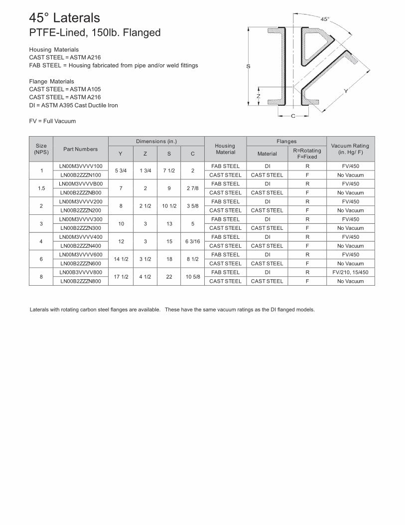
45° Laterals PTFE-Lined, 150lb. Flanged
Housing Materials CAST STEEL = ASTM A216 FAB STEEL = Housing fabricated from pipe and/or weld fittings
Flange Materials CAST STEEL = ASTM A105 CAST STEEL = ASTM A216 DI = ASTM A395 Cast Ductile Iron
FV = Full Vacuum
Size
(NPS)
Part Numbers
Dimensions (in.) Housing Material
Flanges Vacuum Rating
(in. Hg/ F)
Y
Z
S
C
Material R=Rotating F=Fixed
1
LN00M3VVVV100 5 3/4
1 3/4
7 1/2
2
FAB STEEL DI R FV/450
LN00B2ZZZN100 CAST STEEL CAST STEEL F No Vacuum
1.5 LN00M3VVVVB00
7
2
9
2 7/8 FAB STEEL DI R FV/450
LN00B2ZZZNB00 CAST STEEL CAST STEEL F No Vacuum
2 LN00M3VVVV200
8
2 1/2
10 1/2
3 5/8 FAB STEEL DI R FV/450
LN00B2ZZZN200 CAST STEEL CAST STEEL F No Vacuum
3 LN00M3VVVV300
10
3
13
5 FAB STEEL DI R FV/450
LN00B2ZZZN300 CAST STEEL CAST STEEL F No Vacuum
4 LN00M3VVVV400
12
3
15
6 3/16 FAB STEEL DI R FV/450
LN00B2ZZZN400 CAST STEEL CAST STEEL F No Vacuum
6 LN00M3VVVV600
14 1/2
3 1/2
18
8 1/2 FAB STEEL DI R FV/450
LN00B2ZZZN600 CAST STEEL CAST STEEL F No Vacuum
8 LN00B3VVVV800
17 1/2
4 1/2
22
10 5/8 FAB STEEL DI R FV/210, 15/450
LN00B2ZZZN800 CAST STEEL CAST STEEL F No Vacuum
Laterals with rotating carbon steel flanges are available. These have the same vacuum ratings as the DI flanged models.
32
000M3ZZ0RB10
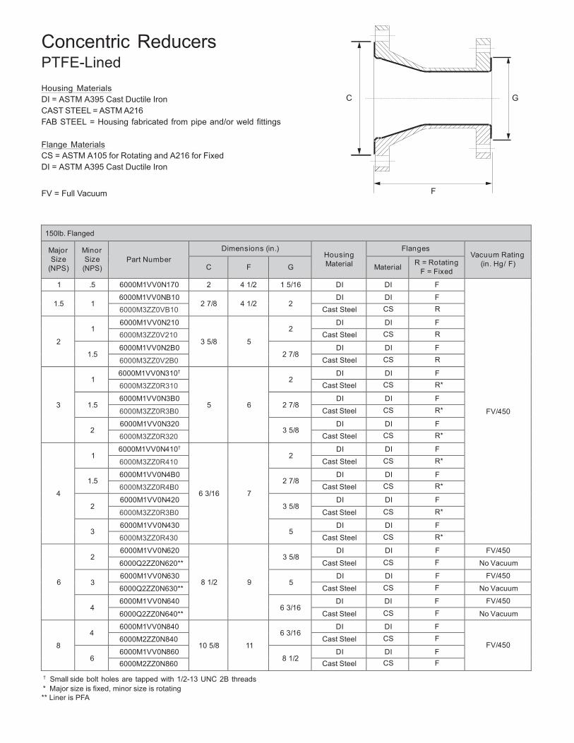
Concentric Reducers PTFE-Lined
Housing Materials DI = ASTM A395 Cast Ductile Iron C G CAST STEEL = ASTM A216 FAB STEEL = Housing fabricated from pipe and/or weld fittings
Flange Materials CS = ASTM A105 for Rotating and A216 for Fixed DI = ASTM A395 Cast Ductile Iron
FV = Full Vacuum F
150lb. Flanged
Major Size
(NPS)
Minor Size
(NPS)
Part Number
Dimensions (in.) Housing Material
Flanges Vacuum Rating
(in. Hg/ F)
C
F
G
Material R = Rotating F = Fixed
1 .5 6000M1VV0N170 2 4 1/2 1 5/16 DI DI F
FV/450
1.5
1
6000M1VV0NB10 2 7/8
4 1/2
2
DI DI F
6000M3ZZ0VB10 Cast Steel CS R
2
1
6000M1VV0N210
3 5/8
5
2
DI DI F
6000M3ZZ0V210 Cast Steel CS R
1.5 6000M1VV0N2B0
2 7/8 DI DI F
6000M3ZZ0V2B0 Cast Steel CS R
3
1
6000M1VV0N310†
5
6
2
DI DI F
6000M3ZZ0R310 Cast Steel CS R*
1.5 6000M1VV0N3B0
2 7/8 DI DI F
6000M3ZZ0R3B0 Cast Steel CS R*
2 6000M1VV0N320
3 5/8 DI DI F
6000M3ZZ0R320 Cast Steel CS R*
4
1
6000M1VV0N410†
6 3/16
7
2
DI DI F
6000M3ZZ0R410 Cast Steel CS R*
1.5 6000M1VV0N4B0
2 7/8 DI DI F
6000M3ZZ0R4B0 Cast Steel CS R*
2 6000M1VV0N420
3 5/8 DI DI F
6000M3ZZ0R3B0 Cast Steel CS R*
3 6000M1VV0N430
5 DI DI F
6000M3ZZ0R430 Cast Steel CS R*
6
2
6000M1VV0N620
8 1/2
9
3 5/8
DI DI F FV/450
6000Q2ZZ0N620** Cast Steel CS F No Vacuum
3 6000M1VV0N630
5 DI DI F FV/450
6000Q2ZZ0N630** Cast Steel CS F No Vacuum
4 6000M1VV0N640
6 3/16 DI DI F FV/450
6000Q2ZZ0N640** Cast Steel CS F No Vacuum
8
4
6000M1VV0N840
10 5/8
11
6 3/16
DI DI F
FV/450 6000M2ZZ0N840 Cast Steel CS F
6
6000M1VV0N860 8 1/2
DI DI F 6000M2ZZ0N860 Cast Steel CS F
† Small side bolt holes are tapped with 1/2-13 UNC 2B threads * Major size is fixed, minor size is rotating ** Liner is PFA
33
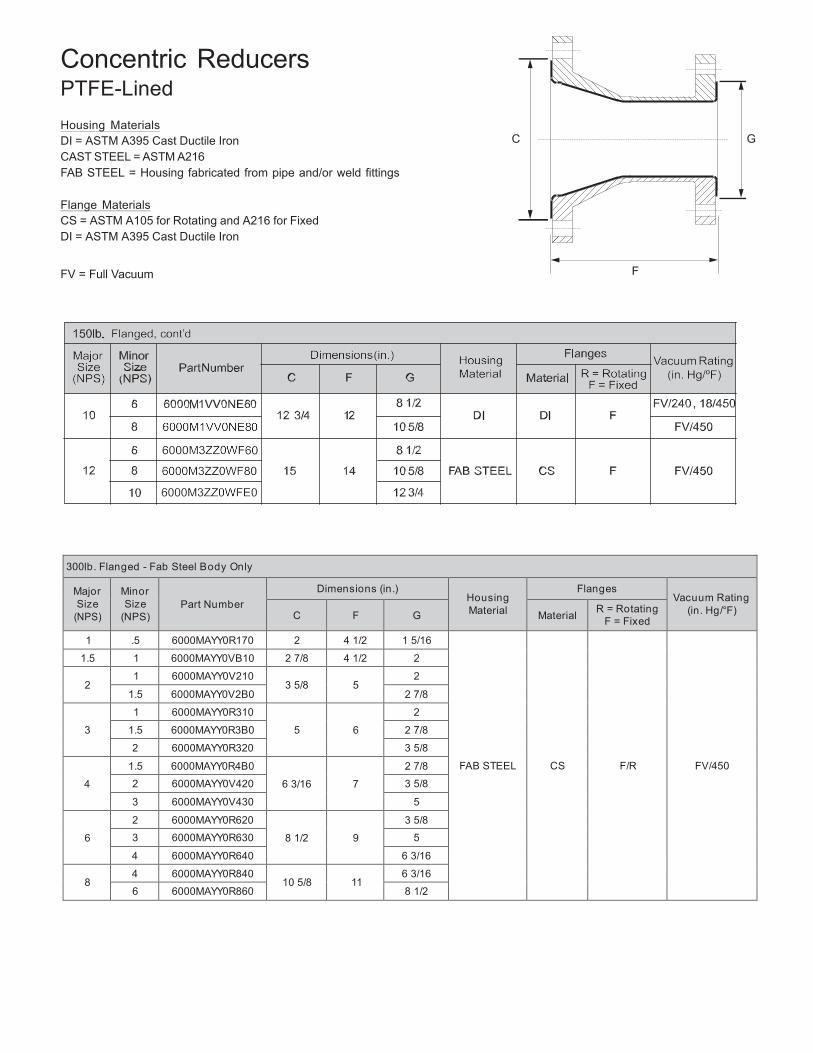
Concentric Reducers PTFE-Lined
Housing Materials DI = ASTM A395 Cast Ductile Iron C G CAST STEEL = ASTM A216 FAB STEEL = Housing fabricated from pipe and/or weld fittings
Flange Materials CS = ASTM A105 for Rotating and A216 for Fixed DI = ASTM A395 Cast Ductile Iron
FV = Full Vacuum F
300lb. Flanged - Fab Steel Body Only
Major Size
(NPS)
Minor Size
(NPS)
Part Number
Dimensions (in.) Housing Material
Flanges Vacuum Rating
(in. Hg/°F) C
F
G
Material R = Rotating
F = Fixed
1 .5 6000MAYY0R170 2 4 1/2 1 5/16
FAB STEEL
CS
F/R
FV/450
1.5 1 6000MAYY0VB10 2 7/8 4 1/2 2
2 1 6000MAYY0V210
3 5/8
5 2
1.5 6000MAYY0V2B0 2 7/8
3
1 6000MAYY0R310
5
6
2
1.5 6000MAYY0R3B0 2 7/8
2 6000MAYY0R320 3 5/8
4
1.5 6000MAYY0R4B0
6 3/16
7
2 7/8
2 6000MAYY0V420 3 5/8
3 6000MAYY0V430 5
6
2 6000MAYY0R620
8 1/2
9
3 5/8
3 6000MAYY0R630 5
4 6000MAYY0R640 6 3/16
8 4 6000MAYY0R840
10 5/8
11 6 3/16
6 6000MAYY0R860 8 1/2
34
Major Size
(NPS)
Minor Size
(NPS)
Part Numbers
Dimensions Housing Material
Flanges Vacuum Rating
o
C
F
G
Q
Material R=Rotating F=Fixed
1.5
1
8000M3ZZ0SB10 2 7/8
4 1/2
2
1/4
FAB STEEL CS F
FV/450
8000M2ZZ0NB10 CAST STEEL CAST STEEL
2 1 8000M2ZZ0N210
3 5/8
5 2 1/2 CAST STEEL CAST STEEL
F
FV/450 1.5 8000M2ZZ0N2B0 2 7/8 1/4 CAST STEEL CAST STEEL
3
1.5
8000M1VV0N3B0
5
6
2 7/8
3/4
DI DI
F
FV/450 8000M2ZZ0N3B0 CAST STEEL CAST STEEL
2
8000M1VV0N320 3 5/8
1/2
DI DI
8000M2ZZ0N320 CAST STEEL CAST STEEL
4
1.5 8000M2ZZ0N4B0*
6 3/16
7
2 7/8 1 1/4 CAST STEEL CAST STEEL
F
FV/450
2
8000M1VV0N420 3 5/8
1
DI DI
8000M2ZZ0N420 CAST STEEL CAST STEEL
3 8000M1VV0N430
5
1/2 DI DI
8000M2ZZ0N430 CAST STEEL CAST STEEL
6
3
8000M1VV0N630
8 1/2
9
5
1 1/2
DI DI
F
FV/450 8000M2ZZ0N630 CAST STEEL CAST STEEL
4
8000M1VV0N640 6 3/16
1
DI DI
8000M2ZZ0N640 CAST STEEL CAST STEEL 28/450
8
4
8000M1VV0N840
10 5/8
11
6 3/19
2
DI DI
F
FV/450
8000M2ZZ0N840 CAST STEEL CAST STEEL NO VACUUM
6 8000M1VV0N860
8 1/2
1 DI DI FV/450
8000M2ZZ0N860 CAST STEEL CAST STEEL NO VACUUM
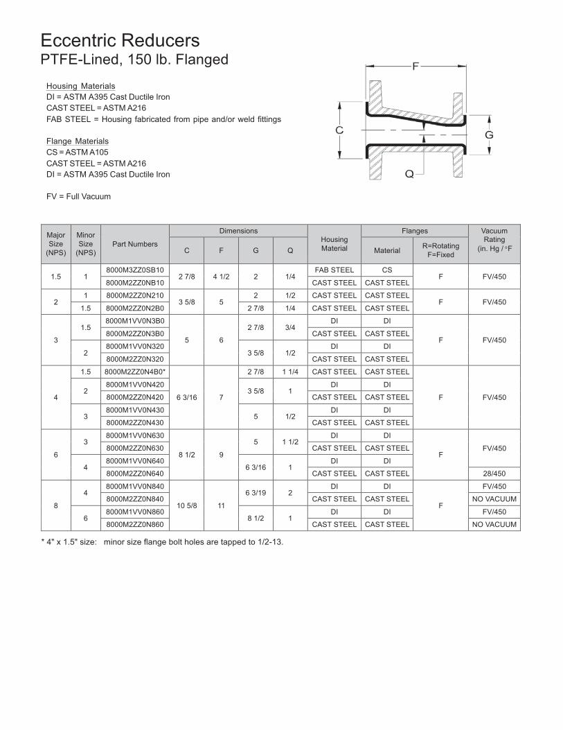
Eccentric Reducers PTFE-Lined, 150 lb. Flanged
Housing Materials DI = ASTM A395 Cast Ductile Iron CAST STEEL = ASTM A216 FAB STEEL = Housing fabricated from pipe and/or weld fittings
Flange Materials CS = ASTM A105 CAST STEEL = ASTM A216 DI = ASTM A395 Cast Ductile Iron
FV = Full Vacuum
(in. Hg / F
* 4" x 1.5" size: minor size flange bolt holes are tapped to 1/2-13.
35
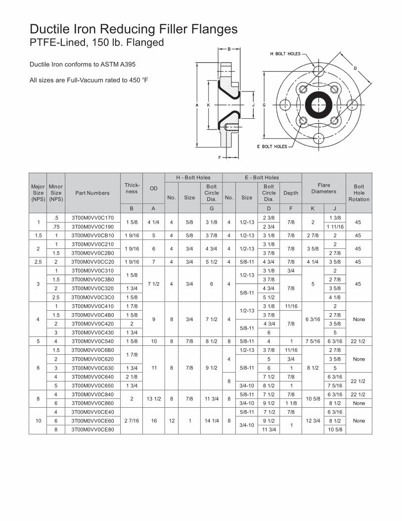
Ductile Iron Reducing Filler Flanges PTFE-Lined, 150 lb. Flanged
Ductile Iron conforms to ASTM A395
All sizes are Full-Vacuum rated to 450 oF
Major Size
(NPS)
Minor Size
(NPS)
Part Numbers
Thick- ness
OD
H - Bolt Holes E - Bolt Holes Flare
Diameters
Bolt Hole
Rotation
No.
Size
Bolt Circle Dia.
No.
Size
Bolt Circle Dia.
Depth
B A G D F K J
1 .5 3T00M0VV0C170
1 5/8
4 1/4
4
5/8
3 1/8
4
1/2-13 2 3/8
7/8
2 1 3/8
45 .75 3T00M0VV0C190 2 3/4 1 11/16
1.5 1 3T00M0VV0CB10 1 9/16 5 4 5/8 3 7/8 4 1/2-13 3 1/8 7/8 2 7/8 2 45
2 1 3T00M0VV0C210
1 9/16
6
4
3/4
4 3/4
4
1/2-13 3 1/8
7/8
3 5/8 2
45 1.5 3T00M0VV0C2B0 3 7/8 2 7/8
2.5 2 3T00M0VV0CC20 1 9/16 7 4 3/4 5 1/2 4 5/8-11 4 3/4 7/8 4 1/4 3 5/8 45
3
1 3T00M0VV0C310 1 5/8
7 1/2
4
3/4
6
4
1/2-13
3 1/8 3/4
5
2
45 1.5 3T00M0VV0C3B0 3 7/8
7/8
2 7/8
2 3T00M0VV0C320 1 3/4 5/8-11
4 3/4 3 5/8
2.5 3T00M0VV0C3C0 1 5/8 5 1/2 4 1/8
4
1 3T00M0VV0C410 1 7/8
9
8
3/4
7 1/2
4
1/2-13
3 1/8 11/16
6 3/16
2
None 1.5 3T00M0VV0C4B0 1 5/8 3 7/8
7/8
2 7/8
2 3T00M0VV0C420 2 5/8-11
4 3/4 3 5/8
3 3T00M0VV0C430 1 3/4 6 5
5 4 3T00M0VV0C540 1 5/8 10 8 7/8 8 1/2 8 5/8-11 4 1 7 5/16 6 3/16 22 1/2
6
1.5 3T00M0VV0C6B0 1 7/8
11
8
7/8
9 1/2
4
1/2-13 3 7/8 11/16
8 1/2
2 7/8
None 2 3T00M0VV0C620
5/8-11
5 3/4 3 5/8
3 3T00M0VV0C630 1 3/4 6 1 5
4 3T00M0VV0C640 2 1/8 8
7 1/2 7/8 6 3/16 22 1/2
5 3T00M0VV0C650 1 3/4 3/4-10 8 1/2 1 7 5/16
8 4 3T00M0VV0C840
2
13 1/2
8
7/8
11 3/4
8 5/8-11 7 1/2 7/8
10 5/8 6 3/16 22 1/2
6 3T00M0VV0C860 3/4-10 9 1/2 1 1/8 8 1/2 None
10
4 3T00M0VV0CE40
2 7/16
16
12
1
14 1/4
8
5/8-11 7 1/2 7/8
12 3/4
6 3/16
None 6 3T00M0VV0CE60
3/4-10 9 1/2
1 8 1/2
8 3T00M0VV0CE80 11 3/4 10 5/8
36
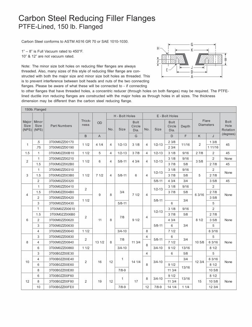
Carbon Steel Reducing Filler Flanges PTFE-Lined, 150 lb. Flanged
Carbon Steel conforms to ASTM A516 GR 70 or SAE 1010-1030.
1” – 8” is Full Vacuum rated to 450°F. 10” & 12” are not vacuum rated.
Note: The minor size bolt holes on reducing filler flanges are always threaded. Also, many sizes of this style of reducing filler flange are con- structed with both the major size and minor size bolt holes as threaded. This is to prevent interference between bolt heads and nuts of the two connecting flanges. Please be aware of what these will be connected to - if connecting to other flanges that have threaded holes, a concentric reducer (through holes on both flanges) may be required. The PTFE- lined ductile iron reducing flanges are constructed with the major holes as through holes in all sizes. The thickness dimension may be different than the carbon steel reducing flange.
150lb. Flanged Major Size
(NPS)
Minor Size
(NPS)
Part Numbers
Thick- ness
OD
H - Bolt Holes E - Bolt Holes
Flare
Diameters
Bolt Hole
Rotation (degrees)
No.
Size
Bolt Circle Dia.
No.
Size
Bolt Circle Dia.
Depth
B A G D F K J
1 .5 3T00M0ZZ00170
1 1/2
4 1/4
4
1/2-13
3 1/8
4
1/2-13 2 3/8
11/16
2 1 3/8
45 .75 3T00M0ZZ00190 2 3/4 1 11/16
1.5 1 3T00M0ZZ00B10 1 1/2 5 4 1/2-13 3 7/8 4 1/2-13 3 1/8 9/16 2 7/8 2 45
2 1 3T00M0ZZ00210
1 1/2
6
4
5/8-11
4 3/4
4
1/2-13 3 1/8 9/16
3 5/8 2 None
1.5 3T00M0ZZ002B0 3 7/8 5/8 2 7/8 45
3
1 3T00M0ZZ00310
1 1/2
7 1/2
4
5/8-11
6
4
1/2-13
3 1/8 9/16
5
2 None
1.5 3T00M0ZZ003B0 3 7/8 5/8 2 7/8
2 3T00M0ZZ00320 5/8-11 4 3/4 3/4 3 5/8 45
4
1 3T00M0ZZ00410 2
9
8
3/4
7 1/2
4
1/2-13
3 1/8 9/16
6 3/16
2
None 1.5 3T00M0ZZ004B0 3 7/8 5/8 2 7/8
2 3T00M0ZZ00420 1 1/2
5/8-11
3/4
3 5/8
3 3T00M0ZZ00430 5/8-11 6 5
6
1 3T00M0ZZ00610
2
11
8
7/8
9 1/2
4
1/2-13
3 1/8 9/16
8 1/2
2
None
1.5 3T00M0ZZ006B0 3 7/8 5/8 2 7/8
2 3T00M0ZZ00620
5/8-11
4 3/4
3/4
3 5/8
3 3T00M0ZZ00630 6 5
4 3T00M0ZZ00640 1 1/2 3/4-10 8 7 1/2 6 3/16
8
3 3T00M0ZZ00830 2
13 1/2
8
7/8
11 3/4
4 5/8-11
6 3/4
10 5/8
5
None 4 3T00M0ZZ00840
8 7 1/2 6 3/16
6 3T00M0ZZ00860 1 1/2 3/4-10 3/4-10 9 1/2 13/16 8 1/2
10
3 3T00B0ZZ00E30
2
16
12
1
14 1/4
4
3/4-10
6 5/8
12 3/4
5
None 4 3T00B0ZZ00E40
8
3/4 6 3/16
6 3T00B0ZZ00E60 9 1/2 13/16
8 1/2
8 3T00B0ZZ00E80 7/8-9 11 3/4 10 5/8
12
6 3T00B0ZZ00F60
2
19
12
1
17
8
3/4-10
9 1/2 13/16
15
8 1/2
None 8 3T00B0ZZ00F80 11 3/4 10 5/8
10 3T00B0ZZ00FE0 7/8-9 12 7/8-9 14 1/4 1 1/4 12 3/4
37
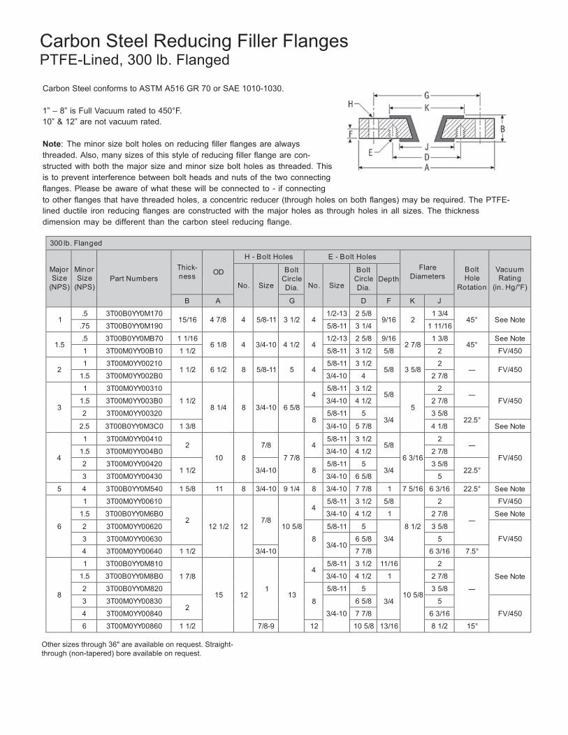
Carbon Steel Reducing Filler Flanges PTFE-Lined, 300 lb. Flanged
Carbon Steel conforms to ASTM A516 GR 70 or SAE 1010-1030.
1” – 8” is Full Vacuum rated to 450°F. 10” & 12” are not vacuum rated.
Note: The minor size bolt holes on reducing filler flanges are always threaded. Also, many sizes of this style of reducing filler flange are con- structed with both the major size and minor size bolt holes as threaded. This is to prevent interference between bolt heads and nuts of the two connecting flanges. Please be aware of what these will be connected to - if connecting to other flanges that have threaded holes, a concentric reducer (through holes on both flanges) may be required. The PTFE- lined ductile iron reducing flanges are constructed with the major holes as through holes in all sizes. The thickness dimension may be different than the carbon steel reducing flange.
300 lb. Flanged
Major Size
(NPS)
Minor Size
(NPS)
Part Numbers
Thick- ness
OD
H - Bolt Holes E - Bolt Holes Flare
Diameters
Bolt Hole
Rotation
Vacuum Rating
(in. Hg/°F)
No.
Size
Bolt Circle Dia.
No.
Size
Bolt Circle Dia.
Depth
B A G D F K J
1 .5 3T00B0YY0M170
15/16
4 7/8
4 5/8-11
3 1/2
4
1/2-13 2 5/8 9/16
2
1 3/4 45°
See Note
.75 3T00B0YY0M190 5/8-11 3 1/4 1 11/16
1.5 .5 3T00B0YY0MB70 1 1/16
6 1/8
4 3/4-10
4 1/2
4
1/2-13 2 5/8 9/16 2 7/8
1 3/8 45°
See Note
1 3T00M0YY00B10 1 1/2 5/8-11 3 1/2 5/8 2 FV/450
2 1 3T00M0YY00210
1 1/2
6 1/2
8 5/8-11
5
4
5/8-11 3 1/2 5/8
3 5/8
2 ---
FV/450
1.5 3T00M0YY002B0 3/4-10 4 2 7/8
3
1 3T00M0YY00310
1 1/2
8 1/4
8
3/4-10
6 5/8
4
5/8-11 3 1/2 5/8
5
2 ---
FV/450 1.5 3T00M0YY003B0 3/4-10 4 1/2 2 7/8
2 3T00M0YY00320 8
5/8-11 5 3/4
3 5/8 22.5°
2.5 3T00B0YY0M3C0 1 3/8 3/4-10 5 7/8 4 1/8 See Note
4
1 3T00M0YY00410 2
10
8
7/8
7 7/8
4
5/8-11 3 1/2 5/8
6 3/16
2 ---
FV/450 1.5 3T00M0YY004B0 3/4-10 4 1/2 2 7/8
2 3T00M0YY00420 1 1/2
3/4-10
8
5/8-11 5 3/4
3 5/8 22.5°
3 3T00M0YY00430 3/4-10 6 5/8 5
5 4 3T00B0YY0M540 1 5/8 11 8 3/4-10 9 1/4 8 3/4-10 7 7/8 1 7 5/16 6 3/16 22.5° See Note
6
1 3T00M0YY00610
2
12 1/2
12
7/8
10 5/8
4
5/8-11 3 1/2 5/8 8 1/2
2
---
FV/450
1.5 3T00B0YY0M6B0 3/4-10 4 1/2 1 2 7/8 See Note
2 3T00M0YY00620
8
5/8-11 5
3/4
3 5/8
FV/450 3 3T00M0YY00630
3/4-10 6 5/8 5
4 3T00M0YY00640 1 1/2 3/4-10 7 7/8 6 3/16 7.5°
8
1 3T00B0YY0M810
1 7/8
15
12
1
13
4
5/8-11 3 1/2 11/16 10 5/8
2
---
See Note 1.5 3T00B0YY0M8B0 3/4-10 4 1/2 1 2 7/8
2 3T00B0YY0M820
8
5/8-11 5
3/4
3 5/8
3 3T00M0YY00830 2
3/4-10
6 5/8 5
FV/450 4 3T00M0YY00840 7 7/8 6 3/16
6 3T00M0YY00860 1 1/2 7/8-9 12 10 5/8 13/16 8 1/2 15°
Other sizes through 36" are available on request. Straight-through (non-tapered) bore available on request.
38
Major Size (NPS
Minor Size
(NPS)
Part Numbers
Thick- ness
OD
H - Bolt Holes E - Bolt Holes Flare
Diameters
Bolt Hole
Rotation
No.
Size
Bolt Circle Dia.
No.
Size
Bolt Circle Dia.
Depth
B A G D F C J
1.5
.5 3T00B0ZZ0MB70
13/16
5
4
1/2-13
3 7/8
4
1/2-13
2 3/8 7/16
2 7/8
1 3/8
45 .75 3T00B0ZZ0MB90 2 3/4
1/2 1 11/16
1.25 3T00B0ZZ0MBA0 3 1/2 2 1/2
2
.5 3T00B0ZZ0M270
7/8
6
4
5/8-11
4 3/4
4
1/2-13
2 3/8
1/2
3 5/8
1 3/8
45 .75 3T00B0ZZ0M290 2 3/4 1 11/16
1.25 3T00B0ZZ0M2A0 3 1/2 2 1/2
2.5
1 3T00B0ZZ0MC10
1
7
4
3/4
5 1/2
4
1/2-13
3 1/8 5/8
4 1/8
2 ---
1.5 3T00B0ZZ0MCB0 5/8-11 3 7/8 2 7/8 45
2 3T00B0ZZ0MC20 3/4 5/8-11 4 3/4 9/16 3 5/8
3 1.25 3T00B0ZZ0M3A0
1 3/16
7 1/2
4
5/8-11
6
4 1/2-13 3 1/2 1/2
5 2 1/2
45 2.5 3T00B0ZZ0M3C0 5/8-11 5 1/2 11/16 4 1/8
5
2 3T00B0ZZ0M520 1 3/16
10
8
7/8 8 1/2
4
5/8-11
4 3/4 11/16
7 5/16
3 5/8 ---
3 3T00B0ZZ0M530 3/4-10 6 5
6 .75 3T00B0ZZ0M690 1 1/4 11 8 7/8 9 1/2 4 1/2-13 2 3/4 11/16 8 1/2 1 11/16 ---
8
1 3T00B0ZZ0M810
1 3/8
13 1/2
8
7/8
11 3/4
4
1/2-13
3 1/8 11/16
10 5/8
2
---- 1.5 3T00B0ZZ0M8B0 3 7/8 5/8 2 7/8
2 3T00B0ZZ0M820 5/8-11 4 3/4 11/16 3 5/8
10
1 3T00B0ZZ0ME10
1 7/16
16
12
1
14 1/4
4
1/2-13
3 1/8 3/4
12 3/4
2
--- 1.5 3T00B0ZZ0MEB0 3 7/8 11/16 2 7/8
2 3T00B0ZZ0ME20 5/8-11
4 3/4 3/4
3 5/8
4 3T00B0ZZ0ME40 8 7 1/2 6 3/16
12
1 3T00B0ZZ0MF10
1 1/2
19
12
1
17
4
1/2-13
3 1/8 7/8
15
2
---
1.5 3T00B0ZZ0MFB0 3 7/8
3/4
2 7/8
2 3T00B0ZZ0MF20
5/8-11
4 3/4 3 5/8
3 3T00B0ZZ0MF30 6 5
4 3T00B0ZZ0MF40 8 7 1/2 6 3/16
14
2 3T00B0ZZ0MG20
1 5/8
21
12
1 1/8
18 3/4
4 5/8-11
4 3/4 11/16
16 1/4
3 5/8
---
4 3T00B0ZZ0MG40
8
7 1/2 3/4 6 3/16
6 3T00B0ZZ0MG60 3/4-10
9 1/2 1
8 1/2
8 3T00B0ZZ0MG80 11 3/4 10 5/8
10 3T00B0ZZ0MGE0 12
7/8-9
14 1/4 7/8
12 3/4
12 3T00B0ZZ0MGF0 1-8 17 15 15
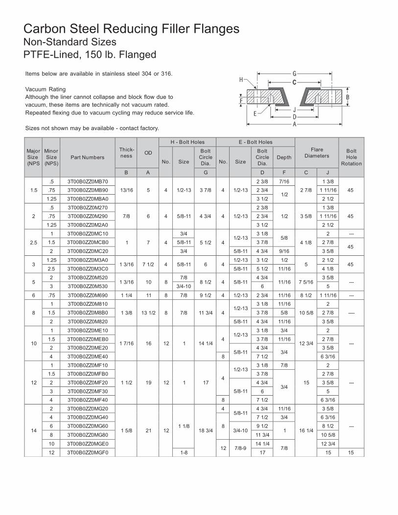
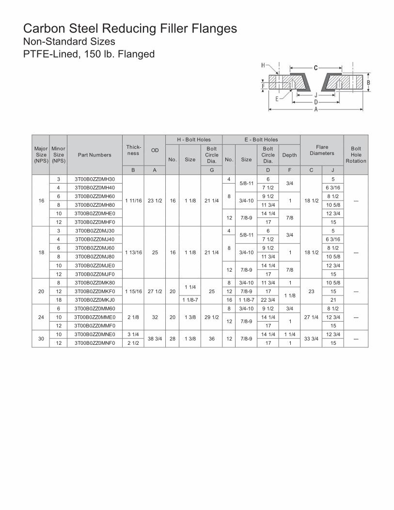
Carbon Steel Reducing Filler Flanges Non-Standard Sizes PTFE-Lined, 150 lb. Flanged
Items below are available in stainless steel 304 or 316.
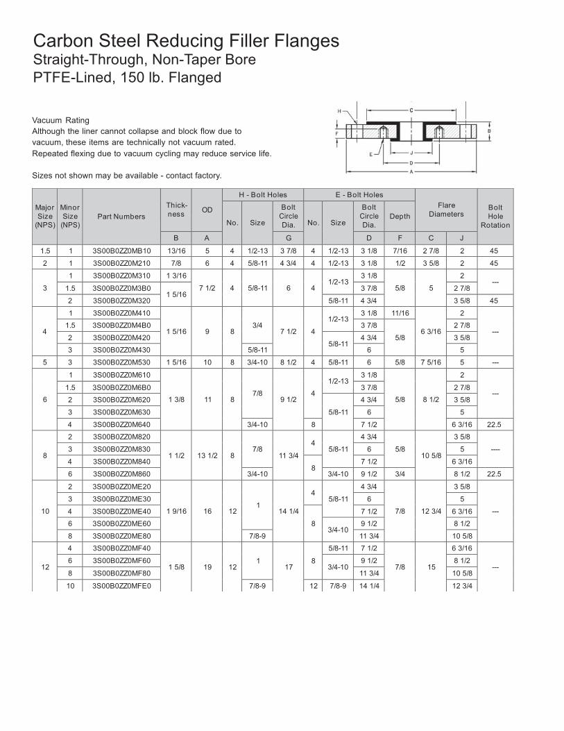
Vacuum Rating Although the liner cannot collapse and block flow due to vacuum, these items are technically not vacuum rated. Repeated flexing due to vacuum cycling may reduce service life.
Sizes not shown may be available - contact factory.
39
Carbon Steel Reducing Filler Flanges Non-Standard Sizes PTFE-Lined, 150 lb. Flanged
Major Size
(NPS)
Minor Size
(NPS)
Part Numbers
Thick- ness
OD
H - Bolt Holes E - Bolt Holes Flare
Diameters
Bolt Hole
Rotation
No.
Size
Bolt Circle Dia.
No.
Size
Bolt Circle Dia.
Depth
B A G D F C J
16
3 3T00B0ZZ0MH30
1 11/16
23 1/2
16
1 1/8
21 1/4
4 5/8-11
6 3/4
18 1/2
5
---
4 3T00B0ZZ0MH40
8
7 1/2 6 3/16
6 3T00B0ZZ0MH60 3/4-10
9 1/2 1
8 1/2
8 3T00B0ZZ0MH80 11 3/4 10 5/8
10 3T00B0ZZ0MHE0 12
7/8-9
14 1/4 7/8
12 3/4
12 3T00B0ZZ0MHF0 17 15
18
3 3T00B0ZZ0MJ30
1 13/16
25
16
1 1/8
21 1/4
4 5/8-11
6 3/4
18 1/2
5
---
4 3T00B0ZZ0MJ40
8
7 1/2 6 3/16
6 3T00B0ZZ0MJ60 3/4-10
9 1/2 1
8 1/2
8 3T00B0ZZ0MJ80 11 3/4 10 5/8
10 3T00B0ZZ0MJE0 12
7/8-9
14 1/4 7/8
12 3/4
12 3T00B0ZZ0MJF0 17 15
20
8 3T00B0ZZ0MK80
1 15/16
27 1/2
20
1 1/4
25
8 3/4-10 11 3/4 1
23
10 5/8
--- 12 3T00B0ZZ0MKF0 12 7/8-9 17
1 1/8 15
18 3T00B0ZZ0MKJ0 1 1/8-7 16 1 1/8-7 22 3/4 21
24
6 3T00B0ZZ0MM60
2 1/8
32
20
1 3/8
29 1/2
8 3/4-10 9 1/2 3/4
27 1/4
8 1/2
--- 10 3T00B0ZZ0MME0
12
7/8-9 14 1/4
1 12 3/4
12 3T00B0ZZ0MMF0 17 15
30 10 3T00B0ZZ0MNE0 3 1/4
38 3/4
28
1 3/8
36
12
7/8-9 14 1/4 1 1/4
33 3/4 12 3/4
--- 12 3T00B0ZZ0MNF0 2 1/2 17 1 15
40
Major Size
(NPS)
Minor Size
(NPS)
Part Numbers
Thick- ness
OD
H - Bolt Holes E - Bolt Holes Flare
Diameters
Bolt Hole
Rotation
No.
Size
Bolt Circle Dia.
No.
Size
Bolt Circle Dia.
Depth
B A G D F C J
1.5 1 3S00B0ZZ0MB10 13/16 5 4 1/2-13 3 7/8 4 1/2-13 3 1/8 7/16 2 7/8 2 45
2 1 3S00B0ZZ0M210 7/8 6 4 5/8-11 4 3/4 4 1/2-13 3 1/8 1/2 3 5/8 2 45
3
1 3S00B0ZZ0M310 1 3/16
7 1/2
4
5/8-11
6
4
1/2-13
3 1/8
5/8
5
2 ---
1.5 3S00B0ZZ0M3B0 1 5/16
3 7/8 2 7/8
2 3S00B0ZZ0M320 5/8-11 4 3/4 3 5/8 45
4
1 3S00B0ZZ0M410
1 5/16
9
8
3/4
7 1/2
4
1/2-13
3 1/8 11/16
6 3/16
2
--- 1.5 3S00B0ZZ0M4B0 3 7/8
5/8
2 7/8
2 3S00B0ZZ0M420 5/8-11
4 3/4 3 5/8
3 3S00B0ZZ0M430 5/8-11 6 5
5 3 3S00B0ZZ0M530 1 5/16 10 8 3/4-10 8 1/2 4 5/8-11 6 5/8 7 5/16 5 ---
6
1 3S00B0ZZ0M610
1 3/8
11
8
7/8
9 1/2
4
1/2-13
3 1/8
5/8
8 1/2
2
--- 1.5 3S00B0ZZ0M6B0 3 7/8 2 7/8
2 3S00B0ZZ0M620
5/8-11
4 3/4 3 5/8
3 3S00B0ZZ0M630 6 5
4 3S00B0ZZ0M640 3/4-10 8 7 1/2 6 3/16 22.5
8
2 3S00B0ZZ0M820
1 1/2
13 1/2
8
7/8
11 3/4
4
5/8-11
4 3/4
5/8
10 5/8
3 5/8
---- 3 3S00B0ZZ0M830 6 5
4 3S00B0ZZ0M840 8
7 1/2 6 3/16
6 3S00B0ZZ0M860 3/4-10 3/4-10 9 1/2 3/4 8 1/2 22.5
10
2 3S00B0ZZ0ME20
1 9/16
16
12
1
14 1/4
4
5/8-11
4 3/4
7/8
12 3/4
3 5/8
---
3 3S00B0ZZ0ME30 6 5
4 3S00B0ZZ0ME40
8
7 1/2 6 3/16
6 3S00B0ZZ0ME60 3/4-10
9 1/2 8 1/2
8 3S00B0ZZ0ME80 7/8-9 11 3/4 10 5/8
12
4 3S00B0ZZ0MF40
1 5/8
19
12
1
17
8
5/8-11 7 1/2
7/8
15
6 3/16
--- 6 3S00B0ZZ0MF60
3/4-10 9 1/2 8 1/2
8 3S00B0ZZ0MF80 11 3/4 10 5/8
10 3S00B0ZZ0MFE0 7/8-9 12 7/8-9 14 1/4 12 3/4
Carbon Steel Reducing Filler Flanges Straight-Through, Non-Taper Bore PTFE-Lined, 150 lb. Flanged
Vacuum Rating Although the liner cannot collapse and block flow due to vacuum, these items are technically not vacuum rated. Repeated flexing due to vacuum cycling may reduce service life.
Sizes not shown may be available - contact factory.
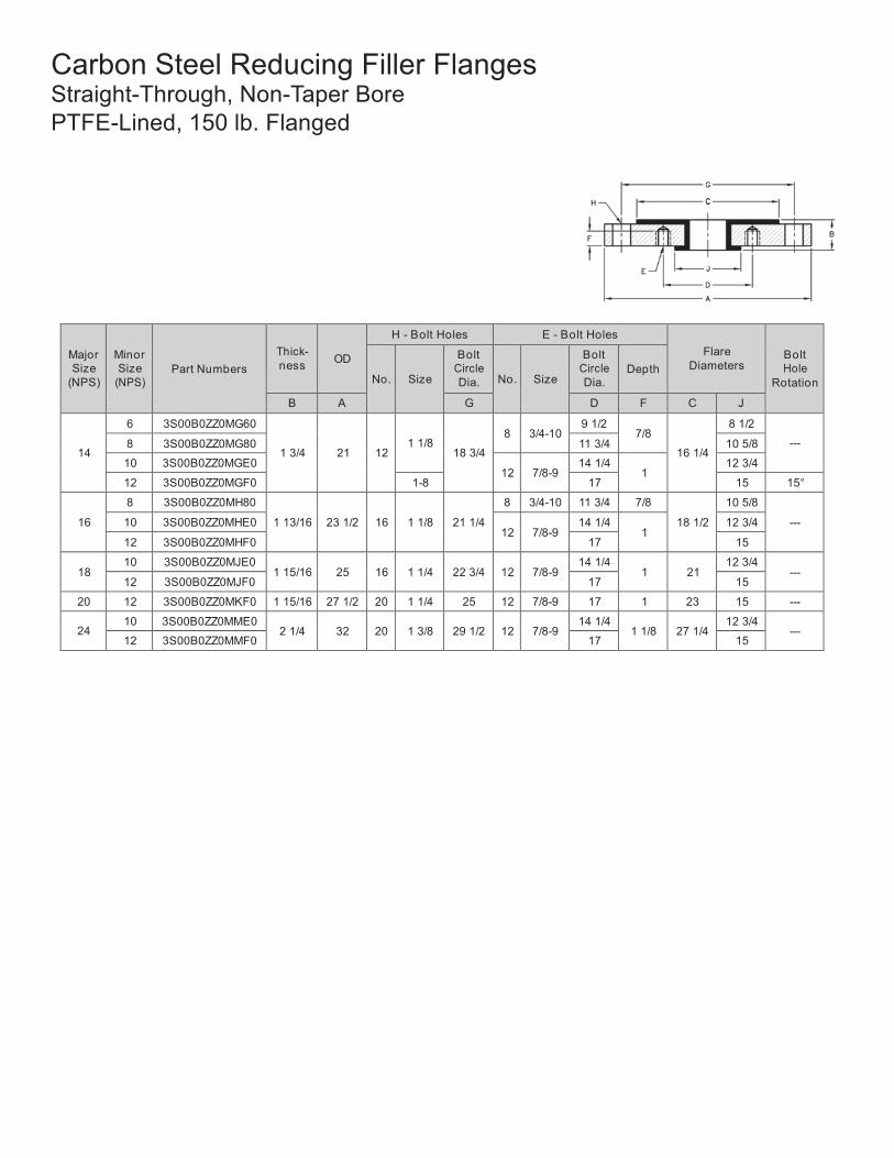
41
Carbon Steel Reducing Filler Flanges Straight-Through, Non-Taper Bore PTFE-Lined, 150 lb. Flanged
Major Size
(NPS)
Minor Size
(NPS)
Part Numbers
Thick- ness
OD
H - Bolt Holes E - Bolt Holes Flare
Diameters
Bolt Hole
Rotation
No.
Size
Bolt Circle Dia.
No.
Size
Bolt Circle Dia.
Depth
B A G D F C J
14
6 3S00B0ZZ0MG60
1 3/4
21
12
1 1/8
18 3/4
8
3/4-10
9 1/2 7/8
16 1/4
8 1/2
--- 8 3S00B0ZZ0MG80 11 3/4 10 5/8
10 3S00B0ZZ0MGE0 12
7/8-9
14 1/4 1
12 3/4
12 3S00B0ZZ0MGF0 1-8 17 15 15°
16
8 3S00B0ZZ0MH80
1 13/16
23 1/2
16
1 1/8
21 1/4
8 3/4-10 11 3/4 7/8
18 1/2
10 5/8
--- 10 3S00B0ZZ0MHE0
12
7/8-9 14 1/4
1 12 3/4
12 3S00B0ZZ0MHF0 17 15
18 10 3S00B0ZZ0MJE0
1 15/16
25
16
1 1/4
22 3/4
12
7/8-9 14 1/4
1
21 12 3/4
--- 12 3S00B0ZZ0MJF0 17 15
20 12 3S00B0ZZ0MKF0 1 15/16 27 1/2 20 1 1/4 25 12 7/8-9 17 1 23 15 ---
24 10 3S00B0ZZ0MME0
2 1/4
32
20
1 3/8
29 1/2
12
7/8-9 14 1/4
1 1/8
27 1/4 12 3/4
--- 12 3S00B0ZZ0MMF0 17 15
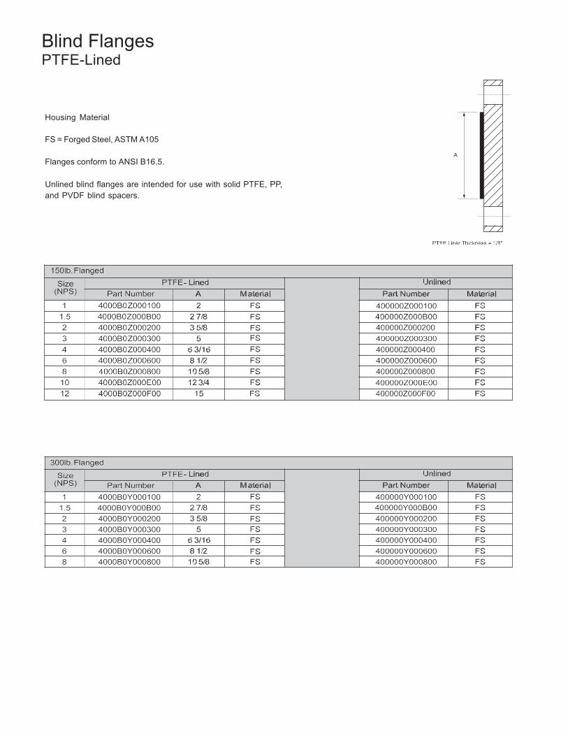
42
Blind Flanges PTFE-Lined
Housing Material
FS = Forged Steel, ASTM A105
Flanges conform to ANSI B16.5.
Unlined blind flanges are intended for use with solid PTFE, PP, and PVDF blind spacers.
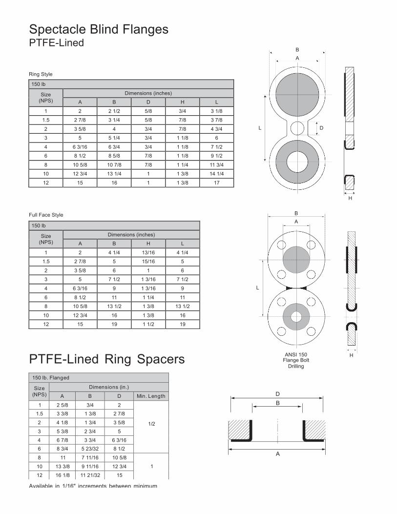
43
150 lb
Size (NPS)
Dimensions (inches)
A B D H L
1 2 2 1/2 5/8 3/4 3 1/8
1.5 2 7/8 3 1/4 5/8 7/8 3 7/8
2 3 5/8 4 3/4 7/8 4 3/4
3 5 5 1/4 3/4 1 1/8 6
4 6 3/16 6 3/4 3/4 1 1/8 7 1/2
6 8 1/2 8 5/8 7/8 1 1/8 9 1/2
8 10 5/8 10 7/8 7/8 1 1/4 11 3/4
10 12 3/4 13 1/4 1 1 3/8 14 1/4
12 15 16 1 1 3/8 17
150 lb
Size (NPS)
Dimensions (inches)
A B H L
1 2 4 1/4 13/16 4 1/4
1.5 2 7/8 5 15/16 5
2 3 5/8 6 1 6
3 5 7 1/2 1 3/16 7 1/2
4 6 3/16 9 1 3/16 9
6 8 1/2 11 1 1/4 11
8 10 5/8 13 1/2 1 3/8 13 1/2
10 12 3/4 16 1 3/8 16
12 15 19 1 1/2 19
150 lb. Flanged
Size (NPS)
Dimensions (in.)
A B D Min. Length
1 2 5/8 3/4 2
1/2
1.5 3 3/8 1 3/8 2 7/8
2 4 1/8 1 3/4 3 5/8
3 5 3/8 2 3/4 5
4 6 7/8 3 3/4 6 3/16
6 8 3/4 5 23/32 8 1/2
8 11 7 11/16 10 5/8
1 10 13 3/8 9 11/16 12 3/4
12 16 1/8 11 21/32 15
Spectacle Blind Flanges PTFE-Lined
B A
Ring Style
L D
H
Full Face Style B A
L
PTFE-Lined Ring Spacers ANSI 150 H Flange Bolt
Drilling
D B
A
Available in 1/16" increments between minimum length and 3.00".
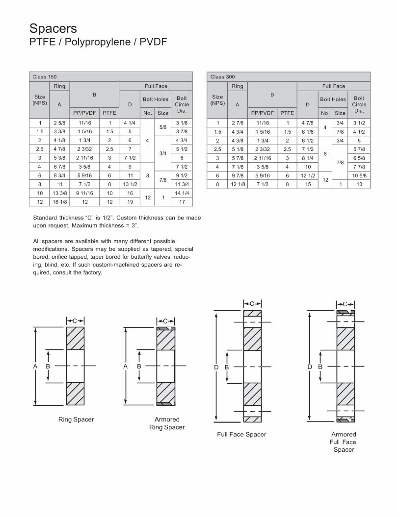
44
Class 300
Size (NPS)
Ring B
Full Face
A
D
Bolt Holes
Bolt
Circle Dia. PP/PVDF PTFE No. Size
1 2 7/8 11/16 1 4 7/8 4
3/4 3 1/2
1.5 4 3/4 1 5/16 1.5 6 1/8 7/8 4 1/2
2 4 3/8 1 3/4 2 6 1/2
8
3/4 5
2.5 5 1/8 2 3/32 2.5 7 1/2
7/8
5 7/8
3 5 7/8 2 11/16 3 8 1/4 6 5/8
4 7 1/8 3 5/8 4 10 7 7/8
6 9 7/8 5 9/16 6 12 1/2 12
10 5/8
8 12 1/8 7 1/2 8 15 1 13
Spacers PTFE / Polypropylene / PVDF
Class 150
Size (NPS)
Ring B
Full Face
A
D
Bolt Holes
Bolt
Circle Dia. PP/PVDF PTFE No. Size
1 2 5/8 11/16 1 4 1/4
4
5/8
3 1/8
1.5 3 3/8 1 5/16 1.5 5 3 7/8
2 4 1/8 1 3/4 2 6
3/4
4 3/4
2.5 4 7/8 2 3/32 2.5 7 5 1/2
3 5 3/8 2 11/16 3 7 1/2 6
4 6 7/8 3 5/8 4 9
8
7 1/2
6 8 3/4 5 9/16 6 11 7/8
9 1/2
8 11 7 1/2 8 13 1/2 11 3/4
10 13 3/8 9 11/16 10 16 12
1
14 1/4
12 16 1/8 12 12 19 17
Standard thickness “C” is 1/2”. Custom thickness can be made upon request. Maximum thickness = 3”.
All spacers are available with many different possible modifications. Spacers may be supplied as tapered, special bored, orifice tapped, taper bored for butterfly valves, reduc- ing, blind, etc. If such custom-machined spacers are re- quired, consult the factory.
C C
C C
A B A B D B D B
Ring Spacer Armored Ring Spacer
Full Face Spacer Armored Full Face
Spacer
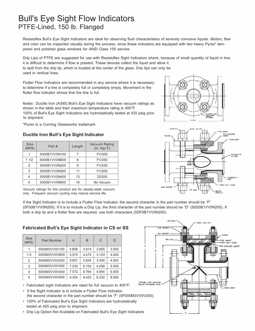
45
Size (NPS)
Part Number
A
B
C
D
1 5000M3VV0V100 4.806 3.914 2.605 3.500
1.5 5000M3VV0VB00 5.575 4.475 3.103 4.000
2 5000M3VV0V200 5.857 4.924 3.490 4.500
3 5000M3VV0V300 7.035 6.102 4.299 5.500
4 5000M3VV0V400 7.572 6.764 4.954 6.500
6 5000M3VV0V600 9.354 8.425 6.330 8.000
Bull's Eye Sight Flow Indicators PTFE-Lined, 150 lb. Flanged
Resistoflex Bull’s Eye Sight Indicators are ideal for observing fluid characteristics of severely corrosive liquids. Motion, flow and color can be inspected visually during the process, since these indicators are equipped with two heavy Pyrex* tem- pered and polished glass windows for ANSI Class 150 service.
Drip Lips of PTFE are suggested for use with Resistoflex Sight Indicators where, because of small quantity of liquid in line, it is difficult to determine if flow is present. These devices collect the liquid and allow it to spill from the drip lip, which is located at the center of the glass. Drip lips can only be used in vertical lines.
Flutter Flow Indicators are recommended in any service where it is necessary to determine if a line is completely full or completely empty. Movement in the flutter flow indicator shows that the line is full.
Notes: Ductile Iron (A395) Bull’s Eye Sight Indicators have vacuum ratings as shown in the table and their maximum temperature rating is 400°F. 100% of Bull’s Eye Sight Indicators are hydrostatically tested at 425 psig prior to shipment.
*Pyrex is a Corning Glassworks trademark.
Ductile Iron Bull’s Eye Sight Indicator
Length
Size
(NPS)
Part #
Length Vacuum Rating
(in. Hg/ F)
1 5000B1VV0N100 7 FV/300
1 1/2 5000B1VV0NB00 8 FV/250
2 5000B1VV0N200 9 FV/250
3 5000B1VV0N300 11 FV/200
4 5000B1VV0N400 13 25/200
6 5000B1VV0N600 16 No Vacuum
Vacuum ratings for this product are for steady-state vacuum, only. Frequent vacuum cycling may reduce service life.
If the Sight Indicator is to include a Flutter Flow Indicator, the second character in the part number should be “F” (5F00B1VV0N200). If it is to include a Drip Lip, the third character of the part number should be “D” (50D0B1VV0N200). If both a drip lip and a flutter flow are required, use both characters (5DF0B1VV0N200).
Fabricated Bull’s Eye Sight Indicator in CS or SS
A
B
C
• Fabricated sight indicators are rated for full vacuum to 400°F. • If the Sight Indicator is to include a Flutter Flow Indicator,
the second character in the part number should be “F” (5F000M3VV0V200). • 100% of Fabricated Bull’s Eye Sight Indicators are hydrostatically
tested at 425 psig prior to shipment. • Drip Lip Option Not Available on Fabricated Bull’s Eye Sight Indicators D
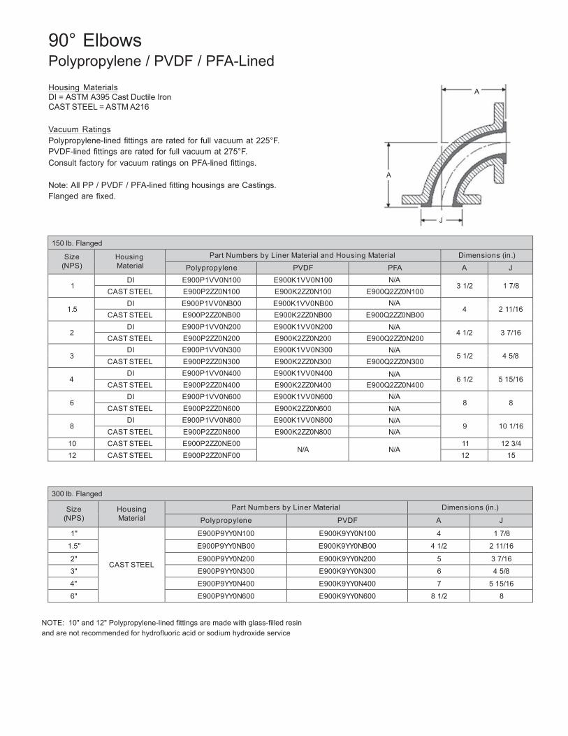
46
90° Elbows Polypropylene / PVDF / PFA-Lined
Housing Materials A DI = ASTM A395 Cast Ductile Iron CAST STEEL = ASTM A216
Vacuum Ratings Polypropylene-lined fittings are rated for full vacuum at 225°F. PVDF-lined fittings are rated for full vacuum at 275°F. Consult factory for vacuum ratings on PFA-lined fittings.
A Note: All PP / PVDF / PFA-lined fitting housings are Castings. Flanged are fixed.
J
150 lb. Flanged
Size (NPS)
Housing Material
Part Numbers by Liner Material and Housing Material Dimensions (in.)
Polypropylene PVDF PFA A J
1 DI E900P1VV0N100 E900K1VV0N100 N/A
3 1/2
1 7/8 CAST STEEL E900P2ZZ0N100 E900K2ZZ0N100 E900Q2ZZ0N100
1.5
DI E900P1VV0NB00 E900K1VV0NB00 N/A 4
2 11/16
CAST STEEL E900P2ZZ0NB00 E900K2ZZ0NB00 E900Q2ZZ0NB00
2 DI E900P1VV0N200 E900K1VV0N200 N/A
4 1/2
3 7/16 CAST STEEL E900P2ZZ0N200 E900K2ZZ0N200 E900Q2ZZ0N200
3
DI E900P1VV0N300 E900K1VV0N300 N/A 5 1/2
4 5/8
CAST STEEL E900P2ZZ0N300 E900K2ZZ0N300 E900Q2ZZ0N300
4 DI E900P1VV0N400 E900K1VV0N400 N/A
6 1/2
5 15/16 CAST STEEL E900P2ZZ0N400 E900K2ZZ0N400 E900Q2ZZ0N400
6
DI E900P1VV0N600 E900K1VV0N600 N/A 8
8
CAST STEEL E900P2ZZ0N600 E900K2ZZ0N600 N/A
8 DI E900P1VV0N800 E900K1VV0N800 N/A
9
10 1/16 CAST STEEL E900P2ZZ0N800 E900K2ZZ0N800 N/A
10 CAST STEEL E900P2ZZ0NE00 N/A
N/A
11 12 3/4 12 CAST STEEL E900P2ZZ0NF00 12 15
300 lb. Flanged
Size (NPS)
Housing Material
Part Numbers by Liner Material Dimensions (in.)
Polypropylene PVDF A J
1"
CAST STEEL
E900P9YY0N100 E900K9YY0N100 4 1 7/8
1.5" E900P9YY0NB00 E900K9YY0NB00 4 1/2 2 11/16
2" E900P9YY0N200 E900K9YY0N200 5 3 7/16
3" E900P9YY0N300 E900K9YY0N300 6 4 5/8
4" E900P9YY0N400 E900K9YY0N400 7 5 15/16
6" E900P9YY0N600 E900K9YY0N600 8 1/2 8
NOTE: 10" and 12" Polypropylene-lined fittings are made with glass-filled resin and are not recommended for hydrofluoric acid or sodium hydroxide service
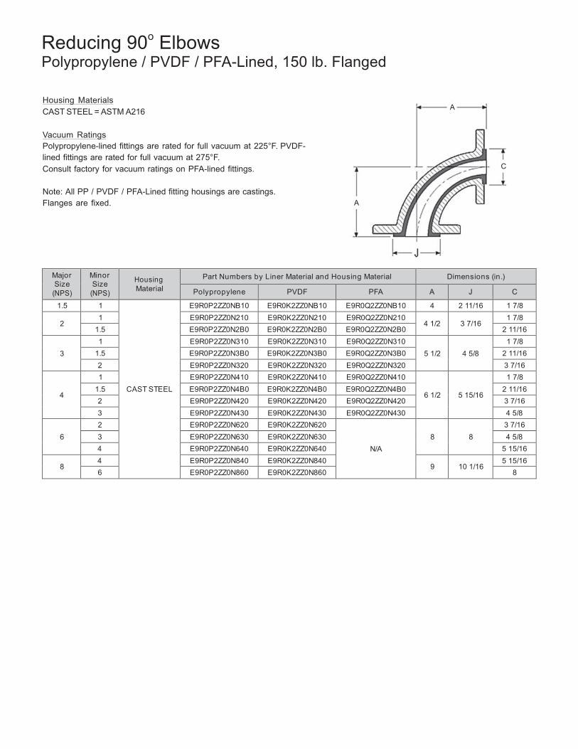
47
Reducing 90o Elbows Polypropylene / PVDF / PFA-Lined, 150 lb. Flanged
Housing Materials CAST STEEL = ASTM A216 A
Vacuum Ratings Polypropylene-lined fittings are rated for full vacuum at 225°F. PVDF-lined fittings are rated for full vacuum at 275°F. Consult factory for vacuum ratings on PFA-lined fittings. C
Note: All PP / PVDF / PFA-Lined fitting housings are castings. Flanges are fixed. A
Major Size
(NPS)
Minor Size
(NPS)
Housing Material
Part Numbers by Liner Material and Housing Material Dimensions (in.)
Polypropylene PVDF PFA A J C
1.5 1
CAST STEEL
E9R0P2ZZ0NB10 E9R0K2ZZ0NB10 E9R0Q2ZZ0NB10 4 2 11/16 1 7/8
2 1 E9R0P2ZZ0N210 E9R0K2ZZ0N210 E9R0Q2ZZ0N210
4 1/2
3 7/16 1 7/8
1.5 E9R0P2ZZ0N2B0 E9R0K2ZZ0N2B0 E9R0Q2ZZ0N2B0 2 11/16
3
1 E9R0P2ZZ0N310 E9R0K2ZZ0N310 E9R0Q2ZZ0N310 5 1/2
4 5/8
1 7/8 1.5 E9R0P2ZZ0N3B0 E9R0K2ZZ0N3B0 E9R0Q2ZZ0N3B0 2 11/16 2 E9R0P2ZZ0N320 E9R0K2ZZ0N320 E9R0Q2ZZ0N320 3 7/16
4
1 E9R0P2ZZ0N410 E9R0K2ZZ0N410 E9R0Q2ZZ0N410
6 1/2
5 15/16
1 7/8 1.5 E9R0P2ZZ0N4B0 E9R0K2ZZ0N4B0 E9R0Q2ZZ0N4B0 2 11/16 2 E9R0P2ZZ0N420 E9R0K2ZZ0N420 E9R0Q2ZZ0N420 3 7/16 3 E9R0P2ZZ0N430 E9R0K2ZZ0N430 E9R0Q2ZZ0N430 4 5/8
6
2 E9R0P2ZZ0N620 E9R0K2ZZ0N620
N/A
8
8
3 7/16 3 E9R0P2ZZ0N630 E9R0K2ZZ0N630 4 5/8 4 E9R0P2ZZ0N640 E9R0K2ZZ0N640 5 15/16
8
4 E9R0P2ZZ0N840 E9R0K2ZZ0N840 9
10 1/16
5 15/16 6 E9R0P2ZZ0N860 E9R0K2ZZ0N860 8
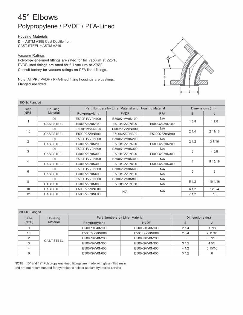
48
45° Elbows Polypropylene / PVDF / PFA-Lined
Housing Materials DI = ASTM A395 Cast Ductile Iron CAST STEEL = ASTM A216
Vacuum Ratings Polypropylene-lined fittings are rated for full vacuum at 225°F. PVDF-lined fittings are rated for full vacuum at 275°F. Consult factory for vacuum ratings on PFA-lined fittings.
Note: All PP / PVDF / PFA-lined fitting housings are castings. B
Flanged are fixed.
J
150 lb. Flanged
Size (NPS)
Housing Material
Part Numbers by Liner Material and Housing Material Dimensions (in.)
Polypropylene PVDF PFA B J
1 DI E500P1VV0N100 E500K1VV0N100 N/A
1 3/4
1 7/8 CAST STEEL E500P2ZZ0N100 E500K2ZZ0N100 E500Q2ZZ0N100
1.5
DI E500P1VV0NB00 E500K1VV0NB00 N/A 2 1/4
2 11/16
CAST STEEL E500P2ZZ0NB00 E500K2ZZ0NB00 E500Q2ZZ0NB00
2 DI E500P1VV0N200 E500K1VV0N200 N/A
2 1/2
3 7/16 CAST STEEL E500P2ZZ0N200 E500K2ZZ0N200 E500Q2ZZ0N200
3
DI E500P1VV0N300 E500K1VV0N300 N/A 3
4 5/8
CAST STEEL E500P2ZZ0N300 E500K2ZZ0N300 E500Q2ZZ0N300
4 DI E500P1VV0N400 E500K1VV0N400 N/A
4
5 15/16 CAST STEEL E500P2ZZ0N400 E500K2ZZ0N400 E500Q2ZZ0N400
6
DI E500P1VV0N600 E500K1VV0N600 N/A 5
8
CAST STEEL E500P2ZZ0N600 E500K2ZZ0N600 N/A
8 DI E500P1VV0N800 E500K1VV0N800 N/A
5 1/2
10 1/16 CAST STEEL E500P2ZZ0N800 E500K2ZZ0N800 N/A
10 CAST STEEL E500P2ZZ0NE00 N/A
N/A 6 1/2 12 3/4
12 CAST STEEL E500P2ZZ0NF00 7 1/2 15
300 lb. Flanged
Size (NPS)
Housing Material
Part Numbers by Liner Material Dimensions (in.)
Polypropylene PVDF B J
1
CAST STEEL
E500P9YY0N100 E500K9YY0N100 2 1/4 1 7/8 1.5 E500P9YY0NB00 E500K9YY0NB00 2 3/4 2 11/16 2 E500P9YY0N200 E500K9YY0N200 3 3 7/16 3 E500P9YY0N300 E500K9YY0N300 3 1/2 4 5/8 4 E500P9YY0N400 E500K9YY0N400 4 1/2 5 15/16 6 E500P9YY0N600 E500K9YY0N600 5 1/2 8
NOTE: 10" and 12" Polypropylene-lined fittings are made with glass-filled resin and are not recommended for hydrofluoric acid or sodium hydroxide service
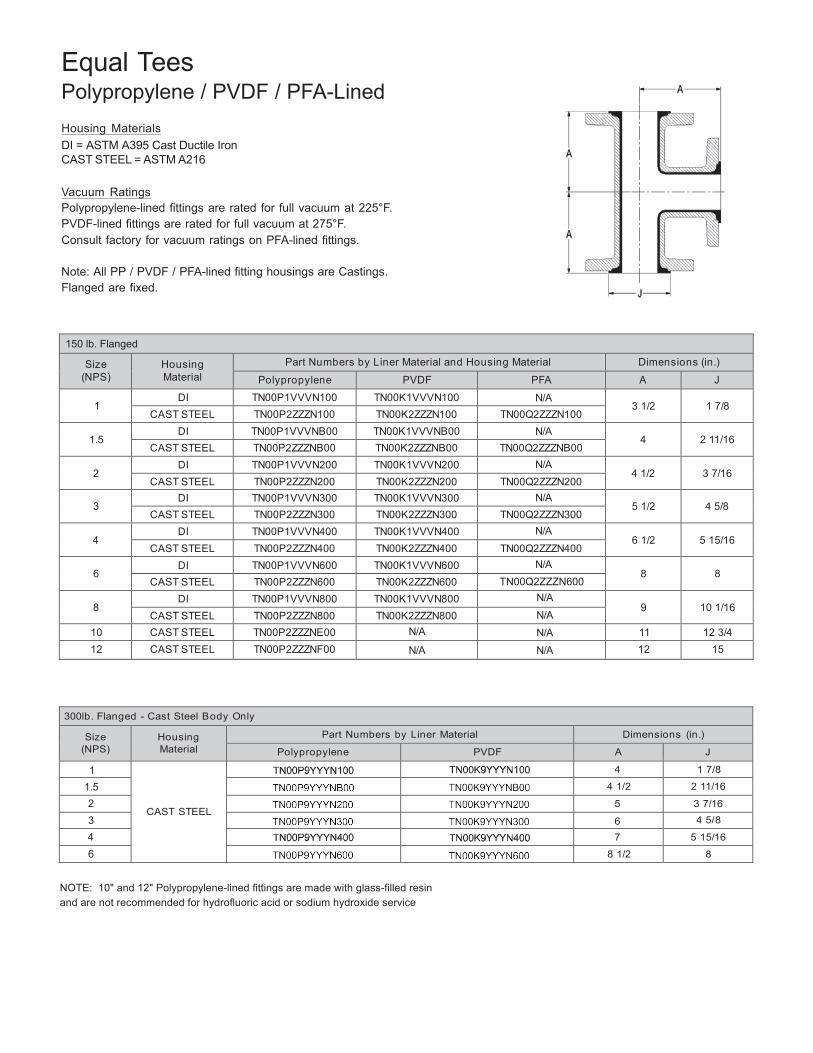
49
Equal Tees Polypropylene / PVDF / PFA-Lined
Housing Materials DI = ASTM A395 Cast Ductile Iron CAST STEEL = ASTM A216
Vacuum Ratings Polypropylene-lined fittings are rated for full vacuum at 225°F. PVDF-lined fittings are rated for full vacuum at 275°F. Consult factory for vacuum ratings on PFA-lined fittings.
Note: All PP / PVDF / PFA-lined fitting housings are Castings. Flanged are fixed.
150 lb. Flanged
Size (NPS)
Housing Material
Part Numbers by Liner Material and Housing Material Dimensions (in.)
Polypropylene PVDF PFA A J
1 DI TN00P1VVVN100 TN00K1VVVN100 N/A
3 1/2
1 7/8 CAST STEEL TN00P2ZZZN100 TN00K2ZZZN100 TN00Q2ZZZN100
1.5
DI TN00P1VVVNB00 TN00K1VVVNB00 N/A 4
2 11/16
CAST STEEL TN00P2ZZZNB00 TN00K2ZZZNB00 TN00Q2ZZZNB00
2 DI TN00P1VVVN200 TN00K1VVVN200 N/A
4 1/2
3 7/16 CAST STEEL TN00P2ZZZN200 TN00K2ZZZN200 TN00Q2ZZZN200
3
DI TN00P1VVVN300 TN00K1VVVN300 N/A 5 1/2
4 5/8
CAST STEEL TN00P2ZZZN300 TN00K2ZZZN300 TN00Q2ZZZN300
4 DI TN00P1VVVN400 TN00K1VVVN400 N/A
6 1/2
5 15/16 CAST STEEL TN00P2ZZZN400 TN00K2ZZZN400 TN00Q2ZZZN400
6
DI TN00P1VVVN600 TN00K1VVVN600 N/A 8
8
CAST STEEL TN00P2ZZZN600 TN00K2ZZZN600 TN00Q2ZZZN600
8 DI TN00P1VVVN800 TN00K1VVVN800 N/A
9
10 1/16 CAST STEEL TN00P2ZZZN800 TN00K2ZZZN800 N/A
10 CAST STEEL TN00P2ZZZNE00 N/A N/A 11 12 3/4 12 CAST STEEL TN00P2ZZZNF00 N/A N/A 12 15
300lb. Flanged - Cast Steel B ody Only
Size (NPS)
Housing Material
Part Numbers by Liner Material Dimensions (in.)
Polypropylene PVDF A J
1
CAST STEEL
4 1 7/8
1.5 4 1/2 2 11/16
2 5 3 7/16
3 6 4 5/8
4 7 5 15/16
6 8 1/2 8
NOTE: 10" and 12" Polypropylene-lined fittings are made with glass-filled resin and are not recommended for hydrofluoric acid or sodium hydroxide service
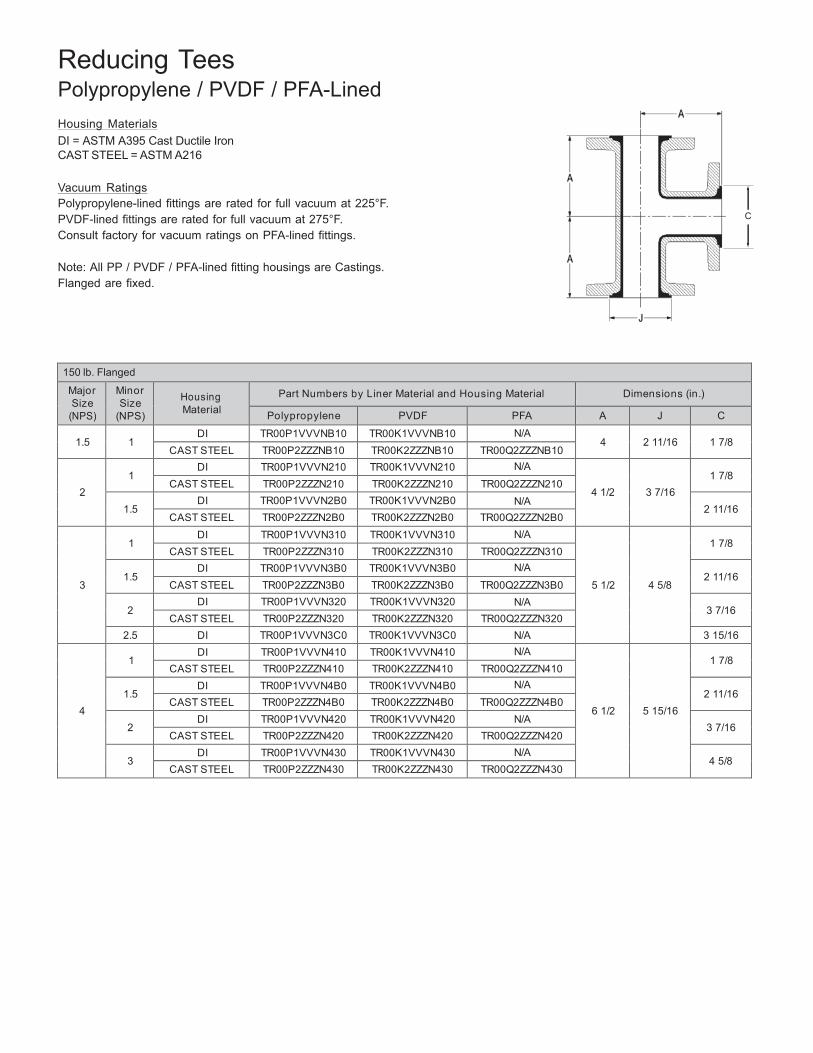
50
Reducing Tees Polypropylene / PVDF / PFA-Lined
Housing Materials DI = ASTM A395 Cast Ductile Iron CAST STEEL = ASTM A216
Vacuum Ratings Polypropylene-lined fittings are rated for full vacuum at 225°F. PVDF-lined fittings are rated for full vacuum at 275°F. C
Consult factory for vacuum ratings on PFA-lined fittings.
Note: All PP / PVDF / PFA-lined fitting housings are Castings. Flanged are fixed.
150 lb. Flanged
Major Size
(NPS)
Minor Size
(NPS)
Housing Material
Part Numbers by Liner Material and Housing Material Dimensions (in.)
Polypropylene PVDF PFA A J C
1.5
1 DI TR00P1VVVNB10 TR00K1VVVNB10 N/A
4
2 11/16
1 7/8 CAST STEEL TR00P2ZZZNB10 TR00K2ZZZNB10 TR00Q2ZZZNB10
2
1
DI TR00P1VVVN210 TR00K1VVVN210 N/A
4 1/2
3 7/16
1 7/8
CAST STEEL TR00P2ZZZN210 TR00K2ZZZN210 TR00Q2ZZZN210
1.5 DI TR00P1VVVN2B0 TR00K1VVVN2B0 N/A
2 11/16 CAST STEEL TR00P2ZZZN2B0 TR00K2ZZZN2B0 TR00Q2ZZZN2B0
3
1
DI TR00P1VVVN310 TR00K1VVVN310 N/A
5 1/2
4 5/8
1 7/8
CAST STEEL TR00P2ZZZN310 TR00K2ZZZN310 TR00Q2ZZZN310
1.5 DI TR00P1VVVN3B0 TR00K1VVVN3B0 N/A
2 11/16 CAST STEEL TR00P2ZZZN3B0 TR00K2ZZZN3B0 TR00Q2ZZZN3B0
2
DI TR00P1VVVN320 TR00K1VVVN320 N/A 3 7/16
CAST STEEL TR00P2ZZZN320 TR00K2ZZZN320 TR00Q2ZZZN320 2.5 DI TR00P1VVVN3C0 TR00K1VVVN3C0 N/A 3 15/16
4
1
DI TR00P1VVVN410 TR00K1VVVN410 N/A
6 1/2
5 15/16
1 7/8
CAST STEEL TR00P2ZZZN410 TR00K2ZZZN410 TR00Q2ZZZN410
1.5 DI TR00P1VVVN4B0 TR00K1VVVN4B0 N/A
2 11/16 CAST STEEL TR00P2ZZZN4B0 TR00K2ZZZN4B0 TR00Q2ZZZN4B0
2
DI TR00P1VVVN420 TR00K1VVVN420 N/A 3 7/16
CAST STEEL TR00P2ZZZN420 TR00K2ZZZN420 TR00Q2ZZZN420
3 DI TR00P1VVVN430 TR00K1VVVN430 N/A
4 5/8 CAST STEEL TR00P2ZZZN430 TR00K2ZZZN430 TR00Q2ZZZN430
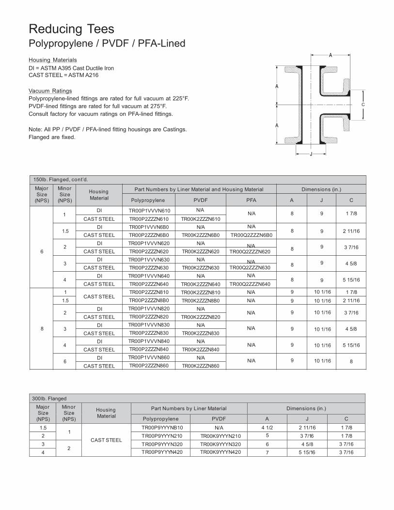
51
Reducing Tees Polypropylene / PVDF / PFA-Lined
Housing Materials DI = ASTM A395 Cast Ductile Iron CAST STEEL = ASTM A216
Vacuum Ratings Polypropylene-lined fittings are rated for full vacuum at 225°F. PVDF-lined fittings are rated for full vacuum at 275°F. C
Consult factory for vacuum ratings on PFA-lined fittings.
Note: All PP / PVDF / PFA-lined fitting housings are Castings. Flanged are fixed.
150lb. Flanged, cont’d.
Major Size
Minor Size
Housing
Part Numbers by Liner Material and Housing Material
Dimensions (in.)
(NPS) (NPS) Material Polypropylene PVDF PFA A J C
DI TR00P1VVVN610 1
N/A N/A
8 9 1 7/8
1.5
2 6
3
4
1 1.5
2
8 3
4
6
CAST STEEL DI
CAST STEEL DI
CAST STEEL DI
CAST STEEL DI
CAST STEEL
CAST STEEL
DI CAST STEEL
DI CAST STEEL
DI CAST STEEL
DI CAST STEEL
TR00P2ZZZN610 TR00P1VVVN6B0 TR00P2ZZZN6B0 TR00P1VVVN620 TR00P2ZZZN620 TR00P1VVVN630 TR00P2ZZZN630 TR00P1VVVN640 TR00P2ZZZN640 TR00P2ZZZN810 TR00P2ZZZN8B0 TR00P1VVVN820 TR00P2ZZZN820 TR00P1VVVN830 TR00P2ZZZN830 TR00P1VVVN840 TR00P2ZZZN840 TR00P1VVVN860 TR00P2ZZZN860
TR00K2ZZZN610 N/A
TR00K2ZZZN6B0 N/A
TR00K2ZZZN620 N/A
TR00K2ZZZN630 N/A
TR00K2ZZZN640 TR00K2ZZZN810 TR00K2ZZZN8B0
N/A TR00K2ZZZN820
N/A TR00K2ZZZN830
N/A TR00K2ZZZN840
N/A TR00K2ZZZN860
N/A
8 TR00Q2ZZZN6B0
N/A 8 TR00Q2ZZZN620
N/A 8 TR00Q2ZZZN630
N/A 8
TR00Q2ZZZN640 N/A 9 N/A 9
N/A 9
N/A 9
N/A 9
N/A 9
9
9
9
9
10 1/16
10 1/16
10 1/16
10 1/16
10 1/16
10 1/16
2 11/16
3 7/16
4 5/8
5 15/16
1 7/8 2 11/16
3 7/16
4 5/8
5 15/16
8
300 lb. Flanged Major Size
(NPS)
Minor Size
(NPS)
Housing Material
Part Numbers by Liner Material Dimensions (in.)
Polypropylene PVDF A J C
1.5 1
CAST STEEL
TR00P9YYYNB10 N/A 4 1/2 2 11/16 1 7/8 2 TR00P9YYYN210 TR00K9YYYN210 5 3 7/16 1 7/8 3
2 TR00P9YYYN320 TR00K9YYYN320 6 4 5/8 3 7/16
4 TR00P9YYYN420 TR00K9YYYN420 7 5 15/16 3 7/16
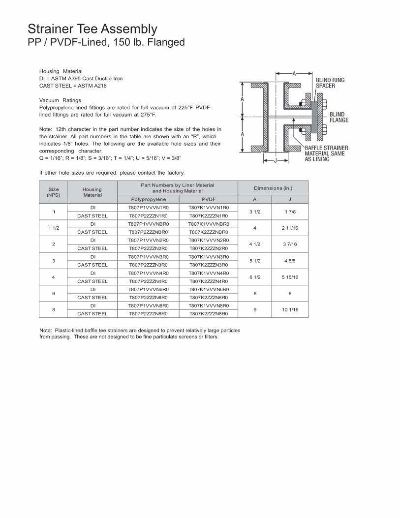
52
Strainer Tee Assembly PP / PVDF-Lined, 150 lb. Flanged
Housing Material DI = ASTM A395 Cast Ductile Iron CAST STEEL = ASTM A216
Vacuum Ratings Polypropylene-lined fittings are rated for full vacuum at 225°F. PVDF-lined fittings are rated for full vacuum at 275°F.
Note: 12th character in the part number indicates the size of the holes in the strainer. All part numbers in the table are shown with an “R”, which indicates 1/8” holes. The following are the available hole sizes and their corresponding character: Q = 1/16”; R = 1/8”; S = 3/16”; T = 1/4”; U = 5/16”; V = 3/8”
If other hole sizes are required, please contact the factory.
Size (NPS)
Housing Material
Part Numbers by Liner Material and Housing Material
Dimensions (in.)
Polypropylene PVDF A J
1 DI T807P1VVVN1R0 T807K1VVVN1R0
3 1/2
1 7/8 CAST STEEL T807P2ZZZN1R0 T807K2ZZZN1R0
1 1/2
DI T807P1VVVNBR0 T807K1VVVNBR0 4
2 11/16
CAST STEEL T807P2ZZZNBR0 T807K2ZZZNBR0
2 DI T807P1VVVN2R0 T807K1VVVN2R0
4 1/2
3 7/16 CAST STEEL T807P2ZZZN2R0 T807K2ZZZN2R0
3
DI T807P1VVVN3R0 T807K1VVVN3R0 5 1/2
4 5/8
CAST STEEL T807P2ZZZN3R0 T807K2ZZZN3R0
4 DI T807P1VVVN4R0 T807K1VVVN4R0
6 1/2
5 15/16 CAST STEEL T807P2ZZZN4R0 T807K2ZZZN4R0
6
DI T807P1VVVN6R0 T807K1VVVN6R0 8
8
CAST STEEL T807P2ZZZN6R0 T807K2ZZZN6R0
8 DI T807P1VVVN8R0 T807K1VVVN8R0
9
10 1/16 CAST STEEL T807P2ZZZN8R0 T807K2ZZZN8R0
Note: Plastic-lined baffle tee strainers are designed to prevent relatively large particles from passing. These are not designed to be fine particulate screens or filters.
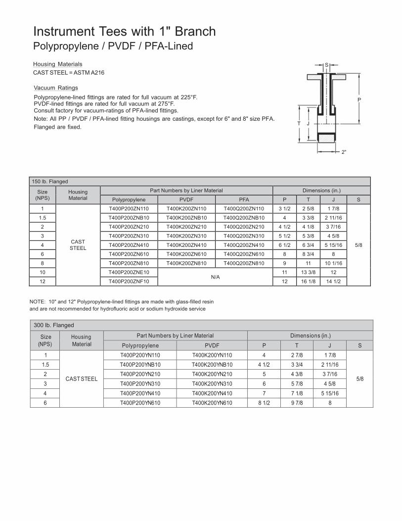
53
Instrument Tees with 1" Branch Polypropylene / PVDF / PFA-Lined
Housing Materials S CAST STEEL = ASTM A216
Vacuum Ratings Polypropylene-lined fittings are rated for full vacuum at 225°F. P PVDF-lined fittings are rated for full vacuum at 275°F. Consult factory for vacuum-ratings of PFA-lined fittings. Note: All PP / PVDF / PFA-lined fitting housings are castings, except for 6" and 8" size PFA. Flanged are fixed. T J
2"
150 lb. Flanged
Size (NPS)
Housing Material
Part Numbers by Liner Material Dimensions (in.)
Polypropylene PVDF PFA P T J S
1
CAST STEEL
T400P200ZN110 T400K200ZN110 T400Q200ZN110 3 1/2 2 5/8 1 7/8
5/8
1.5 T400P200ZNB10 T400K200ZNB10 T400Q200ZNB10 4 3 3/8 2 11/16
2 T400P200ZN210 T400K200ZN210 T400Q200ZN210 4 1/2 4 1/8 3 7/16
3 T400P200ZN310 T400K200ZN310 T400Q200ZN310 5 1/2 5 3/8 4 5/8
4 T400P200ZN410 T400K200ZN410 T400Q200ZN410 6 1/2 6 3/4 5 15/16
6 T400P200ZN610 T400K200ZN610 T400Q200ZN610 8 8 3/4 8
8 T400P200ZN810 T400K200ZN810 T400Q200ZN810 9 11 10 1/16
10 T400P200ZNE10 N/A
11 13 3/8 12
12 T400P200ZNF10 12 16 1/8 14 1/2
NOTE: 10" and 12" Polypropylene-lined fittings are made with glass-filled resin and are not recommended for hydrofluoric acid or sodium hydroxide service
300 lb. Flanged
Size (NPS)
Housing Material
Part Numbers by Liner Material Dimensions (in.)
Polypropylene PVDF P T J S 1
CAST STEEL
T400P200YN110 T400K200YN110 4 2 7/8 1 7/8
5/8
1.5 T400P200YNB10 T400K200YNB10 4 1/2 3 3/4 2 11/16 2 T400P200YN210 T400K200YN210 5 4 3/8 3 7/16 3 T400P200YN310 T400K200YN310 6 5 7/8 4 5/8 4 T400P200YN410 T400K200YN410 7 7 1/8 5 15/16 6 T400P200YN610 T400K200YN610 8 1/2 9 7/8 8
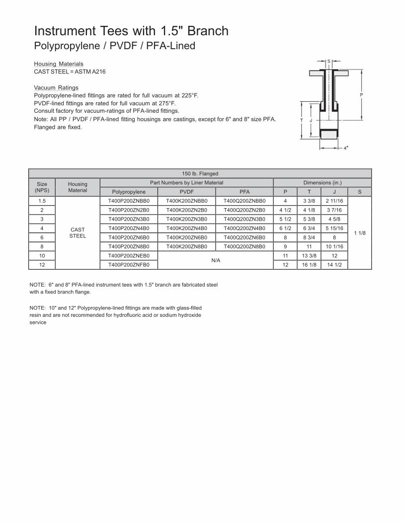
54
Instrument Tees with 1.5" Branch Polypropylene / PVDF / PFA-Lined
Housing Materials CAST STEEL = ASTM A216
Vacuum Ratings Polypropylene-lined fittings are rated for full vacuum at 225°F. PVDF-lined fittings are rated for full vacuum at 275°F. Consult factory for vacuum-ratings of PFA-lined fittings. Note: All PP / PVDF / PFA-lined fitting housings are castings, except for 6" and 8" size PFA. Flanged are fixed.
150 lb. Flanged
Size (NPS)
Housing Material
Part Numbers by Liner Material Dimensions (in.)
Polypropylene PVDF PFA P T J S
1.5
CAST STEEL
T400P200ZNBB0 T400K200ZNBB0 T400Q200ZNBB0 4 3 3/8 2 11/16
1 1/8
2 T400P200ZN2B0 T400K200ZN2B0 T400Q200ZN2B0 4 1/2 4 1/8 3 7/16
3 T400P200ZN3B0 T400K200ZN3B0 T400Q200ZN3B0 5 1/2 5 3/8 4 5/8
4 T400P200ZN4B0 T400K200ZN4B0 T400Q200ZN4B0 6 1/2 6 3/4 5 15/16
6 T400P200ZN6B0 T400K200ZN6B0 T400Q200ZN6B0 8 8 3/4 8
8 T400P200ZN8B0 T400K200ZN8B0 T400Q200ZN8B0 9 11 10 1/16
10 T400P200ZNEB0 N/A
11 13 3/8 12
12 T400P200ZNFB0 12 16 1/8 14 1/2
NOTE: 6" and 8" PFA-lined instrument tees with 1.5" branch are fabricated steel with a fixed branch flange.
NOTE: 10" and 12" Polypropylene-lined fittings are made with glass-filled resin and are not recommended for hydrofluoric acid or sodium hydroxide service
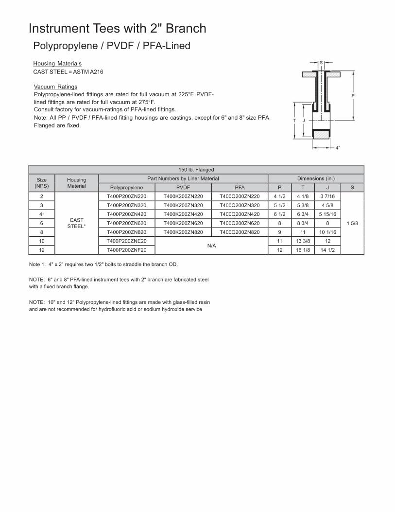
55
Instrument Tees with 2" Branch
Polypropylene / PVDF / PFA-Lined
Housing Materials CAST STEEL = ASTM A216
Vacuum Ratings Polypropylene-lined fittings are rated for full vacuum at 225°F. PVDF-lined fittings are rated for full vacuum at 275°F. Consult factory for vacuum-ratings of PFA-lined fittings. Note: All PP / PVDF / PFA-lined fitting housings are castings, except for 6" and 8" size PFA. Flanged are fixed.
150 lb. Flanged
Size (NPS)
Housing Material
Part Numbers by Liner Material Dimensions (in.)
Polypropylene PVDF PFA P T J S
2
CAST STEEL*
T400P200ZN220 T400K200ZN220 T400Q200ZN220 4 1/2 4 1/8 3 7/16
1 5/8
3 T400P200ZN320 T400K200ZN320 T400Q200ZN320 5 1/2 5 3/8 4 5/8
41 T400P200ZN420 T400K200ZN420 T400Q200ZN420 6 1/2 6 3/4 5 15/16
6 T400P200ZN620 T400K200ZN620 T400Q200ZN620 8 8 3/4 8
8 T400P200ZN820 T400K200ZN820 T400Q200ZN820 9 11 10 1/16
10 T400P200ZNE20 N/A
11 13 3/8 12
12 T400P200ZNF20 12 16 1/8 14 1/2
Note 1: 4" x 2" requires two 1/2" bolts to straddle the branch OD.
NOTE: 6" and 8" PFA-lined instrument tees with 2" branch are fabricated steel with a fixed branch flange.
NOTE: 10" and 12" Polypropylene-lined fittings are made with glass-filled resin and are not recommended for hydrofluoric acid or sodium hydroxide service
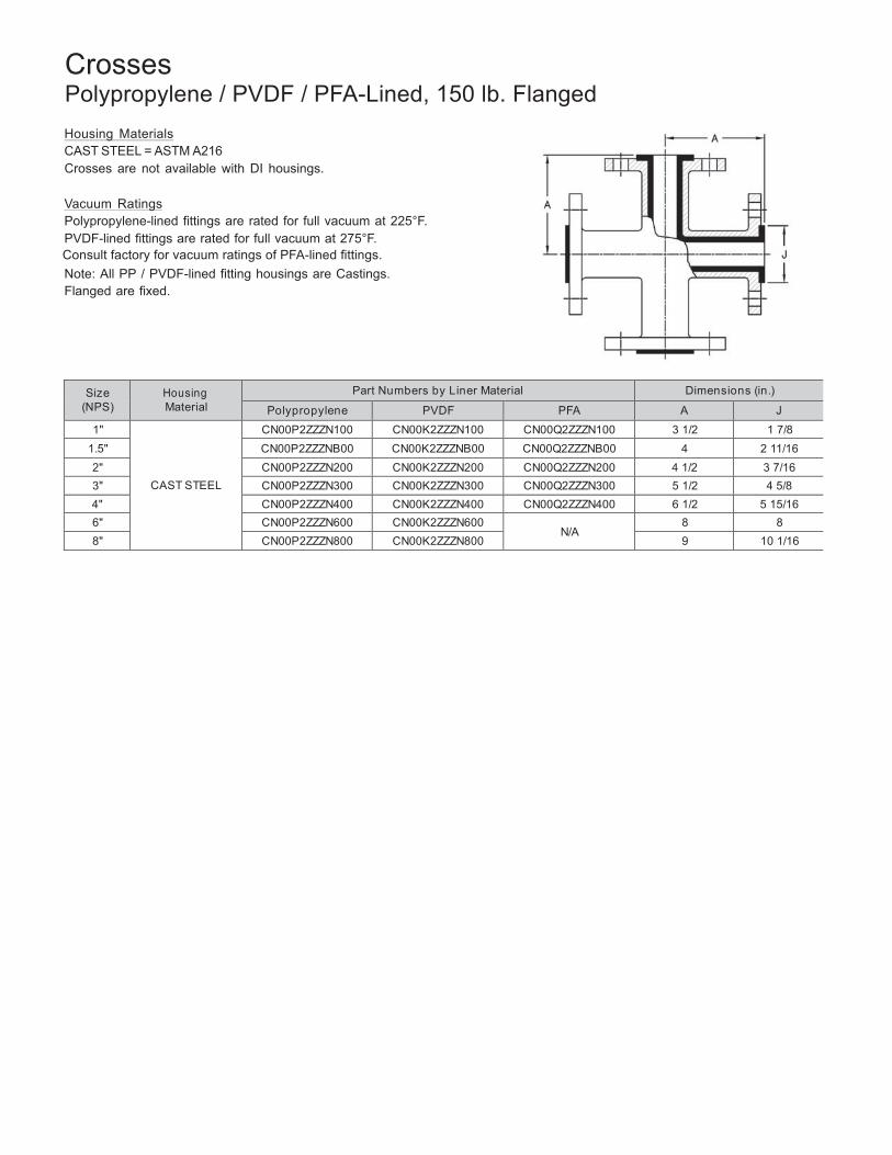
56
Crosses Polypropylene / PVDF / PFA-Lined, 150 lb. Flanged
Housing Materials CAST STEEL = ASTM A216 Crosses are not available with DI housings.
Vacuum Ratings Polypropylene-lined fittings are rated for full vacuum at 225°F. PVDF-lined fittings are rated for full vacuum at 275°F. Consult factory for vacuum ratings of PFA-lined fittings. Note: All PP / PVDF-lined fitting housings are Castings. Flanged are fixed.
Size (NPS)
Housing Material
Part Numbers by Liner Material Dimensions (in.)
Polypropylene PVDF PFA A J
1"
CAST STEEL
CN00P2ZZZN100 CN00K2ZZZN100 CN00Q2ZZZN100 3 1/2 1 7/8 1.5" CN00P2ZZZNB00 CN00K2ZZZNB00 CN00Q2ZZZNB00 4 2 11/16 2" CN00P2ZZZN200 CN00K2ZZZN200 CN00Q2ZZZN200 4 1/2 3 7/16 3" CN00P2ZZZN300 CN00K2ZZZN300 CN00Q2ZZZN300 5 1/2 4 5/8 4" CN00P2ZZZN400 CN00K2ZZZN400 CN00Q2ZZZN400 6 1/2 5 15/16 6" CN00P2ZZZN600 CN00K2ZZZN600
N/A 8 8
8" CN00P2ZZZN800 CN00K2ZZZN800 9 10 1/16
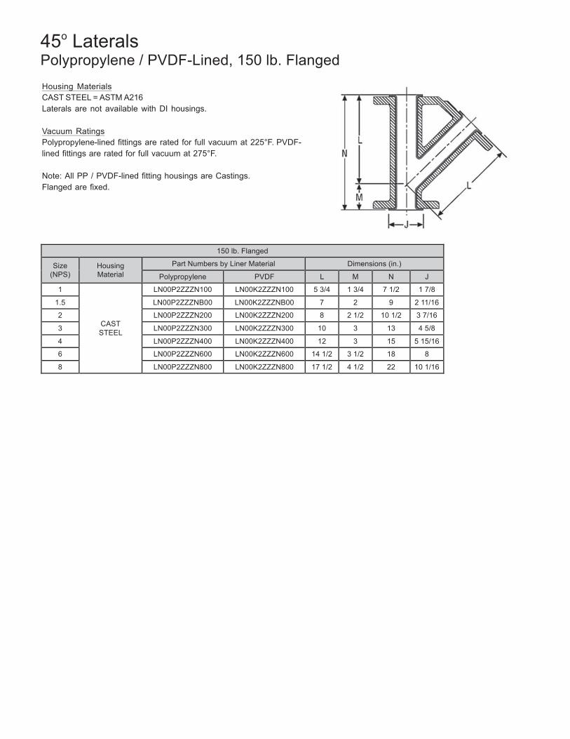
57
45o Laterals Polypropylene / PVDF-Lined, 150 lb. Flanged
Housing Materials CAST STEEL = ASTM A216 Laterals are not available with DI housings.
Vacuum Ratings Polypropylene-lined fittings are rated for full vacuum at 225°F. PVDF-lined fittings are rated for full vacuum at 275°F.
Note: All PP / PVDF-lined fitting housings are Castings. Flanged are fixed.
150 lb. Flanged
Size (NPS)
Housing Material
Part Numbers by Liner Material Dimensions (in.)
Polypropylene PVDF L M N J
1
CAST STEEL
LN00P2ZZZN100 LN00K2ZZZN100 5 3/4 1 3/4 7 1/2 1 7/8
1.5 LN00P2ZZZNB00 LN00K2ZZZNB00 7 2 9 2 11/16
2 LN00P2ZZZN200 LN00K2ZZZN200 8 2 1/2 10 1/2 3 7/16
3 LN00P2ZZZN300 LN00K2ZZZN300 10 3 13 4 5/8
4 LN00P2ZZZN400 LN00K2ZZZN400 12 3 15 5 15/16
6 LN00P2ZZZN600 LN00K2ZZZN600 14 1/2 3 1/2 18 8
8 LN00P2ZZZN800 LN00K2ZZZN800 17 1/2 4 1/2 22 10 1/16
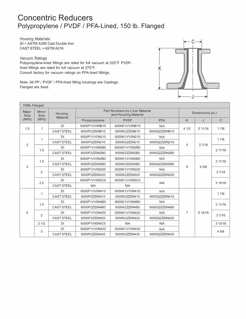
58
Concentric Reducers Polypropylene / PVDF / PFA-Lined, 150 lb. Flanged
Housing Materials DI = ASTM A395 Cast Ductile Iron CAST STEEL = ASTM A216
Vacuum Ratings Polypropylene-lined fittings are rated for full vacuum at 225°F. PVDF-lined fittings are rated for full vacuum at 275°F. Consult factory for vacuum ratings on PFA-lined fittings.
Note: All PP / PVDF / PFA-lined fitting housings are Castings. Flanged are fixed.
150lb. Flanged
Major Size
(NPS)
Minor Size
(NPS)
Housing Material
Part Numbers by Liner Material and Housing Material
Dimensions (in.)
Polypropylene PVDF PFA K J C
1.5
1 DI 6000P1VV0NB10 6000K1VV0NB10 N/A
4 1/2
2 11/16
1 7/8 CAST STEEL 6000P2ZZ0NB10 6000K2ZZ0NB10 6000Q2ZZ0NB10
2
1
DI 6000P1VV0N210 6000K1VV0N210 N/A
5
3 7/16
1 7/8
CAST STEEL 6000P2ZZ0N210 6000K2ZZ0N210 6000Q2ZZ0N210
1.5 DI 6000P1VV0N2B0 6000K1VV0N2B0 N/A
2 11/16 CAST STEEL 6000P2ZZ0N2B0 6000K2ZZ0N2B0 6000Q2ZZ0N2B0
3
1.5
DI 6000P1VV0N3B0 6000K1VV0N3B0 N/A
6
4 5/8
2 11/16
CAST STEEL 6000P2ZZ0N3B0 6000K2ZZ0N3B0 6000Q2ZZ0N3B0
2 DI 6000P1VV0N320 6000K1VV0N320 N/A
3 7/16 CAST STEEL 6000P2ZZ0N320 6000K2ZZ0N320 6000Q2ZZ0N320
2.5
DI 6000P1VV0N3C0 6000K1VV0N3C0 N/A
3 15/16
CAST STEEL N/A N/A
4
1
DI 6000P1VV0N410 6000K1VV0N410 N/A
7
5 15/16
1 7/8
CAST STEEL 6000P2ZZ0N410 6000K2ZZ0N410 6000Q2ZZ0N410
1.5 DI 6000P1VV0N4B0 6000K1VV0N4B0 N/A
2 11/16 CAST STEEL 6000P2ZZ0N4B0 6000K2ZZ0N4B0 6000Q2ZZ0N4B0
2
DI 6000P1VV0N420 6000K1VV0N420 N/A 3 7/16
CAST STEEL 6000P2ZZ0N420 6000K2ZZ0N420 6000Q2ZZ0N420
2 1/2 DI 6000P1VV0N4C0 N/A N/A 3 15/16
3 DI 6000P1VV0N430 6000K1VV0N430 N/A
4 5/8 CAST STEEL 6000P2ZZ0N430 6000K2ZZ0N430 6000Q2ZZ0N430
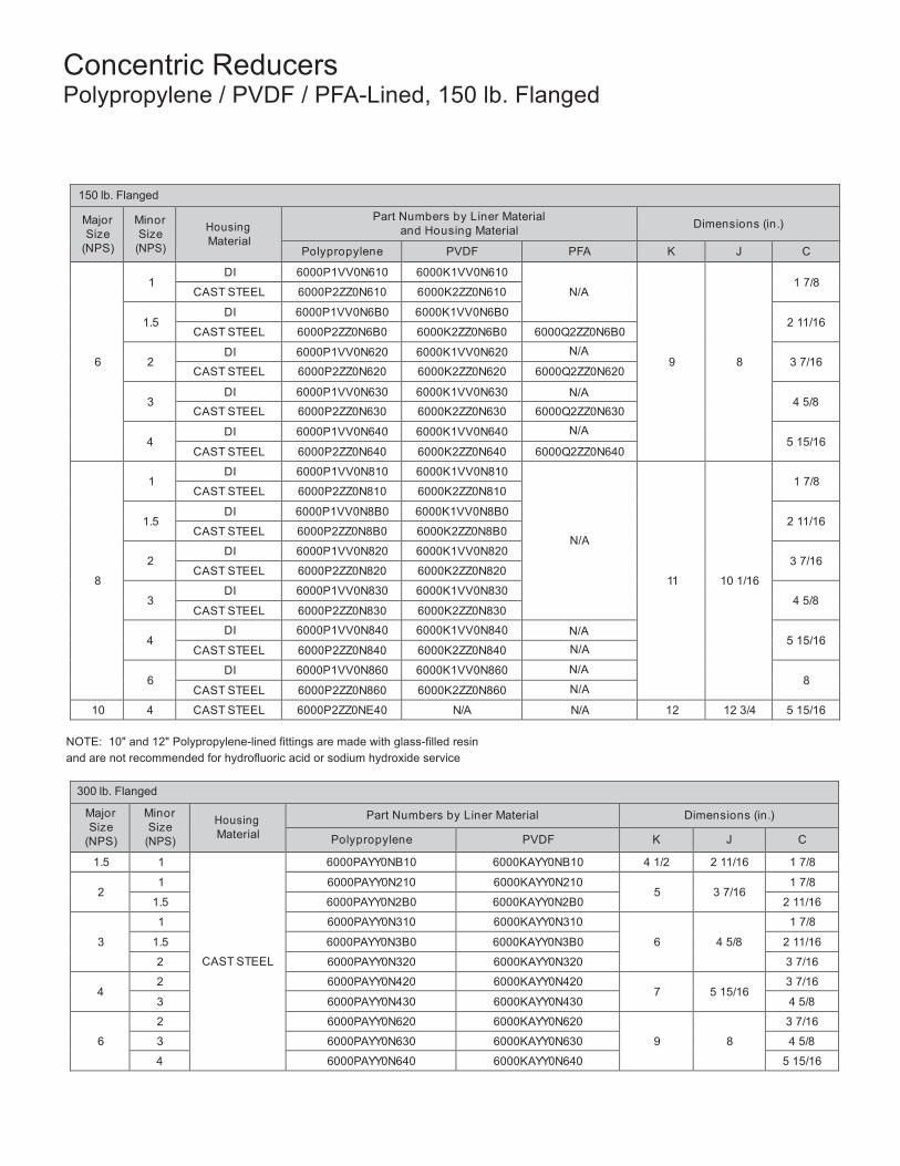
59
Concentric Reducers Polypropylene / PVDF / PFA-Lined, 150 lb. Flanged
150 lb. Flanged
Major Size
(NPS)
Minor Size
(NPS)
Housing Material
Part Numbers by Liner Material and Housing Material
Dimensions (in.)
Polypropylene PVDF PFA K J C
6
1
DI 6000P1VV0N610 6000K1VV0N610
N/A
9
8
1 7/8
CAST STEEL 6000P2ZZ0N610 6000K2ZZ0N610
1.5 DI 6000P1VV0N6B0 6000K1VV0N6B0
2 11/16 CAST STEEL 6000P2ZZ0N6B0 6000K2ZZ0N6B0 6000Q2ZZ0N6B0
2
DI 6000P1VV0N620 6000K1VV0N620 N/A 3 7/16
CAST STEEL 6000P2ZZ0N620 6000K2ZZ0N620 6000Q2ZZ0N620
3 DI 6000P1VV0N630 6000K1VV0N630 N/A
4 5/8 CAST STEEL 6000P2ZZ0N630 6000K2ZZ0N630 6000Q2ZZ0N630
4
DI 6000P1VV0N640 6000K1VV0N640 N/A 5 15/16
CAST STEEL 6000P2ZZ0N640 6000K2ZZ0N640 6000Q2ZZ0N640
8
1
DI 6000P1VV0N810 6000K1VV0N810
N/A
11
10 1/16
1 7/8
CAST STEEL 6000P2ZZ0N810 6000K2ZZ0N810
1.5 DI 6000P1VV0N8B0 6000K1VV0N8B0
2 11/16 CAST STEEL 6000P2ZZ0N8B0 6000K2ZZ0N8B0
2
DI 6000P1VV0N820 6000K1VV0N820 3 7/16
CAST STEEL 6000P2ZZ0N820 6000K2ZZ0N820
3 DI 6000P1VV0N830 6000K1VV0N830
4 5/8 CAST STEEL 6000P2ZZ0N830 6000K2ZZ0N830
4
DI 6000P1VV0N840 6000K1VV0N840 N/A 5 15/16
CAST STEEL 6000P2ZZ0N840 6000K2ZZ0N840 N/A
6 DI 6000P1VV0N860 6000K1VV0N860 N/A
8 CAST STEEL 6000P2ZZ0N860 6000K2ZZ0N860 N/A
10 4 CAST STEEL 6000P2ZZ0NE40 N/A N/A 12 12 3/4 5 15/16
NOTE: 10" and 12" Polypropylene-lined fittings are made with glass-filled resin and are not recommended for hydrofluoric acid or sodium hydroxide service
300 lb. Flanged
Major Size
(NPS)
Minor Size
(NPS)
Housing Material
Part Numbers by Liner Material Dimensions (in.)
Polypropylene PVDF K J C
1.5 1
CAST STEEL
6000PAYY0NB10 6000KAYY0NB10 4 1/2 2 11/16 1 7/8
2 1 6000PAYY0N210 6000KAYY0N210
5
3 7/16 1 7/8
1.5 6000PAYY0N2B0 6000KAYY0N2B0 2 11/16
3
1 6000PAYY0N310 6000KAYY0N310
6
4 5/8
1 7/8
1.5 6000PAYY0N3B0 6000KAYY0N3B0 2 11/16
2 6000PAYY0N320 6000KAYY0N320 3 7/16
4 2 6000PAYY0N420 6000KAYY0N420
7
5 15/16 3 7/16
3 6000PAYY0N430 6000KAYY0N430 4 5/8
6
2 6000PAYY0N620 6000KAYY0N620
9
8
3 7/16
3 6000PAYY0N630 6000KAYY0N630 4 5/8
4 6000PAYY0N640 6000KAYY0N640 5 15/16
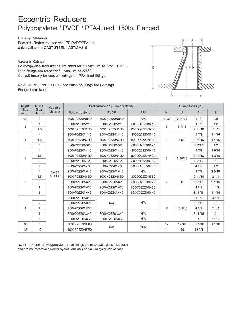
60
Eccentric Reducers Polypropylene / PVDF / PFA-Lined, 150lb. Flanged
Housing Materials Eccentric Reducers lined with PP/PVDF/PFA are only available in CAST STEEL = ASTM A216
Vacuum Ratings Polypropylene-lined fittings are rated for full vacuum at 225°F. PVDF-lined fittings are rated for full vacuum at 275°F. Consult factory for vacuum ratings on PFA-lined fittings.
Note: All PP / PVDF / PFA-lined fitting housings are Castings. Flanged are fixed.
Major Size
(NPS)
Minor Size
(NPS)
Housing Material
Part Number by Liner Material Dimensions (in.)
Polypropylene PVDF PFA K J C E
1.5 1
CAST STEEL*
8000P2ZZ0NB10 8000K2ZZ0NB10 N/A 4 1/2 2 11/16 1 7/8 3/8
2 1 8000P2ZZ0N210 8000K2ZZ0N210 8000Q2ZZ0N210
5
3 7/16 1 7/8 1/2
1.5 8000P2ZZ0N2B0 8000K2ZZ0N2B0 8000Q2ZZ0N2B0 2 11/16 3/16
3
1 8000P2ZZ0N310 8000K2ZZ0N310 8000Q2ZZ0N310
6
4 5/8
1 7/8 1 1/16
1.5 8000P2ZZ0N3B0 8000K2ZZ0N3B0 8000Q2ZZ0N3B0 2 11/16 1 1/16
2 8000P2ZZ0N320 8000K2ZZ0N320 8000Q2ZZ0N320 3 7/16 1/2
4
1 8000P2ZZ0N410 8000K2ZZ0N410 8000Q2ZZ0N410
7
5 15/16
1 7/8 1 9/16
1.5 8000P2ZZ0N4B0 8000K2ZZ0N4B0 8000Q2ZZ0N4B0 2 11/16 1 3/16
2 8000P2ZZ0N420 8000K2ZZ0N420 8000Q2ZZ0N420 3 7/16 1
3 8000P2ZZ0N430 8000K2ZZ0N430 8000Q2ZZ0N430 4 5/8 1/2
6
1 8000P2ZZ0N610 8000K2ZZ0N610 N/A
9
8
1 7/8 2 9/16
1.5 8000P2ZZ0N6B0 8000K2ZZ0N6B0 8000Q2ZZ0N6B0 2 11/16 2 1/4
2 8000P2ZZ0N620 8000K2ZZ0N620 8000Q2ZZ0N620 3 7/16 2 1/16
3 8000P2ZZ0N630 8000K2ZZ0N630 8000Q2ZZ0N630 4 5/8 1 1/2
4 8000P2ZZ0N640 8000K2ZZ0N640 8000Q2ZZ0N640 5 15/16 1 1/16
8
1 8000P2ZZ0N810
N/A
N/A
11
10 1/16
1 7/8 3 1/2
2 8000P2ZZ0N820 3 7/16 3
3 8000P2ZZ0N830 4 5/8 2 1/2
4 8000P2ZZ0N840 8000K2ZZ0N840 N/A 5 15/16 2
6 8000P2ZZ0N860 8000K2ZZ0N860 N/A 8 15/16
10 8 8000P2ZZ0NE80 N/A
N/A
12 12 3/4 5 15/16 1 1/16
12 10 8000P2ZZ0NFE0 14 15 12 3/4 1
NOTE: 10" and 12" Polypropylene-lined fittings are made with glass-filled resin and are not recommended for hydrofluoric acid or sodium hydroxide service
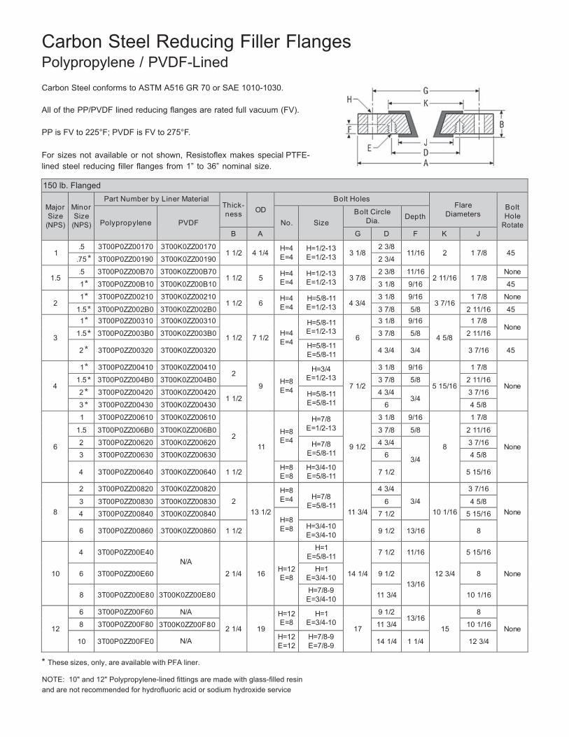
61
Carbon Steel Reducing Filler Flanges Polypropylene / PVDF-Lined
Carbon Steel conforms to ASTM A516 GR 70 or SAE 1010-1030.
All of the PP/PVDF lined reducing flanges are rated full vacuum (FV).
PP is FV to 225°F; PVDF is FV to 275°F.
For sizes not available or not shown, Resistoflex makes special PTFE-lined steel reducing filler flanges from 1” to 36” nominal size.
150 lb. Flanged Major Size
(NPS)
Minor Size
(NPS)
Part Number by Liner Material Thick- ness
OD
Bolt Holes Flare
Diameters
Bolt Hole
Rotate
Polypropylene
PVDF
No.
Size Bolt Circle
Dia.
Depth
B A G D F K J
1 .5 3T00P0ZZ00170 3T00K0ZZ00170
1 1/2
4 1/4 H=4 E=4
H=1/2-13 E=1/2-13
3 1/8
2 3/8 11/16
2
1 7/8
45
.75 3T00P0ZZ00190 3T00K0ZZ00190 2 3/4
1.5 .5 3T00P0ZZ00B70 3T00K0ZZ00B70
1 1/2
5 H=4 E=4
H=1/2-13 E=1/2-13
3 7/8
2 3/8 11/16 2 11/16
1 7/8
None
1 3T00P0ZZ00B10 3T00K0ZZ00B10 3 1/8 9/16 45
2 1 3T00P0ZZ00210 3T00K0ZZ00210
1 1/2
6 H=4 E=4
H=5/8-11 E=1/2-13
4 3/4
3 1/8 9/16 3 7/16
1 7/8 None
1.5 3T00P0ZZ002B0 3T00K0ZZ002B0 3 7/8 5/8 2 11/16 45
3
1 3T00P0ZZ00310 3T00K0ZZ00310
1 1/2
7 1/2
H=4 E=4
H=5/8-11 E=1/2-13
6
3 1/8 9/16
4 5/8
1 7/8 None
1.5 3T00P0ZZ003B0 3T00K0ZZ003B0 3 7/8 5/8 2 11/16
2 3T00P0ZZ00320
3T00K0ZZ00320 H=5/8-11
E=5/8-11
4 3/4
3/4
3 7/16
45
4
1 3T00P0ZZ00410 3T00K0ZZ00410 2
9
H=8 E=4
H=3/4 E=1/2-13
7 1/2
3 1/8 9/16 5 15/16
1 7/8
None 1.5 3T00P0ZZ004B0 3T00K0ZZ004B0 3 7/8 5/8 2 11/16
2 3T00P0ZZ00420 3T00K0ZZ00420 1 1/2 H=5/8-11
E=5/8-11 4 3/4
3/4 3 7/16
3 3T00P0ZZ00430 3T00K0ZZ00430 6 4 5/8
6
1 3T00P0ZZ00610 3T00K0ZZ00610
2
11
H=8 E=4
H=7/8 E=1/2-13
9 1/2
3 1/8 9/16
8
1 7/8
None
1.5 3T00P0ZZ006B0 3T00K0ZZ006B0 3 7/8 5/8 2 11/16
2 3T00P0ZZ00620 3T00K0ZZ00620 H=7/8 E=5/8-11
4 3/4
3/4
3 7/16
3 3T00P0ZZ00630 3T00K0ZZ00630 6 4 5/8
4 3T00P0ZZ00640
3T00K0ZZ00640
1 1/2 H=8
E=8 H=3/4-10 E=5/8-11
7 1/2
5 15/16
8
2 3T00P0ZZ00820 3T00K0ZZ00820
2
13 1/2
H=8 E=4
H=7/8
E=5/8-11
11 3/4
4 3/4
3/4
10 1/16
3 7/16
None 3 3T00P0ZZ00830 3T00K0ZZ00830 6 4 5/8
4 3T00P0ZZ00840 3T00K0ZZ00840 H=8 E=8
7 1/2 5 15/16
6 3T00P0ZZ00860
3T00K0ZZ00860
1 1/2 H=3/4-10
E=3/4-10
9 1/2
13/16
8
10
4
3T00P0ZZ00E40
N/A
2 1/4
16
H=12 E=8
H=1 E=5/8-11
14 1/4
7 1/2
11/16
12 3/4
5 15/16
None
6 3T00P0ZZ00E60 H=1
E=3/4-10
9 1/2
13/16
8
8
3T00P0ZZ00E80
3T00K0ZZ00E80 H=7/8-9
E=3/4-10
11 3/4
10 1/16
12
6 3T00P0ZZ00F60 N/A
2 1/4
19
H=12 E=8
H=1 E=3/4-10
17
9 1/2 13/16
15
8
None 8 3T00P0ZZ00F80 3T00K0ZZ00F80 11 3/4 10 1/16
10 3T00P0ZZ00FE0
N/A H=12
E=12 H=7/8-9 E=7/8-9
14 1/4
1 1/4
12 3/4
These sizes, only, are available with PFA liner.
NOTE: 10" and 12" Polypropylene-lined fittings are made with glass-filled resin and are not recommended for hydrofluoric acid or sodium hydroxide service
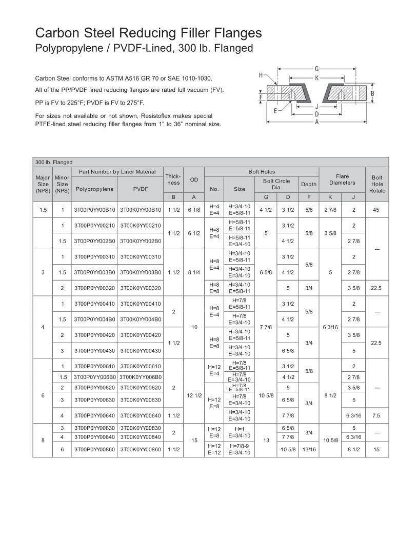
62
Carbon Steel Reducing Filler Flanges Polypropylene / PVDF-Lined, 300 lb. Flanged
Carbon Steel conforms to ASTM A516 GR 70 or SAE 1010-1030.
All of the PP/PVDF lined reducing flanges are rated full vacuum (FV).
PP is FV to 225°F; PVDF is FV to 275°F.
For sizes not available or not shown, Resistoflex makes special PTFE-lined steel reducing filler flanges from 1” to 36” nominal size.
300 lb. Flanged
Major Size
(NPS)
Minor Size
(NPS)
Part Number by Liner Material Thick- ness
OD
Bolt Holes Flare
Diameters
Bolt Hole
Rotate
Polypropylene
PVDF
No.
Size Bolt Circle
Dia.
Depth
B A G D F K J
1.5
1 3T00P0YY00B10
3T00K0YY00B10
1 1/2
6 1/8 H=4
E=4 H=3/4-10 E=5/8-11
4 1/2
3 1/2
5/8
2 7/8
2
45
1
3T00P0YY00210
3T00K0YY00210
1 1/2
6 1/2
H=8 E=4
H=5/8-11 E=5/8-11
5
3 1/2
5/8
3 5/8
2
---
1.5
3T00P0YY002B0
3T00K0YY002B0 H=5/8-11
E=3/4-10
4 1/2
2 7/8
3
1
3T00P0YY00310
3T00K0YY00310
1 1/2
8 1/4
H=8 E=4
H=3/4-10 E=5/8-11
6 5/8
3 1/2
5/8
5
2
1.5
3T00P0YY003B0
3T00K0YY003B0 H=3/4-10
E=3/4-10
4 1/2
2 7/8
2
3T00P0YY00320
3T00K0YY00320 H=8
E=8 H=3/4-10 E=5/8-11
5
3/4
3 5/8
22.5
4
1
3T00P0YY00410
3T00K0YY00410
2
10
H=8 E=4
H=7/8 E=5/8-11
7 7/8
3 1/2
5/8
6 3/16
2
--- 1.5
3T00P0YY004B0
3T00K0YY004B0 H=7/8
E=3/4-10
4 1/2
2 7/8
2
3T00P0YY00420
3T00K0YY00420
1 1/2
H=8 E=8
H=3/4-10 E=5/8-11
5
3/4
3 5/8
22.5 3
3T00P0YY00430
3T00K0YY00430 H=3/4-10
E=3/4-10
6 5/8
5
6
1
3T00P0YY00610
3T00K0YY00610
2
12 1/2
H=12 E=4
H=7/8 E=5/8-11
10 5/8
3 1/2
5/8
8 1/2
2
---
1.5 3T00P0YY006B0 3T00K0YY006B0 H=7/8 E= 3/4-10 4 1/2 2 7/8
2 3T00P0YY00620 3T00K0YY00620
H=12 E=8
H=7 /8 E =5 /8 -11 5
3/4
3 5/8
3 3T00P0YY00630
3T00K0YY00630 H=7/8
E=3/4-10
6 5/8
5
4
3T00P0YY00640
3T00K0YY00640
1 1/2 H=3/4-10
E=3/4-10
7 7/8
6 3/16
7.5
8
3 3T00P0YY00830 3T00K0YY00830 2
15
H=12 E=8
H=1 E=3/4-10
13
6 5/8 3/4
10 5/8
5 ---
4 3T00P0YY00840 3T00K0YY00840 7 7/8 6 3/16
6 3T00P0YY00860
3T00K0YY00860
1 1/2 H=12
E=12 H=7/8-9 E=3/4-10
10 5/8
13/16
8 1/2
15
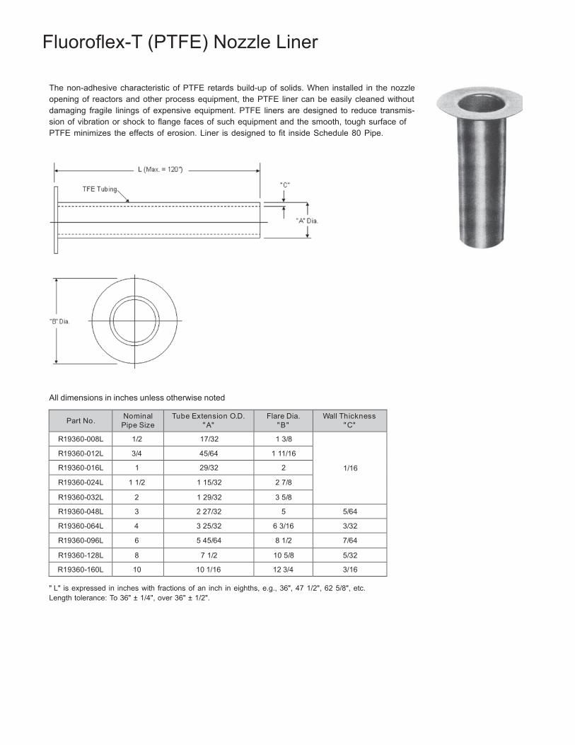
63
Fluoroflex-T (PTFE) Nozzle Liner
The non-adhesive characteristic of PTFE retards build-up of solids. When installed in the nozzle opening of reactors and other process equipment, the PTFE liner can be easily cleaned without damaging fragile linings of expensive equipment. PTFE liners are designed to reduce transmis- sion of vibration or shock to flange faces of such equipment and the smooth, tough surface of PTFE minimizes the effects of erosion. Liner is designed to fit inside Schedule 80 Pipe.
All dimensions in inches unless otherwise noted
Part No. Nominal
Pipe Size Tube Extension O.D.
" A" Flare Dia.
" B" Wall Thickness
" C"
R19360-008L 1/2 17/32 1 3/8
1/16
R19360-012L 3/4 45/64 1 11/16
R19360-016L 1 29/32 2
R19360-024L 1 1/2 1 15/32 2 7/8
R19360-032L 2 1 29/32 3 5/8
R19360-048L 3 2 27/32 5 5/64
R19360-064L 4 3 25/32 6 3/16 3/32
R19360-096L 6 5 45/64 8 1/2 7/64
R19360-128L 8 7 1/2 10 5/8 5/32
R19360-160L 10 10 1/16 12 3/4 3/16
" L" is expressed in inches with fractions of an inch in eighths, e.g., 36", 47 1/2", 62 5/8", etc. Length tolerance: To 36" ± 1/4", over 36" ± 1/2".
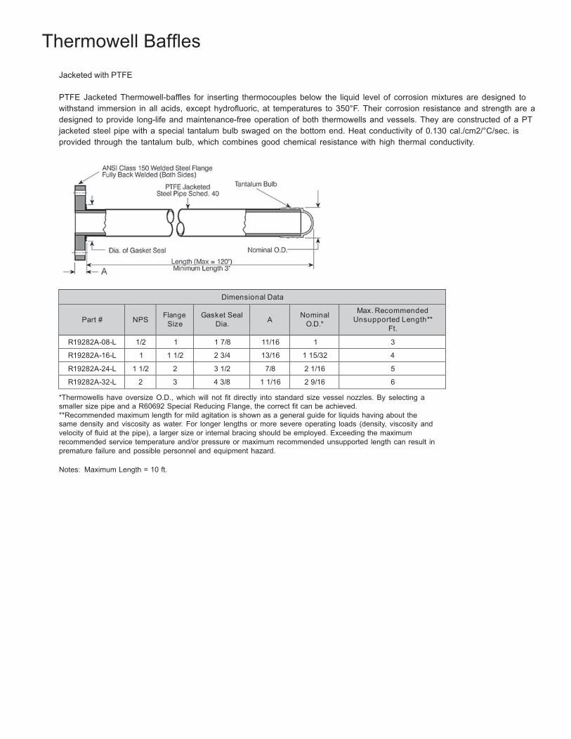
64
Thermowell Baffles
Jacketed with PTFE
PTFE Jacketed Thermowell-baffles for inserting thermocouples below the liquid level of corrosion mixtures are designed to withstand immersion in all acids, except hydrofluoric, at temperatures to 350°F. Their corrosion resistance and strength are a designed to provide long-life and maintenance-free operation of both thermowells and vessels. They are constructed of a PT jacketed steel pipe with a special tantalum bulb swaged on the bottom end. Heat conductivity of 0.130 cal./cm2/°C/sec. is provided through the tantalum bulb, which combines good chemical resistance with high thermal conductivity.
Dimensional Data
Part #
NPS
Flange
Size
Gasket Seal
Dia.
A
Nominal
O.D.*
Max. Recommended Unsupported Length**
Ft.
R19282A-08-L 1/2 1 1 7/8 11/16 1 3
R19282A-16-L 1 1 1/2 2 3/4 13/16 1 15/32 4
R19282A-24-L 1 1/2 2 3 1/2 7/8 2 1/16 5
R19282A-32-L 2 3 4 3/8 1 1/16 2 9/16 6
*Thermowells have oversize O.D., which will not fit directly into standard size vessel nozzles. By selecting a smaller size pipe and a R60692 Special Reducing Flange, the correct fit can be achieved. **Recommended maximum length for mild agitation is shown as a general guide for liquids having about the same density and viscosity as water. For longer lengths or more severe operating loads (density, viscosity and velocity of fluid at the pipe), a larger size or internal bracing should be employed. Exceeding the maximum recommended service temperature and/or pressure or maximum recommended unsupported length can result in premature failure and possible personnel and equipment hazard.
Notes: Maximum Length = 10 ft.
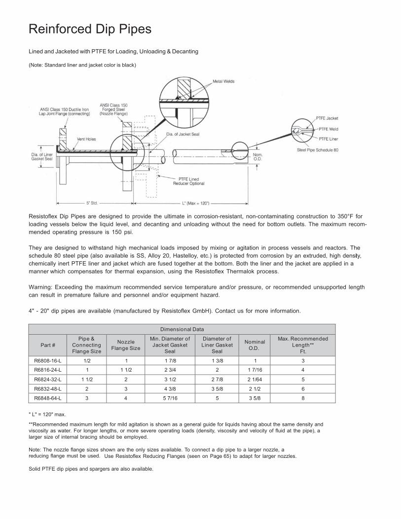
65
Reinforced Dip Pipes
Lined and Jacketed with PTFE for Loading, Unloading & Decanting
(Note: Standard liner and jacket color is black)
Resistoflex Dip Pipes are designed to provide the ultimate in corrosion-resistant, non-contaminating construction to 350°F for loading vessels below the liquid level, and decanting and unloading without the need for bottom outlets. The maximum recom- mended operating pressure is 150 psi.
They are designed to withstand high mechanical loads imposed by mixing or agitation in process vessels and reactors. The schedule 80 steel pipe (also available is SS, Alloy 20, Hastelloy, etc.) is protected from corrosion by an extruded, high density, chemically inert PTFE liner and jacket which are fused together at the bottom. Both the liner and the jacket are applied in a manner which compensates for thermal expansion, using the Resistoflex Thermalok process.
Warning: Exceeding the maximum recommended service temperature and/or pressure, or recommended unsupported length can result in premature failure and personnel and/or equipment hazard.
4" - 20" dip pipes are available (manufactured by Resistoflex GmbH). Contact us for more information.
Dimensional Data
Part #
Pipe & Connecting Flange Size
Nozzle
Flange Size
Min. Diameter of Jacket Gasket
Seal
Diameter of Liner Gasket
Seal
Nominal
O.D.
Max. Recommended Length**
Ft.
R6808-16-L 1/2 1 1 7/8 1 3/8 1 3
R6816-24-L 1 1 1/2 2 3/4 2 1 7/16 4
R6824-32-L 1 1/2 2 3 1/2 2 7/8 2 1/64 5
R6832-48-L 2 3 4 3/8 3 5/8 2 1/2 6
R6848-64-L 3 4 5 7/16 5 3 5/8 8
" L" = 120" max.
**Recommended maximum length for mild agitation is shown as a general guide for liquids having about the same density and viscosity as water. For longer lengths, or more severe operating loads (density, viscosity and velocity of fluid at the pipe), a larger size of internal bracing should be employed.
Note: The nozzle flange sizes shown are the only sizes available. To connect a dip pipe to a larger nozzle, a reducing flange must be used. Use Resistoflex Reducing Flanges (seen on Page 65) to adapt for larger nozzles.
Solid PTFE dip pipes and spargers are also available.
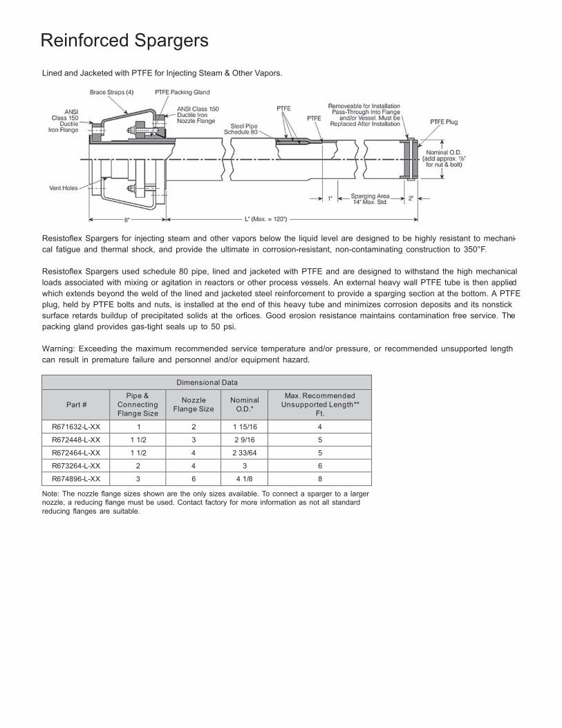
66
Reinforced Spargers
Lined and Jacketed with PTFE for Injecting Steam & Other Vapors.
Resistoflex Spargers for injecting steam and other vapors below the liquid level are designed to be highly resistant to mechani- cal fatigue and thermal shock, and provide the ultimate in corrosion-resistant, non-contaminating construction to 350°F.
Resistoflex Spargers used schedule 80 pipe, lined and jacketed with PTFE and are designed to withstand the high mechanical loads associated with mixing or agitation in reactors or other process vessels. An external heavy wall PTFE tube is then applied which extends beyond the weld of the lined and jacketed steel reinforcement to provide a sparging section at the bottom. A PTFE plug, held by PTFE bolts and nuts, is installed at the end of this heavy tube and minimizes corrosion deposits and its nonstick surface retards buildup of precipitated solids at the orfices. Good erosion resistance maintains contamination free service. The packing gland provides gas-tight seals up to 50 psi.
Warning: Exceeding the maximum recommended service temperature and/or pressure, or recommended unsupported length can result in premature failure and personnel and/or equipment hazard.
Dimensional Data
Part #
Pipe & Connecting Flange Size
Nozzle
Flange Size
Nominal
O.D.*
Max. Recommended Unsupported Length**
Ft.
R671632-L-XX 1 2 1 15/16 4
R672448-L-XX 1 1/2 3 2 9/16 5
R672464-L-XX 1 1/2 4 2 33/64 5
R673264-L-XX 2 4 3 6
R674896-L-XX 3 6 4 1/8 8
Note: The nozzle flange sizes shown are the only sizes available. To connect a sparger to a larger nozzle, a reducing flange must be used. Contact factory for more information as not all standard reducing flanges are suitable.
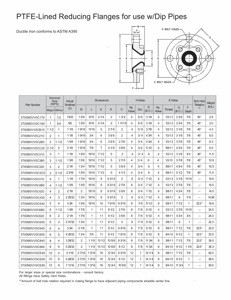
PTFE-Lined Reducing Flanges for use w/Dip Pipes Ductile Iron conforms to ASTM A395
Part Number
Nominal Size
(NPS)
Actual
Smallest I.D.
Dimensions
H Holes
E Holes
Bolt Hole Rotation
**
Weight (lbs.)
B
J
A
K
C No. Holes
Dia.
D (B.C.)
No. Holes
Thread G
(B.C.) F
Depth Major Minor
3T00M0VV0C170 1 1/2 13/32 1 5/8 9/16 4 1/4 2 1 3/ 8 4 5/ 8 3 1/8 4 1/2-13 2 3/8 7/8 45° 2.8
3T00M0VV0C190 1 3/4 5/8 1 5/8 9/16 4 1/4 2 1 11/16 4 5/ 8 3 1/8 4 1/2-13 2 3/4 7/8 45° 3.0
3T60B0VV0CB10 1 1/2 1 1 1/8 1 9/16 11/16 5 2 7/ 8 2 4 5/ 8 3 7/8 4 1/2-13 3 1/8 7/8 45° 4.3
3T60B0VV0C210 2 1 1 1/8 1 9/16 3/4 6 3 5/ 8 2 4 3/ 4 4 3/4 4 1/2-13 3 1/8 7/8 45° 6.0
3T60B0VV0C2B0 2 1 1/2 1 5/8 1 9/16 3/4 6 3 5/ 8 2 7/8 4 3/ 4 4 3/4 4 1/2-13 3 7/8 7/8 45° 6.3
3T60B0VV0CC20 2 1/2 2 2 1/8 1 9/16 7/8 7 4 1/ 8 3 5/8 4 3/ 4 5 1/2 4 5/8-11 4 3/4 7/8 45° 9.0
3T60B0VV0C310 3 1 1 1/8 1 5/8 15/16 7 1/2 5 2 4 3/ 4 6 4 1/2-13 3 1/8 3/4 45° 11.5
3T60B0VV0C3B0 3 1 1/2 1 5/8 1 5/8 15/16 7 1/2 5 2 7/ 8 4 3 / 4 6 4 1/2-13 3 7/8 7/8 45° 12.8
3T60B0VV0C320 3 2 2 1/8 1 3/4 15/16 7 1/2 5 3 5/ 8 4 3/ 4 6 4 5/8-11 4 3/4 7/8 45° 10.5
3T00M0VV0C3C0 3 2 1/2 2 3/16 1 5/8 13/16 7 1/2 5 4 1/ 5 4 3/ 4 6 4 5/8-11 5 1/2 7/8 45° 11.0
3T60B0VV0C410 4 1 1 1/8 1 7/8 15/16 9 6 3/16 2 8 3/ 4 7 1/2 4 1/2-13 3 1/8 11/16 -- 15.8
3T60B0VV0C4B0 4 1 1/2 1 5/8 1 5/8 15/16 9 6 3/16 2 7/8 8 3/ 4 7 1/2 4 1/2-13 3 7/8 7/8 -- 15.5
3T60B0VV0C420 4 2 2 1/8 2 15/16 9 6 3/16 3 5/8 8 3/ 4 7 1/2 4 5/8-11 4 3/4 7/8 -- 14.5
3T00M0VV0C430 4 3 2 25/32 1 3/4 15/16 9 6 3/16 5 8 3/ 4 7 1/2 4 5/8-11 6 7/ 8 -- 14.58
3T00M0VV0C540 5 4 3 3/4 1 5/8 15/16 10 7 5/16 6 3/16 8 7/ 8 8 1/2 8 5/8-11 7 1/2 1 22.5° 16.8
3T60B0VV0C6B0 6 1 1/2 1 5/8 1 7/8 1 11 8 1/2 2 7/8 8 7/ 8 9 1/2 4 1/2-13 3 7/8 11/16 -- 24.5
3T60B0VV0C620 6 2 2 1/8 1 7/8 1 11 8 1/2 3 5/8 8 7/ 8 9 1/2 4 5/8-11 4 3/4 3/4 -- 24.3
3T00M0VV0C630 6 3 2 31/32 1 3/4 1 11 8 1/2 5 8 7/ 8 9 1/2 4 5/8-11 6 1 - - 22.3
3T00M0VV0C640 6 4 3 3/4 2 1/8 1 11 8 1/2 6 3/16 8 7/ 8 9 1/2 8 5/8-11 7 1/2 7/8 22.5° 22.0
3T00M0VV0C650 6 5 4 25/32 1 3/4 7/8 11 8 1/2 7 5/16 8 7/ 8 9 1/2 8 3/4-10 8 1/2 1 22.5° 22.0
3T00M0VV0C840 8 4 3 29/32 2 1 1/ 8 13 1/2 10 5/8 6 3/16 8 7/ 8 11 3/4 8 5/8-11 7 1/2 7/8 22.5° 39.5
3T00M0VV0C860 8 6 5 25/32 2 1 1/ 8 13 1/2 10 5/8 8 1/2 8 7/ 8 11 3/4 8 3/4-10 9 1/2 1 1/8 22.5° 36.3
3T00M0VV0CE40 10 4 4 1/16 2 7/16 1 3/16 16 12 3/4 6 3/16 12 1 14 1/ 4 8 5/8-11 7 1/2 7/8 -- 62.0
3T00M0VV0CE60 10 6 5 29/32 2 7/16 1 3/16 16 12 3/4 8 1/2 12 1 14 1/ 4 8 3/4-10 9 1/2 1 - - 58.5
3T00M0VV0CE80 10 8 7 11/16 2 7/16 1 3/16 16 12 3/4 10 5/8 12 1 14 1/ 4 8 3/4-10 11 3/4 1 - - 50.0
For larger sizes or special size combinations - consult factory. All fittings have Safety Vent Holes.
**Amount of bolt hole rotation required in mating flange to have adjacent piping components straddle center line. . "3T6" Series reducing flanges have extra large bores to accommodate the oversized O.D. of reinforced dip pipes, spargers and thermowells through 2" nominal pipe size. 65
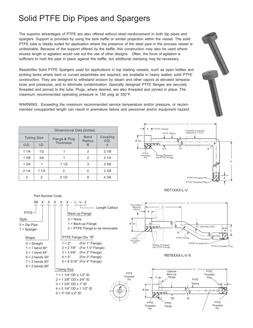
Solid PTFE Dip Pipes and Spargers
The superior advantages of PTFE are also offered without steel reinforcement in both dip pipes and spargers. Support is provided by using the tank baffle or similar projection within the vessel. The solid PTFE tube is ideally suited for application where the presence of the steel pipe in the process vessel is undesirable. Because of the support offered by the baffle, this construction may also be used where excess length or agitation would rule out the use of other designs. Often, the force of agitation is sufficient to hold the pipe in place against the baffle, but additional clamping may be necessary.
Resistoflex Solid PTFE Spargers used for applications in top loading vessels, such as open kettles and pickling tanks where bent or curved assemblies are required, are available in heavy walled, solid PTFE construction. They are designed to withstand erosion by steam and other vapors at elevated tempera- tures and pressures, and to eliminate contamination. Specially designed PTFE flanges are securely threaded and pinned to the tube. Plugs, where desired, are also threaded and pinned in place. The maximum recommended operating pressure is 150 psig at 350°F.
WARNING: Exceeding the maximum recommended service temperature and/or pressure, or recom- mended unsupported length can result in premature failure and personnel and/or equipment hazard.
Dimensional Data (inches)
Tubing Size
Flange & Plug Thickness
Bend Radius
R
Coupling O.D.
X O.D. I.D.
1 1/4 1/2 1 2 2 1/8
1 3/8 3/4 1 2 2 1/4
1 3/4 1 1 1/2 3 2 5/8
2 1/4 1 1/2 2 4 3 3/8
3 2 2 1/2 8 4 3/8
Part Number Code:
R671XXX-L-V
R6
PTFE
Style
X X X X X - L - V - Z
Back-up Flange
0 = None
Length Callout
5 = Dip Pipe 7 = Sparger
1 = Back-up Flange 2 = PTFE Flange to be removable
Shape
0 = Straight 1 = 1 bend 90o
2 = 1 bend 45o
6 = 2 bends 30o
7 = 2 bends 45o
8 = 2 bends 90o
PTFE Flange Dia. "B"
1 = 2" (For 1" Flange) 2 = 2 7/8" (For 1.5" Flange) 3 = 3 5/8" (For 2" Flange) 4 = 5" (For 3" Flange) 5 = 6 3/16" (For 4" Flange)
Tubing Size
1 = 1 1/4" OD x 1/2" ID 2 = 1 3/8" OD x 3/4" ID
PTFE Threaded
Pin
R676XXX-L-V-X
Optional Back-Up
A Flange
PTFE
PTFE Threaded
Plug
3 = 1 3/4" OD x 1" ID 4 = 2 1/4" OD x 1 1/2" ID 5 = 3" OD x 2" ID
66
B Dia.
PTFE Threaded
Pin
OD ID
PTFE Flange
R670XXX-L
Tubing A
PTFE Threaded
Pin
Customer-Specified
Drill Pattern
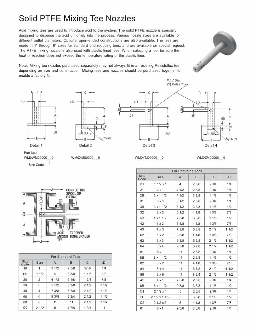
For Reducing Tees
Size Code Size A B C I.D.
B1 1 1/2 x 1 4 2 5/8 9/16 1/4
21 2 x 1 4 1/2 2 5/8 9/16 1/4
2B 2 x 1 1/2 4 1/2 3 3/8 1 1/8 1/2
31 3 x 1 5 1/2 2 5/8 9/16 1/4
3B 3 x 1 1/2 5 1/2 3 3/8 1 1/8 1/2
32 3 x 2 5 1/2 4 1/8 1 3/8 7/8
4B 4 x 1 1/2 7 3/8 3 3/8 1 1/8 1/2
42 4 x 2 7 3/8 4 1/8 1 3/8 7/8
43 4 x 3 7 3/8 5 3/8 2 1/2 1 1/2
62 6 x 2 9 3/8 4 1/8 1 3/8 7/8
63 6 x 3 9 3/8 5 3/8 2 1/2 1 1/2
64 6 x 4 9 3/8 6 7/8 2 1/2 1 1/2
81 8 x 1 11 2 5/8 9/16 1/4
8B 8 x 1 1/2 11 2 3/8 1 1/8 1/2
82 8 x 2 11 4 1/8 1 3/8 7/8
84 8 x 4 11 6 7/8 2 1/2 1 1/2
86 8 x 6 11 8 3/4 2 1/2 1 1/2
41 4 x 1 7 3/8 2 5/8 9/16 1/4
6B 6 x 1 1/2 9 3/8 3 3/8 1 1/8 1/2
C1 2 1/2 x 1 5 2 5/8 9/16 1/4
CB 2 1/2 x 1 1/2 5 3 3/8 1 1/8 1/2
C2 2 1/2 x 2 5 4 1/8 1 3/8 7/8
61 6 x 1 9 3/8 2 5/8 9/16 1/4
Solid PTFE Mixing Tee Nozzles
Acid mixing tees are used to introduce acid to the system. The solid PTFE nozzle is specially designed to disperse the acid uniformly into the process. Various nozzle sizes are available for different outlet diameters. Optional open-ended constructions are also available. The tees are made in 1" through 8" sizes for standard and reducing tees, and are available on special request. The PTFE mixing nozzle is also used with plastic lined tees. When selecting a tee, be sure the heat of reaction does not exceed the temperature rating of the plastic liner.
Note: Mixing tee nozzles purchased separately may not always fit in an existing Resistoflex tee, depending on size and construction. Mixing tees and nozzles should be purchased together to enable a factory fit.
Detail 1 Detail 2 Detail 3 Detail 4
Part No.: WM0WM00000_ _0 WM0XM00000_ _0 WM0YM00000_ _0 WM0ZM00000_ _0
Size Code
For Standard Tees Size Code Size A B C I.D.
10 1 3 1/2 2 5/8 9/16 1/4
B0 1 1/2 4 3 3/8 1 1/5 1/2
20 2 4 1/ 2 4 1/8 1 3/8 7/8 30 3 5 1/2 5 3/8 2 1/2 1 1/2
40 4 7 3/8 6 7/8 2 1/2 1 1/2
60 6 9 3/ 8 8 3/4 2 1/2 1 1/2
80 8 11 11 2 1/2 1 1/2 C0 2 1/ 2 5 4 7/8 1 3/4 1
Note: PTFE Mixing Tee Nozzles are made with glass-filled resin and are not recommended for hydrofluoric acid or sodium hydroxide service 67
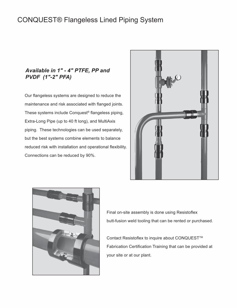
68
CONQUEST® Flangeless Lined Piping System
Available in 1" - 4" PTFE, PP and PVDF (1"-2" PFA)
Our flangeless systems are designed to reduce the
maintenance and risk associated with flanged joints.
These systems include Conquest® flangeless piping,
Extra-Long Pipe (up to 40 ft long), and MultiAxis
piping. These technologies can be used separately,
but the best systems combine elements to balance
reduced risk with installation and operational flexibility.
Connections can be reduced by 90%.
Final on-site assembly is done using Resistoflex
butt-fusion weld tooling that can be rented or purchased.
Contact Resistoflex to inquire about CONQUESTTM
Fabrication Certification Training that can be provided at
your site or at our plant.
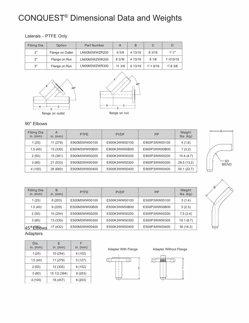
69
Fitting Dia. in. (mm)
B in. (mm)
PTFE
PVDF
PP Weight
lbs. (kg)
1 (25) 8 (203) E500M3WW00100 E500K3WW00100 E500P3WW00100 3 (1.4)
1.5 (40) 9 (229) E500M3WW00B00 E500K3WW00B00 E500P3WW00B00 5 (2.3)
2 (50) 10 (254) E500M3WW00200 E500K3WW00200 E500P3WW00200 7.5 (3.4)
3 (80) 13 (330) E500M3WW00300 E500K3WW00300 E500P3WW00300 19.1 (8.7)
4 (100) 17 (432) E500M3WW00400 E500K3WW00400 E500P3WW00400 36 (16.3)
Dia. in. (mm)
E in. (mm)
F in. (mm)
1 (25) 10 (254) 4 (102)
1.5 (40) 11 (279) 5 (127)
2 (50) 12 (305) 6 (152)
3 (80) 15 1/2 (394) 8 (203)
4 (100) 18 (457) 8 (203)
CONQUEST® Dimensional Data and Weights
Laterals - PTFE Only
Fitting Dia. Option Part Number A B C D
2" Flange on Outlet LN00M3WWZR200 6 5/8 4 13/16 8 3/16 1'-1"
2" Flange on Run LN00M3WZWR200 8 3/16 4 13/16 8 1/8 1'-015/16
3" Flange on Run LN00M3WZWR300 11 3/8 6 13/16 1'-1 9/16 1'-8 3/8
flange on outlet flange on run
90° Elbows
Fitting Dia.
in. (mm) A
in. (mm)
PTFE
PVDF
PP Weight
lbs. (kg)
1 (25) 11 (279) E900M3WW00100 E900K3WW00100 E900P3WW00100 4 (1.8)
1.5 (40) 13 (330) E900M3WW00B00 E900K3WW00B00 E900P3WW00B00 7 (3.2)
2 (50) 15 (381) E900M3WW00200 E900K3WW00200 E900P3WW00200 10.4 (4.7)
3 (80) 21 (533) E900M3WW00300 E900K3WW00300 E900P3WW00300 28.5 (13.2)
4 (100) 26 (660) E900M3WW00400 E900K3WW00400 E900P3WW00400 50.1 (22.7)
45° Elbows
Adapters
Adapter With Flange Adapter Without Flange
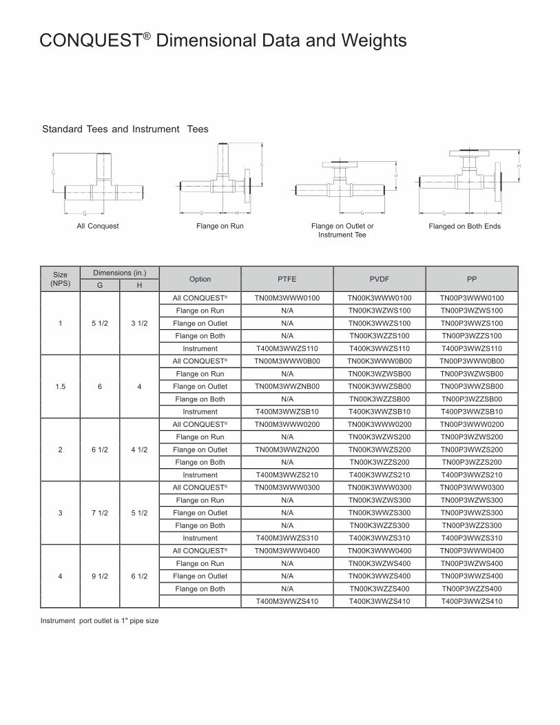
70
CONQUEST® Dimensional Data and Weights
Standard Tees and Instrument Tees
All Conquest Flange on Run Flange on Outlet or Instrument Tee
Flanged on Both Ends
Size (NPS)
Dimensions (in.) Option
PTFE
PVDF
PP
G H
1
5 1/2
3 1/2
All CONQUEST® TN00M3WWW0100 TN00K3WWW0100 TN00P3WWW0100
Flange on Run N/A TN00K3WZWS100 TN00P3WZWS100
Flange on Outlet N/A TN00K3WWZS100 TN00P3WWZS100
Flange on Both N/A TN00K3WZZS100 TN00P3WZZS100
Instrument T400M3WWZS110 T400K3WWZS110 T400P3WWZS110
1.5
6
4
All CONQUEST® TN00M3WWW0B00 TN00K3WWW0B00 TN00P3WWW0B00
Flange on Run N/A TN00K3WZWSB00 TN00P3WZWSB00
Flange on Outlet TN00M3WWZNB00 TN00K3WWZSB00 TN00P3WWZSB00
Flange on Both N/A TN00K3WZZSB00 TN00P3WZZSB00
Instrument T400M3WWZSB10 T400K3WWZSB10 T400P3WWZSB10
2
6 1/2
4 1/2
All CONQUEST® TN00M3WWW0200 TN00K3WWW0200 TN00P3WWW0200
Flange on Run N/A TN00K3WZWS200 TN00P3WZWS200
Flange on Outlet TN00M3WWZN200 TN00K3WWZS200 TN00P3WWZS200
Flange on Both N/A TN00K3WZZS200 TN00P3WZZS200
Instrument T400M3WWZS210 T400K3WWZS210 T400P3WWZS210
3
7 1/2
5 1/2
All CONQUEST® TN00M3WWW0300 TN00K3WWW0300 TN00P3WWW0300
Flange on Run N/A TN00K3WZWS300 TN00P3WZWS300
Flange on Outlet N/A TN00K3WWZS300 TN00P3WWZS300
Flange on Both N/A TN00K3WZZS300 TN00P3WZZS300
Instrument T400M3WWZS310 T400K3WWZS310 T400P3WWZS310
4
9 1/2
6 1/2
All CONQUEST® TN00M3WWW0400 TN00K3WWW0400 TN00P3WWW0400
Flange on Run N/A TN00K3WZWS400 TN00P3WZWS400
Flange on Outlet N/A TN00K3WWZS400 TN00P3WWZS400
Flange on Both N/A TN00K3WZZS400 TN00P3WZZS400
T400M3WWZS410 T400K3WWZS410 T400P3WWZS410
Instrument port outlet is 1" pipe size
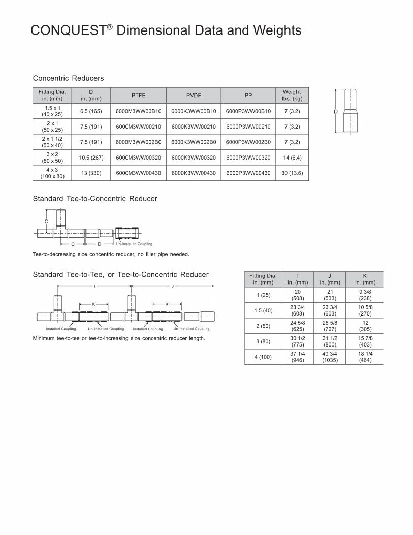
71
Fitting Dia. in. (mm)
I in. (mm)
J in. (mm)
K in. (mm)
1 (25) 20
(508) 21
(533) 9 3/8 (238)
1.5 (40) 23 3/4
(603) 23 3/4 (603)
10 5/8 (270)
2 (50) 24 5/8
(625) 28 5/8 (727)
12 (305)
3 (80) 30 1/2
(775) 31 1/2 (800)
15 7/8 (403)
4 (100) 37 1/4
(946) 40 3/4 (1035)
18 1/4 (464)
CONQUEST® Dimensional Data and Weights
Concentric Reducers
Fitting Dia. in. (mm)
D in. (mm)
PTFE
PVDF
PP Weight
lbs. (kg)
1.5 x 1 (40 x 25)
6.5 (165)
6000M3WW00B10
6000K3WW00B10
6000P3WW00B10
7 (3.2)
2 x 1 (50 x 25)
7.5 (191)
6000M3WW00210
6000K3WW00210
6000P3WW00210
7 (3.2)
2 x 1 1/2 (50 x 40)
7.5 (191)
6000M3WW002B0
6000K3WW002B0
6000P3WW002B0
7 (3.2)
3 x 2 (80 x 50)
10.5 (267)
6000M3WW00320
6000K3WW00320
6000P3WW00320
14 (6.4)
4 x 3 (100 x 80)
13 (330)
6000M3WW00430
6000K3WW00430
6000P3WW00430
30 (13.6)
Standard Tee-to-Concentric Reducer
Tee-to-decreasing size concentric reducer, no filler pipe needed.
Standard Tee-to-Tee, or Tee-to-Concentric Reducer
Minimum tee-to-tee or tee-to-increasing size concentric reducer length.
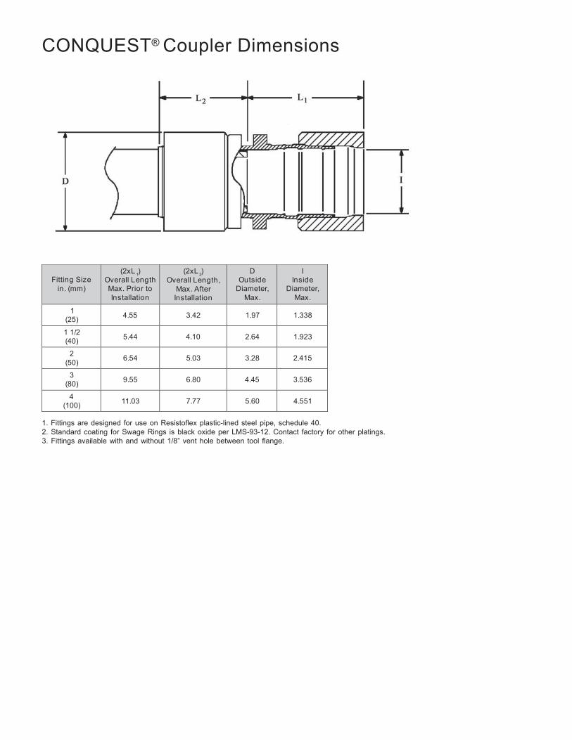
72
Fitting Size
in. (mm)
(2xL ) Overall Length Max. Prior to Installation
(2xL ) Overall Length,
Max. After Installation
D Outside
Diameter, Max.
I Inside
Diameter, Max.
1 (25)
4.55
3.42
1.97
1.338
1 1/2 (40)
5.44
4.10
2.64
1.923
2 (50)
6.54
5.03
3.28
2.415
3 (80)
9.55
6.80
4.45
3.536
4 (100)
11.03
7.77
5.60
4.551
CONQUEST® Coupler Dimensions
1 2
1. Fittings are designed for use on Resistoflex plastic-lined steel pipe, schedule 40. 2. Standard coating for Swage Rings is black oxide per LMS-93-12. Contact factory for other platings. 3. Fittings available with and without 1/8” vent hole between tool flange.
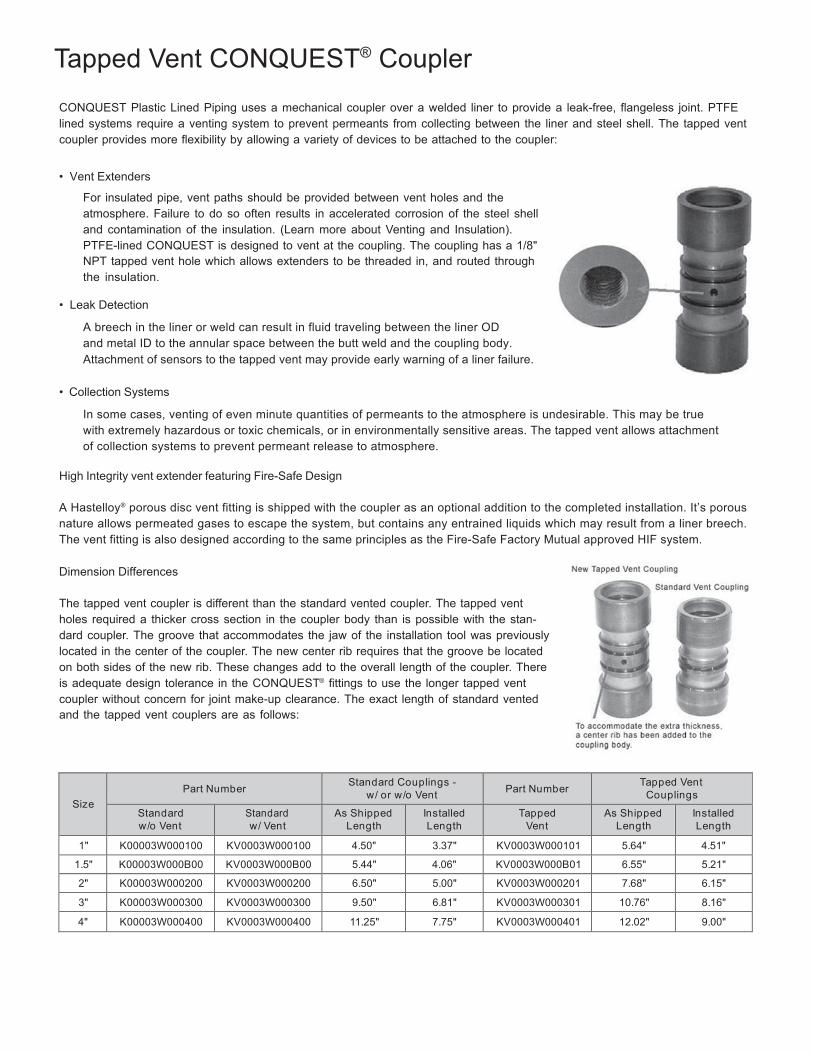
73
Tapped Vent CONQUEST® Coupler
CONQUEST Plastic Lined Piping uses a mechanical coupler over a welded liner to provide a leak-free, flangeless joint. PTFE lined systems require a venting system to prevent permeants from collecting between the liner and steel shell. The tapped vent coupler provides more flexibility by allowing a variety of devices to be attached to the coupler:
• Vent Extenders
For insulated pipe, vent paths should be provided between vent holes and the atmosphere. Failure to do so often results in accelerated corrosion of the steel shell and contamination of the insulation. (Learn more about Venting and Insulation). PTFE-lined CONQUEST is designed to vent at the coupling. The coupling has a 1/8" NPT tapped vent hole which allows extenders to be threaded in, and routed through the insulation.
• Leak Detection
A breech in the liner or weld can result in fluid traveling between the liner OD and metal ID to the annular space between the butt weld and the coupling body. Attachment of sensors to the tapped vent may provide early warning of a liner failure.
• Collection Systems
In some cases, venting of even minute quantities of permeants to the atmosphere is undesirable. This may be true with extremely hazardous or toxic chemicals, or in environmentally sensitive areas. The tapped vent allows attachment of collection systems to prevent permeant release to atmosphere.
High Integrity vent extender featuring Fire-Safe Design
A Hastelloy® porous disc vent fitting is shipped with the coupler as an optional addition to the completed installation. It’s porous nature allows permeated gases to escape the system, but contains any entrained liquids which may result from a liner breech. The vent fitting is also designed according to the same principles as the Fire-Safe Factory Mutual approved HIF system.
Dimension Differences
The tapped vent coupler is different than the standard vented coupler. The tapped vent holes required a thicker cross section in the coupler body than is possible with the stan- dard coupler. The groove that accommodates the jaw of the installation tool was previously located in the center of the coupler. The new center rib requires that the groove be located on both sides of the new rib. These changes add to the overall length of the coupler. There is adequate design tolerance in the CONQUEST® fittings to use the longer tapped vent coupler without concern for joint make-up clearance. The exact length of standard vented and the tapped vent couplers are as follows:
Size
Part Number Standard Couplings -
w / or w /o Vent
Part Number Tapped Vent
Couplings
Standard w /o Vent
Standard w / Vent
As Shipped Length
Installed Length
Tapped Vent
As Shipped Length
Installed Length
1" K00003W000100 KV0003W000100 4.50" 3.37" KV0003W000101 5.64" 4.51"
1.5" K00003W000B00 KV0003W000B00 5.44" 4.06" KV0003W000B01 6.55" 5.21"
2" K00003W000200 KV0003W000200 6.50" 5.00" KV0003W000201 7.68" 6.15"
3" K00003W000300 KV0003W000300 9.50" 6.81" KV0003W000301 10.76" 8.16"
4" K00003W000400 KV0003W000400 11.25" 7.75" KV0003W000401 12.02" 9.00"
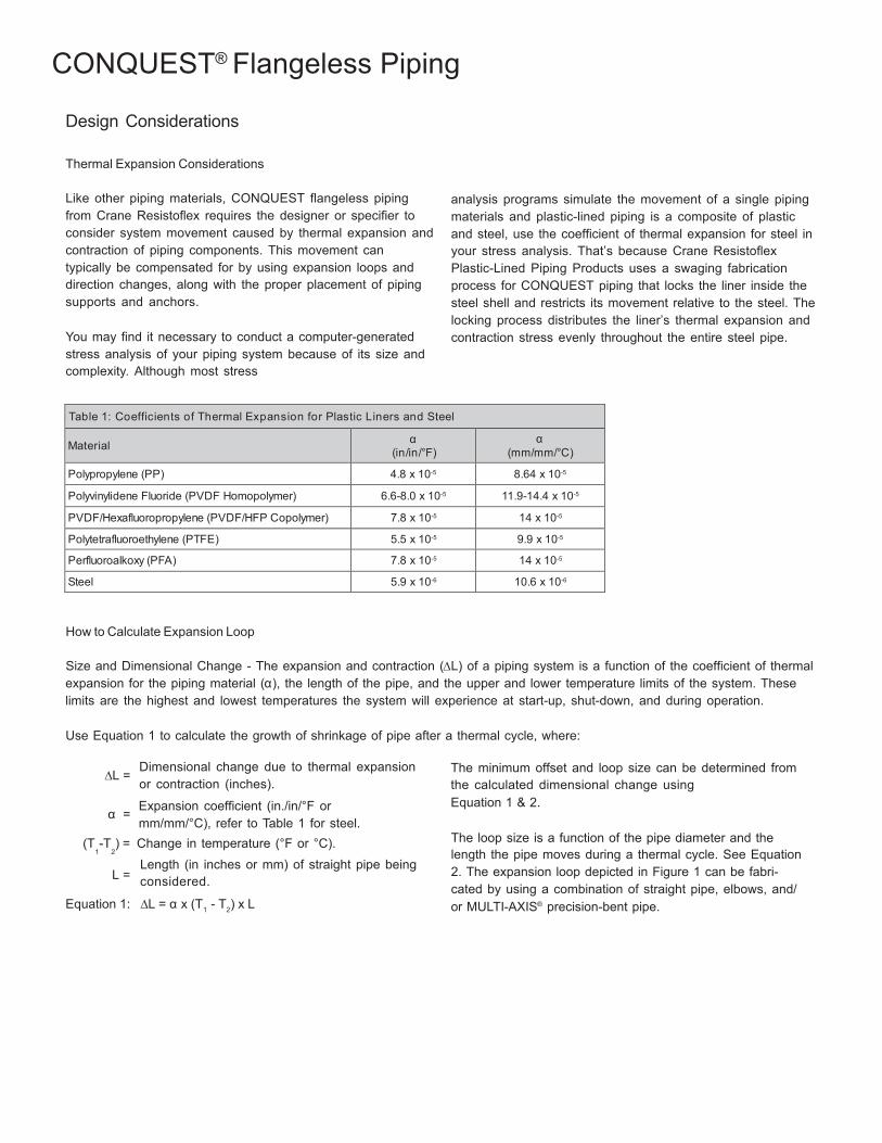
74
2 1
CONQUEST® Flangeless Piping
Design Considerations
Thermal Expansion Considerations
Like other piping materials, CONQUEST flangeless piping from Crane Resistoflex requires the designer or specifier to consider system movement caused by thermal expansion and contraction of piping components. This movement can typically be compensated for by using expansion loops and direction changes, along with the proper placement of piping supports and anchors.
You may find it necessary to conduct a computer-generated stress analysis of your piping system because of its size and complexity. Although most stress
analysis programs simulate the movement of a single piping materials and plastic-lined piping is a composite of plastic and steel, use the coefficient of thermal expansion for steel in your stress analysis. That’s because Crane Resistoflex Plastic-Lined Piping Products uses a swaging fabrication process for CONQUEST piping that locks the liner inside the steel shell and restricts its movement relative to the steel. The locking process distributes the liner’s thermal expansion and contraction stress evenly throughout the entire steel pipe.
Table 1: Coefficients of Thermal Expansion for Plastic Liners and Steel Material α
(in/in/°F) α
(mm/mm/°C)
Polypropylene (PP) 4.8 x 10⁻⁵ 8.64 x 10⁻⁵
Polyvinylidene Fluoride (PVDF Homopolymer) 6.6-8.0 x 10⁻⁵ 11.9-14.4 x 10⁻⁵
PVDF/Hexafluoropropylene (PVDF/HFP Copolymer) 7.8 x 10⁻⁵ 14 x 10-5
Polytetrafluoroethylene (PTFE) 5.5 x 10⁻⁵ 9.9 x 10⁻⁵
Perfluoroalkoxy (PFA) 7.8 x 10⁻⁵ 14 x 10-5
Steel 5.9 x 10⁻⁶ 10.6 x 10⁻⁶
How to Calculate Expansion Loop
Size and Dimensional Change - The expansion and contraction (∆L) of a piping system is a function of the coefficient of thermal expansion for the piping material (α), the length of the pipe, and the upper and lower temperature limits of the system. These limits are the highest and lowest temperatures the system will experience at start-up, shut-down, and during operation.
Use Equation 1 to calculate the growth of shrinkage of pipe after a thermal cycle, where:
∆L =
α =
Dimensional change due to thermal expansion or contraction (inches).
Expansion coefficient (in./in/°F or mm/mm/°C), refer to Table 1 for steel.
The minimum offset and loop size can be determined from the calculated dimensional change using Equation 1 & 2.
(T -T ) = Change in temperature (°F or °C). 1 2
Length (in inches or mm) of straight pipe being L = considered.
The loop size is a function of the pipe diameter and the length the pipe moves during a thermal cycle. See Equation 2. The expansion loop depicted in Figure 1 can be fabri- cated by using a combination of straight pipe, elbows, and/
Equation 1: ∆L = α x (T - T ) x L or MULTI-AXIS® precision-bent pipe.
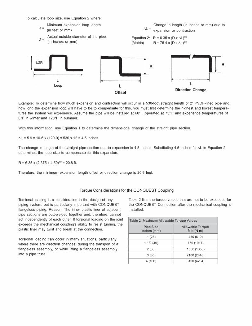
75
Table 2: Maximum Allow able Torque Values
Pipe Size inches (mm)
Allow able Torque ft-lb (N-m)
1 (25) 450 (610)
1 1/2 (40) 750 (1017)
2 (50) 1000 (1356)
3 (80) 2100 (2848)
4 (100) 3100 (4204)
To calculate loop size, use Equation 2 where:
Minimum expansion loop length
Change in length (in inches or mm) due to R = (in feet or mm) ∆L = expansion or contraction
Actual outside diameter of the pipe
D = (in inches or mm)
Equation 2: R = 6.35 x (D x ∆L)1/2
(Metric) R = 76.4 x (D x ∆L)1/2
Example: To determine how much expansion and contraction will occur in a 530-foot straight length of 2" PVDF-lined pipe and how long the expansion loop will have to be to compensate for this, you must first determine the highest and lowest tempera- tures the system will experience. Assume the pipe will be installed at 60°F, operated at 75°F, and experience temperatures of 0°F in winter and 120°F in summer.
With this information, use Equation 1 to determine the dimensional change of the straight pipe section. ∆L = 5.9 x 10-6 x (120-0) x 530 x 12 = 4.5 inches
The change in length of the straight pipe section due to expansion is 4.5 inches. Substituting 4.5 inches for ∆L in Equation 2, determines the loop size to compensate for this expansion.
R = 6.35 x (2.375 x 4.50)1/2 = 20.8 ft.
Therefore, the minimum expansion length offset or direction change is 20.8 feet.
Torque Considerations for the CONQUEST Coupling
Torsional loading is a consideration in the design of any piping system, but is particularly important with CONQUEST flangeless piping. Reason: The inner plastic liner of adjacent pipe sections are butt-welded together and, therefore, cannot act independently of each other. If torsional loading on the joint exceeds the mechanical coupling’s ability to resist turning, the plastic liner may twist and break at the connection.
Torsional loading can occur in many situations, particularly where there are direction changes, during the transport of a flangeless assembly, or while lifting a flangeless assembly into a pipe truss.
Table 2 lists the torque values that are not to be exceeded for the CONQUEST Connection after the mechanical coupling is installed.
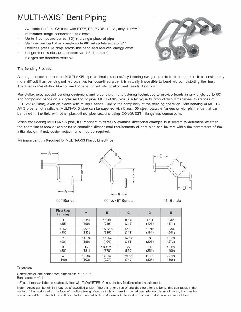
76
MULTI-AXIS® Bent Piping
· Available in 1" - 4" CS lined with PTFE, PP, PVDF (1" - 2", only, in PFA)* · Eliminates flange connections at elbows · Up to 4 compound bends (3D) in a single piece of pipe · Sections are bent at any angle up to 90° with a tolerance of ±1° · Reduces pressure drop across the bend and reduces energy costs · Longer bend radius (3 diameters vs. 1.5 diameters) · Flanges are threaded rotatable
The Bending Process
Although the concept behind MULTI-AXIS pipe is simple, successfully bending swaged plastic-lined pipe is not. It is considerably more difficult than bending unlined pipe. As for loose-lined pipe, it is virtually impossible to bend without distorting the liner. The liner in Resistoflex Plastic-Lined Pipe is locked into position and resists distortion.
Resistoflex uses special bending equipment and proprietary manufacturing techniques to provide bends in any angle up to 90° and compound bends on a single section of pipe. MULTI-AXIS pipe is a high-quality product with dimensional tolerances of ± 0.125" (3.2mm), even on pieces with multiple bends. Due to the complexity of the bending operation, field bending of MULTI- AXIS pipe is not available. MULTI-AXIS pipe can be supplied with Class 150 steel rotatable flanges or with plain ends that can
®
be joined in the field with other plastic-lined pipe sections using CONQUEST flangeless connections.
When considering MULTI-AXIS pipe, it’s important to carefully examine directional changes in a system to determine whether the centerline-to-face or centerline-to-centerline dimensional requirements of bent pipe can be met within the parameters of the initial design. If not, design adjustments may be required.
Minimum Lengths Required for MULTI-AXIS Plastic Lined Pipe
90 ° Bends 90° & 45° Bends 45° Bends
Pipe Size in. (mm)
A
B
C
D
E
1 6 1/8 11 3/8 8 1/2 4 1/4 6 3/4 (25) (156) (289) (216) (108) (171)
1 1/2 9 3/16 15 3/16 12 1/2 6 7/16 9 3/4 (40) (233) (386) (318) (164) (248)
2 11 1/4 18 1/4 14 5/8 8 10 3/4 (50) (286) (464) (371) (203) (273)
3 15 26 11/16 22 10 15 3/4 (80) (381) (678) (559) (254) (400)
4 19 3/4 36 1/2 29 1/2 12 7/8 22 1/4 (100) (502) (927) (749) (327) (565)
Tolerances:
Center-center and center-face dimensions = +/- 1/8" Bend angle = +/- 1° 1.5 " and larger available as rotationally lined with Tefzel® ETFE. Consult factory for dimensional requirements. Note: Angle can be within 1 degree of specified angle. If there is a long run of straight pipe after the bend, this can result in the center of the next bend or the face of the flare being offset an inch or more from what was intended. In most cases, this can be compensated for in the field installation. In the case of bolting Multi-Axis to flanged equipment that is in a permanent fixed location, the offset may present an installation problem.
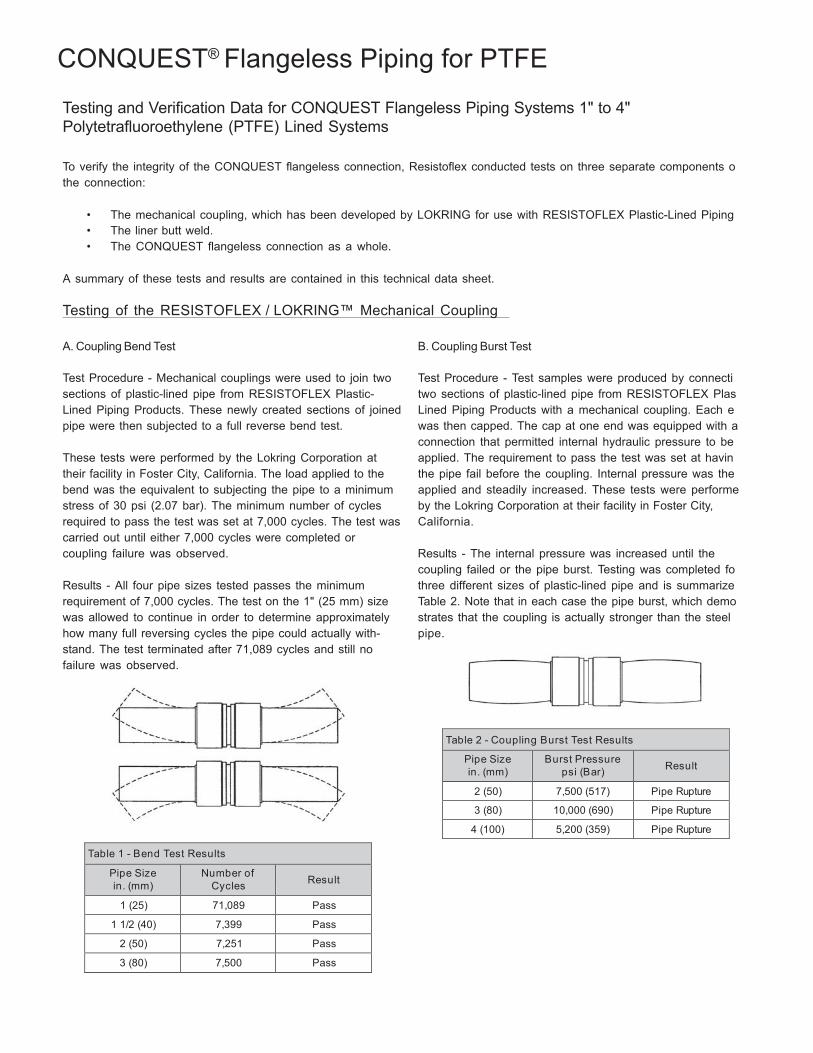
77
Table 2 - Coupling Burst Test Results
Pipe Size in. (mm)
Burst Pressure psi (Bar)
Result
2 (50) 7,500 (517) Pipe Rupture
3 (80) 10,000 (690) Pipe Rupture
4 (100) 5,200 (359) Pipe Rupture
CONQUEST® Flangeless Piping for PTFE
Testing and Verification Data for CONQUEST Flangeless Piping Systems 1" to 4" Polytetrafluoroethylene (PTFE) Lined Systems
To verify the integrity of the CONQUEST flangeless connection, Resistoflex conducted tests on three separate components o the connection:
• The mechanical coupling, which has been developed by LOKRING for use with RESISTOFLEX Plastic-Lined Piping • The liner butt weld. • The CONQUEST flangeless connection as a whole.
A summary of these tests and results are contained in this technical data sheet.
Testing of the RESISTOFLEX / LOKRING™ Mechanical Coupling
A. Coupling Bend Test
Test Procedure - Mechanical couplings were used to join two sections of plastic-lined pipe from RESISTOFLEX Plastic- Lined Piping Products. These newly created sections of joined pipe were then subjected to a full reverse bend test.
These tests were performed by the Lokring Corporation at their facility in Foster City, California. The load applied to the bend was the equivalent to subjecting the pipe to a minimum stress of 30 psi (2.07 bar). The minimum number of cycles required to pass the test was set at 7,000 cycles. The test was carried out until either 7,000 cycles were completed or coupling failure was observed.
Results - All four pipe sizes tested passes the minimum requirement of 7,000 cycles. The test on the 1" (25 mm) size was allowed to continue in order to determine approximately how many full reversing cycles the pipe could actually with- stand. The test terminated after 71,089 cycles and still no failure was observed.
B. Coupling Burst Test
Test Procedure - Test samples were produced by connecti two sections of plastic-lined pipe from RESISTOFLEX Plas Lined Piping Products with a mechanical coupling. Each e was then capped. The cap at one end was equipped with a connection that permitted internal hydraulic pressure to be applied. The requirement to pass the test was set at havin the pipe fail before the coupling. Internal pressure was the applied and steadily increased. These tests were performe by the Lokring Corporation at their facility in Foster City, California.
Results - The internal pressure was increased until the coupling failed or the pipe burst. Testing was completed fo three different sizes of plastic-lined pipe and is summarize Table 2. Note that in each case the pipe burst, which demo strates that the coupling is actually stronger than the steel pipe.
Table 1 - Bend Test Results
Pipe Size in. (mm)
Number of Cycles
Result
1 (25) 71,089 Pass
1 1/2 (40) 7,399 Pass
2 (50) 7,251 Pass
3 (80) 7,500 Pass
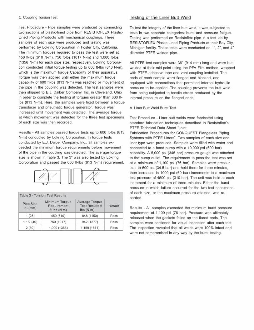
78
Table 3 - Torsion Test Results
Pipe Size in. (mm)
Minimum Torque Requirement ft-lbs (N-m)
Average Torque Test Results ft-lbs (N-m)
Result
1 (25) 450 (610) 848 (1150) Pass
1 1/2 (40) 750 (1017) 942 (1277) Pass
2 (50) 1,000 (1356) 1,159 (1571) Pass
C. Coupling Torsion Test
Test Procedure - Pipe samples were produced by connecting two sections of plastic-lined pipe from RESISTOFLEX Plastic- Lined Piping Products with mechanical couplings. Three samples of each size were produced and testing was performed by Lokring Corporation in Foster City, California. The minimum torques required to pass the test were set at 450 ft-lbs (610 N-m), 750 ft-lbs (1017 N-m) and 1,000 ft-lbs (1356 N-m) for each pipe size, respectively. Lokring Corpora- tion conducted initial torque testing up to 600 ft-lbs (813 N-m), which is the maximum torque Capability of their apparatus. Torque was then applied until either the maximum torque capability of 600 ft-lbs (813 N-m) was reached or movement of the pipe in the coupling was detected. The test samples were then shipped to E.J. Daiber Company, Inc. in Cleveland, Ohio in order to complete the testing at torques greater than 600 ft- lbs (813 N-m). Here, the samples were fixed between a torque transducer and pneumatic torque generator. Torque was increased until movement was detected. The average torque at which movement was detected for the three test specimens of each size was then recorded.
Results - All samples passed torque tests up to 600 ft-lbs (813 N-m) conducted by Lokring Corporation. In torque tests conducted by E.J. Daiber Company, Inc., all samples ex- ceeded the minimum torque requirements before movement of the pipe in the coupling was detected. The average torque size is shown in Table 3. The 3" was also tested by Lokring Corporation and passed the 600 ft-lbs (813 N-m) requirement.
Testing of the Liner Butt Weld
To test the integrity of the liner butt weld, it was subjected to tests in two separate categories: burst and pressure fatigue. Testing was performed on Resistoflex pipe in a test lab by RESISTOFLEX Plastic-Lined Piping Products at their Bay City, Michigan facility. These tests were conducted on 1", 2", and 4" diameter PTFE welded pipe.
All PTFE test samples were 36" (914 mm) long and were butt welded at their mid-point using the PFA Film method, wrapped with PTFE adhesive tape and vent coupling installed. The ends of each sample were flanged and blanked, and equipped with connections that permitted internal hydraulic pressure to be applied. The coupling prevents the butt weld from being subjected to tensile stress produced by the internal pressure on the flanged ends.
A. Liner Butt Weld Burst Test
Test Procedure - Liner butt welds were fabricated using standard fabrication techniques described in Resistoflex’s PTFE Technical Data Sheet “Joint Fabrication Procedures for CONQUEST Flangeless Piping Systems with PTFE Liners”. Two samples of each size and liner type were produced. Samples were filled with water and connected to a hand pump with a 10,000 psi (690 bar) capability. A 5,000 psi (345 bar) pressure gauge was attached to the pump outlet. The requirement to pass the test was set at a minimum of 1,100 psi (76 bar). Samples were pressur- ized to 500 psi (34.5 bar) and held there for three minutes, then increased in 1000 psi (69 bar) increments to a maximum test pressure of 4500 psi (310 bar). The unit was held at each increment for a minimum of three minutes. Either the burst pressure in which failure occurred for the two test specimens of each size, or the maximum pressure attained, was re- corded.
Results - All samples exceeded the minimum burst pressure requirement of 1,100 psi (76 bar). Pressure was ultimately released when the gaskets failed on the flared ends. The samples were sectioned for visual inspection after each test. The inspection revealed that all welds were 100% intact and were not compromised in any way by the burst testing.
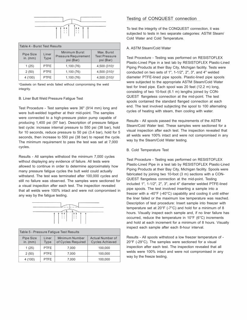
79
Table 5 - Pressure Fatigue Test Results
Pipe Size in. (mm)
Liner Type
Minimum Number of Cycles Required
Actual Number of Cycles Achieved
1 (25) PTFE 7,000 100,000
2 (50) PTFE 7,000 100,000
4 (100) PTFE 7,000 100,000
Table 4 - Burst Test Results
Pipe Size in. (mm)
Liner Type
Minimum Burst Pressure Requirement
psi (Bar)
Max. Burst Test Pressure
psi (Bar)
1 (25) PTFE 1,100 (76) 4,500 (310)†
2 (50) PTFE 1,100 (76) 4,500 (310)†
4 (100) PTFE 1,100 (76) 4,500 (310)†
†Gaskets on flared ends failed without compromising the weld integrity.
B. Liner Butt Weld Pressure Fatigue Test
Test Procedure - Test samples were 36" (914 mm) long and were butt-welded together at their mid-point. The samples were connected to a high-pressure piston pump capable of producing 1,400 psi (97 bar). Description of pressure fatigue test cycle: increase internal pressure to 550 psi (38 bar), hold for 10 seconds, reduce pressure to 50 psi (3.4 bar), hold for 5 seconds, then increase to 550 psi (38 bar) to repeat the cycle. The minimum requirement to pass the test was set at 7,000 cycles.
Results - All samples withstood the minimum 7,000 cycles without displaying any evidence of failure. All tests were allowed to continue in order to determine approximately how many pressure fatigue cycles the butt weld could actually withstand. The test was terminated after 100,000 cycles and still no failure was observed. The samples were sectioned for a visual inspection after each test. The inspection revealed that all welds were 100% intact and were not compromised in any way by the fatigue testing.
Testing of CONQUEST connection
To test the integrity of the CONQUEST connection, it was subjected to tests in two separate categories: ASTM Steam/ Cold Water and Cold Temperature.
A. ASTM Steam/Cold Water
Test Procedure - Testing was performed on RESISTOFLEX Plastic-Lined Pipe in a test lab by RESISTOFLEX Plastic-Lined Piping Products at their Bay City, Michigan facility. Tests were conducted on two sets of 1", 1-1/2", 2", 3", and 4" welded diameter PTFE-lined pipe spools. Plastic-lined pipe spools were subjected to the appropriate ASTM Steam/Cold Water test for lined pipe. Each spool was 20 feet (12.2 m) long, consisting of two 10-foot (6.1 m) lengths joined by CON- QUEST flangeless connection at the mid-point. The test spools contained the standard flanged connection at each end. The test involved subjecting the spool to 100 alternating cycles of heating with steam, then cooling with water.
Results - All spools passed the requirements of the ASTM Steam/Cold Water test. These samples were sectioned for a visual inspection after each test. The inspection revealed that all welds were 100% intact and were not compromised in any way by the Steam/Cold Water testing.
B. Cold Temperature Test
Test Procedure - Testing was performed on RESISTOFLEX Plastic-Lined Pipe in a test lab by RESISTOFLEX Plastic-Lined Piping Products at their Bay City, Michigan facility. Spools were fabricated by joining two 10-foot (3 m) sections with a CON- QUEST flangeless connection at the mid-point. Testing included 1", 1-1/2", 2", 3", and 4" diameter welded PTFE-lined pipe spools. The test involved inserting a sample into a freezer with a -40°F (-40°C) capability and cooling it until either the liner failed or the maximum low temperature was reached. Description of test procedure: Insert sample into freezer with temperature set at 20°F (-7°C) and hold for a minimum of 8 hours. Visually inspect each sample and, if no liner failure has occurred, reduce the temperature in 10°F (6°C) increments and hold at each increment for a minimum of 8 hours. Visually inspect each sample after each 8-hour interval.
Results - All spools withstood a low freezer temperature of - 20°F (-29°C). The samples were sectioned for a visual inspection after each test. The inspection revealed that all welds were 100% intact and were not compromised in any way by the freeze testing.
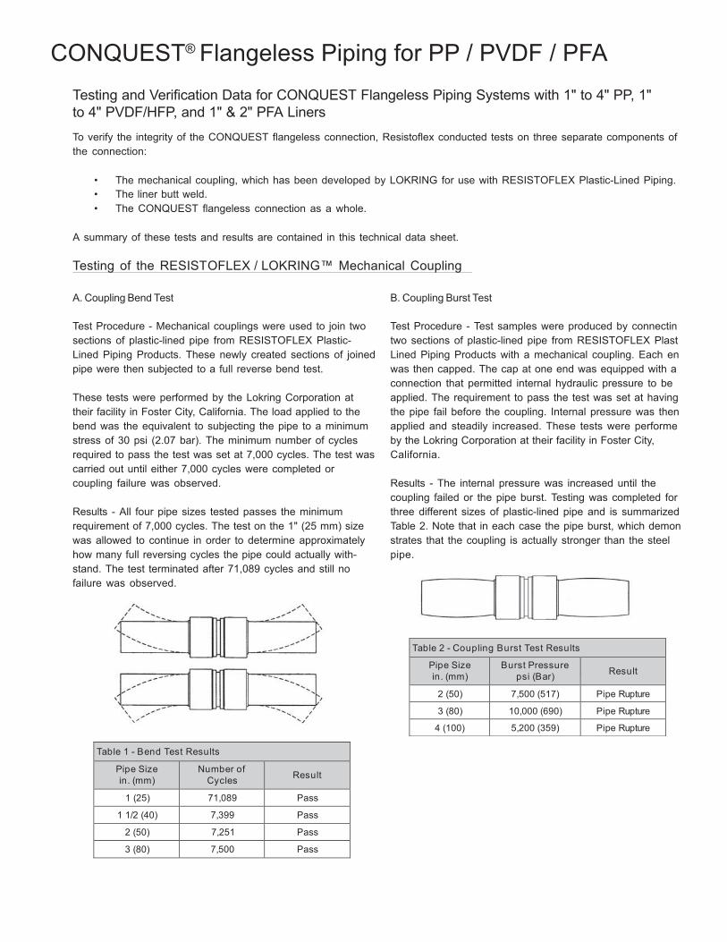
80
Table 2 - Coupling Burst Test Results
Pipe Size in. (mm)
Burst Pressure psi (Bar)
Result
2 (50) 7,500 (517) Pipe Rupture
3 (80) 10,000 (690) Pipe Rupture
4 (100) 5,200 (359) Pipe Rupture
CONQUEST® Flangeless Piping for PP / PVDF / PFA
Testing and Verification Data for CONQUEST Flangeless Piping Systems with 1" to 4" PP, 1" to 4" PVDF/HFP, and 1" & 2" PFA Liners
To verify the integrity of the CONQUEST flangeless connection, Resistoflex conducted tests on three separate components of the connection:
• The mechanical coupling, which has been developed by LOKRING for use with RESISTOFLEX Plastic-Lined Piping. • The liner butt weld. • The CONQUEST flangeless connection as a whole.
A summary of these tests and results are contained in this technical data sheet.
Testing of the RESISTOFLEX / LOKRING™ Mechanical Coupling
A. Coupling Bend Test
Test Procedure - Mechanical couplings were used to join two sections of plastic-lined pipe from RESISTOFLEX Plastic- Lined Piping Products. These newly created sections of joined pipe were then subjected to a full reverse bend test.
These tests were performed by the Lokring Corporation at their facility in Foster City, California. The load applied to the bend was the equivalent to subjecting the pipe to a minimum stress of 30 psi (2.07 bar). The minimum number of cycles required to pass the test was set at 7,000 cycles. The test was carried out until either 7,000 cycles were completed or coupling failure was observed.
Results - All four pipe sizes tested passes the minimum requirement of 7,000 cycles. The test on the 1" (25 mm) size was allowed to continue in order to determine approximately how many full reversing cycles the pipe could actually with- stand. The test terminated after 71,089 cycles and still no failure was observed.
B. Coupling Burst Test
Test Procedure - Test samples were produced by connectin two sections of plastic-lined pipe from RESISTOFLEX Plast Lined Piping Products with a mechanical coupling. Each en was then capped. The cap at one end was equipped with a connection that permitted internal hydraulic pressure to be applied. The requirement to pass the test was set at having the pipe fail before the coupling. Internal pressure was then applied and steadily increased. These tests were performe by the Lokring Corporation at their facility in Foster City, California.
Results - The internal pressure was increased until the coupling failed or the pipe burst. Testing was completed for three different sizes of plastic-lined pipe and is summarized Table 2. Note that in each case the pipe burst, which demon strates that the coupling is actually stronger than the steel pipe.
Table 1 - Bend Test Results
Pipe Size in. (mm)
Number of Cycles
Result
1 (25) 71,089 Pass
1 1/2 (40) 7,399 Pass
2 (50) 7,251 Pass
3 (80) 7,500 Pass
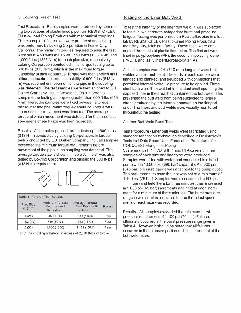
81
C. Coupling Torsion Test
Test Procedure - Pipe samples were produced by connect- ing two sections of plastic-lined pipe from RESISTOFLEX Plastic-Lined Piping Products with mechanical couplings. Three samples of each size were produced and testing was performed by Lokring Corporation in Foster City, California. The minimum torques required to pass the test were set at 450 ft-lbs (610 N-m), 750 ft-lbs (1017 N-m) and 1,000 ft-lbs (1356 N-m) for each pipe size, respectively. Lokring Corporation conducted initial torque testing up to 600 ft-lbs (813 N-m), which is the maximum torque Capability of their apparatus. Torque was then applied until either the maximum torque capability of 600 ft-lbs (813 N- m) was reached or movement of the pipe in the coupling was detected. The test samples were then shipped to E.J. Daiber Company, Inc. in Cleveland, Ohio in order to complete the testing at torques greater than 600 ft-lbs (813 N-m). Here, the samples were fixed between a torque transducer and pneumatic torque generator. Torque was increased until movement was detected. The average torque at which movement was detected for the three test specimens of each size was then recorded.
Results - All samples passed torque tests up to 600 ft-lbs (813 N-m) conducted by Lokring Corporation. In torque tests conducted by E.J. Daiber Company, Inc., all samples exceeded the minimum torque requirements before movement of the pipe in the coupling was detected. The average torque size is shown in Table 3. The 3" was also tested by Lokring Corporation and passed the 600 ft-lbs (813 N-m) requirement.
Table 3 - Torsion Test Results
Pipe Size in. (mm)
Minimum Torque Requirement ft-lbs (N-m)
Average Torque Test Results ft-lbs (N-m)
Result
1 (25) 450 (610) 848 (1150) Pass
1 1/2 (40) 750 (1017) 942 (1277) Pass
2 (50) 1,000 (1356) 1,159 (1571) Pass
For 3” the coupling withstood in excess of 2,000 ft-lbs of torque.
Testing of the Liner Butt Weld
To test the integrity of the liner butt weld, it was subjected to tests in two separate categories: burst and pressure fatigue. Testing was performed on Resistoflex pipe in a test lab by RESISTOFLEX Plastic-Lined Piping Products at their Bay City, Michigan facility. These tests were con- ducted three sets of plastic-lined pipe. The first set was lined in polypropylene (PP), the second in polyvinylidene (PVDF), and lastly in perfluoroalkoxy (PFA).
All test samples were 24" (610 mm) long and were butt welded at their mid-point. The ends of each sample were flanged and blanked, and equipped with connections that permitted internal hydraulic pressure to be applied. Three steel bars were then welded to the steel shell spanning the exposed liner in the area that contained the butt weld. This prevented the butt weld from being subjected to tensile stress produced by the internal pressure on the flanged ends. The liners and butt-welds were visually monitored throughout the testing.
A. Liner Butt Weld Burst Test
Test Procedure - Liner butt welds were fabricated using standard fabrication techniques described in Resistoflex’s Technical Data Sheet “Joint Fabrication Procedures for CONQUEST Flangeless Piping Systems with PP, PVDF/HFP, and PFA-Liners”. Three samples of each size and liner type were produced. Samples were filled with water and connected to a hand pump witha 10,000 psi (690 bar) capability. A 5,000 psi (345 bar) pressure gauge was attached to the pump outlet. The requirement to pass the test was set at a minimum of 1,100 psi (76 bar). Samples were pressurized to 500 psi bar) and held there for three minutes, then increased in 1,000 psi (69 bar) increments and held at each incre- ment for a minimum of three minutes. The burst pressure range in which failure occurred for the three test speci- mens of each size was recorded.
Results - All samples exceeded the minimum burst pressure requirement of 1,100 psi (76 bar). Failures ultimately occurred in the burst pressure range given in Table 4. However, it should be noted that all failures occurred in the exposed portion of the liner and not at the butt weld faces.
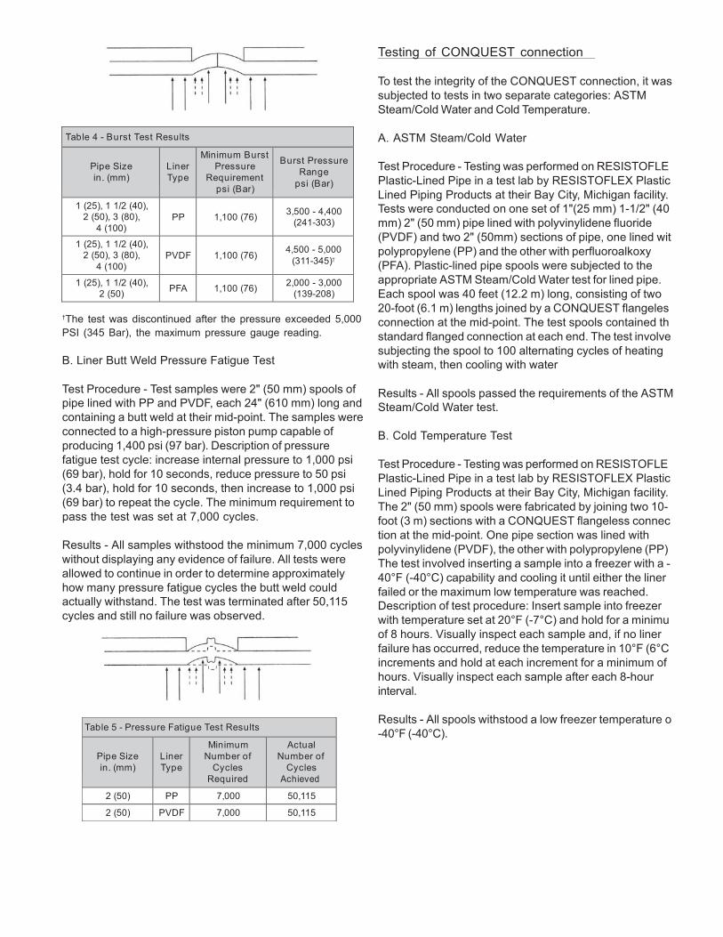
82
Table 5 - Pressure Fatigue Test Results
Pipe Size in. (mm)
Liner Type
Minimum Number of
Cycles Required
Actual Number of
Cycles Achieved
2 (50) PP 7,000 50,115
2 (50) PVDF 7,000 50,115
Table 4 - Burst Test Results
Pipe Size in. (mm)
Liner Type
Minimum Burst Pressure
Requirement psi (Bar)
Burst Pressure
Range psi (Bar)
1 (25), 1 1/2 (40), 2 (50), 3 (80),
4 (100)
PP
1,100 (76)
3,500 - 4,400
(241-303)
1 (25), 1 1/2 (40), 2 (50), 3 (80),
4 (100)
PVDF
1,100 (76)
4,500 - 5,000
(311-345)†
1 (25), 1 1/2 (40), 2 (50)
PFA
1,100 (76) 2,000 - 3,000
(139-208)
†The test was discontinued after the pressure exceeded 5,000 PSI (345 Bar), the maximum pressure gauge reading.
B. Liner Butt Weld Pressure Fatigue Test
Test Procedure - Test samples were 2" (50 mm) spools of pipe lined with PP and PVDF, each 24" (610 mm) long and containing a butt weld at their mid-point. The samples were connected to a high-pressure piston pump capable of producing 1,400 psi (97 bar). Description of pressure fatigue test cycle: increase internal pressure to 1,000 psi (69 bar), hold for 10 seconds, reduce pressure to 50 psi (3.4 bar), hold for 10 seconds, then increase to 1,000 psi (69 bar) to repeat the cycle. The minimum requirement to pass the test was set at 7,000 cycles.
Results - All samples withstood the minimum 7,000 cycles without displaying any evidence of failure. All tests were allowed to continue in order to determine approximately how many pressure fatigue cycles the butt weld could actually withstand. The test was terminated after 50,115 cycles and still no failure was observed.
Testing of CONQUEST connection
To test the integrity of the CONQUEST connection, it was subjected to tests in two separate categories: ASTM Steam/Cold Water and Cold Temperature.
A. ASTM Steam/Cold Water
Test Procedure - Testing was performed on RESISTOFLE Plastic-Lined Pipe in a test lab by RESISTOFLEX Plastic Lined Piping Products at their Bay City, Michigan facility. Tests were conducted on one set of 1"(25 mm) 1-1/2" (40 mm) 2" (50 mm) pipe lined with polyvinylidene fluoride (PVDF) and two 2" (50mm) sections of pipe, one lined wit polypropylene (PP) and the other with perfluoroalkoxy (PFA). Plastic-lined pipe spools were subjected to the appropriate ASTM Steam/Cold Water test for lined pipe. Each spool was 40 feet (12.2 m) long, consisting of two 20-foot (6.1 m) lengths joined by a CONQUEST flangeles connection at the mid-point. The test spools contained th standard flanged connection at each end. The test involve subjecting the spool to 100 alternating cycles of heating with steam, then cooling with water
Results - All spools passed the requirements of the ASTM Steam/Cold Water test.
B. Cold Temperature Test
Test Procedure - Testing was performed on RESISTOFLE Plastic-Lined Pipe in a test lab by RESISTOFLEX Plastic Lined Piping Products at their Bay City, Michigan facility. The 2" (50 mm) spools were fabricated by joining two 10- foot (3 m) sections with a CONQUEST flangeless connec tion at the mid-point. One pipe section was lined with polyvinylidene (PVDF), the other with polypropylene (PP) The test involved inserting a sample into a freezer with a - 40°F (-40°C) capability and cooling it until either the liner failed or the maximum low temperature was reached. Description of test procedure: Insert sample into freezer with temperature set at 20°F (-7°C) and hold for a minimu of 8 hours. Visually inspect each sample and, if no liner failure has occurred, reduce the temperature in 10°F (6°C increments and hold at each increment for a minimum of hours. Visually inspect each sample after each 8-hour interval.
Results - All spools withstood a low freezer temperature o -40°F (-40°C).
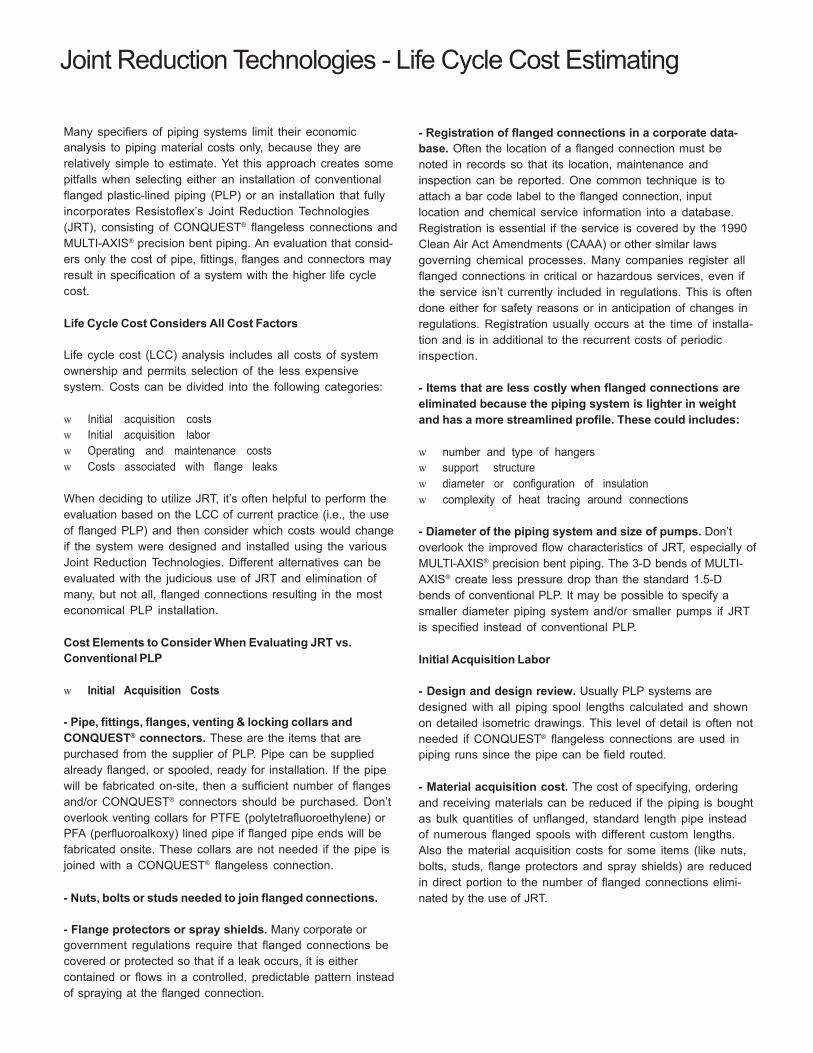
83
Joint Reduction Technologies - Life Cycle Cost Estimating
Many specifiers of piping systems limit their economic analysis to piping material costs only, because they are relatively simple to estimate. Yet this approach creates some pitfalls when selecting either an installation of conventional flanged plastic-lined piping (PLP) or an installation that fully incorporates Resistoflex’s Joint Reduction Technologies (JRT), consisting of CONQUEST® flangeless connections and MULTI-AXIS® precision bent piping. An evaluation that consid- ers only the cost of pipe, fittings, flanges and connectors may result in specification of a system with the higher life cycle cost.
Life Cycle Cost Considers All Cost Factors
Life cycle cost (LCC) analysis includes all costs of system ownership and permits selection of the less expensive system. Costs can be divided into the following categories:
w Initial acquisition costs w Initial acquisition labor w Operating and maintenance costs w Costs associated with flange leaks
When deciding to utilize JRT, it’s often helpful to perform the evaluation based on the LCC of current practice (i.e., the use of flanged PLP) and then consider which costs would change if the system were designed and installed using the various Joint Reduction Technologies. Different alternatives can be evaluated with the judicious use of JRT and elimination of many, but not all, flanged connections resulting in the most economical PLP installation.
Cost Elements to Consider When Evaluating JRT vs. Conventional PLP
w Initial Acquisition Costs
- Pipe, fittings, flanges, venting & locking collars and CONQUEST® connectors. These are the items that are purchased from the supplier of PLP. Pipe can be supplied already flanged, or spooled, ready for installation. If the pipe will be fabricated on-site, then a sufficient number of flanges and/or CONQUEST® connectors should be purchased. Don’t overlook venting collars for PTFE (polytetrafluoroethylene) or PFA (perfluoroalkoxy) lined pipe if flanged pipe ends will be fabricated onsite. These collars are not needed if the pipe is joined with a CONQUEST® flangeless connection.
- Nuts, bolts or studs needed to join flanged connections.
- Flange protectors or spray shields. Many corporate or government regulations require that flanged connections be covered or protected so that if a leak occurs, it is either contained or flows in a controlled, predictable pattern instead of spraying at the flanged connection.
- Registration of flanged connections in a corporate data- base. Often the location of a flanged connection must be noted in records so that its location, maintenance and inspection can be reported. One common technique is to attach a bar code label to the flanged connection, input location and chemical service information into a database. Registration is essential if the service is covered by the 1990 Clean Air Act Amendments (CAAA) or other similar laws governing chemical processes. Many companies register all flanged connections in critical or hazardous services, even if the service isn’t currently included in regulations. This is often done either for safety reasons or in anticipation of changes in regulations. Registration usually occurs at the time of installa- tion and is in additional to the recurrent costs of periodic inspection.
- Items that are less costly when flanged connections are eliminated because the piping system is lighter in weight and has a more streamlined profile. These could includes:
w number and type of hangers w support structure w diameter or configuration of insulation w complexity of heat tracing around connections
- Diameter of the piping system and size of pumps. Don’t overlook the improved flow characteristics of JRT, especially of MULTI-AXIS® precision bent piping. The 3-D bends of MULTI- AXIS® create less pressure drop than the standard 1.5-D bends of conventional PLP. It may be possible to specify a smaller diameter piping system and/or smaller pumps if JRT is specified instead of conventional PLP.
Initial Acquisition Labor
- Design and design review. Usually PLP systems are designed with all piping spool lengths calculated and shown on detailed isometric drawings. This level of detail is often not needed if CONQUEST® flangeless connections are used in piping runs since the pipe can be field routed.
- Material acquisition cost. The cost of specifying, ordering and receiving materials can be reduced if the piping is bought as bulk quantities of unflanged, standard length pipe instead of numerous flanged spools with different custom lengths. Also the material acquisition costs for some items (like nuts, bolts, studs, flange protectors and spray shields) are reduced in direct portion to the number of flanged connections elimi- nated by the use of JRT.
84
Joint Reduction Technologies - Life Cycle Cost Estimating
- &IELD FABRICATION OF CUSTOM LENGTH PIPE. 4HE PROCESS OF 0,0 CUSTOM SPOOL FABRICATION INCLUDES CUTTING AND THREADING THE PIPE, INSTALLING AND ALIGNING THE FLANGE, INSTALLING THE VENTING OR LOCKING COLLAR, HEATING THE PLASTIC STUB, FLARING THE PLASTIC FACE, COOLING AND REMOVING THE FLARING DIE AND INSTALLING A PROTECTIVE WOODEN COVER OVER THE FLARED FACE. 4HIS PROCESS CAN BE TIME- CONSUMING AND QUALITY DIFFICULT TO CONTROL IF PERFORMED ON-SITE BY PERSONNEL WHO FABRICATE 0,0 ON AN INFREQUENT BASIS. /FTEN CUSTOM SPOOLS ARE FABRICATED AT THE FACTORY OR BY NEARBY STOCKING DISTRIBUTORS WHO HAVE FULLY EQUIPPED SHOPS AND CERTIFIED PERSONNEL THAT FABRICATE 0,0 ROUTINELY. )F CONVENTIONAL 0,0 IS FABRICATED AT THE FACTORY OR BY A DISTRIBUTOR, THEN THE COST WILL BE PART OF THE PURCHASE PRICE QUOTED BY THE SUPPLIER OF THE FABRICATED PIPE. 5NDERSTANDABLY, FLANGED AND FABRICATED SPOOLS ARE MORE EXPENSIVE THAN PLAIN-END 0,0.
- #OST OF INSTALLATION. 4HIS INCLUDES THE COST OF INSTALLING THE PIPING SYSTEM AND THE ASSOCIATED NUTS, BOLTS, STUDS, FLANGE PROTECTORS AND SPRAY SHIELDS WITH CONVENTIONAL 0,0 OR THE COST OF FABRICATING A #/.15%34 ¸ CONNECTION WHEN THE METHOD IS USED TO CREATE A JOINT.
- -ISCELLANEOUS LABOR COST SAVINGS. "E SURE TO INCLUDE LABOR COST SAVINGS IF THE USE OF LIGHTER WEIGTH, STREAMLINED *24 PIPING PERMITS A REDUCTION IN THE NUMBER OF HANGERS AND SUPPORTS AND IF THE ELIMINATION OF FLANGED CONNECTIONS SPEEDS UP THE INSTALLATION OF INSULATION AND HEAT TRACING. !LSO, THE TIME REQUIRED FOR PAINTING CAN BE REDUCED WHEN FLANGED CONNEC- TIONS ARE ELIMINATED. )F INSTALLATION TIME IS REDUCED, THEN IT'S OFTEN POSSIBLE TO REDUCE THE TIME REQUIRED FOR RENTAL OR RECHARGE OF EQUIPMENT LIKE MAN-LIFTS.
- 3TART-UP COSTS. 4HIS INCLUDES THE TIME TO HYDROTEST THE PIPING SYSTEM AND PERFORM THE RECOMMENDED RETORQING OF BOLTS AFTER 24 HOURS OF OPERATION. 7HEN FLANGED CONNECTIONS ARE ELIMI- NATED, THE START-UP TIME CAN BE SUBSTANTIALLY REDUCED. 4HIS MEANS THAT THE SYSTEM IS OPERATIONAL SOONER AND THE PROCESS IS OUT OF COMMISSION FOR A SHORTER PERIOD OF TIME.
/PERATING AND MAINTENANCE COSTS
- -ONITORING AND ASSOCIATED PAPERWORK. 'OVERNMENT OR CORPORATE REGULATIONS MAY REQUIRE THE PERIODIC MONITORING OF FLANGED CONNECTION FOR LEAKS AND RECORDS OF THAT MONITORING ACTIVITY. )F A SERVICE IS LISTED IN THE 1990 #!!!, THEN THE CONNEC- TION MUST BE hSNIFFEDv FOR FUGITIVE EMISSIONS AND DETAILED RECORDS MAINTAINED FOR SUBMITTAL TO THE GOVERNMENT. 4HE MONITORING FREQUENCY RANGES FROM EVERY SIX MONTHS TO BIANNUALLY, DEPENDING UPON THE SERVICE AND HISTORY OF THE SITE. %VEN IF REGULATIONS DON'T REQUIRE MONITORING, IT'S STILL GOOD CHEMICAL PLANT OPERATIONS PRACTICE TO VISUALLY INSPECT FLANGED CONNECTIONS PERIODICALLY FOR SIGNS OF LEAKS OR EMISSIONS.
- 0ERIODIC RETORQUING OF FLANGE BOLTS. )T'S COMMON FOR FLANGE BOLT TORQUES TO BE CHECKED AND BOLTS TIGHTENED, IF NEEDED, ON A PERIODIC BASIS. /FTEN THIS IS DONE SEMI-ANNUALLY OR ANNUALLY DEPENDING UPON THE THERMAL CYCLING HISTORY OF THE PIPING. 4HIS RETORQUING ISN'T NEEDED WHEN FLANGED CONNECTIONS ARE ELIMINATED THROUGH INSTALLATION OF *24.
- #LEANING COSTS. #ONSIDER THE COST DIFFERENCE IN BATCH-TO- BATCH CLEANING OF CONVENTIONAL 0,0 VS. *24. )N SOME BATCH PROCESSES THIS CAN BE A SAVINGS, PARTICULARLY WHEN DIRECTIONAL CHANGES IN THE PIPING ARE CREATED WITH -5,4)-!8)3 ¸ PIPING INSTEAD OF WITH CONVENTIONAL FLANGED ELBOWS, WHICH HAVE A DISCONTINUITY OR CREVICE AT THE FLANGED CONNECTION.
#OSTS ASSOCIATED WITH FLANGED LEAKS
- 5NUSED CAPACITY. #ONSIDER THE LIKELIHOOD OF PLANT OUTAGES DUE TO FLANGE LEAKS AND THE COST OF PRODUCTION THAT IS LOST WHEN THE PLANT ISN'T OPERATING.
- /UT-OF-SPEC PRODUCT. &LANGE LEAKS CAN CREATE A SUDDEN AND UNEXPECTED PLANT OUTAGE RESULTING IN THE PRODUCTION OF OUT-OF- SPEC PRODUCT.
- 3AFETY ISSUES. 4HE hCOSTv IS DIFFICULT TO ESTIMATE BUT CAN BE A TANGIBLE CONCERN FOR SOME CHEMICAL SERVICES AND/OR SOME PIPING SYSTEM LOCATIONS. 4HIS COULD INCLUDE DIRECT INJURY TO WORKERS AND PASSERS-BY AND INDIRECT ISSUES SUCH AS EVACUA- TION OF THE PROCESS SITE AND ADJACENT AREAS.
- 2EPORTING REQUIREMENTS. 'OVERNMENT OR CORPORATE REGULA- TIONS CAN REQUIRE LENGTHY AND TIME-CONSUMING REPORTS AND INVESTIGATIONS IN THE EVENT OF FLANGE LEAKS. 4HE DIRECT AND INDIRECT COSTS OF THESE REPORTS SHOULDN'T BE OVERLOOKED.
%XAMPLE OF ,IFE #YCLE #OST %STIMATING !NALYSIS
#ONSIDER A PIPING SYSTEM THAT WAS RECENTLY INSTALLED WITH EXTENSIVE USE OF *24. 4HE SYSTEM CONSISTS OF 2-IN DIAMETER (50 MM ..".) 06$&-LINED PIPING THAT WAS INSTALLED IN AN EXISTING, OVERHEAD PIPE RACK TO REPLACE A CONVENTIONAL 0,0 SYSTEM THAT HAD REACHED THE END OF ITS USEFUL LIFE OF SEVERAL DECADES. 4HE CONVENTIONAL SYSTEM CONSISTS OF 670 FT (204 M) OF PIPING, TEN DIRECTIONAL CHANGES FOR ROUTING THE THERMAL EXPANSION PURPOSES AND TWO TEES INSTALLED AS hSTAND-PIPESv TO REDUCE THE EFFECT OF WATER HAMMER. "Y SPECIFYING *24, ALL THE FLANGE CONNECTIONS, EXCEPT FOR THE FIRST AND LAST CONNECTIONS. )N *24, THE SYSTEM CONSISTS OF 620 FT OF STRAIGHT-RUN PIPING, THREE PIECES OF -5,4)-!8)3 ¸ PRECISION-BENT PIPING, TWO #/.- 15%34 ¸ FLANGELESS TEES AND THIRTY-SEVEN #/.15%34 ¸
CONNECTIONS. 4HE SYSTEM IS DEPICTED IN THE ISOMETRIC DRAWING. #OSTS ARE ESTIMATED USING 1995 DATA FOR THE UPPER MID-WEST AND LISTED IS 5.3. DOLLARS.
85
Initial Acquisition Labor Savings
- Design, design review and material acquisition costs. Since this system represents an initial JRT installation at this location, the specifiers decided that the design, review and acquisition of the system would be no different with either design. After the installation, they report that the project went very “smoothly” and they can anticipate savings in design, review and acquisition of future JRT installations.
- Elimination of field fabrication of flanged custom length pipe. It takes about 1.15 hr to completely cut, thread, flange, flare and block the two ends of a 2" PVDF-lined spool. There are thirty-seven spools in the conventional flanged system design, representing a total fabrication time of 42.55 hours. It takes about 0.6 hours to cut, align, trim, butt-fusion weld and install a CONQUEST® connection. There are thirty-seven CONQUEST® connections in the system, with a total installa- tion time of 22.2 hours.
- Cost of installation. It takes about 0.4 hr to install the nuts, bolts and flange shield of a 2" diameter connection. There are forty-nine flanged connections in the conventional design, for a total installation labor of 9.80 hours. The CONQUEST®
connections are installed during the fabrication process outlined above, so there is no additional installation time since there are no nuts, bolts or spray shields used.
- Start-up costs. It’s assumed that the cost to hydrotest the system would be identical for conventional piping and for a JRT system. However, the costs for hydrotesting of the conventional system would be higher if leaks occurred at the flanged connections and had to be corrected during the hydrotest. A leak occurring in a CONQUEST® connection during hydrotest would not be likely. These costs could be included based on previous experience at the site. However, the cost of the 24-hr retorqing of the flanged connections is tangible, at 0.2 hr per connection. With forty-nine flanged connections, there’s an additional 9.8 hrs needed to start up the conventional system. The conventional PLP system takes nearly fifty hours more to fabricate, install and start-up than the same system that fully incorporates JRT to eliminate flanged connections. At $50.00 per hour, the seemingly “less expen- sive” system is nearly $2500 more expensive to install and commission.
So, if both the initial acquisition costs and the initial acquisi- tion labor is considered, the total installed cost of the system that incorporates CONQUEST® flangeless joints and MULTI- AXIS® precision-bent piping is $3,800 less than the same system installed with conventional flanged plastic-lined piping. This savings increases if the operating and mainte- nance costs are also considered.
Operating and maintenance costs
- Annual monitoring and record keeping. It costs about $75.00 annually to monitor and record the testing of each flanged connection in a conventional PLP system. With forty- nine flanged connections, the system will cost an additional $3,675 per year to maintain.
- Annual retorquing. The cost to retorque each connection is about $10.00 per year, creating an additional $490 in annual operating costs not required to maintain a JRT system. In certain critical services, retorquing is required semi-annually or quarterly.
- Other costs. Leaks and shut-downs can be very expensive, yet each location will have to evaluate their annual cost potential based upon system configuration, location, process conditions and history. These costs should not be overlooked, but are beyond the scope of this study.
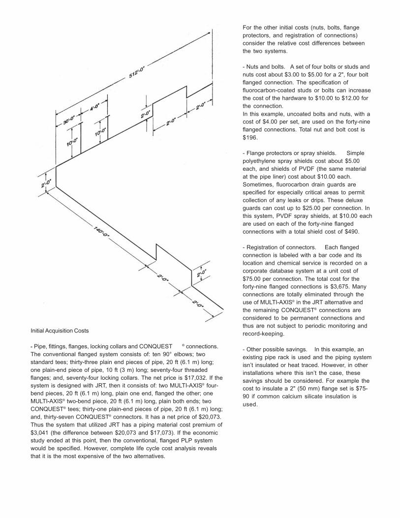
86
Initial Acquisition Costs
- Pipe, fittings, flanges, locking collars and CONQUEST ® connections. The conventional flanged system consists of: ten 90° elbows; two standard tees; thirty-three plain end pieces of pipe, 20 ft (6.1 m) long; one plain-end piece of pipe, 10 ft (3 m) long; seventy-four threaded flanges; and, seventy-four locking collars. The net price is $17,032. If the system is designed with JRT, then it consists of: two MULTI-AXIS® four- bend pieces, 20 ft (6.1 m) long, plain one end, flanged the other; one MULTI-AXIS® two-bend piece, 20 ft (6.1 m) long, plain both ends; two CONQUEST® tees; thirty-one plain-end pieces of pipe, 20 ft (6.1 m) long; and, thirty-seven CONQUEST® connectors. It has a net price of $20,073. Thus the system that utilized JRT has a piping material cost premium of $3,041 (the difference between $20,073 and $17,073). If the economic study ended at this point, then the conventional, flanged PLP system would be specified. However, complete life cycle cost analysis reveals that it is the most expensive of the two alternatives.
For the other initial costs (nuts, bolts, flange protectors, and registration of connections) consider the relative cost differences between the two systems.
- Nuts and bolts. A set of four bolts or studs and nuts cost about $3.00 to $5.00 for a 2", four bolt flanged connection. The specification of fluorocarbon-coated studs or bolts can increase the cost of the hardware to $10.00 to $12.00 for the connection. In this example, uncoated bolts and nuts, with a cost of $4.00 per set, are used on the forty-nine flanged connections. Total nut and bolt cost is $196.
- Flange protectors or spray shields. Simple polyethylene spray shields cost about $5.00 each, and shields of PVDF (the same material at the pipe liner) cost about $10.00 each. Sometimes, fluorocarbon drain guards are specified for especially critical areas to permit collection of any leaks or drips. These deluxe guards can cost up to $25.00 per connection. In this system, PVDF spray shields, at $10.00 each are used on each of the forty-nine flanged connections with a total shield cost of $490.
- Registration of connectors. Each flanged connection is labeled with a bar code and its location and chemical service is recorded on a corporate database system at a unit cost of $75.00 per connection. The total cost for the forty-nine flanged connections is $3,675. Many connections are totally eliminated through the use of MULTI-AXIS® in the JRT alternative and the remaining CONQUEST® connections are considered to be permanent connections and thus are not subject to periodic monitoring and record-keeping.
- Other possible savings. In this example, an existing pipe rack is used and the piping system isn’t insulated or heat traced. However, in other installations where this isn’t the case, these savings should be considered. For example the cost to insulate a 2" (50 mm) flange set is $75- 90 if common calcium silicate insulation is used.
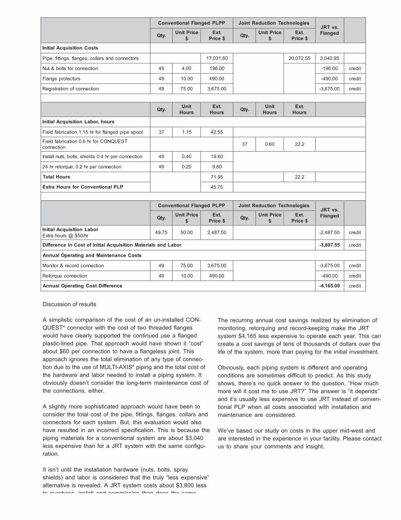
Conventional Flanged PLPP Joint Reduction Technologies JRT vs. Flanged
Qty. Unit Price $
Ext. Price $
Qty. Unit Price
$ Ext.
Price $
Initial Acquisition Costs Pipe, fittings, flanges, collars and connectors 17,031.60 20,072.55 3,040.95 Nut & bolts for connection 49 4.00 196.00 -196.00 credit
Flange protectors 49 10.00 490.00 -490.00 credit
Registration of connection 49 75.00 3,675.00 -3,675.00 credit
Qty. Unit Hours
Ext. Hours
Qty. Unit
Hours Ext.
Hours
Initial Acquisition Labor, hours Field fabrication 1.15 hr for flanged pipe spool 37 1.15 42.55 Field fabrication 0.6 hr for CONQUEST connection
37
0.60
22.2
Install nuts, bolts, shields 0.4 hr per connection 49 0.40 19.60 24 hr retorque, 0.2 hr per connection 49 0.20 9.80
Total Hours 71.95 22.2 Extra Hours for Conventional PLP 45.75 Conventional Flanged PLPP Joint Reduction Technologies
JRT vs. Flanged
Qty. Unit Price $
Ext. Price $
Qty. Unit Price
$ Ext.
Price $
Initial Acquisition Labor Extra hours @ $50/hr
49.75
50.00
2,487.50
-2,487.50
credit
Difference in Cost of Initial Acquisition Materials and Labor -3,807.55 credit
Annual Operating and Maintenance Costs
Monitor & record connection 49 75.00 3,675.00 -3,675.00 credit
Retorque connection 49 10.00 490.00 -490.00 credit
Annual Operating Cost Difference -4,165.00 credit
Discussion of results
A simplistic comparison of the cost of an un-installed CON- QUEST® connector with the cost of two threaded flanges would have clearly supported the continued use a flanged plastic-lined pipe. That approach would have shown it “cost” about $60 per connection to have a flangeless joint. This approach ignores the total elimination of any type of connec- tion due to the use of MULTI-AXIS® piping and the total cost of the hardware and labor needed to install a piping system. It obviously doesn’t consider the long-term maintenance cost of the connections, either.
A slightly more sophisticated approach would have been to consider the total cost of the pipe, fittings, flanges, collars and connectors for each system. But, this evaluation would also have resulted in an incorrect specification. This is because the piping materials for a conventional system are about $3,040 less expensive than for a JRT system with the same configu- ration.
It isn’t until the installation hardware (nuts, bolts, spray shields) and labor is considered that the truly “less expensive” alternative is revealed. A JRT system costs about $3,800 less to purchase, install and commission than does the same system in conventional flanged PLP.
The recurring annual cost savings realized by elimination of monitoring, retorquing and record-keeping make the JRT system $4,165 less expensive to operate each year. This can create a cost savings of tens of thousands of dollars over the life of the system, more than paying for the initial investment.
Obviously, each piping system is different and operating conditions are sometimes difficult to predict. As this study shows, there’s no quick answer to the question, “How much more will it cost me to use JRT?” The answer is “it depends” and it’s usually less expensive to use JRT instead of conven- tional PLP when all costs associated with installation and maintenance are considered.
We’ve based our study on costs in the upper mid-west and are interested in the experience in your facility. Please contact us to share your comments and insight.
87
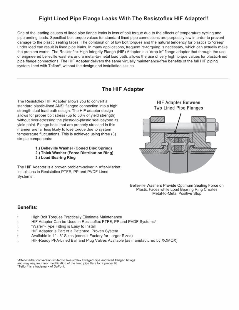
88
Fight Lined Pipe Flange Leaks With The Resistoflex HIF Adapter!!
One of the leading causes of lined pipe flange leaks is loss of bolt torque due to the effects of temperature cycling and pipe ending loads. Specified bolt torque values for standard lined pipe connections are purposely low in order to prevent damage to the plastic sealing faces. The combination of low bolt torques and the natural tendency for plastics to “creep” under load can result in lined pipe leaks. In many applications, frequent re-torquing is necessary, which can actually make the problem worse. The Resistoflex High Integrity Flange (HIF) Adapter is a “drop-in” flange adapter that through the use of engineered belleville washers and a metal-to-metal load path, allows the use of very high torque values for plastic-lined pipe flange connections. The HIF Adapter delivers the same virtually maintenance-free benefits of the full HIF piping system lined with Teflon®, without the design and installation issues.
The HIF Adapter
The Resistoflex HIF Adapter allows you to convert a standard plastic-lined ANSI flanged connection into a high strength dual-load path design. The HIF adapter design allows for proper bolt stress (up to 50% of yield strength) without over-stressing the plastic-to-plastic seal beyond its yield point. Flange bolts that are properly stressed in this manner are far less likely to lose torque due to system temperature fluctuations. This is achieved using three (3) simple components:
1.) Belleville Washer (Coned Disc Spring) 2.) Thick Washer (Force Distribution Ring) 3.) Load Bearing Ring
The HIF Adapter is a proven problem-solver in After-Market Installtions in Resistoflex PTFE, PP and PVDF Lined Systems1.
Belleville Washers Provide Optimum Sealing Force on Plastic Faces while Load Bearing Ring Creates
Metal-to-Metal Positive Stop
Benefits:
t High Bolt Torques Practically Eliminate Maintenance t HIF Adapter Can be Used in Resistoflex PTFE, PP and PVDF Systems1
t “Wafer”-Type Fitting is Easy to Install t HIF Adapter is Part of a Patented, Proven System t Available in 1” - 8” Sizes (consult Factory for Larger Sizes) t HIF-Ready PFA-Lined Ball and Plug Valves Available (as manufactured by XOMOX)
1After-market conversion limited to Resistoflex Swaged pipe and fixed flanged fittings and may require minor modification of the lined pipe flare for a proper fit. *Teflon® is a trademark of DuPont.
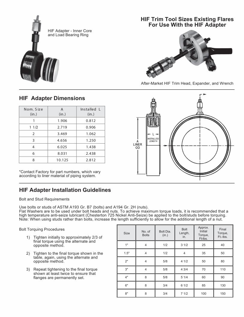
89
Size
No. of Bolts
Bolt Dia.
(in.)
Bolt Length,
in.
Approx. Initial
Torque, Ft-lbs.
Final Torque, Ft.-lbs.
1"
4
1/2
3 1/2
25
40
1.5"
4
1/2
4
35
50
2"
4
5/8
4 1/2
50
80
3" 4 5/8 4 3/4 70 110
4" 8 5/8 5 1/4 60 90
6" 8 3/4 6 1/2 85 130
8"
8
3/4
7 1/2
100
150
HIF Adapter - Inner Core and Load Bearing Ring
HIF Adapter Dimensions
N om. S iz e (in.)
A (in.)
Ins talled L (in.)
1 1.906 0.812
1 1/2 2.719 0.906
2 3.469 1.062
3 4.656 1.250
4 6.025 1.438
6 8.031 2.438
8 10.125 2.812 *Contact Factory for part numbers, which vary according to liner material of piping system.
HIF Adapter Installation Guidelines
Bolt and Stud Requirements
HIF Trim Tool Sizes Existing Flares For Use With the HIF Adapter
After-Market HIF Trim Head, Expander, and Wrench
Use bolts or studs of ASTM A193 Gr. B7 (bolts) and A194 Gr. 2H (nuts). Flat Washers are to be used under bolt heads and nuts. To achieve maximum torque loads, it is recommended that a high temperature anti-seize lubricant (Chesterton 725 Nickel Anti-Seize) be applied to the bolt/studs before torquing. Note: When using studs rather than bolts, increase the length sufficiently to allow for the additional length of a nut. Bolt Torquing Procedures
1) Tighten initially to approximately 2/3 of
final torque using the alternate and opposite method.
2) Tighten to the final torque shown in the
table, again, using the alternate and opposite method.
3) Repeat tightening to the final torque
shown at least twice to ensure that flanges are permanently set.
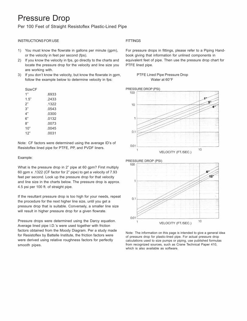
90
Pressure Drop Per 100 Feet of Straight Resistoflex Plastic-Lined Pipe
INSTRUCTIONS FOR USE
1) You must know the flowrate in gallons per minute (gpm), or the velocity in feet per second (fps).
2) If you know the velocity in fps, go directly to the charts and locate the pressure drop for the velocity and line size you are working with.
3) If you don’t know the velocity, but know the flowrate in gpm, follow the example below to determine velocity in fps:
SizeCF 1” .6933 1.5” .2433 2” .1322 3” .0543 4” .0300 6” .0132 8” .0073 10” .0045 12” .0031
Note: CF factors were determined using the average ID’s of Resistoflex lined pipe for PTFE, PP, and PVDF liners.
Example:
What is the pressure drop in 2” pipe at 60 gpm? First multiply 60 gpm x .1322 (CF factor for 2” pipe) to get a velocity of 7.93 feet per second. Look up the pressure drop for that velocity and line size in the charts below. The pressure drop is approx. 4.5 psi per 100 ft. of straight pipe.
If the resultant pressure drop is too high for your needs, repeat the procedure for the next higher line size, until you get a pressure drop that is suitable. Conversely, a smaller line size will result in higher pressure drop for a given flowrate.
Pressure drops were determined using the Darcy equation. Average lined pipe I.D.’s were used together with friction factors obtained from the Moody Diagram. Per a study made for Resistoflex by Battelle Institute, the friction factors were were derived using relative roughness factors for perfectly smooth pipes.
FITTINGS
For pressure drops in fittings, please refer to a Piping Hand- book giving that information for unlined components in equivalent feet of pipe. Then use the pressure drop chart for PTFE lined pipe.
PTFE Lined Pipe Pressure Drop
Water at 60°F
PRESSURE DROP (PSI)
VELOCITY (FT./SEC.)
PRESSURE DROP (PSI)
VELOCITY (FT./SEC.)
Note: The information on this page is intended to give a general idea of pressure drop for plastic-lined pipe. For actual pressure drop calculations used to size pumps or piping, use published formulas from recognized sources, such as Crane Technical Paper 410, which is also available as software.
91
Flange Bolt Torquing for Resistoflex Plastic-Lined Piping Products
Torquing
When assembling flange connections, always use a full complement of clean, new high strength A193-B7 bolting. If using stainless steel bolting, the bolts should be A320/A320M Class 2 B8 (304 SS) or Class 2 B8M (316 SS) with A 94/A194M Grade 8 or 8A Nuts (for 304 SS) or Grade 8M or 8MA (for 316 SS). If other bolting materials are used, the end user must ensure that the new bolting material strength properties exceed the calculated bolt stress values to be generated in making the piping connection.
1) Always use flat washers on both sides of the connection.
2) Tighten the flange bolts with a calibrated torque wrench. The recommended bolt torque values are shown in the tables on the reverse of this card. Note: For zinc-plated bolts, or with anti-seize compounds, the torque values will be different. Please contact Resistoflex for more informat- ion.
3) Tighten the flange bolts with a torque wrench, using a
“crisscross” pattern that alternately tightens the bolts located 180 degrees apart.
4) Using this pattern, tighten the bolts in 20% increments of
the final bolt torque until 80% of final bolt torque has been achieved.
5) For tightening to the final torque values, tighten bolts seq-
uentially clockwise once around the flange. This will help ensure that the bolts are evenly stressed.
6) Care should be taken to avoid over-torquing, which can
cause damage to the plastic sealing surfaces.
NOTE: When bolting together dissimilar materials, always tighten to the lowest recommended torque of the components in the joint. Using higher torques may cause excessive deformation of the “softer” material in the joint. Install a 1/2" thick spacer between Resistoflex plastic-lined pipe or fittings and other plastic-lined components, particularly valves, if the diameters of the raised plastic faces are different. Belleville washers are not recommended for use with PTFE-lined products.
Retorquing
A retorque should be applied a minimum of 24 hours after the initial torque or after the first thermal cycle. This allows for seating of the plastic and for relaxation of the bolts. If the system is to perform at elevated temperatures, it is recom- mended that hot water be circulated at the maximum operat- ing temperature of the process (if possible) for a minimum of 24 hours. This allows for the pipe system to experience one thermal cycle. After cool-down, retorquing of the system should be done. Torquing should only be done on the system in the ambient, cooled state, never while the process is at elevated temperature, or excessive force could be applied to the plastic faces. Never disassemble a flange joint in a hot system. Wait until the system has cooled to ambient temperature.
Hydrotesting
Normally, after initial torque and retorque, a hydrotest should be performed following ANSI requirements. Experience has shown that if the above procedure has been followed very few, if any, of the flange joints may fail the hydrotest. If a flange joint does leak, first check the torque values, then tighten in 10% increments over the specified bolt torques until sealed. However, if 150% of the specified torque value is reached and the flange joint still leaks, stop and disassemble the flange joint. Something else is probably wrong such as a scratched plastic face.
Only after the hydrotest has been successfully completed and any leaks corrected, can the pipeline be signed off and commissioned.
Annual retorquing
Retorquing should be done at least annually thereafter especially if the process line experiences elevated tempera- tures or extreme ambient temperature situations. Torquing should only be done on the system in the ambient, cooled state, never while the process is at elevated temperature or excessive force could be applied to the plastic faces.
92
t
t
P t
Pressure Testing Plastic Lined Pipe
These recommendations are derived from ASME standard B31.3. The only limitations that are placed on this testing relate to the pressure ratings of our diaphragm valves. The maximum test pressures for our diaphragm valves are the following:
• 1-4 inch diaphragm valves 225 psi • 6 inch diaphragm valves 200 psi • 8 inch diaphragm valves 150 psi
Other than this limitation, our pipe and fittings can be tested at the pressures recommended by B31.3.
Hydrostatic Test
The fluid used for the hydrostatic test is typically water. Another suitable non-toxic liquid can be substituted if there is the risk of damage due to the adverse effects of having water in the system. The system should be tested at a pressure not less than 1.5 times the design pressure. If the design temperature is above the test temperature then the required test pressure is calculated by the following equation:
P = (1.5 PS )
t t
S
Where = minimum hydrostatic test gauge pressure
P = internal design gauge pressure S = stress value at test temperature S = stress value at design temperature
Typically, for the pressures and temperatures in which plastic- lined pipe is used, the above calculation reduces to:
P = 1.5 P
We recommend that the system be retorqued after the first thermocycle. If the hydrostatic test is performed at the ex- pected operating temperature (a “hot hydrotest”) then the hydrotest can constitute the first thermocycle and the recom- mended retorquing can occur after the pressure test.
Pneumatic Leak Test
This pressure test is performed in some situations where the presence of any water in the system is forbidden. The test is very dangerous due to the stored energy of the compressed gas. ASME B31.3 refers to the dangers of performing this test and provides safety considerations in the standard.
For a pneumatic pressure test, a pressure relief device must be in the system. This relief device should be set at the test pressure plus either 50 psi or 10% of the test pressure, whichever is lower. The gas used for the pneumatic test, if not air, can be any nonflammable and non-toxic gas. The test pressure required for this test is 110% of the design pressure.
To perform the pneumatic leak test, begin by increasing the pressure until a gauge pressure of 25 psi is attained. At this point, a preliminary check for leaks must be made. After the initial check, the pressure should be incrementally increased, holding the pressure at each increment long enough to equalize the piping strains. Once the test pressure is reached, the pressure is then reduced to the design pressure before examining for leakage.
Alternative Leak Test
If a hydrostatic pressure test is undesirable due to the possible chemical reactions with water and a pneumatic test in undesir- able due to the potential hazards, then an alternative leak test can be used. This test is not applicable to plastic lined pipe because it relates to welded systems.
Initial Service Leak Test
This test is applicable only to systems, which meet the follow- ing requirements:
• The fluid handled is nonflammable, non-toxic,
and not damaging to human tissues. • The design gauge pressure does not exceed 150 psi. • The design temperature is between -20°F and 366°F.
In this test, the test fluid is the service fluid. It is rare that this test is used with plastic-lined pipe. ASME B31.3 should be considered if more information concerning this test is required.
Other Tests
Another option, which is not included in ASME B31.3, is the “halogen test with Freon”. This test will find leaks in the piping system, but it does not meet the code.
The above is a description of some pressure test methods. In general, most systems are hydrostatically tested as described in the ASME standard. If the hydrostatic test is impractical, then the pneumatic test can be substituted, however, extreme caution must be observed during this potentially hazardous test.
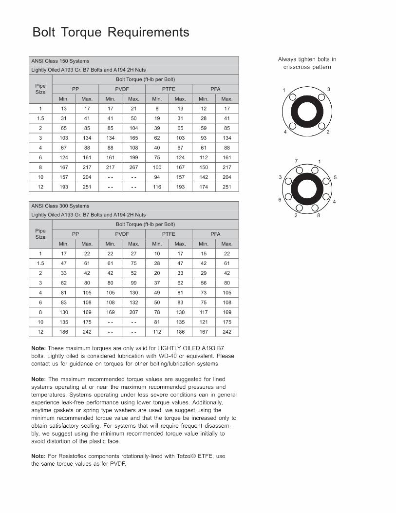
93
ANSI Class 150 Systems
Lightly Oiled A193 Gr. B7 Bolts and A194 2H Nuts
Pipe Size
Bolt Torque (ft-lb per Bolt)
PP PVDF PTFE PFA
Min. Max. Min. Max. Min. Max. Min. Max.
1 13 17 17 21 8 13 12 17
1.5 31 41 41 50 19 31 28 41
2 65 85 85 104 39 65 59 85
3 103 134 134 165 62 103 93 134
4 67 88 88 108 40 67 61 88
6 124 161 161 199 75 124 112 161
8 167 217 217 267 100 167 150 217
10 157 204 - - - - 94 157 142 204
12 193 251 - - - - 116 193 174 251
ANSI Class 300 Systems
Lightly Oiled A193 Gr. B7 Bolts and A194 2H Nuts
Pipe Size
Bolt Torque (ft-lb per Bolt)
PP PVDF PTFE PFA
Min. Max. Min. Max. Min. Max. Min. Max.
1 17 22 22 27 10 17 15 22
1.5 47 61 61 75 28 47 42 61
2 33 42 42 52 20 33 29 42
3 62 80 80 99 37 62 56 80
4 81 105 105 130 49 81 73 105
6 83 108 108 132 50 83 75 108
8 130 169 169 207 78 130 117 169
10 135 175 - - - - 81 135 121 175
12 186 242 - - - - 112 186 167 242
Bolt Torque Requirements
1 3
4 2
7 1
3 5
6 4
2 8
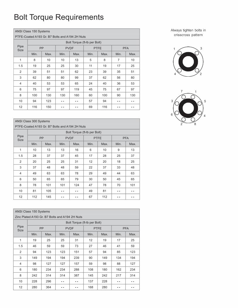
94
ANSI Class 150 Systems
PTFE-Coated A193 Gr. B7 Bolts and A194 2H Nuts
Pipe Size
Bolt Torque (ft-lb per Bolt)
PP PVDF PTFE PFA
Min. Max. Min. Max. Min. Max. Min. Max.
1 8 10 10 13 5 8 7 10
1.5 19 25 25 30 11 19 17 25
2 39 51 51 62 23 39 35 51
3 62 80 80 99 37 62 56 80
4 40 53 53 65 24 40 36 53
6 75 97 97 119 45 75 67 97
8 100 130 130 160 60 100 90 130
10 94 123 - - - - 57 94 - - - -
12 116 150 - - - - 69 116 - - - -
ANSI Class 300 Systems
PTFE-Coated A193 Gr. B7 Bolts and A194 2H Nuts
Pipe Size
Bolt Torque (ft-lb per Bolt)
PP PVDF PTFE PFA
Min. Max. Min. Max. Min. Max. Min. Max.
1 10 13 13 16 6 10 9 13
1.5 28 37 37 45 17 28 25 37
2 20 25 25 31 12 20 18 25
3 37 48 48 59 22 37 33 48
4 49 63 63 78 29 49 44 63
6 50 65 65 79 30 50 45 65
8 78 101 101 124 47 78 70 101
10 81 105 - - - - 49 81 - - - -
12 112 145 - - - - 67 112 - - - -
Bolt Torque Requirements
1 3
4 2
7 1
3 5
6 4
2 8
ANSI Class 150 Systems
Zinc Plated A193 Gr. B7 Bolts and A194 2H Nuts
Pipe Size
Bolt Torque (ft-lb per Bolt)
PP PVDF PTFE PFA
Min. Max. Min. Max. Min. Max. Min. Max.
1 19 25 25 31 12 19 17 25
1.5 46 59 59 73 27 46 41 59
2 94 123 123 151 57 94 85 123
3 149 194 194 239 90 149 134 194
4 98 127 127 157 59 98 88 127
6 180 234 234 288 108 180 162 234
8 242 314 314 387 145 242 217 314
10 228 296 - - - - 137 228 - - - -
12 280 364 - - - - 168 280 - - - -
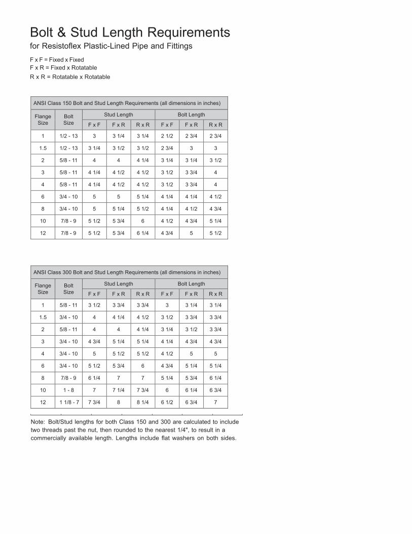
95
Bolt & Stud Length Requirements for Resistoflex Plastic-Lined Pipe and Fittings
F x F = Fixed x Fixed F x R = Fixed x Rotatable R x R = Rotatable x Rotatable
ANSI Class 150 Bolt and Stud Length Requirements (all dimensions in inches)
Flange Size
Bolt Size
Stud Length Bolt Length
F x F F x R R x R F x F F x R R x R
1 1/2 - 13 3 3 1/4 3 1/4 2 1/2 2 3/4 2 3/4
1.5 1/2 - 13 3 1/4 3 1/2 3 1/2 2 3/4 3 3
2 5/8 - 11 4 4 4 1/4 3 1/4 3 1/4 3 1/2
3 5/8 - 11 4 1/4 4 1/2 4 1/2 3 1/2 3 3/4 4
4 5/8 - 11 4 1/4 4 1/2 4 1/2 3 1/2 3 3/4 4
6 3/4 - 10 5 5 5 1/4 4 1/4 4 1/4 4 1/2
8 3/4 - 10 5 5 1/4 5 1/2 4 1/4 4 1/2 4 3/4
10 7/8 - 9 5 1/2 5 3/4 6 4 1/2 4 3/4 5 1/4
12 7/8 - 9 5 1/2 5 3/4 6 1/4 4 3/4 5 5 1/2
ANSI Class 300 Bolt and Stud Length Requirements (all dimensions in inches)
Flange Size
Bolt Size
Stud Length Bolt Length
F x F F x R R x R F x F F x R R x R
1 5/8 - 11 3 1/2 3 3/4 3 3/4 3 3 1/4 3 1/4
1.5 3/4 - 10 4 4 1/4 4 1/2 3 1/2 3 3/4 3 3/4
2 5/8 - 11 4 4 4 1/4 3 1/4 3 1/2 3 3/4
3 3/4 - 10 4 3/4 5 1/4 5 1/4 4 1/4 4 3/4 4 3/4
4 3/4 - 10 5 5 1/2 5 1/2 4 1/2 5 5
6 3/4 - 10 5 1/2 5 3/4 6 4 3/4 5 1/4 5 1/4
8 7/8 - 9 6 1/4 7 7 5 1/4 5 3/4 6 1/4
10 1 - 8 7 7 1/4 7 3/4 6 6 1/4 6 3/4
12 1 1/8 - 7 7 3/4 8 8 1/4 6 1/2 6 3/4 7
Note: Bolt/Stud lengths for both Class 150 and 300 are calculated to include two threads past the nut, then rounded to the nearest 1/4", to result in a commercially available length. Lengths include flat washers on both sides.
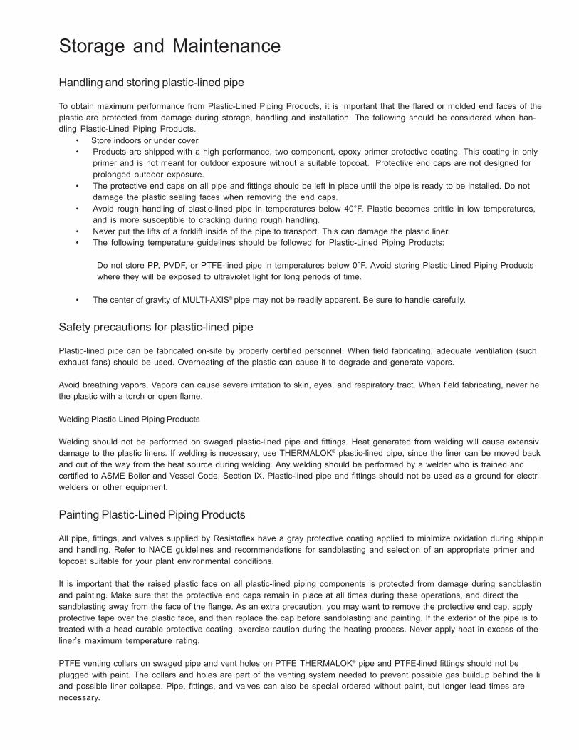
96
Storage and Maintenance
Handling and storing plastic-lined pipe
To obtain maximum performance from Plastic-Lined Piping Products, it is important that the flared or molded end faces of the plastic are protected from damage during storage, handling and installation. The following should be considered when han- dling Plastic-Lined Piping Products.
• Store indoors or under cover. • Products are shipped with a high performance, two component, epoxy primer protective coating. This coating in only
primer and is not meant for outdoor exposure without a suitable topcoat. Protective end caps are not designed for prolonged outdoor exposure.
• The protective end caps on all pipe and fittings should be left in place until the pipe is ready to be installed. Do not damage the plastic sealing faces when removing the end caps.
• Avoid rough handling of plastic-lined pipe in temperatures below 40°F. Plastic becomes brittle in low temperatures, and is more susceptible to cracking during rough handling.
• Never put the lifts of a forklift inside of the pipe to transport. This can damage the plastic liner. • The following temperature guidelines should be followed for Plastic-Lined Piping Products:
Do not store PP, PVDF, or PTFE-lined pipe in temperatures below 0°F. Avoid storing Plastic-Lined Piping Products where they will be exposed to ultraviolet light for long periods of time.
• The center of gravity of MULTI-AXIS® pipe may not be readily apparent. Be sure to handle carefully.
Safety precautions for plastic-lined pipe
Plastic-lined pipe can be fabricated on-site by properly certified personnel. When field fabricating, adequate ventilation (such exhaust fans) should be used. Overheating of the plastic can cause it to degrade and generate vapors.
Avoid breathing vapors. Vapors can cause severe irritation to skin, eyes, and respiratory tract. When field fabricating, never he the plastic with a torch or open flame.
Welding Plastic-Lined Piping Products
Welding should not be performed on swaged plastic-lined pipe and fittings. Heat generated from welding will cause extensiv damage to the plastic liners. If welding is necessary, use THERMALOK® plastic-lined pipe, since the liner can be moved back and out of the way from the heat source during welding. Any welding should be performed by a welder who is trained and certified to ASME Boiler and Vessel Code, Section IX. Plastic-lined pipe and fittings should not be used as a ground for electri welders or other equipment.
Painting Plastic-Lined Piping Products
All pipe, fittings, and valves supplied by Resistoflex have a gray protective coating applied to minimize oxidation during shippin and handling. Refer to NACE guidelines and recommendations for sandblasting and selection of an appropriate primer and topcoat suitable for your plant environmental conditions.
It is important that the raised plastic face on all plastic-lined piping components is protected from damage during sandblastin and painting. Make sure that the protective end caps remain in place at all times during these operations, and direct the sandblasting away from the face of the flange. As an extra precaution, you may want to remove the protective end cap, apply protective tape over the plastic face, and then replace the cap before sandblasting and painting. If the exterior of the pipe is to treated with a head curable protective coating, exercise caution during the heating process. Never apply heat in excess of the liner’s maximum temperature rating.
PTFE venting collars on swaged pipe and vent holes on PTFE THERMALOK® pipe and PTFE-lined fittings should not be plugged with paint. The collars and holes are part of the venting system needed to prevent possible gas buildup behind the li and possible liner collapse. Pipe, fittings, and valves can also be special ordered without paint, but longer lead times are necessary.
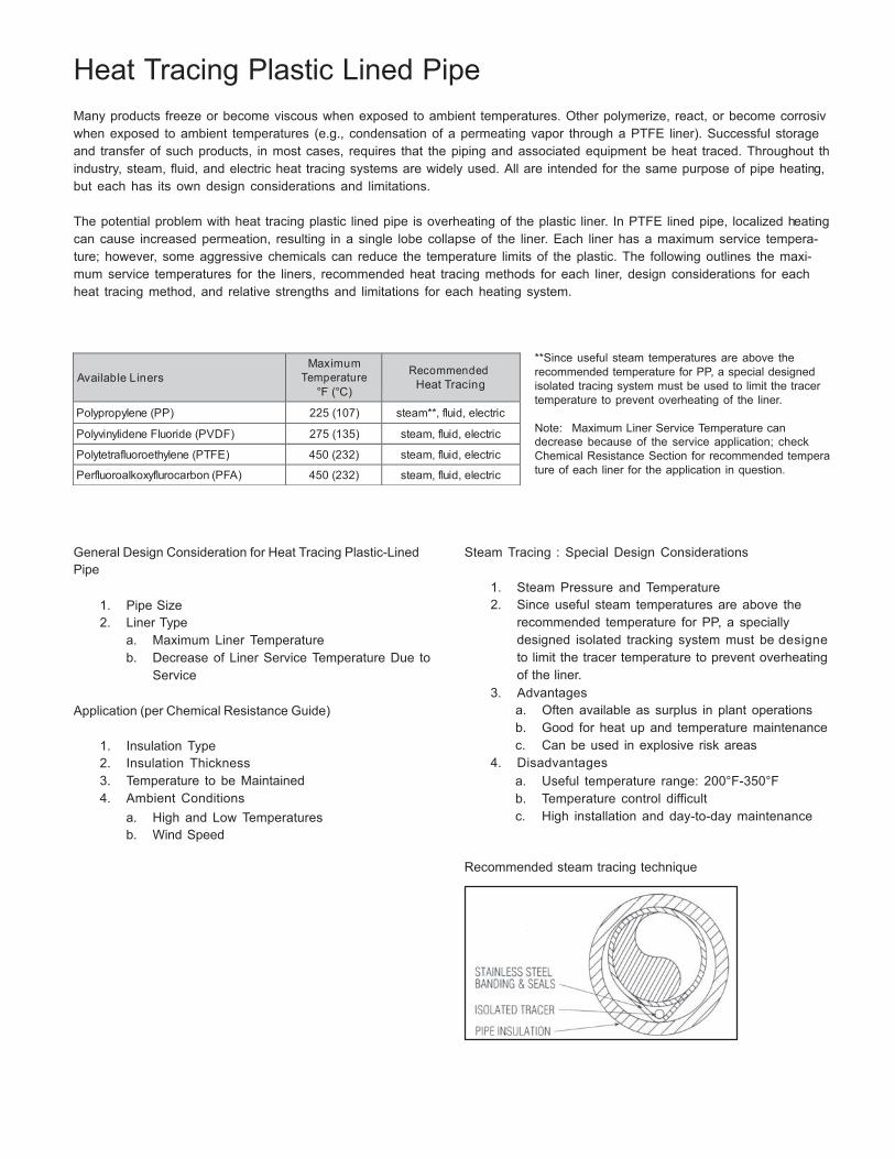
97
Available Liners
Maximum Temperature
°F (°C)
Recommended
Heat Tracing
Polypropylene (PP) 225 (107) steam**, fluid, electric
Polyvinylidene Fluoride (PVDF) 275 (135) steam, fluid, electric
Polytetrafluoroethylene (PTFE) 450 (232) steam, fluid, electric
Perfluoroalkoxyflurocarbon (PFA) 450 (232) steam, fluid, electric
Heat Tracing Plastic Lined Pipe
Many products freeze or become viscous when exposed to ambient temperatures. Other polymerize, react, or become corrosiv when exposed to ambient temperatures (e.g., condensation of a permeating vapor through a PTFE liner). Successful storage and transfer of such products, in most cases, requires that the piping and associated equipment be heat traced. Throughout th industry, steam, fluid, and electric heat tracing systems are widely used. All are intended for the same purpose of pipe heating, but each has its own design considerations and limitations.
The potential problem with heat tracing plastic lined pipe is overheating of the plastic liner. In PTFE lined pipe, localized heating can cause increased permeation, resulting in a single lobe collapse of the liner. Each liner has a maximum service tempera- ture; however, some aggressive chemicals can reduce the temperature limits of the plastic. The following outlines the maxi- mum service temperatures for the liners, recommended heat tracing methods for each liner, design considerations for each heat tracing method, and relative strengths and limitations for each heating system.
**Since useful steam temperatures are above the recommended temperature for PP, a special designed isolated tracing system must be used to limit the tracer temperature to prevent overheating of the liner.
Note: Maximum Liner Service Temperature can decrease because of the service application; check Chemical Resistance Section for recommended tempera ture of each liner for the application in question.
General Design Consideration for Heat Tracing Plastic-Lined Pipe
1. Pipe Size 2. Liner Type
a. Maximum Liner Temperature b. Decrease of Liner Service Temperature Due to
Service
Application (per Chemical Resistance Guide)
1. Insulation Type 2. Insulation Thickness 3. Temperature to be Maintained 4. Ambient Conditions
a. High and Low Temperatures b. Wind Speed
Steam Tracing : Special Design Considerations
1. Steam Pressure and Temperature 2. Since useful steam temperatures are above the
recommended temperature for PP, a specially designed isolated tracking system must be designe to limit the tracer temperature to prevent overheating of the liner.
3. Advantages a. Often available as surplus in plant operations b. Good for heat up and temperature maintenance c. Can be used in explosive risk areas
4. Disadvantages a. Useful temperature range: 200°F-350°F b. Temperature control difficult c. High installation and day-to-day maintenance
Recommended steam tracing technique
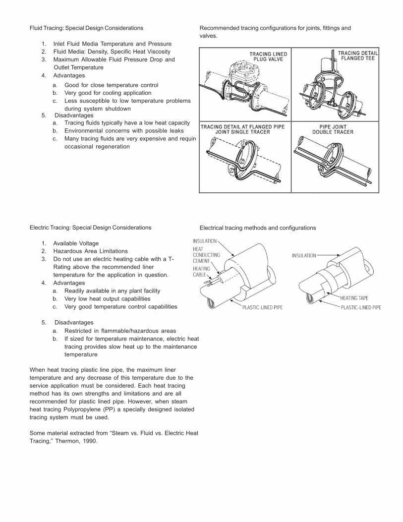
98
re
Fluid Tracing: Special Design Considerations
1. Inlet Fluid Media Temperature and Pressure 2. Fluid Media: Density, Specific Heat Viscosity 3. Maximum Allowable Fluid Pressure Drop and
Outlet Temperature 4. Advantages
a. Good for close temperature control b. Very good for cooling application c. Less susceptible to low temperature problems
during system shutdown 5. Disadvantages
a. Tracing fluids typically have a low heat capacity b. Environmental concerns with possible leaks c. Many tracing fluids are very expensive and requi
occasional regeneration
Electric Tracing: Special Design Considerations
1. Available Voltage 2. Hazardous Area Limitations 3. Do not use an electric heating cable with a T-
Rating above the recommended liner temperature for the application in question.
4. Advantages a. Readily available in any plant facility b. Very low heat output capabilities c. Very good temperature control capabilities
Recommended tracing configurations for joints, fittings and valves.
Electrical tracing methods and configurations
5. Disadvantages
a. Restricted in flammable/hazardous areas b. If sized for temperature maintenance, electric heat
tracing provides slow heat up to the maintenance temperature
When heat tracing plastic line pipe, the maximum liner temperature and any decrease of this temperature due to the service application must be considered. Each heat tracing method has its own strengths and limitations and are all recommended for plastic lined pipe. However, when steam heat tracing Polypropylene (PP) a specially designed isolated tracing system must be used.
Some material extracted from “Steam vs. Fluid vs. Electric Heat Tracing,” Thermon, 1990.
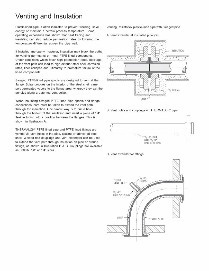
99
Venting and Insulation
Plastic-lined pipe is often insulated to prevent freezing, save energy or maintain a certain process temperature. Some operating experience has shown that heat tracing and insulating can also reduce permeation rates by lowering the temperature differential across the pipe wall.
If installed improperly, however, insulation may block the paths for venting permeants on most PTFE-lined components. Under conditions which favor high permeation rates, blockage of the vent path can lead to high exterior steel shell corrosion rates, liner collapse and ultimately to premature failure of the lined components.
Swaged PTFE-lined pipe spools are designed to vent at the flange. Spiral grooves on the interior of the steel shell trans- port permeated vapors to the flange area, whereby they exit the annulus along a patented vent collar.
When insulating swaged PTFE-lined pipe spools and flange connections, care must be taken to extend the vent path through the insulation. One simple way is to drill a hole through the bottom of the insulation and insert a piece of 1/4" flexible tubing into a position between the flanges. This is shown in Illustration A.
THERMALOK® PTFE-lined pipe and PTFE-lined fittings are vented via vent holes in the pipe, casting or fabricated steel shell. Welded half couplings and vent extenders can be used to extend the vent path through insulation on pipe or around fittings, as shown in Illustration B & C. Couplings are available as 3000lb. 1/8” or 1/4” sizes.
Venting Resistoflex plastic-lined pipe with Swaged pipe
A. Vent extender at insulated pipe joint
B. Vent holes and couplings on THERMALOK® pipe
C. Vent extender for fittings

DcZ FjVa^in LVn BVg^dc! C8 '-,*'
IZa/ (-'-) ,')")%%% ;Vm/ (-'-) ,')"),-(
lll#XgVcZX]Zbe]VgbV#Xdb
brands you trust.
CRANE Chempharma Flow Solutions Include: Pipe - Valves - Fittings - Actuators - Pumps
© 2009 CRANE ChemPharma Flow Solutions, www.cranechempharma.com
CP-RESISTOFLEX-00-CT-EN-MA-10/09