Embed Size (px)
Citation preview
Libra-1+V3.0 Product Handbook Wasion Group limited
Libra-1+ Single-phase Watt hour Meter
HANDBOOK
Wasion Technology (Shenzhen) Co., Ltd.
Prepared by: 2009-11-30 Document No.:OKRW2.702.513SS
Audit:Process: No. 1/Total: 34
Standardization:
Approval:
Libra-1+V3.0 Product Handbook Wasion Group limited
The information contained in this document is subject to change without
notice.Wasion makes no warranty of any kind with regard to this material, including,
but not limited to, the implied warranties of merchantability and fitness for a
particular purpose. Wasion will not be liable for errors contained herein or
incidental consequential damages in connection with the furnishing,
performance, or use of this material.This document contains proprietary information that is protected by copyright.
All rights are reserved. No part of this document may be photocopied or
otherwise reproduced without consent of Wasion
Document Edition index date Remarks1 2009-11-30 First edition2 2009-12-20 Adjust format
Copyright© 2007 by WasionPublished in a limited copyright sense, and all rights, including trade secrets
are reserved.
Prepared by: 2009-11-30 Document No.:OKRW2.702.513SS
Audit:Process: No. 2/Total: 34
Standardization:
Approval:
Libra-1+V3.0 Product Handbook Wasion Group limited
Table of Contents
1.0 Product Description...............................................................................................5
1.1 General Information...........................................................................................................5
1.1.1 ANSI Standard Compatible................................................................................71.1.2 Product List.......................................................................................................81.1.3 Physical Description..........................................................................................81.1.4 Meter Forms...................................................................................................101.1.5 Basic Data Sheet..............................................................................................10
1.2 Normal Operating Mode...................................................................................................11
1.3 Software Tool....................................................................................................................12
1.4 Technical Information.......................................................................................................12
1.4.1 Theory of Operation...............................................................................................12
2 Operating Instructions............................................................................................15
2.1 Mechanical Structure........................................................................................................15
2.1.1 Cover......................................................................................................................152.1.2 AMR module, Relay(Optional)...............................................................................17
2.2 Nameplate Information and Labels..................................................................................17
2.2.1 Nameplate Information.........................................................................................172.3 Display...............................................................................................................................18
2.3.1 Display elements....................................................................................................182.3.2 Energy Accumulation.............................................................................................19
3.0 Maintenance Instructions....................................................................................20
3.1 Test Procedures................................................................................................................20
3.1.1 Meter Testing Tools...............................................................................................203.2 Field Accuracy Test...........................................................................................................21
3.3 Shop Test..........................................................................................................................21
Prepared by: 2009-11-30 Document No.:OKRW2.702.513SS
Audit:Process: No. 3/Total: 34
Standardization:
Approval:
Libra-1+V3.0 Product Handbook Wasion Group limited
3.3.1 Meter Shop Equipment..........................................................................................213.3.1.1 Equipment Setup................................................................................................223.3.1.2 Testing.................................................................................................................223.3.2 General Watt-hour Meter Test Procedure.............................................................22
3.4 Service...............................................................................................................................23
3.5 Repair................................................................................................................................23
3.6 Returning a Meter.............................................................................................................23
3.7 Cleaning............................................................................................................................24
3.8 Storage..............................................................................................................................24
3.9 Troubleshooting Guide.....................................................................................................24
3.9.1 Self-Tests and Error Codes.....................................................................................25
4.0 Installation Instructions.......................................................................................25
4.1 General.............................................................................................................................25
4.2 Inspection.........................................................................................................................25
4.3 Storage..............................................................................................................................26
4.4 Unpacking.........................................................................................................................26
4.5 Selecting a site..................................................................................................................26
4.6 Meter installation.............................................................................................................26
5.0 Site Analysis Guides and Diagram.....................................................................27
5.1 Form 1S (Self-Contained)..................................................................................................28
5.2 Form 2S (Self-Contained)..................................................................................................28
5.3 Form 3S (Transformer Rated)...........................................................................................29
5.4 Form 3S (Transformer Rated)...........................................................................................29
5.5 Form 4S (Transformer Rated)...........................................................................................30
5.6 Diagrams...........................................................................................................................31
6.0 Appendix................................................................................................................32
Prepared by: 2009-11-30 Document No.:OKRW2.702.513SS
Audit:Process: No. 4/Total: 34
Standardization:
Approval:
Libra-1+V3.0 Product Handbook Wasion Group limited
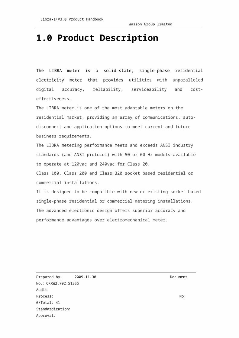
1.0 Product Description
The LIBRA meter is a solid-state, single-phase residential electricity meter that
provides utilities with unparalleled digital accuracy, reliability, serviceability
and cost-effectiveness.The LIBRA meter is one of the most adaptable meters on the residential
market, providing an array of communications, auto-disconnect and
application options to meet current and future business requirements.The LIBRA metering performance meets and exceeds ANSI industry standards
(and ANSI protocol) with 50 or 60 Hz models available to operate at 120vac
and 240vac for Class 20,Class 100, Class 200 and Class 320 socket based residential or commercial
installations.It is designed to be compatible with new or existing socket based single-phase
residential or commercial metering installations. The advanced electronic
design offers superior accuracy and performance advantages over
electromechanical meter.
Prepared by: 2009-11-30 Document No.:OKRW2.702.513SS
Audit:Process: No. 5/Total: 34
Standardization:
Approval:
Libra-1+V3.0 Product Handbook Wasion Group limited
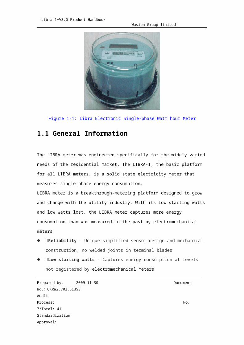
Figure 1-1: Libra Electronic Single-phase Watt hour Meter
1.1 General Information
The LIBRA meter was engineered specifically for the widely varied needs of
the residential market. The LIBRA-I, the basic platform for all LIBRA meters, is
a solid state electricity meter that measures single-phase energy
consumption. LIBRA meter is a breakthrough-metering platform designed to grow and
change with the utility industry. With its low starting watts and low watts lost,
the LIBRA meter captures more energy consumption than was measured in
the past by electromechanical meters Reliability - Unique simplified sensor design and mechanical
construction; no welded joints in terminal blades Low starting watts - Captures energy consumption at levels not
registered by electromechanical meters Low burden - Minimizes utility system losses Tamper-resistant design - Minimizes theft of service. Programmable to
register energy when meter inverted (turning the meter upside down)
Prepared by: 2009-11-30 Document No.:OKRW2.702.513SS
Audit:Process: No. 6/Total: 34
Standardization:
Approval:
Libra-1+V3.0 Product Handbook Wasion Group limited
Friendly display –Large LCD, two line display, more easy to read Nocturnal visibility - When the environment low light, the LCD backlight
automatically open. Remote Disconnect (optional, 200A max) - In many markets, and in
future expected markets, it is necessary to be able to interrupt the flow of
power through the meter, disconnecting the home or business from the
grid. Additionally, the Libra meter can be programmed to automatically
disconnect power. The disconnect switch is fully integrated inside the
Libra-1+. This is a factory-installed option that must be specified at the
time of order. To take advantage of all of the functionality this option
offers, a two-way AMR device and system should be employed. Network Applications - The Libra is available in 12S and 25S forms for
network applications. Four options for Energy Accumulation - Delivered only, Delivered +
Received,Delivered – Received, Received only); one option must be specified at
time of order, but changes can be made after the fact via Wasion
MeterBuddy® Software.Boosts operational efficiency - Factory programming minimizes handling Inventory management - Compatible with existing LIBRA-I+® cover
stock .the meter measures kWh/kVarh energy and is rated as an ANSI
C12.10 class 0.5 meter. However, it is expected that accuracy under
many operating conditions and loads will typically be within 0.2%. The
meter is configured at the factory. Resetting energy is accomplished with
MeterBuddy® software (Version 1.0 or greater) and some keys which
used to operate meter. The Liquid Crystal Display (LCD) indicates energy
consumption,current rate,used days,meter state.The display is covered in
Prepared by: 2009-11-30 Document No.:OKRW2.702.513SS
Audit:Process: No. 7/Total: 34
Standardization:
Approval:
Libra-1+V3.0 Product Handbook Wasion Group limited
detail in Chapter 2, Operation Instructions. The 6 large characters of the
LCD display alphanumeric information. A configuration port is located at
the 7 o’clock position of the meter face. The factory uses the
configuration port to configure the meter for a specific application. It is
also used in conjunction with a reset adaptor and MeterBuddy® software
to reset accumulated energy to zero
1.1.1 ANSI Standard Compatible
Meets applicable standards: ANSI C12.1-1995 ANSI C12.10-1997 ANSI C12.18-1996 ANSI C12.19-1997 ANSI C12.20(Class 0.5)-1998 ANSI C37.90.1-1989 ANSI C62.45-1992 IEC 61000-4-4 IEC61000-4-2 FCC Part 15,Subclass C DL/T645-2007 DL/T698-1999
1.1.2 Product List
The LIBRA meter is available with a series of options, offering the ideal
Prepared by: 2009-11-30 Document No.:OKRW2.702.513SS
Audit:Process: No. 8/Total: 34
Standardization:
Approval:
Libra-1+V3.0 Product Handbook Wasion Group limited
solution for a range of different residential needs. All kind of product list show
as the following tables
TYPE Class Volts Wire Form AMR Port Disconnect
Libra-1a 100 120/240 2 1S No NoLibra-1+
Libra-1+V3.0Libra-1bLibra-1c
200 240 3 2S Optional Optional
Libra-1bLibra-1c
320 240 3 2S Optional No
Libra-1a 20 120/240 2 3S No NoLibra-1bLibra-1c
20 120/240 3 4S Optional Optional
Libra-1c 200 120 3 12S Optional OptionalLibra-1c 200 120 3 25S Optional Optional
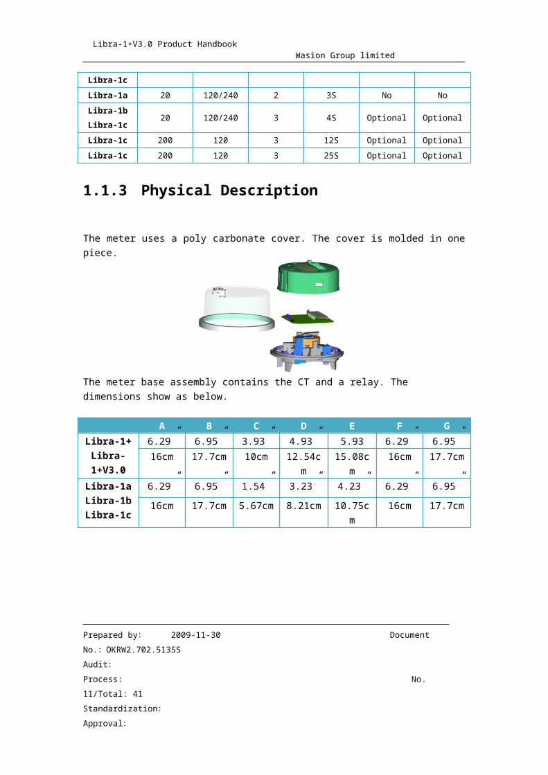
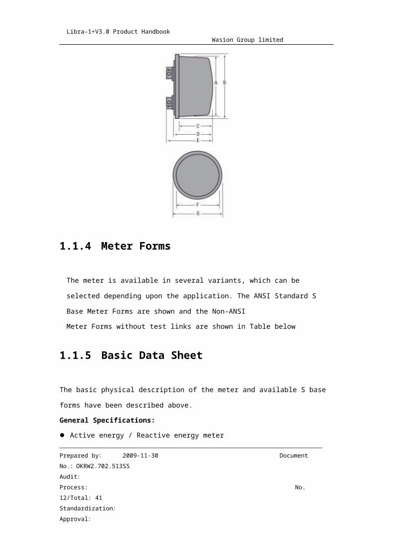
1.1.3 Physical Description
The meter uses a poly carbonate cover. The cover is molded in one piece.
The meter base assembly contains the CT and a relay. The dimensions show as below.
A B C D E F GLibra-1+ 6.29” 6.95” 3.93” 4.93” 5.93 6.29” 6.95”
Prepared by: 2009-11-30 Document No.:OKRW2.702.513SS
Audit:Process: No. 9/Total: 34
Standardization:
Approval:

Libra-1+V3.0 Product Handbook Wasion Group limited
Libra-1+V3.0 16cm 17.7cm 10cm 12.54cm 15.08cm 16cm 17.7cmLibra-1aLibra-1bLibra-1c
6.29” 6.95” 1.54” 3.23” 4.23” 6.29” 6.95”
16cm 17.7cm 5.67cm 8.21cm 10.75cm 16cm 17.7cm
1.1.4 Meter Forms
The meter is available in several variants, which can be selected depending upon the
application. The ANSI Standard S Base Meter Forms are shown and the Non-ANSI
Meter Forms without test links are shown in Table below
1.1.5 Basic Data Sheet
The basic physical description of the meter and available S base forms have been
described above.
Prepared by: 2009-11-30 Document No.:OKRW2.702.513SS
Audit:Process: No. 10/Total: 34
Standardization:
Approval:
Libra-1+V3.0 Product Handbook Wasion Group limited
General Specifications:
Active energy / Reactive energy meter
Received kWh / Delivered kWh / Delivered kWh + Received kWh / Delivered kWh -
Received kWh meter
Digital Multiplication Measurement Technique
Non-Volatile Memory
Designed for 15+ years life
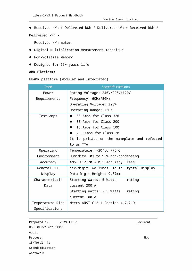
AMR Platform:
AMR platform (Modular and Integrated)
Item Specifications Power Requirements Rating Voltage: 240V/220V/120V Frequency:
60Hz/50HzOperating Voltage: ±20%Operating Range: ±3Hz
Test Amps 50 Amps for Class 320 30 Amps for Class 200 15 Amps for Class 100 2.5 Amps for Class 20It is printed on the nameplate and referred to as “TA”
Operating Environment
Temperature: -20°to +75℃Humidity: 0% to 95% non-condensing
Accuracy ANSI C12.20 - 0.5 Accuracy ClassGeneral LCD Display six-digit Two lines Liquid Crystal Display
Data Digit Height: 9.67mmCharacteristic Data Starting Watts: 5 Watts rating current:200 A
Starting Watts: 2.5 Watts rating current:100 ATemperature Rise
SpecificationsMeets ANSI C12.1 Section 4.7.2.9
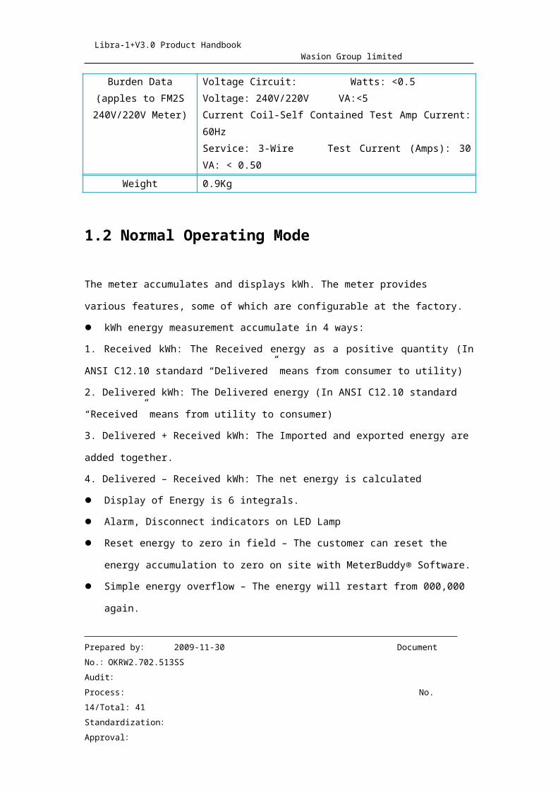
Burden Data(apples to FM2S
240V/220V Meter)
Voltage Circuit: Watts: <0.5Voltage: 240V/220V VA:<5Current Coil-Self Contained Test Amp Current: 60HzService: 3-Wire Test Current (Amps): 30 VA: < 0.50
Prepared by: 2009-11-30 Document No.:OKRW2.702.513SS
Audit:Process: No. 11/Total: 34
Standardization:
Approval:
Libra-1+V3.0 Product Handbook Wasion Group limited
Weight 0.9Kg
1.2 Normal Operating Mode
The meter accumulates and displays kWh. The meter provides various
features, some of which are configurable at the factory. kWh energy measurement accumulate in 4 ways: 1. Received kWh: The Received energy as a positive quantity (In ANSI C12.10
standard “Delivered” means from consumer to utility)2. Delivered kWh: The Delivered energy (In ANSI C12.10 standard “Received”
means from utility to consumer)3. Delivered + Received kWh: The Imported and exported energy are added
together.4. Delivered – Received kWh: The net energy is calculated Display of Energy is 6 integrals. Alarm, Disconnect indicators on LED Lamp Reset energy to zero in field – The customer can reset the energy
accumulation to zero on site with MeterBuddy® Software. Simple energy overflow – The energy will restart from 000,000 again. IR, which used to communicate with the MeterBuddy® software. PLC(Power line Communication), which used to communicate with the
server.
1.3 Software Tool
The meter is supported by the MeterBuddy® Software (version 1.0 or greater), which
facilitates the resetting of the energy accumulation to zero, calibrate and other functions.
Prepared by: 2009-11-30 Document No.:OKRW2.702.513SS
Audit:Process: No. 12/Total: 34
Standardization:
Approval:
Libra-1+V3.0 Product Handbook Wasion Group limited
Refer to Reading and Programming Instruction manual for MeterBuddy®.
There is a reset adaptor that is available, part number WH109-1. The adaptor fits over a
optical port to connect to PC’s RS232 port.
1.4 Technical Information
1.4.1 Theory of Operation
The theory of operation of Single Phase meter is explained in conjunction with the
block diagram shown in Figure 1-3.
Prepared by: 2009-11-30 Document No.:OKRW2.702.513SS
Audit:Process: No. 13/Total: 34
Standardization:
Approval:
Libra-1+V3.0 Product Handbook Wasion Group limited
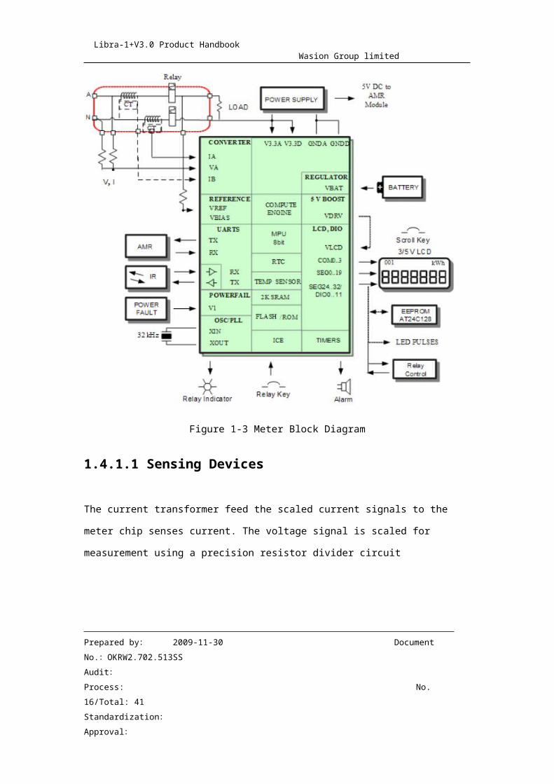
Figure 1-3 Meter Block Diagram
1.4.1.1 Sensing Devices
The current transformer feed the scaled current signals to the meter chip senses current.
The voltage signal is scaled for measurement using a precision resistor divider circuit
1.4.1.2 Meter Chip
Single Converter Technologywith a 21-bit delta-sigma ADC
4 analog inputs plus auxiliary inputs
Prepared by: 2009-11-30 Document No.:OKRW2.702.513SS
Audit:Process: No. 14/Total: 34
Standardization:
Approval:
Libra-1+V3.0 Product Handbook Wasion Group limited
On-chip temperature measurement for digital temperature compensation
Precision voltage reference
32-bit compute engine
8051-based MPU (80515), 1 clock cycle per instruction
Real Time Clock (RTC)
152 segments for LCD drive
UARTs.
Voltage comparator(s)
Hardware Watch Dog Timer.
Synchronous serial interface (SSI) for real time data.
Real-time monitoring of CE variables
1.4.1.3 EEPROM
The ANSI C12.10 meter is equipped with a non-volatile memory that is used to store
the metered data, calibration parameters, configuration constants and the program
parameters. The non-volatile memory does not require a battery to retain information
when line power is not present.
Schmitt Trigger, Filtered Inputs for Noise Suppression
Write Protect Pin for Hardware and Software Data Protection
High Reliability
Data Retention: 40 Years
1.4.1.4 Relay
The Libra-1+V3.0 meter is equipped with a 200A(max) relay that is used to remote-
disconnect the power supply
Prepared by: 2009-11-30 Document No.:OKRW2.702.513SS
Audit:Process: No. 15/Total: 34
Standardization:
Approval:
Libra-1+V3.0 Product Handbook Wasion Group limited
1.4.1.5 LCD
LCD is designed to meet customer needs e.g. The balance of electricity, Cumulative total
electricity consumption ,Multi-Rate electricity consumption,But the ANSI C12.10 meter
only implement basic function.
1.4.1.6 Infrared optical port
The optical port meets to C12.18-1996 physical layer standard. This port is used to
communication with computer tools. The computer tools can be used to program meter.
1.4.1.7 AMR Uart Port
The AMR port is a UART, which meets to DL/T645-2007 standard. This port can be used
to communication with inner AMR module, such as RF/PLC/Zigbee etc.
1.4.1.8 Pulses output LED
The Libra meter is equipped a IR that is used to kWh pulse output.
Prepared by: 2009-11-30 Document No.:OKRW2.702.513SS
Audit:Process: No. 16/Total: 34
Standardization:
Approval:
Libra-1+V3.0 Product Handbook Wasion Group limited
2 Operating Instructions
2.1 Mechanical Structure
2.1.1 Cover
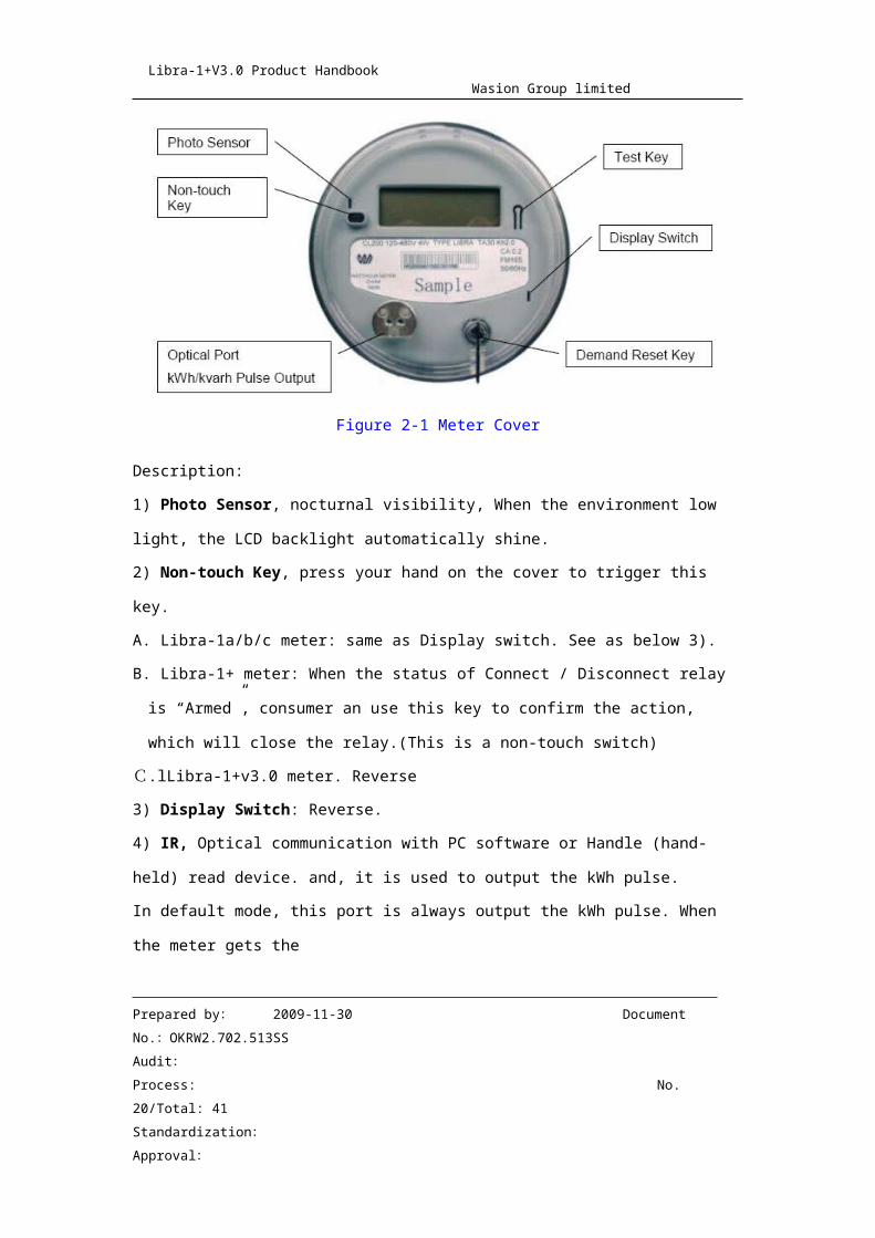
See Figure 2-1 for a graphic representation of the meter cover.
Figure 2-1 Meter Cover
Description:
1) Photo Sensor, nocturnal visibility, When the environment low light, the LCD backlight
automatically shine.
2) Non-touch Key, press your hand on the cover to trigger this key.
A. Libra-1a/b/c meter: same as Display switch. See as below 3).
B. Libra-1+ meter: When the status of Connect / Disconnect relay is “Armed”, consumer
an use this key to confirm the action, which will close the relay.(This is a non-touch
Prepared by: 2009-11-30 Document No.:OKRW2.702.513SS
Audit:Process: No. 17/Total: 34
Standardization:
Approval:
Libra-1+V3.0 Product Handbook Wasion Group limited
switch)
C.lLibra-1+v3.0 meter. Reverse
3) Display Switch: Reverse.
4) IR, Optical communication with PC software or Handle (hand-held) read device. and, it
is used to output the kWh pulse.
In default mode, this port is always output the kWh pulse. When the meter gets the
optical communication signal, it will switch to communication mode automatically.
5) Energy Reset Key, Used to clear energy.
6) Test Key, switch to Test Mode.
7) Alarm/Disconnect LED Indicator, LED On indicators relay disconnect, LED Blinking
indicators Relay connect and Balance is Alarming, LED off when Relay connect and
Balance isn’t Alarming.
2.1.2 AMR module, Relay(Optional)
Libra can equipped with all kinds of AMR modules, and the relay is from 60Amax to
200Amax.
2.2 Nameplate Information and Labels
2.2.1 Nameplate Information
See Figure 2-2 for a graphic representation of the meter nameplate. The meter
nameplate is found on the front of the meter.
Prepared by: 2009-11-30 Document No.:OKRW2.702.513SS
Audit:Process: No. 18/Total: 34
Standardization:
Approval:
Libra-1+V3.0 Product Handbook Wasion Group limited
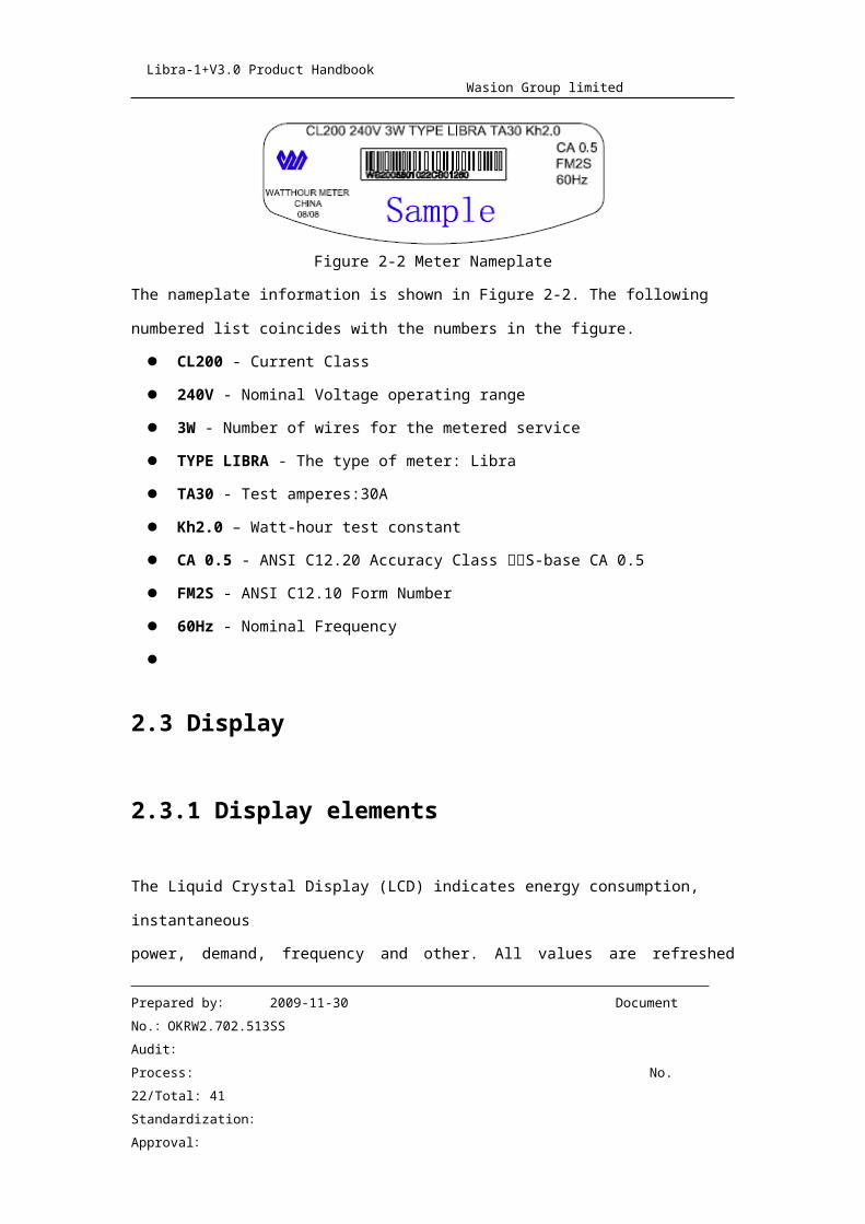
Figure 2-2 Meter Nameplate
The nameplate information is shown in Figure 2-2. The following numbered list coincides
with the numbers in the figure.
CL200 - Current Class
240V - Nominal Voltage operating range
3W - Number of wires for the metered service
TYPE LIBRA - The type of meter: Libra
TA30 - Test amperes:30A
Kh2.0 – Watt-hour test constant
CA 0.5 - ANSI C12.20 Accuracy Class S-base CA 0.5
FM2S - ANSI C12.10 Form Number
60Hz - Nominal Frequency
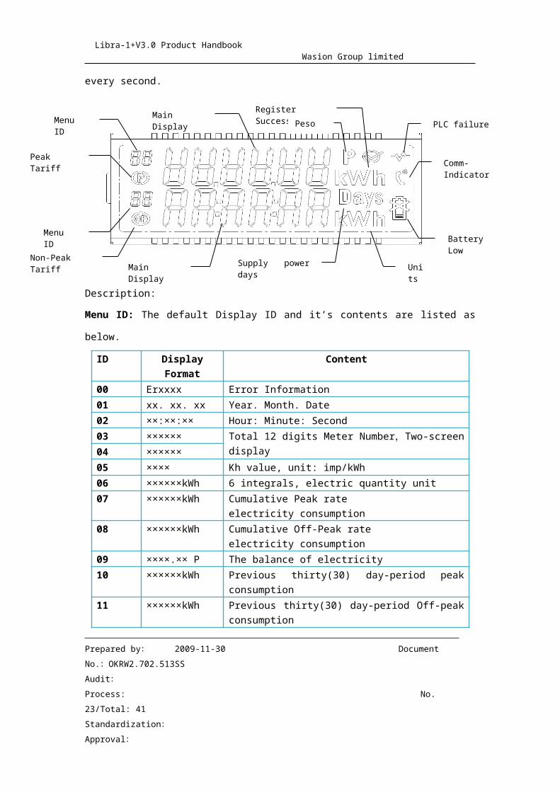
2.3 Display
2.3.1 Display elements
The Liquid Crystal Display (LCD) indicates energy consumption, instantaneous
power, demand, frequency and other. All values are refreshed every second.
Prepared by: 2009-11-30 Document No.:OKRW2.702.513SS
Audit:Process: No. 19/Total: 34
Standardization:
Approval:
Main Display
Non-Peak Tariff
Peak Tariff
Menu ID
Menu ID
Register Success
Peso PLC failure
Comm-Indicator
Battery Low
Units
Main Display Supply power days
Libra-1+V3.0 Product Handbook Wasion Group limited
Description:
Menu ID: The default Display ID and it’s contents are listed as below.
ID Display Format Content00 Erxxxx Error Information01 xx. xx. xx Year. Month. Date02 ××:××:×× Hour: Minute: Second03 ×××××× Total 12 digits Meter Number,Two-screen display04 ××××××05 ×××× Kh value, unit: imp/kWh 06 ××××××kWh 6 integrals, electric quantity unit07 ××××××kWh Cumulative Peak rate
electricity consumption08 ××××××kWh Cumulative Off-Peak rate
electricity consumption09 ××××.×× P The balance of electricity10 ××××××kWh Previous thirty(30) day-period peak consumption11 ××××××kWh Previous thirty(30) day-period Off-peak consumption12 ××××××kWh Current thirty(30) day-period peak consumption13 ××××××kWh Current thirty(30) day-period Off-peak consumption14 Xx Days Number of days into the current month-period
Prepared by: 2009-11-30 Document No.:OKRW2.702.513SS
Audit:Process: No. 20/Total: 34
Standardization:
Approval:
Libra-1+V3.0 Product Handbook Wasion Group limited
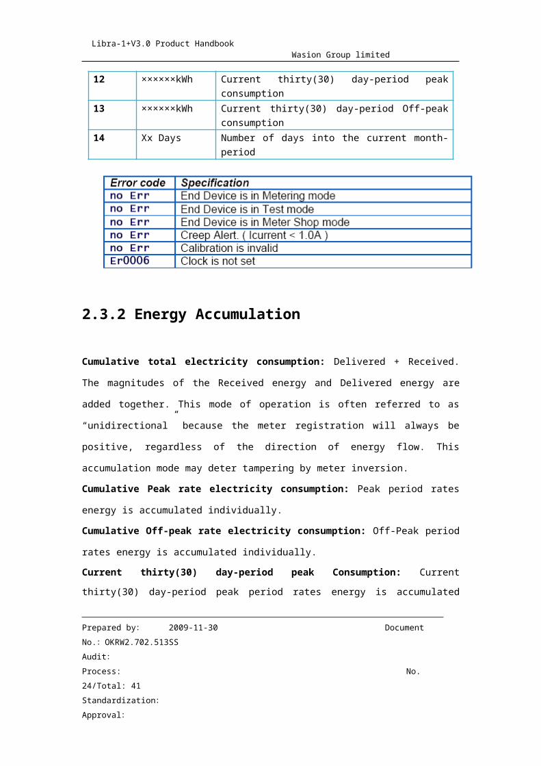
2.3.2 Energy Accumulation
Cumulative total electricity consumption: Delivered + Received. The magnitudes of
the Received energy and Delivered energy are added together. This mode of operation is
often referred to as “unidirectional” because the meter registration will always be positive,
regardless of the direction of energy flow. This accumulation mode may deter tampering
by meter inversion.
Cumulative Peak rate electricity consumption: Peak period rates energy is
accumulated individually.
Cumulative Off-peak rate electricity consumption: Off-Peak period rates energy is
accumulated individually.
Current thirty(30) day-period peak Consumption: Current thirty(30) day-period peak
period rates energy is accumulated individually.
Current thirty(30) day-period Off-peak consumption: Current thirty(30) day-period
Off-peak period rates energy is accumulated individually
Last month peak, off-peak tariff consumption: On setting dump days and billing time ,
meter dump the current peak/off-peak consumption to the last month peak/off-peak
register, and then reset the current peak/off-peak register .if power off at dump day,
meter only dump the once after power on, regardless of whether power off duration cross
dump days
Last thirty day consumption load profile: meter can record 30 day energy
consumption load profile(interval:1 day), .if power off at 24:00 daily, meter only save the
once after power on, regardless of power off duration
Prepared by: 2009-11-30 Document No.:OKRW2.702.513SS
Audit:Process: No. 21/Total: 34
Standardization:
Approval:
Libra-1+V3.0 Product Handbook Wasion Group limited
3.0 Maintenance Instructions
WARNING: The information contained within this document is intended to be an aid to
Qualified metering personnel. It is not intended to replace the extensive training
necessary to install or remove meters from service. Any work on or near energized
meters, meter sockets, or other metering equipment presents the danger or electrical
shock. All work on these products must be performed by qualified industrial electricians
and metering specialists only.
All work must be done in accordance with local utility safety practices and the procedures
outlined in the current edition of the Handbook for Electricity Metering.
3.1 Test Procedures
The Procedures described below are suggested test procedures for use with the Libra
meter. They are not intended to replace local utility operating practices.
3.1.1 Meter Testing Tools
The meter is equipped with a light-emitting diode (IR LED) for verifying calibration
3.1.1.1 Calibration LED
The Infra-Red LED emits optical pulses proportional to kWh accumulation. The output of
the calibration LED is compatible with commercially available test equipment designed
to verify the calibration of watt-hour meters in the shop and field. Each calibration pulse
represents Kh watt-hours of energy accumulated by the meter. The duration of each
Prepared by: 2009-11-30 Document No.:OKRW2.702.513SS
Audit:Process: No. 22/Total: 34
Standardization:
Approval:
Libra-1+V3.0 Product Handbook Wasion Group limited
output pulse is approximately 10 milliseconds
3.2 Field Accuracy Test
The most accurate way to verify meter calibration is the use of test equipment designed
to compare the meter accumulation to a precision watt-hour standard. This equipment
uses the calibration pulse output from the meter to gate (start and stop) the standard at
precise times to minimize the measurement uncertainty. The equipment will also
typically provide known regulated loads to the meter and standard during the test. In the
event such equipment is not available, the Libra meter provides two methods for making
a reasonable verification of the meter’s accuracy.
1. Disk analog testing
2. Instantaneous demand feature of the Libra.
3.3 Shop Test
Shop testing consists of verifying the meter’s accuracy.
3.3.1 Meter Shop Equipment
The Libra meter has a capacitive type power supply designed to operate at a single
nominal supply voltage. The low burden design of the Libra should be compatible with
most commercially available test equipment. Meters may be tested in any shop that
meets the requirements outlined in the current editions of the Handbook for Electricity
Metering published by the Edison Electric Institute and the American National Standard
Code for Electricity Metering.
Prepared by: 2009-11-30 Document No.:OKRW2.702.513SS
Audit:Process: No. 23/Total: 34
Standardization:
Approval:
Libra-1+V3.0 Product Handbook Wasion Group limited
3.3.1.1 Equipment Setup
The meter mounting equipment and its electrical connections must be used as required
for the meter form number on the meter nameplate. For some test equipment, the meter
test link(s) must be opened in order to isolate the meter voltage and current circuits.
Refer to the instructions provided by the test equipment manufacturer to determine if
this is necessary. The Libra meter is also available in non-standard forms without test
links where improved reliability and/or tamper resistance is desired.
3.3.1.2 Testing
The Watt-hour constant (Kh) of a meter is defined as Watt-hours per disk revolution.
Because electronic meters do not rely on disk revolutions to measure energy, Kh is rinted
on the meter label as a reference to an equivalent electromechanical meter as required
by applicable meter standards.
3.3.2 General Watt-hour Meter Test Procedure
To test the meter, proceed as follows:
1. Note the meter Kh value listed on the nameplate.
2. Select the desired voltage and current level(s) on the test equipment. Observe the
appropriate voltage and current ratings for the Device Under Test. Exceeding the device
ratings can result in permanent damage to the meter.
3. Install the meter in the test socket, making certain that the socket is wired and/or
configured for the appropriate meter form.
4. Align the optical pickup of the test equipment with the calibration LED.
5. Begin testing according to standard test procedures. Allow 15 seconds of setting time
Prepared by: 2009-11-30 Document No.:OKRW2.702.513SS
Audit:Process: No. 24/Total: 34
Standardization:
Approval:
Libra-1+V3.0 Product Handbook Wasion Group limited
after applying voltage before making accuracy measurements.
6. Under typical test conditions a minimum test time of 30 seconds is needed to reduce
test uncertainty to a level compatible with the accuracy of the Libra meter. (Check the
instruction book for your test board or standard to determine the actual minimum test
time.)
3.4 Service
The Libra meter is factory calibrated and requires no routine or scheduled service by the
user.
3.5 Repair
Factory repair or replacement service is offered when you cannot fix a problem. If a
problem can’t be corrected, return the whole meter to Wasion in the following paragraph
3.6 Returning a Meter
If you wish to return a meter, call your Wasion sales representative for a Return
Authorization. The entire meter should be returned with the Wasion supplied Return
Authorization information form completed. Key information includes quantity, catalog
number serial number(s) and a complete description of the problem. Your Wasion sales
representative will provide return instructions.
Prepared by: 2009-11-30 Document No.:OKRW2.702.513SS
Audit:Process: No. 25/Total: 34
Standardization:
Approval:
Libra-1+V3.0 Product Handbook Wasion Group limited
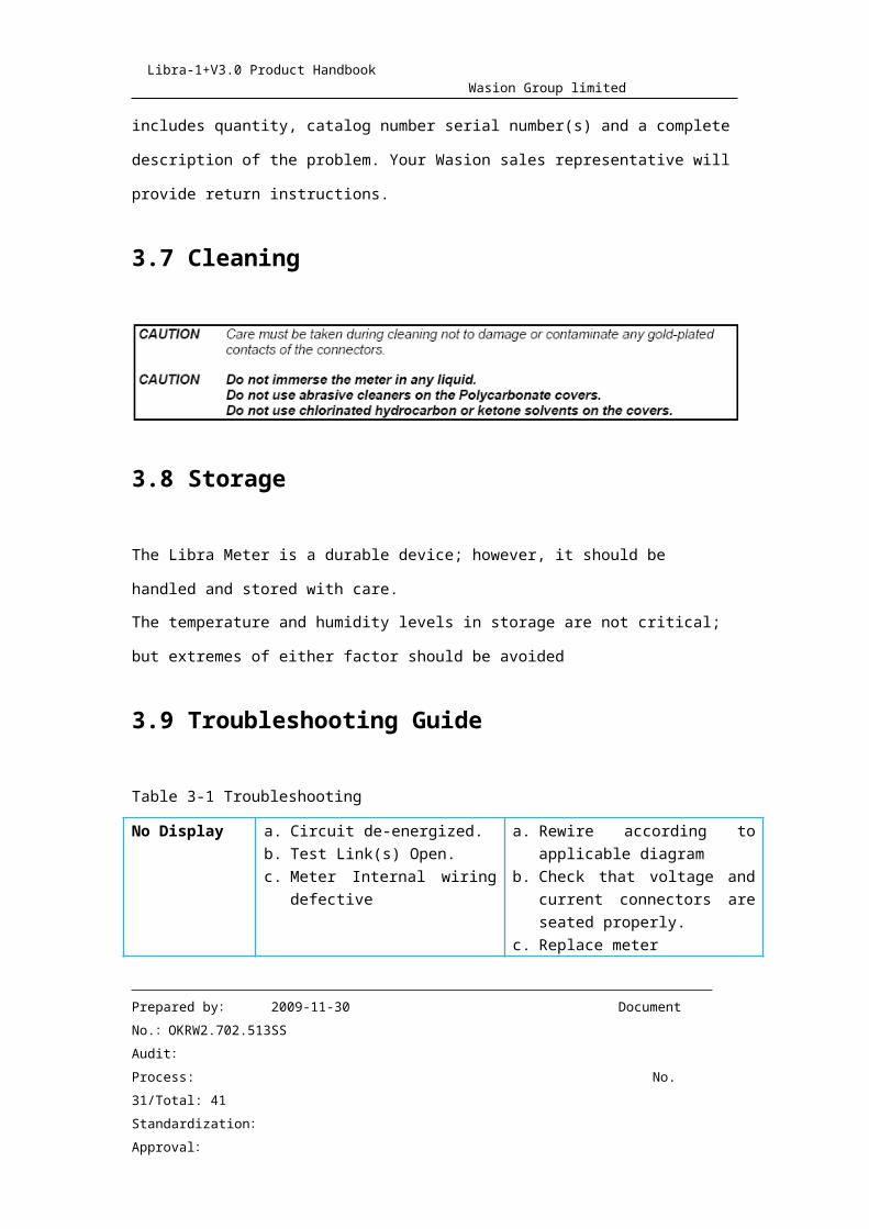
3.7 Cleaning
3.8 Storage
The Libra Meter is a durable device; however, it should be handled and stored with care.
The temperature and humidity levels in storage are not critical; but extremes of either
factor should be avoided
3.9 Troubleshooting Guide
Table 3-1 Troubleshooting
No Display a. Circuit de-energized.b. Test Link(s) Open.c. Meter Internal wiring
defective
a. Rewire according to applicable diagram
b. Check that voltage and current connectors are seated properly.
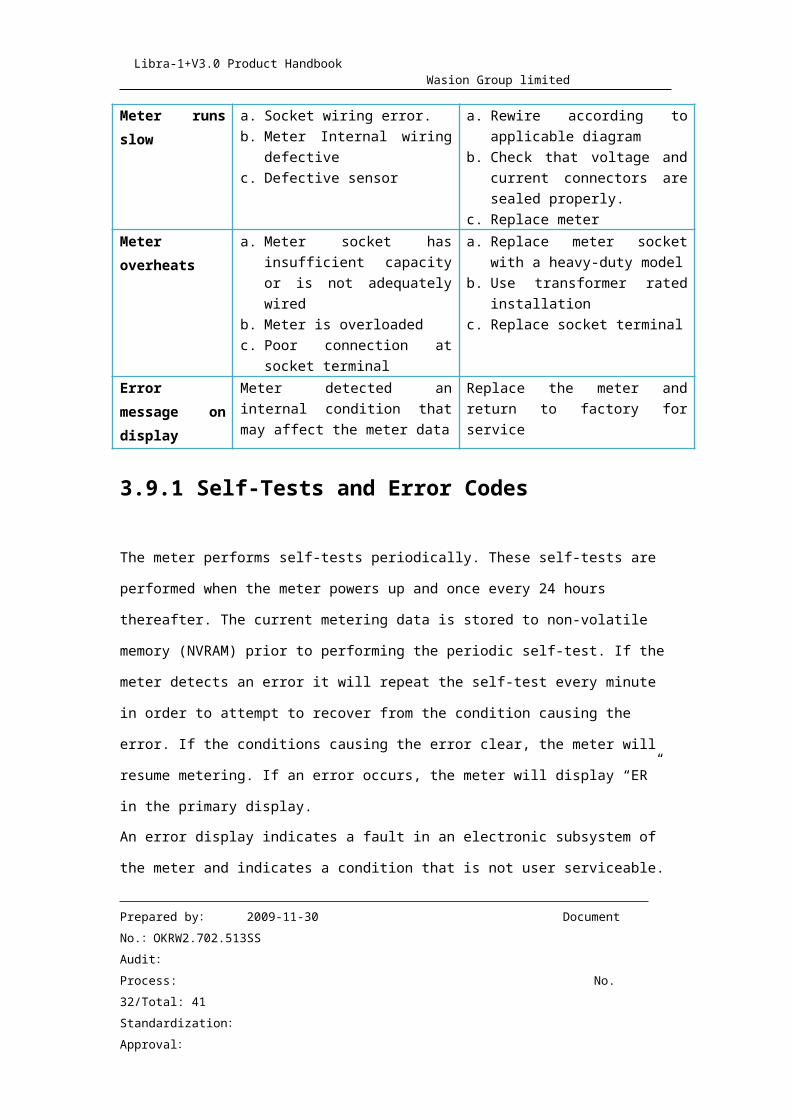
c. Replace meterMeter runs slow
a. Socket wiring error.b. Meter Internal wiring
defectivec. Defective sensor
a. Rewire according to applicable diagram
b. Check that voltage and current connectors are sealed properly.
c. Replace meterMeter overheats
a. Meter socket has insufficient capacity or is not adequately wired
b. Meter is overloaded
a. Replace meter socket with a heavy-duty model
b. Use transformer rated installation
Prepared by: 2009-11-30 Document No.:OKRW2.702.513SS
Audit:Process: No. 26/Total: 34
Standardization:
Approval:
Libra-1+V3.0 Product Handbook Wasion Group limited
c. Poor connection at socket terminal
c. Replace socket terminal
Error message on display
Meter detected an internal condition that may affect the meter data
Replace the meter and return to factory for service
3.9.1 Self-Tests and Error Codes
The meter performs self-tests periodically. These self-tests are performed when the
meter powers up and once every 24 hours thereafter. The current metering data is stored
to non-volatile memory (NVRAM) prior to performing the periodic self-test. If the meter
detects an error it will repeat the self-test every minute in order to attempt to recover from
the condition causing the error. If the conditions causing the error clear, the meter will
resume metering. If an error occurs, the meter will display “ER” in the primary display.
An error display indicates a fault in an electronic subsystem of the meter and indicates a
condition that is not user serviceable.
4.0 Installation Instructions
4.1 General
CAUTION: Do not interchange power and meter module assemblies between meters.
Calibration data stored in meter is particular to a matched power and meter module.
Interchanging these components causes the meter to lose calibration. The meter should
never be disassembled. Failure to observe this practice can result in serious injury or
death.
Prepared by: 2009-11-30 Document No.:OKRW2.702.513SS
Audit:Process: No. 27/Total: 34
Standardization:
Approval:
Libra-1+V3.0 Product Handbook Wasion Group limited
This chapter of the guide give instructions for the proper handling and installation of the
Libra meter.
4.2 Inspection
Perform the following inspections when you receive the meter:
Inspect for obvious damage to the cover, base, and meter assembly.
Be sure the optical connector is free of debris.
Compare the meter and register nameplates to the record card and invoice. Verify
the type, class, voltage, form number, and other pertinent data.
Save the original packing materials.
4.3 Storage
Store the meter in a clean, dry (relative humidity < 50%) environment between -40℃ to+85℃ (-40℉ to +185℉). Avoid prolonged storage (more than one year) at temperatures
above +70℃ (+158℉). Store the meter in the original packing material.
4.4 Unpacking
As with all precision electronic instruments, the meter should be handled with care in
an outdoor environment. Follow these precautions when handling the meter:
Avoid damaging the meter base, cover, reset mechanism (if supplied), and optical
connector (if supplied).
When handling personality modules, grip the circuit board by its edges. Do not touch
the liquid crystal display
Prepared by: 2009-11-30 Document No.:OKRW2.702.513SS
Audit:Process: No. 28/Total: 34
Standardization:
Approval:
Libra-1+V3.0 Product Handbook Wasion Group limited
4.5 Selecting a site
The meter is designed and manufactured to be installed in an outdoor environment, at
operating temperature ranges between -20℃ to +70℃ (-40℉ to +185℉). Operation in
moderate temperatures increases reliability and product life.
4.6 Meter installation
The meter is plugged into a meter socket using standard meter installation practices. The
meter base has current and terminals extending outside from the back of the meter.
These terminals engage with the socket jaws, which are connected to the service lines.
The socket jaws provide heavy contact force with the help of spring. In some heavy-duty
sockets, contact force is provided by a handle or wrench.
On powering-up the meter, verify meter operations by observing the display:
For the first 3 seconds, the LCD display All Segment Test (all display items shown).
If this all segment display is continued after 3 seconds then there is possibly an error
in the installation wiring.
LCD display the software version of the meter for 1 second.
After that, LCD displays the number of digits for Energy.
Verify the expected direction of energy flow on the display Annunciator.
5.0 Site Analysis Guides and Diagram
NOTICE:
These site analyses include basic connection diagrams for identification of metering
installation.
Prepared by: 2009-11-30 Document No.:OKRW2.702.513SS
Audit:Process: No. 29/Total: 34
Standardization:
Approval:
Libra-1+V3.0 Product Handbook Wasion Group limited
Caution: these diagrams are not metering installation guides.
5.1 Form 1S (Self-Contained)
Figure 5.1 2-wire, 1-phase, 1-elementCaution: Actual installation procedures, equipment, and connections must conform to applicable codes and standards.
5.2 Form 2S (Self-Contained)
Figure 5.2 3-wire, 1-phase, 1-elementCaution: Actual installation procedures, equipment, and connections must conform to
Prepared by: 2009-11-30 Document No.:OKRW2.702.513SS
Audit:Process: No. 30/Total: 34
Standardization:
Approval:
Libra-1+V3.0 Product Handbook Wasion Group limited
applicable codes and standards.
5.3 Form 3S (Transformer Rated)
Figure 5.3 2-wire, 1-phase, 1-elementCaution: Actual installation procedures, equipment, and connections must conform to
applicable codes and standards.
5.4 Form 3S (Transformer Rated)
Prepared by: 2009-11-30 Document No.:OKRW2.702.513SS
Audit:Process: No. 31/Total: 34
Standardization:
Approval:
Libra-1+V3.0 Product Handbook Wasion Group limited
Figure 5.4 3-wire, 1-phase, 1-elementCaution: Actual installation procedures, equipment, and connections must conform to
applicable codes and standards
5.5 Form 4S (Transformer Rated)
Prepared by: 2009-11-30 Document No.:OKRW2.702.513SS
Audit:Process: No. 32/Total: 34
Standardization:
Approval:
Libra-1+V3.0 Product Handbook Wasion Group limited
Figure 5.5 3-wire, 1-phase, 1-elementCaution: Actual installation procedures, equipment, and connections must conform to
applicable codes and standards.
5.6 Diagrams
Figure 5.6 diagrams of ANSI C12.10 Internal Connection
Prepared by: 2009-11-30 Document No.:OKRW2.702.513SS
Audit:Process: No. 33/Total: 34
Standardization:
Approval:
Libra-1+V3.0 Product Handbook Wasion Group limited
6.0 Appendix
The Interface between Meter and AMR Module Libra is equipped with two UART port, one is optical port, and the other is AMR port.The AMR port meets to C12.18-1996 and C12.19-1997 standard. This port can beused to communication with inner AMR module, such as RF/PLC/Zigbee etc.
Prepared by: 2009-11-30 Document No.:OKRW2.702.513SS
Audit:Process: No. 34/Total: 34
Standardization:
Approval: