Embed Size (px)
Citation preview

Tested by:
Installer: Please complete the details on the back cover and leave this manual with the homeowner.
Homeowner: Please keep these instructions for future reference.
Liberty® L234 Gas Insert
Owners & Installation Manual
MODELS: L234-NG10 Natural Gas L234-LP10 Propane
Liberty L234 Product Video
- Do not store or use gasoline or other flammable vapors and liquids in the vicinity of this or any other appliance.
- WHAT TO DO IF YOU SMELL GAS • Do not try to light any appliance. • Do not touch any electrical switch: do not use any phone in your building. Leave the building immediately. • Immediately call your gas supplier from a neighbour's phone. Follow the gas supplier's
instructions. • If you cannot reach your gas supplier, call the fire department. Installation and service must be performed by a qualified installer, service agency or the gas supplier.
WARNINGFIRE OR EXPLOSION HAZARDFailure to follow safety warnings exactly could result in seriousinjury, death, or property damage.
919-442f FPI FIREPLACE PRODUCTS INTERNATIONAL LTD. 6988 Venture St., Delta, BC Canada, V4G 1H4 12.02.20

2 | Liberty® L234-10 Direct Vent Gas Insert
| 2
REGENCY GAS FIREPLACE INSERT
TO THE NEW OWNER
Congratulations! You are the owner of a state-of-the-art Gas Insert by Regency.
The L234 Direct Vent Gas Insert has been designed to provide you with all the warmth and charm of a fireplace, at the flick of a switch. The L234-NG10 and L234-LP10 have been approved by Warnock Hersey /Intertek for both safety and efficiency.
As it also bears our own mark, it promises to provide you with economy, comfort and security for many trouble free years to follow. Please take a moment now to acquaint yourself with these instructions and the many features of your Regency Fireplace.
Liberty L234 Product VideoRegency Liberty
Gas Inserts Benefits Video
Liberty® L234-10 Direct Vent Gas Insert | 3
| 3table of contents
Installation
MA Code - CO Detector ................................................5(for the State of Massachusetts only) ............................5For Your Safety ..............................................................7Important Message .......................................................8Gas Pressure Testing ....................................................8Specifications ................................................................8Gas Pressure Testing ....................................................9Installation Into A Solid Fuel Burning Fireplace Or Factory Built Fireplace ..............................................9Before You Start .............................................................9Factory-Built (Metal) Wood-Burning Fireplace Requirements ................................................................9Installation Checklist ....................................................10Materials Required ......................................................10Minimum Fireplace Opening ........................................10Minimum Clearances To Combustibles ........................11Combustible Mantel Clearances ..................................11Venting .........................................................................12Converting from 3" & 3" venting to 3" & 2" ...................13Vent Restrictor Position ...............................................13Flue Liner Installation ..................................................14Gas Connection ..........................................................14Gas Insert Aeration adjustment ...................................15Gas Pipe Pressure Testing ..........................................16SIT 829 Valve Description ...........................................16Conversion from NG to LP...........................................17Optional Brick Panel Installation .................................18Safety screen install ....................................................19Glass door removal/install ...........................................19Log Set Installation ......................................................20Low profile faceplate Installation..................................24Hearth trim Installation ................................................25
Wiring Diagrams ..........................................................26Optional Wall Thermostat ...........................................27Final Check ..................................................................27DC Spark Igniter ..........................................................27Battery Installation .......................................................27First Fire ......................................................................28
Operating Instructions
Operating Instructions .................................................28Lighting Procedure ......................................................28Shutdown Procedure ...................................................28Copy Of Lighting Instruction Plate ...............................29Normal Operating Sounds Of Gas Appliances .........................................29
Maintenance
Maintenance Instructions ............................................30Log Replacement ........................................................30Glass Gasket ...............................................................30General Vent Maintenance ..........................................30Door Glass ..................................................................30Fan Replacement ........................................................31Valve Replacement ......................................................33Gas Maintenance ........................................................35
Parts
Main Assembly ............................................................35
Warranty
Warranty ......................................................................40
This appliance does not have the capability to adjust the fan speed using the supplied remote—even though the remote transmitter allows this function. The appliance fan is controlled by a fan speed controller (rheostat) or on/off switch depending on the model.

4 | Liberty® L234-10 Direct Vent Gas Insert
| 4 safety decalThis is a copy of the labels that accompany each L234 Gas Insert. We have printed a copy of the contents here for your review. The safety label is located on a plate inside the base of the unit visible when the bottom louver is opened. Ensure that the safety label is attached to the unit.
NOTE: Regency units are constantly being improved. Check the label on the unit and if there is a difference, the label on the unit is the correct one.
For the State of Massachusetts, installation and repair must be done by a plumber or gasfitter licensed in the Commonwealth of Massachusetts.
For the State of Massachusetts, flexible con-nectors shall not exceed 36 inches in length.
For the State of Massachusetts, the appli-ances individual manual shut-off must be a t-handle type valve.
The State of Massachusetts requires the installation of a carbon monoxide alarm in accordance with NFPA 720 and a CO alarm with battery back up in the same room where the gas appliance is installed.

Liberty® L234-10 Direct Vent Gas Insert | 5
| 5requirements
5.08: Modifications to NFPA-54, Chapter 10
(2) Revise 10.8.3 by adding the following additional requirements:
(a) For all side wall horizontally vented gas fueled equipment installed in every dwelling, building or structure used in whole or in part for residential purposes, including those owned or operated by the Commonwealth and where the side wall exhaust vent termination is less than seven (7) feet above finished grade in the area of the venting, including but not limited to decks and porches, the following requirements shall be satisfied:
1. INSTALLATION OF CARBON MONOXIDE DETECTORS. At the time of installation of the side wall horizontal vented gas fueled equipment, the installing plumber or gasfitter shall observe that a hard wired carbon monoxide detector with an alarm and battery back-up is installed on the floor level where the gas equipment is to be installed. In addition, the installing plumber or gasfitter shall observe that a battery operated or hard wired carbon monoxide detector with an alarm is installed on each additional level of the dwelling, building or structure served by the side wall horizontal vented gas fueled equipment. It shall be the responsibility of the property owner to secure the services of qualified licensed professionals for the installation of hard wired carbon monoxide detectors
a. In the event that the side wall horizontally vented gas fueled equipment is installed in a crawl space or an attic, the hard wired carbon monoxide detector with alarm and battery back-up may be installed on the next adjacent floor level.
b. In the event that the requirements of this subdivision can not be met at the time of completion of installation, the owner shall have a period of thirty (30) days to comply with the above requirements; provided, however, that during said thirty (30) day period, a battery operated carbon monoxide detector with an alarm shall be installed.
2. APPROVED CARBON MONOXIDE DETECTORS. Each carbon monoxide detector as required in accordance with the above provisions shall comply with NFPA 720 and be ANSI/UL 2034 listed and IAS certified.
3. SIGNAGE. A metal or plastic identification plate shall be permanently mounted to the exterior of the building at a minimum height of eight (8) feet above grade directly in line with the exhaust vent terminal for the horizontally vented gas fueled heating appliance or equipment. The sign shall read, in print size no less than one-half (1/2) inch in size, "GAS VENT DIRECTLY BELOW. KEEP CLEAR OF ALL OBSTRUCTIONS".
4. INSPECTION. The state or local gas inspector of the side wall horizontally vented gas fueled equipment shall not approve the installation unless, upon inspection, the inspector observes carbon monoxide detectors and signage installed in accordance with the provisions of 248 CMR 5.08(2)(a)1 through 4.
(b) EXEMPTIONS: The following equipment is exempt from 248 CMR 5.08(2)(a)1 through 4:
1. The equipment listed in Chapter 10 entitled "Equipment Not Required To Be Vented" in the most current edition of NFPA 54 as adopted by the Board; and
2. Product Approved side wall horizontally vented gas fueled equipment installed in a room or structure separate from the dwelling, building or structure used in whole or in part for residential purposes.
(c) MANUFACTURER REQUIREMENTS - GAS EQUIPMENT VENTING SYSTEM PROVIDED. When the manufacturer of Product Approved side wall horizontally vented gas equipment provides a venting system design or venting system components with the equipment, the instructions provided by the manufacturer for installation of the equipment and the venting system shall include:
1. Detailed instructions for the installation of the venting system design or the venting system components; and
2. A complete parts list for the venting system design or venting system.
(d) MANUFACTURER REQUIREMENTS - GAS EQUIPMENT VENTING SYSTEM NOT PROVIDED. When the manufacturer of a Product Approved side wall horizontally vented gas fueled equipment does not provide the parts for venting the flue gases, but identifies "special venting systems", the following requirements shall be satisfied by the manufacturer:
1. The referenced "special venting system" instructions shall be included with the appliance or equipment installation instructions; and
2. The "special venting systems" shall be Product Approved by the Board, and the instructions for that system shall include a parts list and detailed installation instructions.
(e) A copy of all installation instructions for all Product Approved side wall horizontally vented gas fueled equipment, all venting instructions, all parts lists for venting instructions, and/or all venting design instructions shall remain with the appliance or equipment at the completion of the installation.
MA Code - CO Detector(for the State of Massachusetts only)

6 | Liberty® L234-10 Direct Vent Gas Insert
| 6 dimensions
Shown with Low Profile Faceplate
ALL PICTURES / DIAGRAMS SHOWN THROUGHOUT THIS MANUAL ARE FOR ILLUSTRATION PURPOSES ONLY.ACTUAL PRODUCT MAY VARY DUE TO PRODUCT ENHANCEMENTS.

Liberty® L234-10 Direct Vent Gas Insert | 7
| 7installation
CLOTHING OR OTHER FLAMMABLE MATERIAL SHOULD NOT BE PLACED ON OR NEAR THE APPLIANCE.
CHILDREN AND ADULTS SHOULD BE ALERTED TO THE HAZARDS OF HIGH SURFACE TEMPERATURES, ESPE-CIALLY THE FIREPLACE GLASS, AND SHOULD STAY AWAY TO AVOID BURNS OR CLOTHING IGNITION.
INSTALLATION AND REPAIR SHOULD BE DONE BY AN AUTHORIZED SERVICE PERSON. THE APPLIANCE SHOULD BE INSPECTED BEFORE USE AND AT LEAST ANNUALLY BY A PROFESSIONAL SERVICE PERSON. MORE FREQUENT CLEANING MAY BE REQUIRED DUE TO EXCESSIVE LINT FROM CARPETING, BEDDING MATERIAL, ETC. IT IS IMPERATIVE THAT CONTROL COMPARTMENTS, BURNERS AND CIRCULATING AIR PASSAGEWAYS OF THE APPLIANCE BE KEPT CLEAN.
DUE TO HIGH TEMPERATURES, THE APPLIANCE SHOULD BE LOCATED OUT OF TRAFFIC AND AWAY FROM FURNITURE AND DRAPERIES.
WARNING: FAILURE TO INSTALL THIS APPLIANCE CORRECTLY WILL VOID YOUR WARRANTY AND MAY CAUSE A SERIOUS HOUSE FIRE.
YOUNG CHILDREN SHOULD BE CARE-FULLY SUPERVISED WHEN THEY ARE IN THE SAME AREA AS THE APPLI-ANCE. TODDLERS, YOUNG CHILDREN AND OTHERS MAY BE SUSCEPTIBLE TO ACCIDENTAL CONTACT BURNS. A PHYSICAL BARRIERS IS RECOMMEND-ED IF THERE ARE AT RISK INDIVIDUAL IN THE HOUSE. TO RESTRICT ACCESS TO A FIREPLACE OR STOVE, INSTALL AN ADJUSTABLE SAFETY GATE TO KEEP TODDLERS, YOUNG CHILDREN AND OTHER AT RISK INDIVIDUALS OUT OF THE ROOM AND AWAY FROM HOT SURFACES.
FOR YOUR SAFETY
This appliance requires air for proper combustion. Always provide adequate combustion and ventilation air. Follow instructions and information in CSA B149.1 (in Canada) or the National Fuel Gas Code ANS Z223.1/NFPA (in the USA), regarding requirements for combustion and ventilation air.
A BARRIER DESIGNED TO REDUCE THE RISK OF BURNS FROM THE HOT VIEWING GLASS IS PROVIDED WITH THIS APPLIANCE AND SHALL BE INSTALLED FOR THE PROTECTION OF CHILDREN AND OTHER AT-RISK INDIVIDUALS
IF THE BARRIER BECOMES DAMAGED, THE BARRIER SHALL BE REPLACED WITH THE MANUFACTURER'S BARRIER FOR THIS APPLIANCE.
ANY SAFETY SCREEN, GUARD, OR BARRIER REMOVED FOR SERVICING AN APPLIANCE MUST BE REPLACED PRIOR TO OPERATING THE APPLIANCE.
8 | Liberty® L234-10 Direct Vent Gas Insert
| 8 installation
IMPORTANT MESSAGE SAVE THESE INSTRUCTIONS
The Regency Direct Vent Gas Insert must be installed in accordance with these instructions. Carefully read all the instructions in this manual first. Consult the building authority having jurisdiction to determine the need for a permit prior to starting the installation.
NOTE: Failure to follow the instructions could cause a malfunction of the heater which could result in death, serious bodily injury, and/or property damage. Failure to follow these instructions may also void your fire insurance and/or warranty.
GAS PRESSURE TESTING
The appliance must be isolated from the gas supply piping system by closing its individual manual shut off valve during any pressure testing of the gas supply piping system at test pressures equal to or less than1/2 psig. (3.45 kPa).
SPECIFICATIONS
At pressures over 1/2 psig, the pipe to the unit must be disconnected.Gas Input Capacity: Natural Gas 23,500 Btu/h Propane 21,500 Btu/hMin. Input: Natural Gas 12,500 Btu/h Propane 11,000 Btu/h
Fuels: Approved for use with both natural gas, and propane. Approved as is for use at 0' to 4,500' (0-1370m).
Electrical: 120V A.C. system.Circulation Fan: Variable speed, 127 CFM.Log Set: Ceramic fibre, 6 per set.Vent System: 3" co-linear aluminum flex or 2" intake with 3" exhaust.
General Safety Information
1) The appliance installation must conform with local codes or in the absence of local codes, with CAN/CSA B149.1 (in Canada) or the National Fuel Gas Code ANSI Z223.1 NFPA 54 in the U.S.A. This appliance should be installed by a qualified gas fitter technician only.
2) Installation and repair should be done by a qualified service person.
3) The appliance should be inspected before use and at least annually by a professional service person. More frequent cleaning may be required due to excessive lint from carpeting, bedding material, animal hair, etc. It is imperative that control compartments, burners and circulating air passageways of the appliance be kept clean.
4) See general construction and assembly instructions. This appliance may only be installed in a vented, noncombustible fireplace.
5) This appliance is Listed for bedroom installations when used with a Listed Millivolt Thermostat. Some areas may have further requirements, check local codes before installation.
6) Always connect this appliance to a vent system vent that is run (or routed) to the outside of the building envelope. Never vent to another room or inside a building. Make sure that the vent is properly sized and is of adequate height to provide the proper draft.
7) Inspect the venting system annually for blockage and any signs of deterioration.
8) Any glass removed for servicing must be replaced prior to operating the appliance.
9) WARNING: Failure to position the parts in accordance with the diagrams in this manual or failure to use only parts specifically approved with this appliance may result in property damage or personal injury.
10) To prevent injury, do not allow anyone who is unfamiliar with the operation to use the fireplace.
Installer must mechanically attach the supplied label to the inside of the firebox of the fireplace into which the gas fireplace insert is installed.
"WARNING: This fireplace has been converted for use with a gas fireplace insert only and cannot be used for burning wood or solid fuels unless all original parts have been replaced, and the fireplace re-approved by the authority having jurisdiction."
Liberty® L234-10 Direct Vent Gas Insert | 9
| 9installation
GAS PRESSURE TESTING
The appliance must be isolated from the gas sup-ply piping system by closing its individual manual shut off valve during any pressure testing of the gas supply piping system at test pressures equal to or less than 1/2 psig. (3.45 kPa).
INSTALLATION INTO A SOLID FUEL BURNING FIREPLACE OR FACTORY BUILT FIREPLACE
The L234 Gas Inserts have been tested and ap-proved to be vented into any masonry fireplace or approved solid fuel burning factory built fireplace that will allow the insert to physically fit into the firebox. Refer to "Minimum Fireplace Dimensions" section for minimum fireplace clearances.
If the factory built fireplace* height is too low for your Insert, you may remove the smoke baffle plate, damper, refractory (firebricks), glass doors, screen rails, screen mesh and log grates from the factory built fireplace as long as these items are saved and are reinstalled in the event that the Insert is removed. The fireplace flue damper can be fully blocked open or removed for installation of the gas fireplace insert.
Smoke shelves, shields and baffles may be removed if attached by mechanical fasteners. If any part is removed it must not weaken the structural integrity of the factory built fireplace.
The fireplace and fireplace chimney must be clean and in good working order and constructed of non- combustible materials.
The surround panels should not seal ventilation openings on the fireplace.
Chimney clean outs should fit properly.
NOTE: Any alterations made to the listed solid fuel burning factory built fireplace may void the listing of the fireplace.Cutting any sheet metal part of the fireplace, in which the gas fireplace insert is to be installed is prohibited.*Check with your local inspector before commencing with this installation.
Installer must mechanically attach the supplied label to the inside of the firebox of the fireplace into which the gas fireplace insert is installed.
"WARNING: This fireplace has been converted for use with a gas fireplace insert only and cannot be used for burning wood or solid fuels unless all original parts have been replaced, and the fireplace re-approved by the authority having jurisdiction."
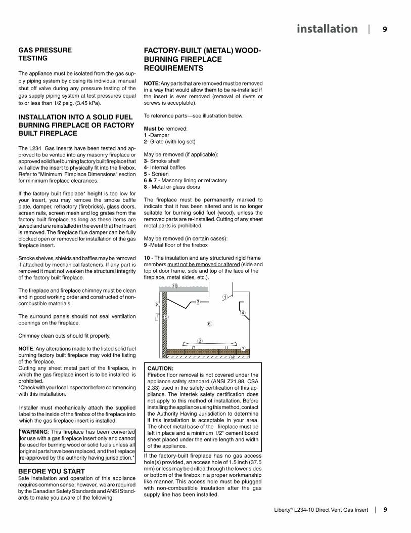
FACTORY-BUILT (METAL) WOOD-BURNING FIREPLACE REQUIREMENTS
NOTE: Any parts that are removed must be removed in a way that would allow them to be re-installed ifthe insert is ever removed (removal of rivets or screws is acceptable).
To reference parts—see illustration below.
Must be removed:1 -Damper2- Grate (with log set)
May be removed (if applicable):3- Smoke shelf4- Internal baffles5 - Screen6 & 7 - Masonry lining or refractory8 - Metal or glass doors
The fireplace must be permanently marked to indicate that it has been altered and is no longer suitable for burning solid fuel (wood), unless the removed parts are re-installed. Cutting of any sheet metal parts is prohibited.
May be removed (in certain cases):9 -Metal floor of the firebox
10 - The insulation and any structured rigid framemembers must not be removed or altered (side andtop of door frame, side and top of the face of thefireplace, metal sides, etc.).
If the factory-built fireplace has no gas access hole(s) provided, an access hole of 1.5 inch (37.5 mm) or less may be drilled through the lower sides or bottom of the firebox in a proper workmanship like manner. This access hole must be plugged with non-combustible insulation after the gas supply line has been installed.
CAUTION: Firebox floor removal is not covered under the appliance safety standard (ANSI Z21.88, CSA 2.33) used in the safety certification of this ap-pliance. The Intertek safety certification does not apply to this method of installation. Before installing the appliance using this method, contact the Authority Having Jurisdiction to determine if this installation is acceptable in your area. The sheet metal base of the fireplace must be left in place and a minimum 1/2" cement board sheet placed under the entire length and width of the appliance.
BEFORE YOU STARTSafe installation and operation of this appliance requires common sense, however, we are required by the Canadian Safety Standards and ANSI Stand-ards to make you aware of the following:

10 | Liberty® L234-10 Direct Vent Gas Insert
| 10 installation11) Due to high temperatures, the appliance
should be located out of high traffic areas and away from furniture and draperies. Children and adults should be alerted to the hazards of high surface temperatures, especially the fireplace glass, and should stay away to avoid burns or clothing ignition. Young children should be carefully supervised when they are in the same room as the appliance. Clothing or other flammable material should not be placed on or near the appliance.
INSTALLATION CHECKLIST
Before installing vent system ensure that the damper plate is open and secure to prevent the damper plate from falling down and crushing the liner.
The Regency Gas Insert is installed as listed below.
1) Check all clearances to combustibles. Refer to the following sections where applicable:
a. Minimum Clearances to Combustibles. b. Combustible Mantel Clearances c. Mantel Clearances
2) Make the gas connection. Refer to the "Gas Connection" section.
3) Install the 3" x 3" or 3" x 2" flue liner to the sliding connector plate. Refer to the "Flue Liner Installation" section.
4) Slide the unit half way into the fireplace.
5) Pull the vent connector plate through the tapered brackets and fasten to the front plate. Refer to the "Flue Liner Installation" section.
6) Install 4AA batteries into receiver. Hook receiver to wire marked receiver, this will enable operation of the appliance manually when position in "ON" position.
7) Slide the unit fully into the fireplace.
Emissions from burning wood or gas could contain chemicals known to the State of California to cause cancer, birth defects or other reproductive harm.
8) Test gas pressure, refer to the "Gas Pipe Pressure Testing" section. Check aeration system, refer to "Gas Insert Aeration Systems" section.
9) Install standard and optional features. Refer to the following sections where applicable:
a. Brick Panels b. Log Installation c. Faceplate d. Optional Hearth Trim e Remote Control
f. Wall Thermostat
10) Final check. Refer to the "Final Check" section. Before leaving this unit with the customer, the installer must ensure that the appliance is firing correctly. This includes:
a) Clocking the appliance to ensure the correct firing rate.
b) Adjusting the primary air, if required, to ensure that the flame does not carbon. Refer to the "Gas Insert Aeration System" section.
c) Ensuring that the appliance is venting correctly.
MATERIALS REQUIRED
No electrical power supply is required for the gas control to operate. A 120 Volt AC power cord is hooked up to the fan. Plug the 3 wire cord into a suitable receptacle. Do not cut the ground terminal off under any circumstances. When connected with 120 volts, the appliance must be electrically grounded in accordance with local codes, current version of the Canadian Electrical Code CSA C22.1 (in Canada) or in the absence of local codes, with the National Electrical Code ANSI/NFPA 70.
MINIMUM FIREPLACE OPENING
The minimum fireplace opening for the L234 gas fireplace insert is shown in the following diagrams:
WARNING: Electrical Grounding
InstructionsThis appliance is equipped with a three pronged (grounding) plug for your protection against shock hazard and should be plugged directly into a properly grounded three-prong receptacle. Do not cut or remove the grounding prong from this plug.

Liberty® L234-10 Direct Vent Gas Insert | 11
| 11installation
MINIMUM CLEARANCES TO COMBUSTIBLES
Side Walls A 8" (203 mm)*/*** Ceiling B 56" (1422 mm)
Min. Mantel Height C 21" (533 mm) see Diagram 1 Max. Mantel Depth D 12" (305 mm) see Diagram 1
Alcove Width E 60" (1524 mm)Alcove Depth F 36" (914 mm)
**Hearth Height- G 1-1/2" (38 mm) MinimumNon combustibleHearth Width H 28" (686 mm)Hearth Depth I 12" (305 mm)
* Alcove side wall must have a minimum of 8" clearance.**Note: A 1-1/2" high non-combustible hearth is required if unit is not
raised off the ground a minimum of 4"***Measured from edge of glass frame.(J) Glass Frame Width (Reference Only): 25'' (635mm)
COMBUSTIBLE MANTEL CLEARANCES
Because of the extreme heat this fireplace emits, the mantel clear-ances are critical. Combustible mantel clearances from top of door frame are shown in the diagram below. Mantel may be installed anywhere in the shaded area or higher.
Note: A non-combustible mantel may be installed at a lower height.
Note: Ensure the paint that is used on the mantel and the facing is “heat resistant” or the paint may discolour.
I
D
E
F
H
G
A
B
C
J
56”to ceiling
17” (432mm)to floor
12” Mantel
1” Mantel
4” Mantel
30”
Top of Door Frame
21”
23”
22
24 Combustible
Non-combustible
Unless otherwise stated the clearances listed below are Minimum distances to combustible materials. Please Note: A major cause of chimney related fires is due to a failure to maintain required clearances (air space) to combustible materials. It is of the greatest importance that this insert and vent system be installed only in accordance with these instructions.
Faceplate
CombustibleFlooring
Mantel
C
12" Max.D
Top ofDoor Frame
Faceplate
12” Min.
Hearth
Mantel
C
12" Max.D
Existing orNon-Combustible Hearth
Top ofDoor Frame
4” minG
INSTALLATION WITH NON-COMBUSTIBLE HEARTH IN FRONT INSTALLATION WITH COMBUSTIBLE
FLOORING IN FRONT
Faceplate
CombustibleFlooring
Mantel
C
12" Max.D
Top ofDoor Frame
Faceplate
12” Min.
Hearth
Mantel
C
12" Max.D
Existing orNon-Combustible Hearth
Top ofDoor Frame
4” minG
Diagram 1
No hearth required if the unit is raised 4" (102mm) or more.
**

12 | Liberty® L234-10 Direct Vent Gas Insert
| 12 installation
THE APPLIANCE MUST NOT BE CONNECTED TO A CHIMNEY FLUE SERVING A SEPARATE SOLID FUEL BURNING APPLIANCE.
This appliance is designed to be attached to two 3" (76mm) co-linear aluminium flex running the full length of the chimney. The flue length must be a minimum length of 8' (2.44m) and a maximum of 35' (10.7m). Periodically check that the vent is unrestricted.
Masonry chimneys may take various contours which the flexible liner will accommodate. However, keep the flexible liner as straight as possible, avoid unnecessary bending.
VENTING
Alternative Approved Venting Components*46DVA-VC Vertical Termination Cap46DVA-VCH High Wind Cap46DVA-GK 3" Co-linear Adaptor with flashing
In areas of consistently high winds, we recommend using the Simpson Dura-Vent System 46DVA-GK adapter and 46DVA-VCH high-wind cap.The Air Intake pipe must be attached to the inlet air collar of the termination cap.
*NOTE: Simpson Duravent can only be used with 3" liners.
INSTALLATION WITH 3" & 3" LINERS
Part # Description948-305 3" Flex - 35 ft. (intake & exhaust)946-529 Regency Co-linear DV Vertical Termination Cap & Flashing
The L234 is also approved for use with a 2" liner for air intake and a 3" liner for exhaust. This would be suitable for a Class A wood burning chimney with a minimum 6" round flue.
The chimney must be lined with one 2" diameter liner for intake and one 3" diameter liner for exhaust. The minimum vent length is 8' and maximum is 35'.
INSTALLATION WITH 3" & 2" LINERS
Part # Description948-305 3" Flex - 35 ft. (exhaust)948-316 2" Flex - 35 ft. (intake)946-582 Regency Co-l inear DV Ver t ical Terminat ion Cap, Flashing & 2" Collar
Vent Run Vent Restrictor
PositionBurner Aeration
Setting
8' to 20' 1" 3/16"
20' to 35' 3/4" 3/16"
NOTE: See instructions in the "Vent Restrictor Position" section on positioning of the vent restrictor.
Vent Run Vent Restrictor
PositionBurner Aeration
Setting
8' to 20' 1" 3/16"
20' to 35' 1" 1/8"
NOTE: See instructions in the "Vent Restrictor Position" section on positioning of the vent restrictor.

Liberty® L234-10 Direct Vent Gas Insert | 13
| 13installation
CONVERTING FROM 3" & 3" VENTING TO 3" & 2"
1) Remove the top plate from the unit by undoing the screw at the front of the firebox and slide out towards the back of the unit.
VENT RESTRICTOR POSITION
The Vent Restrictor plate is located on the inside top of the firebox.
To change the vent restrictor position, refer to the instructions below;
1) Remove the glass door.
2) Remove brick panels if installed.
3) Remove the 4 screws that hold the vent restrictor plate in place.
2) Remove the 3" collar from the top plate by undoing the 4 screws. NOTE: The screws are secured from the underside of the top plate.
Underside of Top Plate
3) Secure the 2" collar to the top plate using 4 screws in place of the 3" collar.
4) Re-install the top plate to the unit.
Top Plate with 2" Collar shown on Unit
4) Adjust the vent restrictor plate to the required vent restrictor position.
5) Once the vent restrictor plate is in the required position, secure using the 4 screws removed from step 3.
6) Re-install brick panels if removed.
7) Re-install glass door.
Factory Set at 1"
1"‹ ›
Adjusted to 3/4"
3/4"‹ ›

14 | Liberty® L234-10 Direct Vent Gas Insert
| 14 installation
GAS CONNECTION
GAS CONNECTION WARNING:Only persons licensed to work with gas piping may
make the necessary gas connections to this appliance.
1) When the appliance is to be installed into either an existing masonry chimney system or factory built fireplace, thoroughly clean the chimney before installation.
2) A 3/8" NPT gas supply pipe must be brought near the inlet hole. The valve inlet is on the right side of the unit.
3) Locate the center point where the vent will pass through the chimney above the appliance. Move the appliance into the exact location where it is to be installed. Ensure that the Insert is level.
NOTE: This unit is equipped with a heat sensor thermodisc which will prevent the blower from operating until the unit reaches the correct temperature.
5) Install flashing.
6) Insert both liners into chimney, passing through the damper opening.
7) Install termination cap.
8) Connect the marked end of the liner to the exhaust collar of the vent connector plate marked with an "E", seal connection with high temperature silicone. Secure with gear clamp or screws.
NOTES: 1) Final gas connection should be made after unit is in place to avoid
damage to the liner when pushing the unit into position.
2) Mill-pac may be used instead of high temperature silicone and screws may be used instead of gear clamps at connections of liner to inlet and vent collars.
9) Connect the 2nd liner to the intake collar, seal connection with high temperature silicone. Secure with gear clamp or screws.
10) Align vent connector plate with guides on unit.
11) Slide unit into masonry opening, while ensuring that the slot at the rear of the connector plate mates up with the hold down plate on the unit.
12) Secure with screw.
FLUE LINER INSTALLATION
1) Cut the flex liner as required. 2) Mark the end of one liner with an "E" to indicate exhaust.
3) Connect the other end of the above liner to the exhaust side of the termination cap, seal connection with high temperature silicone. Secure with gear clamp or screws.
4) Connect the 2nd liner to the inlet side of the cap, seal connection with high temperature silicone. Secure with gear clamp or screws.

Liberty® L234-10 Direct Vent Gas Insert | 15
| 15installation
GAS INSERT AERATION ADJUSTMENT
The burner aeration is factory set but may need adjusting due to either the local gas supply or altitude. Open the air shutter for a blue flame or close for a more yellow flame. To access burner aeration–see Steps below.
CAUTION: Carbon will be produced if the air shutter is closed too much.
Minimum Air Shutter Openings
Vent Run Burner Aeration
Setting
3" x 3"
8' to 20'NG: 3/16"LP: 3/16"
20' to 35'NG: 3/16"LP: 3/16"
3" x 2"
8' to 20'NG: 3/16"LP: 3/16"
20' to 35'NG: 1/8"LP: 1/8"
Note: Any damage due to carboning resulting from improperly setting the aeration controls is NOT covered under warranty.
Note: Aeration Adjustment should only be performed by an authorized Regency Installer at the time of installation or service.
1. Remove the outer faceplate.
2. Remove the safety screen.
3. Remove the glass door.
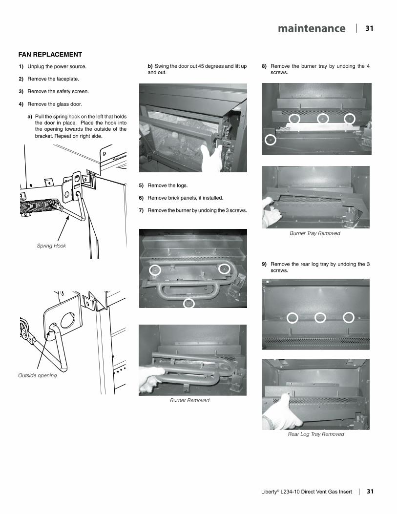
a) Pull the spring hook on the left that holds the door in place. Place the hook into the opening towards the outside of the bracket. Repeat on right side.
b) Swing the door out 45 degrees and lift up and out.
4. Remove the logs.
5. Remove brick panels, if installed.
6. Remove the burner by undoing the 3 screws.
7. Make necessary aeration adjustment - reverse Steps 6-1.
Burner Removed
Spring Hook
Outside opening

16 | Liberty® L234-10 Direct Vent Gas Insert
| 16 installation
GAS PIPE PRESSURE TESTING
The appliance must be isolated from the gas supply piping system by closing its individual manual shut-off valve during any pressure testing of the gas supply piping system at test pressures equal to or less than 1/2 psig. (3.45 kPa). Disconnect piping from valve at pressures over 1/2 psig.
The manifold pressure is controlled by a regulator built into the gas control, and should be checked at the pressure test point.
NOTE: To properly check gas pressure, both inlet and manifold pressures should be checked using the valve pressure ports on the valve.
1) Make sure the valve is in the "OFF" position.
2) Loosen the "IN" and/or "OUT" pressure tap(s), turning counterclockwise with a 1/8" wide flat screwdriver.
3) Attach manometer to "IN" and/or "OUT" pressure tap(s) using a 5/16" ID hose.
4) Light the pilot and turn the valve to "ON" position.
5) The pressure check should be carried out with the unit burning and the setting should be within the limits specified on the safety label.
6) When finished reading manometer, turn off the gas valve, disconnect the hose and tighten the screw (clockwise) with a 1/8" flat screwdriver. Note: Screw should be snug, but do not over tighten.
SIT 829 VALVE DESCRIPTION
1) Gas on/off knob2) Electronically Operated Hi/Lo3) Pilot Adjustment4) Thermocouple Connection - option5) Outlet Pressure Tap6) Inlet Pressure Tap7) Pilot Outlet8) Main Gas Outlet9) Alternative TC Connection Point

Liberty® L234-10 Direct Vent Gas Insert | 17
| 17installation
CONVERSION FROM NG TO LP
919-465 11.30.161
L234-10 / L234-11
CONVERSION KIT #537-969 FROM NG TO LP
LP Conversion Kit Contains:
Qty. Part # Description1 910-037 LP Pilot Orifi ce1 904-163 Orifi ce #541 904-529 5/32" Allen Key1 910-582 Stepper Motor1 918-590 LP Conversion Decal1 908-528 Red Propane Label1 919-465 Instruction Sheet
THIS CONVERSION MUST BE DONE BY A QUALIFIED GAS FITTER, IF IN DOUBT DO NOT DO THIS CONVERSION!!
LP Conversion Instructions
1. Shut off gas and electrical supply to the unit.
2. Remove the faceplate.
3. Remove the safety screen and glass door - see manual for detailed instructions.
4. Remove the logs if installed.
5. Remove the brick panels if installed.
6. Remove the burner by undoing the 3 screws.
Burner Removed
7. Remove the burner tray by undoing the 4 screws.
Burner Tray Removed
8. Remove burner orifi ce with a 1/2" wrench and discard.
9. Install the new LP burner orifi ce stamped #54 and tighten.
10. Pull off the pilot cap to expose the pilot orifi ce.
11. Unscrew the pilot orifi ce with the supplied allen key and replace it with the LP pilot orifi ce in the kit and re-install the pilot cap.
12. Remove the pilot/on/off extension knob by pulling the knob towards you. Remove NG stepper motor by removing 3 screws in loca-tions shown below–replace with LP stepper motor, secure in place with 3 screws.
Remove NG Stepper motor and replace with LP Stepper motor
13. Reinstall the pilot/on/off extension knob removed from step 12. Check for gas leaks with a proper soapy solution or leak detector.
14. Check inlet and outlet pressures. Refer to "Gas Pipe Pressure Testing" section of the manual.
15. Attach the label "This unit has been con-verted to LP" near or on top of the serial # decal.
16. Replace yellow "NG" label with red "LP" label.
17. Reverse Steps 8 - 1.
NOTE: before re-installing burner, check the LP aeration settings.
18. Check operation of fl ame control.
19. Check for proper fl ame appearance and glow on logs.

18 | Liberty® L234-10 Direct Vent Gas Insert
| 18 installation
OPTIONAL BRICK PANEL INSTALLATION
918-686 04/13/071
L234
BRICK PANEL INSTALLATION
1) Carefully remove the brick panels from the box and unwrap them.
2) Insert the back brick panel by carefully placing it against the back wall of the fi rebox and rest it on the rear log tray.
Back Brick Panel
Rear Log Tray
3) Slide the right side brick panel into position and secure in place using the brick clip. Repeat for left side.
Brick Clip
Right Side Brick Panel
Completed Brick Panel Installation
NOTE: Brick Panels are mandatory when using Optional Remote

Liberty® L234-10 Direct Vent Gas Insert | 19
| 19installation
SAFETY SCREEN INSTALL GLASS DOOR REMOVAL/INSTALL
1. Remove the glass door.
a) Pull the spring hook on the left that holds the door in place. Place the hook into the opening towards the outside of the bracket. Repeat on right side.
b) Swing the door out 45 degrees and lift up and out.
Spring Hook
Tab on screen assembly
Folded Tab on screen assembly
Tab on glass door
Tab on glass door
1. Slide the folded tab on the screen assembly over the tab on the glass door (left and right sides).
2. Install screen assembly and glass door together and secure with spring hooks on left and right side. To remove see "Glass Door Removal" instructions.
Outside opening
2. To reinstall–reverse steps.
Spring Hook

20 | Liberty® L234-10 Direct Vent Gas Insert
| 20 installation
LOG SET INSTALLATION
918-674a 01/03/081
L234
Log kit (Part # 536-930) contains the following pieces: a) 2-711 Rear Log b) 2-712 Center Log c) 2-713 Left Log d) 2-714 Front Log e) 2-715 Top Left Log f) 2-716 Top Right Log g) Embers (supplied with packaged manual)h) 946-669 Platinum Embers (supplied with packaged manual)
LOG SET INSTALLATION
2-713
2-716
2-712
2-715
2-711
2-714
2-711
1) Carefully remove the logs from the box and unwrap them. The logs are fragile, handle with care - do not force into position.
2) Fit log 2-711 into the pins on the rear log tray.
2-711
3) Place log 2-714 on the base of the fi rebox in front of the burner.
2-714
4) Fit log 2-712 into the pins on the middle of the burner.
2-712
Read the instructions below carefully and refer to the images. Dangerous operating conditions may occur if the logs are not positioned in their correct locations. If the logs are broken do not use the unit until they are replaced. Broken logs can interfere with the pilot operation.

Liberty® L234-10 Direct Vent Gas Insert | 21
| 21installation
918-674a 01/03/082
L234
5) Fit the left side of log 2-713 into the pin on log 2-714 and rest the right side of the log on the burner plate pushing it against the tab.
2-712
2-713
2-714
2-713
6) Place log 2-715 into the pin on log 2-712 and rest the right end of the log on the notch in log 2-713.
2-715
2-712
Notch
2-713
2-712
Tab

22 | Liberty® L234-10 Direct Vent Gas Insert
| 22 installation
918-674a 01/03/083
L234
7) Place embers on the right side of the burner as shown. 8) Fit log 2-716 into the pin on log 2-712.
Right side of Burner
2-713
2-716
2-712
Also place a few embers along the burner tube next to log 2-713.
Separate platinum embers and place on and around the embers. Avoid stacking platinum embers.

Liberty® L234-10 Direct Vent Gas Insert | 23
| 23installation
918-674a 01/03/084
L234
Completed Log Set Installation
2-711
2-716
2-715 2-712
2-713 2-714

24 | Liberty® L234-10 Direct Vent Gas Insert
| 24 installation
LOW PROFILE FACEPLATE INSTALLATION
919-475 12.08.161
L234
LOW PROFILE FACEPLATE INSTALLATION
2. Position faceplate backer ( and spacer, if required) behind the flange on the unit and secure with 5 screws in location shown below.
1. * If no spacer required–proceed to Step 2. If optional spacer is required, secure the faceplate backing to the spacer with 2 screws in locations shown below. Attach faceplate backing and spacer to unit together as shown in Step 2.
3. Install the receiver into the bracket located on the left side of the backing plate. The receiver is pre-wired to the appliance. Tuck all wires into bracket. See wiring diagram for details.
5. Install the outer faceplate by hooking on to the brackets on the face-plate backing.
6. To remove–reverse steps.
Tab on screen assembly
Tab on glass door
4. Install safety screen over glass door by opening glass door and slid-ing tab of safety screen over tab of glass door as shown below, then install door and screen together. For further details see manual.
Plug in receiver
Fan wire through grommet

Liberty® L234-10 Direct Vent Gas Insert | 25
| 25installation
HEARTH TRIM INSTALLATION
919-477 11.03.141
OPTIONAL HEARTH TRIM
1) Align the screw holes on the hearth trim brackets with the screw holes on the lower legs of the faceplate backing. Secure in place using 1 screw through hearth trim bracket and lower leg of facepalte backing on each side as shown in Diagram 1.
a) TheHearthTrimcanbeadjusted tocustomfitan installationbypulling apart the top piece from the bottom piece.
b) Cut the top of the bottom piece of the hearth trim to the appropriate height using a metal cutting blade.
NOTE: The tab bends at the back of the top piece of the hearth trim should be used as the measuring point to the hearth to measure the height required.
c) Reattachthetoppieceofthehearthtrimtothecutbottompiecebyfittinginplace.
Customize Hearth Trim:
Hearth Trim Installation:
Completed Hearth Trim Installation:
Diagram 1
2) Attach the supplied brackets to the top of the hearth trim with 2 screws. Note: orientation of brackets is different when using spacer.
3) Install the hearth trim through the lower legs of the faceplate backer and spacer together.
4) Install outer faceplate.
Bracket in correct position for use with spacer
Bracket in correct position for use without spacer
Install hearth trim with faceplate backer and spacer together - same location as in Step 1
Diagram 2
Diagram 3
Diagram 4

26 | Liberty® L234-10 Direct Vent Gas Insert
| 26 installation
WIRING DIAGRAMS
This heater does not require a 120V A.C. supply for operation. However, a 120V A.C. power supply is needed for the fan/blower operation.
Caution: Ensure that the wires do not touch any hot surfaces and are away from sharp edges.
WARNING: Electrical Grounding InstructionsThis appliance is equipped with a three pronged
(grounding) plug for your protection against shock hazard and should be plugged directly into a properly grounded three-prong receptacle. Do not cut or remove the grounding prong from this
plug.CAUTION: Label all wires prior to disconnection when servicing controls. Wiring errors can cause improper and dangerous operation.
ENGLI
SH
REMOTE
TP
TH
TPTHGreenWhite
Red
Black
(+) (-)
9
Ground
Neutral
Live Bla
ck
BlackRed
Minimum ConvectionAir Temp. Switch
ON OFF
Rotary SpeedControl
120V AC60 Hz
Green
GroundFan
Lockwasher
Fan ground
Power cord
ground wire
Star washer
Nut
Nut
#8 Ground Lug
Star washer
DCSpark Box
To Electrode
To Electrode
Thermostat(Optional)(Millivolt)

Liberty® L234-10 Direct Vent Gas Insert | 27
| 27installation
OPTIONAL WALL THERMOSTAT
A wall thermostat may be installed if desired, follow the wiring diagram below. Note: the wires are connected to the "TH" on the gas valve. Use the table below to determine the maximum wire length. Regency offers an optional programmable thermostat but any 250-750 millivolt rated non-anticipator type thermostat that is CSA, ULC or UL approved may be used.
It is recommended that the thermostat be installed on an interior wall.
FINAL CHECK
Before leaving this unit with the customer, the installer must ensure that the appliance is firing correctly. This includes:
1) Clocking the appliance to ensure the correct firing rate (noted on label) at 15 minutes.
2) If required, adjusting the primary air to ensure that the flame does not carbon. First allow the unit to burn for 15 min. to stabilize.
3) Check for proper draft.
CAUTIONAny alteration to the product that causes sooting or carboning that results in damage to the exterior facia is not the responsibility of
the manufacturer.
CAUTIONDo not connect the millivolt
wall thermostat wiresto the 120V wires.
Thermostat Wire TableRecommended Maximum Lead Length
(Two-Wire) When Using Wall Thermostat (CP-2 System)
Wire Size Max. Length
14 GA. 50 Ft.
16 GA. 32 Ft.
18 GA. 20 Ft.
20 GA. 12 Ft.
22 GA. 9 Ft.
Install the supplied battery into the DC Sparker Box by opening the battery compartment.
NOTE: The battery in the DC Sparker Box will need to be replaced annually.
DC SPARK IGNITERBATTERY INSTALLATION

28 | Liberty® L234-10 Direct Vent Gas Insert
| 28 operating instructionsFIRST FIRE
The first fire in your insert is part of the paint curing process. To ensure that the paint is properly cured, it is recommended that you burn your fireplace for at least four (4) hours the first time you use it with the fan on. When first operated, the unit will release an odour caused by the curing of the paint, the burning off of any oils remaining from manufacturing. Smoke detectors in the house may go off at this time. Open a few windows to ventilate the room for a couple of hours.
The glass panel may require cleaning after the unit has cooled down.
DO NOT ATTEMPT TO CLEAN THE GLASS WHILE IT IS HOT.
Note: When the glass is cold and the appliance is lit, it may cause condensation and fog the glass. This condensation is normal and will disappear in a few minutes as the glass heats up.
During the first few fires, a white film may develop on the glass front as part of the curing process. The glass should be cleaned or the film will bake on and become very difficult to remove. Use a non-abrasive cleaner and NEVER clean the glass while it is hot.
DO NOT BURN THE APPLIANCE WITH-OUT THE GLASS FRONT IN PLACE.
LIGHTING PROCEDURE
Important: If the pilot does not hold, turn pilot knob to "OFF" position. Wait 5 minutes to clear gas. If you smell gas - STOP! Follow the safety information above. If you don't smell gas, repeat Steps 1-6.
1. Push in gas control knob slightly and turn to "PILOT" position.
2. Push in control knob all the way and hold in until the pilot lights up. Continue to hold the control knob in for about 20 seconds after the pilot is lit. Release knob.
3. Push in gas control knob slightly and turn to "ON" position.
4. Ensure the receiver is in the remote position.
Set Switch to Remote
5. Press and release the ON/OFF button on the remote handheld transmitter. An audible beep should be heard from the receiver.
ON/OFF Button
6. The unit will turn on.
SHUTDOWN PROCEDURE
1. Press "OFF" on the remote or slide receiver switch from remote to "OFF".
2. Turn the gas control knob to the "OFF" position to turn off the pilot.
Pilot may be shut off during prolonged non use periods to conserve fuel.
Diagram 2
Remote shown in Manual Mode on Hi
Diagram 1
IMPORTANTPrior to igniting or re igniting the pilot, remove the glass door.
OPERATING INSTRUCTIONS
1) Read and understand these instructions before operating this appliance.
2) Check to see that all wiring is correct and enclosed to prevent possible shock.
3) Check to ensure there are no gas leaks.
4) Make sure the glass in the door frame is properly positioned. Never operate the appliance with the glass removed.
5) Verify that the venting and cap are unobstructed.
6) Ensure that the brick panels, if used, are installed.
7) Verify log placement. If the pilot cannot be seen when lighting the unit, the logs have been incorrectly positioned.
8) The unit should never be turned off, and on again without a minimum of a 60 second wait.
9) Hook up remote receiver to wire marked 'receiver'
with this appliance has several options for start-ing/operating the appliance, please read the remote control operating instructions (packed with remote control) to understand how to op-erate this remote system. Option to download remote functions video with QR code below.
Proflame video
which will be located on the bottom of the appli-ance. This remote control requires coding. See remote control instructions for details.
NOTE: This appliance will operate during power outages. Only the fan will not operate until power is restored. If the remote batteries in both the handheld transmitter or receiver lose power, the appliance can still be operated by sliding the switch on the receiver switch from "Remote" to "ON". To turn on the appliance off slide the receiver switch from "ON" to "Remote" or "OFF".
IMPORTANT: The remote control system supplied

Liberty® L234-10 Direct Vent Gas Insert | 29
| 29operating instructions
NORMAL OPERATING SOUNDS OF GAS APPLIANCES
It is possible that you will hear some sounds from your gas appliance. This is perfectly normal due to the fact that there are various gauges and types of steel used within your appliance. Listed below are some examples. All are normal operating sounds and should not be considered as defects in your appliance.
Blower: Regency gas appliances use high tech blowers to push heated air farther into the room. It is not unusual for the fan to make a "whirring" sound when ON. This sound will increase or decrease in volume depending on the speed setting of your fan speed control.
Burner Tray: The burner tray is positioned directly under the burner tube(s) and logs and is made of a different gauge material from the rest of the firebox and body. Therefore, the varying thicknesses of steel will expand and contract at slightly different rates which can cause "ticking" and "cracking" sounds. You should also be aware that as there are temperature changes within the unit. These sounds will likely re-occur. Again, this is normal for steel fireboxes.
Blower Thermodisc: When thermally activated switch turns ON, it will create a small "clicking" sound. This is the contact switch closing.
Pilot Flame: While the pilot flame is on it will make a slight "whisper" sound.
Gas Control Valve: As the gas control valve turns ON and OFF, a dull clicking sound may be heard. This is normal operation of a gas regulator or valve.
Unit Body and Firebox: Different types and thicknesses of steel will expand and contract at different rates resulting in some "cracking" and "ticking" sounds which will be heard throughout the cycling process.
COPY OF LIGHTING INSTRUCTION PLATE
919-456
Part #: 919-456
Colours: Black on Grey, except for parts indicated as being Red.
Size: 100% 5.2" x 9.6"
Sept. 23/14: Created decal
A) This appliance is equipped with an ignition device which automatically lights the pilot. Do not try to light the pilot by hand.B) BEFORE OPERATING smell all around the appliance area for gas. Be sure to smell next to the fl oor because some gas is heavier than air and will settle on the fl oor. WHAT TO DO IF YOU SMELL GAS
- Do not try to light any appliance.- Do not touch any electric switch, do not use any phone in your building.- Immediately call your gas supplier from a neighbours phone. Follow the gas supplier’s instructions.- If you cannot reach your gas supplier, call the fi re department.
C) Do not use this appliance if any part has been under water. Immediately call a qualifi ed service technician to inspect the appliance and replace any part of the control system and any gas control which has been underwater.A) Cet appareil est muni d’un dispositif d’allumage qui allume automatiquement la veilleuse. Ne tentez pas d’allumer la veilleuse manuellement. B) AVANT LA MISE EN MARCHE, renifl ez tout autour de l’appareil pour déceler une odeur de gaz. Renifl ez au niveau
du plancher, car certains gaz sont plus lourds que l’air et peuvent s’accumuler au niveau du sol. QUE FAIRE SI VOUS SENTEZ UNE ODEUR DE GAZ : • Ne tentez pas d’allumer d’appareil • Ne touchez à aucun interrupteur; n'utilisez pas de téléphones se trouvant dans le bâtiment. • Appelez immédiatement votre fournisseur de gaz depuis un téléphone extérieur. Suivez les instructions du fournisseur. • Si vous ne pouvez pas rejoindre le fournisseur, appelez le service incendie.C) N’utilisez pas cet appareil s’il a été plongé dans l’eau, même partiellement. Faites inspecter l’appareil par un tech-
nicien qualifi é et remplacez tout élément du système de contrôle ou de commande qui a été plongé dans l’eau.
DO NOT REMOVE THIS INSTRUCTION PLATE
TO TURN OFF GAS APPLIANCE
This appliance must be installed in accordance with local codes, if any;if none, follow the National Fuel Gas Code, ANSI Z223.1/NFPA 54, or
Natural Gas and Propane Installation Codes, CSA B149.1.
CAUTION: Hot while in operation. Do not touch. Severe Burns may result. Due to high surface temperatures keep children, clothing and furniture, gasoline and other liquids having fl ammable vapors away. Keep burner and control compartment clean. See installation and operating instructions accompanying appliance.
WARNING: If you do not follow these instructions exactly, a fire or explosion may result causing property damage, personal injury or loss of life. Improper installation, adjustment, alteration, service or maintenance can cause injury or property damage. Refer to the owner’s information manual provided with this appliance. For assistance or additional information consult a qualified installer, service agency or gas supplier.AVERTISSEMENT : Le non-respect des instructions du présent manuel risque de déclencher un incendie ou une explosion pouvant entraîner des dégâts matériels ou des blessures pouvant être mortelles.Une mauvaise installation, un mauvais réglage, une altération ou un entretien mal effectué peut en-traîner des dégâts matériels ou des blessures. Reportez-vous au manuel d'utilisation fourni avec cet appareil. Pour obtenir de l'aide ou des informations supplémentaires consulter un installa-teur ou un service d'entretien qualifi é, ou le fournisseur de gaz.
Important: If the pilot does not hold, turn pilot knob to "OFF" position. Wait 5 minutes to clear gas. If you smell gas - STOP! Follow the safety information above. If you don't smell gas, repeat Steps 1-6.
1) Push in gas control knob slightly and turn to "PILOT" position.2) Push in control knob all the way and hold in until the pilot lights up. Continue to hold the control knob in
for about 20 seconds after the pilot is lit. Release knob.3) Push in gas control knob slightly and turn to "ON" position.4) Ensure the receiver is in the remote position. 5) Press and release the ON/OFF button on the remote handheld transmitter. An audible beep should be
heard from the receiver. 6) The unit will turn on.Important : Si la veilleuse ne reste pas allumée, mettre le bouton de la veilleuse sur "OFF". Attendre 5 minutes pour laisser le gaz se dissiper. Si vous sentez du gaz, ARRÊTEZ ! Suivre les consignes de sécurité ci-dessus. Si vous ne sentez pas de gaz, répétez les opérations 1 à 6.1) Appuyer légèrement sur le bouton de contrôle de gaz et mettre sur la position "PILOT".2) Maintenir appuyé le bouton de contrôle jusqu'à ce que la veilleuse s'allume, puis pendant les 20 secondes
qui suivent l'allumage. Relâcher le bouton. 3) Appuyer légèrement sur le bouton de contrôle de gaz et mettre sur la position "ON".4) S'assurer que le récepteur est sur la position ''Remote''. 5) Maintenir puis relâcher le bouton ON/OFF de la télécommande manuelle. Le récepteur émettra un ''bip''. 6) L'appareil s'allume.
1) Press "OFF" on the remote or slide receiver switch from remote to "OFF".2) Turn the gas control knob to the "OFF" position to turn off the pilot. Pilot may be shut off during prolonged non use periods to conserve fuel.
1) Appuyer sur le bouton "OFF" de la télécommande ou positionner l'interrupteur du récepteur sur "OFF".2) Mettre le bouton de contrôle de gaz sur ''OFF'' pour éteindre la veilleuse. Pour économiser le carburant, éteindre la veilleuse quand l’appareil reste longtemps inutilisé.
LIGHTING INSTRUCTIONS
FOR YOUR SAFETY READ BEFORE LIGHTING

30 | Liberty® L234-10 Direct Vent Gas Insert
| 30 maintenance
2) Remove the Termination Cap, and shine a flashlight down the Vent. Remove any bird nests, or other foreign material.
3) Check for evidences of excessive condensation, such as water droplets forming in the inner liner, and subsequently dripping out the joints. Continuous condensation can cause corrosion of caps, pipe, and fittings. It may be caused by having excessive lateral runs, too many elbows, and exterior portions of the system being exposed to cold weather.
4) Inspect joints to verify that no pipe sections or fittings have been disturbed, and consequently loosened. Also check mechanical supports such as Wall Straps, or plumbers' tape for rigidity.
LOG REPLACEMENT
The unit should never be used with broken logs. Turn off the gas valve and allow the unit to cool before opening door to carefully remove the logs. The pilot light generates enough heat to burn someone. If for any reason a log should need replacement, you must use the proper replacement log. The position of these logs must be as shown in the diagram under Log Installation.
NOTE: Improper positioning of logs may create carbon build-up and will alter the unit’s performance which is not covered under warranty.
GLASS GASKET
If the glass gasket requires replacement use a tadpole gasket for the Flush Front Glass (Part # 936-155).
Top view of pilot flame
Top View of pilot flame
Incorrect flame pattern will have small, probably yellow flames, not coming into proper contact with the rear of the burner or thermopile.
Never operate the appliance without the glass properly secured in place or with the door open.
7) Do not use this appliance if any part has been under water. Immediately call a qualified service technician to inspect the appliance and to replace nay part of the control system and any gas control which has been under water.
8) Periodically check the pilot flames. Correct flame pattern has three strong blue flames: 1 flowing around the thermopile and 1 around the thermocouple, and 1 flowing across the front of the burner.
Note: If you have an incorrect flame pattern, contact your Regency dealer for further instructions.
6) Each time the appliance is lit, it may cause condensation and fog the glass. This condensation and fog is normal and will disappear in a few minutes as the glass heats up.
WARNING: CHILDREN AND ADULTS SHOULD BE ALERTED TO THE HAZARDS OF HIGH SURFACE TEMPERATURE AND SHOULD STAY AWAY TO AVOID BURNS OR CLOTHING IGNITION. YOUNG CHILDREN SHOULD BE CAREFULLY SUPERVISED WHEN THEY ARE IN THE SAME ROOM AS THE APPLIANCE.
CAUTION: ANY SAFETY SCREEN OR GUARD REMOVED FOR SERVICING AN APPLIANCE MUST BE REPLACED PRIOR TO OPERATING THE APPLIANCE.
CLOTHING OR OTHER FLAMMABLE MATERIAL SHOULD NOT BE PLACED ON OR NEAR THE APPLIANCE.
MAINTENANCE INSTRUCTIONS
1) Always turn the gas valve to the off position before cleaning. For relighting, refer to lighting instructions. Keep the burner and control compartment clean by brushing and vacuuming at least once a year.
When cleaning the logs, use a clean soft paint brush as the logs are fragile and easily damaged.
2) Clean (never when unit is hot) appliance, door and louvers with a damp cloth. Never use an abrasive cleaner. The finishes on louvers and doors may be scratched if abrasives are used to clean them. The heater is finished in a heat resistant paint and should only be refinished with heat resistant paint (not with wall paint). Regency uses StoveBrite Paint - Metallic Black #6309.
3) Make a periodic check of the burner for proper position and condition. Visually check the flame of the burner periodically, making sure the flames are steady: not lifting or floating. If there is a problem, call a qualified service person.
4) The appliance and venting system must be inspected before use, and at least annually, by a qualified field service person, to ensure that the flow of combustion and ventilation air is not obstructed.
During the annual service call, the burners should be removed and cleaned from the burner tray.
5) Keep the area near the appliance clear and free from combustible materials, gasoline and other flammable vapours and liquids.
Front Burner Tube
Front Burner Tube
DOOR GLASS
Your Regency insert is supplied with high temperature, 5 mm Neoceram ceramic glass that will withstand the highest heat that your unit will produce. Do not abuse the glass by striking the surface or by slamming the door shut.
If your glass requires cleaning, we recommend using an approved glass cleaner available at all authorized dealers. Do not use abrasive materials. Do not clean the glass when hot.
In the event that you break your glass by impact, purchase your replacement from an authorized Regency dealer only, do not use substitute materials. Follow our step-by-step instructions for replacement. Warning: Wear gloves when removing damaged or broken glass.
Caution: Do not operate appliance with glass panels removed, cracked or broken. Replacement of the glass should be done by a licensed or qualified service person.
GENERAL VENT MAINTENANCE
Conduct an inspection of the venting system semi-annually. Recommended areas to inspect as follows:
1) Check the Venting System for corrosion in areas that are exposed to the elements. These will appear as rust spots or streaks, and in extreme cases, holes. These components should be replaced immediately.
Liberty® L234-10 Direct Vent Gas Insert | 31
| 31maintenance
FAN REPLACEMENT
1) Unplug the power source.
2) Remove the faceplate.
3) Remove the safety screen.
b) Swing the door out 45 degrees and lift up and out.
5) Remove the logs.
6) Remove brick panels, if installed.
7) Remove the burner by undoing the 3 screws.
8) Remove the burner tray by undoing the 4 screws.
Burner Removed
Burner Tray Removed
9) Remove the rear log tray by undoing the 3 screws.
Rear Log Tray Removed
4) Remove the glass door.
a) Pull the spring hook on the left that holds the door in place. Place the hook into the opening towards the outside of the bracket. Repeat on right side.
Spring Hook
Outside opening

32 | Liberty® L234-10 Direct Vent Gas Insert
| 32 maintenance
11) Unplug the fan connector wires.
12) Remove the 2 screws that hold the fan bracket in place.
13) Remove the fan by sliding the fan forward and lift up and out.
14) Remove the ground screw which holds the ground wire.
Ground Wire
15) Replace the fan.
NOTE: Bend the connector clips down before re-installing the fan cover plate.
Connector Clips
16) Reverse steps 14 - 1.
10) Remove the fan cover plate by undoing the 12 screws that hold it in place.
Fan Cover Plate Removed

Liberty® L234-10 Direct Vent Gas Insert | 33
| 33maintenance
VALVE REPLACEMENT
1) Remove the faceplate - see instructions in manual.
2) Remove the safety screen and glass door.
a) Pull the spring hook on the left that holds the door in place. Place the hook into the opening towards the outside of the bracket. Repeat on right side.
b) Swing the door out 45 degrees and lift up and out.
6) Disconnect the gas connection to the valve.
7) Disconnect the ignitor wire from the DC Sparker.
8) Disconnect the valve wires from the DC Sparker.
9) Unplug the 2 connectors from the valve.
DC Sparker Wires
3) Remove the logs.
4) Remove brick panels, if installed.
5) Remove the valve shield by undoing the 2 screws.
Valve Shield
Spring Hook
Outside Bracketopening
34 | Liberty® L234-10 Direct Vent Gas Insert
| 34 maintenance
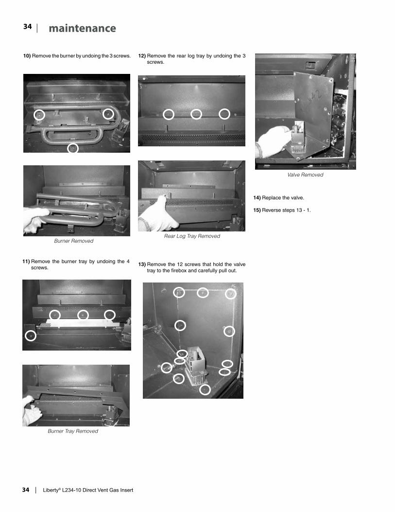
12) Remove the rear log tray by undoing the 3 screws.
Rear Log Tray Removed
13) Remove the 12 screws that hold the valve tray to the firebox and carefully pull out.
14) Replace the valve.
15) Reverse steps 13 - 1.
10) Remove the burner by undoing the 3 screws.
11) Remove the burner tray by undoing the 4 screws.
Burner Removed
Burner Tray Removed
Valve Removed

Liberty® L234-10 Direct Vent Gas Insert | 35
| 35maintenance
GAS MAINTENANCE - RECOMMENDED ANNUAL ROUTINE
Gas Maintenance
09.14.201920-324
Inspect
• Pilotassembly• Burner• Pressurereliefgaskets/doors• Flueconnectorgasketifpresent• Doorseal• Firebox• Venting• Batteries(remotehandheld,remotereceiver,
DCsparker,changeasneeded)• Burnermedia(changeasneeded)• Airshuttersetting• Wiring
Clean
• Glass• Interiorbricks/panels• Burnerports&burnerairshutter• Fanblades• Logset• Pilotorifices• Pilothood(changeasneeded)• Flamesensor(electronicignitionmodels)• Flameelectrode• Burnerorifice• Thermocouple(millivoltmodels)• Thermopile(millivoltmodels)
Recommended Annual Routine Maintenance for Gas Fireplaces, Stoves and Inserts
InorderforyourRegencyappliancetocontinuetoprovidecomforttoyourhomeperiodicmaintenancemustbeperformedtoensureitisoperatingatpeakefficiency.Theitemsinthelistshouldbecheckedbyalicensedgasservicetechnicianduringtheannualservicecheck.Yourunitmayrequiremorefrequentmaintenancechecksifyounoticeanychangesinhowitoperates.Operationalchangestolookforcaninclude,butarenotlimitedto,extendedstartuptime,increasedfannoise,residue/carbonbuildup,whitebuildupontheglass/firebox,increasedoperatingnoiseetc.Shouldanyoftheseorotherconditionsarise,discontinueuseandscheduleaservicecheckwithyourlocallicensedgastechnician.Thelistbelowshowsitemsyourlicensedservicetechnicianwillneedtocheckandserviceatleastannually.
Check
• Voltageonthermocouple/thermopile(mil-livoltmodels)
• Ohmsreadingonflamesense(electronicignitionmodels)
• Inlet/outletfuelpressuresasperratingplate• Voltage/ohmsreadingsongasvalve• Ohmsreadingtoon/offswitchcircuit(Mili-
voltmodels)
Gas Leak Tests
• Checkmaingaslineconnectiontovalve• Checkshutoffvalveconnections• Checkconnectionatgasvalveoutlet• Checkconnectionatmainburnerorifice• Checkpilotfuellineatvalveandatpilotassembly

36 | Liberty® L234-10 Direct Vent Gas Insert
| 36 parts list
MAIN ASSEMBLY
Part # Description
1) 940-355/P Glass
536-539 Door Frame Assembly no Glass
536-540 Door Frame Assembly with Glass
2) 948-463 Burner Assy - NG/LP
3) 536-092 Log Tray Middle
4) 536-014 Log Tray Rear
5) 536-011 Fan Access Plate
6) 536-107 Gasket - Fan Access Plate
7) 536-517/P Fan Assembly 120 V
910-215/P Fan Motor 120 V
910-794 Power Cord
910-985 Wire Harness (Faceplate) - Black
910-986 Wire Harness (Faceplate) - Red
910-692 Wire Fan to Power Cord Ground
910-142 Fan Auto On/Off Thermodisc
536-522 Baffle Plate Assembly
9) 536-901 Brick Panel Set - Standard Brown
9) 536-902 Brick Panel Set - Standard Red
511-031 Brick Clip
12) 537-515 Flue Adaptor Assembly
13) 820-389 Thermodisc Bracket
14) 536-091 Pilot Shield
15) 910-038/P Pilot Assy- 3 Flame - S.I.T. - NG
910-039/P Pilot Assy - 3 Flame - S.I.T. - LP
904-430 Orifice #42 - NG
904-163 Orifice #54 - LP
936-170 Orifice Gasket
Part # Description
16) 537-574/P Valve Assembly - NG
537-576/P Valve Assembly - LP
910-073 Battery Holder - DC Sparker
910-074 DC Sparker - Switch
910-578 Valve - S.I.T. - Natural Gas
910-580 Valve - S.I.T. - Propane
18) 535-001 Safety Screen Frame
18a) 535-000 Safety Screen Mesh
535-002 Safety Screen Insert
911-228/P Remote Receiver
910-592 Remote Transmitter Handheld GTMF
19) 911-127 Remote receiver battery compartment
910-386 Thermocouple
910-341 Thermopile
910-096 Pilot Hood
910-036 Pilot Orifice NG
910-037 Pilot Orifice LP
910-432 Pilot Tube w/nuts
910-581 Stepper Motor NG
910-582 Stepper Motor LP
536-106 Thermal Insulation
536-109 Gasket - Valve Tray
536-930 Complete Log Set
537-969 Conversion Kit LP
537-940 Hearth Trim
919-442 Manual
* Not available as a replacement part.

Liberty® L234-10 Direct Vent Gas Insert | 37
| 37warranty
MAIN ASSEMBLY
a

38 | Liberty® L234-10 Direct Vent Gas Insert
| 38 parts list
537-924 Low Profile Faceplate

Liberty® L234-10 Direct Vent Gas Insert | 39
| 39notes

40 | Liberty® L234-10 Direct Vent Gas Insert
| 40 warranty
Revision Date: February 2019 Regency Gas Products Warranty
Limited Lifetime Warranty FPI Fireplace Products International Ltd. (for Canadian customers) and Fireplace Products U.S., Inc. (for U.S. customers) (collectively referred to herein as “FPI”) extends this Limited Lifetime Warranty to the original purchaser of this appliance provided the product remains in the original place of installation. The items covered by this limited warranty and the period of such coverage is set forth in the table below. Some conditions apply (see below). The policy is not transferable, amendable or negotiable under any circumstances.
Indoor Gas Products Part Supplier Labor
Coverage Warranty Coverage Parts and Labor Lifetime 5 years 2 years 1 year Warranty (Years)
Firebox and Heat Exchanger 3 Steel Burner Tube 3 Glass Thermal breakage only 3 All Surrounds/Inlays Finishes 3 Brick Panels/Log sets/Ceramic Burners 3
All Castings 3 Valve assembly and all gas control components, (Pilot assembly, flame sensors, Spark Electrode, Pilot Tubing, Orifices, Thermocouple, Thermopile)
2
All Other Electrical components,(Ignition Control Boards, Wiring, Switches, Blowers, Blower Control Module, Battery Pack, Remote Control Systems)
2
Enamel Panels 1 Venting/Venting Components 1 All Stainless steel surrounds 1 All Firebox Media (Crystals, Firebeads, Volcanic, Ceramic & Spa Stones)
1
All hardware 1 Mesh/Glass Safety Barriers 1 Accent Light Bulbs 1 Glass (Crazing) 1
Conditions: Warranty protects against defect in manufacture or FPI factory assembled components only, unless herein specified otherwise. Any part(s) found to be defective during the warranty period as outlined above will be repaired or replaced at FPI’s option through an accredited distributor, dealer or pre-approved and assigned agent provided that the defective part is returned to the distributor, dealer or agent for inspection if requested by FPI. Alternatively, FPI may at its own discretion fully discharge all of its obligations under the warranty by refunding the verified purchase price of the product to the original purchaser. The purchase price must be confirmed by the original Bill of Sale. The authorized selling dealer, or an alternative authorized FPI dealer if pre-approved by FPI, is responsible for all in-field diagnosis and service work related to all warranty claims. FPI is not responsible for results or costs of workmanship of unauthorized FPI dealers or agents in the negligence of their service work.

Liberty® L234-10 Direct Vent Gas Insert | 41
| 41warranty
Revision Date: February 2019 Regency Gas Products Warranty
At all times FPI reserves the right to inspect reported complaints on location in the field claimed to be defective prior to processing or authorizing of any claim. Failure to allow this upon request will void the warranty. All warranty claims must be submitted by the dealer servicing the claim, including a copy of the Bill of Sale (proof of purchase by you). All claims must be complete and provide full details as requested by FPI to receive consideration for evaluation. Incomplete claims may be rejected. Unit must be installed according to all manufacturers’ instructions as per the manual. All Local and National required codes must be met. The installer is responsible to ensure the unit is operating as designed at the time of installation. The original purchaser is responsible for annual maintenance of the unit, as outlined in the owner’s manual. As outlined below, the warranty may be voided due to problems caused by lack of maintenance. Repair/replacement parts purchased by the consumer from FPI after the original coverage has expired on the unit will carry a 90 day warranty, valid with a receipt only. Any item shown to be defective will be repaired or replaced at our discretion. No labor coverage is included with these parts Exclusions: This Limited Lifetime Warranty does not extend to paint, rust or corrosion of any kind due to a lack of maintenance or improper venting, combustion air provision, corrosive chemicals (i.e. chlorine, salt, air, etc.), door or glass gasketing. Malfunction, damage or performance based issues as a result of environmental conditions, location, chemical damages, downdrafts, installation error, installation by an unqualified installer, incorrect chimney components (including but not limited to cap size or type), operator error, abuse, misuse, use of improper fuels , lack of regular maintenance and upkeep, acts of God, weather related problems from hurricanes, tornados, earthquakes, floods, lightning strikes/bolts or acts of terrorism or war, which result in malfunction of the appliance are not covered under the terms of this Limited Lifetime Warranty. FPI has no obligation to enhance or modify any unit once manufactured (i.e. as products evolve, field modifications or upgrades will not be performed on existing appliances). This warranty does not cover dealer travel costs for diagnostic or service work. All labor rates paid to authorized dealers are subsidized, pre-determined rates. Dealers may charge homeowner for travel and additional time beyond their subsidy. Any unit showing signs of neglect or misuse will not be covered under the terms of this warranty policy and may void this warranty. This includes units with rusted or corroded fireboxes which have not been reported as rusted or corroded within three (3) months of installation/purchase. Units which show evidence of being operated while damaged, or with problems known to the purchaser and causing further damages will void this warranty. Units where the serial no. has been altered, deleted, removed or made illegible will void this warranty. Minor movement, expansion and contraction of the steel is normal and is not covered under the terms of this warranty. FPI is not liable for the removal or replacement of facings or finishing in order to repair or replace any appliance in the field. Freight damages for products or parts are not covered under the terms of the warranty. Products made or provided by other manufacturers and used in conjunction with the FPI appliance without prior authorization from FPI may void this warranty.

42 | Liberty® L234-10 Direct Vent Gas Insert
| 42 warranty
Revision Date: February 2019 Regency Gas Products Warranty
Limitations of Liability: The original purchaser’s exclusive remedy under this warranty, and FPI’s sole obligation under this warranty, express or implied, in contract or in tort, shall be limited to replacement, repair, or refund, as outlined above. IN NO EVENT WILL FPI BE LIABLE UNDER THIS WARRANTY FOR ANY INCIDENTAL OR CONSEQUENTIAL COMMERCIAL DAMAGES OR DAMAGES TO PROPERTY. TO THE EXTENT PERMITTED BY APPLICABLE LAW, FPI MAKES NO EXPRESS WARRANTIES OTHER THAN THE WARRANTY SPECIFIED HEREIN. THE DURATION OF ANY IMPLIED WARRANTY IS LIMITED TO DURATION OF THE EXPRESSED WARRANTY SPECIFIED ABOVE. IF IMPLIED WARRANTIES CANNOT BE DISCLAIMED, THEN SUCH WARRANTIES ARE LIMITED IN DURATION TO THE DURATION OF THIS WARRANTY. Some U.S. states do not allow limitations on how long an implied warranty lasts, or allow exclusion or limitation of incidental or consequential damages, so the above limitations or exclusions may not apply to you. Customers located outside the U.S. should consult their local, provincial or national legal codes for additional terms which may be applicable to this warranty. How to Obtain Warranty Service: Customers should contact the authorized selling dealer to obtain warranty service. In the event the authorized selling dealer is unable to provide warranty service, please contact FPI by mail at the address listed below. Please include a brief description of the problem and your address, email and telephone contact information. A representative will contact you to make arrangements for an inspection and/or warranty service. Canadian Warrantor: FPI Fireplace Products International Ltd. 6988 Venture St. Delta, British Columbia Canada, V4G 1H4
U.S. Warrantor: Fireplace Products U.S., Inc. PO Box 2189 PMB 125 Blaine, WA United States, 98231
Or contact the Regency Customer Care Centre at 1-800-442-7432 (phone) / 604-946-4349 (fax) Product Registration and Customer Support: Thank you for choosing a Regency Fireplace. Regency strives to be a world leader in the design, manufacture, and marketing of hearth products. To provide the best support for your product, we request that you complete a product registration form at http://www.regency-fire.com/Customer-Care/Warranty-Registration.aspx within ninety (90) days of purchase.

Liberty® L234-10 Direct Vent Gas Insert | 43
| 43warranty
Product Registration and Customer Support:
Thank you for choosing a Regency Fireplace. Regency strives to be a world leader in the design, manufacture, and marketing of hearth products. To provide the best support for your product, we request that you complete a product registration form found on our Web Site under Customer Care within ninety (90) days of purchase.
For purchases made in CANADA or the UNITED STATES: http://www.regency-fire.com/Customer-Care/Warranty-Registration.aspx
For purchases made in AUSTRALIA: http://www.regency-fire.com.au/Customer-Care/Warranty-Registration.aspx
You may also complete the warranty registration form below to register your Regency Fireplace Product and mail and/or fax it back to us, and we will register the warranty for you. It is important you provide us with all the information below in order for us to serve you better.
Warranty Registration Form (or Register online immediately at the above Web Site):
Warranty Details
Serial Number (required):
Purchase Date (required) (mm/dd/yyyy):
Product Details
Product Model (required):
Dealer Details
Dealer Name (required):
Dealer Address:
Dealer Phone #:
Installer:
Date Installed (mm/dd/yyyy):
Your Contact Details (required)
Name:
Address:
Phone:
Email:
For purchases made in CANADA:
FPI Fireplace Products International Ltd. 6988 Venture St. Delta, British Columbia Canada, V4G 1H4
Phone: 604-946-5155 Fax: 1-866-393-2806
For purchases made in the UNITED STATES:
Fireplace Products US, Inc. PO Box 2189 PMB 125 Blaine, WA United States, 98231
Phone: 604-946-5155 Fax: 1-866-393-2806
For purchases made in AUSTRALIA:
Fireplace Products Australia Pty Ltd 1- 3 Conquest WayHallam, VICAustralia, 3803
Phone: +61 3 9799 7277 Fax: +61 3 9799 7822
For fireplace care and tips and answers to most common questions please visit our Customer Care section on our Web Site. Please feel free to contact your selling dealer if you have any questions about your Regency product.

44 | Liberty® L234-10 Direct Vent Gas Insert
| 44 warranty

Liberty® L234-10 Direct Vent Gas Insert | 45
| 45notes

46 | Liberty® L234-10 Direct Vent Gas Insert
| 46 notes


Printed in CanadaRegency and Liberty are trademarks of Regency Fireplace Products International Ltd. © Copyright 2020, Regency Fireplace Products International Ltd. All rights reserved.
Installer: Please complete the following information
Dealer Name & Address: ______________________________________________
___________________________________________________________________
Installer: ___________________________________________________________
Phone #: ___________________________________________________________
Date Installed: ______________________________________________________
Serial #: ____________________________________________________________
Liberty L234 Product Video