Embed Size (px)
Citation preview
Category: 5 SERVICE INFORMATION LETTER (SIL)
LIBERTY AEROSPACE, INC. SERVICE DOCUMENT Contains Useful Information Pertaining To Your Aircraft SIL-06-006
Technical Portions FAA Approved
SUBJECT TCM EDI-200 LIGHT WEIGHT FADEC DATA RECORDER INSTALLATION.
ISSUE REVISION
REASON FOR ACTION Upgrade PURPOSE TCM EDI-200 Light Weight FADEC Data Recorder Installation. COMPLIANCE For information only. MODELS AFFECTED All Liberty XL-2 Aircraft SN 0001 & up. PURPOSE:
This procedure installs a Teledyne Continental Motors Engine Data Interface model 200 (EDI-200) on a Liberty Aerospace model XL2 aircraft.
Figure 1 - EDI-200 Assembly
INSTALLATION AND TEST PROCEDURE:
1.1 Instrument Console Assembly Preparation
1.1.1 Objective:
This section prepares the aircraft instrument console to receive the EDI-200 mounting bracket hardware.
1.1.2 Parts Required:
Page No.
REV. Month
12
Day
05
Year
06
Month Day Year
1 Air Cargo Way
Melbourne, FL, 32901 Phone: 321-752-0332
1
Part Number Part Description Supplier Qty CCR244CS-3-02 Rivet, Blind, Nut Plate, 100° Liberty 8 Flush Head 286 CRES MS21059-06 Nut, Self Locking, Plate, Two Lug, Floating #6-32 Liberty 4
1.1.3 Place the master switch in the OFF position
1.1.4 Place the FADEC B switch (SW005) in the OFF position.
1.1.5 Locate on the circuit breaker panel CB 001, 70A, BATT and pull to the open position
1.1.6 Open and remove circuit breaker panel assembly 135A-80-110 to gain clear access to the instrument panel console floor.
NOTE: The CB panel will remain out of the aircraft until a later step in the EDI-200 installation process.
Category: 5 SERVICE INFORMATION LETTER (SIL)
LIBERTY AEROSPACE, INC. SERVICE DOCUMENT Contains Useful Information Pertaining To Your Aircraft SIL-06-006
Technical Portions FAA Approved
SUBJECT TCM EDI-200 LIGHT WEIGHT FADEC DATA RECORDER INSTALLATION.
ISSUE REVISION
CAUTION:
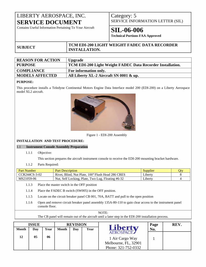
Do not attempt drilling of EDI-200 mounting bracket holes with the CB panel in place. Wire damage may result.
1.1.7 Prepare EDI-200 mounting bracket hardware holes in the instrument console as shown in Figure 2.
Figure 2 - EDI-200 Mounting Bracket Hardware Holes
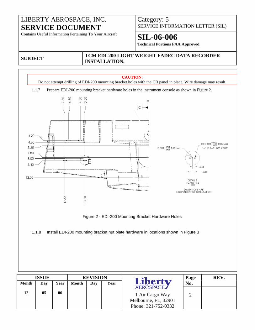
1.1.8 Install EDI-200 mounting bracket nut plate hardware in locations shown in Figure 3
Page No.
REV. Month
12
Day
05
Year
06
Month Day Year
1 Air Cargo Way
Melbourne, FL, 32901 Phone: 321-752-0332
2
Category: 5 SERVICE INFORMATION LETTER (SIL)
LIBERTY AEROSPACE, INC. SERVICE DOCUMENT Contains Useful Information Pertaining To Your Aircraft SIL-06-006
Technical Portions FAA Approved
SUBJECT TCM EDI-200 LIGHT WEIGHT FADEC DATA RECORDER INSTALLATION.
ISSUE REVISION
Figure 3 - EDI-200 Mounting Bracket Nut Plate Installation
1.1.9 Instrument console assembly preparation complete
Page No.
REV. Month
12
Day
05
Year
06
Month Day Year
1 Air Cargo Way
Melbourne, FL, 32901 Phone: 321-752-0332
3
Category: 5 SERVICE INFORMATION LETTER (SIL)
LIBERTY AEROSPACE, INC. SERVICE DOCUMENT Contains Useful Information Pertaining To Your Aircraft SIL-06-006
Technical Portions FAA Approved
SUBJECT TCM EDI-200 LIGHT WEIGHT FADEC DATA RECORDER INSTALLATION.
ISSUE REVISION
1.2 EDI-200 Installation
1.2.1 Objective:
This section installs the EDI-200 unit, bracket and wire harness in the aircraft.
1.2.2 Parts Required
Page No.
REV. Month
12
Day
05
Year
06
Month Day Year
1 Air Cargo Way
Melbourne, FL, 32901 Phone: 321-752-0332
4
Part Number Part Description Supplier Qty 135A-80-173 EDI Bracket Assembly Liberty 1 135A-81-346 EDI Cable Liberty 1 14049 EDI-200 (TCM PN 657230) Aerosance 1 MS51957-30 6-32 x0.500 Pan Head Screw Corrosion Resistant Liberty 8 NAS1149N632R Flat Washer #6.149 ID x 0.375 OD x 0.32 TH Liberty 4 MS3367-5-0 CABLE TIE, BLACK Liberty 6
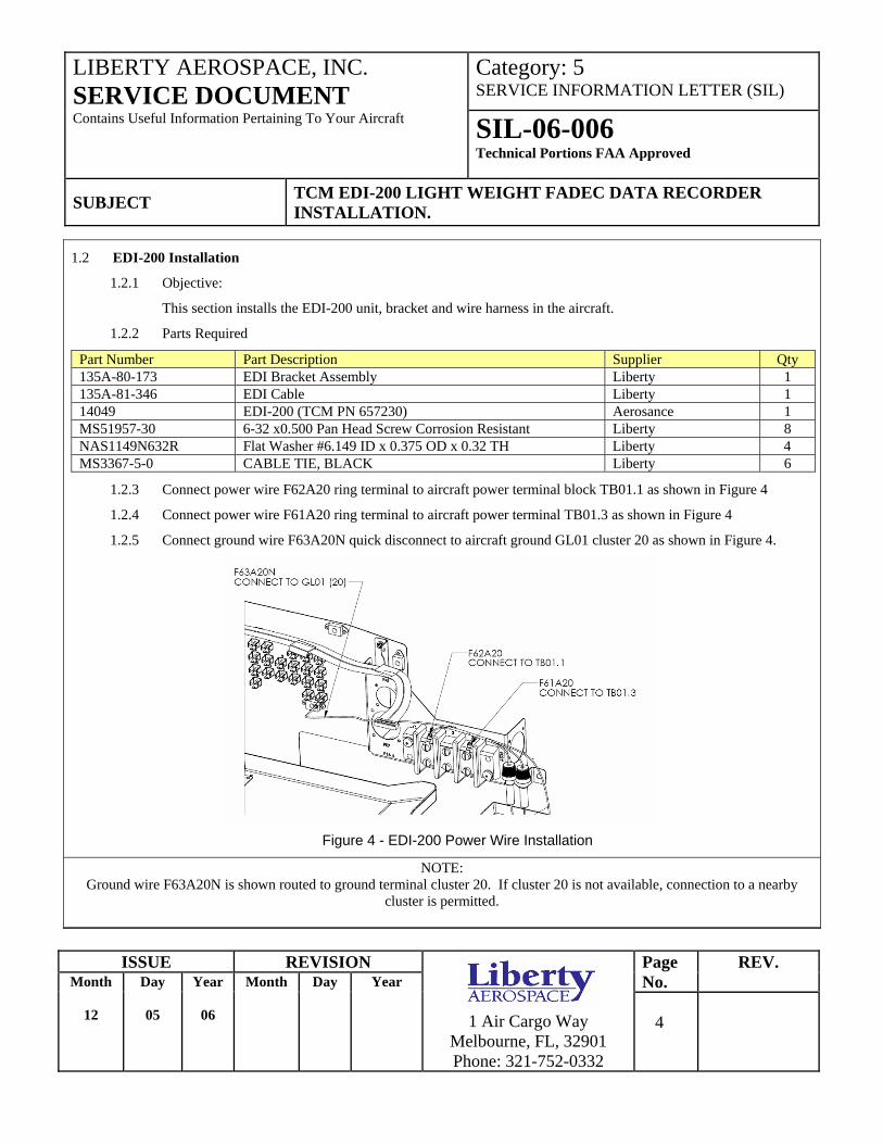
1.2.3 Connect power wire F62A20 ring terminal to aircraft power terminal block TB01.1 as shown in Figure 4
1.2.4 Connect power wire F61A20 ring terminal to aircraft power terminal TB01.3 as shown in Figure 4
1.2.5 Connect ground wire F63A20N quick disconnect to aircraft ground GL01 cluster 20 as shown in Figure 4.
Figure 4 - EDI-200 Power Wire Installation
NOTE: Ground wire F63A20N is shown routed to ground terminal cluster 20. If cluster 20 is not available, connection to a nearby
cluster is permitted.
Category: 5 SERVICE INFORMATION LETTER (SIL)
LIBERTY AEROSPACE, INC. SERVICE DOCUMENT Contains Useful Information Pertaining To Your Aircraft SIL-06-006
Technical Portions FAA Approved
SUBJECT TCM EDI-200 LIGHT WEIGHT FADEC DATA RECORDER INSTALLATION.
ISSUE REVISION
1.2.6 Record EDI-200 data plate information below for later aircraft log book entry:
NAME DATA
Model Name
Part Number
Serial Number
Software
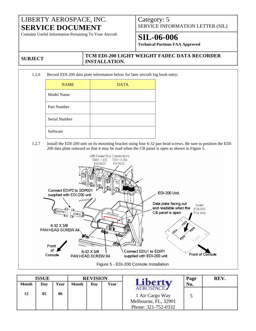
1.2.7 Install the EDI-200 unit on its mounting bracket using four 6-32 pan head screws. Be sure to position the EDI-200 data plate outward so that it may be read when the CB panel is open as shown in Figure 5.
Figure 5 - EDI-200 Console Installation
Page No.
REV. Month
12
Day
05
Year
06
Month Day Year
1 Air Cargo Way
Melbourne, FL, 32901 Phone: 321-752-0332
5
Category: 5 SERVICE INFORMATION LETTER (SIL)
LIBERTY AEROSPACE, INC. SERVICE DOCUMENT Contains Useful Information Pertaining To Your Aircraft SIL-06-006
Technical Portions FAA Approved
SUBJECT TCM EDI-200 LIGHT WEIGHT FADEC DATA RECORDER INSTALLATION.
ISSUE REVISION Page No.
REV. Month
12
Day
05
Year
06
Month Day Year
1 Air Cargo Way
Melbourne, FL, 32901 Phone: 321-752-0332
6
1.2.8 Feed the EDI-200, lead wire and bracket assembly up through the instrument panel console into location and
secure with 6-32 x 3/8 pan head screws and washers as indicated in Figure 5.
1.2.9 Locate and connect EDIJ1 to EDIP1 as shown in figure 5 securing the connection by tightening connector locking screws (2).
1.2.10 Secure power wires, EDIJ1 and EDIP1 with wire ties to adjacent console wire harnesses routed as shown in Figure 5.
1.2.11 Verify all EDI wires are clear of adjacent structure and will not interfere with CB Panel installation to follow.
1.2.12 Position circuit breaker panel 135A-80-110 in front of the instrument console permitting access to connector SDP001.
1.2.13 Referring to Figure 5, connect EDI wire harness connector EDIP2 to SDP001 securing the connection by tightening connector locking screws (2).
1.2.14 Route and secure EDIP2 and SDP001 with wire ties to adjacent console wire harnesses routing clear of the CB panel installation to follow.
1.2.15 Complete installation of circuit breaker panel 135A-80-110.
CAUTION: When installing the circuit breaker panel care must be taken to assure wire harnesses are free and clear of all near by structures
within the console. Do not force the circuit panel into position. If the panel will not easily fit into position check for wire harness interference.
1.2.16 EDI-200 installation complete.
Category: 5 SERVICE INFORMATION LETTER (SIL)
LIBERTY AEROSPACE, INC. SERVICE DOCUMENT Contains Useful Information Pertaining To Your Aircraft SIL-06-006
Technical Portions FAA Approved
SUBJECT TCM EDI-200 LIGHT WEIGHT FADEC DATA RECORDER INSTALLATION.
ISSUE REVISION
2 EDI-200 SETUP AND TEST
2.1 Flash Card Memory Installation
2.1.1 Objective:
The EDI-200 stores data for flight time in proportion to the size of a compact flash memory card inserted. For example a 128 MB card stores in excess of 150 hours of data. With a 1GB CF card storage will exceed 1,500 hours. This section will install a 1Gb card in preparation for functional testing.
2.1.2 Parts Required:
Page No.
REV. Month
12
Day
05
Year
06
Month Day Year
1 Air Cargo Way
Melbourne, FL, 32901 Phone: 321-752-0332
7
TCM Part Number Part Description Supplier Qty 656993-1 Memory Card TCM 1
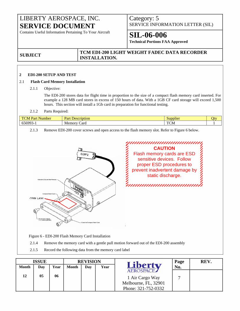
2.1.3 Remove EDI-200 cover screws and open access to the flash memory slot. Refer to Figure 6 below.
Figure 6 - EDI-200 Flash Memory Card Installation
2.1.4 Remove the memory card with a gentle pull motion forward out of the EDI-200 assembly
2.1.5 Record the following data from the memory card label
CAUTION Flash memory cards are ESD
sensitive devices. Follow proper ESD procedures to
prevent inadvertent damage by static discharge.
Category: 5 SERVICE INFORMATION LETTER (SIL)
LIBERTY AEROSPACE, INC. SERVICE DOCUMENT Contains Useful Information Pertaining To Your Aircraft SIL-06-006
Technical Portions FAA Approved
SUBJECT TCM EDI-200 LIGHT WEIGHT FADEC DATA RECORDER INSTALLATION.
ISSUE REVISION Page No.
REV. Month
12
Day
05
Year
06
Month Day Year
1 Air Cargo Way
Melbourne, FL, 32901 Phone: 321-752-0332
8
NAME VALUE
AEROSANCE PART NUMBER
TCM PART NUMBER
DATE CODE
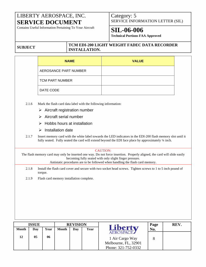
2.1.6 Mark the flash card data label with the following information:
Aircraft registration number Aircraft serial number Hobbs hours at installation Installation date
2.1.7 Insert memory card with the white label towards the LED indicators in the EDI-200 flash memory slot until it fully seated. Fully seated the card will extend beyond the EDI face place by approximately ¼ inch.
CAUTION:
The flash memory card may only be inserted one way. Do not force insertion. Properly aligned, the card will slide easily becoming fully seated with only slight finger pressure.
Antistatic procedures are to be followed when handling the flash card memory.
2.1.8 Install the flash card cover and secure with two socket head screws. Tighten screws to 1 to 5 inch pound of torque.
2.1.9 Flash card memory installation complete.
Category: 5 SERVICE INFORMATION LETTER (SIL)
LIBERTY AEROSPACE, INC. SERVICE DOCUMENT Contains Useful Information Pertaining To Your Aircraft SIL-06-006
Technical Portions FAA Approved
SUBJECT TCM EDI-200 LIGHT WEIGHT FADEC DATA RECORDER INSTALLATION.
ISSUE REVISION Page No.
REV. Month
12
Day
05
Year
06
Month Day Year
1 Air Cargo Way
Melbourne, FL, 32901 Phone: 321-752-0332
9
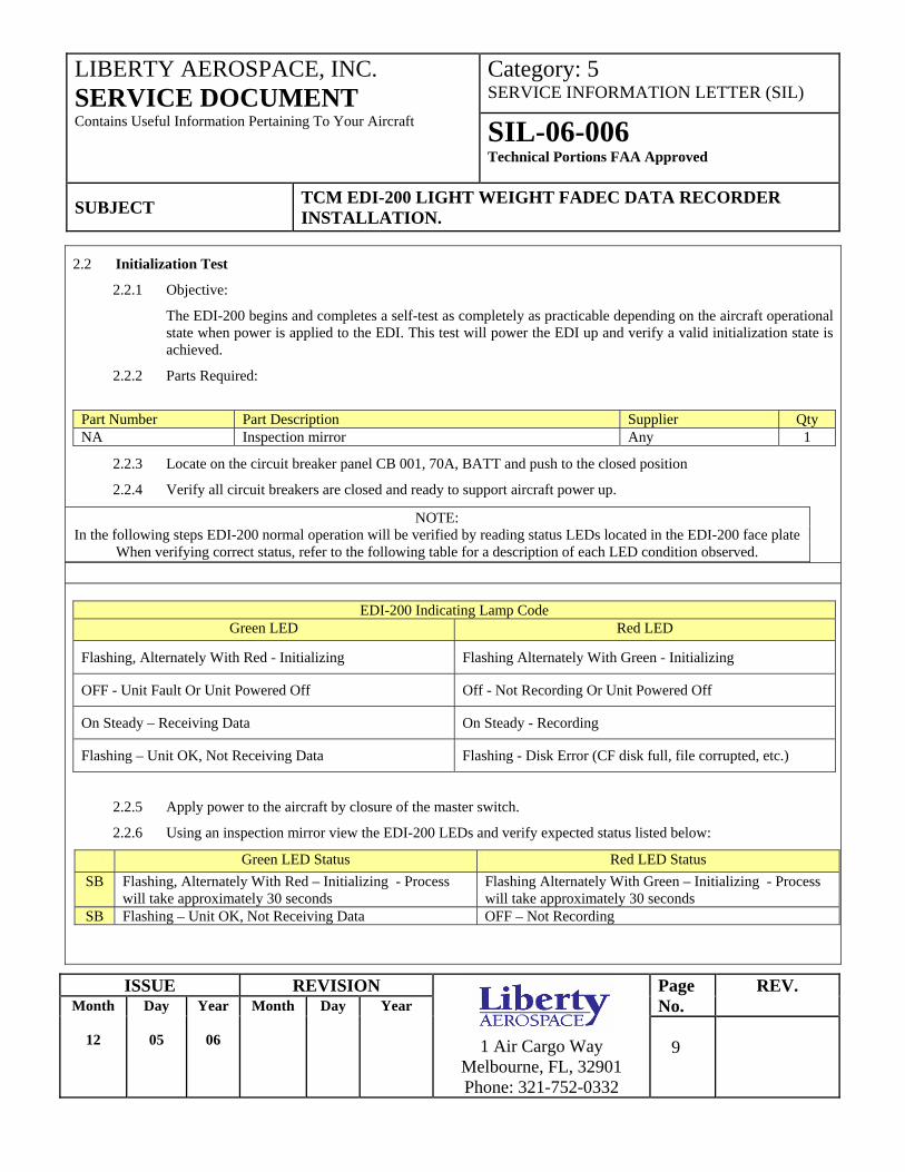
2.2 Initialization Test
2.2.1 Objective:
The EDI-200 begins and completes a self-test as completely as practicable depending on the aircraft operational state when power is applied to the EDI. This test will power the EDI up and verify a valid initialization state is achieved.
2.2.2 Parts Required:
Part Number Part Description Supplier Qty NA Inspection mirror Any 1
2.2.3 Locate on the circuit breaker panel CB 001, 70A, BATT and push to the closed position
2.2.4 Verify all circuit breakers are closed and ready to support aircraft power up.
NOTE: In the following steps EDI-200 normal operation will be verified by reading status LEDs located in the EDI-200 face plate
When verifying correct status, refer to the following table for a description of each LED condition observed.
EDI-200 Indicating Lamp Code
Green LED Red LED
Flashing, Alternately With Red - Initializing Flashing Alternately With Green - Initializing
OFF - Unit Fault Or Unit Powered Off Off - Not Recording Or Unit Powered Off
On Steady – Receiving Data On Steady - Recording
Flashing – Unit OK, Not Receiving Data Flashing - Disk Error (CF disk full, file corrupted, etc.)
2.2.5 Apply power to the aircraft by closure of the master switch.
2.2.6 Using an inspection mirror view the EDI-200 LEDs and verify expected status listed below:
Green LED Status Red LED Status SB Flashing, Alternately With Red – Initializing - Process
will take approximately 30 seconds Flashing Alternately With Green – Initializing - Process will take approximately 30 seconds
SB Flashing – Unit OK, Not Receiving Data OFF – Not Recording

Category: 5 SERVICE INFORMATION LETTER (SIL)
LIBERTY AEROSPACE, INC. SERVICE DOCUMENT Contains Useful Information Pertaining To Your Aircraft SIL-06-006
Technical Portions FAA Approved
SUBJECT TCM EDI-200 LIGHT WEIGHT FADEC DATA RECORDER INSTALLATION.
ISSUE REVISION Page No.
REV. Month
12
Day
05
Year
06
Month Day Year
1 Air Cargo Way
Melbourne, FL, 32901 Phone: 321-752-0332
10
verify expected status listed below:
Green LED Status Red LED Status SB On Steady – Receiving Data Off - Not Recording
2.2.8 Power up FADEC B by closing FADEC PWR switch B. Using an inspection mirror view the EDI LEDs and verify expected status listed below:
Green LED Status Red LED Status SB On Steady – Receiving Data Off - Not Recording
2.2.9 Place FADEC PWR A and FADEC PWR B switches in the OFF state. Using and inspection mirror view the EDI LEDs and verify expected status listed below
Green LED Status Red LED Status SB Flashing – Unit OK, Not Receiving Data Off - Not Recording
2.2.10 Remove power from the aircraft by deactivation of the master switch. Using an inspection mirror, view the EDI LEDs and verify expected status listed below:
Green LED Status Red LED Status SB OFF - Unit Fault Or Unit Powered Off Off - Not Recording Or Unit Powered Off
2.2.11 EDI-200 Initialization Test Complete
2.3 Engine Data Recording Indication Test
2.3.1 Objective:
Once the EDI-200 has initialized it is ready to start recording engine data. EDI-200 recording will not begin until the engine speed is 300 RPM or greater. This test will verify the EDI-200 does indicate recording of data with the engine running.
2.3.2 Parts Required:
Part Number Part Description Supplier Qty NA Inspection mirror Any 1
2.3.3 Perform a normal start of the engine and set the throttle to idle (850 to 950 RPM)
2.3.4 Using an inspection mirror, observe the EDI-200 LEDs and verify expected status listed below:
Green LED Status Red LED Status SB On Steady – Receiving Data On Steady - Recording
2.3.5 Perform an engine shutdown leaving power applied through the master switch, FADEC PWR A and FADEC PWR B Switches.
Category: 5 SERVICE INFORMATION LETTER (SIL)
LIBERTY AEROSPACE, INC. SERVICE DOCUMENT Contains Useful Information Pertaining To Your Aircraft SIL-06-006
Technical Portions FAA Approved
SUBJECT TCM EDI-200 LIGHT WEIGHT FADEC DATA RECORDER INSTALLATION.
ISSUE REVISION Page No.
REV. Month
12
Day
05
Year
06
Month Day Year
1 Air Cargo Way
Melbourne, FL, 32901 Phone: 321-752-0332
11
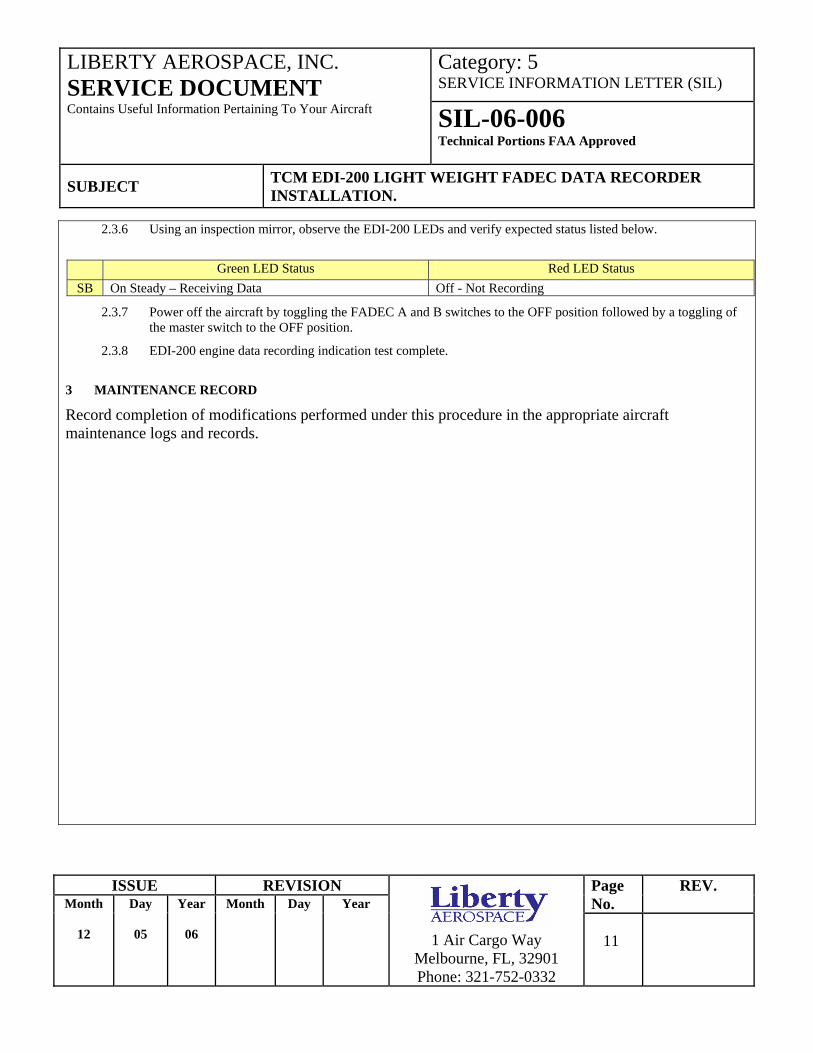
2.3.6 Using an inspection mirror, observe the EDI-200 LEDs and verify expected status listed below.
Green LED Status Red LED Status
SB On Steady – Receiving Data Off - Not Recording
2.3.7 Power off the aircraft by toggling the FADEC A and B switches to the OFF position followed by a toggling of the master switch to the OFF position.
2.3.8 EDI-200 engine data recording indication test complete.
3 MAINTENANCE RECORD
Record completion of modifications performed under this procedure in the appropriate aircraft maintenance logs and records.
Category: 5 SERVICE INFORMATION LETTER (SIL)
LIBERTY AEROSPACE, INC. SERVICE DOCUMENT Contains Useful Information Pertaining To Your Aircraft SIL-06-006
Technical Portions FAA Approved
SUBJECT TCM EDI-200 LIGHT WEIGHT FADEC DATA RECORDER INSTALLATION.
ISSUE REVISION Page No.
REV. Month
12
Day
05
Year
06
Month Day Year
1 Air Cargo Way
Melbourne, FL, 32901 Phone: 321-752-0332
12
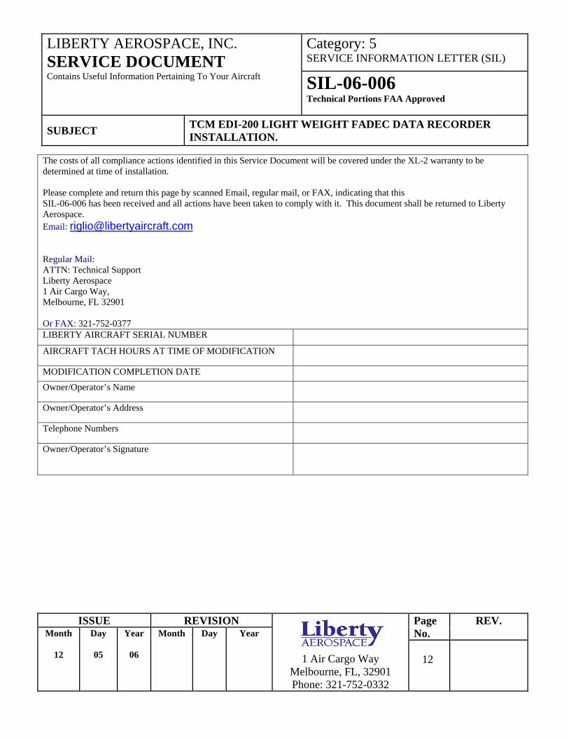
The costs of all compliance actions identified in this Service Document will be covered under the XL-2 warranty to be determined at time of installation. Please complete and return this page by scanned Email, regular mail, or FAX, indicating that this SIL-06-006 has been received and all actions have been taken to comply with it. This document shall be returned to Liberty Aerospace. Email: [email protected] Regular Mail: ATTN: Technical Support Liberty Aerospace 1 Air Cargo Way, Melbourne, FL 32901 Or FAX: 321-752-0377 LIBERTY AIRCRAFT SERIAL NUMBER
AIRCRAFT TACH HOURS AT TIME OF MODIFICATION
MODIFICATION COMPLETION DATE
Owner/Operator’s Name
Owner/Operator’s Address
Telephone Numbers
Owner/Operator’s Signature