Embed Size (px)
Citation preview
LIBERIA
CIVIL AVIATION REGULATIONS
PART 23.1
AIR NAVIGATION SERVICE
EDITION 1.0
APRIL 2016

PART 23.1: RADIO NAVIGATION AID
September 2019 Edition 3.0 Page 2 of 24
LIBERIA CIVIL AVIATION REGULATIONS
AUTHORITY TO PROMULGATE
CIVIL AVIATION REGULATIONS
IN EXERCISE OF THE POWERS CONFERRED ON THE DIRECTOR GENERAL OF
LIBERIA CIVIL AVIATION AUTHORITY UNDER THE LIBERIA CIVIL AVIATION ACT OF 2005 THESE REGULATIONS ARE MADE.
THESE REGULATIONS AS AMENDED SUPERSEDE LIBERIA CIVIL AVIATION REGULATIONS OF 2010.
DATE:______________
SIGNATURE: ___________________
DIRECTOR GENERAL

PART 23.1: RADIO NAVIGATION AID
September 2019 Edition 3.0 Page 3 of 24
LIBERIA CIVIL AVIATION REGULATIONS
THIS PAGE INTENTIONALLY LEFT BLANK

PART 23.1: RADIO NAVIGATION AID
September 2019 Edition 3.0 Page 4 of 24
LIBERIA CIVIL AVIATION REGULATIONS
DISTRIBUTION LIST
PERSON/INSTITUTION NUMBER OF COPY
1. Director General (DG) 1
2. Flight Safety Standards Department(FSSD) 1
3. Communication, Navigation & Surveillance(CNS) 1
4. Planning, Economic & Statistics(PES) 1
5. Administration (Adm.) 2
6. Air Traffic Management(ATM) 1
7. Aeronautical Information Management(AIM) 1
8. ATM- Inspector 1
9. LCAA Library 1
1O. AVSEC Department 1

PART 23.1: RADIO NAVIGATION AID
September 2019 Edition 3.0 Page 5 of 24
LIBERIA CIVIL AVIATION REGULATIONS
THIS PAGE INTENTIONALLY LEFT BLANK

PART 23.1: RADIO NAVIGATION AID
September 2019 Edition 3.0 Page 6 of 24
LIBERIA CIVIL AVIATION REGULATIONS
AMENDMENTS
LOCATION DATE DESCRIPTION

PART 23.1: RADIO NAVIGATION AID
September 2019 Edition 3.0 Page 7 of 24
LIBERIA CIVIL AVIATION REGULATIONS
THIS PAGE INTENTIONALLY LEFT BLANK

PART 23.1: RADIO NAVIGATION AID
September 2019 Edition 3.0 Page 8 of 24
LIBERIA CIVIL AVIATION REGULATIONS
INTRODUCTION
The following Regulations governing Air Navigation Services (ANS) are based on subchapter IV
section 401 of the Liberia Civil Aviation Act of 2006 and in accordance with the following ICAO
Annexes: 3, 4, 10, 11, 12, 15 and related ICAO Documents.
The promulgation of this regulation is based on the authority granted in Section 409 of the Civil
Aviation Act, and is issued under the authority of the Director General, Liberia Civil Aviation Authority
(LCAA), as a duly delegated representative of the LCAA Board of Directors.
The Liberia Civil Aviation Authority is responsible for the preparation and distribution of all
regulations and procedures in sufficient quantities so that all service providers and aircraft operators based in Liberia are able to obtain an authentic copy prior to the effective date of the Regulation.
Subpart 1 of this Regulation is a technical document which defines for international aircraft
operations and systems necessary to provide radio navigation aids used by aircraft in all phases of flight. The requirements and guidance material of this Subpart list essential parameter
specifications for radio navigation aids such as the Global Navigation Satellite System (GNSS), Instrument Landing System (ILS), Microwave Landing System (MLS), Very High Frequency (VHF) Omni-Directional Radio Range (VOR), Non-Directional Radio Beacon (NDB) and Distance Measuring
Equipment (DME).
The information contained in Subpart 1 includes aspects of power requirements, frequency, modulation, signal characteristics and monitoring needed to ensure that suitably equipped aircraft
will be able to receive navigation signals in all parts of the world with the requisite degree of reliability.

PART 23.1: RADIO NAVIGATION AID
September 2019 Edition 3.0 Page 9 of 24
LIBERIA CIVIL AVIATION REGULATIONS
THIS PAGE INTENTIONALLY LEFT BLANK

PART 23.1: RADIO NAVIGATION AID
September 2019 Edition 3.0 Page 10 of 24
LIBERIA CIVIL AVIATION REGULATIONS
Table of Contents
PART 23.1 —RADIO NAVIGATION AIDS ............................................................................................ 12
23.1.1 DEFINITIONS .......................................................................................................................... 12 23.1.2 GENERAL PROVISIONS FOR RADIO NAVIGATION AIDS ................................ 15
Standard radio navigation aids ............................................................................... 15 GROUND AND FLIGHT TESTING ........................................................................... 16 PROVISION OF INFORMATION ON THE OPERATIONAL
STATUS OF RADIO NAVIGATION AIDS ..................................................................... 16 POWER SUPPLY FOR RADIO NAVIGATION AIDS AND
COMMUNICATION SYSTEMS ......................................................................................... 17 HUMAN FACTORS CONSIDERATIONS ............................................................... 17
23.1.3 SPECIFICATIONS FOR RADIO NAVIGATION AIDS ............................................. 17
SPECIFICATION FOR ILS ........................................................................................... 17 SPECIFICATION FOR PRECISION APPROACH RADAR
SYSTEM ..................................................................................................................................... 39 SPECIFICATION FOR VHF OMNIDIRECTIONAL RADIO
RANGE (VOR) .......................................................................................................................... 41 SPECIFICATION FOR NON-DIRECTIONAL RADIO BEACON
(NDB) ........................................................................................................................................... 45 SPECIFICATION FOR UHF DISTANCE MEASURING
EQUIPMENT (DME) .............................................................................................................. 47 SPECIFICATION FOR EN-ROUTE VHF MARKER BEACONS
(75MHZ) ..................................................................................................................................... 67 REQUIREMENTS FOR THE GLOBAL NAVIGATION
SATELLITE SYSTEM (GNSS) ........................................................................................... 68 RESERVED ........................................................................................................................ 80 SYSTEM CHARACTERISTICS OF AIRBORNE ADF
RECEIVING .............................................................................................................................. 80 RESERVED ........................................................................................................................ 81 MICROWAVE LANDING SYSTEM (MLS) CHARACTERISTICS ................. 81
PART 23.1– IMPLEMENTING STANDARDS ................................................................................ 118
IS: 23.1.3.7. TECHNICAL SPECIFICATIONS FOR THE GLOBAL NAVIGATION SATELLITE SYSTEM (GNSS) .......................................................................................................................... 118
IS: 23.1.3.11 MICROWAVE LANDING SYSTEM (MLS) CHARACTERISTICS ............ 281

PART 23.1: RADIO NAVIGATION AID
September 2019 Edition 3.0 Page 11 of 24
LIBERIA CIVIL AVIATION REGULATIONS
THIS PAGE INTENTIONALLY LEFT BLANK

PART 23.1: RADIO NAVIGATION AID
September 2019 Edition 3.0 Page 12 of 24
LIBERIA CIVIL AVIATION REGULATIONS
PART 23.1 —RADIO NAVIGATION AIDS
23.1.1 DEFINITIONS
Note 1. — All references to “Radio Regulations” are to the Radio Regulations published by the International Telecommunication Union (ITU). Radio Regulations are amended from time to time by the decisions embodied in the Final Acts of World Radio communication Conferences held normally every two to three years. Further information on the ITU processes as they relate to aeronautical radio system frequency use is contained in the Handbook on Radio Frequency Spectrum Requirements for Civil Aviation including statement of approved ICAO policies (Doc 9718).
Note 2. — Provisions in this Section of Part 2 are for certain forms of equipment for air navigation
aids. While the Republic of LIBERIA will determine the necessity for specific installations in accordance with the conditions prescribed in the relevant Provisions, review of the need for specific installation and the formulation of ICAO opinion and recommendations to Contracting States concerned is carried out periodically by Council, ordinarily on the basis of recommendations of Regional Air Navigation Meetings (Doc 8144 — REGULATIONS to Regional
Air Navigation Meetings and Rules of Procedure for their Conduct).When the following terms are used in this Subpart, they have the following meanings:
(a) for the purpose of part 23.1, the following definitions shall apply:
(1) Altitude. The vertical distance of a level, a point or an object considered as a point,
measured from mean sea level (MSL).
(2) Area navigation (RNAV). A method of navigation which permits aircraft operation on any
desired flight path within the coverage of ground- or space-based navigation aids or within
the limits of the capability of self-contained aids, or a combination of these.
Note. — Area navigation includes performance-based navigation as well as other operations that do not meet the definition of performance-based navigation.
(3) Effective acceptance bandwidth. The range of frequencies with respect to the assigned
frequency for which reception is assured when all receiver tolerances have been taken
into account.
(4) Effective adjacent channel rejection. The rejection that is obtained at the appropriate
adjacent channel frequency when all relevant receiver tolerances have been taken into
account.
(5) Elevation. The vertical distance of a point or a level, on or affixed to the surface of the
earth, measured from mean sea level.
(6) Essential radio navigation service. A radio navigation service whose disruption has a
significant impact on operations in the affected airspace or aerodrome.
(7) Fan marker beacon. A type of radio beacon, the emissions of which radiate in a vertical
fan-shaped pattern.

PART 23.1: RADIO NAVIGATION AID
September 2019 Edition 3.0 Page 13 of 24
LIBERIA CIVIL AVIATION REGULATIONS
(8) Height. The vertical distance of a level, a point or an object considered as a point,
measured from a specified datum.
(9) Human Factors principles. Principles which apply to design, certification, training,
operations and maintenance and which seek safe interface between the human and other
system components by proper consideration to human performance.
Note. — A time of 1/10 second during which the mean power is greatest will be selected normally.
(10) Navigation specification. A set of aircraft and flight crew requirements needed to support
performance-based navigation operations within a defined airspace. There are two kinds of navigation specifications:
Required navigation performance (RNP) specification. A navigation specification based on area navigation that includes the requirement for performance monitoring and alerting,
designated by the prefix RNP, e.g. RNP 4, RNP APCH.
Area navigation (RNAV) specification. A navigation specification based on area navigation that does not include the requirement for performance monitoring and alerting, designated by the prefix RNAV, e.g. RNAV 5, RNAV 1.
Note.1— The Performance-based Navigation (PBN) Manual (Doc 9613), Subpart II, contains detailed guidance on navigation specifications.
Note 2. — The term RNP, previously defined as “a statement of the navigation performance necessary for operation within a defined airspace”, has been removed from this Annex as the concept of RNP has been overtaken by the concept of PBN. The term RNP in this Annex is now solely used in the context of navigation specifications that require performance monitoring and alerting, e.g. RNP 4 refers to the aircraft and operating requirements, including a 4 NM lateral performance with on-board performance monitoring and alerting that are detailed in Doc 9613.
(11) Mean power (of a radio transmitter). The average power supplied to the antenna transmission line by a transmitter during an interval of time sufficiently long compared
with the lowest frequency encountered in the modulation taken under normal operating
conditions.
(12) Mean power (of a radio transmitter). The average power supplied to the antenna transmission line by a transmitter during an interval of time sufficiently long compared
with the lowest frequency encountered in the modulation taken under normal operating
conditions.
Note. — A time of 1/10 second during which the mean power is greatest will be selected normally.
Note.1— The Performance-based Navigation (PBN) Manual (Doc 9613), Subpart II, contains detailed guidance on navigation specifications.
Note 2. — The term RNP, previously defined as “a statement of the navigation performance necessary for operation within a defined airspace”, has been removed from this Part as the concept of RNP has been overtaken by the concept of PBN. The term RNP in this Part is now solely used in the context of navigation specifications that require performance monitoring and alerting, e.g. RNP 4 refers to the aircraft and operating requirements, including a 4 NM lateral performance with on-board performance monitoring and alerting that are detailed in Doc 9613.

PART 23.1: RADIO NAVIGATION AID
September 2019 Edition 3.0 Page 14 of 24
LIBERIA CIVIL AVIATION REGULATIONS
(13) Performance-based navigation (PBN). Area navigation based on performance
requirements for aircraft operating along an ATS route, on an instrument approach
procedure or in a designated airspace.
Note.— Performance requirements are expressed in navigation specifications (RNAV specification, RNP specification) in terms of accuracy, integrity, continuity, availability and functionality needed for the proposed operation in the context of a particular airspace concept
(14) Pressure-altitude. An atmospheric pressure expressed in terms of altitude which
corresponds to that pressure in the Standard Atmosphere.
(15) Protected service subpart. A part of the facility coverage where the facility provides a
particular service in accordance with relevant SARPs and within which the facility is
afforded frequency protection.
(16) Radio navigation service. A service providing guidance information or position data for
the efficient and safe operation of aircraft supported by one or more radio navigation aids
(17) Touchdown. The point where the nominal glide path intercepts the runway.
(18) Z marker beacon. A type of radio beacon, the emissions of which radiate in a vertical
cone-shaped pattern.
(19) Elevation. The vertical distance of a point or a level, on or affixed to the surface of the
earth, measured from mean sea level.
(20) Essential radio navigation service. A radio navigation service whose disruption has a
significant impact on operations in the affected airspace or aerodrome.
(21) Fan marker beacon. A type of radio beacon, the emissions of which radiate in a vertical
fan-shaped pattern.
(22) Height. The vertical distance of a level, a point or an object considered as a point,
measured from a specified datum.
(23) Human Factors principles. Principles which apply to design, certification, training, operations and maintenance and which seek safe interface between the human and other
system components by proper consideration to human performance.
Note. — A time of 1/10 second during which the mean power is greatest will be selected normally.
(24) Navigation specification. A set of aircraft and flight crew requirements needed to support
performance-based navigation operations within a defined airspace. There are two kinds
of navigation specifications:
Required navigation performance (RNP) specification. A navigation specification based on area navigation that includes the requirement for performance monitoring and alerting, designated by the prefix RNP, e.g. RNP 4, RNP APCH.
Area navigation (RNAV) specification. A navigation specification based on area navigation that does not include the requirement for performance monitoring and alerting, designated by the prefix RNAV, e.g. RNAV 5, RNAV 1.
Note.1— The Performance-based Navigation (PBN) Manual (Doc 9613), Subpart II, contains detailed guidance on navigation specifications.

PART 23.1: RADIO NAVIGATION AID
September 2019 Edition 3.0 Page 15 of 24
LIBERIA CIVIL AVIATION REGULATIONS
Note 2. — The term RNP, previously defined as “a statement of the navigation performance
necessary for operation within a defined airspace”, has been removed from this Annex as the concept of RNP has been overtaken by the concept of PBN. The term RNP in this Annex is now solely used in the context of navigation specifications that require performance monitoring and alerting, e.g. RNP 4 refers to the aircraft and operating requirements, including a 4 NM lateral performance with on-board performance monitoring and alerting that are detailed in Doc 9613.
23.1.2 GENERAL PROVISIONS FOR RADIO NAVIGATION AIDS
STANDARD RADIO NAVIGATION AIDS
(a) The standard radio navigation aids shall be:
(1) the instrument landing system (ILS) conforming to the Standards contained in LCAA part 23.1.3.1
(2) the microwave landing system (MLS) conforming to the Standards contained in
LCAA part 23.1.3.11;
(3) the global navigation satellite system (GNSS) conforming to the Standards contained in LCAA part 23.1.3.7;
(4) the VHF omnidirectional radio range (VOR) conforming to the Standards contained
in LCAA part 23.1.3.3;
(5) the non-directional radio beacon (NDB) conforming to the Standards contained in
LCAA part 23.1.3.4;
(6) the distance measuring equipment (DME) conforming to the Standards contained
in LCAA part 23.1.3.5; and
(7) the en-route VHF marker beacon conforming to the Standards contained in LCAA
part 23.1.3.6
(b) Differences in radio navigation aids in any respect from the provisions of Subpart 3 shall be
published in the Liberia Aeronautical Information Publication (AIP).
(c) Wherever there is installed a radio navigation aid that is neither an ILS nor an MLS, but which
may be used in whole or in part with aircraft equipment designed for use with the ILS or MLS,
full details of parts that may be so used shall be published in the Liberia Aeronautical
Information Publication (AIP).
(d) GNSS-SPECIFIC PROVISIONS
(1) It shall be permissible to terminate a GNSS satellite service provided by one of its
elements (23.1.3.7.2) on the basis of at least a six-year advance notice by a service
provider.

PART 23.1: RADIO NAVIGATION AID
September 2019 Edition 3.0 Page 16 of 24
LIBERIA CIVIL AVIATION REGULATIONS
(2) The Authority having approved a GNSS-based operation shall ensure that GNSS data
relevant to those operations are recorded.
Note. — These recorded data are primarily intended for use in accident and incident investigations. They may also support periodic confirmation that accuracy, integrity, continuity and availability are maintained within the limits required for the operations approved.
(3) Recordings shall be retained for a period of at least 14 days. When the recordings
are pertinent to accident and incident investigations, they shall be retained for longer
periods until it is evident that they will no longer be required.
(e) PRECISION APPROACH RADAR
(1) A Precision Approach Radar (PAR) system, where installed and operated as a radio
navigation aid together with equipment for two-way communication with aircraft and
facilities for the efficient coordination of these elements with air traffic control, shall
conform to the provisions contained in 23.1.3.2.
Note 1.— The precision approach radar (PAR) element of the precision approach radar system may be installed and operated without the surveillance radar element (SRE), when it is determined that the SRE is not necessary to meet the requirements of air traffic control for the handling of aircraft.
Note 2. — Although SRE is not considered, in any circumstances, a satisfactory alternative to the precision approach radar system, the SRE may be installed and operated without the PAR for the assistance of air traffic control in handling aircraft intending to use a radio navigation aid, or for surveillance radar approaches and departures.
(f) When a radio navigation aid is provided to support precision approach and landing, it
shall be supplemented, as necessary, by a source or sources of guidance information which, when used in Conjunction with appropriate procedures, will provide effective guidance to, and
efficient coupling (manual or automatic) with, the desired reference path.
Note.— DME, GNSS, NDB, VOR and aircraft navigation systems have been used for such purposes.
GROUND AND FLIGHT TESTING
(a) Radio navigation aids of the types covered by the specifications in Subpart 23.1.3 and available
for use by aircraft engaged in international air navigation shall be the subject of periodic ground
and flight tests.
Note. — Guidance on the ground and flight testing of ICAO standard facilities, including the periodicity of the testing, is contained in the Manual on Testing of Radio Navigation Aids (Doc
8071).
PROVISION OF INFORMATION ON THE OPERATIONAL STATUS OF RADIO NAVIGATION AIDS
(a) Aerodrome control towers and units providing approach control service shall be provided with
information on the operational status of radio navigation services essential for approach, landing and take-off at the aerodrome(s) with which they are concerned, on a timely basis consistent
with the use of the service(s) involved.

PART 23.1: RADIO NAVIGATION AID
September 2019 Edition 3.0 Page 17 of 24
LIBERIA CIVIL AVIATION REGULATIONS
POWER SUPPLY FOR RADIO NAVIGATION AIDS AND COMMUNICATION SYSTEMS
(a) Radio navigation aids and ground elements of communication systems of the types specified in
Part 23 of these REGULATIONS shall be provided with suitable power supplies and means to
ensure continuity of service appropriate to the needs of the service(s) involved.
HUMAN FACTORS CONSIDERATIONS
(a) Human Factors principles shall be observed in the design and certification of radio navigation
aids.
Note. — Guidance material on Human Factors principles can be found in the Human Factors Training Manual (Doc 9683) and Circular 249 (Human Factors Digest No. 11 — Human Factors in CNS/ATM Systems).
23.1.3 SPECIFICATIONS FOR RADIO NAVIGATION AIDS
Note. — Specifications concerning the siting and construction of equipment and installations on
operational areas aimed at reducing the hazard to aircraft to a minimum are contained in
Subpart 1 of Part 13 of the LIBERIA Civil Aviation (Aerodrome) REGULATIONS.
SPECIFICATION FOR ILS
(a) DEFINITIONS
(1) Angular displacement sensitivity. The ratio of measured DDM to the corresponding
angular displacement from the appropriate reference line.
(2) Back course sector. The course sector which is situated on the opposite side of the
localizer from the runway.
(3) Course line. The locus of points nearest to the runway centre line in any horizontal plane
at which the DDM is zero.
(4) Course sector. A sector in a horizontal plane containing the course line and limited by
the loci of points nearest to the course line at which the DDM is 0.155.
(5) DDM — Difference in depth of modulation. The percentage modulation depth of the
larger signal minus the percentage modulation depth of the smaller signal, divided by
100.
(6) Displacement sensitivity (localizer). The ratio of measured DDM to the corresponding lateral displacement from the appropriate reference line.
(7) Facility Performance Category I — ILS. An ILS which provides guidance information
from the coverage limit of the ILS to the point at which the localizer course line intersects
the ILS glide path at a height of 60 m (200 ft) or less above the horizontal plane containing the threshold.
(8) Facility Performance Category II — ILS. An ILS which provides guidance information
from the coverage limit of the ILS to the point at which the localizer course line intersects
PART 23.1: RADIO NAVIGATION AID
September 2019 Edition 3.0 Page 18 of 24
LIBERIA CIVIL AVIATION REGULATIONS
the ILS glide path at a height of 15 m (50 ft) or less above the horizontal plane containing
the threshold.
Note.— This definition is not intended to preclude the use of Facility Performance Category I — ILS below the height of 60 m (200 ft), with visual reference where the quality of the guidance provided permits, and where satisfactory operational procedures have been established.
(9) Facility Performance Category III — ILS. An ILS which, with the aid of ancillary
equipment where necessary, provides guidance information from the coverage limit of the
facility to, and along, the surface of the runway.
(10) Front course sector. The course sector which is situated on the same side of the localizer as the runway.
(11) Half course sector. The sector in a horizontal plane containing the course line and limited
by the loci of points nearest to the course line at which the DDM is 0.0775.
(12) Half ILS glide path sector. The sector in the vertical plane containing the ILS glide path and limited by the loci of points nearest to the glide path at which the DDM is 0.0875
(13) ILS continuity of service. That quality which relates to the rarity of radiated signal
interruptions. The level of continuity of service of the localizer or the glide path is
expressed in terms of the probability of not losing the radiated guidance signals.
(14) ILS glide path. That locus of points in the vertical plane containing the runway centre
line at which the DDM is zero, which, of all such loci, is the closest to the horizontal plane.
(15) ILS glide path angle. The angle between a straight line which represents the mean of the
ILS glide path and the horizontal.
(16) ILS glide path sector. The sector in the vertical plane containing the ILS glide path and
limited by the loci of points nearest to the glide path at which the DDM is 0.175.
(17) ILS integrity. That quality which relates to the trust which can be placed in the
correctness of the information supplied by the facility. The level of integrity of the localizer
or the glide path is expressed in terms of the probability of not radiating false guidance
signals.
(18) ILS Point “A” A point on the ILS glide path measured along the extended runway centre
line in the approach direction a distance of 7.5 km (4 NM) from the threshold.
(19) ILS Point ‘B’. A point on the ILS glide path measured along the extended runway centre
line in the approach direction a distance of 1 050 m (3500ft) from the threshold.
(20) ILS Point “C”. A point through which the downward extended straight portion of the nominal ILS glide path passes at a height of 30 m (100 ft.) above the horizontal plane
containing the threshold.
(21) ILS Point “D” A point 4 in (12 ft.) above the runway centre line and 900 m (3 000 ft.) from the threshold in the direction of the localizer.
(22) ILS Point “E”. A point 4 m (12 ft.) above the runway centre line and 600m (2 000 ft.) from
the stop end of the runway in the direction of the threshold.

PART 23.1: RADIO NAVIGATION AID
September 2019 Edition 3.0 Page 19 of 24
LIBERIA CIVIL AVIATION REGULATIONS
(23) ILS reference datum (Point “T”). A point at a specified height located above the
intersection of the runway centre line and the threshold and through which the downward
extended straight portion of the ILS glide path passes.
(24) Two-frequency glide path system. An ILS glide path in which coverage is achieved by
the use of two independent radiation field patterns spaced on separate carrier frequencies
within the particular glide path channel.
(25) Two-frequency localizer system. A localizer system in which coverage is achieved by the
use of two independent radiation field patterns spaced on separate carrier frequencies
within the particular localizer VHF channel.
(b) BASIC REQUIREMENTS
(1) The ILS shall comprise the following basic components:
i) VHF localizer equipment, associated monitor system, remote control and indicator
equipment; ii) UHF glide path equipment, associated monitor system, remote control and indicator
equipment;
iii) VHF marker beacons, associated monitor systems, remote control and indicator
equipment, except as provided in (8) below.
(2) Distance to threshold information to enable glide path verification checks shall be provided by either VHF marker beacons or distance measuring equipment (DME), together
with associated monitor systems and remote control and indicator equipment.
(3) If one or more VHF marker beacons are used to provide distance to threshold information,
the equipment shall conform to the specifications in 23.1.3 (n). If DME is used in lieu of marker beacons, the equipment shall conform to the specifications in (9).
(4) Facility Performance Categories I, II and III — ILS shall provide indications at designated
remote control points of the operational status of all ILS ground system components, as follows:
i) for all Category II and Category III ILS, the air traffic services unit involved in the
control of aircraft on the final approach shall be one of the designated remote control
points and shall receive information on the operational status of the ILS, with a delay commensurate with the requirements of the operational environment;
ii) for a Category I ILS, if that ILS provides an essential radio navigation service, the air
traffic services unit involved in the control of aircraft on the final approach shall be one of the designated remote control points and shall receive information on the
operational status of the ILS, with a delay commensurate with the requirements of
the operational environment.
Note 1. — The indications required by this Part are intended as a tool to support air traffic management functions, and the applicable timeliness requirements are sized accordingly (consistently with 23.1.2). Timeliness requirements applicable to the ILS integrity monitoring functions that protect aircraft from ILS malfunctions are specified in 23.1.3.1 (c) (11) (iii) (A) and 23.1.3.1 (e) (7) (iii) (A).

PART 23.1: RADIO NAVIGATION AID
September 2019 Edition 3.0 Page 20 of 24
LIBERIA CIVIL AVIATION REGULATIONS
Note 2.— It is intended that the air traffic system is likely to call for additional provisions which may be found essential for the attainment of full operational Category III capability, e.g. to provide additional lateral and longitudinal guidance during the landing roll-out, and taxiing, and to ensure enhancement of the integrity and reliability of the system.
(5) The ILS shall be constructed and adjusted so that, at a specified distance from the
threshold, similar instrumental indications in the aircraft represent similar displacements
from the course line or ILS glide path as appropriate, irrespective of the particular ground
installation in use.
(6) The localizer and glide path components specified in 23.1. 3.1 (b) (1) (a and b) above which
form part of a Facility Performance Category I ILS shall comply at least with the Provisions
in 23.1.3.1 (c) and 23.1.3.1 (e) below respectively, excepting those in which application to
Facility Performance Category II ILS is prescribed.
(7) The localizer and glide path components specified in 23.1.3.1.2.1 (a and b) above which
form part of a Facility Performance Category II — ILS shall comply with the Provisions
applicable to these components in a Facility Performance Category I — ILS, as
supplemented or amended by the Provisions in 23.1.3.1 (c) and 23.1.3.1 (e) below in
which application to Facility Performance Category II — ILS is prescribed.
(8) The localizer and glide path components and other ancillary equipment specified in
23.1.3.1 (b) (1) (i) above, which form part of a Facility Performance Category III — ILS,
shall otherwise comply with the Provisions applicable to these components in Facility
Performance Categories I and II ILS, except as supplemented by the Provisions in 23.1.3.1
(c) and 23.1.3.1 (e) below in which application to Facility Performance Category III — ILS is prescribed.
(9) To ensure an adequate level of safety, the ILS shall be so designed and maintained that
the probability of operation within the performance requirements specified is of a high
value, consistent with the category of operational performance concerned.
(10) At those locations where two separate ILS facilities serve opposite ends of a single runway,
an interlock shall ensure that only the localizer serving the approach direction in use
shall radiate, except where the localizer in operational use is Facility Performance
Category I — ILS and no operationally harmful interference results.
(11) At those locations where two separate ILS facilities serve opposite ends of a single runway
and where a Facility Performance Category I— ILS is to be used for auto-coupled
approaches and landings in visual conditions an interlock shall ensure that only the
localizer serving the approach direction in use radiates, providing the other localizer is
not required for simultaneous operational use.
(12) At locations where ILS facilities serving opposite ends of the same runway or different
runways at the same airport use the same paired frequencies, an interlock shall ensure
that only one facility shall radiate at a time. When switching from one ILS facility to
another, radiation from both shall be suppressed for not less than 20 seconds.
(c) VHF LOCALIZER AND ASSOCIATED MONITOR
The specifications of this 23.1.3.1 (c) cover ILS localizers providing either positive guidance information
over 360 degrees of azimuth or providing such guidance only within a specified portion of

PART 23.1: RADIO NAVIGATION AID
September 2019 Edition 3.0 Page 21 of 24
LIBERIA CIVIL AVIATION REGULATIONS
the front coverage. Where ILS localizers providing positive guidance information in a limited
sector are installed, information from some suitably located navigation aid, together with
appropriate procedures, will generally be required to ensure that any misleading guidance
information outside the sector is not operationally significant.
(1) GENERAL
i) The radiation from the localizer antenna system shall produce a composite field
pattern which is amplitude modulated by a 90 Hz and a 150 Hz tone. The radiation field pattern shall produce a course sector with one tone predominating on one side
of the course and with the other tone predominating on the opposite side.
ii) When an observer faces the localizer from the approach end of a runway, the depth
of modulation of the radio frequency carrier due to the 150 Hz tone shall predominate
on his right hand and that due to the 90 Hz tone shall predominate on his left hand.
iii) All horizontal angles employed in specifying the localizer field patterns shall originate
from the centre of the localizer antenna systems which provides the signal used in
the front course sector.
(2) RADIO FREQUENCY
i) The localizer shall operate in the band 108 MHz to 111.975 MHz. Where a single
radio frequency carrier is used, the frequency tolerance shall not exceed plus or
minus 0.005 per cent. Where two radio frequency carriers are used, the frequency
tolerance shall not exceed 0,002 per cent and the nominal band occupied by the carriers shall be symmetrical about the assigned frequency. ‘With all tolerances
applied, the frequency separation between the carriers shall not be less than 5 kHz
nor more than 14 kHz.
ii) The emission from the localizer shall be horizontally polarized. The vertically
polarized component of the radiation on the course line shall not exceed that which corresponds to a DDM error of 0.0 23 when an aircraft is positioned on the course
line and is in a roll attitude of 20 degrees from the horizontal.
A. For Facility Performance Category II localizers, the vertically polarized
component of the radiation on the course line shall not exceed that which corresponds to a DDM error of 0.008 when an aircraft is positioned on the
course line and is in a roll attitude of 20 degrees from the horizontal.
B. For Facility Performance Category III localizers, the vertically polarized
component of the radiation within a sector bounded by 0.02 DDM either
side of the course line shall not exceed that which corresponds to a DDM error of 0.005 when an aircraft is in a roll attitude of 20 degrees from the
horizontal.
iii) For Facility Performance Category III localizers, signals emanating from the
transmitter shall contain no components which result in an apparent course line fluctuation of more than 0.005 DDM peak to peak in the frequency band 0.01 Hz to
10 Hz.
(3) COVERAGE
i) The localizer shall provide signals sufficient to allow satisfactory operation of a typical aircraft installation within the localizer and glide path coverage Sectors. The

PART 23.1: RADIO NAVIGATION AID
September 2019 Edition 3.0 Page 22 of 24
LIBERIA CIVIL AVIATION REGULATIONS
localizer coverage sector shall extend from the centre of the localizer antenna system
to distances of 46.3 km (25 NM) within plus or minus 10 degrees from the front
course line; 31.5 km (17 NM) between 10 degrees and 35 degrees from the front
course line; 18.5 km (10 NM) outside of plus or minus 35 degrees if coverage is provided; except that, where topographical features dictate or operational
requirements permit, the limits may be reduced to 33.3 km (18 NM) within the plus
or minus 10-degree sector and 18.5 km (10 NM) within the remainder of the
coverage when alternative navigational facilities provide satisfactory coverage
within the intermediate approach area. The localizer signals shall be receivable at the distances specified at and above a height of 600m (2 000 ft.) above the elevation
of the threshold, or 300 m (1 000ft.) above the elevation of the highest point within
the intermediate and final approach areas, whichever is the higher. Such
signals shall be receivable, to the distances specified, up to a surface extending
outward from the Localizer antenna and inclined at 7 degrees above the horizontal.
ii) In all parts of the coverage subpart above, other than as specified in 23.1.3.1 (c) (3)
(ii) (A), 23.1.3.1 (c) (3) (ii) (B) and 23.1.3.1 (c) (3) (ii) (C) below, the field strength shall
be not less than 40 microvolts per metre (minus 114 dBW/m2),
A. For Facility Performance Category I localizers, the minimum field strength on the ILS glide path and within the localizer course sector from a distance
of 18.5 km (10 NM) to a height of 60 m (200ft.) above the horizontal plane
containing the threshold shall be not less than 90 microvolts its per metre
(minus 107 dBW/m2).
B. For Facility Performance Category II localizers, the minimum field strength
on the ILS glide path and within the localizer course sector shall be not less
than 100 microvolts per metre (minus 106 dBW/m2) at a distance of 18.5
km (10 NM) increasing to not less than 200 microvolts per metre (minus
100dBWm2) at a height of 15 m (50 ft) above the horizontal plane containing
the threshold.
C. For Facility Performance Category III localizers, the minimum field
strength on the ILS glide path and within the localizer course sector shall
be not less than 100 microvolts per metre (minus 106 dBW/m2) at a
distance of 18.5 km (10 NM), increasing to not less than 200 microvolts per metre (minus 100 dBW/m2) at 6 in (20 ft) above the horizontal plane
containing the threshold. From this point to a further point 4 m (12 ft) above
the runway centre line, and 300 in (1 000 ft) from the threshold in the
direction of the localizer, and thereafter at a height of 4 m (12 ft) along the
length of the runway in the direction of the localizer, the field strength shall
be not less than 100 microvolts per metre (minus 106 dBW/m2).
Note. — The field strengths given in 23.1.3.1 (c) (3) (ii) (B) and 23.1.3.1 (c) (3) (ii) (C) are necessary to provide the signal-to-noise ratiorequired for improved integrity.
iii) Above 7 degrees, the signals shall be reduced to as low a value as practicable.
iv) When coverage is achieved by a localizer using two radio frequency carriers, one
carrier providing a radiation field pattern in the front course sector and the other
providing a radiation field pattern outside that sector, the ratio of the two carrier
signal strengths in space within the front course sector to the coverage limits
specified at 23.1.3.1 (c) (3) (ii) (A)above shall not be less than 10dB.

PART 23.1: RADIO NAVIGATION AID
September 2019 Edition 3.0 Page 23 of 24
LIBERIA CIVIL AVIATION REGULATIONS
v) For Facility Performance Category III Localizers, the ratio of the two carrier signal
strengths in space within the front course sector shall not be less than 23dB.
(4) COURSE STRUCTURE
i) For Facility Performance Category I localizers, bends in the course line shall not have
amplitudes which exceed the following:
Zone Amplitude (DDM)
(95% probability)
Outer limit of coverage to
ILS Point “A” 0.031
ILS Point “A” to
ILS Point “B” 0.031 ILS Point “A”
decreasing at a
linear rate to
0.015 at ILS
Point “B”
ILS Point “B” to
ILS Point “C” 0.015
ii) For Facility Performance Categories II and III localizers, bends in the course line shall not have amplitudes which exceed the following:
Zone (95% probability)
Outer limit of coverage to ILS Point “A” 0.031
ILS Point “A” to 0.031 at ILS Point “A”
ILS Point “B” decreasing at a linear rate to
0.005 at ILS Point “B”
ILS Point “B” to the ILS reference datum 0.005
and, for Category III only:
ILS reference datum to ILS Point “D” 0.005
ILS Point “D” to 0.005 at ILS Point “D”
ILS Point “E” increasing at a linear rate to
0.010 at ILS Point “E”

PART 23.1: RADIO NAVIGATION AID
September 2019 Edition 3.0 Page 24 of 24
LIBERIA CIVIL AVIATION REGULATIONS
(5) CARRIER MODULATION
i) The nominal depth of modulation of the radio frequency carrier due to each of the 90 Hz and 150 Hz tones shall be 20 per cent along the course line.
ii) The depth of modulation of the radio frequency carrier due to each of the 90 Hz and
150 Hz tones shall be within the limits of 18 and 22 per cent.
iii) The following tolerances shall be applied to the frequencies of the modulating tones:
A. the modulating tones shall be 90 Hz and 150 Hz within plus or minus 2.5
per cent;
B. the modulating tones shall be 90 Hz and 150 Hz within plus or minus 1.5 per cent for Facility Performance Category II installations;
C. the modulating tones shall be 90 Hz and 150 Hz within plus or minus 1 per
cent for Facility Performance Category III installations;
D. the total harmonic content of the 90 Hz tone shall not exceed 10 per cent;
additionally, for Facility Performance Category III localizers, the second
harmonic of the 90 Hz tone shall not exceed 5 per cent; E. the total harmonic content of the 150 Hz tone shall not exceed 10 per cent.
F. For Facility Performance Category I — ILS, the modulating tones shall be
90Hz and 150 Hz within plus or minus 1.5 per cent where practicable.
G. For Facility Performance Category III localizers, the depth of amplitude
modulation of the radio frequency carrier at the power supply frequency or
its harmonics, or by other unwanted components, shall not exceed 0.5
percent. Harmonics of the supply, or other unwanted noise components
that may intermodulate with the 90 Hz and 150 Hz navigational tones or
their harmonics to produce fluctuations in the course line, shall not exceed 0.05 per cent modulation depth of the ratio frequency carrier.
H. The modulation tones shall be phase-locked so that within the half course
sector, the demodulated 90 Hz and 150 Hz wave forms pass through zero
in the same direction within:
I. for Facility Performance Categories I and II localizers: 20 degrees: and
J. for Facility Performance Category III localizers: 10 degrees, of phase relative
to the 150 Hz component, every half cycle of the combined 90 Hz and 150
Hz wave form. iv) With two-frequency localizer systems, (f) above shall apply to each carrier. In
addition, the 90 Hz modulating tone of one carrier shall be phase-locked to the 90
Hz modulating tone of the other carrier so that the demodulated wave forms pass
through zero in the same direction within:
A. for Categories I and II localizers: 20 degrees; and
B. for Category III localizers: 10 degrees, of phase relative to 90 Hz. Similarly,
the 150 Hz tones of the two carriers shall be phase-locked so that the
demodulated wave forms pass through zero in the same direction within:
C. for Categories I and II localizers: 20 degrees; and

PART 23.1: RADIO NAVIGATION AID
September 2019 Edition 3.0 Page 25 of 24
LIBERIA CIVIL AVIATION REGULATIONS
D. for Category III localizers: 10 degrees, of phase relative to 150 Hz.
v) Alternative two-frequency localizer systems that employ audio phasing different from the normal inphase conditions described in 23.1.3.1 (c) (5) (iii) (D) above shall be
permitted. In this alternative system, the 90 Hz to 90 Hz phasing and the 150 Hz to
150 Hz ph asing shall beadjusted to their nominal values to within limits equivalent
to those stated in 23.1.3.1 (c) (5) (iii) (D) above.
vi) The sum of the modulation depths of the radio frequency carrier due to the 90 Hz
and 150 Hz tones shall not exceed 60 per cent or be less than 30 per cent within the
required coverage.
A. For equipment first installed after 1 January 2000, the sum of the
modulation depths of the radio frequency carrier due to the 90 Hz and 150
Hz tones shall not exceed 60 percent or be less than 30 per cent within the required coverage.
Note 1.— If the sum of the modulation depths is greater than 60 per cent for Facility
Performance Category I localizers, the nominal displacement sensitivity may be adjusted as provided for in 23.1.3.1 (c) (7) (i) to achieve the above modulation limit.
Note 2.— For two-frequency systems, the standard for maximum sum of modulation depths
does not apply at or near azimuths where the course and clearance carrier signal
levels are equal in amplitude (i.e. at azimuths where both transmitting systems have
a significant contribution to the total modulation depth).
vii) When utilizing a localizer for radiotelephone communications, the sum of the
modulation depths of the radio frequency carrier due to the 90 Hz and 150 Hz tones shall not exceed 65 per cent within 10 degrees of the course lime and shall not exceed
78 per cent at any other point around the localizer.
viii) Undesired frequency and phase modulation on ILS localizer radio frequency carriers
that can affect the displayed DDM values in localizer receivers shall be minimized to
the extent practical.
(6) COURSE ALIGNMENT ACCURACY
i) The mean course line shall be adjusted and maintained within limits equivalent to
the following displacements from the runway centre line at the ILS reference datum:
A. for Facility Performance Category I localizers: plus or minus 10.5 m (35 ft), or the linear equivalent of 0.015 DDM, whichever is less;
B. for Facility Performance Category II localizers: plus or minus 7.5 m (25 ft.);
C. for Facility Performance Category III localizers: plus or minus 3 m (10 ft.).
ii) For Facility Performance Category II localizers, the mean course line shall be
adjusted and maintained within limits equivalent to plus or minus 4.5 m (15 ft)
displacement from runway centre line at the ILS reference datum.
(7) DISPLACEMENT SENSITIVITY
i) The nominal displacement sensitivity within the half course sector at the ILS
reference datum shall be 0.00145 DDM/m (0.00044 DDM/ft.) except that for
Category I localizers, where the specified nominal displacement sensitivity cannot be met, the displacement sensitivity shall be adjusted as near as possible to that value.
For Facility Performance Category I localizer on runway codes 1 and 2, the nominal
displacement sensitivity shall be achieved at the ILS Point “B”. The maximum course
sector angle shall not exceed 6 degrees.

PART 23.1: RADIO NAVIGATION AID
September 2019 Edition 3.0 Page 26 of 24
LIBERIA CIVIL AVIATION REGULATIONS
ii) The lateral displacement sensitivity shall be adjusted and maintained within the
limits of plus or minus:
A. 17 per cent of the nominal value for Facility Performance Categories I and
II;
B. 10 per cent of the nominal value for Facility Performance Category III. iii) For Facility Performance Category II —ILS, displacement sensitivity shall be adjusted
and maintained within the limits of plus or minus 10 per cent where practicable.
iv) The increase of DDM shall be substantially linear with respect to angular
displacement from the front course line (where DDM is zero) up to an angle on either
side of the front course line where the DOM is 0.180. From that angle to plus or minus 10 degrees, the DDM shall not be less than 0.180. From plus or minus 10
degrees to plus or minus 35 degrees, the DDM shall not be less than 0.155. Where
coverage is required outside of the plus or minus 35 degrees sector, the DDM in the
area of the coverage, except in the back course sector, shall not be less than 0.155.
(8) VOICE i) Facility Performance Categories I and II localizers may provide a ground- to-air
radiotelephone commutation channel to be operated simultaneously with the
navigation and identification signals, provided that such operation shall not interfere
in any way with the basic localizer function.
ii) Category III Localizers shall not provide such a channel, except where extreme care has been taken in the design and operation of the facility to ensure that there is no
possibility of interference with the navigational guidance.
iii) If the channel is provided, it shall conform with the following requirements;
A. The channel shall be on the same radio frequency carrier or carriers as used
for the localizer function and the radiation shall be horizontally polarized.
Where two carriers are modulated with speech, the relative phases of the modulations on the two carriers shall be such as to avoid the occurrence of
nulls within the coverage of the localizer.
B. The peak modulation depth of the carrier or carriers due to the
radiotelephone communications shall not exceed 50 per cent but shall be
adjusted so that: C. the ratio of peak modulation depth due to the radiotelephone
communications to that due to the identification signal is approximately
9:1;
D. the sum of modulation components due to use of the radiotelephone
channel, navigational signals and identification signals shall not exceed 95 per cent.
E. The audio frequency characteristics of the radiotelephone channel shall be
flat to within 3dB relative to the level at 1000 Hz over the range 300 Hz to
3 000 Hz.
(9) IDENTIFICATION
i) The localizer shall provide for the simultaneous transmission of an identification
signal, specific to the runway and approach direction, on the same radio frequency
carrier or carriers as used for the localizer function. The transmission of the
identification signal shall not interfere in any way with the basic localizer function.

PART 23.1: RADIO NAVIGATION AID
September 2019 Edition 3.0 Page 27 of 24
LIBERIA CIVIL AVIATION REGULATIONS
ii) The identification signal shall be produced by Class A2A modulation of the radio
frequency carrier or carriers using a modulation tone of 1 020 Hz within plus or
minus 50 Hz. The depth of modulation shall be between the limits of 5 and 15 per
cent except that, where a radiotelephone communication channel is provided, the depth of modulation shall be adjusted so that the ratio of peak modulation depth
due to radiotelephone communications to that due to the identification signal
modulation is approximately 9:1 (see 23.1. 3.1 (c) (8) (iii) (B) above), The emissions
carrying the identification signal shall be horizontally polarized. Where two carriers
are modulated with identification signals, the relative phase of the modulations shall be such as to avoid the occurrence of nulls within the coverage of the localizer.
iii) The identification signal shall employ the International Morse Code and consist of
two or three letters. It may be preceded by the International Morse Code signal of the
letter “I”, followed by a short pause where it is necessary to distinguish the ILS facility
from other navigational facilities in the immediate area.
iv) The identification signal shall be transmitted by dots and dashes at a speed corresponding to approximately seven words per minute, and shall be repeated at
approximately equal intervals, not less than six times per minute, at all times during
which the localizer is available for operational use, When the transmissions of the
localizer are not available for operational use, as, for example, after removal of
navigational components, or during maintenance or test transmissions, the
identification signal shall be suppressed. The dots shall have a duration of 0.1 second. The dash duration shall be typically three times the duration of the dots.
The interval between dots and/or dashes shall be equal to that of one dot plus or
minus 10 percent. The interval between letters shall not be less than a duration of
the three dots.
(10) SITING
i) For Facility Performance Categories II and III, the localizer antenna system shall
be located on the extension on the centre line of the runway at the stop end, and the
equipment shall be adjusted so that the course lines will be in a vertical plane
containing the centre line of the runway served. The antenna height and location
shall be consistent with safe obstruction clearance practices. ii) For Facility Performance Category I, the localizer antenna system shall be located
and adjusted as in 23.1. 3.1 (c) (10) (i), unless site constraints dictate that the
antenna be offset from the centre line of the runway.
A. The offset localizer system shall be located and adjusted in
accordance with the offset ILS provisions of the Procedures for Air Navigation Services — Aircraft Operations (PANS-OPS) (Doc 8238), Subpart
II, and the localizer provisions shall be referenced to the associated
fictitious threshold point.
(11) MONITORING
i) The automatic monitor system shall provide a warning to the designated control points and cause one of the following to occur, within the period specified in 23.1.
3.1 (c) (11) (iii) (A) below, if any of the conditions stated in 23.1. 3.1 (c) (11) (ii) below
persists:
A. radiation to cease;
B. removal of the navigation and identification components from the carrier; ii) The conditions requiring initiation of monitor action shall be the following:
A. for Facility Performance Category I localizers, a shift of the mean course line
from the runway centre line equivalent to more than 10.5 in (35 ft), or the
linear equivalent to 0,015 DDM, whichever is less, at the ILS reference
datum;

PART 23.1: RADIO NAVIGATION AID
September 2019 Edition 3.0 Page 28 of 24
LIBERIA CIVIL AVIATION REGULATIONS
B. for Facility Performance Category II localizers, a shift of the mean course
line from the runway centre line equivalent to more than 7.5 m (25 ft.) at
the ILS reference datum;
C. for Facility Performance Category III localizers, a shift of the mean course line from the runway centre line equivalent to more than 6 m (20 ft.) at the
ILS reference datum;
D. in the case of localizers in which the basic functions are provided by the
use of a single-frequency system, a reduction of power output to less than
50 per cent of normal, provided the localizer continues to meet the requirements of 23.1.3.1(c) (3), 23.1.3.1(c) (4) and 23.1.3.1(c) (5) above;
E. in the case of localizers in which the basic functions are provided by the
use of a two-frequency system, a reduction of power output for either carrier
to less than 80 per cent of normal, except that a greater reduction to
between 80 per cent and 50 per cent of normal may be permitted, provided
the localizer continues to meet the requirements of 23.1.3.1(c) (3), 23.1.3.1(c) (4) and 23.1.3.1(c) (5) above;
Note. — It is important to recognize that a frequency change resulting in a loss of the
frequency difference specified in 23.1.3.1(c) (2) (i) may produce a hazardous
condition. This problem is of greater operational significance for Categories II
and III installations. As necessary, this problem can be dealt with through
special monitoring provisions or highly reliable circuitry.
F. change of displacement sensitivity to a value differing by more than 17 per
cent from the nominal value for the localizer facility.
G. In the case of localizers in which the basic functions are provided by the
use of a two-frequency system, the conditions requiring initiation of monitor
action shall include the case when the DDM in the required coverage
beyond plus or, minus 10 degrees from the front course line, except in the
back course sector decreases below 0.155 iii) The total period of radiation, including period(s) of zero radiation, outside the
performance limits specified in 23.1.3.1 (c) (11) (ii) above shall be as short as
practicable, consistent with the need for avoiding interruptions of the navigation
service provided by the localizer.
A. The total period referred to under 23.1.3.1 (c) (11) (iii) shall not exceed
under any circumstances: 10 seconds for Category I loca1iers;
5 seconds for Category II localizers;
2 seconds for Category III localizers.
B. Where practicable, the total period under 23.1.3.1 (c) (11) (iii) (A) shall be
reduced so as not to exceed two seconds for Category II localizers and one
second for category III localizers. iv) Design and operation of the monitor system shall be consistent with the requirement
that navigation guidance and identification will be removed and a warning provided
at the designated remote control points in the event of failure of the monitor system
itself.

PART 23.1: RADIO NAVIGATION AID
September 2019 Edition 3.0 Page 29 of 24
LIBERIA CIVIL AVIATION REGULATIONS
(12) INTEGRITY AND CONTINUITY OF SERVICE REQUIREMENTS
i) The probability of not radiating false guidance signals shall not be less than 1-
0.5×10⁻⁹ in any one landing for facility performance Categories II and III localizers.
ii) The probability of not radiating false guidance signals shall not be less than I -1.0
×10-7 in any one landing for facility performance category I localizers.
iii) The probability of not losing the radiated guidance signal shall be greater than:
A. 1-2×10⁻⁶ in any period of 15 seconds for Facility performance Category II
localizers or localizers intended to be used for Category III A operations (equivalent to 2000 hours mean time between outages); and
B. I -2 x10⁻⁶ in any period of 30 seconds for Facility performance Category III
localizers intended to be used for the full range of Category III
operations(equivalent to 4000 hours mean time between outages).
iv) The probability of not losing the radiated guidance signal shall exceed 1-4×10⁻⁶ in
any period of 15 seconds for facility performance Category I localizers (equivalent to 1 000 hours mean time between outages).
(D) INTERFERENCE IMMUNITY PERFORMANCE FOR ILS LOCALIZER RECEIVING SYSTEMS
(1) The ILS localizer receiving system shall provide adequate immunity to interference from
two-signal, third-order intermodulation products caused by VHF FM broadcast signals
having levels in accordance with the following:
2N1+N2+72≤0
for VHF FM sound broadcasting signals in the range 107.7— 108.0 MHz
and
2N1 + N2 + 3(24 – 20 logΔf/0.4) ≤0
for VHF FM sound broadcasting signals below 107.7 MHz,
where the frequencies of the two VHF FM sound broadcasting signals produce, within the receiver, a two-signal, third-order intermodulation product on the desired
ILS localizer frequency.
N1 and N2 are the levels (dBm) of the two VHF FM sound broadcasting signals at the
ILS localizer receiver input. Neither level shall exceed the desensitization criteria
set forth in 23.1.3.1 (d) (ii).
Δf = 108.1 -f1, where f1 is the frequency of N1, the VHF FM sound broadcasting signal closer
to 108.1 MHz.
(2) The ILS localizer receiving system shall not be desensitized in the presence of VHF
FM broadcast signals having levels in accordance with the following table:
Frequency Maximum level of unwanted (MHz) signal at receiver input (dBm) 88-102 +15
104 +10
106 +5
107.9 -10

PART 23.1: RADIO NAVIGATION AID
September 2019 Edition 3.0 Page 30 of 24
LIBERIA CIVIL AVIATION REGULATIONS
(e) UHF GLIDE PATH EQUIPMENT AND ASSOCIATED MONITOR
(1) General
i) The radiation from the UHF glide path antenna system shall produce a composite field pattern which is amplitude modulated by a 90 Hz and a 150 Hz tone. The
pattern shall be arranged to provide a straight line descent path in the vertical plane
containing the centre line of the runway, with the 150 Hz tone predominating below
the path and the 90 Hz tone predominating above the path to at least an angle equal
to 1.75θ
(2) The ILS glide path angle shall be 3 degrees. ILS glide path angles in excess of 3 degrees
shall not be used except where alternative means of satisfying obstruction clearance
requirements are impracticable.
i) The glide path angle shall be adjusted and maintained within:
A. 0.075 θ from θ for Facility Performance Categories I and II — ILS glide paths;
B. 0.04 θ from θ for Facility Performance Category III — ILS glides paths.
(3) The downward extended straight portion of the ILS glide path shall pass through the ILS
reference datum at a height ensuring safe guidance over obstructions and also safe and efficient use of the runway served.
(4) The height of the U.S reference datum for Facility Performance Categories II and III — ILS
shall be 15 m (50 ft). A tolerance of plus 3 m (10 ft) is permitted.
(5) The height of the ILS reference datum for Facility Performance Category I -ILS shall be 15
m (50 ft). A tolerance of plus 3 m (10 ft) is permitted. (6) The height of the ILS reference datum for Facility Performance Category I —ILS used on
short precision approach runway codes 1 and 2 shall be 12 m (40 ft). A tolerance of plus
6 m (20 ft) is permitted.
(f) RADIO FREQUENCY (1) The glide path equipment shall operate in the band 328.6 MHz to 335.4 MHz. Where a
single radio frequency carrier is used, the frequency tolerance shall not exceed 0.005 per
cent. Where two carrier glide path systems are used, the frequency tolerance shall not
exceed 0.002 per cent and the nominal band occupied by the carriers shall be symmetrical about the assigned frequency. With all tolerances applied, the frequency separation
between the carriers shall not be less than 4 kHz nor more than 32 kHz.
(2) The emission from the glide path equipment shall be horizontally polarized.
(3) For Facility Performance Category III — ILS glide path equipment, signals emanating from
the transmitter shall contain no components which result in apparent glide path fluctuations of more than 0.02 DDM peak to peak in the frequency band 0.01 Hz to 10
Hz.
(g) COVERAGE (1) The glide path equipment shall provide signals sufficient to allow satisfactory operation
of a typical aircraft installation in sectors of 8 degrees in azimuth on each side of the
centre line of the ILS glide path, to a distance of at least 18.5 km (10 NM) up to 1.75 0

PART 23.1: RADIO NAVIGATION AID
September 2019 Edition 3.0 Page 31 of 24
LIBERIA CIVIL AVIATION REGULATIONS
and down to 0.45 8 above the horizontal or to such lower angle, down to 0.30 0, as
required to safeguard the promulgated glide path intercept procedure.
(2) In order to provide the coverage for glide path performance specified in 23.1.3.1 (e) (3) (i)
above, the minimum field strength within this coverage sector shall be 400 microvolts per metre (minus 95 dBW/m2). For Facility Performance Category I glide paths, this field
strength shall be provided down to a height of 30 m (100 ft) above the horizontal plane
containing the threshold. For Facility Performance Categories II and ILS glide paths, this
field strength shall be provided down to a height of 15 m (50 ft) above the horizontal plane
containing the threshold.
(h) ILS GLIDE PATH STRUCTURE (1) For Facility Performance Category I — ILS glide paths, bends in the glide path shall not
have amplitudes which exceed the following
Zone Amplitude (DDM)
(95% probability
Outer limit of coverage
To ILS Point “C” 0.035
(2) For Facility Performance Categories II and III — ILS glide paths, bends in the glide path
shall not have amplitudes which exceed the following:
Zone Amplitude (DDM)
(95% probability
Outer limit of coverage
To ILS Point “A” 0.035
ILS Point “A” 0.035 at ILS Point “A”
To ILS Point “B” decreasing at linear rate
To 0.023 at ILS Point “B”
ILS Point “B” to the
ILS reference datum 0.023.
Note 1.— The amplitudes referred to in 3.1.5.4.1 and 3.1.5.4.2 are the DDMs due to bends as realized on the mean ILS glide path correctly adjusted. Note 2.— In regions of the approach where ILS glide path curvature is significant, bend amplitudes are calculated from the mean curved path, and not the downward extended straight line. Note 3.— Guidance material relevant to the ILS glide path course structure is given in 2.1.4
of Attachment C.
(i) CARRIER MODULATION (1) The nominal depth of modulation of the radio frequency carrier due to each of the 90 Hz
and 150 Hz tones shall be 40 per cent along the ILS glide path. The depth of modulation
shall not deviate outside the limits of 37.5 per cent to 42.5 per cent.
(2) The following tolerances shall be applied to the frequencies of the modulating tones:
i) the modulating tones shall be 90 Hz and 150 Hz within 2.5 per Cent for Facility
Performance Category I — ILS: A. the modulating tones shall be 90 Hz and 150 Hz within 1.5 per cent for
Facility performance Category II —ILS;

PART 23.1: RADIO NAVIGATION AID
September 2019 Edition 3.0 Page 32 of 24
LIBERIA CIVIL AVIATION REGULATIONS
B. the modulating tones shall be 90 Hz and 150 Hz within 1 per cent for
Facility Performance Category III — ILS;
C. the total harmonic content of the 90 Hz tone shall not exceed 10 per cent:
additionally, for Facility Performance Category III equipment, the second harmonic of the 90 Hz tone shall not exceed 5 per cent;
D. the total harmonic content of the 150 Hz tone shall not exceed 10 percent.
ii) For Facility Performance Category I — ILS, the modulating tones shall be 90 Hz and
150 Hz within plus or minus 1.5 percent where practicable.
iii) For Facility Performance Category III glide path equipment, the depth of amplitude
modulation of the radio frequency carrier at the power supply frequency or
harmonics, or at other noise frequencies, shall not exceed 1 per cent.
(3) The modulation shall be phase locked so that within the ILS half glide path sector, the
demodulated 90 Hz and 150 Hz wave forms pass through zero in the same direction
within:
i) for Facility Performance Categories I and II — ILS glide paths: 20 degrees;
ii) for Facility Performance Category III ILS glide paths: 10 degrees, of phase relative to the 150 Hz component, every half cycle of the combined 90 Hz and 150 Hz wave
form.
iii) With two-frequency glide path systems, 23.1. 3.1.5.5.3 above shall apply to each
carrier. In addition, the 90 Hz modulating tone of one carrier shall be phase-locked to the 90 Hz modulating tone of the other carrier so that the demodulated wave forms
pass through zero in the same direction within:
A. for Categories I and II — ILS glide paths: 20 degrees;
B. for Category III — ILS glide paths: 10 degrees, of phase relative to 90 Hz.
Similarly, the 150 Hz tones of the two carriers shall be phase-locked so that
the demodulated wave forms pass through zero in the same direction, within:
C. for Categories I and II — ILS glide paths: 20 degrees;
D. for Category III — ILS glide paths: 10 degrees, of phase relative to 150 Hz.
iv) Alternative two-frequency glide path systems that employ audio phasing different
from the normal in-phase condition described in 23.1.3.1 (e) (5) (iii) (A) above shall be permitted. In these alternative systems, the 90 Hz to 90 Hz phasing and the 150
Hz to 150 Hz phasing shall be adjusted to their nominal values to within limits
equivalent to those stated in 23.1.3.1 (e) (5) (iii) (A) above.
v) Undesired frequency and phase modulation on ILS glide path radio frequency
carriers that can affect the displayed DDM values in glide path receivers shall be
minimized to the extent practical.
(j) DISPLACEMENT SENSITIVITY
(1) For Facility Performance Category I — ILS glide paths, the nominal angular displacement sensitivity shall correspond to a DDM of 0.0875 at angular displacements above and
below the glide path between 0.07θ and 0.14 θ.
(2) For Facility Performance Category I — ILS glide paths, the nominal angular displacement
sensitivity shall correspond to a DDM of 0.0875 at an angular displacement below the
glide path of 0.12 θ with a tolerance of plus or minus 0.02 θ. The upper and lower sectors shall be as symmetrical as practicable within the limits specified in 23.1.3(a) above.

PART 23.1: RADIO NAVIGATION AID
September 2019 Edition 3.0 Page 33 of 24
LIBERIA CIVIL AVIATION REGULATIONS
(3) For Facility Performance Category II — ILS glide paths, the angular displacement
sensitivity shall be as symmetrical as practicable. The nominal angular displacement
sensitivity shall correspond to a DDM of 0.0875 at an angular displacement of:
i) 0.12 θ below path with a tolerance of plus or minus 0.02 θ; ii) 0.12 θ above path with a tolerance of plus 0.02 θ and minus 0.05 θ.
(4) For Facility Performance Category III— ILS glide paths, the nominal angular displacement
sensitivity shall correspond to a DDM of 0.0875 at angular displacements above and
below the glide path of 0.12 θ with a tolerance of plus or minus 0.02 θ.
(5) The DDM below the ILS glide path shall increase smoothly for decreasing angle until a value of 0.22 DDM is reached. This value shall be achieved at an angle not less than 0.30
θ above the horizontal. However, if it is achieved at an angle above 0.45 θ, the DDM value
shall not less than 0.22 at least down to 0.45 θ or to such lower angle, down to 0.30 θ, as
required to safeguard the promulgated glide path intercept procedure.
(6) For Facility Performance Category I — ILS glide paths, the angular displacement
sensitivity shall be adjusted and maintained within plus or minus 25 per cent of the nominal value selected.
(7) For Facility Performance Category II — ILS glide paths, the angular displacement
sensitivity shall be adjusted and maintained within plus or minus 20 per cent of the
nominal value selected.
(8) For Facility Performance Category III — ILS glide paths, the angular displacement
sensitivity shall be adjusted and maintained within plus or minus 15 per cent of the nominal value selected.
(k) MONITORING (1) The automatic monitor system shall provide a warning to the designated control points
and cause radiation to cease within the periods specified in 23.1.3.1 (e) (7) (iii) (A) if any
of the following conditions persist:
i) shift of the mean ILS glide path angle equivalent to more than minus 0.075 θ to
plus 0.10 θ from θ; ii) in the case of ILS glide paths in which the basic functions are provided by the use
of a single-frequency system, a reduction of power output to less than 50 per cent of
normal, provided the glide path continues to meet the requirements of 23.1.3.1 (e)
(3), 23.1.3.1 (e) (4)and 23.1.3.1 (e) (5);
iii) in the case of ILS glide paths in which the basic functions are provided by the use of two-frequency systems, a reduction of power output for either carrier to less than 80
per cent of normal, except that a greater reduction to between 80 per cent and 50
per cent of normal may be permitted, provided the glide path continues to meet the
requirements of 23.1.3.1 (e) (3), 23.1.3.1 (e) (4)and 23.1.3.1 (e) (5);for Facility
Performance Category I — ILS glide paths, a change of the angle between the glide
path and the line below the glide path (150 Hz predominating) at which a DDM of 0.0875 is realized by more than plus or minus 0.0375 θ;
iv) for Facility Performance Categories II and III — ILS glide paths, a change of
displacement sensitivity to a value differing by more than 25 per cent from the
nominal value;
v) lowering of the line beneath the ILS glide path at which a DDM of 0.0875 is realized to less than 0.7475 θ from horizontal;
vi) a reduction of DDM to less than 0.175 within the specified coverage below the glide
path sector.
(2) Monitoring of the ILS glide path characteristics to smaller tolerances shall be arranged in
those cases where operational penalties would otherwise exist.
(3) The total period of radiation, including period(s) of zero radiation, outside the performance limits specified in 23.1.3.1 (e) (7) (i) shall be as short as practicable, consistent with the
need for avoiding interruptions of the navigation service provided by the ILS glide path.
i) The total period referred to under 23.1.3.1 (e) (7) (iii) shall not exceed under any
circumstances:
6 seconds for Category I — ILS glide paths;

PART 23.1: RADIO NAVIGATION AID
September 2019 Edition 3.0 Page 34 of 24
LIBERIA CIVIL AVIATION REGULATIONS
2 seconds for Categories II and III — ILS glide paths.
ii) Where practicable, the total period specified under above for Categories II and III —
ILS glide paths shall not exceed 1 second.
(4) Design and operation of the monitor system shall be consistent with the requirement that radiation shall cease and a warning shall be provided at the designated remote control
points in the event of failure of the monitor system itself.
(l) INTEGRITY AND CONTINUITY OF SERVICE REQUIREMENTS
(1) The probability of not radiating false guidance signals shall not be less than 1- 0.5 x 10⁻⁹ in any one landing for Facility Performance Categories II and III glide paths.
(2) The probability of not radiating false guidance signals shall not be less than1-1.0 х10-7
in any one landing for facility performance Category I glide paths.
(3) The probability of not losing the radiated guidance signal shall be greater than 1-2 х10-6
in any period of 15 seconds for facility performance Categories II and III glide paths (equivalent to 2000 hours mean time between outages).
(4) The probability of not losing the radiated guidance signal shall exceed 1-4 х10-6 in any
period of 15 seconds for facility performance Category 1 glide paths (equivalent to 1000
hours mean time between outages.)
(m) LOCALIZER AND GLIDE PATH FREQUENCY PAIRING (1) The pairing of the runway localizer and glide path transmitter frequencies of an
instrument landing system shall be taken from the following list in accordance with the provisions of Subpart 23.5.4.2 of Subpart 5 of Part 23:

PART 23.1: RADIO NAVIGATION AID
September 2019 Edition 3.0 Page 35 of 24
LIBERIA CIVIL AVIATION REGULATIONS
i) In those region where the requirements for runway localizer and glide path
transmitter frequencies of an instrument landing system do no justify more than 20
pairs, they shall be selected sequentially, as required from the following list:

PART 23.1: RADIO NAVIGATION AID
September 2019 Edition 3.0 Page 36 of 24
LIBERIA CIVIL AVIATION REGULATIONS
(2) Where existing ILS localizers meeting national requirements are operating on frequencies
ending in even tenths of a megahertz, they shall be re- assigned frequencies, conforming
with 23.1.3.1 (f) (1) or 23.1.3.1(f) (1) (A) as soon as practicable and may continue operating
on their present assignments only until this re-assignment can be effected. (3) Existing ILS localizers in the international service operating on frequencies ending in odd
tenths of a megahertz shall not be assigned new frequencies ending in odd tenths plus
one twentieth of a megahertz except where, by regional agreement, general use may be
made of any of the channels listed in 23.1.3.1(f) (1) (A).
(n) VHF MARKER BEACONS
(1) General
i) There shall be two marker beacons in each installation except as provided in 23.1.3.1 (g) (6) (vi). A third marker beacon may be added whenever, in the opinion of the
Competent Authority, an additional beacon is required because of operational
procedures at a particular site.

PART 23.1: RADIO NAVIGATION AID
September 2019 Edition 3.0 Page 37 of 24
LIBERIA CIVIL AVIATION REGULATIONS
ii) The marker beacons shall conform to the requirements prescribed in 23.1.3.1 (g)
when the installation comprises only two marker beacons, the requirements
applicable to the middle marker and to the outer marker shall be complied with.
iii) The marker beacons shall produce radiation patterns to indicate predetermined
distance from the threshold along the ILS glide path.
A. When a marker beacon is used in conjunction with the back course of a
localizer, it shall conform with the marker beacon characteristics specified
in 23.1.3.1 (g). B. Identification signals of marker beacons used in conjunction with the back
course of a localizer shall be clearly distinguishable from the inner, middle
and outer marker beacon identifications, as prescribed in 23.1.3.1.7.5.1.
(2) RADIO FREQUENCY
i) The marker beacons shall operate at 75 MHz with a frequency tolerance of plus or
minus 0.005 per cent and shall utilize horizontal polarization. (3) COVERAGE
i) The marker beacon system shall be adjusted to provide coverage over the following
distances, measured on the ILS glide path and localizer course line:
A. inner marker (where installed): 150 m plus or minus 50m(500ftplus or
minus 230 ft); B. middle marker: 300 m plus or minus 100 m (1 000 ft plus or minus 325
ft);
C. outer marker: 600 m plus or minus 200 m (2 000 ft plus or minus 650 ft).
ii) The field strength at the limits of coverage specified in 23.1.3.1.7.3.1 shall be 1.5
millivolts per metre (minus 82 dBW/m²). In addition, the field strength within the
coverage area shall rise to at least 3.0 millivolts per metre (76 dBW/m²).
(4) MODULATION
i) The modulation frequencies shall be as follows:
A. inner marker (when installed): 3000 Hz;
B. middle marker: 1300 Hz; C. outer marker: 400 Hz. The frequency tolerance of the above frequencies
shall be plus or minus 2.5 per cent, and the total harmonic content of each
of the frequencies shall not exceed 15 per cent.
ii) The depth of modulation of the markers shall be 95 per cent plus or minus 4 per
cent.
(5) IDENTIFICATION
i) The carrier energy shall not be interrupted. The audio frequency modulation shall be
keyed as follows:
A. inner marker (when installed): 6 dots per second continuously; B. middle marker: a continuous series of alternate dots and dashes, the
dashes keyed at the rate of 2 dashes per second, and the dots at the rate of
6 dots per second;
C. Outer marker: 2 dashes per second continuously. These keying rates shall
be maintained to within plus or minus 15 percent.
(6) SITING

PART 23.1: RADIO NAVIGATION AID
September 2019 Edition 3.0 Page 38 of 24
LIBERIA CIVIL AVIATION REGULATIONS
i) The inner marker, when installed, shall be located so as to indicate in low visibility
conditions the imminence of arrival at the runway threshold.
A. If the radiation pattern is vertical, the inner marker, when installed, shall
be located between 75 in (250ft) and 450 in (1 500fl) from the threshold and at not more than 30 m (100 ft) from the extended
centre line of the runway.
B. If the radiation pattern is other than vertical, the equipment shall be located
so as to produce a field within the course sector and ILS glide path sector
that is substantially similar to that produced by an antenna radiating a vertical pattern and located as prescribed in A. above.
ii) The middle marker shall be located so as to indicate the imminence, in low visibility
conditions, of visual approach guidance.
A. If the radiation pattern is vertical, the middle marker shall be located
1050m (3500 ft) plus or minus 150 m (500 ft), from the landing threshold
at the approach end of the runway and at not more than 75m (250 ft) from the extended centre line of the runway.
B. If the radiation pastern is other than vertical, the equipment shall be
located so as to produce a field within the course sector and ILS glide path
sector that is substantially similar to that produced by an antenna
radiating a vertical pattern and located as prescribed in 23.1.3.1.7.6.2.1.
iii) The outer marker shall be located so as to provide height, distance and equipment functioning checks to aircraft on intermediate and final approach.
A. The outer marker shall be located 7.2 km (3.9 NM) from the threshold
except that, where for topographical or operational reasons this distance is
not practicable, the outer marker may be located between 6.5 and 11.1 km
(3.5 and 6NM) from the threshold. iv) If the radiation pattern is vertical, the outer marker shall be not more than 75 in
(250ft) from the extended centre line of the runway. If the radiation pattern is other
than vertical, the equipment shall be located so as to produce a field within the
course sector and ILS glide path sector that is substantially similar to that produced
by an antenna radiating a vertical pattern.
v) The positions of marker beacons, or where applicable, the equivalent distance(s)
indicated by the DME when used as an alternative to part or all of the marker beacon
component of the ILS, shall be published in accordance with the provisions of Part
15.
A. When so used, the DME shall provide distance information operationally equivalent to that furnished by marker beacon(s).
B. When used as an alternative for the middle marker, the DME shall be
frequency paired with the ILS localizer and sited so as to minimize the error
in distance information.
C. The DME in 23.1.3.1 (g) (6) (iv) above shall conform to the specification in
23.1.3.5.
(7) MONITORING
i) Suitable equipment shall provide signals for the operation of an automatic monitor. The monitor shall transmit a warning to a control point if either of the following
conditions arise:
A. failure of the modulation or keying;
B. reduction of power output to less than 50 per cent of normal.
ii) For each marker beacon, suitable monitoring equipment shall be provided which will
indicate at the appropriate location a decrease of the modulation depth below 50 per cent.
PART 23.1: RADIO NAVIGATION AID
September 2019 Edition 3.0 Page 39 of 24
LIBERIA CIVIL AVIATION REGULATIONS
SPECIFICATION FOR PRECISION APPROACH RADAR SYSTEM
Note. — Slant distances are used throughout this specification.
(a) The precision approach radar system shall comprise the following elements:
(1) The precision approach radar element (PAR).
(2) The surveillance radar element (SRE).
(b) When the PAR only is used, the installation shall be identified by the term PAR or precision approach radar and not by the term "precision approach radar system".
Note. — Provisions for the recording and retention of radar data arecontained in Subpart 6 of Part 23 of LIBERIA Civil Aviation (ANS) REGULATIONS.
(c) THE PRECISION APPROACH RADAR ELEMENT (PAR)
(1) COVERAGE i) The PAR shall be capable of detecting and indicating the position of an aircraft of 15
m echoing area or larger, which is within a space bounded by a 20-degree azimuth
sector and a 7-degree elevation sector, to a distance of at least 23.7 km (9 NM) from
its respective antenna.
Note. — For guidance in determining the significance of the echoing areas of aircraft, the
following table is included: private flyer (single-engined): 5 to 10 m2; small twin-engined aircraft: from 15 m2; medium
twin-engined aircraft: from 25 m2; four-engined aircraft: from 50 to 100 m2.
(2) SITING i) The PAR shall be sited and adjusted so that it gives complete coverage of a sector
with its apex at a point 150 m (500 ft) from the touchdown in the direction of the
stop end of the runway and extending plus or minus 5 degrees about the runway
centre line in azimuth and from minus 1 degree to plus 6 degrees in elevation. Note.— 23.1.3.2 (c) (2) (i) can be met by siting the equipment with a set-back from the
touchdown, in the direction of the stop end of the runway, of 915 m (3 000 ft) or more, for an offset of 120 m (400 ft) from the runway centre line, or of 1 200 m (4 000 ft) or more, for an offset of 185 m (600 ft) when the equipment is aligned to scan plus or minus 10 degrees about the centre line of the runway. Alternatively, if the equipment is aligned to scan 15 degrees to one side and 5 degrees to the other side of the centre line of the runway, then the minimum set-back can be reduced to 685 m (2 250 ft) and 915 m (3000 ft) for offsets of 120 m (400 ft) and 185 m (600 ft) respectively.
(3) ACCURACY
i) Azimuth accuracy. Azimuth information shall be displayed in such a manner that
left-right deviation from the on-course line shall be easily observable. The maximum
permissible error with respect to the deviation from the on- course line shall be either
0.6 per cent of the distance from the PAR antenna plus 10 per cent of the deviation from the on-course line or 9 m (30 ft), whichever is greater. The equipment shall be
so sited that the error at the touchdown shall not exceed 9 m (30 ft). The equipment
shall be so aligned and adjusted that the displayed error at the touchdown shall be
a minimum and shall not exceed 0.3 per cent of the distance from the PAR antenna
or 4.5 m (15 ft), whichever is greater. It shall be possible to resolve the positions of two aircraft which are at 1.2 degrees in azimuth of one another.
ii) Elevation accuracy. Elevation information shall be displayed in such a manner that
up-down deviation from the descent path for which the equipment is set shall be
easily observable. The maximum permissible error with respect to the deviation from
PART 23.1: RADIO NAVIGATION AID
September 2019 Edition 3.0 Page 40 of 24
LIBERIA CIVIL AVIATION REGULATIONS
the on-course line shall be 0.4 per cent of the distance from the PAR antenna plus
10 per cent of the actual linear displacement from the chosen descent path or 6 (20
ft), whichever is greater. The equipment shall be so sited that the error at the
touchdown shall not exceed 6 m (20 ft). The equipment shall be so aligned and adjusted that the displayed error at the touchdown shall be a minimum and shall
not exceed 0.2 per cent of the distance from the PAR antenna or 3 m (10 ft), whichever
is greater. It shall be possible to resolve the positions of two aircraft that are at 0.6
degree in elevation of one another.
iii) Distance accuracy. The error in indication of the distance from the touchdown shall not exceed 30 m (100 ft) plus 3 per cent of the distancefrom the touchdown. It shall
be possible to resolve the positions of two aircraft which are at 120 m (400 ft) of one
another on the same azimuth.
iv) Information shall be made available to permit the position of the controlled aircraft
to be established with respect to other aircraft and obstructions. Indications shall
also permit appreciation of ground speed and rate of departure from or approach to the desired flight path.
v) Information shall be completely renewed at least once every second.
(4) THE SURVEILLANCE RADAR ELEMENT (SRE) i) A surveillance radar used as the SRE of a precision approach radar system shall
satisfy at least the following broad performance requirements.
ii) Coverage
A. The SRE shall be capable of detecting aircraft of 15 m2 echoing area and
larger, which are in line of sight of the antenna within a subpart described as follows:
The rotation through 360 degrees about the antenna of a vertical plane
surface bounded by a line at an angle of 1.5 degrees above the horizontal plane of the antenna, extending from the antenna to 37 km(20 NM); by a vertical line at 37 km (20 NM) from the intersection with the 1.5-degree
line up to 2 400 m (8 000 ft) above the level of the antenna; by a horizontal line at 2 400 m (8 000 ft) from 37 km (20 NM) back towards the antenna to
the intersection with a line from the antenna at 20 degrees above the horizontal plane of the antenna, and by a 20-degree line from the intersection with the 2 400 m (8 000 ft) line to the antenna.
B. Efforts shall be made in development to increase the coverage on an aircraft
of 15 m2 echoing area to at least the subpart obtained by amending
23.1.3.2.4.2.1 above with the following substitutions:
— for 1.5 degrees, read 0.5 degree',
— for 37 km (20 NM), read 46.3 km (25 NM);
— for 2 400 m (8 000ft), read 3 000 m (10 000ft);
— for 20 degrees, read 30 degrees.
iii) Accuracy
A. Azimuth accuracy. The indication of position in azimuth shall be within plus or minus 2 degrees of the true position. It shall be possible to resolve
the positions of two aircraft which are at 4 degrees of azimuth of one
another.
B. Distance accuracy. The error in distance indication shall not exceed 5 per
cent of true distance or 150 m, whichever is the greater. It shall be possible

PART 23.1: RADIO NAVIGATION AID
September 2019 Edition 3.0 Page 41 of 24
LIBERIA CIVIL AVIATION REGULATIONS
to resolve the positions of two aircraft that are separated by a distance of 1
per cent of the true distance from the point of observation or 230 m
(700ft), whichever is the greater.
C. The error in distance indication shall not exceed 3 per cent of the true distance or 150 m (500ft), whichever is the greater.
iv) The equipment shall be capable of completely renewing the information concerning
the distance and azimuth of any aircraft within the coverage of the equipment at
least once every 4 seconds.
v) Efforts shall be made to reduce, as far as possible, the disturbance caused by ground echoes or echoes from clouds and precipitation.
SPECIFICATION FOR VHF OMNIDIRECTIONAL RADIO RANGE (VOR)
(a) General
(1) The VOR shall be constructed and adjusted so that similar instrumental
indications in aircraft represent equal clockwise angular deviations
(bearings), degree for degree from magnetic North as measured from the
location of the VOR. (2) The VOR shall radiate a radio frequency carrier with which are associated
two separate 30 Hz modulations. One of these modulations shall be such
that its phase is independent of the azimuth of the point of observation
(reference phase). The other modulation (variable phase) shall be such that
its phase at the point of observation differs from that of the reference phase
by an angle equal to the bearing of the point of observation with respect to the VOR.
(3) The reference and variable phase modulations shall be in phase along the
reference meridian through the station. Note. — The reference and variable phase modulations are in phase when the maximum value
of the sum of the radio frequency carrier and the sideband energy due to the variable phase modulation occurs at the same time as the highest instantaneous frequency of the reference phase modulation.
(b) Radio frequency
(1) The VOR shall operate in the band 111.975 MHz to 117.975 MHz except that frequencies in the band 108 MHz to 111.975 MHz may be used when,
in accordance with the provisions of 23.5. 4.4.2.1 and 23.5.4.4.2.3.1, the
use of such frequencies is acceptable. The highest assignable frequency
shall be 117.950 MHz. The channel separation shall be in increments of 50
kHz referred to the highest assignable frequency. In areas where 100 kHz or
200 kHz channel spacing is in general use, the frequency tolerance of the radiofrequency carrier shall be plus or minus 0.005 per cent.
(2) The frequency tolerance of the radio frequency carrier of all new installations
implemented after 23 May 1974 in areas where 50 kHz channel spacing is
in use shall be plus or minus 0.002 per cent.
(3) In areas where new VOR installations are implemented and are assigned frequencies spaced at 50 kHz from existing VORs in the same area, priority
shall be given to ensuring that the frequency tolerance of the radio frequency
carrier of the existing VORs is reduced to plus or minus 0.002 per cent.
(c) Polarization and pattern accuracy (1) The emission from the VOR shall be horizontally polarized. The vertically
polarized component of the radiation shall be as small as possible.

PART 23.1: RADIO NAVIGATION AID
September 2019 Edition 3.0 Page 42 of 24
LIBERIA CIVIL AVIATION REGULATIONS
(2) The accuracy of the bearing information conveyed by the horizontally
polarized radiation from the VOR at a distance of approximately four
wavelengths for all elevation angles between 0 and 40 degrees, measured
from the centre of the VOR antenna system, shall be within plus minus 2 degrees.
(d) Coverage
(1) The VOR shall provide signals such as to permit satisfactory operation of a
typical aircraft installation at the levels and distances required for
operational reasons, and up to an elevation angle of 40 degrees.
(2) The field strength or power density in space of VOR signals required to permit satisfactory operation of a typical aircraft installation at the
minimum service level at the maximum specified service radius shall be 90
microvolts per metre or minus 107 dBW/m².
(e) Modulations of navigational signals (1) The radio frequency carrier as observed at any point in space shall be amplitude
modulated by two signals as follows:
i) subcarrier of 9 960 Hz of constant amplitude, frequency modulated at 30 Hz and
having a deviation ratio of 23 plus or minus 1 (i.e. 15 to 17):
A. for the conventional VOR, the 30 Hz component of this FM subcarrier
is fixed without respect to azimuth and is termed the "reference phase"; B. for the Doppler VOR, the phase of the 30 Hz component varies with
azimuth and is termed the "variable phase";
ii) a 30 Hz amplitude modulation component:
A. for the conventional VOR, this component results from a rotating field
pattern, the phase of which varies with azimuth, and is termed the "variable phase";
B. for the Doppler VOR, this component, of constant phase with relation
to azimuth and constant amplitude, is radiated omnidirectionally and
is termed the "reference phase".
(2) The depth of modulation of the radio frequency carrier due to the subcarrier of 9
960 Hz shall be within the limits of 28 per cent and 32 per cent. (3) The depth of modulation of the radio frequency carrier due to the 30Hz signal, as
observed at any angle of elevation up to 5 degrees, shall be within the limits of 25
to 35 per cent. The depth of modulation of the radio frequency carrier due to the 9
960 Hz signal, as observed at any angle of elevation up to 5 degrees, shall be within
the limits of 20 to 55 per cent on facilities without voice modulation, and within the limits of 20 to 35 per cent on facilities with voice modulation.
Note. — When modulation is measured during flight testing under strong dynamic multipath conditions, variations in the received modulation percentages are to be expected. Short-term variations beyond these values may be acceptable. The Manual on Testing of Radio Navigation Aids (Doc 8071) contains additional information on the application of airborne modulation tolerances.
(4) The variable and reference phase modulation frequencies shall be 30 Hz within plus or minus 1 per cent.
(5) The subcarrier modulation mid-frequency shall be 9 960 Hz within plus or
minus 1 per cent.
(6) For the conventional VOR, the percentage of amplitude modulation of the 9
960 Hz subcarrier shall not exceed 5 per cent.

PART 23.1: RADIO NAVIGATION AID
September 2019 Edition 3.0 Page 43 of 24
LIBERIA CIVIL AVIATION REGULATIONS
i) For the Doppler VOR, the percentage of amplitude modulation of the 9 960
Hz subcarrier shall not exceed 40 per cent when measured at a point at least
300 m (1000ft) from the VOR.
(7) Where 50 kHz VOR channel spacing is implemented, the sideband level of the harmonics of the 9 960 Hz component in the radiated signal shall not exceed
the following levels referred to the level of the 9 960 Hz sideband:
Subcarrier Level
9 960 Hz 0 dB reference
2nd harmonic -30 dB
3rd harmonic -50 dB
4th harmonic and above -60 dB
(f) Voice and identification
(1) If the VOR provides a simultaneous communication channel ground-to-air, it shall be on the same radio frequency carrier as used for the
navigational function. The radiation on this channel shall be horizontally
polarized.
(2) The peak modulation depth of the carrier on the communication channel
shall not be greater than 30 per cent. (3) The audio frequency characteristics of the speech channel shall be within 3
dB relative to the level at 1 000 Hz over the range 300 Hz to 3000 Hz.
(4) The VOR shall provide for the simultaneous transmission of a signal of
identification on the same radio frequency carrier as that used for the
navigational function. The identification signal radiation shall be
horizontally polarized. (5) The identification signal shall employ the International Morse Code and
consist of two or three letters. It shall be sent at a speed corresponding to
approximately 7 words per minute. The signal shall be repeated at least once
every 30 seconds and the modulation tone shall be 1 020 Hz within plus or
minus 50 Hz.
i) The identification signal shall be transmitted at least three times each 30 seconds, spaced equally within that time period. One of these
identification signals may take the form of a voice identification.
(6) The depth to which the radio frequency carrier is modulated by the code
identification signal shall be close to, but not in excess of 10 per cent except
that, where a communication channel is not provided, it shall be permissible to increase the modulation by the code identification signal to a value not
exceeding 20 per cent.
i) If the VOR provides a simultaneous communication channel ground-to-
air, the modulation depth of the code identification signal shall be 5
plus or minus 1 per cent in order to provide a satisfactory voice quality.
(7) The transmission of speech shall not interfere in any way with the basic
navigational function. When speech is being radiated, the code
identification shall not be suppressed.
(8) The VOR receiving function shall permit positive identification of the wanted signal under the signal conditions encountered within the specified
coverage limits, and with the modulation parameters specified at 23.1.3.3
(f) (5), 23.1.3.3 (f) (6) and 23.1.3.3 (f) (7)above.

PART 23.1: RADIO NAVIGATION AID
September 2019 Edition 3.0 Page 44 of 24
LIBERIA CIVIL AVIATION REGULATIONS
(g) Monitoring
(1) Suitable equipment located in the radiation field shall provide signals for
the operation of an automatic monitor. The monitor shall transmit a warning
to a control point, and either remove the identification and navigation components from the carrier or cause radiation to cease if anyone or a
combination of the following deviations from established conditions arises:
i) a change in excess of 1 degree at the monitor site of the bearing
information transmitted by the VOR;
ii) a reduction of 15 per cent in the modulation components of the radio frequency signals voltage level at the monitor of either the subcarrier, or
30 Hz amplitude modulation signals, or both.
(2) Failure of the monitor itself shall transmit a warning to a control point
and either:
i) remove the identification and navigation components from the carrier;or
ii) cause radiation to cease.
(h) Interference immunity performance for VOR receiving systems (1) The VOR receiving system shall provide adequate immunity to interference
from two signal, third-order intermodulation products caused by VHF FM
broadcast signals having levels in accordance with the following:
2N1 +N2+72≤0
for VHF FM sound broadcasting signals in the range 107.7-
108.0 MHz
and
2N1 + N2 + 3 (24 - 20 log Δf/0.4) ≤ 0
for VHF FM sound broadcasting signals below 107.7 MHz,
where the frequencies of the two VHP FM sound broadcasting signals
produce, within the receiver, a two signal, third-order intermodulation product on the desired VOR frequency.
N1 and N2 are the levels (dBm) of the two VHP FM sound
broadcasting signals at the VOR receiver input. Neither level shall exceed the desensitization criteria set forth in 23.1.3.3.8.2 below.
Δf = 108.1 — f1, where f1 is the frequency of N1, the VHF FM
sound broadcasting signal closer to 108.1 MHz.
(2) The VOR receiving system shall not be desensitized in the presence of VHF
FM broadcast signals having levels in accordance with the following table:
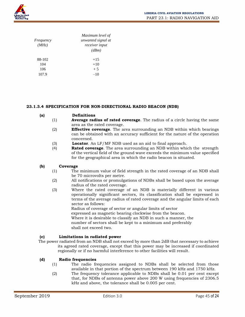
PART 23.1: RADIO NAVIGATION AID
September 2019 Edition 3.0 Page 45 of 24
LIBERIA CIVIL AVIATION REGULATIONS
Maximum level of
Frequency unwanted signal at
(MHz) receiver input
(dBm)
88-102 +15
104 +10
106 + 5
107.9 –10
SPECIFICATION FOR NON-DIRECTIONAL RADIO BEACON (NDB)
(a) Definitions (1) Average radius of rated coverage. The radius of a circle having the same
area as the rated coverage.
(2) Effective coverage. The area surrounding an NDB within which bearings can be obtained with an accuracy sufficient for the nature of the operation
concerned.
(3) Locator. An LF/MF NDB used as an aid to final approach.
(4) Rated coverage. The area surrounding an NDB within which the strength
of the vertical field of the ground wave exceeds the minimum value specified
for the geographical area in which the radio beacon is situated.
(b) Coverage
(1) The minimum value of field strength in the rated coverage of an NDB shall be 70 microvolts per metre.
(2) All notifications or promulgations of NDBs shall be based upon the average
radius of the rated coverage.
(3) Where the rated coverage of an NDB is materially different in various
operationally significant sectors, its classification shall be expressed in terms of the average radius of rated coverage and the angular limits of each
sector as follows:
Radius of coverage of sector or angular limits of sector
expressed as magnetic bearing clockwise from the beacon.
Where it is desirable to classify an NDB in such a manner, the
number of sectors shall be kept to a minimum and preferably
shall not exceed two.
(c) Limitations in radiated power The power radiated from an NDB shall not exceed by more than 2dB that necessary to achieve
its agreed rated coverage, except that this power may be increased if coordinated regionally or if no harmful interference to other facilities will result.
(d) Radio frequencies
(1) The radio frequencies assigned to NDBs shall be selected from those
available in that portion of the spectrum between 190 kHz and 1750 kHz. (2) The frequency tolerance applicable to NDBs shall be 0.01 per cent except
that, for NDBs of antenna power above 200 W using frequencies of 2306.5
kHz and above, the tolerance shall be 0.005 per cent.

PART 23.1: RADIO NAVIGATION AID
September 2019 Edition 3.0 Page 46 of 24
LIBERIA CIVIL AVIATION REGULATIONS
(3) Where two locators are used as supplements to an ILS, the frequency
separation between the carriers of the two shall be not less than 15 kHz. to
ensure correct operation of the radio compass, and preferably not more than
25 kHz in order to permit a quick tuning shift in cases where an aircraft has only one radio compass.
(4) Where locators associated with ILS facilities serving opposite ends of a single
runway are assigned a common frequency, provision shall be made to
ensure that the facility not in operational use cannot radiate. Note. — Additional guidance on the operation of locator beacons on common frequency channels
is contained in 23.5.3.3.2.2.
(e) Identification
(1) Each NDB shall be individually identified by a two- or three-letter
International Morse Code group transmitted at a rate corresponding to
approximately 7 words per minute.
(2) The complete identification shall be transmitted at least once every 30 seconds, except where the beacon identification is effected by on/off keying
of the carrier. In this latter case, the identification shall be at approximately
1- minute intervals, except that a shorter interval may be used at particular
NDB stations where this is found to be operationally desirable.
i) Except for those cases where the beacon identification is effected by on/off keying of the carrier, the identification signal shall be transmitted
at least three times each 30 seconds, spaced equally within that time
period.
(3) For NDBs with an average radius of rated coverage of 92.7 km (50 NM) or
less that are primarily approach and holding aids in the vicinity of an
aerodrome, the identification shall be transmitted at least three times each 30 seconds, spaced equally within that time period.
(4) The frequency of the modulating tone used for identification shall be 1020
Hz plus or minus 50 Hz or 400 Hz plus or minus 25 Hz.
(f) Characteristics of emissions (1) Except as provided in ((f) (2)), all NDBs shall radiate an uninterrupted carrier
and be identified by on/off keying of an amplitude modulating tone
(NON/A2A). (2) NDBs other than those wholly or partly serving as holding, approach and
landing aids, or those having an average radius of rated coverage of less
than 92.7 km (50 NM), may be identified by on/off keying of the
unmodulated carrier (NON/A1 A) if they are in areas of high beacon density
and/or where the required rated coverage is not practicable of achievement
because of: i) radio interference from radio stations;
ii) high atmospheric noise;
iii) local conditions.
(3) For each NDB identified by on/off keying of an audio modulating tone, the
depth of modulation shall be maintained as near to 95 percent as practicable.
(4) For each NDB identified by on/off keying of an audio modulating tone,
the characteristics of emission during identification shall be such as to
ensure satisfactory identification at the limit of its rated coverage.
(5) The carrier power of an NDB with NON/A2A emissions shall not fall when
the identity signal is being radiated except that, in the case of an NDB having an average radius of rated coverage exceeding 92.7 km (50 NM), a fall of not
more than 1.5 dB may be accepted,

PART 23.1: RADIO NAVIGATION AID
September 2019 Edition 3.0 Page 47 of 24
LIBERIA CIVIL AVIATION REGULATIONS
(6) Unwanted audio frequency modulations shall total less than 5 percent of
the amplitude of the carrier.
(7) The bandwidth of emissions and the level of spurious emissions shall be
kept at the lowest value that the state of technique and the nature of the service permit.
(g) Siting of locators (1) Where locators are used as a supplement to the ILS, they shall be located
at the sites of the outer and middle marker beacons. Where only one locator
is used as a supplement to the ILS, preference shall be given to location at
the site of the outer marker beacon. Where locators are employed as an aid
to final approach in the absence of an ILS, equivalent locations to those applying when an ILS is installed shall be selected, taking into account the
relevant obstacle clearance provisions of the Procedures for Air Navigation
Services —Aircraft Operations (Part 8).
(2) Where locators are installed at both the middle and outer marker positions,
they shall be located, where practicable, on the same side of the extended
centre line of the runway in order to provide a track between the locators which will be more nearly parallel to the centre line of the runway.
(h) Monitoring (1) For each NDB, suitable means shall be provided to enable detection of any
of the following conditions at an appropriate location:
i) decrease in radiated carrier power of more than 50 percent below that
required for the rated coverage;
ii) failure to transmit the identification signal; iii) malfunctioning or failure of the means of monitoring itself.
(2) When an NDB is operated from a power source having a frequency which is
close to airborne ADF equipment switching frequencies, and where the
design of the NDB is such that the power supply frequency is likely to appear
as a modulation product on the emission, the means of monitoring shall be capable of detecting such power supply modulation on the carrier in excess
of 5 percent.
(3) During the hours of service of a locator, the means of monitoring shall
provide for a continuous check on the functioning of the locator as
prescribed in 23.1.3.4 (h) (1) above. (4) During the hours of service of an NDB other than a locator, the means of
monitoring shall provide for a continuous check on the functioning of
the NDB as prescribed in 23.1.3.4 (h) (1).
SPECIFICATION FOR UHF DISTANCE MEASURING EQUIPMENT (DME)
(a) Definitions
(1) Control motion noise (CMN). That portion of the guidance signal error which causes control surface, wheel and column motion and could affect
aircraft attitude angle during coupled flight, but does not cause aircraft
displacement from the desired course and or glide path.
(2) DME dead time. A period immediately following the decoding of a valid
interrogation during which a received interrogation will not cause a reply to
be generated. (3) DME/N. Distance measuring equipment, primarily serving operational
needs of en-route or TMA navigation, where the "N" stands for narrow
spectrum characteristics (to be distinguished from "W").

PART 23.1: RADIO NAVIGATION AID
September 2019 Edition 3.0 Page 48 of 24
LIBERIA CIVIL AVIATION REGULATIONS
(4) DME/P. The distance measuring element of the MLS, where the "P" stands
for precise distance measurement. The spectrum characteristics are those
of DME/N.
(5) DME/W. Distance measuring equipment, primarily serving operational needs of en-route or TMA navigation, where the "W" stands for wide
spectrum characteristics (to be distinguished from "N").
(6) Equivalent isotropically radiated power (e.i.r.p.). The product of the
power supplied to the antenna and the antenna gain in a given direction
relative to an isotropic antenna (absolute or isotropic gain). (7) Final approach (FA) mode. The condition of DME/P operation which
supports flight operations in the final approach and runway regions.
(8) Initial approach (IA) mode. The condition of DMEyp operation which
supports those flight operations outside the final approach region and which
is interoperable with DME/N.
(9) Key down time. The time during which a dot or dash of a Morse character is being transmitted.
(10) MLS approach reference datum. A point on the minimum glide path at a
specified height above the threshold. (See 23.1.3.10 below.)
(11) MLS datum point. The point on the runway centre line closest to the phase
centre of the approach elevation antenna. (See 23.1.3.10 below.)
(12) Mode W, X, Y, Z. A method of coding the DME transmissions by time spacing pulses of a pulse pair, so that each frequency can be used more
than once.
(13) Partial rise time. The time as measured between the 5 and 30 per cent
amplitude points on the leading edge of the pulse envelope, i.e. between
points h and i on Figures 3-1 and 3-2. (14) Path following error (PFE). That portion of the guidance signal error which
could cause aircraft displacement from the desired course and/or glide
path. (See 23.1.3.10 below.)
(15) Pulse amplitude. The maximum voltage of the pulse envelope, i.e. A in
Figure 3-1.
(16) Pulse decay time. The time as measured between the 90 and 10 per cent amplitude points on the trailing edge of the pulse envelope, i.e. between
points e and g on Figure 3-1.
(17) Pulse code. The method of differentiating between W, X, Y and Z modes and
between FA and IA modes.
(18) Pulse duration. The time interval between the 50 per cent amplitude point on leading and trailing edges of the pulse envelope, i.e. between points b
and f on Figure 3-1.
(19) Pulse rise time. The time as measured between the 10 and 90 per cent
amplitude points on the leading edge of the pulse envelope, i.e. between
points a and c on Figure 3-1.
(20) Reply efficiency. The ratio of replies transmitted by the transponder to the total of received valid interrogations.
(21) Search. The condition which exists when the DME interrogator is
attempting to acquire and lock onto the response to its own interrogations
from the selected transponder,
(22) System efficiency. The ratio of valid replies processed by the interrogator to the total of its own interrogations.
(23) Track. The condition which exists when the DME interrogator has locked
onto replies in response to its own interrogations, and is continuously
providing a distance measurement.
(24) Transmission rate. The average number of pulse pairs transmitted from
the transponder per second.

PART 23.1: RADIO NAVIGATION AID
September 2019 Edition 3.0 Page 49 of 24
LIBERIA CIVIL AVIATION REGULATIONS
(25) Virtual origin. The point at which the straight line through the 30 per cent
and 5 per cent amplitude points on the pulse leading edge intersects the 0
per cent amplitude axis (see Figure 3-2).
(b) General (1) The DME system shall provide for continuous and accurate indication in the
cockpit of the slant range distance of an equipped aircraft from an equipped ground reference point.
(2) The system shall comprise two basic components, one fitted in the aircraft,
the other installed on the ground. The aircraft component shall be referred
to as the interrogator and the ground component as the transponder.
(3) In operation interrogators shall interrogate transponders which shall, in turn, transmit to the interrogator replies synchronized with the
interrogations, thus providing means for accurate measurement of distance.
(4) DME/P shall have two operating modes, IA and FA.

PART 23.1: RADIO NAVIGATION AID
September 2019 Edition 3.0 Page 50 of 24
LIBERIA CIVIL AVIATION REGULATIONS
(5) When a DME is associated with an ILS, MLS or VOR for the purpose of
constituting a single facility, they shall: i) be operated on a standard frequency pairing in accordance with
23.1.3.5(8) below;
ii) be collocated within the limits prescribed for associated facilities in
23.1.3.5(6) below; and
iii) comply with the identification provisions of 23.1.3.5(9)(ix) below.
(6) Collocation limits for a DME facility associated with an ILS, MLS or VOR facility
(7) Associated VOR and DME facilities shall be collocated in accordance with
the following:
i) for those facilities used in terminal areas for approach purposes or other
procedures where the highest position fixing accuracy of system capability is required, the separation of the VOR and DME antennas
does not exceed 80 m (260 ft);
ii) for purposes other than those indicated in a), the separation of the VOR
and DME antennas does not exceed 600 m (2 000 ft). (8) Association of DME with ILS
Guidance on the association of DME with ILS are specified in IS: 23.1.3.5 (b) (6) (ii)
(9) Association of DME with MLS
i) If a DME/P is used to provide ranging information, it shall be sited as
close as possible to the MLS azimuth facility. (10) The Provisions in 23.1.3.5 (c), 23.1.3.5 (d) and 23.1.3.5 (e) denoted by ‡ shall
apply only to DME equipment first installed after 1 January 1989.
(c) System characteristics
(1) Performance

PART 23.1: RADIO NAVIGATION AID
September 2019 Edition 3.0 Page 51 of 24
LIBERIA CIVIL AVIATION REGULATIONS
i) Range. The system shall provide a means of measurement of slant range
distance from an aircraft to a selected transponder to the limit of
coverage prescribed by the operational requirements for the selected
transponder. ii) Coverage
A. When associated with a VOR, DME/N coverage shall be at least that
of the VOR to the extent practicable.
B. When associated with either an ILS or an MLS, DME/N coverage
shall be at least that of the respective ILS or of the MLS azimuth angle guidance coverage sectors.
C. DME/P coverage shall be at least that provided by the MLS azimuth
angle guidance coverage sectors.
iii) Accuracy
A. System accuracy. The accuracy standards specified in 23.1.3.5 (c)
(1) (iv), 23.1.3.5 (d) (5) and 23.1.3.5 (e) (4) shall be met on a 95 per cent probability basis.
iv) DME/P accuracy
A. Error components. The path following error (PFE) shall be
comprised of those frequency components of the DME/P error at
the output of the interrogator which lie below 1.5 rad/s. The control motion noise (CMN) shall be comprised of those frequency
components of the DME/P error at the output of the interrogator
which lie between 0.5 rad/s and 10 rad/s.
B. Errors on the extended runway centre line shall not exceed the
values given in Table B at the end of this Subpart. C. In the approach sector, away from the extended runway centre line,
the allowable PFE for both standard 1 and standard 2 shall be
permitted to increase linearly with angle up to plus or minus 40
degrees MLS azimuth angle where the permitted error is 1.5 times
that on the extended runway centre line at the same distance. The
allowable CMN shall not increase with angle. There shall be no degradation of either PEE or CMN with elevation angle.
(2) Radio frequencies and polarization. The system shall operate with vertical
polarization in the frequency band 960 MHz to 1215 MHz. The interrogation and reply frequencies shall be assigned with 1-MHz spacing between channels.
(3) Channelling
i) DME operating channels shall be formed by pairing interrogation and reply frequencies and by pulse coding on the paired frequencies.
ii) Pulse coding. DME/P channels shall have two different interrogation pulse codes as shown in the table of 23.1.3.5.4.4.1.One shall be used
in the initial approach (IA) mode; the other shall be used in the final approach (FA) mode.
iii) DME operating channels shall be chosen from Table A (located at the
end of this Subpart), of 352 channels in which the channel numbers, frequencies, and pulse codes are assigned.
iv) Channel pairing. When a DME transponder is intended to operate in association with a single VHF navigation facility in the 108 MHz to 117.95 MHz frequency band and/or an MLS angle facility in the 5 031.0
MHz to 5 090.7 MHz frequency band, the DME operating channel shall be paired with the VHF channel and/or MLS angle frequency as given
in Table A. Note.— There may be instances when a DME channel will be

PART 23.1: RADIO NAVIGATION AID
September 2019 Edition 3.0 Page 52 of 24
LIBERIA CIVIL AVIATION REGULATIONS
paired with both the ILS frequency and an MLS channel (see
Subpart 23.5.4.3 of this Part).
(4) Interrogation pulse repetition frequency
Note.— If the interrogator operates on more than one channel in one second, the following specifications apply to the sum of interrogations on all channels.
i) DME/N. The interrogator average pulse repetition frequency (PRF) shall not exceed 30 pairs of pulses per second, based on the assumption
that at least 95 per cent of the time is occupied for tracking. ii) DME/N. If it is desired to decrease the time of search, the PRF may be
increased during search but shall not exceed 150 pairs of pulses per
second. iii) DME/N. After 15 000 pairs of pulses have been transmitted without
acquiring indication of distance, the PRF shall not exceed 60 pairs of pulses per second thereafter, until a change in operating channel is made or successful search is completed.
iv) DME/N. When, after a time period of 30 seconds, tracking has not been established the pulse pair repetition frequency shall not exceed 30 pulse
pairs per second thereafter. v) DME/P. The interrogator pulse repetition frequency shall not exceed the
following number of pulse pairs per second:
A. search 40
B. aircraft on the ground 5
C. initial approach mode track 23 D. final approach mode track 40
(5) Aircraft handling capacity of the system
i) The aircraft handling capacity of transponders in an area shall be adequate for the peak traffic of the area or 100 aircraft, whichever is the
lesser. ii) Where the peak traffic in an area exceeds 100 aircraft, the transponder
shall be capable of handling that peak traffic.
(6) Transponder identification
i) All transponders shall transmit an identification signal in one of the following forms as required by 23.1.3.5.3.6.5 below:
A. an "independent" identification consisting of coded
(International Morse Code) identity pulses which can be used
with all transponders;
B. an "associated" signal which can be used for transponders
specifically associated with a VHP navigation or an MLS angle guidance facility which itself transmits an identification signal.
Note.— An MLS angle guidance facility provides its identification as a digital word transmitted on the data channel into the approach and back azimuth coverage regions as specified in 23.1.3.10 (d) (6) (ii) (A).
ii) Both systems of identification shall use signals, which shall consist of the transmission for an appropriate period of a series of paired pulses transmitted at a repetition rate of 1 350 pulse pairs per second, and
shall temporarily replace all reply pulses that would normally occur at

PART 23.1: RADIO NAVIGATION AID
September 2019 Edition 3.0 Page 53 of 24
LIBERIA CIVIL AVIATION REGULATIONS
that time except as in 23.1.3.5 (c) (6) (ii) (B) below. These pulses shall
have similar characteristics to the other pulses of the reply signals. A. DME/N. Reply pulses shall be transmitted between key down
times.
B. DME/N. If it is desired to preserve a constant duty cycle, an equalizing pair of pulses, having the same characteristics as
the identification pulse pairs, shall be transmitted 100
microseconds plus or minus 10 microseconds after each
identity pair.
C. DME/P. Reply pulses shall be transmitted between key down
times. D. For the DME/P transponder, reply pulse pairs to valid FA mode
interrogations shall also be transmitted during key down times
and have priority over identification pulse pairs.
E. The DME/P transponder shall not employ the equalizing pair
of pulses of 23.1.3.5 (c) (6) (ii) (B) above. iii) The characteristics of the "independent" identification signal shall be as
follows: A. the identity signal shall consist of the transmission of the
beacon code in the form of dots and dashes (International
Morse Code) of identity pulses at least once every 40 seconds,
at a rate of at least 6 words per minute; and
B. the identification code characteristic and letter rate for the DME, transponder shall conform to the following to ensure that
the maximum total key down time does not exceed 5 seconds
per identification code group. The dots shall be a time duration
of 0.1 second to 0.230 second. The dashes shall be typically 3
times the duration of the dots. The duration between dots and/or dashes shall be equal to that of one dot plus or minus
10 per cent. The time duration between letters or numerals
shall not be less than three dots. The total period for
transmission of an identification code group shall not exceed
10 seconds.
Note.— The tone identification signal is transmitted at a repetition rate of 1 350 pps. This frequency may be used directly in the airborne equipment as an aural output for the pilot, or other frequencies may be generated at the option of the interrogator designer (see 23.1.3.5 (c) (6) (ii).
iv) The characteristics of the "associated" signal shall be as follows:
A. when associated with a VHF or an MLS angle facility, the identification shall be transmitted in the form of dots and
dashes (International Morse Code) as in 23.1.3.5.3,6.3 above
and shall be synchronized with the VHF facility identification
code;
B. each 40-second interval shall be divided into four or more
equal periods, with the transponder identification transmitted during one period only and the associated VHF and MLS angle
facility identification, where these are provided, transmitted
during the remaining periods;
C. for a DME transponder associated with an MLS, the
identification shall be the last three letters of the MLS angle facility identification specified in 23.1.3.10 (d) (6) (ii) (A) below.
v) Identification implementation

PART 23.1: RADIO NAVIGATION AID
September 2019 Edition 3.0 Page 54 of 24
LIBERIA CIVIL AVIATION REGULATIONS
A. The "independent" identification code shall be employed
wherever a transponder is not specifically associated with a
VHF navigational facility or an MLS facility. B. Wherever a transponder is specifically associated with a VHF
navigational facility or an MLS facility, identification shall be
provided by the "associated" code.
C. When voice communications are being radiated on an
associated VHF navigational facility, an "associated" signal from the transponder shall not be suppressed.
(7) DME/P mode transition
i) The DME/P interrogator for Standard 1 accuracy shall change from IA mode track to FA mode track at 13 km (7 NM) from the transponder
when approaching the transponder, or any other situation when within 13 km (7 NM).
ii) For Standard 1 accuracy, the transition from IA mode to FA mode track operation may be initiated within 14.8 km (8 NM) from the transponder.
Outside 14.8 km (8 NM), the interrogator shall not interrogate in the FA mode.
Note. — Paragraph 23.1.3.5. (c) (7) (i) does not apply if the transponder is a DME/N or if the DME/P transponder FA mode is inoperative.
(8) System efficiency. The DME/P system accuracy of 23.1.3.5(c) (1) (iii) (D)
above shall be achieved with a system efficiency of 50 per cent or more.
(d) Detailed technical characteristics of transponder and associated monitor
(1) Transmitter
i) Frequency of operation. The transponder shall transmit on the reply
frequency appropriate to the assigned DME channel (see 23.1.3.5(c) (1) (iii) (C) above).
ii) Frequency stability. The radio frequency of operation shall not vary more than plus or minus 0.002 per cent from the assigned frequency.
iii) Pulse shape and spectrum. The following shall apply to all radiated pulses:
* Pulse rise time. A. DME/N. Pulse rise time shall not exceed 3 microseconds.
B. DME/P. Pulse rise time shall not exceed 1.6 microseconds. For
the FA mode, the pulse shall have a partial rise time of 0.25
plus or minus 0.05microsecond. With respect to the FA mode and accuracy standard 1, the slope of the pulse in the partial
rise time shall not vary by more than plus or minus 20 per
cent. For accuracy standard 2, the slope shall not vary by more
than plus or minus 10 per cent.
C. DME/P. Pulse rise time shall not exceed 1.2 microseconds.
D. Pulse duration shall be 3.5 microseconds plus or minus 0.5 microsecond.
E. Pulse decay time shall nominally be 2.5 microseconds but shall
not exceed 3.5 microseconds
F. The instantaneous amplitude of the pulse shall not, at any instant between the point of the leading edge which is 95 per

PART 23.1: RADIO NAVIGATION AID
September 2019 Edition 3.0 Page 55 of 24
LIBERIA CIVIL AVIATION REGULATIONS
cent of maximum amplitude and the point of the trailing edge
which is 95 per cent of the maximum amplitude, fall below a
value which is 95 per cent of the maximum voltage amplitude
of the pulse. G. For DME/N and DME/P: the spectrum of the pulse modulated
signal shall be such that during the pulse the effective radiated
power contained in a 0.5 MHz band centred on frequencies 0.8
MHz above and 0.8 MHz below the nominal channel frequency
in each case shall not exceed 200 mW, and the effective radiated power contained in a 0.5 MHz band centred on
frequencies 2 MHz above and 2 MHz below the nominal
channel frequency in each case shall not exceed 2 mW. The
effective radiated power contained within any 0.5 MHz band
shall decrease monotonically as the band centre frequency
moves away from the nominal channel frequency. H. For DME/W, the spectrum of the pulse modulated signal shall
be such that during the pulse the effective radiated power
contained in a 0.5 MHz band centred on frequencies 1.8 MHz
above and 1.8 MHz below the nominal channel frequency in
each case shall not exceed 200 mW, and the effective radiated
power contained in a 0.5 MHz band centred on frequencies 3 MHz above and 3 MHz below the nominal channel frequency in
each case shall not exceed 2 mW. Any lobe of the spectrum
shall be of less amplitude than the adjacent lobe nearer the
nominal channel frequency.
I. To ensure proper operation of the thresholding techniques, the instantaneous magnitude of any pulse turn-on transients
which occur in time prior to the virtual origin shall be less than
one per cent of the pulse peak amplitude. Initiation of the turn-
on process shall not commence sooner than 1 microsecond
prior to the virtual origin.
iv) Pulse spacing
A. The spacing of the constituent pulses of transmitted pulse pairs shall be as given in the table in 23.1.3.5 (d) (4) (i).
B. DME/N. The tolerance on the pulse spacing shall be plus or
minus 0.25 microseconds.
C. DME/N. The tolerance on the DME/N pulse spacing shall be
plus or minus 0.10 microsecond.
D. DME/P. The tolerance on the pulse spacing shall be plus or minus 0.10 microseconds.
E. The pulse spacings shall be measured between the half voltage
points on the leading edges of the pulses.
v) Peak power output A. DME/N. The peak effective radiated power shall not be less
than that required to ensure a peak pulse power density of
approximately minus 83 dBW/m² at the maximum specified
service range and level. B. DME/N. The peak equivalent isotropically radiated power shall
not be less than that required to ensure a peak pulse power
density of minus 89 dB W/ m² under all operational weather

PART 23.1: RADIO NAVIGATION AID
September 2019 Edition 3.0 Page 56 of 24
LIBERIA CIVIL AVIATION REGULATIONS
conditions at any point within coverage specified in 23.1.3.5 (c)
(1) (ii) above.
C. DME/P. The peak equivalent isotropically radiated power shall
not be less than that required to ensure the following peak pulse power densities under all operational weather
conditions:
D. minus 89 dBW/m2 at any point within the coverage specified
in 23.1.3.5 (c) (1) (ii)above at ranges greater than 13 km (7 NM)
from the transponder antenna; E. minus 75 dBW/m2 at any point within the coverage specified
in 23.1.3.5 (c) (1) (ii)above at ranges less than 13 km (7 NM)
from the transponder antenna;
F. minus 70 dBW/m2 at the MLS approach reference datum;
G. minus 79 dBW/m2 at 2.5 m (8 ft) above the runway surface,
at the MLS datum point, or at the farthest point on the runway centre line which is in line of sight of the DME transponder
antenna.
H. The peak power of the constituent pulses of any pair of pulses
shall not differ by more than 1 dB.
I. The reply capability of the transmitter shall be such that the
transponder shall be capable of continuous operation at a transmission rate of 2700 plus or minus 90 pulse pairs per
second (if 100 aircraft are to be served).
J. The transmitter shall operate at a transmission rate, including
randomly distributed pulse pairs and distance reply pulse
pairs, of not less than 700 pulse pairs per second except during identity. The minimum transmission rate shall be as close as
practicable to 700 pulse pairs per second. For DME/P, in no
case shall it exceed 1200 pulse pairs per second.
vi) Spurious radiation. During intervals between transmission of individual pulses, the spurious power received and measured in a receiver having
the same characteristics as a transponder receiver, but tuned to any DME interrogation or reply frequency, shall be more than 50 dB below
the peak pulse power received and measured in the same receiver tuned to the reply frequency in use during the transmission of the required pulses. This provision refers to all spurious transmissions, including
modulator and electrical interference. A. DME/N. The spurious power level specified in 23.1.3.5 (d) (1)
(vi) above shall be more than 80 dB below the peak pulse power
level.
B. DME/P. The spurious power level specified in 23.1.3.5 (d) (1) (vi) above shall be more than 80 dB below the peak pulse power
level.
C. Out-of-band spurious radiation. At all frequencies from 10 to
1800MHz, but excluding the band of frequencies from 960 to
1 215 MHz, the spurious output of the DME transponder
transmitter shall not exceed minus 40 dBm in any one kHz of receiver bandwidth.
D. The equivalent isotropically radiated power of any CW
harmonic of the carrier frequency on any DME operating
channel shall not exceed minus 10 dBm.
(2) Receiver

PART 23.1: RADIO NAVIGATION AID
September 2019 Edition 3.0 Page 57 of 24
LIBERIA CIVIL AVIATION REGULATIONS
i) Frequency of operation. The receiver centre frequency shall be the
interrogation frequency appropriate to the assigned DME operating channel (see 23.1.3.5 (c) (3) (iii) above).
ii) Frequency stability. The centre frequency of the receiver shall not vary
more than plus or minus 0.002 per cent from the assigned frequency. iii) Transponder sensitivity
A. In the absence of all interrogation pulse pairs, with the exception of those necessary to perform the sensitivity
measurement, interrogation pulse pairs with the correct
spacing and nominal frequency shall trigger the transponder if
the peak power density at the transponder antenna is at least:
B. minus 103 dBW/m2 for DME/N with coverage range greater
than 56 km (30 NM); C. minus 93 dBW/m2 for DME/N with coverage range not greater
than 56 km (30 NM);
D. minus 86 dBW/m2 for DME/P IA mode;
E. minus 75 dBW/m2 for DME/P FA mode.
F. The minimum power densities specified in 23.1.3.5 (d) (2) (iii)
(A) above shall cause the transponder to reply with an
efficiency of at least:
G. 70 per cent for DME/N;
H. 70 per cent for DME/P IA mode; I. 80 per cent for DME/P FA mode.
J. ‡DME/N dynamic range. The performance of the transponder
shall be maintained when the power density of the
interrogation signal at the transponder antenna has any value
between the minimum up to a maximum of minus 22 dBW/m2 when installed with ILS or MLS and minus 35 dBW/m2 when
installed for other applications.
K. DME/P dynamic range. The performance of the transponder
shall be maintained when the power density of the
interrogation signal at the transponder antenna has any value
between the minimum up to a maximum of minus 22 dBW/m². L. The transponder sensitivity level shall not vary by more than 1
dB for transponder loadings between 0 and 90 per cent of its
maximum transmission rate.
M. ‡DME/N. When the spacing of an interrogator pulse pair varies
from the nominal value by up to plus or minus 1 microsecond, the receiver sensitivity shall not be reduced by more than 1 dB.
N. DME/P. When the spacing of an interrogator pulse pair varies
from the nominal value by up to plus or minus 1 microsecond,
the receiver sensitivity shall not be reduced by more than 1 dB.
iv) Load limiting A. DME/N. When transponder loading exceeds 90 per cent of the
maximum transmission rate, the receiver sensitivity shall be
automatically reduced in order to limit the transponder replies, so as to ensure that the maximum permissible transmission
rate is not exceeded. (The available range of sensitivity
reduction shall be at least 50 dB.)

PART 23.1: RADIO NAVIGATION AID
September 2019 Edition 3.0 Page 58 of 24
LIBERIA CIVIL AVIATION REGULATIONS
B. DME/P. To prevent transponder overloading the transponder
shall automatically limit its replies, so as to ensure that the
maximum transmission rate is not exceeded. If the receiver
sensitivity reduction is implemented to meet this requirement, it shall be applied to the IA mode only and shall not affect the
FA mode.
v) Noise. When the receiver is interrogated at the power densities specified in 23.1.3.5 (d) (2) (iii) (A)above to produce a transmission rate equal to
90 per cent of the maximum, the noise generated pulse pairs shall not exceed 5 per cent of the maximum transmission rate.
vi) Bandwidth
A. The minimum permissible bandwidth of the receiver shall be such that the transponder sensitivity level shall not deteriorate
by more than 3 dB when the total receiver drift is added to an
incoming interrogation frequency drift of plus or minus 100
kHz.
B. DME/N. The receiver bandwidth shall be sufficient to allow compliance with 23.1.3.5 (c) (1) (iii) above when the input
signals are those specified in 23.1.3.5 (e) (1) (iii) below.
C. DME/P — IA mode. The receiver bandwidth shall be sufficient
to allow compliance 23.1.3.5 (c) (1) (iii above when the input
signals are those specified in 23.1.3.5 (c) (1) (iii below. The 12
dB bandwidth shall not exceed 2 MHz and the 60 dB bandwidth shall not exceed 10 MHz.
D. DME/P — FA mode. The receiver bandwidth shall be sufficient
to allow compliance with 23.1.3.5 (c) (1) (iii above when the
input signals are those specified in 23.1.3.5 (e) (1) (iii)
below. The 12 dB bandwidth shall not exceed 6 MHz and the 60 dB bandwidth shall not exceed 20 MHz.
E. Signals greater than 900 kHz removed from the desired
channel nominal frequency and having power densities up to
the values specified in 23.1.3.5 (d) (3) (iii) for DME/N and
23.1.3.5 (d) (3) (iv) for DME/P shall not trigger the transponder.
Signals arriving at the intermediate frequency shall be suppressed at least 80 dB. All other spurious response or
signals within the 960 MHz to 1 215 MHz band and image
frequencies shall be suppressed at least 75 dB.
vii) Recovery time. Within 8 microseconds of the reception of a signal between 0 dB and 60 dB above minimum sensitivity level, the minimum
sensitivity level of the transponder to a desired signal shall be within 3 dB of the value obtained in the absence of signals. This requirement shall be met with echo suppression circuits, if any, rendered inoperative. The 8
microseconds are to be measured between the half voltage points on the leading edges of the two signals, both of which conform in shape, with the
specifications in 23.1.3.5 (e) (1) (iii) below. viii) Spurious radiations. Radiation from any part of the receiver or allied circuits
shall meet the requirements stated in 23.1.3.5 (d) (3) (vi) above. ix) CW and echo suppression
A. CW and echo suppression shall be adequate for the sites at which
the transponders will be used.
x) Protection against interference A. Protection against interference outside the DME frequency band
shall be adequate for the sites at which the transponders will be
used.

PART 23.1: RADIO NAVIGATION AID
September 2019 Edition 3.0 Page 59 of 24
LIBERIA CIVIL AVIATION REGULATIONS
(3) Decoding
i) The transponder shall include a decoding circuit such that the transponder can be triggered only by pairs of received pulses having
pulse duration and pulse spacings appropriate to interrogator signals as described in 23.1.3.5 (e) (1) (iii) and 23.1.3.5 (e) (1) (iv) below.
ii) The decoding circuit performance shall not be affected by signals arriving before, between, or after, the constituent pulses of a pair of the correct spacing.
iii) ‡DME/N — Decoder rejection. An interrogation pulse pair with a spacing of plus or minus 2 microseconds, or more, from the nominal
value and with any signal level up to the value specified in 23.1.3.5 (d) (2) (iii) (C) shall be rejected such that the transmission rate does not exceed the value obtained when interrogations are absent.
iv) DME/P— Decoder rejection. An interrogation pulse pair with a spacing of plus or minus 2 microseconds, or more, from the nominal value and
with any signal level up to the value specified in 23.1.3.5.4.2.3.4 shall be rejected such that the transmission rate docs not exceed the value obtained when interrogations are absent.
(4) Time delay
i) When a DME is associated only with a VHP facility, the time delay shall be the interval from the half voltage point on the leading edge of the second constituent pulse of the interrogation pair and the half voltage
point on the leading edge of the second constituent pulse of the reply transmission. This delay shall be consistent with the following table,
when it is desired that aircraft interrogators are to indicate distance from the transponder site.
Pulse pair
spacing (µs) Time delay (µs)
Channel 1st pulse 2nd pulse
suffix Operating mode Interrogation Reply timing timing
X DME/N 12 12 50 50
DME/P IA M 12 12 50 –
DME/P FA M 18 12 56 –
Y DME/N 36 30 56 50
DME/P IA M 36 30 56 –
DME/P FA M 42 30 62 –
W DME/N – – – –
DME/P IA M 24 24 50 –
DME/P FA M 30 24 56 –
Z DME/N – – – –
DME/P IA M 21 15 56 –
DME/P FA M 27 15 62 –

PART 23.1: RADIO NAVIGATION AID
September 2019 Edition 3.0 Page 60 of 24
LIBERIA CIVIL AVIATION REGULATIONS
Note 1.— W and X are multiplexed on the same frequency.
Note 2.— Z and Y are multiplexed on the same frequency.
ii) When a DME is associated with an MLS angle facility, the time delay
shall be the interval from the half voltage point on the leading edge of the first constituent pulse of the interrogation pair and the half voltage point on the leading edge of the first constituent pulse of the reply
transmission. This delay shall be 50 microseconds for mode X channels and 56 microseconds for mode Y channels, when it is desired that
aircraft interrogators are to indicate distance from the transponder site. A. For DME/P transponders, no time delay adjustment shall be
permitted.
iii) For the DME/N the transponder time delay shall be capable of being set to an appropriate value between the nominal value of the time delay
minus 15 microseconds and the nominal value of the time delay, to permit aircraft interrogators to indicate zero distance at a specific point remote from the transponder site.
A. DME/N. The time delay shall be the interval from the half voltage point on the leading edge of the first constituent pulse
of the interrogation pair and the half voltage point on the leading edge of the first constituent pulse of the reply transmission.
B. DME/P — IA mode. The time delay shall be the interval from the half voltage point on the leading edge of the first
constituent pulse of the interrogation pulse pair to the half voltage point on the leading edge of the first constituent pulse of the reply pulse pair.
C. DME/P — FA mode. The time delay shall be the interval from thevirtual origin of the first constituent pulse of the
interrogation pulse pair to the virtual origin of the first constituent pulse of the reply pulse pair. The time of arrival
measurement points shall be within the partial rise time of the first constituent pulse of the pulse pair in each case.
D. DME/N. Transponders shall be sited as near to the point at
which zero indication is required as is practicable.
(5) Accuracy
i) DME/N. The transponder shall not contribute more than plus or minus 1 microsecond (150 m (500 ft)) to the over-all system error.
A. DME/N. The contribution to the total system error due to the combination of the transponder errors, transponder location
coordinate errors, propagation effects and random pulse interference effects shall be not greater than plus or minus 340 m (0.183 NM) plus 1.25 per cent of distance measure.
Note.— This error contribution limit includes errors from all causes except the airborne equipment, and assumes that the airborne equipment measures time delay based on the first constituent pulse of a pulse pair.
B. DME/N. The combination of the transponder errors,
transponder location coordinate errors, propagation effects and random pulse interference effects shall not contribute

PART 23.1: RADIO NAVIGATION AID
September 2019 Edition 3.0 Page 61 of 24
LIBERIA CIVIL AVIATION REGULATIONS
more than plus or minus 185 m (0.1 NM) to the overall system
error.
Note. — This error contribution limit includes errors from all causes except the airborne equipment, and assumes that the airborne equipment measures time delay based on the first constituent pulse of a pulse pair.
ii) ‡DME/N. A transponder associated with a landing aid shall not contribute more than plus or minus 0.5 microsecond (75 m (250 ft)) to the over-all system error.
iii) DME/P — FA mode
A. Accuracy standard 1. The transponder shall not contribute more than plus or minus 10m (plus or minus 33 ft) PFE and plus or minus 8 m (plus or minus 26 ft) CMN to the over-all
system error.
B. Accuracy standard 2. The transponder shall not contribute
more than plus or minus 5 m (plus or minus 23 ft) PFE and plus or minus 5 m (plus or minus 23 ft) CMN to the over-all system error.
iv) DME/P — IA mode. The transponder shall not contribute more than
plus or minus 15m (plus or minus 50 ft) PFE and plus or minus 10 m (plus or minus 33 ft) CMN to the over-all system error.
v) When a DME is associated with an MLS angle facility, the above accuracy shall include the error introduced by the first pulse detection
due to the pulse spacing tolerances.
(6) Efficiency
i) The transponder reply efficiency shall be at least 70 per cent for DME/N and DME/P (IA mode) and 80 per cent for DME/P (FA mode) at all values of transponder loading up to the loading corresponding to 23.1.3.5 (c)
(5) above and at the minimum sensitivity level specified in 23.1.3.5 (d) (2) (iii) (A) and 23.1.3.5 (d) (2) (iii) (E) above.
ii) Transponder dead time. The transponder shall be rendered inoperative for a period
normally not to exceed 60 microseconds after a valid interrogation decode has occurred. In extreme cases when the geographical site of the transponder is such as to produce undesirable reflection problems, the dead time may be increased but only by the
minimum amount necessary to allow the suppression of echoes for DME/N and DME/P IA mode.

PART 23.1: RADIO NAVIGATION AID
September 2019 Edition 3.0 Page 62 of 24
LIBERIA CIVIL AVIATION REGULATIONS
A. In DME/P the IA mode dead time shall not blank the FA mode channel and vice versa.
(7) Monitoring and control
i) Means shall be provided at each transponder site for the automatic monitoring and
control of the transponder in use. ii) DME/N monitoring action
A. In the event that any of the conditions specified in 23.1.3.5 (d) (7) (ii) (B) below occur, the monitor shall cause the following action to take place:
* a suitable indication shall be given at a control point;
* the operating transponder shall be automatically switched off; and * the standby transponder, if provided, shall be automatically placed in operation.
B. The monitor shall cause the actions specified in 23.1.3.5 (d) (7) (ii) (A) above if: * the transponder delay differs from the assigned value by 1 microsecond (150 m (500 ft))
or more;
* in the case of a DME/N associated with a landing aid, the transponder delay differs from the assigned value by 0.5 microsecond (75 m (250 ft)) or more.
C. The monitor shall cause the actions specified in 23.1.3.5 (d) (7) (ii) (A) above if the spacing between the first and second pulse of the transponder pulse pair differs from the nominal value specified in the table following 23.1. 3.5 (d) (4) (i) above by 1
microsecond or more. D. The monitor shall also cause a suitable indication to be given at a control point if any
of the following conditions arise: * a fall of 3 dB or more in transponder transmitted power output;
* a fall of 6 dB or more in the minimum transponder receiver sensitivity (provided that this is not due to the action of the receiver automatic gain reduction circuits);
* the spacing between the first and second pulse of the transponder reply pulse pair
differs from the normal value specified in 23.1.3.5 (d) (1) (iv) above by 1 microsecond or more;
* variation of the transponder receiver and transmitter frequencies beyond the control range of the reference circuits (if the operating frequencies are not directly crystal controlled).
E. Means shall be provided so that any of the conditions and malfunctioning enumerated in 23.1.3.5.4.7.2.2, 23.1.3.5.4.7.2.3 and 23.1.3.5.4.7.2.4 above which are monitored
can persist for a certain period before the monitor takes action. This period shall be as low as practicable, but shall not exceed 10 seconds, consistent with the need for avoiding interruption, due to transient effects, of the service provided by the
transponder.
F. 23.1.3.5.4.7.2.6 The transponder shall not be triggered more than 120 times per second for either monitoring or automatic frequency control purposes, or both.
iii) DME/P monitoring action
A. The monitor system shall cause the transponder radiation to cease and provide a warning at a control point if any of the following conditions persist for longer than the period specified:
* there is a change in transponder PFE that exceeds the limits specified in either 23.1.3.5 (d) (5) (ii) or 23.1.3.5 (d) (5) (ii) (A) above for more than one second. If the FA mode limit
is exceeded, but the IA mode limit is maintained, the IA mode may remain operative;

PART 23.1: RADIO NAVIGATION AID
September 2019 Edition 3.0 Page 63 of 24
LIBERIA CIVIL AVIATION REGULATIONS
* there is a reduction in the effective radiated power to less than that necessary to satisfy
the requirements specified in 23.1.3.5 (d) (1) (v) (C) above for a period of more than one second;
* there is a reduction of 3 dB or more in the transponder sensitivity necessary to satisfy
the requirements specified in 23.1.3.5 (d) (2) (iii) above for a period of more than five seconds in FA mode and ten seconds in IA mode (provided that this is not due to the
action of the receiver automatic sensitivity reduction circuits); * the spacing between the first and second pulse of the transponder reply pulse pair
differs from the value specified in the table in 23.1.3.5 (d) (4) (i) above by 0.25
microsecond or more for a period of more than one second. B. The monitor shall cause a suitable indication to be given at a control point if there is an
increase above 0.3 microseconds or a decrease below 0.2 microseconds of the reply pulse partial rise time which persists for more than one second.
C. The period during which erroneous guidance information is radiated shall not exceed
the periods specified in 23.1.3.5 (d) (7) (iii) (A) above. Attempts to clear a fault by resetting the primary ground equipment or by switching to standby ground equipment,
if fitted, shall be completed within this time. If the fault is not cleared within the time allowed, the radiation shall cease. After shutdown, no attempt shall be made to restore
service until a period of 20 seconds has elapsed. D. The transponder shall not be triggered for monitoring purposes more than 120 times
per second in the LA mode and 150 times per second in the FA mode.
E. DME/N and DME/P monitor failure. Failure of any part of the monitor itself shall
automatically produce the same results as the malfunctioning of the element being monitored.
(e) Technical characteristics of interrogator
(1) Transmitter
i) Frequency of operation. The interrogator shall transmit on the interrogation frequency
appropriate to the assigned DME channel (see 23.1.3.5.3.3.3 above). ii) Frequency stability. The radio frequency of operation shall not vary more than plus or
minus 100 kHz from the assigned value. iii) Pulse shape and spectrum. The following shall apply to all radiated pulses:
Pulse rise time.
A. DME/N. Pulse rise time shall not exceed 3 micro-seconds.
B. DME/P. Pulse rise time shall not exceed 1.6 microseconds. For the FA mode, the pulse shall have a partial rise time of 0.25 plus or minus 0.05 microsecond. With respect to the FA mode
and accuracy standard 1, the slope of the pulse in the partial rise time shall not vary by more than plus or minus 20 per
cent. For accuracy standard 2 the slope shall not vary by more than plus or minus 10 per cent.
C. DME/P. Pulse rise time shall not exceed 1.2 microseconds. D. Pulse duration shall be 3.5 microseconds plus or minus 0.5
microsecond.
E. Pulse decay time shall nominally be 2.5 microseconds, but shall not exceed 3.5 microseconds.
F. The instantaneous amplitude of the pulse shall not, at any instant between the point of the leading edge which is 95 per cent of maximum amplitude and the point of the trailing edge
which is 95 per cent of the maximum amplitude, fall below a

PART 23.1: RADIO NAVIGATION AID
September 2019 Edition 3.0 Page 64 of 24
LIBERIA CIVIL AVIATION REGULATIONS
value which is 95 per cent of the maximum voltage amplitude
of the pulse. G. The spectrum of the pulse modulated signal shall be such that
at least 90 per cent of the energy in each pulse shall be within
0.5 MHz in a band centred on the nominal channel frequency. H. To ensure proper operation of the thresholding techniques, the
instantaneous magnitude of any pulse turn-on transients which occur in time prior to the virtual origin shall be less than one per cent of the pulse peak amplitude. Initiation of the turn-
on process shall not commence sooner than 1 microsecond prior to the virtual origin.
iv) Pulse spacing A. The spacing of the constituent pulses of transmitted pulse
pairs shall be as given in the table in 23.1.3.5.4.4.1 above.
B. DME/N. The tolerance on the pulse spacing shall be plus or minus 0.5 microsecond.
C. DME/N. The tolerance on the pulse spacing shall be plus or minus 0.25 microsecond.
D. DME/P. The tolerance on the pulse spacing shall be plus or minus 0.25 microsecond.
E. The pulse spacing shall be measured between the half voltage
points on the leading edges of the pulses. v) Pulse repetition frequency
A. The pulse repetition frequency shall be as specified in 23.1.3.5 (c) (4) above.
B. The variation in time between successive pairs of interrogation
pulses shall be sufficient to prevent false lock-on. C. DME/P. In order to achieve the system accuracy specified in
23.1.3.5 (c) (1) (iii) (D) above, the variation in time between successive pairs of interrogation pulses shall be sufficiently random to decorrelate high frequency multipath errors.
vi) Spurious radiation. During intervals between transmission of individual pulses, the spurious pulse power received and measured in a receiver
having the same characteristics of a DME transponder receiver, but tuned to any DME interrogation or reply frequency, shall be more than
50 dB below the peak pulse power received and measured in the same receiver tuned to the interrogation frequency in use during the transmission of the required pulses. This provision shall apply to all
spurious pulse transmissions. The spurious CW power radiated from the interrogator on any DME interrogation or reply frequency shall not
exceed 20 microwatts (minus 47 dBW). vii) The spurious pulse power received and measured under the conditions
stated in 23.1.3.5 (e) (1) (vi) above shall be 80 dB below the required
peak pulse power received. viii) DME/P. The peak effective radiated power (ERP) shall not be less than
that required to ensure the power densities in 23.1.3.5 (d) (2) (iii) (A) above under all operational weather conditions.
(2) Time delay
i) The time delay shall be consistent with the table in 23.1.3.5 (d) (4) (i)
above. ii) DME/N. The time delay shall be the interval between the time of the half
voltage point on the leading edge of the second constituent interrogation
pulse and the time at which the distance circuits reach the condition corresponding to zero distance indication.

PART 23.1: RADIO NAVIGATION AID
September 2019 Edition 3.0 Page 65 of 24
LIBERIA CIVIL AVIATION REGULATIONS
iii) DME/N. The time delay shall be the interval between the time of the half
voltage point on the leading edge of the first constituent interrogation pulse and the time at which the distance circuits reach the condition corresponding to zero distance indication.
iv) DME/P — IA mode. The time delay shall be the interval between the time of the half voltage point on the leading edge of the first constituent
interrogation pulse and the time at which the distance circuits reach the condition corresponding to zero distance indication.
v) DME/P — FA mode. The time delay shall be the interval between the
virtual origin of the leading edge of the first constituent interrogation pulse and the time at which the distance circuits reach the condition
corresponding to zero distance indication. The time of arrival shall be measured within the partial rise time of the pulse.
(3) Receiver
i) Frequency of operation. The receiver centre frequency shall be the
transponder frequency appropriate to the assigned DME operating channel.
ii) Receiver sensitivity
A. DME/N. The airborne equipment sensitivity shall be sufficient to acquire and provide distance information to the accuracy
specified in 23.1.3.5 (e) (4) below for the signal power density specified in 23.1.3.5 (d) (1) (v) (B) above.
B. DME/P. The airborne equipment sensitivity shall be sufficient
to acquire and provide distance information to the accuracy specified in 23.1.3.5 (e) (4) (ii) and 23.1.3.5 (e) (4) (iii) below for
the signal power densities specified in 23.1.3.5 (d) (1) (v) (C) above.
C. DME/N, The performance of the interrogator shall be
maintained when the power density of the transponder signal at the interrogator antenna is between the minimum values
given in 23.1.3.5 (d) (1) (v) above and a maximum of minus 18 dBW/m².
D. DME/P. The performance of the interrogator shall be
maintained when the power density of the transponder signal at the interrogator antenna is between the minimum values
given in 23.1.3.5 (d) (1) (v) and a maximum of minus 18 dBW/m².
iii) Bandwidth A. DME/N. The receiver bandwidth shall be sufficient to allow
compliance with 23.1.3.5 (d) (1) (iii), when the input signals are those specified in 23.1.3.5 (d) (1) (iii).
B. DME/P — 1A mode. The receiver bandwidth shall be sufficient to allow compliance with 23.1.3.5 (c) (1) (iii) when the input signals are those specified in 23.1.3.5 (d) (1) (iii). The 12-dB
bandwidth shall not exceed 2 MHz and the 60-dB bandwidth shall not exceed 10 MHz.
C. DME/P — FA mode. The receiver bandwidth shall be sufficient to allow compliance with 23.1.3.5 (c) (1) (iii) when the input signals are those specified in 23.1.3.5 (c) (1) (iii). The 12-dB

PART 23.1: RADIO NAVIGATION AID
September 2019 Edition 3.0 Page 66 of 24
LIBERIA CIVIL AVIATION REGULATIONS
bandwidth shall not exceed 6 MHz and the 60-dB bandwidth
shall not exceed 20 MHz. iv) Interference rejection
A. When there is a ratio of desired to undesired co-channel DME
signals of at least 8 dB at the input terminals of the airborne receiver, the interrogator shall display distance information
and provide unambiguous identification from the stronger signal.
B. DME/N. DME signals greater than 900 kHz removed from the
desired channel nominal frequency and having amplitudes up to 42 dB above the threshold sensitivity shall be rejected.
C. DME/P. DME signals greater than 900 kHz removed from the desired channel nominal frequency and having amplitudes up
to 42 dB above the threshold sensitivity shall be rejected. v) Decoding
A. The interrogator shall include a decoding circuit such that the
receiver can be triggered only by pairs of received pulses having pulse duration and pulse spacings appropriate to transponder signals as described in 23.1.3.5 (d) (1) (iv).
B. DME/N — Decoder rejection. A reply pulse pair with a spacing
of plus or minus 2 microseconds, or more, from the nominal value and with any signal level up to 42 dB above the receiver sensitivity shall be rejected.
C. DME/P — Decoder rejection. A reply pulse pair with a spacing
of plus or minus 2 microseconds, or more, from the nominal value and with any signal level up to 42 dB above the receiver sensitivity shall be rejected.
(4) Accuracy
i) DME/N. The interrogator shall not contribute more than plus or minus 315 rn (plus or minus 0.17 NM) to the over-all system error.
ii) DME/P — IA mode. The interrogator shall not contribute more than
plus or minus 30 m (plus or minus 100 ft) to the over-all system PFE and not more than plus or minus 15m (plus or minus 50 ft) to the over-
all system CMN. iii) DME/P — FA mode
A. Accuracy standard 1. The interrogator shall not contribute more than plus or minus 15 m (plus or minus 50 ft) to the over-all system PFE and not more than plus or minus 10m (plus or
minus 33 ft) to the over-all system CMN. B. Accuracy standard 2. The interrogator shall not contribute
more than plus or minus 7 m (plus or minus 23 ft) to the over- all system PFE and not more than plus or minus 7 m (plus or minus 23 ft) to the overall system CMN.
iv) DME/P. The interrogator shall achieve the accuracy specified in 23.1.3.5 (c) (1) (iii) (A) with a system efficiency of 50 per cent or more.

PART 23.1: RADIO NAVIGATION AID
September 2019 Edition 3.0 Page 67 of 24
LIBERIA CIVIL AVIATION REGULATIONS
SPECIFICATION FOR EN-ROUTE VHF MARKER BEACONS (75MHZ)
(a) Equipment (1) Frequencies. The emissions of an en-route VHF marker beacon shall have a
radio frequency of 75 MHz plus or minus 0.005 per cent.
(2) Characteristics of emissions
i) Radio marker beacons shall radiate an uninterrupted carrier modulated to a depth of not less than 95 per cent or more than 100 per cent. The
total harmonic content of the modulation shall not exceed 15 per cent. ii) The frequency of the modulating tone shall be 3 000 Hz plus or minus
75 Hz. iii) The radiation shall be horizontally polarized. iv) Identification. If a coded identification is required at a radio marker
beacon, the modulating tone shall be keyed so as to transmit dots or dashes or both in an appropriate sequence. The mode of keying shall be
such as to provide a dot-and- dash duration together with spacing intervals corresponding to transmission at a rate equivalent to
approximately six to ten words per minute. The carrier shall not be interrupted during identification.
v) Coverage and radiation pattern
Note.— The coverage and radiation pattern of marker beacons will ordinarily be established by Contracting States on the basis of operational requirements, taking into account recommendations of regional meetings
The most desirable radiation pattern would be one that:
A. in the case of fan marker beacons, results in lamp operation only when the aircraft is within a rectangular parallelepiped, symmetrical about the vertical line through the marker beacon and with the major and minor axes adjusted in accordance with the flight path served; B. in the case of a Z marker beacon, results in lamp operation only when the aircraft is within a cylinder, the axis of which is the vertical line through the marker beacons. In practice, the production of such patterns is impracticable and a compromise radiation pattern is necessary. In Attachment C, antenna systems currently in use and which have proved generally satisfactory are described for guidance. Such designs and any new designs providing a closer approximation to the most desirable radiation pattern outlined above will normally meet operational requirements
.
vi) Determination of coverage. The limits of coverage of marker beacons shall be determined on the basis of the field strength specified in 23.1.3.1 (g) (3) (ii).
vii) Radiation pattern. The radiation pattern of a marker beacon normally shall be such that the polar axis is vertical, and the field strength in the
pattern is symmetrical about the polar axis in the plane or planes containing the flight paths for which the marker beacon is intended.
(3) Monitoring. For each marker beacon, suitable monitoring equipment shall be provided which will show at an appropriate location:
i) a decrease in radiated carrier power below 50 per cent of normal; ii) a decrease of modulation depth below 70 per cent;
iii) a failure of keying.

PART 23.1: RADIO NAVIGATION AID
September 2019 Edition 3.0 Page 68 of 24
LIBERIA CIVIL AVIATION REGULATIONS
REQUIREMENTS FOR THE GLOBAL NAVIGATION SATELLITE SYSTEM (GNSS)
(a) Definitions (1) Aircraft-based augmentation system (ABAS). An augmentation system
that augments and/or integrates the information obtained from the other
GNSS elements with information available on board the aircraft.
(2) Alert. An indication provided to other aircraft systems or annunciation to
the pilot to identify that an operating parameter of a navigation system is out of tolerance.
(3) Alert limit. For a given parameter measurement, the error tolerance not to be exceeded without issuing an alert.
(4) Antenna port. A point where the received signal power is specified. For an active antenna, the antenna port is a fictitious point between the antenna
elements and the antenna pre-amplifier. For a passive antenna, the antenna port is the output of the antenna itself.
(5) Axial ratio. The ratio, expressed in decibels, between the maximum output power and the minimum output power of an antenna to an incident linearly
polarized wave as the polarization orientation is varied over all directions perpendicular to the direction of propagation.
(6) Channel of standard accuracy (CSA). The specified level of positioning, velocity and timing accuracy that is available to any GLONASS user on a
continuous, worldwide basis.
(7) Core satellite constellation(s). The core satellite constellations are GPS and GLONASS.
(8) Global navigation satellite system (GNSS). A worldwide position and time determination system that includes one or more satellite constellations,
aircraft receivers and system integrity monitoring, augmented as necessary to support the required navigation performance for the intended operation.
(9) Global navigation satellite system (GLONASS). The satellite navigation system operated by the Russian Federation.
(10) Global positioning system (GPS). The satellite navigation system operated by the United States.
(11) GNSS position error. The difference between the true position and the position determined by the GNSS receiver.
(12) Ground-based augmentation system (GBAS). An augmentation system in
which the user receives augmentation information directly from a ground-based transmitter,
(13) Integrity. A measure of the trust that can be placed in the correctness of the information supplied by the total system. Integrity includes the ability
of a system to provide timely and valid warnings to the user (alerts).
(14) Pseudo-range. The difference between the time of transmission by a satellite
and reception by a GNSS receiver multiplied by the speed of light in a vacuum, including bias due to the difference between a GNSS receiver and
satellite time reference.

PART 23.1: RADIO NAVIGATION AID
September 2019 Edition 3.0 Page 69 of 24
LIBERIA CIVIL AVIATION REGULATIONS
(15) Satellite-based augmentation system (SBAS). A wide coverage
augmentation system in which the user receives augmentation information from a satellite-based transmitter.
(16) Standard positioning service (SPS). The specified level of positioning, velocity and timing accuracy that is available to any global positioning
system (GPS) user on a continuous, worldwide basis.
(17) Time-to-alert. The maximum allowable time elapsed from the onset of the
navigation system being out of tolerance until the equipment enunciates the alert.
(b) General
(1) Functions
i) The GNSS shall provide position and time data to the aircraft.
(2) GNSS elements
i) The GNSS navigation service shall be provided using various combinations of
the following elements installed on the ground, on satellites and/or on board the aircraft:
A. Global Positioning System (GPS) that provides the Standard Positioning Service (SPS) as defined in 23.1.3.7 (c) (1);
B. Global Navigation Satellite System (GLONASS) that provides the Channel
of Standard Accuracy (CSA) navigation signal as defined 23.1.3.7 (c) (2); C. aircraft-based augmentation system (ABAS) as defined in
23.1.3.7 (c) (3); D. satellite-based augmentation system (SBAS) as defined in
23.1.3.7 (c) (4) ground-based augmentation system (GBAS) as defined in 23.1.3.7 (c) (5); and
E. ground-based regional augmentation system (GRAS) as
defined in 3.7.3.5; and F. aircraft GNSS receiver as defined in 23.1.3.7 (c) (6).
(3) Space and time reference
i) Space reference. The position information provided by the GNSS to the user shall be expressed in terms of the World Geodetic System — 1984
(WGS-84) geodetic reference datum. ii) Time reference. The time data provided by the GNSS to the user shall
be expressed in a time scale that takes the Universal Time Coordinated
(UTC) as reference.
(4) Signal-in-space performance
i) The combination of GNSS elements and a fault-free GNSS user receiver
shall meet the signal-in-space requirements defined in Table 23.1.3.7.2.4.1 (located at the end of Subpart 23.1. 3.7).
(c) GNSS elements specifications (1) GPS Standard Positioning Service (SPS) (LI)

PART 23.1: RADIO NAVIGATION AID
September 2019 Edition 3.0 Page 70 of 24
LIBERIA CIVIL AVIATION REGULATIONS
i) Space and control segment accuracy. The conditions specified in IS:
23.1.3.7, 3.1.3.1.1 shall apply.
A. Positioning accuracy. The GPS SPS position errors shall not
exceed the following limits:
Global average Worst site
95% of 95% of
the time the time
Horizontal position error 9 m (30 ft) 17 m (56 ft)
Vertical position error 15 m (49 ft) 37 m (121 ft)
B. Time transfer accuracy. The GPS SPS time transfer errors shall
not exceed 40 nanoseconds 95 per cent of the time.
C. Range domain accuracy. The range domain error shall not exceed the following limits:
D. range error of any satellite — 30 m (100 ft) with reliability
specified in 23.1.3.7 (c) (1) (iii); E. 95th percentile range rate error of any satellite — 0.006 m
(0.02 ft) per second (global average);
F. 95th percentile range acceleration error of any satellite —0.002 m (0.006 ft) per second-squared (global average); and
G. 95th percentile range error for any satellite over all time
differences between time of data generation and time of use of data — 7.8 m (26 ft) (global average).
ii) Availability. The GPS SPS availability shall be as follows:
≥99 per cent horizontal service availability, average location (37 metre 95 per cent
threshold)
≥99 per cent vertical service availability, average location (17metre 95 per cent
threshold)
≥90 per cent horizontal service availability, worst-case location (37metre 95 per cent threshold)
≥90 per cent vertical service availability, worst-case location (17 metre 95 per cent threshold)
iii) Reliability. The GPS SPS reliability shall be within the following limits:
A. reliability — at least 99.94 per cent (global average); and B. reliability — at least 99.79 per cent (worst single point average).
iv) Probability of major service failure. The probability that the user range
error (URE) of any satellite will exceed 4.42 times the upper bound on the user range accuracy (URA) broadcast by that satellite without an

PART 23.1: RADIO NAVIGATION AID
September 2019 Edition 3.0 Page 71 of 24
LIBERIA CIVIL AVIATION REGULATIONS
alert received at the user receiver antenna within 10 seconds shall not
exceed 1×10⁻⁵ per hour.
Note.— The different alert indications are described in the United States Department of Defense, Global Positioning System – Standard Positioning Service – Performance Standard, 4th Edition, September 2008, Subpart 2.3.4.
v) Continuity. The probability of losing GPS SPS signal-in-space (SIS) availability from a slot of the nominal 24-slot constellation due to unscheduled interruption shall not exceed 2×10⁻⁴ per hour.
vi) Coverage. The GPS SPS shall cover the surface of the earth up to an altitude of 3000 kilometres.
vii) Radio frequency (RF) characteristics A. Carrier frequency. Each GPS satellite shall broadcast an SPS
signal at the carrier frequency of 1 575.42 MHz (GPS L1) using
code division multiple access (CDMA). B. Signal spectrum. The GPS SPS signal power shall be contained
within a ±12 MHz band (1 563.42 – 1 587.42 MHz) centred on the L1 frequency.
C. Polarization. The transmitted RF signal shall be right-hand (clockwise) circularly polarized.
D. Signal power level. Each GPS satellite shall broadcast SPS
navigation signals with sufficient power such that, at all unobstructed locations near the ground from which the
satellite is observed at an elevation angle of 5 degrees or higher, the level of the received RF signal at the output of a 3 dBi linearly-polarized antenna is within the range of –230 158dBW
to –153 dBW for all antenna orientations orthogonal to the direction of propagation.
E. Modulation. The SPS L1 signal shall be bipolar phase shift key (BPSK) modulated with a pseudo random noise (PRN) 1.023 MHz coarse/acquisition (C/A) code. The C/A code sequence
shall be repeated each millisecond. The transmitted PRN code sequence shall be the Modulo-2 addition of a 50 bits per second
navigation message and the C/A code.
viii) GPS time. GPS time shall be referenced to UTC (as maintained by the U.S. Naval Observatory).
ix) Coordinate system. The GPS coordinate system shall be WGS-84.
x) Navigation information. The navigation data transmitted by the satellites shall include the necessary information to determine:
A. satellite time of transmission; B. satellite position; C. satellite health;
D. satellite clock correction; E. propagation delay effects;
F. time transfer to UTC; and G. constellation status.
(2) GLONASS Channel of Standard Accuracy (CSA) (L1)
Note.— In this Subpart, the term GLONASS refers to all satellites in the constellation. Provisions relating only to GLONASS-M satellites are qualified accordingly.

PART 23.1: RADIO NAVIGATION AID
September 2019 Edition 3.0 Page 72 of 24
LIBERIA CIVIL AVIATION REGULATIONS
i) Space and control segment accuracy
A. Positioning accuracy. The GLONASS CSA position errors shall not exceed the following limits:
B. Time transfer accuracy. The GLONASS CSA time transfer
errors shall not exceed 700 nanoseconds 95 per cent of the time.
C. Range domain accuracy. The range domain error shall not exceed the following limits:
D. range error of any satellite — 18 m (59.7 ft);
E. range rate error of any satellite — 0.02 m (0.07 ft) per second; F. range acceleration error of any satellite — 0.007 m (0.023 ft)
per second squared; G. root-mean-square range error over all satellites — 6 m (19.9 ft).
ii) Availability. The GLONASS CSA availability shall be as follows:
A. ≥99 per cent horizontal service availability, average location (12 m, 95 per cent threshold);
B. ≥99 per cent vertical service availability, average location (25 m, 95 per cent threshold);
C. ≥90 per cent horizontal service availability, worst-case location (12m,95 percent threshold);
D. ≥90 per cent vertical service availability, worst-case location
(25 m, 95 per cent threshold).
iii) Reliability. The GLONASS CSA reliability shall be within the following limits:
A. frequency of a major service failure — not more than three per
year for the constellation (global average); and B. reliability — at least 99.7 per cent (global average).
iv) Coverage. The GLONASS CSA shall cover the surface of the earth up to an altitude of 2 000 km.
v) RF characteristics
Note.— Detailed RF characteristics are specified in IS: 23.1.3.7, 3.2.1.1.
A. Carrier frequency. Each GLONASS satellite shall broadcast
CSA navigation signal at its own carrier frequency in the L1 (1.6 GHz) frequency band using frequency division multiple
access (FDMA). B. Signal spectrum. GLONASS CSA signal power shall be
contained within a ±5.75 MHz band centred on each GLONASS
carrier frequency. C. Polarization. The transmitted RF signal shall be right-hand
circularly polarized. D. Signal power level. Each GLONASS satellite shall broadcast
CSA navigation signals with sufficient power such that, at all
unobstructed locations near the ground from which the satellite is observed at an elevation angle of 5 degrees or higher,
the level of the received RF signal at the output of a 3dBi linearly polarized antenna is within the range of – 231 dBW to –155.2 dBW for all antenna orientations orthogonal to the
direction of propagation.
Modulation
E. Each GLONASS satellite shall transmit at its carrier frequency the navigation RF signal using a BPSK- modulated binary
train. The phase shift keying of the carrier shall be performed

PART 23.1: RADIO NAVIGATION AID
September 2019 Edition 3.0 Page 73 of 24
LIBERIA CIVIL AVIATION REGULATIONS
at p-radians with the maximum error ±0.2 radian. The pseudo-
random code sequence shall be repeated each millisecond. F. The modulating navigation signal shall be generated by the
Modulo-2 addition of the following three binary signals:
ranging code transmitted at 511 kbits/s;
navigation message transmitted at 50 bits/s; and
100 Hz auxiliary meander sequence.
vi) GLONASS time. GLONASS time shall be referenced to UTC (SU) (as maintained by the National Time Service of Russia).
vii) Coordinate system. The GLONASS coordinate system shall be PZ-90.
Note.— Conversion from the PZ-90 coordinate system used by GLONASS to the WGS-84 coordinates is defined in IS: 23.1.3.7, 3.2.5.2.
viii) Navigation information. The navigation data transmitted by the satellite shall include the necessary information to determine:
A. satellite time of transmission; B. satellite position;
C. satellite health; D. satellite clock correction;
E. time transfer to UTC; and F. constellation status.
Note.— Structure and contents of data are specified in IS: 23.1.3.7, 3.2.1.2 and 3.2.1.3, respectively.
(3) Aircraft-based augmentation system (ABAS)
i) Performance. The ABAS function combined with one or more of the other GNSS elements and both a fault-free GNSS receiver and fault-free
aircraft system used for the ABAS function shall meet the requirements for accuracy, integrity, continuity and availability as stated in 23.1.3.7
(b) (4).
(4) Satellite-based augmentation system (SBAS)
i) Performance. SBAS combined with one or more of the other GNSS
elements and a fault-free receiver shall meet the requirements for system accuracy, integrity, continuity and availability for the intended operation as stated in 23.1.3.7 (b) (4).
ii) Functions. SBAS shall perform one or more of the following functions: A. Ranging: provide an additional pseudo-range signal with an
accuracy indicator from a SBAS satellite (23.1.3.7 (c) (4) (ii) (A) and IS: 23.1.3.7, 3.5.7.2);
B. GNSS satellite status: determine and transmit the GNSS
satellite health status (IS: 23.1.3.7, 3.5.7.3); C. Basic differential correction: provide GNSS satellite ephemeris
and clock corrections (fast and long-term) to be applied to the pseudo-range measurements from satellites (IS: 23.1.3.7,
3.5.7.4); and D. Precise differential correction: determine and transmit the
ionospheric corrections (IS: 23.1.3.7, 3.5.7.5).
Ranging

PART 23.1: RADIO NAVIGATION AID
September 2019 Edition 3.0 Page 74 of 24
LIBERIA CIVIL AVIATION REGULATIONS
A. Excluding atmospheric effects, the range error for the ranging
signal from SBAS satellites shall not exceed 25 metres (82ft)(95 per cent).
B. The probability that the range error exceeds 150 metres(490ft)
in any hour shall not exceed 10–5. C. The probability of unscheduled outages of the ranging function
from an SBAS satellite in any hour shall not exceed 10–3. D. The range rate error shall not exceed 2 metres (6.6ft) per
second.
E. The range acceleration error shall not exceed 0.019(0.06ft) metres per second-squared.
iii) Service area. The SBAS service area shall be a defined area within an SBAS coverage area where SBAS meets the requirements of 23.1.3.7 (b) (4) and supports the corresponding approved operations.
iv) RF characteristics
Note.— Detailed RF characteristics are specified in IS: 23.1.3.7, 3.5.2.
A. Carrier frequency. The carrier frequency shall be 1575.42 MHz. B. Signal spectrum. At least 95 per cent of the broadcast power
shall be contained within a ±12 MHz band centred on the L1 frequency. The bandwidth of the signal transmitted by an SBAS satellite shall be at least 2.2 MHz.
C. SBAS Satellite Signal power level. D. Each SBAS satellite shall broadcast navigation signals with
sufficient power such that, at all unobstructed locations near the ground from which the satellite is observed at an elevation angle of 5 degrees or higher, the level of the received RF signal
at the output of a 3 dBi linearly polarized antenna is within the range of –231 dBW to –153 dBW for all antenna orientations
orthogonal to the direction of propagation. E. Each SBAS satellite placed in orbit after 31 December 2013
shall comply with the following requirements:
F. The satellite shall broadcast navigation signals with sufficient power such that, at all unobstructed locations near the ground
from which the satellite is observed at or above the minimum elevation angle for which a trackable GEO signal needs to be
provided, the level of the received RF signal at the antenna port of the antenna specified in IS: 23.1.3.7, Table B-88, is at least –234.0 dBW.
G. The minimum elevation angle used to determine GEO coverage shall not be less than 5 degrees for a user near the ground.
H. The level of a received SBAS RF signal at the antenna port of a 0 dBic antenna located near the ground shall not exceed –152.5 dBW.
I. The ellipticity of the broadcast signal shall be no worse than 2 dB for the angular range of ±9.1° from boresight.
J. Polarization. The broadcast signal shall be right-hand circularly polarized.
K. Modulation. The transmitted sequence shall be the Modulo-2
addition of the navigation message at a rate of 500 symbols per second and the 1 023 bit pseudo-random noise code. It shall
then be BPSK-modulated onto the carrier at a rate of 1.023 megachips per second.
v) SBAS network time (SNT). The difference between SNT and GPS time shall not exceed 50 nanoseconds.

PART 23.1: RADIO NAVIGATION AID
September 2019 Edition 3.0 Page 75 of 24
LIBERIA CIVIL AVIATION REGULATIONS
vi) Navigation information. The navigation data transmitted by the
satellites shall include the necessary information to determine: A. SBAS satellite time of transmission; B. SBAS satellite position;
C. corrected satellite time for all satellites; D. corrected satellite position for all satellites;
E. ionospheric propagation delay effects; F. user position integrity; G. time transfer to UTC; and
H. service level status.
Note. — Structure and contents of data are specified in IS: 23.1.3.7, 3.5.3 and 3.5.4, respectively.
(5) Ground-based augmentation system (GBAS) and ground-based regional
augmentation system (GRAS)
Note 1. — Except where specifically annotated, GBAS Standards apply to GBAS and GRAS.
Note 2. — Except where specifically annotated, reference to approach with vertical guidance (APV) means APV-I and APV-II.
i) Performance. GBAS combined with one or more of the other GNSS
elements and a fault-free GNSS receiver shall meet the requirements for system accuracy, continuity, availability and integrity for the intended
operation as stated in 23.1.3.7 (b) (4).
Note. — GBAS is intended to support all types of approach, landing, departure and surface operations and may support en-route and terminal operations. GRAS is intended to support en-route, terminal, non-precision approach, departure, and approach with vertical guidance. The following SARPs are developed to support Category I precision approach, approach with vertical guidance, and a GBAS positioning service. In order to achieve interoperability and enable efficient spectrum utilization, it is intended that the data broadcast is the same for all operations.
i) Functions. GBAS shall perform the following functions: A. provide locally relevant pseudo-range corrections;
B. provide GBAS-related data; C. provide final approach segment data;
D. provide predicted ranging source availability data; and E. provide integrity monitoring for GNSS ranging sources.
ii) Coverage A. The GBAS coverage to support each Category I precision
approach shall be as follows, except where topographical features dictate and operational requirements permit:
B. laterally, beginning at 140 m (450 ft) each side of the landing
threshold point/fictitious threshold point (LTP/FTP) and projecting out ±35 degrees either side of the final approach
path to 28 km (15 NM) and ±10 degrees either side of the final approach path to 37 km (20 NM); and

PART 23.1: RADIO NAVIGATION AID
September 2019 Edition 3.0 Page 76 of 24
LIBERIA CIVIL AVIATION REGULATIONS
C. vertically, within the lateral region, up to the greater of 7
degrees or 1.75 promulgated glide path angle (GPA) above the horizontal with an origin at the glide path interception point (GPIP) and 0.45 GPA above the horizontal or to such lower
angle, down to 0.30 GPA, as required, to safeguard the promulgated glide path intercept procedure. This coverage
applies between 30 m (100 ft) and 3 000 m (10000 ft) Height above Threshold (HAT).
Note. — LTP/FTP and GPIP are defined in IS: 23.1.3.7, 3.6.4.5.1.
D. For Category I precision approach, the data broadcast as specified in 23.1.3.7.3.5.4 shall extend down to 3.7 m (12 ft)
above the runway surface. E. The data broadcast shall be omnidirectional when required to
support the intended applications.
F. GBAS positioning service. The GBAS positioning service area shall be that area where the data broadcast can be received
and the positioning service meets the requirements of 23.1.3.7.2.4 and supports the corresponding approved
operations. iii) Data broadcast characteristics
Note.— RF characteristics are specified in IS: 23.1.3.7, 3.6.2.
A. Carrier frequency. The data broadcast radio frequencies used shall be selected from the radio frequencies in the band 108 to
117.975 MHz. The lowest assignable frequency shall be 108.025 MHz and the highest assignable frequency shall be 117.950 MHz. The separation between assignable frequencies
(channel spacing) shall be 25 kHz. B. Access technique. A time division multiple access (TDMA)
technique shall be used with a fixed frame structure. The data broadcast shall be assigned one to eight slots.
C. Modulation. GBAS data shall be transmitted as 3-bit symbols,
modulating the data broadcast carrier by D8PSK, at a rate of 10500 symbols per second.
D. Data broadcast RF field strength and polarization E. GBAS/H
F. A horizontally polarized signal shall be broadcast. G. The effective radiated power (ERP) shall provide for a
horizontally polarized signal with a minimum field strength of
215 microvolts per metre (–99 dBW/metres-squared) and a maximum field strength of 0.350 volts per metre (–35
dBW/metres-squared) within the GBAS coverage subpart. The field strength shall be measured as an average over the period of the synchronization and ambiguity resolution field of the
burst. The RF phase offset between the HPOL and any VPOL components shall be such that the minimum signal power
defined in IS: 23.13.7, 3.6.8.2.2.3 is achieved for HPOL users throughout the coverage subpart.
H. GBAS/E.
I. An elliptically polarized signal shall be broadcast whenever practical.
J. When an elliptically polarized signal is broadcast, the horizontally polarized component shall meet the requirements
in 23.1.3.7.3.5.4.4.1.2, and the effective radiated power (ERP) shall provide for a vertically polarized signal with a minimum

PART 23.1: RADIO NAVIGATION AID
September 2019 Edition 3.0 Page 77 of 24
LIBERIA CIVIL AVIATION REGULATIONS
field strength of 136 microvolts per metre (-103 dBW/m2) and
a maximum field strength of 0.221 volts per metre (–39 dBW/m2) within the GBAS coverage subpart. The field strength shall be measured as an average over the period of the
synchronization and ambiguity resolution field of the burst. The RF phase offset between the HPOL and VPOL components,
shall be such that the minimum signal power defined in IS: 23.1.3.7, 3.6.8.2.2.3 is achieved for HPOL and VPOL users throughout the coverage subpart.
Note.— The minimum and maximum field strengths in 23.1.3.7.3.5.4.4.1.2 and 23.1.3.7.3.5.4.4.2.2 are consistent with a minimum receiver sensitivity of –87 dBm and minimum distance of 200 m (660 ft) from the transmitter antenna for a coverage range of 43 km (23 NM).
K. Power transmitted in adjacent channels. The amount of power
during transmission under all operating conditions when measured over a 25 kHz bandwidth centred on the ith adjacent
channel shall not exceed the values shown in Table 23.1.3.7.3.5-1 (located at the end of Subpart 23.1.3.7).
L. Unwanted emissions. Unwanted emissions, including spurious
and out-of-band emissions, shall be compliant with the levels shown in Table 23.1.3.7.3.5-1 (located at the end of Subpart
23.1.3.7). The total power in any VDB harmonic or discrete signal shall not be greater than –53 dBm.
iv) Navigation information. The navigation data transmitted by GBAS shall
include the following information: A. pseudo-range corrections, reference time and integrity data;
B. GBAS-related data; C. final approach segment data when supporting precision
approach; and d) predicted ranging source availability data.
Note. — Structure and contents of data are specified in IS: 23.1.3.7, 3.6.3.
(6) Aircraft GNSS receiver
i) The aircraft GNSS receiver shall process the signals of those GNSS elements that it intends to use as specified in IS: 23.1.3.7, 3.1 (for GPS),
IS: 23.1.3.7, 3.2 (for GLONASS), IS: 23.1.3.7, 3.3 (for combined GPS and GLONASS), IS: 23.1.3.7, 3.5 (for SBAS) and IS: 23.1.3.7, 3.6 (for GBAS
and GRAS).
(d) Resistance to interference (1) GNSS shall comply with performance requirements defined in 3.7.2.4 and
IS: 23.1.3.7, 3.7 in the presence of the interference environment defined in IS: 23.1.3.7, 3.7.
Note.— GPS and GLONASS operating in the frequency band 1 559 – 1 610 MHz are classified by the ITU as providing a radio navigation satellite service (RNSS) and aeronautical radio navigation service (ARNS) and are afforded special spectrum protection status for RNSS. In order to achieve the performance objectives for precision approach guidance to be supported by the GNSS and its augmentations, RNSS/ARNS is intended to remain the only global allocation in the 1 559 – 1 610 MHz band and emissions from systems in this and adjacent frequency bands are intended to be tightly controlled by national and/or international regulation.

PART 23.1: RADIO NAVIGATION AID
September 2019 Edition 3.0 Page 78 of 24
LIBERIA CIVIL AVIATION REGULATIONS
(e) Database
Note. — Provisions applicable to aeronautical data are provided in Parts 14, 15, 21 and 23 of LIBERIA Civil Aviation REGULATIONS.
(1) Aircraft GNSS equipment that uses a database shall provide a means to:
A. update the electronic navigation database; and
B. determine the Aeronautical Information Regulation and Control (AIRAC) effective dates of the aeronautical database.
Table 1 Signal-in-space phase performance requirements.
NOTES.—
1. The 95th percentile values for GNSS position errors are those required for the intended operation at the
lowest height above threshold (HAT), if applicable. Detailed requirements are specified in IS: 23.1.3.7
2. The definition of the integrity requirement includes an alert limit against which the requirement can be
assessed. These alert limits are:
Typical operation Horizontal alert limit Vertical alert limit
En-route (oceanic/continental 7.4 km N/A low density) (4 NM)
En-route (continental) 3.7 km N/A (2 NM)
En-route, 1.85 km N/A Terminal (1 NM)
NPA 556 m N/A (0.3 NM)

PART 23.1: RADIO NAVIGATION AID
September 2019 Edition 3.0 Page 79 of 24
LIBERIA CIVIL AVIATION REGULATIONS
APV-I 40 m 50 m (130 ft) (164 ft)
APV- II 40 m 20.0 m (130 ft) (66 ft)
Category I precision approach 40 m 35.0 m to 10.0 m (130 ft) (115 ft to 33 ft)
3. The accuracy and time-to-alert requirements include the nominal performance of a fault-free receiver. 4. Ranges of values are given for the continuity requirement for en-route, terminal, initial approach, NPA and departure operations, as this requirement is dependent upon
several factors including the intended operation, traffic density, complexity of airspace and availability of alternative navigation aids. The lower value given is the minimum
requirement for areas with low traffic density and airspace complexity. The higher value given is appropriate for areas with high traffic density and airspace complexity
(see Attachment D, 3.4.2). Continuity requirements for APV and Category I operations apply to the average risk (over time) of loss of service, normalized to a 15-second
exposure time (see Attachment D, 3.4.3).
Table 1 GBAS broadcast power transmitted in adjacent channels
Channel Relative power Maximum power
1st adjacent –40 dBc 12 dBm
2nd adjacent –65 dBc –13 dBm
4th adjacent –74 dBc –22 dBm
8th adjacent –88.5 dBc –36.5 dBm
16th adjacent –101.5 dBc –49.5 dBm
32nd adjacent –105 dBc –53 dBm
64th adjacent –113 dBc –61 dBm
76th adjacent and beyond –115 dBc –63 dBm
NOTES.— 1. The maximum power applies if the authorized transmitter power exceeds 150 W. 2. The relationship is linear between single adjacent points designated by the adjacent channels identified above.
Table 2 GBAS broadcast unwanted emissions
Relative unwanted Maximum unwanted
Frequency emission level emission level
(Note 2) (Note 1)
9 kHz to 150 kHz –93 dBc –55 dBm/1 kHz
(Note 3) (Note 3)
150 kHz to 30 MHz –103 dBc –55 dBm/10 kHz
(Note 3) (Note 3)
30 MHz to 106.125 MHz –115 dBc –57 dBm/100 kHz
106.425 MHz –113 dBc –55 dBm/100 kHz
107.225 MHz –105 dBc –47 dBm/100 kHz
107.625 MHz –101.5 dBc –53.5 dBm/10 kHz

PART 23.1: RADIO NAVIGATION AID
September 2019 Edition 3.0 Page 80 of 24
LIBERIA CIVIL AVIATION REGULATIONS
107.825 MHz –88.5 dBc –40.5 dBm/10 kHz
107.925 MHz –74 dBc –36 dBm/1 kHz
107.9625 MHz –71 dBc –33 dBm/1 kHz
107.975 MHz –65 dBc –27 dBm/1 kHz
118.000 MHz –65 dBc –27 dBm/1 kHz
118.0125 MHz –71 dBc –33 dBm/1 kHz
118.050 MHz –74 dBc –36 dBm/1 kHz
118.150 MHz –88.5 dBc –40.5 dBm/10 kHz
118.350 MHz –101.5 dBc –53.5 dBm/10 kHz
118.750 MHz –105 dBc –47 dBm/100 kHz
119.550 MHz –113 dBc –55 dBm/100 kHz
119.850 MHz to 1 GHz –115 dBc –57 dBm/100 kHz
1 GHz to 1.7 GHz –115 dBc –47 dBm/1 MHz
NOTES.—
1. The maximum unwanted emission level (absolute power) applies if the authorized transmitter power exceeds 150 W.
2. The relative unwanted emission level is to be computed using the same bandwidth for desired and unwanted signals.
This may require conversion of the measurement for unwanted signals done using the bandwidth indicated in the maximum
unwanted emission level column of this table. 3. This value is driven by measurement limitations. Actual performance is expected to be better. 4. The relationship is linear between single adjacent points designated by the adjacent channels identified above.
RESERVED
SYSTEM CHARACTERISTICS OF AIRBORNE ADF RECEIVING
SYSTEMS
(a) Accuracy of bearing indication (1) The bearing given by the ADF system shall not be in error by more than plus
or minus 5 degrees with a radio signal from any direction having a field strength of 70 microvolts per metre or more radiated from an LF/MF NDB or locator operating within the tolerances permitted by this Annex and in
the presence also of an unwanted signal from a direction 90 degrees from the wanted signal and:

PART 23.1: RADIO NAVIGATION AID
September 2019 Edition 3.0 Page 81 of 24
LIBERIA CIVIL AVIATION REGULATIONS
i) on the same frequency and 15 dB weaker; or
ii) plus or minus 2 kHz away and 4 dB weaker; or iii) plus or minus 6 kHz or more away and 55 dB stronger.
RESERVED
MICROWAVE LANDING SYSTEM (MLS) CHARACTERISTICS
(a) Definition (1) Auxiliary data. Data, transmitted in addition to basic data that provide
ground equipment siting information for use in refining airborne position calculations and other supplementary information.
(2) Basic data. Data transmitted by the ground equipment that are associated directly with the operation of the landing guidance system.
(3) Beam centre. The midpoint between the two minus 3-dB points on the leading and trailing edges of the scanning beam main lobe.
(4) Beamwidth. The width of the scanning beam main lobe measured at the
minus 3-dB points and defined in angular units on the boresight, in the horizontal plane for the azimuth function and in the vertical plane fo the elevation function.
(5) Clearance guidance sector. The subpart of airspace, inside the coverage
sector, within which the azimuth guidance information provided is not proportional to the angular displacement of the aircraft, but is a constant left or right indication of which side the aircraft is with respect to the
proportional guidance sector.
(6) Control motion noise. (CMN). That portion of the guidance signal error
which causes control surface, wheel and column motion and could affect aircraft attitude angle during coupled flight, but does not cause aircraft
displacement from the desired course and/or glide path. (See 23.1.3.5.)
(7) Coordinate system — conical. A function is said to use conical coordinates
when the decoded guidance angle varies as the minimum angle between the surface of a cone containing the receiver antenna, and a plane perpendicular
to the axis of the cone and passing through its apex. The apex of the cone is at the antenna phase centre. For approach azimuth or back azimuth
functions, the plane is the vertical plane containing the runway centre line. For elevation functions, the plane is horizontal.
(8) Coordinate system —planar. A function is said to use planar coordinates when the decoded guidance angle varies as the angle between the plane
containing the receiver antenna and a reference plane. For azimuth functions, the reference plane is the vertical plane containing the runway centre line and the plane containing the receiver antenna is a vertical plane
passing through the antenna phase centre.
(9) Coverage sector. A subpart of airspace within which service is provided by a particular function and in which the signal power density is equal to or greater than the specified minimum.

PART 23.1: RADIO NAVIGATION AID
September 2019 Edition 3.0 Page 82 of 24
LIBERIA CIVIL AVIATION REGULATIONS
(10) DME/P. The distance measuring element of the MLS, where the "P" stands
for precise distance measurement. The spectrum characteristics are those of DME/N.
(11) Function. A particular service provided by the MLS, e.g. approach azimuth guidance, back azimuth guidance or basic data, etc.
(12) Mean course error. The mean value of the azimuth error along the runway extended centre line.
(13) Mean glide path error. The mean value of the -elevation error along the glide path of an elevation function.
(14) Minimum glide path. The lowest angle of descent along the zero degree
azimuth that is consistent with published approach procedures and obstacle clearance criteria.
(15) MLS antenna boresight. The plane passing through the antenna phase centre perpendicular to the horizontal axis contained in the plane of the
antenna array.
(16) MLS azimuth. The locus of points in any horizontal plane where the
decoded guidance angle is constant.
(17) MLS approach reference datum. A point at a specified height above the
intersection of the runway centre line and the threshold.
(18) MLS back azimuth reference datum. A point at a specified height above the runway centre line at the runway midpoint.
(19) MLS datum point. The point on the runway centre line closest to the phase centre of the approach elevation antenna.
(20) MLS elevation. The locus of points in any vertical plane where the decoded guidance angle is constant.
(21) MLS zero degree azimuth. The MLS azimuth where the decoded guidance
angle is zero degrees.
(22) Out-of-coverage indication signal. A signal radiated into areas outside the
intended coverage sector where required to specifically prevent invalid removal of an airborne warning indication in the presence of misleading guidance information.
(23) Path following error (PFE). That portion of the guidance signal error which
could cause aircraft displacement from the desired course and/or glide path.
(24) Path following noise (PFN). That portion of the guidance signal error which could cause aircraft displacement from the mean course line or mean glide
path as appropriate.
(25) Proportional guidance sector. The subpart of airspace within which the
angular guidance information provided by a function is directly proportional to the angular displacement of the airborne antenna with respect to the zero
angle reference.

PART 23.1: RADIO NAVIGATION AID
September 2019 Edition 3.0 Page 83 of 24
LIBERIA CIVIL AVIATION REGULATIONS
(b) General
(1) MLS is a precision approach and landing guidance system which provides
position information and various ground to air data. The position information is provided in a wide coverage sector and is determined by an
azimuth angle measurement, an elevation angle measurement and a range (distance) measurement.
Note. — Unless specifically indicated as the MLS airborne equipment, the text in 23.1.3.10 refers to the MLS ground equipment.
(c) MLS configurations
(1) Basic MLS. The basic configuration of the MLS shall be composed of the following:
i) approach azimuth equipment, associated monitor, remote control and
indicator equipment; ii) approach elevation equipment, associated monitor, remote control and
indicator equipment;
iii) a means for the encoding and transmission of essential data words, associated monitor, remote control and indicator equipment;
Note. — The essential data are those basic and essential auxiliary data words specified in 23.1.3.10(e) (4).
iv) DME/N, associated monitor, remote control and indicator equipment.
(2) If precise ranging information throughout the azimuth coverage sector is required, the option of DME/P, conforming to the Provisions of 23.1.3.5
shall be applied.
(3) Expanded MLS configurations. It shall be permissible to derive expanded
configurations from the basic MLS, by addition of one or more of the following functions or characteristic improvements:
i) back azimuth equipment, associated monitor, remote control and indicator equipment;
ii) flare elevation equipment, associated monitor, remote control and indicator equipment;
iii) DME/P, associated monitor, remote control and indicator equipment; iv) a means for the encoding and transmission of additional auxiliary data
words, associated monitor, remote control and indicator equipment;
v) a wider proportional guidance sector exceeding the minimum specified in 23.1.3.10 (e) below.
(4) Simplified MLS configurations. It shall be permissible to derive simplified
configurations from the basic MLS (23.1.3.10 (c) (1)), by relaxation of characteristics as follows:
i) an approach azimuth coverage provided in approach region (23.1.3.10 (e) (2) (ii) (A) and (B)) only;
PART 23.1: RADIO NAVIGATION AID
September 2019 Edition 3.0 Page 84 of 24
LIBERIA CIVIL AVIATION REGULATIONS
ii) an approach azimuth and elevation coverage (23.1.3.10 (e) (2) (ii) and
23.1.3.10 (e) (3) (ii)) not extending below a height of 30 m (100 ft) above the threshold;
iii) accuracy limits for PFE and PFN expanded to be not greater than1.5
times the values specified in 23.1.3.10(d) (9) (iv) for approach azimuth guidance and in 23.1.3.10 (d) (9) (vi) for elevation guidance;
iv) ground equipment contribution to the mean course error and to the mean glide path error expanded to be 1.5 times the values specified in 23.1.3.10 (e) (2) (v) and 23.1.3.10 (e) (2) (v), respectively;
v) CMN requirements (23.1.3.10(d) (9) (iv) and 23.1.3.10 (d) (9) (vi)) waived; and
vi) monitor and control action period (23.1.3.10 (e) (2) (iii) and 23.1.3.10 (e) (3) (iii)) expanded to a six-second period.
(d) Signal-in-space characteristics — angle and data functions
(1) Channelling
i) Channel arrangement. The MLS angle and data functions shall operate
on any one of the 200 channels assigned on the frequencies from 5031.0 MHz to 5090.7 MHz as shown in Table A.
A. Channel assignments in addition to those specified in
23.1.3.10 (d) (1) (i) shall be made within the 5030.4 to 5150.0 MHz sub-band as necessary to satisfy future air navigation
requirements. ii) Channel pairing with DME. The channel pairing of the angle and data
channel with the channel of the ranging function shall be taken in accordance with Table A.
iii) Frequency tolerance. The operating radio frequency of the ground equipment shall not vary more than plus or minus 10 kHz from the
assigned frequency. The frequency stability shall be such that there is no more than a plus or minus 50 Hz deviation from the nominal frequency when measured over a one-second interval.
iv) Radio frequency signal spectrum. The transmitted signal shall be such that, during the transmission time, the mean power density above a
height of 600 m (2 000 ft) shall not exceed -94.5 dBW/m2 for angle guidance or data signals, as measured in a 150 kHz bandwidth centred 840 kHz or more from the nominal frequency.
A. The transmitted signal shall be such that, during the transmission time, the mean power density above a height of
600m (2 000 ft) shall not exceed –94.5 dBW/m2 for angle guidance or data signals, as measured in a 150 kHz bandwidth
centred 840 kHz or more from the nominal frequency. B. The transmitted signal shall be such that, during the
transmission time, the mean power density beyond a distance
of 4 800 m (2.6 NM) from any antennas and for a height below 600 m (2 000 ft) shall not exceed –94.5 dBW/m² for angle
guidance or data signals, as measured in a 150 kHz bandwidth centred 840 kHz or more from the nominal frequency.

PART 23.1: RADIO NAVIGATION AID
September 2019 Edition 3.0 Page 85 of 24
LIBERIA CIVIL AVIATION REGULATIONS
Note 1. — Requirements in 3.11.4.1.4.2 are applicable when the operational
coverage of another MLS ground station has overlap with the radio-horizon of the considered ground station.
(2) Polarization. The radio frequency transmissions from all ground equipment
shall be nominally vertically polarized. The effect of any horizontally polarized component shall not cause the guidance information to change by
more than 40 per cent of the PFE allowed at that location with the airborne antenna rotated 30 degrees from the vertical position or cause the PFE limit to be exceeded.
(3) Time-division-multiplex (TDM) organization
i) Both angle information and data shall be transmitted by TDM on a single radio frequency channel.
ii) Synchronization. The transmissions from the various angle and data ground equipments serving a particular runway shall be time
synchronized to assure interference-free operations on the common radio frequency channel of operation.
iii) Function rates. Each function transmitted shall be repeated at the rates
shown in the following table:
Function
Average rate (Hz)
measured over
any 10-second period
Approach azimuth
guidance 13 ± 0.5
High rate approach
azimuth guidance 39 ± 1.5
Back azimuth
guidance 6.5 ± 0.25
Approach elevation
guidance 39 ± 1.5
Flare elevation
guidance 39 ± 1.5
Basic data
see Appendix A, Table
A-7
Auxiliary data
see Appendix A, Tables
A-10 and A-12
A. When the proportional guidance sector is not greater than plus or minus 40 degrees and a need for flare elevation or other
growth functions at that facility is not anticipated, the high rate approach azimuth function shall be used.
iv) Function timing. Timing standards for each angle and data function
shall be as specified in IS: 23.1.3.10.4, Tables A-l through A-6 and A-8. The ground equipment internal timing accuracy of each listed event
including jitter shall be the specified nominal value plus or minus 2

PART 23.1: RADIO NAVIGATION AID
September 2019 Edition 3.0 Page 86 of 24
LIBERIA CIVIL AVIATION REGULATIONS
microseconds. The timing jitter shall be less than 1 microsecond root
mean square (RMS). v) Function sequence. The time interval between repetitive transmissions
of any one function shall be varied in a manner which provides
protection from synchronous interference. (4) Preamble
i) A preamble signal shall be transmitted throughout the applicable coverage sector to identify the particular function to follow. The
preamble shall consist of a radio frequency carrier acquisition period, a receiver reference time code, and a function identification code. The
timing of the preamble transmissions shall be as specified in IS: 23.1.3.10.4, Table A-l.
ii) Carrier acquisition. The preamble transmission shall begin with a
period of unmodulated radio frequency carrier as specified in IS: 23.1.3.10.4, Table A-1.
iii) Modulation and coding A. Differential phase shift keying (DPSK). The preamble codes and
the basic and auxiliary data signals specified in 23.1.3.10.4.8
below shall be transmitted by DPSK of the radio frequency carrier. A "zero" shall be represented by a 0 degrees plus or
minus 10 degrees phase shift and a "one" shall be represented by a 180 degrees plus or minus 10 degrees phase shift. The
modulation rate shall be 15 625 bauds. The internal timing accuracy of the DPSK transition shall be as specified in 23.1.3.10 (d) (3) (iv) above. There shall be no amplitude
modulation applied during the phase transition. The transition time shall not exceed 10 microseconds, and the phase shall
advance or retard monotonically throughout the transition region.
B. Receiver reference time. All preambles shall contain the
receiver reference time code, 11101 (bits I1 to I5). The time of the last phase transition midpoint in the code shall be the
receiver reference time. The receiver reference time code shall be validated by decoding a valid function identification immediately following the receiver reference time code.
C. Function identification. A code for function identification shall follow the receiver reference time code. This code shall consist
of the five information bits (I6 to I10) allowing identification of 31 different functions, plus two parity bits (I11and I12) as
shown in the following table:
Code
Function I6 I7 I8 I9 I10 I11 I12
Approach azimuth 0 0 1 1 0 0 1
High rate approach azimuth 0 0 1 0 1 0 0
Approach elevation 1 1 0 0 0 0 1
Flare elevation 0 1 1 0 0 0 1
Back azimuth 1 0 0 1 0 0 1
360° azimuth 0 1 0 0 1 0 1
Basic data 1 0 1 0 1 0 0 0

PART 23.1: RADIO NAVIGATION AID
September 2019 Edition 3.0 Page 87 of 24
LIBERIA CIVIL AVIATION REGULATIONS
Basic data 2 0 1 1 1 1 0 0
Basic data 3 1 0 1 0 0 0 0
Basic data 4 1 0 0 0 1 0 0
Basic data 5 1 1 0 1 1 0 0
Basic data 6 0 0 0 1 1 0 1
Auxiliary data A 1 1 1 0 0 1 0
Auxiliary data B 1 0 1 0 1 1 1
Auxiliary data C 1 1 1 1 0 0 0
Note.— The function identification codes have been chosen so that parity bits I11 and I12 satisfy the equations:
I6+I7+I8+I9+I10+I11=EVEN
I6 + I8 + I10 + I12 = EVEN
(5) Angle guidance parameters. Angle guidance information shall be encoded by the amount of time separation between the centres of the received TO
and FRO scanning beam main lobes. The coding shall be interpreted in the airborne equipment as a linear function of time as follows:
θ = (T0-t)V/2
where:
θ =Azimuth or elevation guidance angle in degrees
t = Time separation in microseconds between TO and FRO beam centres
T0= Time separation in microseconds between TO and FRO beam centres corresponding to zero
degrees
V = Scan velocity scaling constant in degrees per microsecond.
i) The values of the angle guidance parameters shall be as shown in the following table:
Maximum
Value of t
V
for
maximum
Function
scan angle scan angle To (degrees
(degrees) (µs) (µs) /µs)
Approach azimuth –62 to +62 13 000 6 800 0.020
High rate approach
azimuth –42 to +42 9 000 4 800 0.020
Back azimuth –42 to +42 9 000 4 800 –0.020
Approach elevation –1.5 to +29.5 3 500 3 350 0.020
Flare elevation –2 to +10 3 200 2 800 0.010

PART 23.1: RADIO NAVIGATION AID
September 2019 Edition 3.0 Page 88 of 24
LIBERIA CIVIL AVIATION REGULATIONS
ii) The tolerances on the ground equipment scanning beam velocity and the time separation between TO and FRO pulses
corresponding to zero degrees shall be sufficient to satisfy the accuracy requirements specified in 23.1.3.10 (d) (9) below.
iii) The TO and FRO scan transmissions shall be symmetrically disposed about the mid-scan point listed in each of Tables A-2
through A-5 of IS: 23.1.3.10.4. The mid-scan point and the centre of the time interval between the TO and FRO scan
transmissions shall coincide with a tolerance of plus or minus 10 microseconds.
(6) Azimuth guidance functions
i) Each transmission of a guidance angle shall consist of a clockwise TO scan followed by a counterclockwise FRO scan as viewed from above the antenna. For approach azimuth
functions, increasing angle values shall be in the direction of the TO scan. For the back azimuth functions, increasing angle
values shall be in the direction of the FRO scan. ii) Sector signals. The transmission format of any azimuth function shall include
time slots for airborne antenna selection, out-of-coverage indication, and test pulses as specified in IS: 23.1.3.10.4, Tables A-2 and A-3. The internal timing accuracy of the sector signals shall conform to the internal timing accuracy of
the DPSK transitions specified in 23.1.3.10.4.3.4 above.
A. Ground equipment identification. The MLS providing services for a particular runway shall be identified by a four-character alphabetic designator starting with the letter M. This designator less the first
letter shall be transmitted as a digital word as listed in IS: 23.1.3.10.4, Table A-7.
B. The signal shall be transmitted on the data channel into the approach and back azimuth coverage regions.
C. The code bit in the time slot previously allocated for the alternate
(Morse code) ground equipment identification following the azimuth preamble shall be fixed in the "ZERO" state.
iii) Airborne antenna selection signal. A signal for airborne antenna selection shall be transmitted as a "zero" DPSK signal lasting for a six-bit period. The
signal shall be available throughout the coverage sector in which approach or back azimuth guidance is provided.
iv) Azimuth out-of-coverage indication pulses. Where out-of-coverage indication pulses are used, they shall be:
A. greater than any guidance signal in the out-of-coverage sector; B. at least 5 dB less than the fly-left (fly-right) clearance level within the
fly-left (fly-right) clearance sector; and
C. at least 5 dB less than the scanning beam level within the proportional coverage region.

PART 23.1: RADIO NAVIGATION AID
September 2019 Edition 3.0 Page 89 of 24
LIBERIA CIVIL AVIATION REGULATIONS
The duration of each pulse measured at the half amplitude point shall be at
least 100 microseconds, and the rise and fall times shall be less than 10 microseconds.
v) If desired, it shall be permissible to sequentially transmit two pulses in each
out-of-coverage indication time slot. Where the pulse pairs are used, the duration of each pulse shall be at least 50 microseconds and the rise and fall
times shall be less than 10 microseconds. vi) The transmissions of out-of-coverage indication pulses radiated from
antennas with overlapping coverage patterns shall be separated by at least 10
microseconds. vii) Ground radiated test signals
viii) Clearance guidance. Where the proportional guidance sector provided is less than the minimum coverage specified in 23.1.3.10 (e) (2) (ii) (A), (B) and (C) below, clearance guidance shall be provided to supplement the coverage sector
by the transmission of fly-left/fly-right clearance pulses in the formats for the approach azimuth, high rate approach azimuth and back azimuth functions.
Alternatively, it shall be permissible to provide clearance guidance by permitting the scanning beam to scan beyond the designated proportional
guidance sector to provide fly-left or fly-right clearance information as appropriate when the decoded angle exceeds the designated limits of proportional guidance coverage.
A. Clearance guidance information shall be provided by transmitting pairs of pulses within the angle scan time slots. One pair shall consist
of one pulse adjacent to the start time of the scanning beam TO scan and one pulse adjacent to the stop time of the FRO scan. A second pair shall consist of one pulse adjacent to the stop time of the
scanning beam TO scan, and one pulse adjacent to the start time of the FRO scan. The fly-right clearance pulses shall represent positive
angles and the fly-left clearance pulses shall represent negative angles. The duration of each clearance pulse shall be 50 microseconds with a tolerance of plus or minus 5 microseconds. The
transmitter switching time between the clearance pulses and the scanning beam transmissions shall not exceed 10 microseconds. The
rise time at the edge of each clearance pulse not adjacent to the scanning beam shall be less than 10 microseconds.
B. The signal-in-space characteristics of the clearance guidance pulses shall be as follows:
C. within the fly-right clearance guidance sector, the fly-right clearance
guidance signal shall exceed the scanning beam side lobes and all other guidance and out-of-coverage indication signals by at least 5
dB; D. within the fly-left clearance guidance sector, the fly-left clearance
guidance signal shall exceed the scanning beam side lobes and all
other guidance and out-of-coverage indication signals by at least 5 dB;
E. within the proportional guidance sector, the clearance guidance signals shall be at least 5 dB below the scanning beam main lobe.
ix) The power density of the clearance signal shall be as required below. A. clearance and scanning beam timing arrangements;
B. pulse envelopes in the transition regions between clearance and scanning beam signals;
C. clearance (fly-right/fly-left) convention changes.

PART 23.1: RADIO NAVIGATION AID
September 2019 Edition 3.0 Page 90 of 24
LIBERIA CIVIL AVIATION REGULATIONS
(7) Elevation guidance functions
i) Scanning conventions. For the approach elevation function, increasing elevation guidance angles shall be in the upward direction. Zero elevation
angle shall coincide with a horizontal plane through the respective antenna phase centre. Each guidance angle transmission shall consist of a TO scan
followed by a FRO scan. The TO scan shall be Ln the direction of increasing angle values.
ii) Sector signal. Provision for transmission of one out-of-coverage indication
pulse shall be made in the format for the approach elevation function. Where an out-of-coverage indication pulse is used, it shall be: (1)greater than any
guidance signal in the out-of-coverage indication sector and (2) at least 5 dB less than the guidance signals within the guidance sector. The elevation out-of-coverage indication timing shall be as shown in IS: 23.1.3.10.4, Table A-4.
The duration of each pulse measured at the half amplitude points shall be at least 100 microseconds, and the rise and fall times shall be less than 10
microseconds. A. If desired, it shall be permissible to sequentially transmit two pulses
in each obstacle clearance indication time slot. Where pulse pairs are
used, the duration of each pulse shall be at least 50 microseconds, and the rise and fall times shall be less than 10 microseconds.
(8) Data functions. Provision shall be made in the MLS signal format for the transmission of basic data and auxiliary data.
i) Data transmission. Data shall be transmitted as specified in 23.1.3.10 (d) (4) (iii) (A) above.
ii) Basic data structure and timing. Basic data shall be encoded as 32-bit words consisting of a function preamble (12 bits) specified in 23.1.3.10.4.4 above,
and data content as specified in IS: 23.1.3.10.4, Table A-7. The timing of the basic data words shall be as specified in IS: 23.1.3.10.4, Table A-6. The content, maximum interval between transmission of the same word and
organization of the words shall be as specified in IS: 23.1.3.10.4, Table A-7. Data containing digital information shall be transmitted with the least
significant bit first. The smallest binary number shall represent the lower absolute range limit with increments in binary steps to the upper absolute range limit specified in IS: 23.1.3.10.4, Table A-7.
A. Basic data contents. The data items specified in Appendix A, Table A-7 shall be defined as follows:
B. Approach azimuth antenna to threshold distance shall represent the minimum distance between the approach azimuth antenna phase centre to the vertical plane perpendicular to the centre line which
contains the runway threshold. C. Approach azimuth proportional coverage limit shall represent the
limit of the sector in which proportional approach azimuth guidance is transmitted.
D. Clearance signal type shall indicate the method of providing the azimuth clearance signal.
E. Minimum glide path shall represent the lowest angle of descent along
the zero-degree azimuth as defined in 23.1.3.10 (a) F. Back azimuth status shall represent the operational status of the
back azimuth equipment. G. DME status shall represent the operational status of the DME
equipment.
H. Approach azimuth status shall represent the operational status of the approach azimuth equipment.

PART 23.1: RADIO NAVIGATION AID
September 2019 Edition 3.0 Page 91 of 24
LIBERIA CIVIL AVIATION REGULATIONS
I. Appwach elevation status shall represent the operational status of
the approach elevation equipment. J. Beamwidth shall represent, for a particular function, the
antenna beamwidth as defined in 23.1.3.10 (a).
K. DME distance shall represent the minimum distance between the DME antenna phase centre and the vertical plane perpendicular to the runway centre line which contains the MLS datum point.
L. Approach azimuth magnetic orientation shall represent the angle measured in the horizontal plane clockwise from Magnetic North to
the zero-degree approach azimuth, originating from the approach azimuth antenna. The vertex of the measured angle shall be the approach azimuth antenna phase centre.
M. Back azimuth magnetic orientation shall represent the angle measured in the horizontal plane clockwise from Magnetic North to
the zero-degree back azimuth, originating from the back azimuth antenna. The vertex of the measured angle shall be the back azimuth
antenna phase centre. N. Back azimuth proportional coverage limit shall represent the limit of
the sector in which proportional back azimuth guidance is
transmitted. O. MLS ground equipment identification shall represent the last three
characters of the system identification specified in 23.1.3.10 (d) (6) (ii) (A). The characters shall be encoded in accordance with International Alphabet No. 5 (IA-5) using bits b1 through b6.
iii) Auxiliary data organization and timing. Auxiliary data shall be organized into 76-bit words consisting of the function preamble (12 bits) as specified in
23.1.3.10 (d) (4), the address (8 bits) as specified in IS: 23.1.3.10.4, Table A-9, and data content and parity (56 bits) as specified in Appendix A, Tables A-10, A-11, A-12, A-13 and A-15. Three function identification codes are
reserved to indicate transmission of auxiliary data A, auxiliary data B and auxiliary data C. The timing of the auxiliary data function shall be as specified
in IS: 23.1.3.10.4, Table A-8. Two auxiliary data word formats shall be provided, one for digital data and one for alphanumeric character data. Data
containing digital information shall be transmitted with the least significant bit first. Alpha characters in data words Bl through B39 shall be encoded in accordance with International Alphabet No. 5 (IA-5) using bits b1 to b5 with
b1 transmitted first. Alphanumeric data characters in other data words shall be encoded in accordance with IA-5 using seven information bits, plus one
even parity bit added to each character. Alphanumeric data shall be transmitted in the order in which they are to be read. The serial transmission of a character shall be with the lower order bit transmitted first and the parity
bit transmitted last. iv) Auxiliary data A content. The data items contained in auxiliary data words Al
through A4 as specified in Appendix A, Table A-10 shall be defined as follows: A. Approach azimuth antenna offset shall represent the minimum
distance between the approach azimuth antenna phase centre and a
vertical plane containing the runway centre line. B. Approach azimuth antenna to MLS datum point distance shall
represent the minimum distance between the approach azimuth antenna phase centre and the vertical plane perpendicular to the
runway centre line which contains the MLS datum point. C. Approach azimuth alignment with runway centre line shall represent
the minimum angle between the zero-degree approach azimuth and
the runway centre line.

PART 23.1: RADIO NAVIGATION AID
September 2019 Edition 3.0 Page 92 of 24
LIBERIA CIVIL AVIATION REGULATIONS
D. Approach azimuth antenna co-ordinate system shall represent the
co-ordinate system (planar or conical) of the angle data transmitted by the approach azimuth antenna.
E. Approach azimuth antenna height shall represent the vertical
location of the antenna phase centre with respect to the MLS datum point.
F. Approach elevation antenna offset shall represent the minimum distance between the elevation antenna phase centre and a vertical plane containing the runway centre line.
G. MLS datum point to threshold distance shall represent the distance measured along the runway centre line from the MLS datum point to
the runway threshold. H. Approach elevation antenna height shall represent the vertical
location of the elevation antenna phase centre with respect to the
MLS datum point. I. MLS datum point elevation shall represent the datum point elevation
relative to mean sea level (msl). J. Runway threshold height shall represent the vertical location of the
intersection of the runway threshold and centre line with respect to the MLS datum point.
K. DME offset shall represent the minimum distance between the DME
antenna phase centre and a vertical plane containing the runway centre line.
L. DME to MLS datum point distance shall represent the minimum distance between the DME antenna phase centre and the vertical plane perpendicular to the runway centre line which contains the
MLS datum point. M. DME antenna height shall represent the vertical location of the
antenna phase centre with respect to the MLS datum point. N. Runway stop-end distance shall represent the distance along centre
line between the runway stop-end and the MLS datum points.
O. Back azimuth antenna offset shall represent the minimum distance between the back azimuth antenna phase centre and a vertical plane
containing the runway centre line. P. Back azimuth to MLS datum point distance shall represent the
minimum distance between the back azimuth antenna and the vertical plane perpendicular to the runway centre line which contains the MLS datum point.
Q. Back azimuth alignment with runway centre line shall represent the minimum angle between the zero-degree back azimuth and the
runway centre line. R. Back azimuth antenna coordinate system shall represent the
coordinate system (planar or conical) of the angle data transmitted
by the back azimuth antenna. S. Back azimuth antenna height shall represent the vertical location of
the antenna phase centre with respect to the MLS datum point. v) Auxiliary data B content. Auxiliary data B words shall be defined as specified
in IS: 23.1.3.10.4, Tables A-ll and A-13.
A. Microwave landing system/area navigation (MLS/RNAV) procedure data. Where required, auxiliary data words Bl through B39 shall be
used to transmit data to support MLS/RNAV procedures. It shall be permissible to divide this procedure data into two separate data
bases: one for transmission in the approach azimuth sector, the other for transmission in the back azimuth sector. Data for each procedure shall be transmitted in the data base for the coverage sector in which
the procedure commences. Missed approach procedure data shall be

PART 23.1: RADIO NAVIGATION AID
September 2019 Edition 3.0 Page 93 of 24
LIBERIA CIVIL AVIATION REGULATIONS
included in the data base containing the associated approach
procedure. vi) Procedure data base structure. Where used, each procedure data base shall
be constructed as follows:
A. a map/CRC word shall identify the size of the data base, the number of procedures defined, and the cyclic redundancy check (CRC) code
for validation of the database; B. procedure descriptor words shall identify all named approach and
departure procedures within the data base; and
C. way-point data words shall define the location and sequence of way-points for the procedures.
The structure and coding of auxiliary B words b] through B39 are defined in IS: 23.1.3.10.4, Tables A-14 through A-17.
(9) System accuracy. The accuracy standards specified herein shall be
met on a 95 per cent probability basis unless otherwise stated.
i) MLS approach reference datum. The height of the MLS approach reference datum shall be 15 m (50 ft). A tolerance of plus 3 m (10 ft) shall be permitted.
ii) MLS back azimuth reference datum. The height of the MLS back azimuth
reference datum shall be 15 m (50 ft). A tolerance of plus 3 m (10 ft) shall be permitted.
iii) The PFE shall be comprised of those frequency components of the guidance signal error at the output of the airborne receiver which lie below 0.5 rad/s
for azimuth guidance information or below 1.5 rad/s for elevation guidance information. The control motion noise shall be comprised of those frequency components of the guidance signal error at the output of the airborne receiver
which lie above 0.3 rad/s for azimuth guidance or above 0.5 rad/s for elevation guidance information. The output filter corner frequency of the
receiver used for this measurement is 10 rad/s. iv) Approach azimuth guidance functions. At the approach reference datum, the
approach azimuth function shall provide performance as follows:
A. the PFE shall not be greater than plus or minus 6 m (20 ft);
B. the PFN shall not be greater than plus or minus 3.5 m (11.5 ft); C. the CMN shall not be greater than plus or minus 3.2 m (10.5 ft) or
0.1 degree, whichever is less.
v) At the approach reference datum, the PFE shall not be greater than plus or minus 4 m (13.5 ft).
vi) The linear accuracy specified at the reference datum shall be maintained throughout the runway coverage region specified in 23.1.3.10.5.2.2.1.2 below
except where degradation is allowed as specified in 23.1.3.10.4.9.4.3 below. vii) Degradation allowance. The approach azimuth angular PFE, PFN and CMN
shall be allowed to degrade linearly to the limits of coverage as follows:
A. With distance. The PFE limit and PFN limit, expressed in angular terms at 37 km (20 NM) from the runway threshold along the
extended runway centre line, shall be 2 times the value specified at the approach reference datum. The CMN limit shall be 0.1 degree at 37 km (20 NM) from the approach reference datum along the
extended runway centre line at the minimum glide path angle. B. With azimuth angle. The PFE limit and PFN limit, expressed in
angular terms at plus or minus 40 degrees azimuth angle, shall be 1.5 times the value on the extended runway centre line at the same distance from the approach reference datum. The CMN limit,
expressed in angular terms at plus or minus 40 degrees azimuth

PART 23.1: RADIO NAVIGATION AID
September 2019 Edition 3.0 Page 94 of 24
LIBERIA CIVIL AVIATION REGULATIONS
angle is 1.3 times the value on the extended runway centre line at
the same distance from the approach reference datum. C. With elevation angle. The PFE limit and PFN limit shall not degrade
up to an elevation angle of 9 degrees. The PFE limit and PFN limit,
expressed in angular terms at an elevation angle of 15 degrees from the approach azimuth antenna phase centre, shall be 2 times the
value permitted below 9 degrees at the same distance from the approach reference datum and the same azimuth angle. The CMN limit shall not degrade with elevation angle.
D. Maximum CMN. The CMN limits shall not exceed 0.2 degree in any region of coverage.
E. The CMN shall not exceed 0.1 degree in any region of coverage. viii) Maximum angular PFE and PFN. In any region within coverage, the angular
error limits shall be as follows:
A. the PFE shall not exceed plus or minus 0.25 degree; and B. the PFN shall not exceed plus or minus 0.15 degree.
ix) Back azimuth guidance function. At the back azimuth reference datum, the back azimuth function shall provide performance as follows:
A. the PFE shall not be greater than plus or minus 6 m (20ft); B. the PFN component shall not be greater than plus or minus 3.5 m
(11.5 ft);
C. the CMN shall not be greater than plus or minus 3.2 m (10.5 ft) or 0.1 degree, whichever is less.
x) Degradation allowance. The back azimuth angular PFE, PFN and CMN shall be allowed to degrade linearly to the limits of coverage as follows:
A. With distance. The PFE limit and PFN limit, expressed in angular
terms at the limit of coverage along the extended runway centre line, shall be 2 times the value specified at the back azimuth reference
datum. The CMN limit, expressed in angular terms at 18.5 km (10 NM) from the runway stop end along the extended runway centre line, shall be 1.3 times the value specified at the back azimuth reference
datum. B. With azimuth angle. The PFE limit and PFN limit, expressed in
angular terms at plus or minus 20 degrees azimuth angle, shall be 1.5 times the value on the extended runway centre line at the same
distance from the back azimuth reference datum. The CMN limit, expressed in angular terms at plus or minus 20 degrees azimuth angle, shall be 1.3 times the value on the extended runway centre
line at the same distance from the back azimuth reference datum. C. With elevation angle. The PFE limit and PFN limit shall not degrade
up to an elevation angle of 9 degrees. The PFE limit and PFN limit, expressed in angular terms at an elevation angle of 15 degrees from the back azimuth antenna phase centre, shall be 2 times the value
permitted below 9 degrees at the same distance from the back azimuth reference datum and the same azimuth angle. The CMN limit
shall not degrade with elevation angle. D. Maximum CMN. The CMN limits shall not exceed 0.2 degree in any
region of coverage.
xi) Maximum angular PFE and PFN. In any region within coverage, the angular error limits shall be as follows:
A. the PFE shall not exceed plus or minus 0.50 degree; and B. the PFN shall not exceed plus or minus 0.30 degree.
xii) Elevation guidance function. For equipment sited to provide a minimum glide path of nominally 3 degrees or lower, the approach elevation function shall provide performance at the approach reference datum as follows:
A. the PFE shall not be greater than plus or minus 0.6 m (2 ft);

PART 23.1: RADIO NAVIGATION AID
September 2019 Edition 3.0 Page 95 of 24
LIBERIA CIVIL AVIATION REGULATIONS
B. the PFN shall not be greater than plus or minus 0.4 m (1-3 ft);
C. the CMN shall not be greater than plus or minus 0.3 m (1 ft). xiii) Degradation allowance. The approach elevation angular PFE, PFN and CMN
shall be allowed to degrade linearly to the limits of coverage as follows:
A. With distance. The PFE limit and PFN limit, expressed in angular terms at 37 km (20 NM) from the runway threshold on the minimum
glide path, shall be 0.2 degree. The CMN limit shall be 0.1 degree at 37 km (20 NM) from the approach reference datum angle.
B. With azimuth angle. The PFE limit and PFN limit, expressed in
angular terms at plus or minus 40 degrees azimuth angle, shall be 1.3 times the value on the extended runway centre line at the same
distance from the approach reference datum. The CMN limit, expressed in angular terms at plus or minus 40 degrees azimuth angle, shall be 1.3 times the value on the extended runway centre
line at the same distance from the approach reference datum. C. With elevation angle. For elevation angles above the minimum glide
path or 3 degrees, whichever is less and up to the maximum of the proportional guidance coverage and at the locus of points directly
above the approach reference datum the PFE limit, PFN Limit and the CMN limit expressed in angular terms shall be allowed to degrade linearly such that at an elevation angle of 15 degrees the limits are 2
times the value specified at the reference datum. In no case shall the CMN directly above the reference datum exceed plus or minus 0.07
degree. For other regions of coverage within the angular sector from an elevation angle equivalent to the minimum glide path up to the maximum angle of proportional coverage the degradations with
distance and azimuth angle specified in A and B shall apply. D. The PFE. PFN and CMN limits shall not degrade with elevation angle
in the region between the minimum glide path and 60 per cent of the minimum glide path. For elevation angles below 60 per cent of the minimum glide path and down to the limit of coverage specified in
23.1.3.10 (e) (3) (ii) (A) and (B) below, and at the locus of points directly below the approach reference datum the PFE limit, the PFN
limit and the CMN limit expressed in angular terms, shall be allowed to increase linearly to 6 times the value at the approach reference
datum. For other regions of coverage within the angular sector from an elevation angle equivalent to 60 per cent of the minimum glide path angle value, and down to the limit of coverage the degradation
with distance and azimuth angle specified in a) and b) shall apply. In no case shall the PFE be allowed to exceed 0.8 degree, or the CMN be
allowed to exceed 0.4 degree. E. Maximum CMN. For elevation angles above 60 per cent of the
minimum glide path, the CMN limits shall not exceed 0.2 degree in
any region of coverage. xiv) Maximum angular PFE and PFN. In any region within coverage, the angular
error limits for elevation angles above 60 per cent of the minimum glide path shall be as follows:
A. the PFE shall not exceed plus or minus 0.25 degree; and
B. the PFN shall not exceed plus or minus 0.15 degree. xv) The limit expressed in angular terms on the linear degradation of the PFE
limit, the PFN limit and the CMN limit at angles below 60 per cent of the minimum glide path and down to the limit of coverage shall be 3 times the
value permitted at the approach reference datum glide path, the CMN limits shall not exceed 0.1 degree in any region of coverage.

PART 23.1: RADIO NAVIGATION AID
September 2019 Edition 3.0 Page 96 of 24
LIBERIA CIVIL AVIATION REGULATIONS
Note.— For other regions of coverage within the angular sector from an elevation
angle equivalent to 60 per cent of the minimum glide path and down to the limit of coverage, the degradation with distance and azimuth angle specified in 23.1.3.10.4.9.6.1 a) and b) applies.
xvi) The PFE shall not exceed 0.35 degree, and the CMN shall not exceed 0.2 degree.
xvii) Approach elevation equipment sited to provide a minimum glide path higher than 3 degrees shall provide angular accuracies not less than those specified for equipment sited for a 3-degree minimum glide path within the coverage
subpart.
(10) Power density
i) The power density for DPSK, clearance and angle guidance signals shall be at
least the values shown in the following table under all operational weather conditions at any point within coverage except as specified in 23.1.3.10.4.10.2
below.
DPSK Angle signals (dBW/m2) Clearance
signals 1° 2° 3° signals
Function (dBW/m2) (antenna beamwidth) (dBW/m
2)
Approach azimuth guidance –89.5 –85.7 –79.7 –76.2 –88.0
High rate approach azimuth guidance –89.5 –88.0 –84.5 –81.0 –88.0
Back azimuth guidance –89.5 –88.0 –82.7 –79.2 –88.0
Approach elevation guidance –89.5 –88.0 –84.5 N/A N/A
N/A = not applicable
Note.— The table above specifies the minimum power densities for clearance signals and scanning beam signals. The relative values of the two signals are specified in 23.1.3.10 (d) (6) (ii) (E).
ii) The power density of the approach azimuth angle guidance signals shall be
greater than that specified in 23.1.3.10 (d) (10) (i) above by at least: A. 15 dB at the approach reference datum; B. 5 dB for one degree or 9 dB for 2 degree or larger beamwidth antennas
at 2.5 m (8 ft) above the runway surface, at the MLS datum point, or at the farthest point of the runway centre line which is in line of sight
of the azimuth antenna. iii) Multipath relative power densities
A. Within the MLS azimuth coverage at 60 m (200 ft) or more above
threshold, the duration of a reflected scanning beam signal whose power density is higher than four decibels below the approach
azimuth guidance, or high rate azimuth guidance scanning beam signal power density, shall be shorter than one second, as seen by an aircraft on a published approach.
B. Within the MLS azimuth proportional guidance sector, below 60 m (200 ft) above threshold, the power density of any reflected approach
azimuth guidance or high rate approach azimuth guidance scanning beam signal shall be less than ten decibels above the power density
of the approach azimuth guidance or high rate approach azimuth

PART 23.1: RADIO NAVIGATION AID
September 2019 Edition 3.0 Page 97 of 24
LIBERIA CIVIL AVIATION REGULATIONS
guidance scanning beam signal. On the runway centre line, this
reflected signal shall not degrade the azimuth scanning beam shape and generate at the output of a receiver an error beyond the tolerances as stated in 23.1.3.10 (d) (9).
C. Within the MLS elevation coverage, the duration of a reflected approach elevation guidance scanning beam signal whose power
density is higher than four decibels below the approach elevation guidance scanning beam signal power density shall be shorter than one second, as seen by an aircraft on a published approach.
(e) Ground equipment characteristics
(1) Synchronization and monitoring. The synchronization of the time-
division- multiplexed angle guidance and data transmissions which are listed in 23.1.3.10(d) (iii) (C) above shall be monitored.
i) Residual radiation of MLS functions. The residual radiation of an MLS function at times when another function is radiating shall be at least 70 dB
below the level provided when transmitting.
(2) Azimuth guidance equipment
i) Scanning beam characteristics. Azimuth ground equipment antennas shall
produce a fan-shaped beam which is narrow in the horizontal plane, broad in the vertical plane and which is scanned horizontally between the limits of the
proportional guidance sector. A. Co-ordinate system. Azimuth guidance information shall be radiated
in either conical or planar co-ordinates.
B. Antenna beamwidth. The antenna beamwidth shall not exceed 4 degrees.
C. Scanning beam shape. The minus 10-dB points on the beam envelope shall be displaced from the beam centre by at least 0.76 beamwidth, but not more than 0.96 beamwidth.
ii) Coverage
A. Approach azimuth. The approach azimuth ground equipment shall provide guidance information in at least the following subparts of
space: B. Approach region. C. Laterally, within a sector of 80 degrees (normally plus and minus 40
degrees about the antenna boresight) which originates at the approach azimuth antenna phase centre.
D. Longitudinally, from the approach azimuth antenna to 41.7 km (22.5 NM).
E. Vertically, between:
F. a lower conical surface originating at the approach azimuth antenna phase centre and inclined upward to reach, at the longitudinal
coverage limit, a height of 600 m (2000 ft) above the horizontal plane which contains the antenna phase centre; and
G. an upper conical surface originating at the approach azimuth
antenna phase centre inclined at 15 degrees above the horizontal to a height of 6 000 m (20 000 ft).

PART 23.1: RADIO NAVIGATION AID
September 2019 Edition 3.0 Page 98 of 24
LIBERIA CIVIL AVIATION REGULATIONS
Note.— Where the proportional guidance sector provided is less than
the minimum lateral coverage specified in 23.1.3.10 (e) (2) (ii) (B), clearance guidance signals specified in 23.1.3.10 (d) (6) (ii) (E) are required.
H. Runway region. I. Horizontally within a sector 45 m (150 ft) each side of the runway
centre line beginning at the stop end and extending parallel with the runway centre line in the direction of the approach to join the minimum operational coverage region as described in 23.1.3.10
(e) (2) (ii)below. J. Vertically between:
K. a horizontal surface which is 2.5 m (8 ft) above the farthest point of the runway centre line which is in line of sight of the azimuth antenna; and
L. a conical surface originating at the azimuth ground equipment antenna inclined at 20 degrees above the horizontal up to a height of
600 m (2 000 ft).
Note. — It is intended that guidance below the line of sight may be allowed as long as the signal quality can satisfy the accuracy requirements in 23.1.
M. The lower level of the coverage in the runway region shall be 2.5 m
(8ft) above the runway centre line. N. Where required to support automatic landing, roll-out or take-off, the
lower level of coverage in the runway region shall not exceed 2.5 m (8 ft) above the runway centre line.
iii) Minimum operational coverage region.
A. Laterally, within a sector of plus and minus 10 degrees about the runway centre line which originates at the MLS datum point.
B. Longitudinally, from the runway threshold in the direction of the approach to the longitudinal coverage limit specified in 23.1.3.10 (e) (2) (ii.
C. Vertically, between: D. a lower plane which contains the line 2.5 m (8 ft) above the runway
threshold and is inclined upward to reach the height of the surface specified in 23.1.3.10 (e) (2) (ii at the longitudinal coverage limit; and
E. the upper surface specified in 23.1.3.10 (e) (2) (ii.
iv) The approach azimuth ground equipment shall provide guidance vertically to
30 degrees above the horizontal. v) The minimum proportional guidance sector shall be as follows:
Approach azimuth antenna to Minimum proportional
threshold distance (AAT) coverage
AAT < 500 m (1 640 ft) ±8°
500 m (1 640 ft) < AAT < 3 100 m (10 170 ft) ±6°
3 100 m (10 170 ft) < AAT ±4°

PART 23.1: RADIO NAVIGATION AID
September 2019 Edition 3.0 Page 99 of 24
LIBERIA CIVIL AVIATION REGULATIONS
vi) Back azimuth. The back azimuth ground equipment shall provide
information in at least the following subpart of space: A. Horizontally, within a sector plus or minus 20 degrees about the
runway centre line originating at the back azimuth ground
equipment antenna and extending in the direction of the missed approach at least 18.5 km (10 NM) from the runway stop end.
B. Vertically, in the runway region between: C. a horizontal surface 2.5 m (8 ft) above the farthest point of runway
centre line that is in line of sight of the back azimuth antenna; and
D. a conical surface originating at the back azimuth ground equipment antenna inclined at 20 degrees above the horizontal up to a height of
600 m (2 000 ft). E. Vertically, in the back azimuth region between: F. a conical surface originating 2.5 m (8 ft) above the runway stop end,
inclined at 0.9 degree above the horizontal; and G. a conical surface originating at the back azimuth ground equipment
antenna, inclined at 15 degrees above the horizontal up to a height of 3000 m (10000ft).
H. The back azimuth facility shall provide guidance information to 30 degrees above the horizontal.
I. The minimum proportional guidance sector shall be plus or minus
10 degrees about the runway centre line. vii) Monitor and control
A. The approach azimuth and back azimuth monitor systems shall cause the radiation of their respective functions to cease and a warning shall be provided at the designated control points if any of
the following conditions persist for longer than the periods specified: B. there is a change in the ground equipment contribution to the mean
course error such that the PFE at the approach reference datum or in the direction of any azimuth radial exceeds the limits specified in 23.1.3.10 (d) (9) (iv) and 23.1.3.10 (d) (9) (v) and (for simplified MLS
configuration) in 23.1.3.10 (c) (4) for a period of more than one second or (for simplified MLS configuration) for a period of more than six
seconds; C. there is a reduction in the radiated power to less than that necessary
to satisfy the requirements specified in 23.1.3.10 (d) (10) (i) and 23.1.3.10 (d) (6) (ii) for a period of more than one second;
D. there is an error in the preamble DPSK transmissions which occurs
more than once in any one-second period: E. there is an error in the TDM synchronization of a particular azimuth
function such that the requirement specified in 23.1.3.10 (d) (3) (ii) is not satisfied, and this condition persists for more than one second.
F. Design and operation of the monitor system shall cause radiation to
cease and a warning shall be provided at the designated control points in the event of failure of the monitor system itself.
G. The period during which erroneous guidance information is radiated, including period(s) of zero radiation, shall not exceed the periods specified in 23.1.3.10 (e) (2) (iii) (A). Attempts to clear a fault by
resetting the primary ground equipment or by switching to standby ground equipment shall be completed within this time. If the fault is
not cleared within the time allowed, the radiation shall cease. After shutdown, no attempt shall be made to restore service until a period
of 20 seconds has elapsed. viii) Integrity and continuity of service requirements for MLS azimuth

PART 23.1: RADIO NAVIGATION AID
September 2019 Edition 3.0 Page 100 of 24
LIBERIA CIVIL AVIATION REGULATIONS
A. The probability of not radiating false guidance signals shall not
be less than 1 - 0.5 x 10- 9 in any one landing for an MLS azimuth intended to be used for Categories II and III operations.
B. The probability of not radiating false guidance signals shall not be less than 1 — 1.0 x 10⁻⁷ in any one landing for an MLS azimuth intended to be used for Category I operations.
C. The probability of not losing the radiated guidance signal shall be greater than:
D. 1 - 2 x 10⁻⁶ in any period of 15 seconds for an MLS azimuth intended to be used for Category n or Category IDA operations (equivalent to 2000 hours mean time between outages); and
E. 1 – 2 x 10⁻⁶ in any period of 30 seconds for an MLS azimuth intended to be used for the full range of Category HI operations (equivalent to 4000 hours mean time between outages).
ix) The probability of not losing the radiated guidance signal shall exceed 1 – 4 x 10⁻⁶ in any period of 15 seconds for an MLS azimuth intended to be used for Category I operations (equivalent to 1000 hours mean time between outages).
x) Ground equipment accuracy A. The ground equipment contribution to the mean course error
shall not exceed an error equivalent to plus or minus 3 m (10 ft) at the MLS approach reference datum.
B. The ground equipment contribution to the CMN at the reference datum shall not exceed 1m (3.3 ft) or 0.03 degree, whichever is less, on a 95 per cent probability basis.
xi) Siting A. Normally, the approach azimuth ground equipment antenna
shall be located on the extension of the runway centre line beyond the stop end and shall be adjusted so that the vertical plane containing the zero degree course line will contain the MLS approach reference datum. Siting of the antenna shall be consistent with safe obstacle clearance provisions in Annex 14.
B. The back azimuth ground equipment antenna shall normally be located on the extension of the runway centre line at the threshold end, and the antenna shall be adjusted so that the vertical plane containing the zero degree course line will contain the back azimuth reference datum.
(3) Elevation guidance equipment
i) Scanning beam characteristics. The elevation ground equipment antenna shall produce a fan-shaped beam that is narrow in the vertical plane, broad in the horizontal plane and which is scanned vertically between the limits of the proportional guidance sector.
A. Co-ordinate system. Approach elevation guidance information shall be radiated in conical coordinates.
B. Antenna beamwidth. The antenna beamwidth shall not exceed 2.5 degrees.
C. Scanning beam shape. The minus 10-dB points on the beam envelope shall be displayed from the centre line by at least 0.76 beamwidth but not more than 0.96 beamwidth.
ii) Coverage A. Approach elevation. The approach elevation ground equipment
shall provide proportional guidance information in at least the following subpart of space.

PART 23.1: RADIO NAVIGATION AID
September 2019 Edition 3.0 Page 101 of 24
LIBERIA CIVIL AVIATION REGULATIONS
B. Approach region C. Laterally, within a sector originating at the elevation antenna
phase centre which has an angular extent at least equal to the proportional guidance sector provided by the approach azimuth ground equipment at the longitudinal coverage limit.
D. Longitudinally, from the elevation antenna in the direction of the approach to 37 km (20 NM) from threshold.
E. Vertically, between: F. a lower conical surface originating at the elevation antenna
phase centre and inclined upward to reach, at the longitudinal coverage limit, a height of 600 m (2000 ft) above the horizontal plane which contains the antenna phase centre; and
G. an upper conical surface originating at the elevation antenna phase centre and inclined 7.5 degrees above the horizontal up to a height of 6000 m (20000 ft).
H. The approach elevation ground equipment shall provide proportional guidance to angles greater than 7.5 degrees above the horizontal when necessary to meet operational requirements.
I. Minimum operational coverage region. J. Laterally, within a sector originating at the MLS datum point, of
plus and minus 10 degrees about the runway centre line; K. Longitudinally, 75 m (250 ft) from the MLS datum point in the
direction of threshold, to the far coverage limit specified in 23.1.3.10 (e) (3) (ii) (B);
L. Vertically, between the upper surface specified in 23.1.3.10 (e) (3) (ii), and the higher of:
M. a surface which is the locus of points 2.5 m (8 ft) above the runway; or
N. a plane originating at the MLS datum point and inclined upward to reach, at the longitudinal coverage limit, the height of the surface specified in 23.1.3.10 (e) (3) (ii).
iii) Monitor and control A. The approach elevation monitor system shall cause the radiation
of its respective functions to cease and a warning shall be provided at the designated control point if any of the following conditions persist for longer than the periods specified:
B. there is a change in the ground equipment contribution to the mean glide path error component such that the PFE at the approach reference datum or on any glide path consistent with published approach procedures exceeds the limits specified in 23.1.3.10 (c) (9) (vi) and (for simplified MLS configuration) in 23.1.3.10 (c) (4) for a period of more than one second or (for simplified MLS configuration) for a period of more than six seconds;
C. there is a reduction in the radiated power to less than that necessary to satisfy the requirements specified in 23.1.3.10 (d) (10) (A) for a period of more than one second;
D. there is an error in the preamble DPSK transmissions which occurs more than once in any one-second period;
E. there is an error in the TDM synchronization of a particular elevation function such that the requirement specified in 23.1.3.10 (d) (3) (ii) is not satisfied and this condition persists for more than one second.
F. Design and operation of the monitor system shall cause radiation to cease and a warning shall be provided at the

PART 23.1: RADIO NAVIGATION AID
September 2019 Edition 3.0 Page 102 of 24
LIBERIA CIVIL AVIATION REGULATIONS
designated control points in the event of failure of the monitor system itself.
G. The period during which erroneous guidance information is radiated, including period(s) of zero radiation, shall not exceed the periods specified in 23.1.3.10 (e) (3) (iii) (A). Attempts to clear a fault by resetting the primary ground equipment or by switching to standby ground equipment shall be completed within this time. If the fault is not cleared within the time allowed, radiation shall cease. After shutdown, no attempt shall be made to restore service until a period of 20 seconds has elapsed.
iv) Integrity and continuity of service requirements for MLS approach elevation
A. The probability of not radiating false guidance signals shall not be less than 1 - 0 . 5 x 10⁻⁹ in any one landing for an MLS approach elevation intended to be used for Categories II and III operations.
B. The probability of not radiating false guidance signals shall not be less than 1 - 1.0 x 10⁻⁷ in any one landing on MLS approach elevation intended to be used for Category I operations.
C. The probability of not losing the radiated guidance signal shall be greater than 1 - 2 x 10⁻⁶ in any period of 15 seconds for an MLS approach elevation intended to be used for Categories II and III operations (equivalent to 2 000 hours mean time between outages).
D. The probability of not losing the radiated guidance signal shall exceed 1 - 4 x 10⁻⁶ in any period of 15 seconds for an MLS approach elevation intended to be used for Category I operations (equivalent to 1 000 hours mean time between outages).
v) Ground equipment accuracy A. The ground equipment contribution to the mean glide path error
component of the PFE shall not exceed an error equivalent to plus or minus 0.3 m (1 ft) at the approach reference datum.
B. The ground equipment contribution to the CMN at the reference datum shall not exceed 0.15 m (0.5 ft) on a 95 per cent probability basis.
vi) Siting A. The approach elevation ground equipment antenna shall be
located beside the runway. Siting of the antennas shall be consistent with obstacle clearance Provisions in Annex 14.
B. The approach elevation ground equipment antenna shall be sited so that the asymptote of the minimum glide path crosses the threshold at the MLS approach reference datum.
C. The minimum glide path angle is normally 3 degrees and shall not exceed 3 degrees except where alternative means of satisfying obstacle clearance requirements are impractical.
D. The approach elevation ground equipment antenna shall be sited so that the height of the point which corresponds to the decoded guidance signal of the minimum glide path above the threshold does not exceed 18m (60 ft).
E. When ILS and MLS simultaneously serve the same runway, the ILS reference datum and the MLS approach reference datum shall coincide within a tolerance of 1 m (3 ft).
(4) Data coverage and monitoring
i) Basic data

PART 23.1: RADIO NAVIGATION AID
September 2019 Edition 3.0 Page 103 of 24
LIBERIA CIVIL AVIATION REGULATIONS
A. The basic data words 1, 2, 3, 4 and 6 shall be transmitted
throughout the approach azimuth coverage sector. B. Where the back azimuth function is provided, basic data words
4, 5 and 6 shall be transmitted throughout the approach azimuth and back azimuth coverage sectors.
ii) Auxiliary data A. Auxiliary data words Al, A2 and A3 shall be transmitted
throughout the approach azimuth coverage sector. B. Where the back azimuth function is provided, auxiliary data
words A3 and A4 shall be transmitted throughout the approach azimuth and back azimuth coverage sectors.
C. When provided, auxiliary data B words shall be transmitted throughout the approach azimuth sector, except that the words comprising the back azimuth procedure data base shall be transmitted throughout the back azimuth sector.
D. If the back azimuth function is provided, the appropriate auxiliary data B words shall be transmitted.
iii) Monitor and control A. The monitor system shall provide a warning to the designated control
point if the radiated power is less than that necessary to satisfy the DPSK requirement specified in 23.1.3.10 (d) (10) (i) above.
B. If a detected error in the basic data radiated into the approach azimuth coverage occurs in at least two consecutive samples, radiation of these data, approach azimuth and elevation functions shall cease.
C. If a detected error in the basic data radiated into the back azimuth coverage occurs in at least two consecutive samples, radiation of these data and the back azimuth function shall cease.
(5) Distance measuring equipment
i) DME information shall be provided at least throughout the coverage subpart in which approach and back azimuth guidance is available.
ii) DME information shall be provided throughout 360° azimuth if operationally required.
(f) Airborne equipment characteristics
(1) Angle and data functions
i) Accuracy A. Where the DPSK and scanning beam signal power densities are the
minimum specified in 23.1.3.10 (d) (10) (i) above, the airborne equipment shall be able to acquire the signal and any decoded angle signal shall have a CMN not exceeding 0.1 degree, except that the back azimuth guidance function CMN shall not exceed 0.2 degree.
B. Where the radiated signal power density is high enough to cause the airborne receiver noise contribution to be insignificant, the airborne equipment shall not degrade the accuracy of any decoded angle guidance signal by greater than plus or minus 0.017 degree (PFE), and plus or minus 0.015 degree (azimuth), and plus or minus 0.01 degree (elevation) CMN.
C. In order to obtain accurate guidance to 2.5 m (8 ft) above the runway surface, the airborne equipment shall produce less than 0.04 degree CMN with the power densities indicated in 23.1.3.10 (d) (10) (ii) above.

PART 23.1: RADIO NAVIGATION AID
September 2019 Edition 3.0 Page 104 of 24
LIBERIA CIVIL AVIATION REGULATIONS
ii) Dynamic range
A. The airborne equipment shall be able to acquire the signal and the performance in 23.1.3.10 (f) (1) (i) (B) above shall be met where the power density of any of the radiated signals has any value between the minimum specified in 23.1.3.10 (d) (10) (i)above up to a maximum of minus 14.5 dBW/m2
B. The receiver performance shall not degrade beyond the specified limits when the maximum differential levels permitted in 23.1.3.10 (f) (2) (i) above exist between signal power densities of individual functions.
iii) Receiver angle data output filter characteristics A. For sinusoidal input frequencies, receiver output filters shall not
induce amplitude variations or phase lags in the angle data which exceed those obtained with a single pole low-pass filter with a corner frequency of 10 rad/s by more than 20 per cent.
iv) Adjacent channel spurious response. The receiver performance specified in 23.1.3.10 (f) above shall be met when the ratio between the desired tracked signals and the noise produced by the adjacent channel signals in a 150 kHz bandwidth centred around the desired frequency is equal to or greater than the signal-to-noise ratio (SNR) values:
A. as specified in Table X1 when the power density received from the desired ground station is equal to or higher than the values as specified in Table Y, or
B. as specified in the Table X2 when the power density received from the desired ground station is between the minimum density power values specified in 23.1.3.10 (d) (10) (i)and the values specified in Table Y.
Table Y
Beam width (Note 2)
Function 1o 2o 3
o
Approach azimuth guidance –69.8 dBW/m2 –63.8 dBW/m
2 –60.2 dBW/m
2
High rate approach azimuth guidance –74.6 dBW/m2 –69.5 dBW/m
2 –65 dBW/m
2
Approach elevation guidance –71 dBW/m2 –65 dBW/m
2 N/A
Back azimuth N/A (Note 4) N/A (Note 4) N/A (Note 4)
Table X1
SNR (Note 1) Beam width (Note 2)
Function Data 1o 2
o 3
o
Approach azimuth guidance 5 dB 24.7 dB 30.7 dB 34.3 dB
High rate approach azimuth 5 dB 19.9 dB 26 dB 29.5 dB
guidance
Approach elevation guidance 5 dB 23.5 dB 29.5 dB N/A
Back azimuth (Note 4) 5 dB 5.2 dB 11.2 dB 14.8 dB

PART 23.1: RADIO NAVIGATION AID
September 2019 Edition 3.0 Page 105 of 24
LIBERIA CIVIL AVIATION REGULATIONS
Table X2
SNR (Note 1) Beam width (Note 2)
Function Data 1o 2
o 3
o
Approach azimuth guidance 5 dB 8.2 dB 14.3 dB 17.8 dB
High rate approach azimuth 5 dB 3.5 dB 9.5 dB 13 dB
guidance
Approach elevation guidance 5 dB 3.5 dB 9.5 dB N/A
Back azimuth (Note 4) 5 dB 5.2 dB 11.2 dB 14.8 dB
Note 1.— When the radiated desired signal power density is high enough to cause the airborne receiver noise contribution to be insignificant, the airborne CMN contribution for elevation and approach azimuth guidance (not for back azimuth) is required as stated in 23.1.3.10 (f) (1) (i), to be reduced compared to the CMN contribution when the radiated desired signal power density is at the minimum specified in 23.1.3.10 (d) (10) (i)and the minimum SNR values are therefore higher.
Note 2.— The relationship is linear between adjacent points designated by the beam widths.
Note 3.— These SNR values are to be protected through application of frequency separation criteria as explained in Attachment G, 9.3.
Note 4.— As there is no change in back azimuth guidance accuracy when the airborne receiver noise may be considered as insignificant, the same SNR values are applied for back azimuth.

PART 23.1: RADIO NAVIGATION AID
September 2019 Edition 3.0 Page 106 of 24
LIBERIA CIVIL AVIATION REGULATIONS
Table A. DME / MLS angle, DME/VOR and DME/ILS/MLS channelling and pairing.

PART 23.1: RADIO NAVIGATION AID
September 2019 Edition 3.0 Page 107 of 24
LIBERIA CIVIL AVIATION REGULATIONS

PART 23.1: RADIO NAVIGATION AID
September 2019 Edition 3.0 Page 108 of 24
LIBERIA CIVIL AVIATION REGULATIONS

PART 23.1: RADIO NAVIGATION AID
September 2019 Edition 3.0 Page 109 of 24
LIBERIA CIVIL AVIATION REGULATIONS

PART 23.1: RADIO NAVIGATION AID
September 2019 Edition 3.0 Page 110 of 24
LIBERIA CIVIL AVIATION REGULATIONS

PART 23.1: RADIO NAVIGATION AID
September 2019 Edition 3.0 Page 111 of 24
LIBERIA CIVIL AVIATION REGULATIONS

PART 23.1: RADIO NAVIGATION AID
September 2019 Edition 3.0 Page 112 of 24
LIBERIA CIVIL AVIATION REGULATIONS

PART 23.1: RADIO NAVIGATION AID
September 2019 Edition 3.0 Page 113 of 24
LIBERIA CIVIL AVIATION REGULATIONS

PART 23.1: RADIO NAVIGATION AID
September 2019 Edition 3.0 Page 114 of 24
LIBERIA CIVIL AVIATION REGULATIONS

PART 23.1: RADIO NAVIGATION AID
September 2019 Edition 3.0 Page 115 of 24
LIBERIA CIVIL AVIATION REGULATIONS

PART 23.1: RADIO NAVIGATION AID
September 2019 Edition 3.0 Page 116 of 24
LIBERIA CIVIL AVIATION REGULATIONS

PART 23.1: RADIO NAVIGATION AID
September 2019 Edition 3.0 Page 117 of 24
LIBERIA CIVIL AVIATION REGULATIONS

PART 23.1: RADIO NAVIGATION AID
September 2019 Edition 3.0 Page 118 of 24
LIBERIA CIVIL AVIATION REGULATIONS
PART 23.1– IMPLEMENTING STANDARDS
For ease of reference, the number assigned to each implementing standard corresponds to its associated regulation. For example, IS: 23.1.2.1 would reflect a standard required in subsection 23.1.2.1
IS: 23.1.3.7. TECHNICAL SPECIFICATIONS FOR THE GLOBAL NAVIGATION SATELLITE SYSTEM
(GNSS)
1. DEFINITIONS
GBAS/E. A ground-based augmentation system transmitting an elliptically-polarized VHF data broadcast.
GBAS/H. A ground-based augmentation system transmitting a horizontally-polarized VHF data broadcast.
Receiver. A subsystem that receives GNSS signals and includes one or more sensors.
Reserved (bits/words/fields). Bits/words/fields that are not allocated, but which are reserved for a particular GNSS application.
Spare (bits/words/fields). Bits/words/fields that are not allocated or reserved, and which are available for future allocation.
Note. — All spare bits are set to zero.
2. GENERAL
Note. — The following technical specifications supplement the provisions of Chapter 3, 3.7.
3. GNSS ELEMENTS
3.1 Global Positioning System (GPS) Standard Positioning Service (SPS) (L1)
3.1.1 NON-AIRCRAFT ELEMENTS
3.1.1.1 RADIO FREQUENCY (RF) CHARACTERISTICS
3.1.1.1.1 Carrier phase noise. The carrier phase noise spectral density of the unmodulated carrier shall be such that a phase locked loop of 10 Hz one-sided noise bandwidth is able to track the carrier to an accuracy of 0.1 radian (1 sigma).

PART 23.1: RADIO NAVIGATION AID
September 2019 Edition 3.0 Page 119 of 24
LIBERIA CIVIL AVIATION REGULATIONS
3.1.1.1.2 Spurious emissions. In-band spurious emissions shall be at least 40 dB below the unmodulated L1 carrier over the allocated channel bandwidth.
3.1.1.1.3 Correlation loss. The loss in the recovered signal power due to imperfections in the signal modulation and waveform distortion shall not exceed 1 dB.
Note.— The loss in signal power is the difference between the broadcast power in a 2.046 MHz bandwidth and the signal power recovered by a noise-free, loss-free receiver with 1-chip correlator spacing and a 2.046 MHz bandwidth.
3.1.1.1.4 Coarse/acquisition (C/A) code generation and timing. Each C/A code pattern Gi(t) shall be formed by the Modulo-2 sum of two 1 023-bit linear patterns, G1 and G2i. The G2i sequence shall be formed by effectively delaying the G2 sequence by an integer number of chips to produce one of 36 unique Gi(t) patterns defined in Table B-1. The G1 and G2 sequences shall be generated by 10-stage shift registers having the following polynomials as referred to in the shift register input:
a) G1: X10 + X3 + 1; and
b) G2: X10+ X9+ X8+ X6+ X3+ X2+ 1.
The initialization vector for the G1 and G2 sequences shall be “1111111111”. The code phase assignments shall be as shown in Table B-1. The G1 and G2 registers shall be clocked at a 1.023 MHz rate. Timing relationships related to the C/A code shall be as shown in Figure B-1.*
3.1.1.2 Data structure. The navigation message shall be formatted as shown in Figure B-2. Each page, as shown in Figure B-6, shall utilize a basic format of a 1 500-bit-long frame with up to 5 subframes, each of 300 bits in length. All words shall be transmitted most significant bit (MSB) first.
3.1.1.2.1 Subframe structure. Each subframe and/or page of a subframe shall start with a telemetry (TLM) word followed by a handover word (HOW). The HOW shall be followed by 8 data words. Each word in each frame shall contain 6 parity bits. The TLM word and HOW formats shall be as shown in Figures B-3 and B-4, respectively.
3.1.1.2.2 End/start of week. At the end/start of week:
a) the cyclic paging of subframes 1 through 5 shall restart with subframe 1 regardless of which subframe was last transmitted prior to the end/start of week; and
b) the cycling of 25 pages of subframes 4 and 5 shall restart with page 1 of each of the subframes, regardless of which page was transmitted prior to the end/start of week. All upload and page cutovers shall occur on frame boundaries (i.e. Modulo 30 seconds relative to the end/start of week).
Note.— New data in subframes 4 and 5 may start to be transmitted with any of the 25 pages of these subframes.

PART 23.1: RADIO NAVIGATION AID
September 2019 Edition 3.0 Page 120 of 24
LIBERIA CIVIL AVIATION REGULATIONS
3.1.1.2.3 Data parity. Words 1 through 10 of subframes 1 through 5 shall each contain 6 parity bits as their least significant bits (LSBs). In addition, two non-information bearing bits shall be provided as bits 23 and 24 of words 2 and 10 for parity computation purposes.
3.1.1.2.4 Telemetry (TLM) word. Each TLM word shall be 30 bits long, occur every 6 seconds in the data frame and be the first word in each subframe. The TLM format shall be as shown in Figure B-3. Each TLM word shall begin with a preamble, followed by 23 reserved bits and 6 parity bits.
3.1.1.2.5 Handover word (HOW). The HOW shall be 30 bits long and shall be the second word in each subframe/page, immediately following the TLM word. A HOW shall occur every 6 seconds in the data frame. The HOW format and content shall be as shown in Figure B-4. The full time-of-week (TOW) count shall consist of the 19 LSBs of the 29-bit Z-count (3.1.1.2.6). The HOW shall begin with the 17 MSBs of the TOW count. These 17 bits shall correspond to the TOW count at the 1.5-second epoch that occurs at the start (leading edge) of the next following subframe.
3.1.1.2.5.1 Bit 18. On satellites designed by configuration code 001, bit 18 shall be an “alert” flag. When this flag
is raised (bit 18 is a “1”), it shall indicate to the user that the satellite user range accuracy (URA) may be
worse than indicated in subframe 1 and that use of the satellite is at the user’s risks.
*All figures are located at the end of the appendix.
Table B-1. Code phase assignments
Satellite ID number GPS G2 delay (chips) First 10 chips octal* PRN signal
1 1 5 1440
2 2 6 2320
3 3 7 1710
4 4 8 1744
5 5 17 1133
6 6 18 1455
7 7 139 1131
8 8 140 1454
9 9 141 2326
10 10 251 1504
11 11 252 2342
12 12 254 1750
13 13 255 1764
14 14 256 1772
15 15 257 1775
23 23 258 1776
17 17 469 1156
18 18 470 1467
19 19 471 2333
20 20 472 1715
21 21 473 1746
22 22 474 1763
23 23 509 1063
24 24 512 1706

PART 23.1: RADIO NAVIGATION AID
September 2019 Edition 3.0 Page 121 of 24
LIBERIA CIVIL AVIATION REGULATIONS
25 25 513 1743
26 26 514 1761
27 27 515 1770
28 28 523 1774
29 29 859 1127
30 30 860 1453
31 31 861 2325
32 32 862 1712
*** 33 863 1745
*** 34** 950 1713
*** 35 947 1134
*** 36 948 1456
*** 37** 950 1713
* In the octal notation for the first 10 chips of the C/A code as shown in this column, the first digit
represents a “1” for the first chip and
the last three digits are the conventional octal representation of the remaining 9 chips (e.g. the first 10
chips of the C/A code for pseudo-random noise (PRN) signal assembly 1 are: 1100100000).
** C/A codes 34 and 37 are common.
*** PRN signal assemblies 33 through 37 are reserved for other uses (e.g. ground transmitters).
3.1.1.2.5.2 Bit 19. Bit 19 shall be reserved.
3.1.1.2.5.3 Bits 20, 21 and 22. Bits 20, 21 and 22 of the HOW shall provide the identification (ID) of the
subframe in which that particular HOW is the second word. The ID code shall be as defined below:
ID Code 1 001 2 010 3 011 4 100 5 101
3.1.1.2.6 Satellite Z-count. Each satellite shall internally derive a 1.5-second epoch that shall contain a
convenient unit for precisely counting and communicating time. Time stated in this manner shall be
referred to as a Z-count. The Z-count shall be provided to the user as a 29-bit binary number consisting of
two parts as follows.
PART 23.1: RADIO NAVIGATION AID
September 2019 Edition 3.0 Page 122 of 24
LIBERIA CIVIL AVIATION REGULATIONS
3.1.1.2.6.1 Time-of-week (TOW) count. The binary number represented by the 19 LSBs of the Z-count shall
be referred to as the TOW count and is defined as being equal to the number of 1.5-second epochs that
have occurred since the transition from the previous week. The count shall be short-cycled such that the
range of the TOW count is from 0 to 403 199 1.5-second epochs (equalling one week) and shall be reset to
zero at the end of each week. The TOW count’s zero state shall be the 1.5-second epoch that is coincident
with the start of the present week. A truncated version of the TOW count, consisting of its 17 MSBs, shall
be contained in the HOW of the L1 downlink data stream. The relationship between the actual TOW count
and its truncated HOW version shall be as indicated in Figure B-5.
Note.— The above-mentioned epoch occurs at (approximately) midnight Saturday night/Sunday morning,
where midnight is defined as 0000 hours on the UTC scale which is nominally referenced to the Greenwich
Meridian.
3.1.1.2.6.2 Week count. The 10 MSBs of the Z-count shall be a binary representation of the sequential
number assigned to the present GPS week (Modulo 1024). The range of this count shall be from 0 to 1 023.
Its zero state shall be that week which starts with the 1.5-second epoch occurring at (approximately) the
UTC zero time point (3.1.4). At the expiration of GPS week number 1 023, the GPS week number shall roll
over to zero. The previous 1 024 weeks in conversions from GPS time to a calendar date shall be accounted
for by the user.
3.1.1.3 DATA CONTENT
3.1.1.3.1 Subframe 1 — satellite clock and health data. The content of words 3 through 10 of subframe 1
shall contain the clock parameters and other data as indicated in Table B-2. The parameters in a data set
shall be valid during the interval of time in which they are transmitted and shall remain valid for an
additional period of time after transmission of the next data set has started.
3.1.1.3.1.1 Week number. The 10 MSBs of word 3 shall contain the 10 MSBs of the 29-bit Z-count and
shall represent the number of the current GPS week at the start of the data set transmission interval with
all zeros indicating week “zero.” The GPS week number shall increment at each end/start of week epoch.
3.1.1.3.1.2 User range accuracy (URA). Bits 13 through 23 of word 3 shall provide the predicted satellite
URA as shown in Table B-3.
Note 1.— The URA does not include error estimates due to inaccuracies of the single-frequency ionospheric
delay model.
Note 2.— The URA is a statistical indicator of the contribution of the apparent clock and ephemeris prediction
accuracies to the ranging accuracies obtainable with a specific satellite based on historical data.
Table B-2. Subframe 1 parameters
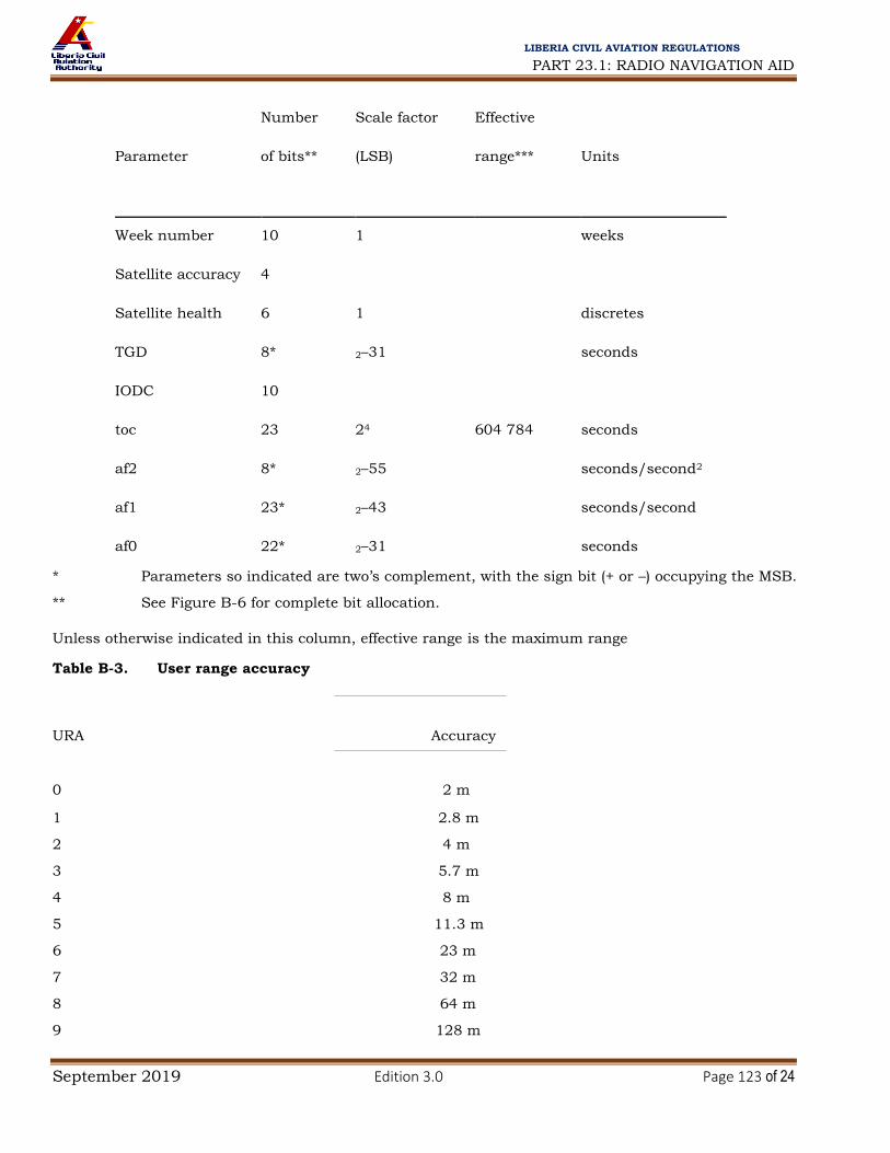
PART 23.1: RADIO NAVIGATION AID
September 2019 Edition 3.0 Page 123 of 24
LIBERIA CIVIL AVIATION REGULATIONS
Number Scale factor Effective
Parameter of bits** (LSB) range*** Units
Week number 10 1 weeks
Satellite accuracy 4
Satellite health 6 1 discretes
TGD 8* 2–31 seconds
IODC 10
24
toc 23 604 784 seconds
af2 8* 2–55 seconds/second2
af1 23* 2–43 seconds/second
af0 22* 2–31 seconds
* Parameters so indicated are two’s complement, with the sign bit (+ or –) occupying the MSB. ** See Figure B-6 for complete bit allocation.
Unless otherwise indicated in this column, effective range is the maximum range
Table B-3. User range accuracy
URA Accuracy
0 2 m 1 2.8 m 2 4 m 3 5.7 m 4 8 m 5 11.3 m 6 23 m 7 32 m 8 64 m 9 128 m

PART 23.1: RADIO NAVIGATION AID
September 2019 Edition 3.0 Page 124 of 24
LIBERIA CIVIL AVIATION REGULATIONS
10 256 m 11 512 m 12 1 024 m 13 2 048 m 14 4 096 m
15 Do not use
3.1.1.3.1.3 Health. The transmitting satellite 6-bit health indication shall be provided by bits 17 through 22 of word 3.
The MSB shall indicate a summary of the health of the navigation data, where:
a) 0 = all navigation data are valid; and
b) 1 = some of the navigation data are not valid.
The 5 LSBs shall indicate the health of the signal components in accordance with 3.1.1.3.3.4. The health indication shall be provided relative to the capabilities of each satellite as designated by the configuration code in 3.1.1.3.3.5. Any satellite that does not have a certain capability shall be indicated as “healthy” if the lack of this capability is inherent in its design or it has been configured into a mode which is normal from a receiver standpoint and does not require that capability. Additional health data shall be given in subframes 4 and 5.
Note.— The data given in subframe 1 may differ from that shown in subframes 4 and/or 5 of other satellites since the latter may be updated at a different time.
3.1.1.3.1.4 Issue of data, clock (IODC). Bits 23 and 24 of word 3 in subframe 1 shall be the 2 MSBs of the 10-bit IODC term. Bits 1 through 8 of word 8 in subframe 1 shall contain the 8 LSBs of the IODC. The IODC shall indicate the issue number of data set. The transmitted IODC shall be different from any value transmitted by the satellite during the preceding 7 days.
Note.— The relationship between the IODC and the Issue of Data, Ephemeris (IODE) terms is defined in 3.1.1.3.2.2.
3.1.1.3.1.5 Estimated group delay differential. Bits 17 through 24 of word 7 shall contain the correction term, TGD, to account for the effect of satellite group delay differential.
Note.— TGD does not include any C/A to P(Y) code relative group delay error.
3.1.1.3.1.6 Satellite clock correction parameters. Bits 9 through 24 of word 8, bits 1 through 24 of word 9, and bits 1 through 22 of word 10 shall contain the parameters needed by the users for apparent satellite clock correction (toc, af2, af1 and af0).
3.1.1.3.1.7 Reserved data fields. Reserved data fields shall be as indicated in Table B-4. All reserved data fields shall support valid parity within their respective words.

PART 23.1: RADIO NAVIGATION AID
September 2019 Edition 3.0 Page 125 of 24
LIBERIA CIVIL AVIATION REGULATIONS
3.1.1.3.2 Subframes 2 and 3 — satellite ephemeris data. Subframes 2 and 3 shall contain the ephemeris representation of the transmitting satellite.
3.1.1.3.2.1 Ephemeris parameters. The ephemeris parameters shall be as indicated in Table B-5. For each parameter in subframe 2 and 3, the number of bits, the scale factor of the LSB, the range, and the units shall be as specified in Table B-6.
3.1.1.3.2.2 Issue of data, ephemeris (IODE). The IODE shall be an 8-bit number equal to the 8 LSBs of the 10-
bit IODC of the same data set. The IODE shall be provided in both subframes 2 and 3 for the purpose of
comparison with the 8 LSBs of the IODC term in subframe 1. Whenever these three terms do not match,
as a result of a data set cutover, new data shall be collected. The transmitted IODE shall be different from any value transmitted by the satellite during the preceding six hours (Note 1). Any change in the
subframe 2 and 3 data shall be accomplished in concert with a change in both IODE words. Change to
new data sets shall occur only on hour boundaries except for the first data set of a new upload.
Additionally, the toe value, for at least the first data set transmitted by a satellite after an upload, shall
be different from that transmitted prior to the change (Note 2).
Table B-4. Subframe 1 reserved data fields
Word Bit
3 11–12
4 1–24
5 1–24
6 1–24
7 1–23
Table B-5. Ephemeris data
M0 Mean anomaly at reference time
n Mean motion difference from computed value
e Eccentricity
A
Square root of the semi-major axis
OMEGA0 Longitude of ascending node of orbit plane at weekly epoch
i0 Inclination angle at reference time
ω Argument of perigee

PART 23.1: RADIO NAVIGATION AID
September 2019 Edition 3.0 Page 126 of 24
LIBERIA CIVIL AVIATION REGULATIONS
OMEGADOT Rate of right ascension
iDOT Rate of inclination angle
Cuc
Amplitude of the cosine harmonic correction term to the argument of
latitude
Cus
Amplitude of the sine harmonic correction term to the argument of
latitude
Crc Amplitude of the cosine harmonic correction term to the orbit radius
Crs Amplitude of the sine harmonic correction term to the orbit radius
Cic Amplitude of the cosine harmonic correction term to the angle of inclination
Cis
Amplitude of the sine harmonic correction term to the angle of
inclination
toe Reference time, ephemeris
IODE Issue of data, ephemeris
Table B-6. Ephemeris parameters
Number Scale factor Effective
Parameter of bits** (LSB) range*** Units
IODE 8
2–5
Crs 23* metres
n 23* 2–43 semi-circles/second
M0 32* 2–31 semi-circles
Cuc 23* 2–29 radians
e 32 2–33 0.03 dimensionless
Cus 23* 2–29 radians
√
32 2–19
metres1/2
A
toe 23 24 604 784 seconds
Cic 23* 2–29 radians
OMEGA0 32* 2–31 semi-circles

PART 23.1: RADIO NAVIGATION AID
September 2019 Edition 3.0 Page 127 of 24
LIBERIA CIVIL AVIATION REGULATIONS
Cis 23* 2–29 radians
i0 32* 2–31 semi-circles
Crc 23* 2–5 metres
ω 32* 2–31 semi-circles
OMEGADOT 24* 2–43 semi-circles/second
iDOT 14* 2–43 semi-circles/second
* Parameters so indicated are two’s complement, with the sign bit (+ or –) occupying the MSB. ** See Figure B-6 for complete bit allocation in subframe. *** Unless otherwise indicated in this column, effective range is the maximum range attainable
with the indicated bit allocation and scale factor.
Note 1.— The IODE/IODC terms provide the receiver with a means for detecting any changes in the ephemeris/clock representation parameters.
Note 2.— The first data set may change (3.1.1.2.2) at any time during the hour and therefore may be transmitted by the satellite for less than 1 hour.
3.1.1.3.2.3 Reserved data fields. Within word 10, subframe 2, bits 17 through 22 shall be reserved. Reserved data fields shall support the valid parity within their respective words.
3.1.1.3.3 Subframes 4 and 5 — support data. Both subframes 4 and 5 shall be subcommutated 25 times each. With the possible exception of “reserved” pages and explicit repeats, each page shall contain different data in words 3 through 10. The pages of subframe 4 shall use 6 different formats, and the pages of subframe 5 shall use two different formats as indicated in Figure B-6.
Pages of subframe 4 shall be as follows:
a) Pages 2, 3, 4, 5, 7, 8, 9 and 10: almanac data for satellites 25 through 32 respectively. If the 6-bit health status word of page 25 is set to 6 “ones” (3.1.1.3.3.4) then the satellite ID of the page shall not have a value in the range of 25 through 32;
Note.— These pages may be designed for other functions. The format and content for each page is defined by the satellite ID of that page.
b) Page 17: special messages;
c) Page 18: ionospheric and UTC data;
d) Page 25: satellite configurations for 32 satellites; and

PART 23.1: RADIO NAVIGATION AID
September 2019 Edition 3.0 Page 128 of 24
LIBERIA CIVIL AVIATION REGULATIONS
e) Pages 1, 6, 11, 12, 13, 14, 15, 23, 19, 20, 21, 22, 23 and 24: reserved.
Pages of subframe 5 shall be as follows:
a) Pages 1 through 24: almanac data for satellite 1 through 24; and
b) Page 25: satellite health data for satellite 1 through 24, the almanac reference time and the almanac reference week number.
3.1.1.3.3.1 Data ID. The two MSBs of word 3 in each page shall contain the data ID that defines the applicable GPS navigation data structure. The data ID shall be as indicated in Table B-7 in accordance with the following:
a) for those pages which are assigned to contain the almanac data of one specific satellite, the data ID shall define the data structure utilized by that satellite whose almanac data are contained in that page;
b) for all other pages, the data ID shall denote the data structure of the transmitting satellite; and
c) data ID “1” (denoted by binary state 00) shall not be used.
3.1.1.3.3.2 Satellite ID. The satellite ID shall be provided by bits 3 through 8 of word 3 in each page. The satellite IDs shall be utilized two ways:
a) for those pages which contain the almanac data of a given satellite, the satellite ID shall be the same number that is assigned the PRN code phase of that satellite in accordance with Table B-1; and
b) for all other pages the satellite ID assigned in accordance with Table B-7 shall serve as the “page ID”. IDs 1 through 32 shall be assigned to those pages which contain the almanac data of specific satellites (pages 1 through 24 of subframe 5 and pages 2 through 5, and 7 through 10 of subframe 4). The “0” ID (binary all zeros) shall be assigned to indicate a dummy satellite, while IDs 51 through 63 shall be utilized for pages containing other than almanac data for a specific satellite (Notes 1 and 2).
Note 1.— Specific IDs are reserved for each page of subframes 4 and 5; however, the satellite ID of pages 2, 3, 4, 5, 7, 8, 9 and 10 of subframe 4 may change for each page to reflect the alternate contents for that page.
Note 2.— The remaining IDs (33 through 50) are unassigned.
Table B-7. Data IDs and satellite IDs in subframes 4 and 5
Subframe 4 Subframe 5
Page Data ID Satellite ID* Data ID Satellite ID*

PART 23.1: RADIO NAVIGATION AID
September 2019 Edition 3.0 Page 129 of 24
LIBERIA CIVIL AVIATION REGULATIONS
1 *** 57 ** 1
2**** ** 25 ** 2
3**** ** 26 ** 3
4**** ** 27 ** 4
5**** ** 28 ** 5
6 *** 57 ** 6
7**** ** 29 ** 7
8**** ** 30 ** 8
9**** ** 31 ** 9
10**** ** 32 ** 10
11 *** 57 ** 11
12 *** 62 ** 12
13 *** 52 ** 13
14 *** 53 ** 14
15 *** 54 ** 15
23 *** 57 ** 23
17 *** 55 ** 17
18 *** 56 ** 18
19 *** 58***** ** 19
20 *** 59***** ** 20
21 *** 57 ** 21
22 *** 60***** ** 22
23 *** 61***** ** 23
24 *** 62 ** 24
25 *** 63 *** 51
* “0” indicates “dummy” satellite. When using “0” to indicate a dummy satellite, the data ID of
the transmitting satellite is used.
** Data ID of that satellite whose satellite ID appears in that page. *** Data ID of transmitting satellite. **** Pages 2, 3, 4, 5, 7, 8, 9 and 10 of subframe 4 may contain almanac data for satellites 25
through 32, respectively, or data for other functions as identified by a different satellite ID from the value
shown. ***** Satellite ID may vary.
3.1.1.3.3.3 Almanac. Pages 1 through 24 of subframe 5, as well as pages 2 through 5 and 7 through 10 of
subframe 4 shall contain the almanac data and a satellite health status word (3.1.1.3.3.4) for up to 32
satellites. The almanac data shall be a reduced-precision subset of the clock and ephemeris parameters.

PART 23.1: RADIO NAVIGATION AID
September 2019 Edition 3.0 Page 130 of 24
LIBERIA CIVIL AVIATION REGULATIONS
The data shall occupy all bits of words 3 through 10 of each page except the 8 MSBs of word 3 (data ID
and satellite ID), bits 17 through 24 of word 5 (satellite health), and the 50 bits devoted to parity. The
number of bits, the scale factor (LSB), the range and the units of the almanac parameters shall be as
indicated in Table B-8. The almanac message for any dummy satellite shall contain alternating “ones” and
“zeros” with a valid parity.
3.1.1.3.3.3.1 Almanac reference time. The almanac reference time, toa, shall be a multiple of 212 seconds
occurring approximately 70 hours after the first valid transmission time for this almanac data set. The
almanac shall be updated often enough to ensure that GPS time, t, will differ from toa by less than 3.5
days during the transmission period. The almanac parameters shall be updated at least once every 6 days
during normal operations.
3.1.1.3.3.3.2 Almanac time parameters. The almanac time parameters shall consist of an 11-bit constant
term (af0) and an 11-bit first order term (af1).
3.1.1.3.3.3.3 Almanac reference week. Bits 17 through 24 of word 3 in page 25 of subframe 5 shall indicate
the number of the week (WNa) to which the almanac reference time (toa) is referenced. The WNa term shall
consist of the 8 LSBs of the full week number. Bits 9 through 23 of word 3 in page 25 of subframe 5 shall
contain the value of toa that is referenced to this WNa.
3.1.1.3.3.4 Health summary. Subframes 4 and 5 shall contain two types of satellite health data:
a) each of the 32 pages that contain the clock/ephemeris related almanac data shall provide an 8-bit
satellite health status word regarding the satellite whose almanac data they carry; and
b) the 25th pages of subframes 4 and 5 jointly shall contain 6-bit health data for up to 32 satellites.
3.1.1.3.3.4.1 The 8-bit health status words shall occupy bits 17 through 24 of word 5 in those 32 pages
that contain the almanac data for individual satellites. The 6-bit health status words shall occupy the 24
MSBs of words 4 through 9 in page 25 of subframe 5, and bits 19 through 24 of word 8, the 24 MSBs of
word 9, and the 18 MSBs of word 10 in page 25 of subframe 4.
Table B-8. Almanac parameters
Number Scale factor Effective
Parameter of bits** (LSB) range*** Units
e 23 2–21 dimensionless

PART 23.1: RADIO NAVIGATION AID
September 2019 Edition 3.0 Page 131 of 24
LIBERIA CIVIL AVIATION REGULATIONS
toa 8 212 602 112 seconds
δi**** 23* 2–19 semi-circles
OMEGADOT 23* 2–38 semi-circles/second
√
24* 2–11
metres1/2
A
OMEGA0 24* 2–23 semi-circles
ω 24* 2–23 semi-circles
M0 24* 2–23 semi-circles
af0 11* 2–20 seconds
af1 11* 2–38 seconds/second
* Parameters so indicated are two’s complement, with the sign bit (+ or –) occupying the MSB. ** See Figure B-6 for complete bit allocation in subframe. *** Unless otherwise indicated in this column, effective range is the maximum range attainable
with the indicated bit allocation and scale factor.
**** Relative to i0 = 0.30 semi-circles.
3.1.1.3.3.4.2 The 3 MSBs of the 8-bit health status words shall indicate health of the navigation data in
accordance with the code given in Table B-9. The 6-bit words shall provide a 1-bit summary of the
navigation data’s health status in the MSB position in accordance with 3.1.1.3.1.3. The 5 LSBs of both the
8-bit and the 6-bit health status words shall provide the health status of the satellite’s signal components
in accordance with the code given in Table B-10.
Table B-9. Navigation data health indication
Bit position in
page
137 138 139 Indication
0 0 0 ALL DATA OK
0 0 1 PARITY FAILURE — some or all parity bad
0 1 0 TLM/HOW FORMAT PROBLEM — any departure from standard format
(e.g. preamble misplaced and/or incorrect), except for incorrect Z-count, as
reported
in HOW
0 1 1 Z-COUNT in HOW BAD — any problem with Z-count value not reflecting

PART 23.1: RADIO NAVIGATION AID
September 2019 Edition 3.0 Page 132 of 24
LIBERIA CIVIL AVIATION REGULATIONS
actual code phase
1 0 0
SUBFRAMES 1, 2, 3 — one or more elements in words 3 through 10 of one
or
more subframes are bad
1 0 1 SUBFRAMES 4, 5 — one or more elements in words 3 through 10 of one or
more subframes are bad
1 1 0 ALL UPLOADED DATA BAD — one or more elements in words 3 through 10
of any one (or more) subframes are bad
1 1 1 ALL DATA BAD — TLM word and/or HOW and one or more elements in any
one (or more) subframes are bad
Table B-10. Codes for health of satellite signal components
MSB LSB Indication
0 0 0 0 0 ALL SIGNALS OK
1 1 1 0 0 SATELLITE IS TEMPORARILY OUT — do not use this satellite
during current pass ___
1 1 1 0 1
SATELLITE WILL BE TEMPORARILY OUT — use with caution
___
1 1 1 1 0 SPARE
1 1 1 1 1 MORE THAN ONE COMBINATION WOULD BE REQUIRED TO
DESCRIBE ANOMALIES, EXCEPT THOSE MARKED BY ___
All other
combinations SATELLITE EXPERIENCING CODE MODULATION AND/OR
SIGNAL POWER LEVEL TRANSMISSION PROBLEMS. The user
may experience intermittent tracking problems if satellite is acquired.
3.1.1.3.3.4.3 A special meaning shall be assigned, to the 6 “ones” combination of the 6-bit health status
words in the 25th pages of subframes 4 and 5; it shall indicate that “the satellite which has that ID is not
available and there may be no data regarding that satellite in the page of subframe 4 or 5 that is assigned
to normally contain the almanac data of that satellite”.
Note.— This special meaning applies to the 25th pages of subframes 4 and 5 only. There may be data
regarding another satellite in the almanac page referred to above as defined in 3.1.1.3.3.3.

PART 23.1: RADIO NAVIGATION AID
September 2019 Edition 3.0 Page 133 of 24
LIBERIA CIVIL AVIATION REGULATIONS
3.1.1.3.3.4.4 The health indication shall be provided relative to the capabilities of each satellite as
designated by the configuration code in 3.1.1.3.3.5. Accordingly, any satellite that does not have a certain
capability shall be indicated as “healthy” if the lack of this capability is inherent in its design or it has been
configured into a mode which is normal from a receiver standpoint and does not require that capability.
The predicted health data shall be updated at the time of upload.
Note 1.— The transmitted health data may not correspond to the actual health of the transmitting satellite or
other satellites in the constellation.
Note 2.— The data given in subframes 1, 4 and 5 of the other satellites may differ from that shown in subframes 4 and/or 5 since the latter may be updated at a different time.
3.1.1.3.3.5 Satellite configuration summary. Page 25 of subframe 4 shall contain a 4-bit-long term for each
of up to 32 satellites to indicate the configuration code of each satellite. These 4-bit terms shall occupy bits
9 through 24 of words 3, the 24 MSBs of words 4 through 7, and the 23 MSBs of word 8, all in page 25 of
subframe 4. The MSB of each 4-bit term shall indicate whether anti-spoofing is activated (MSB = 1) or not
activated (MSB = 0). The 3 LSBs shall indicate the configuration of each satellite using the following code:
Code Satellite configuration 1 Block II/IIA/IIR satellite 10 Block IIR-M satellite 11 Block IIF satellite
3.1.1.3.3.6 UTC parameters. Page 18 of subframe 4 shall include:
a) the parameters needed to relate GPS time to UTC time; and
b) notice to the user regarding the scheduled future or past (relative to navigation message upload)
value of the delta time due to leap seconds (tLSF), together with the week number (WNLSF) and the day
number (DN) at the end of which the leap second becomes effective. “Day one” shall be the first day relative
to the end/start of week and the WNLSF value consists of the 8 LSBs of the full week number. The absolute
value of the difference between the untruncated WN and WNLSF values shall not exceed 127.
Note.— The user is expected to account for the truncated nature of this parameter as well as truncation of
WN, WNt and WNLSF due to rollover of the full week number (3.1.1.2.6.2).
3.1.1.3.3.6.1 The 24 MSBs of words 6 through 9, and the 8 MSBs of word 10 in page 18 of subframe 4
shall contain the parameters related to correlating UTC time with GPS time. The bit length, scale factors,
ranges, and units of these parameters shall be as specified in Table B-11.
3.1.1.3.3.7 Ionospheric parameters. The ionospheric parameters that allow the GPS SPS user to utilize the
ionospheric model for computation of the ionospheric delay shall be contained in page 18 of subframe 4 as
specified in Table B-12.
3.1.1.3.3.8 Special message. Page 17 of subframe 4 shall be reserved for special messages.
Table B-11. UTC parameters

PART 23.1: RADIO NAVIGATION AID
September 2019 Edition 3.0 Page 134 of 24
LIBERIA CIVIL AVIATION REGULATIONS
Number Scale factor Effective
Parameter of bits** (LSB) range*** Units
Ao 32* 2–30 seconds
A1 24* 2–50 seconds/second
tLS 8* 1 seconds
tot 8 212 602 112 seconds
WNt 8 1 weeks
WNLSF 8 1 weeks
DN 8**** 1 7 days
tLSF 8* 1 seconds
* Parameters so indicated are two’s complement, with the sign bit (+ or –) occupying the MSB. ** See Figure B-6 for complete bit allocation in subframe. *** Unless otherwise indicated in this column, effective range is the maximum range attainable
with the indicated bit allocation and scale factor. **** Right justified.
Table B-12. Ionospheric parameters
Number Scale factor Effective
Parameter of bits** (LSB) range*** Units
α0 8* 2–30 seconds
α1 8* 2–27 seconds/semi-circle
α2 8* 2–24 seconds/semi-circle2
α3 8* 2–24 seconds/semi-circle3
β0 8* 211 seconds
β1 8* 214 seconds/semi-circle
β2 8* 223 seconds/semi-circle2
β3 8* 223 seconds/semi-circle3
* Parameters so indicated are two’s complement, with the sign bit (+ or –) occupying the MSB. ** See Figure B-6 for complete bit allocation in subframe. *** Unless otherwise indicated in this column, effective range is the maximum range attainable
with the indicated bit allocation and scale factor.

PART 23.1: RADIO NAVIGATION AID
September 2019 Edition 3.0 Page 135 of 24
LIBERIA CIVIL AVIATION REGULATIONS
3.1.1.3.3.9 Reserved data fields. All bits of words 3 through 10, except the 58 bits used for data ID, satellite
(page) ID, parity (six LSBs of each word) and parity computation (bits 23 and 24 of word 10) of pages 1, 6,
11, 12, 13, 14, 15, 23, 19, 20, 21, 22, 23 and 24 of subframe 4, and those almanac pages assigned
satellite ID of zero shall be designated as reserved. Other reserved bits in subframes 4 and 5 shall be as shown in Table B-13. Reserved bit positions of each word shall contain a pattern of alternating ones and
zeros with a valid word parity.
3.1.2 DEFINITIONS OF PROTOCOLS FOR DATA APPLICATION
Note.— This section defines the inter-relationships of the data broadcast message parameters. It provides
definitions of parameters that are not transmitted, but are used by either or both non-aircraft and aircraft
elements, and that define terms applied to determine the navigation solution and its integrity.
Table B-13. Reserved bits in subframes 4 and 5
Subframe Pages Words Reserved bit position in word
4 17 10 17 – 22
4 18 10 9 – 22
4 25 8 17 – 18
4 25 10 19 – 22
5 25 10 4 – 22
Table B-14. Parity encoding algorithms
D1 = d1 ⊕ D* 30
D2 = d2 ⊕ D* 30
D3 = d3 ⊕ D* 30
• •
• •
• •
• •
D24 = d24 ⊕ D*30
D25 = D*29 ⊕ d1 ⊕ d2 ⊕ d3 ⊕ d5 ⊕ d6 ⊕ d10 ⊕ d11 ⊕ d12 ⊕ d13 ⊕ d14 ⊕ d17 ⊕ d18 ⊕ d20 ⊕ d23
D26 = D*30 ⊕ d2 ⊕ d3 ⊕ d4 ⊕ d6 ⊕ d7 ⊕ d11 ⊕ d12 ⊕ d13 ⊕ d14 ⊕ d15 ⊕ d18 ⊕ d19 ⊕ d21 ⊕ d24
D27 = D*29 ⊕ d1 ⊕ d3 ⊕ d4 ⊕ d5 ⊕ d7 ⊕ d8 ⊕ d12 ⊕ d13 ⊕ d14 ⊕ d15 ⊕ d23 ⊕ d19 ⊕ d20 ⊕ d22
D28 = D*30 ⊕ d2 ⊕ d4 ⊕ d5 ⊕ d6 ⊕ d8 ⊕ d9 ⊕ d13 ⊕ d14 ⊕ d15 ⊕ d23 ⊕ d17 ⊕ d20 ⊕ d21 ⊕ d23
D29
= D*30 ⊕ d1 ⊕ d3 ⊕ d5 ⊕ d6 ⊕ d7 ⊕ d9 ⊕ d10 ⊕ d14 ⊕ d15 ⊕ d23 ⊕ d17 ⊕ d18 ⊕ d21 ⊕ d22 ⊕
d24

PART 23.1: RADIO NAVIGATION AID
September 2019 Edition 3.0 Page 136 of 24
LIBERIA CIVIL AVIATION REGULATIONS
D30 = D*29 ⊕ d3 ⊕ d5 ⊕ d6 ⊕ d8 ⊕ d9 ⊕ d10 ⊕ d11 ⊕ d13 ⊕ d15 ⊕ d19 ⊕ d22 ⊕ d23 ⊕ d24
where:
D1, D2, D3,... D29, D30 are the bits transmitted by the satellite;
D25, ... D30 are the computed parity bits;
d1, d2, ... d24 are the source data bits;
⊕ is the Modulo-2 or “Exclusive-Or” operation; and
* is used to identify the last two bits of the previous word of the subframe.
3.1.2.1 Parity algorithm. GPS parity algorithms are defined as indicated in Table B-14.
3.1.2.2 Satellite clock correction parameters. GPS system time t is defined as:
t = tsv – (Δtsv)L1
where
t = GPS system time (corrected for beginning and end-of-week crossovers);
tsv = satellite time at transmission of the message;
( tsv)L1= the satellite PRN code phase offset;
( tsv)L1= af0 + af1(t – toc) + af2(t – toc)2 + tr – TGD
where
af0, af1 and af2 and toc, are contained in subframe 1; and tr = the relativistic correction term (seconds)
tr = Fe √A sin Ek where
e and A are contained in subframes 2 and 3; Ek is defined in Table B-15; and
F =
–2 (µ)½ = –4.442807633(10)–10
s/m½
c2
where
µ = WGS-84 universal gravitational parameter (3.986005 × 10¹⁴ m3/s2)
c = the speed of light in a vacuum (2.99792458 × 10⁸ m/s)
Note.— The value of t is intended to account for the beginning or end-of-week crossovers. That is, if the
quantity t-toc is greater than 302 400 seconds, subtract 604 800 seconds from t. If the quantity t-toc is less
than –302 400 seconds, add 604 800 seconds to t.
3.1.2.3 Satellite position. The current satellite position (Xk, Yk, Zk) is defined as shown in Table B-15.
3.1.2.4 Ionospheric correction. The ionospheric correction (Tiono) is defined as:
,|x| 1,57

PART 23.1: RADIO NAVIGATION AID
September 2019 Edition 3.0 Page 137 of 24
LIBERIA CIVIL AVIATION REGULATIONS
seconds
|x| 1,57
Where,
3
αn
n
AMP 0
AMP n 0
m, seconds
si AMP 0, AMP 0
x
2π t‐50 400) , (radians)
PER
3 0
βn
n PER 72 000 seconds
PER n m,
si PER 72 000, PER 72 000
F = 1.0 + 16.0[0.53 – E]3
αn and βn are the satellite transmitted data words with n = 0, 1, 2 and 3
b) Receiver generated terms
F 5,0 10–9 AMP 1– x2 x4
24
Tiono
2
10–9
F 5,0

PART 23.1: RADIO NAVIGATION AID
September 2019 Edition 3.0 Page 138 of 24
LIBERIA CIVIL AVIATION REGULATIONS
E = elevation angle between the user and satellite (semi-circles)
A
= azimuth angle between the user and satellite, measured clockwise positive from the
true North
φu
(semi-circles)
= user geodetic latitude (semi-circles) WGS-84
λu = user geodetic longitude (semi-circles) WGS-84
GPS time = receiver computed system time
c) Computed terms
x = phase (radians)
F = obliquity factor (dimensionless)
t = local time (seconds)
φm
= geomagnetic latitude of the earth projection of the ionospheric intersection point (mean
ionospheric
height assumed 350 km) (semi-circles)
λi = geomagnetic longitude of the earth projection of the ionospheric intersection point (semi-
circles)
φi
= geomagnetic latitude of the earth projection of the ionospheric intersection point (semi-
circles)
= earth’s central angle between user position and earth projection of ionospheric intersection point (semi-circles).

PART 23.1: RADIO NAVIGATION AID
September 2019 Edition 3.0 Page 139 of 24
LIBERIA CIVIL AVIATION REGULATIONS
Table B-15. Elements of coordinate systems
3.1.3
AIRCRAFT ELEMENTS
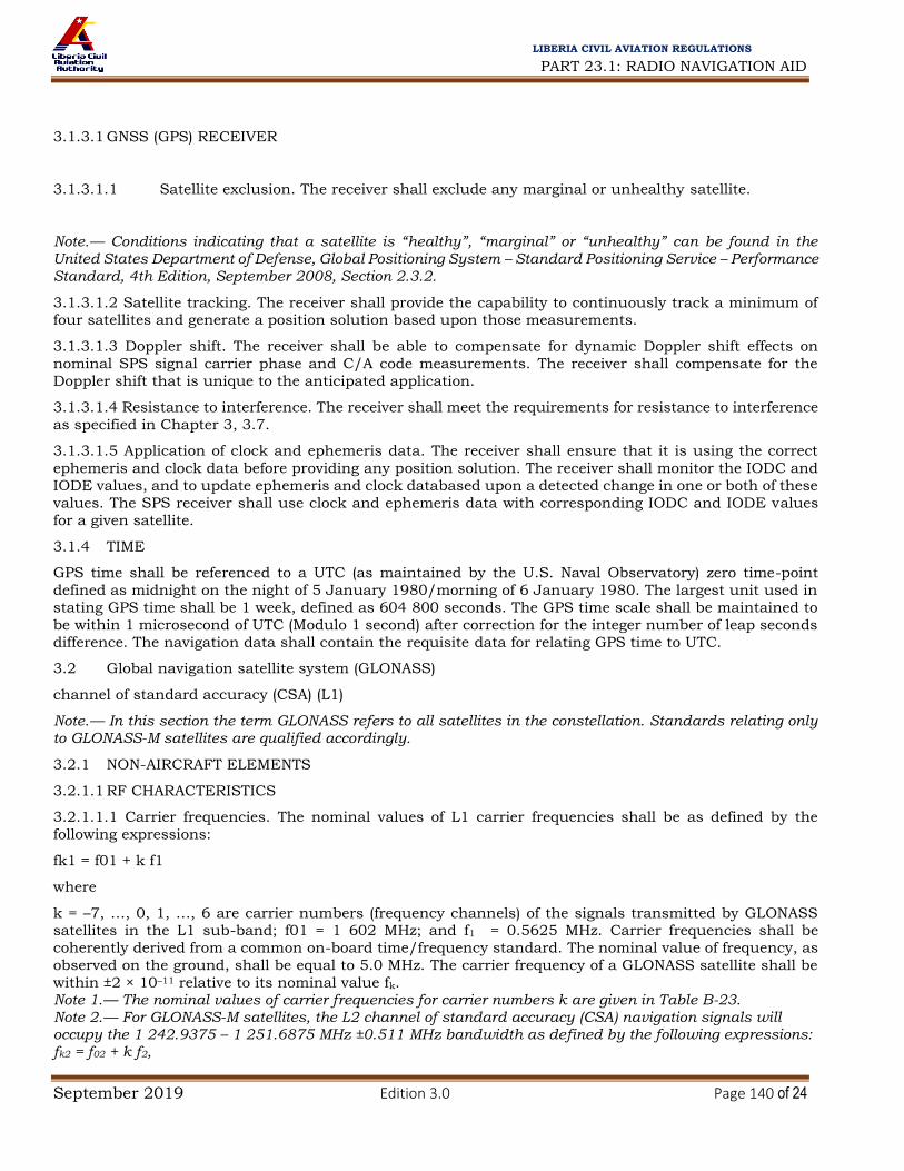
PART 23.1: RADIO NAVIGATION AID
September 2019 Edition 3.0 Page 140 of 24
LIBERIA CIVIL AVIATION REGULATIONS
3.1.3.1 GNSS (GPS) RECEIVER
3.1.3.1.1 Satellite exclusion. The receiver shall exclude any marginal or unhealthy satellite.
Note.— Conditions indicating that a satellite is “healthy”, “marginal” or “unhealthy” can be found in the United States Department of Defense, Global Positioning System – Standard Positioning Service – Performance Standard, 4th Edition, September 2008, Section 2.3.2.
3.1.3.1.2 Satellite tracking. The receiver shall provide the capability to continuously track a minimum of four satellites and generate a position solution based upon those measurements.
3.1.3.1.3 Doppler shift. The receiver shall be able to compensate for dynamic Doppler shift effects on
nominal SPS signal carrier phase and C/A code measurements. The receiver shall compensate for the
Doppler shift that is unique to the anticipated application.
3.1.3.1.4 Resistance to interference. The receiver shall meet the requirements for resistance to interference
as specified in Chapter 3, 3.7.
3.1.3.1.5 Application of clock and ephemeris data. The receiver shall ensure that it is using the correct
ephemeris and clock data before providing any position solution. The receiver shall monitor the IODC and
IODE values, and to update ephemeris and clock databased upon a detected change in one or both of these
values. The SPS receiver shall use clock and ephemeris data with corresponding IODC and IODE values
for a given satellite.
3.1.4 TIME
GPS time shall be referenced to a UTC (as maintained by the U.S. Naval Observatory) zero time-point
defined as midnight on the night of 5 January 1980/morning of 6 January 1980. The largest unit used in
stating GPS time shall be 1 week, defined as 604 800 seconds. The GPS time scale shall be maintained to
be within 1 microsecond of UTC (Modulo 1 second) after correction for the integer number of leap seconds
difference. The navigation data shall contain the requisite data for relating GPS time to UTC.
3.2 Global navigation satellite system (GLONASS)
channel of standard accuracy (CSA) (L1)
Note.— In this section the term GLONASS refers to all satellites in the constellation. Standards relating only to GLONASS-M satellites are qualified accordingly.
3.2.1 NON-AIRCRAFT ELEMENTS
3.2.1.1 RF CHARACTERISTICS
3.2.1.1.1 Carrier frequencies. The nominal values of L1 carrier frequencies shall be as defined by the
following expressions:
fk1 = f01 + k f1
where
k = –7, …, 0, 1, …, 6 are carrier numbers (frequency channels) of the signals transmitted by GLONASS satellites in the L1 sub-band; f01 = 1 602 MHz; and f1 = 0.5625 MHz. Carrier frequencies shall be
coherently derived from a common on-board time/frequency standard. The nominal value of frequency, as
observed on the ground, shall be equal to 5.0 MHz. The carrier frequency of a GLONASS satellite shall be
within ±2 × 10–11 relative to its nominal value fk. Note 1.— The nominal values of carrier frequencies for carrier numbers k are given in Table B-23. Note 2.— For GLONASS-M satellites, the L2 channel of standard accuracy (CSA) navigation signals will occupy the 1 242.9375 – 1 251.6875 MHz ±0.511 MHz bandwidth as defined by the following expressions: fk2 = f02 + k f2,

PART 23.1: RADIO NAVIGATION AID
September 2019 Edition 3.0 Page 141 of 24
LIBERIA CIVIL AVIATION REGULATIONS
f02 = 1 246 MHz; f2 = 0.4375 MHz.
For any given value of k the ratio of carrier frequencies of L1 and L2 sub-bands will be equal to: _ 7 9
Table B-16. L1 carrier frequencies
HAn
Nominal value of
Carrier number
frequency in L1 sub-band
(see 3.2.1.3.4) (MHz)
06 6 1 605.3750
05 5 1 604.8125
4 4 1 604.2500
3 3 1 603.6875
2 2 1 603.1250
1 1 1 602.5625
0 0 1 602.0000
–1 31 1 601.4375
–2 30 1 600.8750
–3 29 1 600.3125
–4 28 1 599.7500
–5 27 1 599.1875
–6 26 1 598.6250
–7 25 1 598.0625
3.2.1.1.2 Carrier phase noise. The phase noise spectral density of the unmodulated carrier shall be such
that a phase locked loop of 10 Hz one-sided noise bandwidth provides the accuracy of carrier phase tracking
not worse than 0.1 radian (1 sigma).
3.2.1.1.3 GLONASS pseudo-random code generation. The pseudo-random ranging code shall be a 511-bit
sequence that is sampled at the output of the seventh stage of a 9-stage shift register. The initialisation
vector to generate this sequence shall be “111111111”. The generating polynomial that corresponds to the
9-stage shift register shall be:
G(x) = 1 + x5 + x9.

PART 23.1: RADIO NAVIGATION AID
September 2019 Edition 3.0 Page 142 of 24
LIBERIA CIVIL AVIATION REGULATIONS
3.2.1.1.4 Spurious emissions. The power of the transmitted RF signal beyond the GLONASS allocated
bandwidth shall not be more than –40 dB relative to the power of the unmodulated carrier.
Note 1.— GLONASS satellites launched during 1998 to 2005 and beyond use filters limiting out-of-band emissions to the harmful interference limit contained in Recommendation ITU-R RA.769 for the 1 660 – 1
670 MHz band.
Note 2.— GLONASS satellites launched beyond 2005 use filters limiting out-of-band emissions to the
harmful interference limit contained in Recommendation ITU-R RA.769 for the 1 610.6 – 1 613.8 MHz and 1 660 – 1 670 MHz bands.
3.2.1.1.5 Correlation loss. The loss in the recovered signal power due to imperfections in the signal
modulation and waveform distortion shall not exceed 0.8 dB.
Note.— The loss in signal power is the difference between the broadcast power in a 1.022 MHz bandwidth and the signal power recovered by a noise-free, loss-free receiver with 1-chip correlator spacing and a 1.022
MHz bandwidth.
3.2.1.2 DATA STRUCTURE
3.2.1.2.1 General. The navigation message shall be transmitted as a pattern of digital data which are coded by Hamming code and transformed into relative code. Structurally, the data pattern shall be generated as
continuously repeating superframes. The superframe shall consist of the frames and the frames shall
consist of the strings. The boundaries of strings, frames and superframes of navigation messages from
different GLONASS satellites shall be synchronized within 2 milliseconds.
3.2.1.2.2 Superframe structure. The superframe shall have a 2.5-minute duration and shall consist of 5
frames. Within each superframe a total content of non-immediate information (almanac for 24 GLONASS
satellites) shall be transmitted.
Note.— Superframe structure with indication of frame numbers in the superframe and string numbers in
the frames is shown in Figure B-7.
3.2.1.2.3 Frame structure. Each frame shall have a 30-second duration and shall consist of 15 strings.
Within each frame the total content of immediate information (ephemeris and time parameters) for given
satellite and a part of non-immediate information (almanac) shall be transmitted. The frames 1 through 4
shall contain the part of almanac for 20 satellites (5 satellites per frame) and frame 5 shall contain the remainder of almanac for 4 satellites. The almanac for one satellite shall occupy two strings.
Note.— Frame structures are shown in Figures B-8 and B-9.
3.2.1.2.4 String structure. Each string shall have a 2-second duration and shall contain binary chips of
data and time mark. During the last 0.3 second within this 2-second interval (at the end of each string)

PART 23.1: RADIO NAVIGATION AID
September 2019 Edition 3.0 Page 143 of 24
LIBERIA CIVIL AVIATION REGULATIONS
the time mark shall be transmitted. The time mark (shortened pseudo-random sequence) shall consist of
30 chips with a time duration for each chip of 10 milliseconds and having the following sequence:
111110001101110101000010010110.
During the first 1.7 seconds within this 2-second interval (in the beginning of each string) 85 bits of data (each data bit of a 20 milliseconds duration) shall be transmitted in bi-binary format. The numbers of bits
in the string shall be increased from right to left. Along with information bits (bit positions 9 through 84)
the check bits of Hamming code (KX) (bit positions 1 through 8) shall be transmitted. The Hamming code
shall have a code length of 4. The data of one string shall be separated from the data of adjacent strings
by time mark (MB). The words of the data shall be registered by MSB ahead. In each string bit position, 85 shall be an idle chip (“0”) and be transmitted first.
3.2.1.2.4.1 Strings 1 through 4. The information contained in strings 1 through 4 of each frame shall
correspond to the satellite from which it is transmitted. This information shall not be changed within the
superframe.
3.2.1.2.4.2 Strings 5 through 15. Strings 5 through 15 of each frame shall contain GLONASS almanac for 4 or 5 satellites. The information contained in the fifth string shall be repeated in each frame of the
superframe.
Note.— String structure is given in Figure B-10.
3.2.1.3 DATA CONTENT
3.2.1.3.1 Ephemeris and time parameters. The ephemeris and time parameters shall be as follows:
m = the string number within the frame;
tk = the time referenced to the beginning of the frame within the current day. It is calculated
according to the satellite time scale. The integer number of hours elapsed since the beginning of the current
day is registered in the 5 MSBs. The integer number of minutes elapsed since the beginning of the current
hour is registered in the next 6 bits. The number of 30-second intervals elapsed since the beginning of the
current minute is registered in the one LSB. The beginning of the day according to the satellite time scale coincides with the beginning of the recurrent superframe;
tb = the time interval within the current day according to UTC(SU) + 03 hours 00 min. The
immediate data transmitted within the frame are referred to the middle of tb. Duration of the time interval
and therefore the maximum value of tb depends on the value of the flag P1;
γn(tb) = the relative deviation of predicted carrier frequency value of n-satellite from the nominal
value at the instant tb, i.e.
γn tb
fn tb –
fHn
,
fHn
where
fn(tb) = the forecast frequency of n-satellite clocks at an instant tb;
fhn = the nominal value of frequency of n-satellite clocks;
τn(tb) = the correction to the n-satellite time tn relative to GLONASS time tc at an instant tb, i.e. τn(tb) = tc(tb) –
tn(tb);
xn(tb), yn(tb), zn(tb) = the coordinates of n-satellite in PZ-90 coordinate system at an instant tb;
x n tb , y n tb , z n tb = the velocity vector components of n-satellite in PZ-90 coordinate system at an instant tb;

PART 23.1: RADIO NAVIGATION AID
September 2019 Edition 3.0 Page 144 of 24
LIBERIA CIVIL AVIATION REGULATIONS
x n tb , y n tb , z n tb = the acceleration components of n-satellite in PZ-90 coordinate system at an instant tb, which are caused
by effect of sun and moon;
En = an indication of the “age” of the immediate information, i.e. a time interval elapsed since
the instant of its calculation (uploading) until the instant tb for n-satellite;
Bn = the health flag. Values greater than 3 indicate the fact of malfunction of given satellite;
P1 = a flag indicating the time interval between the current and previous value of the tb
parameters in minutes as shown:
P1 Time interval between adjacent values of tb in minutes
0 0
1 30
10 45
11 60
P2 = a flag indicating whether the value of tb is odd or even. A value of “1” indicates a 30-minute
interval of service information transmit (tb = 1, 3, 5 …), a value of “0” indicates a 60-minute interval of
service information transmit (tb = 2, 6, 10 …);
P3 = a flag indicating the number of satellites for which an almanac is transmitted within a given
frame. “1” corresponds to 5 satellites and “0” corresponds to 4 satellites; and
Δτn = the time difference between the navigation RF signal transmitted in L2 sub-band and navigation
RF signal transmitted in L1 sub-band by given satellite:
Δτn = tf2 – tf1
Where tf1, tf2 are the equipment delays in L1 and L2 sub-bands respectively, expressed in units of time.
3.2.1.3.2 Ephemeris and time parameters. The ephemeris and time parameters shall be as indicated in
Table B-17. For the words for which numeric values may be positive or negative, the MSB shall be the sign
bit. The chip “0” shall correspond to the “+” sign and the chip “1” shall correspond to the “–” sign.
3.2.1.3.3 Arrangement of the ephemeris and time parameters. Arrangements of the ephemeris and time
parameters within a frame shall be as indicated in Table B-18.
3.2.1.3.4 Almanac parameters. The almanac parameters shall be as follows:
A = an index showing relation of this parameter with the almanac;
MAn = an index of the modification of nA-satellite: “00” indicates GLONASS satellite, and “01” indicates
GLONASS-M satellite;
τc
= the GLONASS time scale correction to UTC (SU) time. The correction τc is given at the instant
of day NA;
NA = the calendar day number within the 4-year period beginning since the leap year. The correction τc and
other almanac data (almanac of orbits and almanac of phases) relate to this day number;
nA = the slot number occupied by n-satellite;

PART 23.1: RADIO NAVIGATION AID
September 2019 Edition 3.0 Page 145 of 24
LIBERIA CIVIL AVIATION REGULATIONS
HAn = the channel number of a carrier frequency of nA-satellite (Table B-23);
λAn
= the longitude of the first (within the NA-day) ascending node of nA-satellite orbit in PZ-90
coordinate system;
tλ nA = the time of the first ascending node passage of nA -satellite within NA-day;
Table B-17. Ephemeris and time parameters
Number Scale factor Effective
Parameter of bits (LSB) range Units
m 4 1 dimensionless
5 1 0 to 23 hours
tk 6 1 0 to 59 minutes
1 30 0 or 30 seconds
tb 7 15 15...1 425 minutes
γn(tb) 11 2–40 ±2–30 dimensionless
τn(tb) 22 2–30 ±2–9
seconds
xn(tb), yn(tb), zn(tb) 27 2–11 ±2.7 × 10⁴ km
x˙n (tb), y˙n (tb), z˙n (tb) 24 2–20 ±4.3 km/second
x¨n (tb), y¨n (tb), z¨n (tb) 5 2–30 ±6.2 × 10⁻⁹
km/second2
En 5 1 0 to 31 days
Bn 3 1 0 to 7 dimensionless
P1 2 as detailed in 3.2.1.3.1
P2 1 1 0; 1 dimensionless
P3 1 1 0; 1 dimensionless
Δτn 5 2–30 ±13.97 × 10⁻⁹
seconds
Table B-18. Arrangements of the ephemeris and time parameters within the frame
Number String number Bit number
Parameter of bits within the frame within the frame
m 4 1...15 81–84
tk 12 1 65–76
tb 7 2 70–76
γn(tb) 11 3 69–79
τn(tb) 22 4 59–80
xn(tb) 27 1 9–35
yn(tb) 27 2 9–35
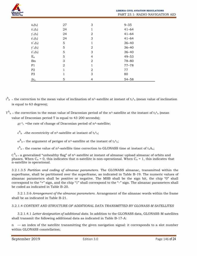
PART 23.1: RADIO NAVIGATION AID
September 2019 Edition 3.0 Page 146 of 24
LIBERIA CIVIL AVIATION REGULATIONS
zn(tb) 27 3 9–35
x˙n(tb) 24 1 41–64
y˙n(tb) 24 2 41–64
z˙n(tb) 24 3 41–64
x¨n(tb) 5 1 36–40
y¨n(tb) 5 2 36–40
z¨n(tb) 5 3 36–40
En 5 4 49–53
Bn 3 2 78–80
P1 2 1 77–78
P2 1 2 77
P3 1 3 80
Δτn 5 4 54–58
iA
n = the correction to the mean value of inclination of nA-satellite at instant of tλA
n (mean value of inclination
is equal to 63 degrees);
TA
n = the correction to the mean value of Draconian period of the nA-satellite at the instant of tλA
n (mean
value of Draconian period T is equal to 43 200 seconds);
ΔT˙An =the rate of change of Draconian period of nA-satellite;
εA
n =the eccentricity of nA-satellite at instant of tλA
n;
ωA
n = the argument of perigee of nA-satellite at the instant of tλA
n;
τA
n = the coarse value of nA-satellite time correction to GLONASS time at instant of tλAn;
CA
n = a generalized “unhealthy flag” of nA-satellite at instant of almanac upload almanac of orbits and phases. When Cn = 0, this indicates that n-satellite is non-operational. When Cn = 1, this indicates that n-satellite is operational.
3.2.1.3.5 Partition and coding of almanac parameters. The GLONASS almanac, transmitted within the
superframe, shall be partitioned over the superframe, as indicated in Table B-19. The numeric values of
almanac parameters shall be positive or negative. The MSB shall be the sign bit, the chip “0” shall
correspond to the “+” sign, and the chip “1” shall correspond to the “–” sign. The almanac parameters shall
be coded as indicated in Table B-20.
3.2.1.3.6 Arrangement of the almanac parameters. Arrangement of the almanac words within the frame
shall be as indicated in Table B-21.
3.2.1.4 CONTENT AND STRUCTURE OF ADDITIONAL DATA TRANSMITTED BY GLONASS-M SATELLITES
3.2.1.4.1 Letter designation of additional data. In addition to the GLONASS data, GLONASS-M satellites
shall transmit the following additional data as indicated in Table B-17-A: n — an index of the satellite transmitting the given navigation signal: it corresponds to a slot number
within GLONASS constellation;

PART 23.1: RADIO NAVIGATION AID
September 2019 Edition 3.0 Page 147 of 24
LIBERIA CIVIL AVIATION REGULATIONS
ln —
health flag for n-th satellite: “0” indicates the n-th satellite is healthy, “1” indicates the malfunction
of the n-th
satellite;
B1 — coefficient to determine UT1: it is equal to the difference between UT1 and UTC at the beginning of the day (NA),
expressed in seconds;
B2 — coefficient to determine
UT1: it is equal to the daily change of the difference UT1 (expressed in
seconds for a
mean sun day). These coefficients shall be used to transform between UTC(SU) and UT1:
UT1= UTC(SU) – UT1, where UT1 — Universal Time referenced to the Mean Greenwich Meridian (taking account of Pole motion),
UTC(SU) — Coordinated Universal Time of the Russian Federation State Standard,
UT1= B1 + B2 × (NT – NA),
KP — notification of a forthcoming leap second correction of UTC (±1 s) as shown:
KP UTC second correction data 00 No UTC correction at the end of the current quarter 1 UTC correction by plus 1 s at the end of the current quarter 11 UTC correction by minus 1 s at the end of the current quarter
Note.— GLONASS system timescale correction is usually performed once a year at midnight 00 hours 00 minutes 00 seconds in accordance with the early notification of the International Time Bureau (BIH/BIPM) at the end of a quarter: from 31 December to 1 January — first quarter, from 31 March to 1 April — second quarter, from 30 June to 1 July — third quarter, from 30 September to 1 October — fourth quarter
NT — current date, calendar number of the day within the four-year interval starting from 1 January in
a leap year;
Note.— An example of NT transformation into the common form of current data information (dd/mm/yy)
is presented in Attachment D, 4.2.7.1. N4 — four-year interval number starting from 1996;
FT — a parameter that provides the predicted satellite user range accuracy at time tb. Coding is as indicated
in Table B-17-B; M — type of satellite transmitting the navigation signal. 00 refers to a GLONASS satellite; 01 refers to a
GLONASS-M satellite;
P4 — flag to show that updated ephemeris parameters are present. “1” indicates that an updated ephemeris or
frequency/time parameters have been uploaded by the control segment;
Note.— Updated ephemeris or frequency/time information is transmitted in the next interval after the end of the current interval tb.

PART 23.1: RADIO NAVIGATION AID
September 2019 Edition 3.0 Page 148 of 24
LIBERIA CIVIL AVIATION REGULATIONS
P — technological parameter of control segment indicating the satellite operation mode in respect of
time parameters: 00 — τc parameter relayed from control segment, τGPS parameter relayed from control
segment; 01 — τc parameter relayed from control segment, τGPS parameter calculated on-board the GLONASS-M
satellite; 10 — τc parameter calculated on-board the GLONASS-M satellite; τGPS parameter relayed from
control segment; 11 — τc parameter calculated on-board the GLONASS-M satellite; τGPS parameter calculated on-
board the GLONASS-M satellite; τGPS — correction to GPS time relative to GLONASS time:
TGPS – TGL = T + τGPS, where T is the integer part, and τGPS is the fractional part of the difference between the system timescales
expressed in seconds.
Note.— The integer part T is determined from the GPS navigation message by the user receiver. MA
n — type of satellite nA: coding “00” indicates a GLONASS satellite, coding “01” indicates a GLONASS-
M satellite. 3.2.1.4.2 Additional data parameters. Additional data parameters are defined in Tables B-17-A to B-
18-A. 3.2.1.4.3 Location of additional data words within GLONASS-M navigation message. The required
location of additional data words within the GLONASS-M navigation message is defined in Table B-18-A.
Table B-17-A. Additional data parameters
Parameter No. of bits Scale factor (LSB) Effective range Units
n 5 1 0 to 31 Dimensionless ln 1 1 0; 1 Dimensionless B1 11 2–10 ±0.9 seconds
B2 10 2–16 (–4.5 to 3.5) × 10–3 s/mean sun day
KP 2 1 0 to 3 Dimensionless
NT 11 1 0 to 1 461 days
N4 5 1 1 to 31 four-year interval
FT 4 See table B-17-B
M 2 1 0 to 3 Dimensionless
P4 1 1 0; 1 Dimensionless P 2 1 00,01,10,11 Dimensionless
τGPS 22 2–30 ±1.9 × 10⁻³ seconds
MAn 2 1 0 to 3 Dimensionless

PART 23.1: RADIO NAVIGATION AID
September 2019 Edition 3.0 Page 149 of 24
LIBERIA CIVIL AVIATION REGULATIONS
Table B-17-B. FT word coding
FT value Pseudorange accuracy, 1 sigma (m)
0 1
1 2
2 2.5
3 4
4 5
5 7
6 10
7 12
8 14
9 16
10 32
11 64
12 128
13 256
14 512
15 Not used
Table B-18-A. Location of additional data words within the GLONASS-M navigation
message
String number within the Word Number of bits superframe Bit number within the string
n 5 4, 19, 34, 49, 64 11 – 15
ln 1 5, 7, 9, 11, 13, 15, 20, 9
22, 24, 26, 28, 30, 35,
37, 39, 41, 43, 45, 50,
52, 54, 56, 58, 60,
65, 67, 69, 71, 73, 75
3, 18, 33, 48, 63 65
B1 11 74 (within the superframe) 70–80
B2 10 74 (within the superframe) 60–69
KP 2 74 (within the superframe) 58–59
NT 11 4, 19, 34, 49, 64 16 – 26
N4 5 5, 20, 35, 50, 65 32 – 36
FT 4 4, 19, 34, 49, 64 30 – 33
M 2 4, 19, 34, 49, 64 9–10
P4 1 4, 19, 34, 49, 64 34
P 2 3, 18, 33, 48, 63 66–67
ιGPS 22 5, 20, 35, 50, 65 10 – 31
MA
n 2 6, 8, 10, 12, 14 78–79
Table B-19. Almanac partition within the superframe
Frame number Satellite numbers, for which almanac is within the superframe transmitted within given frame

PART 23.1: RADIO NAVIGATION AID
September 2019 Edition 3.0 Page 150 of 24
LIBERIA CIVIL AVIATION REGULATIONS
Table B-20. Almanac parameters coding
Number Scale factor Parameter of bits (LSB) Effective range Units
MAn 2 1 0 to 3 dimensionless
τc 28 2–27 ±1 seconds
NA 11 1 1 to 1 461 days
nA 5 1 1 to 24 dimensionless
HAn 5 1 0 to 31 dimensionless
λAn 21 2–20 ±1 semi-circles
tλA
n 21 2–5 0 to 44 100 seconds
ΔiAn 18 2–20 ±0.067 semi-circles
ΔT An 22 2–9 ±3.6 × 10³ seconds/revolution
A 7 2
–14 ±2
–8 seconds/revolution
2 ΔT n
εAn 15 2–20 0 to 0.03 dimensionless
ωAn 23 2–15 ±1 semi-circles
tτA
n 10 2–18 ±1.9 × 10⁻³ seconds
CAn 1 1 0 to 1 dimensionless
Table B-21. Arrangement of almanac parameters within the frame
Number String number Bit number
Parameter of bits within the frame within the string
MAn 2 6, 8, 10, 12, 14 78–79
τc 28 5 42–69
NA 11 5 70–80
nA 5 6, 8, 10, 12, 14 73–77
HAn 5 7, 9, 11, 13, 15 10–14
λAn 21 6, 8, 10, 12, 14 42–62
t A n
21 7, 9, 11, 13, 15 44–64
λ 18 6, 8, 10, 12, 14 24–41
iAn
TAn 22 7, 9, 11, 13, 15 22–43
A 7 7, 9, 11, 13, 15 15–21
T n 15 6, 8, 10, 12, 14 9–23
εAn
ωAn 23 7, 9, 11, 13, 15 65–80
tτA
n 10 6, 8, 10, 12, 14 63–72
1 1 to 5
2 6 to 10
3 11 to 15
4 23 to 20
5 21 to 24

PART 23.1: RADIO NAVIGATION AID
September 2019 Edition 3.0 Page 151 of 24
LIBERIA CIVIL AVIATION REGULATIONS
CAn 1 6, 8, 10, 12, 14 80 Note.— String numbers of the first four frames within superframe are given. There are no almanac parameters
in 14th and 15th strings of 5th frame.
Table B-22. Parity checking algorithm
b85, b84, …, b10, b9 are the data bits (position 9 to 85 in the string);
β1, β2, ..., ß8 are the check bits of the Hamming code (positions 1 to 8 in the string);
c1, c2, ..., c7, cΣ are the checksums generated using the following:
c1 = β ⊕ [Σi bi]mod 2 i = 9, 10, 12, 13, 15, 17, 19, 20, 22, 24, 26, 28, 30, 32, 34, 35, 37, 39, 41, 43, 45, 47, 49, 51, 53, 55, 57, 59, 61, 63, 65, 66,
68, 70, 72, 74, 76, 78, 80, 82, 84.
c2 = β 2 ⊕ [Σj bj]mod 2 j = 9, 11, 12, 14, 15, 18, 19, 21, 22, 25, 26, 29, 30, 33, 34, 36, 37, 40, 41, 44, 45, 48, 49, 52, 53, 56, 57, 60, 61,
64, 65, 67, 68, 71, 72, 75, 76, 79, 80, 83, 84.
c3 = β 3 ⊕ [Σk bk ]mod 2 k = 10, 11, 12, 16, 17, 18, 19, 23, 24, 25, 26, 31, 32, 33, 34, 38, 39, 40, 41, 46, 47, 48, 49, 54, 55, 56, 57, 62,
63, 64, 65, 69, 70, 71, 72, 77, 78, 79, 80, 85.
c4 = β 4 ⊕ [Σl bl]mod 2 l = 13, 14, 15, 16, 17, 18, 19, 27, 28, 29, 30, 31, 32, 33, 34, 42, 43, 44, 45, 46, 47, 48, 49, 58, 59, 60, 61, 62,
63, 64, 65, 73, 74, 75, 76, 77, 78, 79, 80.
c5 = β 5 ⊕ [Σm bm ]mod 2 m = 20, 21, 22, 23, 24, 25, 26, 27, 28, 29, 30, 31, 32, 33, 34, 50, 51, 52, 53, 54, 55, 56, 57, 58, 59, 60, 61, 62,
63, 64, 65, 81, 82, 83, 84, 85.
c6 = β 6 ⊕ [Σn bn]mod 2 n = 35, 36, 37, 38, 39, 40, 41, 42, 43, 44, 45, 46, 47, 48, 49, 50, 51, 52, 53, 54, 55, 56, 57, 58, 59, 60, 61, 62,
63, 64, 65.
c7 = β 7 ⊕ [Σp bp]mod 2 p = 66, 67, 68, 69, 70, 71, 72, 73, 74, 75, 76, 77, 78, 79, 80, 81, 82, 83, 84, 85.
cΣ = [Σ β q] mod 2 ⊕ [Σ br]mod 2 q = 1,2,3,4,5,6,7,8 r = 9, 10, 11, 12, 13, 14, 15, 16, 17, 18, 19, 20, 21, 22, 23, 24, 25, 26, 27, 28, 29, 30, 31, 32, 33, 34, 35, 36, 37,
38, 39, 40, 41, 42, 43, 44, 45, 46, 47, 48, 49, 50, 51, 52, 53, 54, 55, 56, 57, 58, 59, 60, 61, 62, 63, 64, 65, 66, 67, 68, 69, 70, 71,
72, 73, 74, 75, 76, 77, 78, 79, 80, 81, 82, 83, 84, 85.
3.2.2.1 Parity checking algorithm for data verification. The algorithm shown in Table B-22 and as
detailed below is used to detect and correct an error of 1 bit within the string and to detect an error of 2 or
more bits within a string.
3.2.2.1.1 Each string includes the 85 data bits where the 77 MSBs are data chips (b85, b84, …, b10, b9),
and the 8 LSBs are the check bits of Hamming code length of 4 (β8, β 7, …, β 2, β 1).

PART 23.1: RADIO NAVIGATION AID
September 2019 Edition 3.0 Page 152 of 24
LIBERIA CIVIL AVIATION REGULATIONS
3.2.2.1.2 To correct 1-bit errors within the string the following checksums are generated: (c1, c2, …, c7),
and to detect 2-bit errors (or more-even-number-of-bits errors) a checksum cΣ is generated, as shown in
Table B-22. The following is used for correcting single errors and detecting multiple errors:
a) A string is considered correct if all checksums (c1, ..., c7, and cΣ) are equal to “0”, or if only one of
the checksums (c1, ..., c7) is equal to “1” and cΣ is equal to “1”. b) If two or more of the checksums (c1, ..., c7) are equal to “1” and cΣ is equal to “1”, then character
“bicor” is corrected to the opposite character in the following bit position: “icor” = c7 c6 c5 c4 c3 c2 c1 + 8 – K, provided that “icor” ≤ 85, where “c7 c6 c5 c4 c3 c2 c1” is a binary number generated from the checksums (c1, ..., c7) with c1 being the LSB and c7 being the MSB. K is the ordinal number of the most significant checksum not equal to “0”. If icor > 85, then there is an odd number of multiple errors, and the data shall be rejected. c) If at least one of the checksums (c1, ..., c7) is equal to “1” and cΣ is equal to “0”, or if all checksums
(c1, ..., c7) are equal to “0” but cΣ is equal to “1”, then there are multiple errors and the data shall be
rejected.
3.2.2.2 SATELLITE CLOCK CORRECTION PARAMETERS
3.2.2.2.1 GLONASS system time is determined as:
tGLONASS = tk + τn(tb) – γn(tb) (tk – tb)
where tk, τn(tb), γn(tb) are parameters described in 3.2.1.3.1.
3.2.2.2.2 GLONASS time is related to National Time Service of Russia (UTC(SU)) time as indicated
below:
tUTC(SU) = tGLONASS + τc – 03 hours 00 minutes
where
τc is a parameter described in 3.2.1.3.4 and 03 hours 00 minutes is continuous time shift caused by
difference between Moscow time and Greenwich time.
3.2.2.3 SATELLITE POSITION
3.2.2.3.1 The current satellite position is defined using ephemeris parameters from GLONASS navigation,
as indicated and in Table B-17.
3.2.2.3.2 Recalculation of ephemeris from instant tb to instant ti within the interval (|τi| = |ti – tb| ≤ 15
minutes) is performed using a technique of numeric integration of differential equations describing the
motion of the satellites. In the right-hand parts of these equations the accelerations are determined using
the gravitational constant μ and the second zonal harmonic of the geopotential J20which defines polar
flattening of the earth, and accelerations due to luni-solar perturbation are taken into account. The
equations are integrated in the PZ-90 (3.2.5) coordinate system by applying the Runge-Kutta technique of
fourth order, as indicated below:
dx
dt Vx dy
dt Vy dz
dt Vz

PART 23.1: RADIO NAVIGATION AID
September 2019 Edition 3.0 Page 153 of 24
LIBERIA CIVIL AVIATION REGULATIONS
dV x μ 3 μa
2 5z
2
= – x –
J02 e
x 1–
+ ω2x + 2ωVy + x¨
dt
r3 2
r2 r
5
dV y
μ 3 μa2 5z
2
y
J02 e y 1
ω2y + 2ωVx + y¨
dt
r3 2
r2
r5
dV μ 3 μa2 5z
2
z z
J02 e z 1 ¨
dt
r3 2
r2 r
5
where
r =
;
x2 y2 z2 µ = earth’s universal gravitational constant (398 600.44 × 10⁹ m3/s2); ae = major semi-axis (6 378 136 m); J2
0 = second zonal harmonic of the geopotential (1 082 625.7 × 10⁻⁹); and ω = earth’s rotation rate (7.292115 × 10⁻⁵ radians/s). Coordinates xn(tb), yn(tb), zn(tb), and velocity vector components x˙n (tb) = Vx, y˙n (tb) = Vy, z˙n (tb) = Vz are initial conditions for the integration. Accelerations due to luni-solar perturbation x¨n (tb), y¨n (tb), z¨n (tb) are constant on the integration interval ±15 minutes.
3.2.3 AIRCRAFT ELEMENTS
3.2.3.1 GNSS (GLONASS) RECEIVER
3.2.3.1.1 Satellite exclusion. The receiver shall exclude any satellite designated unhealthy in the GLONASS navigation message.
3.2.3.1.2 Satellite tracking. The receiver shall provide the capability to continuously track a minimum of
four satellites and generate a position solution based upon those measurements.
3.2.3.1.3 Doppler shift. The receiver shall be able to compensate for dynamic Doppler shift effects on nominal GLONASS signal carrier phase and standard code measurements. The receiver shall compensate
for the Doppler shift that is unique to the anticipated application.
3.2.3.1.4 Resistance to interference. The receiver shall meet the requirements for resistance to interference
as specified in 3.7.
3.2.3.1.4.1 Intrasystem interference. When receiving a navigation signal with frequency channel k = n, the
interference created by a navigation signal with frequency channel number k = n – 1 or k = n + 1 shall not
be more than –48 dBc with respect to the minimum specified satellite power at the surface of the earth
provided that the satellites transmitting these signals are simultaneously located in user’s visibility zone.
Note.— The intrasystem interference is the intercorrelation properties of the ranging pseudo-random signal
with regard to frequency division multiple access.

PART 23.1: RADIO NAVIGATION AID
September 2019 Edition 3.0 Page 154 of 24
LIBERIA CIVIL AVIATION REGULATIONS
3.2.3.1.5 Application of clock and ephemeris data. The receiver shall ensure that it is using the correct
ephemeris and clock data before providing any position solution.
3.2.3.1.6 Leap second correction. Upon GLONASS time leap second correction (see 3.2.1.3.1, tb) the
GLONASS receiver shall be capable of:
a) generating a smooth and valid series of pseudo-range measurements; and
b) resynchronizing the data string time mark without loss of signal tracking.
3.2.3.1.6.1 After GLONASS time leap second correction the GLONASS receiver shall utilize the UTC time
as follows:
a) utilize the old (prior to the correction) UTC time together with the old ephemeris (transmitted before
00 hours 00 minutes 00 seconds UTC); and
b) utilize the updated UTC time together with the new ephemeris (transmitted after 00 hours 00
minutes 00 seconds UTC).
3.2.4 TIME
3.2.4.1 For the GLONASS-M satellites, the navigation message shall contain the data necessary to relate
UTC(SU) time to UT1. GLONASS time shall be maintained to be within 1 millisecond of UTC(SU) time after correction for the integer number of hours due to GLONASS control segment specific features:
| tGLONASS – (UTC + 03 hours 00 minutes) | < 1 ms
The navigation data shall contain the requisite data to relate GLONASS time to UTC time (as maintained
by the National Time Service of Russia, UTC (SU)) within 1 microsecond.
Note 1.— The timescales of GLONASS satellites are periodically compared with central synchronizer time.
Corrections to the timescales of GLONASS satellites relative to GLONASS time and UTC(SU) time are
computed at the GLONASS ground-based control complex and uploaded to the satellites twice per day.
Note 2.— There is no integer-second difference between GLONASS time and UTC time. The GLONASS timescale is periodically corrected to integer number of seconds simultaneously with UTC corrections which are performed according to the Bureau International de l’Heure notification (leap second correction). These corrections are performed at 00 hours 00 minutes 00 seconds UTC time at midnight at the end of a quarter of the year. Upon the GLONASS leap second correction the time mark within navigation message changes its position (in a continuous timescale) to become synchronized with 2-second epochs of corrected UTC timescale. GLONASS users are notified in advance on these planned corrections. For the GLONASS-M satellites, notification of these corrections is provided to users via the navigation message parameter KP.
3.2.4.2 Accuracy of mutual satellite timescales synchronization shall be 20 nanoseconds (1 sigma) for
GLONASS satellites and 8 nanoseconds (1 sigma) for GLONASS-M satellites.
3.2.4.3 The correction to GPS time relative to GLONASS time (or difference between these timescales)
broadcast by the GLONASS-M satellites, τGPS, shall not exceed 30 nanoseconds (1 sigma).
Note.— The accuracy of τGPS (30 ns) is determined with reference to the GPS SPS coarse acquisition signal and may be refined upon completion of trials of the GLONASS system using GLONASS-M satellites.
3.2.5 COORDINATE SYSTEM
3.2.5.1 PZ-90 (Parameters of common terrestrial ellipsoid and gravitational field of the earth 1990). The
GLONASS broadcast ephemeris shall describe a position of transmitting antenna phase centre of a given
satellite in the PZ-90 earth-centred earth-fixed reference frame.

PART 23.1: RADIO NAVIGATION AID
September 2019 Edition 3.0 Page 155 of 24
LIBERIA CIVIL AVIATION REGULATIONS
3.2.5.2 Conversion between PZ-90 and WGS-84. The following conversion parameters shall be used to
obtain position coordinates in WGS-84 from position coordinates in PZ-90 (Version 2):
Χ –0.36 Χ
Υ 0.08 Υ
Ζ WGS–84 0.18 Ζ PZ–90
Note.— X, Y and Z are expressed in metres.
3.2.5.2.1 The conversion error shall not exceed 0.1 metres (1 sigma) along each coordinate axis.
3.3 Combined use of GPS and GLONASS
3.3.1 AIRCRAFT ELEMENTS
3.3.1.1 Combined GNSS receiver. The combined GNSS receiver shall process signals from GPS and
GLONASS in accordance with the requirements specified in 3.1.3.1, GPS (GNSS) receiver, and 3.2.3.1,
GLONASS (GNSS) receiver.
3.3.1.1.1 Resistance to interference. The combined GNSS receiver shall meet the individual requirements
for GPS and GLONASS as specified in 3.7.
3.3.1.2 Antenna(e). GPS and GLONASS signals shall be received through one or more antennae.
Note.— Performance characteristics of GNSS receiver antennae are defined in 3.8.
3.3.1.3 Conversion between coordinate systems. Position information provided by a combined GPS and
GLONASS receiver shall be expressed in WGS-84 earth coordinates. The GLONASS satellite position,
obtained in PZ-90 coordinate frame, shall be converted to account for the differences between WGS-84 and
PZ-90, as defined in 3.2.5.2.
3.3.1.4 GPS/GLONASS time. When combining measurements from GLONASS and GPS, the difference between GLONASS time and GPS time shall be taken into account.
3.4 Aircraft-based augmentation system (ABAS)
Note.— Guidance on ABAS is given in Attachment D, section 5.
3.5 Satellite-based augmentation system (SBAS)
3.5.1 GENERAL
Note.— Parameters in this section are defined in WGS-84.
3.5.2 RF CHARACTERISTICS
3.5.2.1 Carrier frequency stability. The short-term stability of the carrier frequency (square root of the Allan
Variance) at the output of the satellite transmit antenna shall be better than 5 × 10–11 over 1 to 10 seconds.
3.5.2.2 Carrier phase noise. The phase noise spectral density of the unmodulated carrier shall be such
that a phase locked loop of 10 Hz one-sided noise bandwidth is able to track the carrier to an accuracy of
0.1 radian (1 sigma).
3.5.2.3 Spurious emissions. Spurious emissions shall be at least 40 dB below the unmodulated carrier power over all frequencies.

PART 23.1: RADIO NAVIGATION AID
September 2019 Edition 3.0 Page 156 of 24
LIBERIA CIVIL AVIATION REGULATIONS
3.5.2.4 Code/carrier frequency coherence. The short-term (less than 10 seconds) fractional frequency
difference between the code phase rate and the carrier frequency shall be less than 5 × 10–11 (standard
deviation). Over the long term (less than 100 seconds), the difference between the change in the broadcast
code phase, converted to carrier cycles by multiplying the number of code chips by 1 540, and the change in the broadcast carrier phase, in cycles, shall be within one carrier cycle (standard deviation).
Note.— This applies to the output of the satellite transmit antenna and does not include code/carrier divergence due to ionospheric refraction in the downlink propagation path.
3.5.2.5 Correlation loss. The loss in the recovered signal power due to imperfections in the signal
modulation and waveform distortion shall not exceed 1 dB.
Note.— The loss in signal power is the difference between the broadcast power in a 2.046 MHz bandwidth and the signal power recovered by a noise-free, loss-free receiver with 1-chip correlator spacing and a 2.046 MHz bandwidth.
3.5.2.6 Maximum code phase deviation. The maximum uncorrected code phase of the broadcast signal
shall not deviate from the equivalent SBAS network time (SNT) by more than ±2–20 seconds.
3.5.2.7 Code/data coherence. Each 2-millisecond symbol shall be synchronous with every other code
epoch.
3.5.2.8 Message synchronization. The leading edge of the first symbol that depends on the first bit of the
current message shall be broadcast from the SBAS satellite synchronous with a 1-second epoch of SNT.
3.5.2.9 Convolutional encoding. A 250-bit-per-second data stream shall be encoded at a rate of 2 symbols per bit using a convolutional code with a constraint length of 7 to yield 500 symbols per second. The
convolutional encoder logic arrangement shall be as illustrated in Figure B-11 with the G3 output selected
for the first half of each 4-millisecond data bit period.
3.5.2.10 Pseudo-random noise (PRN) codes. Each PRN code shall be a 1 023-bit Gold code which is itself
the Modulo-2 addition of two 1 023-bit linear patterns, G1 and G2i. The G2i sequence shall be formed by delaying the G2 sequence by the associated integer number of chips as illustrated in Table B-23. Each of
the G1 and G2 sequences shall be defined as the output of stage 10 of a 10-stage shift register, where the
input to the shift register is the Modulo-2 addition of the following stages of the shift register:
a) G1: stages 3 and 10; and
b) G2: stages 2, 3, 6, 8, 9 and 10.
The initial state for the G1 and G2 shift registers shall be “1111111111”.
Table B-23. SBAS PRN codes
First 10 SBAS chips PRN G2 delay (Leftmost bit represents first code number (chips) transmitted chip, binary)
120 145 110111001 121 175 101011110
122 52 1101001000

PART 23.1: RADIO NAVIGATION AID
September 2019 Edition 3.0 Page 157 of 24
LIBERIA CIVIL AVIATION REGULATIONS
123 21 1101100101
124 237 1110000
125 235 111000001
126 886 1011
127 657 1000110000
128 634 10100101
129 762 101010111
130 355 1100011110
131 1 012 1010010110
132 176 1010101111
133 603 100110
134 130 1000111001
135 359 101110001
136 595 1000011111
137 68 111111000
138 386 1011010111
3.5.3 DATA STRUCTURE
3.5.3.1 Format summary. All messages shall consist of a message type identifier, a preamble, a data field
and a cyclic redundancy check as illustrated in Figure B-12.
3.5.3.2 Preamble. The preamble shall consist of the sequence of bits “01010011 10011010 11000110”, distributed over three successive blocks. The start of every other 24-bit preamble shall be synchronous
with a 6-second GPS subframe epoch.
3.5.3.3 Message type identifier. The message type identifier shall be a 6-bit value identifying the message
type (Types
0 to 63) as defined in Table B-24. The message type identifier shall be transmitted MSB first.
3.5.3.4 Data field. The data field shall be 212 bits as defined in 3.5.6. Each data field parameter shall be
transmitted MSB first.
3.5.3.5 Cyclic redundancy check (CRC). The SBAS message CRC code shall be calculated in accordance
with 3.9.
3.5.3.5.1 The length of the CRC code shall be k = 24 bits.
3.5.3.5.2 The CRC generator polynomial shall be:
G(x) = x24 + x23 + x18 + x17 + x14 + x11 + x10 + x7 + x6 + x5 + x4 + x3 + x + 1
Table B-24. Broadcast message types
Message type Contents
0 “Do Not Use” (SBAS test mode)
1 PRN mask
2 to 5 Fast corrections
6 Integrity information
7 Fast correction degradation factor
8 Spare
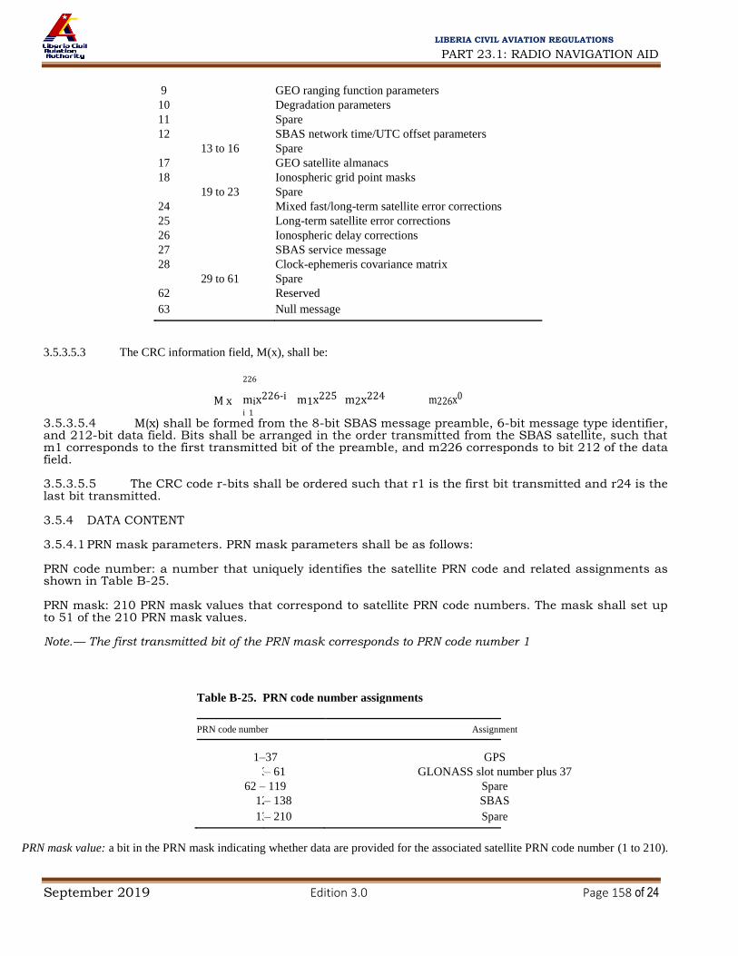
PART 23.1: RADIO NAVIGATION AID
September 2019 Edition 3.0 Page 158 of 24
LIBERIA CIVIL AVIATION REGULATIONS
9 GEO ranging function parameters
10 Degradation parameters
11 Spare
12 SBAS network time/UTC offset parameters
13 to 16 Spare
17 GEO satellite almanacs
18 Ionospheric grid point masks
19 to 23 Spare
24 Mixed fast/long-term satellite error corrections
25 Long-term satellite error corrections
26 Ionospheric delay corrections
27 SBAS service message
28 Clock-ephemeris covariance matrix
29 to 61 Spare
62 Reserved
63 Null message
3.5.3.5.3 The CRC information field, M(x), shall be:
226
M x mix226‐i m1x225 m2x224 m226x0 i 1
3.5.3.5.4 M(x) shall be formed from the 8-bit SBAS message preamble, 6-bit message type identifier, and 212-bit data field. Bits shall be arranged in the order transmitted from the SBAS satellite, such that m1 corresponds to the first transmitted bit of the preamble, and m226 corresponds to bit 212 of the data field. 3.5.3.5.5 The CRC code r-bits shall be ordered such that r1 is the first bit transmitted and r24 is the last bit transmitted. 3.5.4 DATA CONTENT 3.5.4.1 PRN mask parameters. PRN mask parameters shall be as follows: PRN code number: a number that uniquely identifies the satellite PRN code and related assignments as shown in Table B-25. PRN mask: 210 PRN mask values that correspond to satellite PRN code numbers. The mask shall set up to 51 of the 210 PRN mask values. Note.— The first transmitted bit of the PRN mask corresponds to PRN code number 1
Table B-25. PRN code number assignments
PRN code number Assignment
1–37 GPS
38 – 61 GLONASS slot number plus 37
62 – 119 Spare
120 – 138 SBAS
139 – 210 Spare
PRN mask value: a bit in the PRN mask indicating whether data are provided for the associated satellite PRN code number (1 to 210).

PART 23.1: RADIO NAVIGATION AID
September 2019 Edition 3.0 Page 159 of 24
LIBERIA CIVIL AVIATION REGULATIONS
Coding: 0 = data not provided 1 = data provided
PRN mask number: the sequence number (1 to 51) of the mask values set in the PRN mask.
Note.— The PRN mask number is “1” for the lowest satellite PRN number for which the PRN mask value is “1”.
Issue of data — PRN (IODP): an indicator that associates the correction data with a PRN mask.
Note.— Parameters are broadcast in the following messages: a) PRN mask (consisting of 210 PRN mask values) in Type 1 message; b) PRN mask number in Type 24, 25 and 28 messages; c) PRN code number in Type 17 message; and d) IODP in Type 1 to 5, 7, 24, 25 and 28 messages. 3.5.4.2 Geostationary orbit (GEO) ranging function parameters. GEO ranging function parameters shall be as follows:
t0,GEO: the reference time for the GEO ranging function data, expressed as the time after midnight of the current day.
: the position of the GEO at time t0,GEO.
˙ ˙ ˙ : the velocity of the GEO at time t0,GEO.
¨ ¨ ¨ : the acceleration of the GEO at time t0,GEO.
aGf0: the time offset of the GEO clock with respect to SNT, defined at t0,GEO.
aGf1: the drift rate of the GEO clock with respect to SNT.
User range accuracy (URA): an indicator of the root-mean-square ranging error, excluding atmospheric effects, as described in Table
B-26. Note.— All parameters are broadcast in Type 9 message.
Table B-26. User range accuracy
URA Accuracy (rms)
0 2 m
1 2.8 m
2 4 m
3 5.7 m
4 8 m
5 11.3 m
6 16 m
7 32 m
8 64 m
9 128 m
10 256 m
11 512 m

PART 23.1: RADIO NAVIGATION AID
September 2019 Edition 3.0 Page 160 of 24
LIBERIA CIVIL AVIATION REGULATIONS
12 1 024 m
13 2 048 m
14 4 096 m
15 “Do Not Use”
3.5.4.3 GEO almanac parameters. GEO almanac parameters shall be as follows: PRN code number: see 3.5.4.1.
Health and status: an indication of the functions provided by the SBAS. The service provider identifiers are
shown in Table B-27. Coding: Bit 0 (LSB) Ranging On (0) Off (1)
Bit 1 Precision corrections On (0) Off (1)
Bit 2
Satellite status and basic
corrections On (0) Off (1)
Bits 3 Spare
Bits 4 to 7 Service provider identifier Note.— A service provider ID of 14 is used for GBAS and is not applicable to SBAS.
, , , : the position of the GEO at time talmanac.
˙ , ˙
, ˙
, : the velocity of the GEO at time talmanac.
talmanac: the reference time for the GEO almanac data, expressed as the time after midnight of the current day. Note.— All parameters are broadcast in Type 17 message.
3.5.4.4 SATELLITE CORRECTION BROADCAST PARAMETERS
3.5.4.4.1 Long-term correction parameters shall be as follows:
Issue of data (IODi): an indicator that associates the long-term corrections for the ith satellite with the ephemeris
data broadcast by that satellite.
Note 1.— For GPS, the IODi matches the IODE and 8 LSBs of the IODC (3.1.1.3.1.4 and 3.1.1.3.2.2).
Note 2.— For GLONASS, the IODi indicates a period of time that GLONASS data are to be used with SBAS
data. It consists of two fields as shown in Table B-28.
δxi: for satellite i, the ephemeris correction for the x axis.
δyi: for satellite i, the ephemeris correction for the y axis.
δzi: for satellite i, the ephemeris correction for the z axis.
δai,f0: for satellite i, the ephemeris time correction.
δx˙i: for satellite i, ephemeris velocity correction for x axis.
δy˙i: for satellite i, ephemeris velocity correction for y axis.
δz˙i: for satellite i, ephemeris velocity correction for z axis.
δai,f1: for satellite i, rate of change of the ephemeris time correction.

PART 23.1: RADIO NAVIGATION AID
September 2019 Edition 3.0 Page 161 of 24
LIBERIA CIVIL AVIATION REGULATIONS
ti,LT: the time of applicability of the parameters δxi, δyi, δzi, δai,f0, δx˙ i, δy˙ i, δz˙i and δai,f1, expressed in seconds after midnight of
the current day. Velocity code: an indicator of the message format broadcast (Table B-48 and Table B-49). Coding: 0 = δx˙ i, δy˙ i, δz˙i and δai,f1 are not broadcast. 1 = δx˙ i, δy˙ i, δz˙i and δai,f1 are broadcast. Note.— All parameters are broadcast in Type 24 and 25 messages.
Table B-27. SBAS service provider identifiers
Identifier Service provider
0 WAAS
1 EGNOS
2 MSAS
3 GAGAN
4 SDCM
5 to 13 Spare
14, 15 Reserved
Table B-28. IODi for GLONASS satellites
MSB LSB
Validity interval (5 bits) Latency time (3 bits)
3.5.4.4.2 Fast correction parameters shall be as follows:
Fast correction (FCi): for satellite i, the pseudo-range correction for rapidly varying errors, other than
tropospheric or ionospheric errors, to be added to the pseudo-range after application of the long-term
correction.
Note.— The user receiver applies separate tropospheric corrections (3.5.8.4.2 and 3.5.8.4.3).
Fast correction type identifier: an indicator (0, 1, 2, 3) of whether the Type 24 message contains the fast correction and integrity data associated with the PRN mask numbers from Type 2, Type 3, Type 4 or Type 5 messages, respectively. Issue of data-fast correction (IODFj): an indicator that associates UDREIis with fast corrections. The index j
shall denote the message type (j = 2 to 5) to which IODFj applies (the fast correction type identifier +2). Note.— The fast correction type identifier is broadcast in Type 24 messages. The FCi are broadcast in Type 2 to 5, and Type 24 messages. The IODFj are broadcast in Type 2 to 6, and Type 24 messages.
3.5.4.5 Fast and long-term correction integrity parameters. Fast and long-term correction integrity
parameters shall be as follows:
UDREIi: an indicator that defines the σ2i,UDRE for satellite i as described in Table B-29.
Model variance of residual clock and ephemeris errors (σ2i,UDRE): the variance of a normal distribution
associated with the user differential range errors for satellite i after application of fast and long-term

PART 23.1: RADIO NAVIGATION AID
September 2019 Edition 3.0 Page 162 of 24
LIBERIA CIVIL AVIATION REGULATIONS
corrections, excluding atmospheric effects and used in horizontal protection level/vertical protection level
computations (3.5.5.6).
Note.— All parameters are broadcast in Type 2 to 6, and Type 24 messages.
3.5.4.6 Ionospheric correction parameters. Ionospheric correction parameters shall be as follows:
IGP mask: a set of 11 ionospheric grid point (IGP) band masks defined in Table B-30.
IGP band mask: a set of IGP mask values which correspond to all IGP locations in one of the 11 IGP bands
defined in Table B-30.
Table B-29. Evaluation of UDREIi
UDREIi σ2i,UDRE
0 0.0520 m2
1 0.0924 m2
2 0.1444 m2
3 0.2830 m2
4 0.4678 m2
5 0.8315 m2
6 1.2992 m2
7 1.8709 m2
8 2.5465 m2
9 3.3260 m2
10 5.1968 m2
11 20.7870 m2
12 230.9661 m2
13 2 078.695 m2
14 “Not Monitored”
15 “Do Not Use”
IGP mask value: a bit indicating whether data are provided within that IGP band for the associated IGP. Coding: 0 = data are not provided 1 = data are provided Number of IGP bands: the number of IGP band masks being broadcast. IGP band identifier: the number identifying the ionospheric band as defined in Table B-30.
IGP block identifier: the identifier of the IGP block. The IGP blocks are defined by dividing into groups of 15
IGPs the sequence of IGPs within an IGP band mask which have IGP mask values of “1”. The IGP blocks
are numbered in an order of IGP mask value transmission, starting with “0”.
Validity interval (V): the time interval for which the GLONASS ephemeris data are applicable (coded with an
offset of 30 s) as described in Table B-31.
Latency time (L): the time interval between the time the last GLONASS ephemeris has been received by the
ground segment and the time of transmission of the first bit of the long-term correction message at the GEO(tltc) as described in Table B-32. IODIk: an indication of when the kth IGP band mask changes.

PART 23.1: RADIO NAVIGATION AID
September 2019 Edition 3.0 Page 163 of 24
LIBERIA CIVIL AVIATION REGULATIONS
IGP vertical delay estimate: an estimate of the delay induced for a signal at 1 575.42 MHz if it traversed the
ionosphere vertically at the IGP. Coding: The bit pattern “111111111” indicates “Do Not Use”. GIVEIi: an indicator that defines the σ2
i,GIVE as described in Table B-33.
Model variance of residual ionospheric errors (σ2i,GIVE): the variance of a normal distribution associated with the
residual ionospheric vertical error at the IGP for an L1 signal. Note.— All parameters are broadcast in Type 18 and Type 26 messages.
Table B-30. IGP locations and band numbers
Transmission order in
IGP location IGP band mask
Band 0
180 W 75S, 65S, 55S, 50S, 45S, ..., 45N, 50N, 55N, 65N, 75N, 85N 1–28
175 W 55S, 50S, 45S, ..., 45N, 50N, 55N 29 – 51
170 W 75S, 65S, 55S, 50S, 45S, ..., 45N, 50N, 55N, 65N, 75N 52 – 78
235 W 55S, 50S, 45S, ..., 45N, 50N, 55N 79 – 101
230 W 75S, 65S, 55S, 50S, 45S, ..., 45N, 50N, 55N, 65N, 75N 102 – 128
155 W 55S, 50S, 45S, ..., 45N, 50N, 55N 129 – 151
150 W 75S, 65S, 55S, 50S, 45S, ..., 45N, 50N, 55N, 65N, 75N 152 – 178
145 W 55S, 50S, 45S, ..., 45N, 50N, 55N 179 – 201
Band 1
140 W 85S, 75S, 65S, 55S, 50S, 45S, ..., 45N, 50N, 55N, 65N, 75N 1–28
Transmission order in IGP location IGP band mask
135 W 55S, 50S, 45S, ..., 45N, 50N, 55N 29 – 51

PART 23.1: RADIO NAVIGATION AID
September 2019 Edition 3.0 Page 164 of 24
LIBERIA CIVIL AVIATION REGULATIONS
130 W 75S, 65S, 55S, 50S, 45S, ..., 45N, 50N, 55N, 65N, 75N 52 – 78
125 W 55S, 50S, 45S, ..., 45N, 50N, 55N 79 – 101
120 W 75S, 65S, 55S, 50S, 45S, ..., 45N, 50N, 55N, 65N, 75N 102 – 128
115 W 55S, 50S, 45S, ..., 45N, 50N, 55N 129 – 151
110 W 75S, 65S, 55S, 50S, 45S, ..., 45N, 50N, 55N, 65N, 75N 152 – 178
105 W 55S, 50S, 45S, ..., 45N, 50N, 55N 179 – 201
Band 2
100 W 75S, 65S, 55S, 50S, 45S, ..., 45N, 50N, 55N, 65N, 75N 1–27
95 W 55S, 50S, 45S, ..., 45N, 50N, 55N 28 – 50
90 W 75S, 65S, 55S, 50S, 45S, ..., 45N, 50N, 55N, 65N, 75N, 85N 51 – 78
85 W 55S, 50S, 45S, ..., 45N, 50N, 55N 79 – 101
80 W 75S, 65S, 55S, 50S, 45S, ..., 45N, 50N, 55N, 65N, 75N 102 – 128
75 W 55S, 50S, 45S, ..., 45N, 50N, 55N 129 – 151
70 W 75S, 65S, 55S, 50S, 45S, ..., 45N, 50N, 55N, 65N, 75N 152 – 178
65 W 55S, 50S, 45S, ..., 45N, 50N, 55N 179 – 201
Band 3
60 W 75S, 65S, 55S, 50S, 45S, ..., 45N, 50N, 55N, 65N, 75N 1–27
55 W 55S, 50S, 45S, ..., 45N, 50N, 55N 28 – 50
50 W 85S, 75S, 65S, 55S, 50S, 45S, ..., 45N, 50N, 55N, 65N, 75N 51 – 78
45 W 55S, 50S, 45S, ..., 45N, 50N, 55N 79 – 101
40 W 75S, 65S, 55S, 50S, 45S, ..., 45N, 50N, 55N, 65N, 75N 102 – 128
35 W 55S, 50S, 45S, ..., 45N, 50N, 55N 129 – 151
30 W 75S, 65S, 55S, 50S, 45S, ..., 45N, 50N, 55N, 65N, 75N 152 – 178
25 W 55S, 50S, 45S, ..., 45N, 50N, 55N 179 – 201

PART 23.1: RADIO NAVIGATION AID
September 2019 Edition 3.0 Page 165 of 24
LIBERIA CIVIL AVIATION REGULATIONS
Band 4
20 W 75S, 65S, 55S, 50S, 45S, ..., 45N, 50N, 55N, 65N, 75N 1–27
15 W 55S, 50S, 45S, ..., 45N, 50N, 55N 28 – 50
10 W 75S, 65S, 55S, 50S, 45S, ..., 45N, 50N, 55N, 65N, 75N 51 – 77
5 W 55S, 50S, 45S, ..., 45N, 50N, 55N 78 – 100
0 75S, 65S, 55S, 50S, 45S, ..., 45N, 50N, 55N, 65N, 75N, 85N 101 – 128
5 E 55S, 50S, 45S, ..., 45N, 50N, 55N 129 – 151
10 E 75S, 65S, 55S, 50S, 45S, ..., 45N, 50N, 55N, 65N, 75N 152 – 178
15 E 55S, 50S, 45S, ..., 45N, 50N, 55N 179 – 201
Band 5
20 E 75S, 65S, 55S, 50S, 45S, ..., 45N, 50N, 55N, 65N, 75N 1–27
25 E 55S, 50S, 45S, ..., 45N, 50N, 55N 28 – 50
Transmission order in
IGP location IGP band mask
30 E
75S, 65S, 55S, 50S, 45S, ..., 45N, 50N, 55N, 65N,
75N 51 – 77
35 E 55S, 50S, 45S, ..., 45N, 50N, 55N 78 – 100
40 E
85S, 75S, 65S, 55S, 50S, 45S, ..., 45N, 50N, 55N,
65N, 75N 101 – 128
45 E 55S, 50S, 45S, ..., 45N, 50N, 55N 129 – 151
50 E
75S, 65S, 55S, 50S, 45S, ..., 45N, 50N, 55N, 65N,
75N 152 – 178
55 E 55S, 50S, 45S, ..., 45N, 50N, 55N 179 – 201
Band 6
60 E 75S, 65S, 55S, 50S, 45S, ..., 45N, 50N, 55N, 65N, 75N 1 – 27
65 E 55S, 50S, 45S, ..., 45N, 50N, 55N 28 – 50

PART 23.1: RADIO NAVIGATION AID
September 2019 Edition 3.0 Page 166 of 24
LIBERIA CIVIL AVIATION REGULATIONS
70 E
75S, 65S, 55S, 50S, 45S, ..., 45N, 50N, 55N, 65N,
75N 51 – 77
75 E 55S, 50S, 45S, ..., 45N, 50N, 55N 78 – 100
80 E
75S, 65S, 55S, 50S, 45S, ..., 45N, 50N, 55N, 65N,
75N 101 – 127
85 E 55S, 50S, 45S, ..., 45N, 50N, 55N 128 – 150
90 E
75S, 65S, 55S, 50S, 45S, ..., 45N, 50N, 55N, 65N,
75N, 85N 151 – 178
95 E 55S, 50S, 45S, ..., 45N, 50N, 55N 179 – 201
Band 7
100 E
75S, 65S, 55S, 50S, 45S, ..., 45N, 50N, 55N, 65N,
75N 1 – 27
105 E 55S, 50S, 45S, ..., 45N, 50N, 55N 28 – 50
110 E
75S, 65S, 55S, 50S, 45S, ..., 45N, 50N, 55N, 65N,
75N 51 – 77
115 E 55S, 50S, 45S, ..., 45N, 50N, 55N 78 – 100
120 E 75S, 65S, 55S, 50S, 45S, ..., 45N, 50N, 55N, 65N, 75N 101 – 127
125 E 55S, 50S, 45S, ..., 45N, 50N, 55N 128 – 150
130 E
85S, 75S, 65S, 55S, 50S, 45S, ..., 45N, 50N, 55N,
65N, 75N 151 – 178
135 E 55S, 50S, 45S, ..., 45N, 50N, 55N 179 – 201
Band 8
140 E
75S, 65S, 55S, 50S, 45S, ..., 45N, 50N, 55N, 65N,
75N 1 – 27
145 E 55S, 50S, 45S, ..., 45N, 50N, 55N 28 – 50
150 E
75S, 65S, 55S, 50S, 45S, ..., 45N, 50N, 55N, 65N,
75N 51 – 77
155 E 55S, 50S, 45S, ..., 45N, 50N, 55N 78 – 100
230 E
75S, 65S, 55S, 50S, 45S, ..., 45N, 50N, 55N, 65N,
75N 101 – 127

PART 23.1: RADIO NAVIGATION AID
September 2019 Edition 3.0 Page 167 of 24
LIBERIA CIVIL AVIATION REGULATIONS
235 E 55S, 50S, 45S, ..., 45N, 50N, 55N 128 – 150
170 E
75S, 65S, 55S, 50S, 45S, ..., 45N, 50N, 55N, 65N,
75N 151 – 177
175 E 55S, 50S, 45S, ..., 45N, 50N, 55N 178 – 200
Band 9
60 N 180W, 175W, 170W, …, 235E, 170E, 175E 1 – 72
65 N 180W, 170W, 230W, …, 150E, 230E, 170E 73 – 108
70 N 180W, 170W, 230W, …, 150E, 230E, 170E 109 – 144
Transmission order in
IGP location IGP band mask
75 N 180W, 170W, 230W, …, 150E, 230E, 170E 145 – 180
85 N 180W, 150W, 120W, …, 90E, 120E, 150E 181 – 192
Band 10
60 S 180W, 175W, 170W, …, 235E, 170E, 175E 1–72
65 S 180W, 170W, 230W, …, 150E, 230E, 170E 73 – 108
70 S 180W, 170W, 230W, …, 150E, 230E, 170E 109 – 144
75 S 180W, 170W, 230W, …, 150E, 230E, 170E 145 – 180
85 S 170W, 140W, 110W, …, 100E, 130E, 230E 181 – 192
Table B-31. Validity interval
Data Bits used Range of values Resolution
Validity interval (V) 5 30 s to 960 s 30 s
Table B-32. Latency time
Data Bits used Range of values Resolution
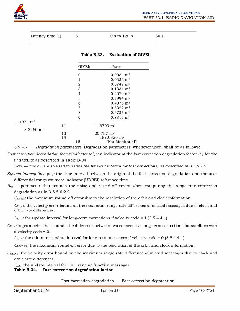
PART 23.1: RADIO NAVIGATION AID
September 2019 Edition 3.0 Page 168 of 24
LIBERIA CIVIL AVIATION REGULATIONS
Latency time (L) 3 0 s to 120 s 30 s
Table B-33. Evaluation of GIVEIi
GIVEIi σ2i,GIVE
0 0.0084 m2
1 0.0333 m2
2 0.0749 m2
3 0.1331 m2
4 0.2079 m2
5 0.2994 m2
6 0.4075 m2
7 0.5322 m2
8 0.6735 m2
9 0.8315 m2 10 1.1974 m2
11 1.8709 m2 12 3.3260 m2
13 20.787 m2 14 187.0826 m2
15 “Not Monitored”
3.5.4.7 Degradation parameters. Degradation parameters, whenever used, shall be as follows:
Fast correction degradation factor indicator (aii): an indicator of the fast correction degradation factor (ai) for the
ith satellite as described in Table B-34.
Note.— The aii is also used to define the time-out interval for fast corrections, as described in 3.5.8.1.2.
System latency time (tlat): the time interval between the origin of the fast correction degradation and the user
differential range estimate indicator (UDREI) reference time.
Brrc: a parameter that bounds the noise and round-off errors when computing the range rate correction
degradation as in 3.5.5.6.2.2.
Cltc_lsb: the maximum round-off error due to the resolution of the orbit and clock information. Cltc_v1: the velocity error bound on the maximum range rate difference of missed messages due to clock and
orbit rate differences. Iltc_v1: the update interval for long-term corrections if velocity code = 1 (3.5.4.4.1).
Cltc_v0: a parameter that bounds the difference between two consecutive long-term corrections for satellites with
a velocity code = 0. Iltc_v0: the minimum update interval for long-term messages if velocity code = 0 (3.5.4.4.1). CGEO_lsb: the maximum round-off error due to the resolution of the orbit and clock information.
CGEO_v: the velocity error bound on the maximum range rate difference of missed messages due to clock and
orbit rate differences. IGEO: the update interval for GEO ranging function messages.
Table B-34. Fast correction degradation factor
Fast correction degradation Fast correction degradation

PART 23.1: RADIO NAVIGATION AID
September 2019 Edition 3.0 Page 169 of 24
LIBERIA CIVIL AVIATION REGULATIONS
factor indicator (aii) factor (ai)
0 0.0 mm/s2
1 0.05 mm/s2
2 0.09 mm/s2
3 0.12 mm/s2
4 0.15 mm/s2
5 0.20 mm/s2
6 0.30 mm/s2
7 0.45 mm/s2
8 0.60 mm/s2
9 0.90 mm/s2
10 1.50 mm/s2
11 2.10 mm/s2
12 2.70 mm/s2
13 3.30 mm/s2
14 4.60 mm/s2
15 5.80 mm/s2
Cer: the bound on the residual error associated with using data beyond the precision approach/approach with
vertical guidance time-out. Ciono_step: the bound on the difference between successive ionospheric grid delay values. Iiono: the minimum update interval for ionospheric correction messages. Ciono ramp: the rate of change of the ionospheric corrections. RSSUDRE: the root-sum-square flag for fast and long-term correction residuals. Coding: 0 = correction residuals are linearly summed 1 = correction residuals are root-sum-squared RSSiono: the root-sum-square flag for ionospheric residuals.
Coding: 0 = correction residuals are linearly summed 1 = correction residuals are root-sum-squared Ccovariance: the term which is used to compensate for quantization effects when using the Type 28 message.
Note 1. — The parameters ai and tlat are broadcast in Type 7 message. All other parameters are broadcast
in Type 10 message. Note 2. — If message Type 28 is not broadcast, Ccovariance is not applicable. 3.5.4.8 Time parameters. Time parameters, whenever used, shall be as follows:
UTC standard identifier: an indication of the UTC reference source as defined in Table B-35.
GPS time-of-week count: the number of seconds that have passed since the transition from the previous GPS
week (similar to the GPS parameter in 3.1.1.2.6.1 but with a 1-second resolution).
Table B-35. UTC standard identifier
UTC standard identifier UTC standard
0 UTC as operated by the Communications Research Laboratory, Tokyo, Japan

PART 23.1: RADIO NAVIGATION AID
September 2019 Edition 3.0 Page 170 of 24
LIBERIA CIVIL AVIATION REGULATIONS
1 UTC as operated by the U.S. National Institute of Standards and Technology
2 UTC as operated by the U.S. Naval Observatory
3 UTC as operated by the International Bureau of Weights and Measures
4 Reserved for UTC as operated by a European laboratory
5 to 6 Spare
7 UTC not provided
GPS week number (week count): see 3.1.1.2.6.2. GLONASS indicator: a flag indicating if GLONASS time parameters are provided.
Coding: 0 = GLONASS time parameters are not provided 1 = GLONASS time parameters are provided
GLONASS time offset (δai,GLONASS): A parameter that represents the stable part of the offset between the
GLONASS time and the SBAS network time. Note.— If SBAS does not support GLONASS, δai,GLONASS is not applicable.
UTC parameters: A1SNT, A0SNT, t0t, WN t, tLS, WN LSF, DN and tLSF are as described in 3.1.1.3.3.6, with the
exception that the SBAS parameters relate SNT to UTC time, rather than GPS time. Note.— All parameters are broadcast in Type 12 message. 3.5.4.9 Service region parameters. Service region parameters shall be as follows: Issue of data, service (IODS): an indication of a change of the service provided in the region.
Number of service messages: the number of different Type 27 SBAS service messages being broadcast. (Value
is coded with an offset of 1.)
Service message number: a sequential number identifying the message within the currently broadcast set of
Type 27 messages (from 1 to number of service messages, coded with an offset of 1). Number of regions: the number of service regions for which coordinates are broadcast in the message. Priority code: an indication of a message precedence if two messages define overlapping regions. The
message with a higher value of priority code takes precedence. If priority codes are equal, the message with
the lower δUDRE takes precedence.
δUDRE indicator-inside: an indication of regional UDRE degradation factor (δUDRE) applicable at locations
inside any region defined in the message, in accordance with Table B-36.
δUDRE indicator-outside: an indication of regional UDRE degradation factor (δUDRE) applicable at locations
outside all regions defined in all current Type 27 messages, in accordance with Table B-36. Coordinate latitude: the latitude of one corner of a region. Coordinate longitude: the longitude of one corner of a region.
Region shape: an indication of whether a region is a triangle or quadrangle.

PART 23.1: RADIO NAVIGATION AID
September 2019 Edition 3.0 Page 171 of 24
LIBERIA CIVIL AVIATION REGULATIONS
Coding: 0 = triangle 1 = quadrangle
Note 1. — Coordinate 3 has Coordinate 1 latitude and Coordinate 2 longitude. If region is a quadrangle,
Coordinate 4 has Coordinate 2 latitude and Coordinate 1 longitude. Region boundary is formed by joining
coordinates in the sequence 1-2-3-1 (triangle) or 1-3-2-4-1 (quadrangle). Boundary segments have either
constant latitude, constant longitude, or constant slope in degrees of latitude per degree of longitude. The
change in latitude or longitude along any boundary segment between two coordinates is less than ±180
degrees. Note 2. — All parameters are broadcast in Type 27 message.
Table B-36. δUDRE indicator evaluation
δUDRE indicator δUDRE
0 1 1 1.1
2 1.25
3 1.5
4 2
5 3
6 4
7 5
8 6
9 8
10 10
11 20
12 30
13 40
14 50
15 100
3.5.4.10 Clock-ephemeris covariance matrix parameters. Clock-ephemeris covariance matrix parameters
shall be as follows: PRN mask number: see 3.5.4.1.
Scale exponent: A term to compute the scale factor used to code the Cholesky factorization elements.
Cholesky factorization elements (Ei,j): Elements of an upper triangle matrix which compresses the information
in the clock and ephemeris covariance matrix. These elements are used to compute the user differential
range estimate (UDRE) degradation factor (δUDRE) as a function of user position.
3.5.5 DEFINITIONS OF PROTOCOLS FOR DATA APPLICATION

PART 23.1: RADIO NAVIGATION AID
September 2019 Edition 3.0 Page 172 of 24
LIBERIA CIVIL AVIATION REGULATIONS
Note.— This section provides definitions of parameters used by the non-aircraft or aircraft elements that
are not transmitted. These parameters, necessary to ensure interoperability of SBAS, are used to determine
the navigation solution and its integrity (protection levels). 3.5.5.1 GEO POSITION AND CLOCK 3.5.5.1.1 GEO position estimate. The estimated position of a GEO at any time tk is:
XG XG ˙ ¨
XG 1
XG 2
^ Y ˙ ¨
t‐t0,GEO t–t0,GEO
YG G YG 2
YG
^ ZG ˙ ¨
ZG ZG ZG
3.5.5.1.2 GEO clock correction. The clock correction for a SBAS GEO satellite i is applied in accordance
with the following equation:
t = tG – ∆tG where
t = SBAS network time;
tG = GEO code phase time at transmission of message; and
ΔtG = GEO code phase offset.
3.5.5.1.2.1 GEO code phase offset (∆tG) at any time t is: ΔtG = aGf0 + aGf1 (t – t0,GEO)
where (t – t0,GEO) is corrected for end-of-day crossover. 3.5.5.2 LONG-TERM CORRECTIONS
3.5.5.2.1 GPS clock correction. The clock correction for a GPS satellite i is applied in accordance with
the following equation:
t = tSV,i – [( tSV,i)L1 + δΔtSV,i]
where t = SBAS network time; t = the GPS satellite time at transmission of message;
( t ) = the satellite PRN code phase offset as defined in 3.1.2.2; and
δΔtSV,I = the code phase offset correction.
3.5.5.2.1.1 The code phase offset correction (δΔtSV,i) for a GPS or SBAS satellite i at any time of day tk is:
δΔtSV,i = δai,f0 + δai,f1 (tk – ti,LT)
3.5.5.2.2 GLONASS clock correction. The clock correction for a GLONASS satellite i is applied in
accordance with the following equation:
t = tSV,i + τn(tb) – γn(tb)(tSV,i – tb) – δΔtSV,i
Where

PART 23.1: RADIO NAVIGATION AID
September 2019 Edition 3.0 Page 173 of 24
LIBERIA CIVIL AVIATION REGULATIONS
t = SBAS network
tSV,i = the GLONASS satellite time at transmission of message
tb, τn(tb), γn(tb) = the GLONASS time parameters as defined in 3.2.2.2
δΔtSV,i = the code phase offset correction
The code phase offset correction δΔtSV,i for a GLONASS satellite i is:
δΔtSV,i = δai,f0 + δai,f1(t – ti,LT) + δai,GLONASS
where (t – ti,LT) is corrected for end-of-day crossover. If the velocity code = 0, then δai,f1 = 0.
3.5.5.2.3 Satellite position correction. The SBAS-corrected vector for a core satellite constellation(s) or
SBAS satellite i at time t is:
xi x
i δxi δx˙ i
yi yi δyi δy˙ i t–ti,LT
zi corrected zi δzi δz˙i where (t – ti,LT) is corrected for end-of-day crossover; and [xi yi zi]T = the core satellite constellation(s) or SBAS satellite position vector as defined in 3.1.2.3, 3.2.2.3 and 3.5.5.1.1. If the velocity code = 0, then δx˙ i δy˙ i δz˙i T 0 0 0 T. 3.5.5.3 Pseudo-range corrections. The corrected pseudo-range at time t for satellite i is:
PRi,corrected = PRi + FCi + RRCi (t – ti,0f) + ICi + TCi
where
PRi = the measured pseudo-range after application of the satellite clock correction;
FCi = the fast correction;
RRCi = the range rate correction;
ICi = the ionospheric correction;
TCi = the tropospheric correction (negative value representing the troposphere delay); and
ti,0f = the time of applicability of the most recent fast corrections, which is the start of the epoch of the SNT second
that is coincident with the transmission at the SBAS satellite of the first symbol of the
message block.
3.5.5.4 Range rate corrections (RRC). The range rate correction for satellite i is:
RRCi
FCi,current
– FCi,previous
ti,0f
– ti,0f
__previous
where
FCi,current = the most recent fast correction;

PART 23.1: RADIO NAVIGATION AID
September 2019 Edition 3.0 Page 174 of 24
LIBERIA CIVIL AVIATION REGULATIONS
FCi,previous = a previous fast correction;
ti,0f = the time of applicability of FCi,current; and
ti,0f_previous = the time of applicability of FCi,previous.
3.5.5.5 BROADCAST IONOSPHERIC CORRECTIONS
3.5.5.5.1 Location of ionospheric pierce point (IPP). The location of an IPP is defined to be the intersection
of the line segment from the receiver to the satellite and an ellipsoid with constant height of 350 km above
the WGS-84 ellipsoid. This location is defined in WGS-84 latitude (φpp) and longitude (λpp). 3.5.5.5.2 Ionospheric corrections. The ionospheric correction for satellite i is:
ICi = – Fpp τvpp where
Fpp = obliquity factor = 1- τvpp = interpolated vertical ionospheric delay estimate (3.5.5.5.3);
Re = 6 378.1363 km;
θi = elevation angle of satellite i; and
hI = 350 km.
Note.— For GLONASS satellites, the ionospheric correction (ICi) is to be multiplied by the square of the ratio of
the GLONASS to the GPS frequencies (fGLONASS/fGPS)2. 3.5.5.5.3 Interpolated vertical ionospheric delay estimate. When four points are used for interpolation, the interpolated vertical ionospheric delay estimate at latitude φpp and longitude λ pp is: 4
τvpp
Wk τ
vk k 1
where
τvk: the broadcast grid point vertical delay values at the kth
corner of the IGP grid, as shown in Figure B-13
W1 = xpp ypp;
W2 = (1 – xpp) ypp;
W3 = (1 – xpp) (1 – ypp); and
W4 = xpp (1 – ypp). 3.5.5.5.3.1 For IPPs between N85° and S85°:
where
λ1 = longitude of IGPs west of IPP;
λ 2 = longitude of IGPs east of IPP;
φ1 = latitude of IGPs south of IPP; and
φ2 = latitude of IGPs north of IPP.

PART 23.1: RADIO NAVIGATION AID
September 2019 Edition 3.0 Page 175 of 24
LIBERIA CIVIL AVIATION REGULATIONS
Note.— If λ 1 and λ 2 cross 180 degrees of longitude, the calculation of xpp must account for the discontinuity in longitude
values.
3.5.5.5.3.2 For IPPs north of N85° or south of S85°:
xpp
λpp–λ3 1–2 ypp
ypp
90° where
λ 1 = longitude of the second IGP to the east of the IPP; λ 2 = longitude of the second IGP to the west of the IPP; λ 3 = longitude of the closest IGP to the west of the IPP; and λ 4 = longitude of the closest IGP to the east of the IPP.
When three points are used for interpolation, the interpolated vertical ionospheric delay estimated is:
3.5.5.5.3.3 For points between S75° and N75°:
where W1 = ypp; W2 = 1 – xpp – ypp; and W3 = xpp.
3.5.5.5.3.4 xpp and ypp are calculated as for four-point interpolation, except that λ 1 and φ1 are always
the longitude and latitude of IGP2, and λ2 and φ2 are the other longitude and latitude. IGP2 is always the
vertex opposite the hypotenuse of the triangle defined by the three points, IGP1 has the same longitude as
IGP2, and IGP3 has the same latitude as IGP2 (an example is shown in Figure B-14).
3.5.5.5.3.5 For points north of N75° and south of S75°, three-point interpolation is not supported. 3.5.5.5.4 Selection of ionospheric grid points (IGPs). The protocol for the selection of IGPs is:
a) For an IPP between N60° and S60°:
1) if four IGPs that define a 5-degree-by-5-degree cell around the IPP are set to “1” in the IGP
mask, they are selected; else, 2) if any three IGPs that define a 5-degree-by-5-degree triangle that circumscribes the IPP are set
to “1” in the IGP mask, they are selected; else, 3) if any four IGPs that define a 10-degree-by-10-degree cell around the IPP are set to “1” in the
IGP mask, they are selected; else, 4) if any three IGPs that define a 10-degree-by-10-degree triangle that circumscribes the IPP are
set to “1” in the IGP mask, they are selected; else,

PART 23.1: RADIO NAVIGATION AID
September 2019 Edition 3.0 Page 176 of 24
LIBERIA CIVIL AVIATION REGULATIONS
5) an ionospheric correction is not available.
b) For an IPP between N60° and N75° or between S60° and S75°:
1) if four IGPs that define a 5-degree-latitude-by-10-degree longitude cell around the IPP are set
to “1” in the IGP mask, they are selected; else, 2) if any three IGPs that define a 5-degree-latitude-by-10-degree longitude triangle that
circumscribes the IPP are set to “1” in the IGP mask, they are selected; else,
3) if any four IGPs that define a 10-degree-by-10-degree cell around the IPP are set to “1” in the
IGP mask, they are selected; else, 4) if any three IGPs that define a 10-degree-by-10-degree triangle that circumscribes the IPP are
set to “1” in the IGP mask, they are selected; else, 5) an ionospheric correction is not available.
c) For an IPP between N75° and N85° or between S75° and S85°:
1) if the two nearest IGPs at 75° and the two nearest IGPs at 85° (separated by 30° longitude if
Band 9 or 10 is used, separated by 90° otherwise) are set to “1” in the IGP mask, a 10-degree-by-10-
degree cell is created by linearly interpolating between the IGPs at 85° to obtain virtual IGPs at
longitudes equal to the longitudes of the IGPs at 75°; else, 2) an ionospheric correction is not available.
d) For an IPP north of N85°:
1) if the four IGPs at N85° latitude and longitudes of W180°, W90°, 0° and E90° are set to “1” in
the IGP mask, they are selected; else, 2) an ionospheric correction is not available.
e) For an IPP south of S85°:
1) if the four IGPs at S85° latitude and longitudes of W140°, W50°, E40° and E130° are set to “1”
in the IGP mask, they are selected; else, 2) an ionospheric correction is not available.
Note.— This selection is based only on the information provided in the mask, without regard to whether
the selected IGPs are monitored, “Not Monitored”, or “Do Not Use”. If any of the selected IGPs is identified
as “Do Not Use”, an ionospheric correction is not available. If four IGPs are selected, and one of the four is
identified as “Not Monitored”, then three-point interpolation is used if the IPP is within the triangular region
covered by the three corrections that are provided. 3.5.5.6 Protection levels. The horizontal protection level (HPL) and the vertical protection level (VPL)
are:
HPLSBA
S
KH,NP
A dmajor for en-route through non-precision approach (NPA) modes KH,PA

PART 23.1: RADIO NAVIGATION AID
September 2019 Edition 3.0 Page 177 of 24
LIBERIA CIVIL AVIATION REGULATIONS
dmajor for precision approach (PA) and approach with vertical guidance
(APV) modes
VPLSBAS = KV,PA × dV
where d2
V ∑Ni 1 sv,i
2σ2i = variance of model distribution that overbounds the true error distribution in the
vertical axis;
2 2 2 2 2
dmayo
r
dx
dy
dx
‐dy
dxy2 ;
2 2
where
dx2 ∑iN 1 sx,i2σi2 = variance of model distribution that overbounds the true error distribution in the x
axis;
dy2 ∑iN 1 sy,i2σi2 = variance of model distribution that overbounds the true error distribution in the y
axis;
dxy ∑iN
1
sx,i
sy,i
σi2 = covariance of model distribution in the x and y axis;
where
sx,i = the partial derivative of position error in the x-direction with respect to pseudo-range error on the ith
satellite;
sy,i = the partial derivative of position error in the y-direction with respect to pseudo-range error on the ith
satellite;
sV,i = the partial derivative of position error in the vertical direction with respect to pseudo-range error on the ith
satellite; and
σ2
i = σ2
i,flt + σ2i,UIRE + σ
2i,air + σ
2i,tropo.
The variances (σ2i,flt and σ2
i,UIRE) are defined in 3.5.5.6.2 and 3.5.5.6.3.1. The parameters (σ2i,air and
σ2i,tropo) are determined by the aircraft element (3.5.8.4.2 and 3.5.8.4.3).
The x and y axes are defined to be in the local horizontal plane, and the v axis represents local vertical.
For a general least-squares position solution, the projection matrix S is:
S
x,1 S
x,2 … S
x,N
S
Sy,1 S
y,2 … Sy,N
GTWG–1GTW Sv,1 S
v,2 … Sv,N
St,1 St,2 … St,N
where
Gi
= [–cos Eli cos Azi –cos Eli sin Azi –sin Eli 1] = ith
row of
G;
w
1 0 … 0
W
–1 0 w
2 … 0 ;
0 … wi

PART 23.1: RADIO NAVIGATION AID
September 2019 Edition 3.0 Page 178 of 24
LIBERIA CIVIL AVIATION REGULATIONS
El
i = the elevation angle of the ith
ranging source (in degrees);
A
zi =
the azimuth of the ith
ranging source taken counter-clockwise from the x axis in degrees;
and
wi = the inverse weight associated with satellite i = σ2
i. Note 1.— To improve readability, the subscript i was omitted from the protection matrix’s equation.
Note 2.— For an unweighted least-squares solution, the weighting matrix is an identity matrix (wi = 1).
3.5.5.6.1 Definition of K values. The K values are:
KH,NPA = 6.18;
KH,PA = 6.0; and
KV,PA = 5.33.
3.5.5.6.2 Definition of fast and long-term correction error model. If fast corrections and long-term correction/GEO ranging
parameters are applied, and degradation parameters are applied:
σ i,UDRE
δ
UDRE
ε fc
ε rrc
ε ltc
ε 2 , si RSSUDRE = 0 (Message Type
10)
σ2
er
i,flt
σ
δ
, si RSSUDRE = 1
(Message Type10)
i,UDRE UDRE
where
if using message Type 27, δUDRE is a region-specific term as defined in section 3.5.4.9, if using message Type 28, δUDRE is a satellite-specific term as defined in section 3.5.5.6.2.5, if
using neither message, δUDRE = 1.
If fast corrections and long-term corrections/GEO ranging parameters are applied, but degradation parameters are not
applied:
σ2
i,flt = [(σi,UDRE) (δUDRE) + 8m]2
3.5.5.6.2.1 Fast correction degradation. The degradation parameter for fast correction data is:
2
εfc a t‐tu tlat 2
Where
t = the current time;
tu = (UDREIi reference time): if IODFj ≠3, the start time of the SNT 1-second epoch that is coincident with the start
of the transmission of the message block that contains the most recent UDREIi data (Type 2 to 6, or Type 24
messages) that matches the IODFj of the fast correction being used. If IODFj = 3, the start time of the epoch of
the SNT 1-second epoch that is coincident with the start of transmission of the message that contains the fast
correction for the ith
satellite; and
tlat = (as defined in 3.5.4.7).
Note.— For UDREs broadcast in Type 2 to 5, and Type 24 messages, tu equals the time of applicability of the fast
corrections since they are in the same message. For UDREs broadcast in Type 6 message and if the IODF = 3, tu also

PART 23.1: RADIO NAVIGATION AID
September 2019 Edition 3.0 Page 179 of 24
LIBERIA CIVIL AVIATION REGULATIONS
equals the time of applicability of the fast corrections (t0f). For UDREs broadcast in Type 6 message and IODF ≠ 3, tu is
defined to be the time of transmission of the first bit of Type 6 message at the GEO.
3.5.5.6.2.2 Range rate correction degradation 3.5.5.6.2.2.1 If the RRC = 0, then εrrc = 0.
3.5.5.6.2.2.2 If the RRC ≠ 0 and IODF ≠ 3, the degradation parameter for fast correction data is:
εrrc
aIfc
0, si (IODF
actual–IODF
anterior MOD3 = 1
B
rrc t–t0f ,
si (IODFactual
–IODFanterior MOD3 1
4
Δt
3.5.5.6.2.2.3 If RRC ≠ 0 and IODF = 3, the degradation parameter for range rate data is:
0,
si
Δt–
I
fc 0
2
εrrc
a Δt–
I
f
c B
rrc
I
f
c
2
t–t0f , si Δt– 0
2
Δt 2
where
t = the current time;
IODFcurrent =
IODF associated with most recent fast
correction;
IODFprevious = IODF associated with previous fast correction;
t = ti,0f – ti,0f_previous; and
Ifc = the user time-out interval for fast corrections.
3.5.5.6.2.3 Long-term correction degradation
3.5.5.6.2.3.1 Core satellite constellation(s)
3.5.5.6.2.3.1.1 For velocity code = 1, the degradation parameter for long-term corrections of satellite i is:
εlt
c
0, if ti,LTt ti,LT Iltc_v1
Cltc_lsb + Cltc_v1
max
0,ti,LT t,t ti,LT Iltc_v1 , otherwise
3.5.5.6.2.3.1.2 For velocity code = 0, the degradation parameter for long-term corrections is:
εltc
Cltc t–tltc
_v0 I lt‐v0

PART 23.1: RADIO NAVIGATION AID
September 2019 Edition 3.0 Page 180 of 24
LIBERIA CIVIL AVIATION REGULATIONS
wher
e
lt‐v0
t = the current time;
tltc = the time of transmission of the first bit of the long-term correction message at the GEO; and
[x] = the greatest integer less than x. 3.5.5.6.2.3.2 GEO satellites. The degradation parameter for long-term corrections is:
εlt
c
0, if t0,GEOt t0,GEO IGEO
Cgeo_lsb + Cgeo_v max
0,t0,GEO t, t t0,GEO Igeo , otherwise
where t = the current time.
Note.— When long-term corrections are applied to a GEO satellite, the long-term correction degradation is
applied and the GEO navigation message degradation is not applied.
3.5.5.6.2.4 Degradation for en-route through non-precision approach
εe
r
0, if neither fast nor long-term corrections have timed out for precision approach/approach with vertical guidance
Cer, if fast or long-term corrections have timed out for precision approach/approach with vertical guidance
3.5.5.6.2.5 UDRE degradation factor calculated with message Type 28 data. The δUDRE is:
δ UD
RE =
IT⋅
C⋅I + ε
where c
i
x
I = iy ,
i
z
1
ix
iy = the unit vector from the user to the satellite in the WGS-84 ECEF coordinate frame
iz
C = RT·R
εC = Ccovariance · SF
SF = 2scale exponent–5
R = E·SF
E
1,1 E
1,2
E1,
3 E
1,4
E = 0 E
2,2
E2,
3 E2,4
0 0
E3,
3 E3,4
0 0 0 E
4,4

PART 23.1: RADIO NAVIGATION AID
September 2019 Edition 3.0 Page 181 of 24
LIBERIA CIVIL AVIATION REGULATIONS
3.5.5.6.3 Definition of ionospheric correction error model 3.5.5.6.3.1 Broadcast ionospheric corrections. If SBAS-based ionospheric corrections are applied, σ2
UIRE
is: σ2
UIRE = F2pp × σ2
UIVE
where Fpp = (as defined in 3.5.5.5.2); σ2UIVE ⋅σ2n,ionogrid or σ2UIVE ⋅ σ2n,ionogrid using the same ionospheric pierce point weights (Wn) and grid points selected for the ionospheric
correction (3.5.5.5). For each grid point:
2 σ ε iono
2, si RSS 0 Type 10 message GIVE iono
σ
σGIVE2
εiono2
,
i,ionogrid si RSSiono 1 Type 10 message
Where
εiono = Ciono_step
t–
tiono
+ Ciono_ramp (t – tiono);
t = Iiono
the current time;
tiono = the time of transmission of the first bit of the ionospheric correction message at the GEO; and
[x] = the greatest integer less than x.
Note.— For GLONASS satellites, both σGIVE and σIONO parameters are to be multiplied by the square of the
ratio of the GLONASS to the GPS frequencies (fGLONASS/fGPS)2. 3.5.5.6.3.2 Ionospheric corrections. If SBAS-based ionospheric corrections are not applied, σ2
UIRE is:
Tio
no
2
σUIRE2 2
MAX , F
pp τ
vert 5
Where
Tiono = the ionospheric delay estimated by the chosen model (GPS correction or other model);
Fpp = (as defined in 3.5.5.5.2); 9 m, 0 pp 20
τvert 4.5 m, 20 pp 55;y
φpp
6 m, 55 pp
= latitude of the ionospheric pierce point.
3.5.5.6.3.3 GLONASS clock. The degradation parameter for GLONASS clock correction is:
εGLONASS_CLOCK = CGLONASS_CLOCK • [t - tGLONASS_CLOCK]
Where

PART 23.1: RADIO NAVIGATION AID
September 2019 Edition 3.0 Page 182 of 24
LIBERIA CIVIL AVIATION REGULATIONS
t= the current time t GLONASS_CLOCK = the time of transmission of the first bit of the timing message (MT12) at the GEO
[sc] = the greatest integer less than sc.
Note 1.— For non-GLONASS satellites εGLONASS_CLOCK = 0.
Note 2.— CGLONASS_CLOCK = 0.00833 cm/s.
3.5.6 MESSAGE TABLES
Each SBAS message shall be coded in accordance with the corresponding message format defined in Tables B-37 through
B-53. All signed parameters in these tables shall be represented in two’s complement, with the sign bit occupying the MSB.
Note.— The range for the signed parameters is smaller than indicated, as the maximum positive value is constrained to be
one value less (the indicated value minus the resolution).
Table B-37. Type 0 “Do Not Use” message
Data content Bits used Range of values Resolution
Spare 212 — —
Table B-38. Type 1 PRN mask message
Data content Bits
used Range of values Resolution
For each of 210 PRN code numbers Mask value 1 0 or 1 1
IODP 2 0 to 3 1 Note.— All parameters are defined in 3.5.4.1.
Table B-39. Types 2 to 5 fast correction message
Data content Bits used Range of values Resolution
IODFj 2 0 to 3 1
IODP 2 0 to 3 1
For 13 slots
Fast correction (FCi) 12 ±256.000 m 0.125 m
For 13 slots
4 (see Table B-29) (see Table B-29)
UDREIi
Notes.—
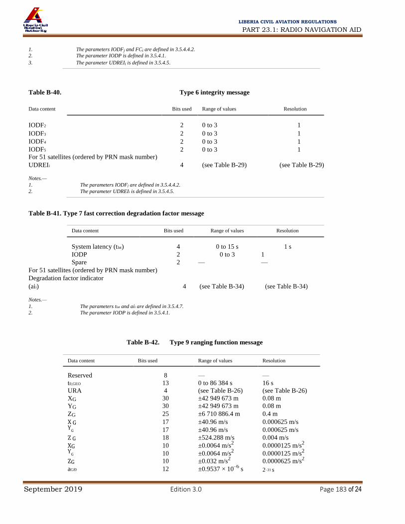
PART 23.1: RADIO NAVIGATION AID
September 2019 Edition 3.0 Page 183 of 24
LIBERIA CIVIL AVIATION REGULATIONS
1. The parameters IODFj and FCi are defined in 3.5.4.4.2.
2. The parameter IODP is defined in 3.5.4.1. 3. The parameter UDREIi is defined in 3.5.4.5.
Table B-40. Type 6 integrity message
Data content Bits used Range of values Resolution
IODF2 2 0 to 3 1
IODF3 2 0 to 3 1
IODF4 2 0 to 3 1
IODF5 2 0 to 3 1 For 51 satellites (ordered by PRN mask number)
UDREIi 4 (see Table B-29) (see Table B-29) Notes.— 1. The parameters IODFj are defined in 3.5.4.4.2. 2. The parameter UDREIi is defined in 3.5.4.5.
Table B-41. Type 7 fast correction degradation factor message
Data content Bits used Range of values Resolution
System latency (tlat) 4 0 to 15 s 1 s
IODP 2 0 to 3 1
Spare 2 — — For 51 satellites (ordered by PRN mask number)
Degradation factor indicator
(aii) 4 (see Table B-34) (see Table B-34) Notes.— 1. The parameters tlat and aii are defined in 3.5.4.7. 2. The parameter IODP is defined in 3.5.4.1.
Table B-42. Type 9 ranging function message
Data content Bits used Range of values Resolution
Reserved 8 — —
t0,GEO 13 0 to 86 384 s 16 s
URA 4 (see Table B-26) (see Table B-26)
XG 30 ±42 949 673 m 0.08 m
YG 30 ±42 949 673 m 0.08 m
ZG 25 ±6 710 886.4 m 0.4 m
X G 17 ±40.96 m/s 0.000625 m/s Y
G 17 ±40.96 m/s 0.000625 m/s
Z G 18 ±524.288 m/s 0.004 m/s
XG 10 ±0.0064 m/s2 0.0000125 m/s
2
YG 10 ±0.0064 m/s
2 0.0000125 m/s
2
ZG 10 ±0.032 m/s2 0.0000625 m/s
2
aGf0 12 ±0.9537 × 10⁻⁶
s 2–31 s

PART 23.1: RADIO NAVIGATION AID
September 2019 Edition 3.0 Page 184 of 24
LIBERIA CIVIL AVIATION REGULATIONS
aGf1 8 ±1.1642 × 10⁻¹⁰
s/s 2–40
s/s Note.— All parameters are defined in 3.5.4.2.
X G

PART 23.1: RADIO NAVIGATION AID
September 2019 Edition 3.0 Page 185 of 24
LIBERIA CIVIL AVIATION REGULATIONS
Table B-44. Type 12 SBAS network time/UTC message
Data content Bits used Range of values Resolution
A1SNT 24 ±7.45 × 10⁻⁹ s/s 2–50 s/s
A0SNT 32 ±1 s 2–30 s
t0t 8 0 to 602 112 s 4 096 s
WNt 8 0 to 255 weeks 1 week
∆tLS 8 ±128 s 1 s
WNLSF 8 0 to 255 weeks 1 week
DN 8 1 to 7 days 1 day
∆tLSF 8 ±128 s 1 s
UTC standard identifier 3 (see Table B-35) (see Table B-35)
GPS time-of-week (TOW) 20 0 to 604 799 s 1 s
GPS week number (WN) 10 0 to 1 023 weeks 1 week GLONASS indicator 1 0 or 1 1
δai, GLONASS (Note 2) 24 ±2.0 ⋅ 10–8 s 2.0 ⋅ 10–31 s
Spare 50 — —
Table B-45. Type 17 GEO almanac message
Data content Bits used Range of values Resolution
For each of 3 satellites Reserved 2 0 —
PRN code number 8 0 to 210 1
Health and status 8 — —
XG,A 15 ±42 598 400 m 2 600 m
YG,A 15 ±42 598 400 m 2 600 m
ZG,A 9 ±6 656 000 m 26 000 m
XG,A 3 ±40 m/s 10 m/s
YG,A 3 ±40 m/s 10 m/s
ZG,A 4 ±480 m/s 60 m/s
talmanac (applies to all three satellites) 11 0 to 86 336 s 64 s Note.— All parameters are defined in 3.5.4.3.
Table B-46. Type 18 IGP mask message
Data content Bits used Range of values Resolution

PART 23.1: RADIO NAVIGATION AID
September 2019 Edition 3.0 Page 186 of 24
LIBERIA CIVIL AVIATION REGULATIONS
Number of IGP bands 4 0 to 11 1
IGP band identifier 4 0 to 10 1
Issue of data — ionosphere (IODIk) 2 0 to 3 1
For 201 IGPs
IGP mask value 1 0 or 1 1
Spare 1 — — Note.— All parameters are defined in 3.5.4.6.
Table B-47. Type 24 mixed fast/long-term satellite error correction message
Data content Bits used Range of values Resolution
For 6 slots
Fast correction (FCi) 12 ±256.000 m 0.125 m
For 6 slots
4 (see Table B-31) (see Table B-31)
UDREIi
IODP 2 0 to 3 1
Fast correction type identifier 2 0 to 3 1
IODFj 2 0 to 3 1
Spare 4 — —
Type 25 half-message 106 — —
Notes.— 1. The parameters fast correction type identifier, IODFj, and FCi are defined in 3.5.4.4.2.
2. The parameter IODP is defined in 3.5.4.1. 3. The parameter UDREIi is defined in 3.5.4.5.
4. The long-term satellite error correction message is divided into two half-messages. The half message for a
velocity code = 0 is defined in Table B-48. The half message for a velocity code = 1 is defined in Table B-49.
Table B-48. Type 25 long-term satellite error correction half message (VELOCITY CODE = 0)
Data content Bits used Range of values Resolution
Velocity Code = 0 1 0 1
For 2 Satellites
PRN mask number 6 0 to 51 1
Issue of data (IODi) 8 0 to 255 1
δxi 9 ±32 m 0.125 m
δyi 9 ±32 m 0.125 m
δzi 9 ±32 m 0.125 m
δai,f0 10 ±2–22
s 2–31 s
IODP 2 0 to 3 1
Spare 1 — — Notes.— 1. The parameters PRN mask number and IODP are defined in 3.5.4.1. 2. All other parameters are defined in 3.5.4.4.1. Table B-49. Type 25 long-term satellite error correction half message (VELOCITY CODE = 1)
Data content Bits used Range of values Resolution

PART 23.1: RADIO NAVIGATION AID
September 2019 Edition 3.0 Page 187 of 24
LIBERIA CIVIL AVIATION REGULATIONS
For 1 Satellite Velocity Code = 1 1 1 1
PRN mask number 6 0 to 51 1
Issue of data (IODi) 8 0 to 255 1
δxi 11 ±128 m 0.125 m
δyi 11 ±128 m 0.125 m δzi 11 ±128 m 0.125 m
δai,f0 11 ±2
–
2
1 s 2
–
3
1 s
δx˙ i 8 ±0.0625 m/s 2–11
m/s
δy˙ i 8 ±0.0625 m/s 2–11
m/s
δz˙i 8 ±0.0625 m/s 2–11
m/s
δai,f1 8 ±2–32
s/s 2–39
s/s
Time-of-applicability (ti,LT) 13 0 to 86 384 s 16 s IODP 2 0 to 3 1
Notes.— 1. The parameters PRN mask number and IODP are defined in 3.5.4.1. 2. All other parameters are defined in 3.5.4.4.1.
Table B-50. Type 26 ionospheric delay message
Data content Bits used Range of values Resolution
IGP band identifier 4 0 to 10 1 IGP block identifier 4 0 to 13 1
For each of 15 grid points
IGP vertical delay estimate 9 0 to 63.875 m 0.125 m
Grid ionospheric vertical error indicator (GIVEIi) 4 (see Table B-33) (see Table B-33)
IODIk 2 0 to 3 1
Spare 7 — — Note.— All parameters are defined in 3.5.4.6.
Table B-51. Type 27 SBAS service message
Data content Bits used Range of values Resolution
Issue of data, service (IODS) 3 0 to 7 1
Number of service messages 3 1 to 8 1
Service message number 3 1 to 8 1
Number of regions 3 0 to 5 1
Priority code 2 0 to 3 1
δUDRE indicator-inside 4 0 to 15 1
δUDRE indicator-outside 4 0 to 15 1
For each of 5 regions
Coordinate 1 latitude 8 ±90° 1°

PART 23.1: RADIO NAVIGATION AID
September 2019 Edition 3.0 Page 188 of 24
LIBERIA CIVIL AVIATION REGULATIONS
Coordinate 1 longitude 9 ±180° 1°
Coordinate 2 latitude 8 ±90° 1°
Coordinate 2 longitude 9 ±180° 1°
Region shape 1 — —
Spare 15 — — Note.— All parameters are defined in 3.5.4.9. Table B-52. Type 63 null message
Data content Bits used Range of values Resolution
Spare 212 — —
Table B-53. Type 28 clock-ephemeris covariance matrix
Data content Bits used Range of values Resolution
IODP 2 0 to 3 1
For two satellites
PRN mask number 6 0 to 51 1
Scale exponent 3 0 to 7 1
E1,1 9 0 to 511 1
E2,2 9 0 to 511 1
E3,3 9 0 to 511 1
E4,4 9 0 to 511 1
E1,2 10 ±512 1
E1,3 10 ±512 1
E1,4 10 ±512 1
E2,3 10 ±512 1
E2,4 10 ±512 1
E3,4 10 ±512 1 Notes.— 1. The parameters PRN mask number and IODP are defined in 3.5.4.1. 2. All other parameters are defined in 3.5.4.10.
3.5.7 NON-AIRCRAFT ELEMENTS
Note 1.— Depending on the level of service offered by a particular SBAS, different functions can be implemented as described
in Chapter 3, 3.7.3.4.2.
Note 2.— The parameters that are referred to in this section are defined in 3.5.4.
3.5.7.1 GENERAL
3.5.7.1.1 Required data and broadcast intervals. SBAS shall broadcast the data required for the supported functions as shown
in Table B-54. If the SBAS broadcasts data that are not required for a particular function, the requirements for that data

PART 23.1: RADIO NAVIGATION AID
September 2019 Edition 3.0 Page 189 of 24
LIBERIA CIVIL AVIATION REGULATIONS
supporting other functions shall apply. The maximum interval between broadcasts for all data of each data type provided shall
be as defined in Table B-54. 3.5.7.1.2 SBAS radio frequency monitoring. The SBAS shall monitor the SBAS satellite parameters shown in Table B-55 and
take the indicated action.
Note.— SBAS may broadcast null messages (Type 63 messages) in each time slot for which no other data are broadcast.
3.5.7.1.3 “Do Not Use”. SBAS shall broadcast a “Do Not Use” message (Type 0 message) when necessary to inform users
not to use the SBAS satellite ranging function and its broadcast data.
3.5.7.1.4 The Doppler shift in the GEO satellite signal seen at any fixed location within the GEO footprint for any GEO shall
not exceed ±450 Hz.
Note.— This maximum Doppler shift corresponds approximately to the maximum GEO satellite orbit inclination that can be
supported by the coding ranges for Type 9 and Type 17 messages.
3.5.7.1.5 Geostationary orbit (GEO) ranging function parameters. Each SBAS satellite shall broadcast geostationary orbit
(GEO) ranging function parameters (defined in 3.5.4.2).
Note.— It is necessary to broadcast geostationary orbit ranging function parameters even when a ranging function is not
provided, so that airborne receivers may implement a positive identification of the broadcasting SBAS satellite. When ranging
is not provided, the accuracy of the Type 17 data (and Type 9 data) only needs to support the acquisition of the satellite.
3.5.7.1.5.1 The error in the Doppler shift of a GEO satellite derived from any Type 9 message that has not timed out, with
respect to the true GEO Doppler shift seen at any fixed location within the GEO footprint, shall not exceed ±210 Hz.
3. 5.7.1.6 Almanac data. Each SBAS satellite shall broadcast almanac data (defined in 3.5.4.3) for all SBAS satellites of the
same service provider.
3.5.7.1.6.1 The error in the estimated position of the satellite derived from any Type 17 message broadcast within the previous
15 minutes, with respect to the true satellite position, shall not exceed 3 000 km.
3.5.7.1.6.2 The separation distance between the estimated position of the satellite derived from any Type 17 message broadcast
within the previous 15 minutes and the position of the satellite derived from the GEO ranging parameters in any Type 9 message
that has not timed out shall not exceed 200 km.
3.5.7.1.6.3 The error in the Doppler shift of a GEO satellite derived from any Type 17 message broadcast within the previous
15 minutes, with respect to the true GEO Doppler shift seen at any fixed location within the GEO footprint, shall not exceed
±210 Hz.
3.5.7.1.6.4 SBAS shall not broadcast almanac data for any SBAS satellite from a different service provider for which the
position estimated from the almanac data broadcast within the previous 15 minutes would be within 200 km of the position of
any of its own GEOs as derived from the GEO ranging parameters from any Type 9 message that has not timed out.
3.5.7.1.6.5 Where the estimated position of a GEO satellite providing a ranging function, derived from the Type 17 message broadcast within the previous 15 minutes, is within 200 km of the position of another GEO satellite of the same service provider, derived from a Type 9 message for this GEO that has not timed out, the GEO UDRE value shall be set sufficiently large to account for the possibility that a user could misidentify the PRN of the GEO providing the ranging function. 3.5.7.1.6.6 The health and status parameter shall indicate the satellite status and the service provider identifier, as defined in
3.5.4.3.
3.5.7.1.6.7 Unused almanac slots in Type 17 messages shall be coded with a PRN code number of “0”.
3.5.7.1.6.8 The service provider shall ensure the correctness of the service provider ID broadcast in any almanac.

PART 23.1: RADIO NAVIGATION AID
September 2019 Edition 3.0 Page 190 of 24
LIBERIA CIVIL AVIATION REGULATIONS
3.5.7.2 Ranging function. If an SBAS provides a ranging function, it shall comply with the requirements contained in this
section in addition to the requirements of 3.5.7.1.
3.5.7.2.1 Performance requirements
Note.— See Chapter 3, 3.7.3.4.2.1.
3.5.7.2.2 Ranging function data. SBAS shall broadcast ranging function data such that the SBAS satellite position error
projected on the line-of-sight to any user in the satellite footprint is less than 256 metres. Each SBAS satellite shall broadcast
a URA representing an estimate of the standard deviation of the ranging errors referenced to SNT.
3.5.7.3 GNSS satellite status function. If an SBAS provides a satellite status function, it shall also comply with the requirements
contained in this section.
Note.— An SBAS may be able to provide integrity on some GPS satellites that are designated either marginal or unhealthy.
3.5.7.3.1 Performance of satellite status functions. Given any valid combination of active data, the probability of a horizontal
error exceeding the HPLSBAS (as defined in 3.5.5.6) for longer than 8 consecutive seconds shall be less than 10–7
in any hour,
assuming a user with zero latency. Note.— Active data is defined to be data that have not timed out per 3.5.8.1.2. This requirement includes core satellite
constellation(s) and SBAS failures.
3.5.7.3.2 PRN mask and Issue of data — PRN (IODP). SBAS shall broadcast a PRN mask and IODP (Type 1 message). The
PRN mask values shall indicate whether or not data are being provided for each GNSS satellite. The IODP shall change when
there is a change in the PRN mask. The change of IODP in Type 1 messages shall occur before the IODP changes in any other
message. The IODP in Type 2 to 5, 7, 24 and 25 messages shall equal the IODP broadcast in the PRN mask message (Type 1
message) used to designate the satellites for which data are provided in that message.
Table B-54. Data broadcast intervals and supported functions
Maximum GNSS Basic Precise Associated broadcast satellite differential differential message Data type interval Ranging status correction correction types
Clock-Ephemeris covariance matrix 120 s 28
SBAS in test mode 6 s 0
PRN mask 120 s R R R 1
UDREI 6 s R* R R 2 to 6, 24
Fast corrections Ifc/2 R* R R 2 to 5, 24
(see Note 4)
Long-term corrections 120 s R* R R 24, 25
GEO ranging function data 120 s R R R R 9
Fast correction degradation 120 s R* R R 7
Degradation parameters 120 s R 10
Ionospheric grid mask 300 s R 18
Ionospheric corrections, GIVEI 300 s R 26
Timing data 300 s R R R R 12
(see Note 3) (see Note 3) (see Note 3) (see Note 3)
Almanac data 300 s R R R R 17
Service level 300 s 27 Notes.— 1. “R” indicates that the data must be broadcast to support the function. 2. “R*” indicates special coding as described in 3.5.7.3.3.

PART 23.1: RADIO NAVIGATION AID
September 2019 Edition 3.0 Page 191 of 24
LIBERIA CIVIL AVIATION REGULATIONS
3. Type 12 messages are only required if data are provided for GLONASS satellites. 4. Ifc refers to the PA/APV time-out interval for fast corrections, as defined in Table B-57.
Table B-55. SBAS radio frequency monitoring
Parameter Reference Alarm limit Required action
Signal power level Chapter 3, minimum = –161 dBW Minimum: cease ranging function (Note 1).
3.7.3.4.4.3 maximum = –153 dBW Maximum: cease broadcast.
(Note 2)
Modulation Chapter 3, monitor for Cease ranging function (Note 1).
3.7.3.4.4.5 waveform distortion
SNT-to-GPS time Chapter 3, N/A Cease ranging function unless URA reflects error.
3.7.3.4.5 (Note 3)
Carrier frequency 3.5.2.1 N/A Cease ranging function unless σ2
UDRE and URA reflect error.
stability (Note 3)
Code/frequency 3.5.2.4 N/A Cease ranging function unless σ 2UDRE and URA reflect error.
coherence (Note 3)
Maximum code 3.5.2.6 N/A Cease ranging function unless σ 2UDRE and URA reflect error.
phase deviation (Notes 2 and 3)
Convolutional 3.5.2.9 all transmit messages Cease broadcast.
encoding are erroneous Notes.— 1. Ceasing the ranging function is accomplished by broadcasting a URA and σ 2UDRE of “Do Not Use” for that SBAS satellite.
2. These parameters can be monitored by their impact on the received signal quality (C/N0 impact), since that is the impact on the user.
3. Alarm limits are not specified because the induced error is acceptable, provided it is represented in the σ 2UDRE and URA parameters. If the error
cannot be represented, the ranging function must cease.
3.5.7.3.2.1 Recommendation.— When the PRN mask is changed, SBAS should repeat the Type 1 message several times
before referencing it in other messages to ensure that users receive the new mask.
3.5.7.3.3 Integrity data. If SBAS does not provide the basic differential correction function, it shall transmit fast corrections,
long-term corrections and fast correction degradation parameters coded to zero for all visible satellites indicated in the PRN
mask.
3.5.7.3.3.1 If SBAS does not provide the basic differential correction function, SBAS shall indicate that the satellite is
unhealthy (“Do Not Use”) if the pseudo-range error exceeds 150 metres.
3.5.7.3.3.2 If SBAS does not provide the basic differential correction function, SBAS shall indicate that the satellite is “Not
Monitored” if the pseudo-range error cannot be determined.
3.5.7.3.3.3 If SBAS does not provide the basic differential correction function, SBAS shall transmit a UDREIi of 13 if the
satellite is not “Do Not Use” or “Not Monitored”. 3.5.7.3.3.4 The IODFj parameter in Type 2 to 5, 6 or 24 messages shall be equal to 3.

PART 23.1: RADIO NAVIGATION AID
September 2019 Edition 3.0 Page 192 of 24
LIBERIA CIVIL AVIATION REGULATIONS
3.5.7.4 Basic differential correction function. If an SBAS provides a basic differential correction function, it shall comply with
the requirements contained in this section in addition to the GNSS satellite status function requirements defined in 3.5.7.3.
3.5.7.4.1 Performance of basic differential correction function. Given any valid combination of active data, the probability of
a horizontal error exceeding the HPLSBAS (as defined in 3.5.5.6) for longer than 8 consecutive seconds shall be less than 10–7
in any hour, assuming a user with zero latency. Note.— Active data is defined to be data that has not timed out per 3.5.8.1.2. This requirement includes core satellite
constellation(s) and SBAS failures.
3.5.7.4.2 Long-term corrections. Except for SBAS satellites from the same service provider, SBAS shall determine and
broadcast long-term corrections for each visible GNSS satellite (see Note) indicated in the PRN mask (PRN mask value equal
to “1”). The long-term corrections shall be such that the core satellite constellation(s) satellite position error projected on the
line-of-sight to any user in the satellite footprint after application of these long-term corrections is less than 256 metres. For
each GLONASS satellite, SBAS shall translate satellite coordinates into WGS-84 as defined in 3.5.5.2 prior to determining
the long-term corrections. For each GPS satellite, the broadcast IOD shall match both the GPS IODE and 8 LSBs of IODC
associated with the clock and ephemeris data used to compute the corrections (3.1.1.3.1.4 and 3.1.1.3.2.2). Upon transmission
of a new ephemeris by a GPS satellite, SBAS shall continue to use the old ephemeris to determine the fast and long-term error
corrections for at least 2 minutes and not more than 4 minutes. For each GLONASS satellite, SBAS shall compute and
broadcast an IOD that consists of a latency and a validity interval as defined in 3.5.4.4.1.
Note.— The criteria for satellite visibility include the locations of reference stations and the achieved mask angle at those
locations.
3.5.7.4.2.1 Recommendation.— To ensure accurate range rate corrections, SBAS should minimize discontinuities in the
satellite ephemerides after application of long-term corrections.
3.5.7.4.3 Fast corrections. SBAS shall determine fast corrections for each visible GNSS satellite indicated in the PRN mask
(PRN mask value equal to “1”). Unless the IODF = 3, each time any fast correction data in Type j (j = 2, 3, 4 or 5) message
changes, the IODFj shall sequence “0, 1, 2, 0, ...”.
Note.— If there is an alarm condition, the IODFj may equal 3 (see 3.5.7.4.5).
3.5.7.4.4 Timing data. If data are provided for GLONASS, SBAS shall broadcast the timing message (Type 12 message)
including GLONASS time offset as defined in Table B-44.
3.5.7.4.5 Integrity data. For each satellite for which corrections are provided, SBAS shall broadcast integrity data (UDREIi
and, optionally, Type 27 or 28 message data to calculate δ UDRE) such that the integrity requirement in 3.5.7.4.1 is met. If the
fast corrections or long-term corrections exceed their coding range, SBAS shall indicate that the satellite is unhealthy (“Do
Not Use”). If σ2
i,UDRE cannot be determined, SBAS shall indicate that the satellite is “Not Monitored”.
If Type 6 message is used to broadcast σ 2i,UDRE, then:
a) the IODFj shall match the IODFj for the fast corrections received in Type j message to which the σ 2
i,UDRE apply; or
b) the IODFj shall equal 3 if the σ 2
i,UDRE apply to all valid fast corrections received in Type j message which have not
timed out.
3.5.7.4.6 Degradation data. SBAS shall broadcast degradation parameters (Type 7 message) to indicate the applicable time
out interval for fast corrections and ensure that the integrity requirement in 3.5.7.4.1 is met.
3.5.7.5 Precise differential correction function. If SBAS provides a precise differential correction function, it shall comply
with the requirements contained in this section in addition to the basic differential correction function requirements in 3.5.7.4.

PART 23.1: RADIO NAVIGATION AID
September 2019 Edition 3.0 Page 193 of 24
LIBERIA CIVIL AVIATION REGULATIONS
3.5.7.5.1 Performance of precise differential correction function. Given any valid combination of active data, the probability of an
out-of-tolerance condition for longer than the relevant time-to-alert shall be less than 2 × 10⁻⁷
during any approach, assuming a user
with zero latency. The time-to-alert shall be 5.2 seconds for an SBAS that supports precision approach or APV-II operations, and 8
seconds for an SBAS that supports APV-I operations. An out-of-tolerance condition shall be defined as a horizontal error exceeding
the HPLSBAS or a vertical error exceeding the VPLSBAS (as defined in 3.5.5.6). When an out-of-tolerance condition is detected, the
resulting alert message (broadcast in a Type 2 to 5 and 6, 24, 26 or 27 messages) shall be repeated three times after the initial
notification of the alert condition for a total of four times in 4 seconds. Note 1.— Active data is defined to be data that has not timed out per 3.5.8.1.2. This requirement includes core satellite
constellation(s) and SBAS failures.
Note 2.— Subsequent messages can be transmitted at the normal update rate.
3.5.7.5.2 Ionospheric grid point (IGP) mask. SBAS shall broadcast an IGP mask and IODIk (up to 11 Type 18 messages,
corresponding to the 11 IGP bands). The IGP mask values shall indicate whether or not data are being provided for each IGP. If IGP Band 9 is used, then the IGP mask values for IGPs north of 55°N in Bands 0 through 8 shall be set to “0”. If IGP Band
10 is used, then the IGP mask values for IGPs south of 55°S in Bands 0 through 8 shall be set to “0”. The IODIk shall change
when there is a change of IGP mask values in the kth
band. The new IGP mask shall be broadcast in a Type 18 message before
it is referenced in a related Type 26 message. The IODIk in Type 26 message shall equal the IODIk broadcast in the IGP mask
message (Type 18 message) used to designate the IGPs for which data are provided in that message. 3.5.7.5.2.1 Recommendation.— When the IGP mask is changed, SBAS should repeat the Type 18 message several times
before referencing it in a Type 26 message to ensure that users receive the new mask. The same IODIk should be used for all
bands. 3.5.7.5.3 Ionospheric corrections. SBAS shall broadcast ionospheric corrections for the IGPs designated in the IGP mask (IGP
mask values equal to “1”).
3.5.7.5.4 Ionospheric integrity data . For each IGP for which corrections are provided, SBAS shall broadcast GIVEI data such
that the integrity requirement in 3.5.7.5.1 is met. If the ionospheric correction or σ 2i,GIVE exceed their coding range, SBAS
shall indicate the status “Do Not Use” (designated in the correction data, 3.5.4.6) for the IGP. If σ 2
i,GIVE cannot be determined,
SBAS shall indicate that the IGP is “Not Monitored” (designated in the GIVEI coding). 3.5.7.5.5 Degradation data. SBAS shall broadcast degradation parameters (Type 10 message) such that the integrity
requirement in 3.5.7.5.1 is met.
3.5.7.6 OPTIONAL FUNCTIONS
3.5.7.6.1 Timing data. If UTC time parameters are broadcast, they shall be as defined in 3.5.4.8 (Type 12 message).
3.5.7.6.2 Service indication. If service indication data are broadcast, they shall be as defined in 3.5.4.9 (Type 27 message) and
Type 28 messages shall not be broadcast. The IODS in all Type 27 messages shall increment when there is a change in any
Type 27 message data.
3.5.7.6.3 Clock-ephemeris covariance matrix. If clock-ephemeris covariance matrix data are broadcast, they shall be broadcast
for all monitored satellites as defined in 3.5.4.10 (Type 28 message) and Type 27 messages shall not be broadcast.
3.5.7.7 MONITORING
3.5.7.7.1 SBAS radio frequency monitoring. The SBAS shall monitor the SBAS satellite parameters shown in Table B-55 and
take the indicated action.
Note.— In addition to the radio frequency monitoring requirements in this section, it will be necessary to make special provisions to
monitor pseudo-range acceleration specified in Chapter 3, 3.7.3.4.2.1.5, and carrier phase noise specified in 3.5.2.2 and correlation
loss in 3.5.2.5, unless analysis and testing shows that these parameters cannot exceed the stated limits.

PART 23.1: RADIO NAVIGATION AID
September 2019 Edition 3.0 Page 194 of 24
LIBERIA CIVIL AVIATION REGULATIONS
3.5.7.7.2 Data monitoring. SBAS shall monitor the satellite signals to detect conditions that will result in improper operation
of differential processing for airborne receivers with the tracking performance defined in Attachment D, 8.11.
3.5.7.7.2.1 The ground subsystem shall use the strongest correlation peak in all receivers used to generate the pseudo-range
corrections.
3.5.7.7.2.2 The ground subsystem shall also detect conditions that cause more than one zero crossing for airborne receivers
that use the Early-Late discriminator function as defined in Attachment D, 8.11.
3.5.7.7.2.3 The monitor action shall be to set UDRE to “Do Not Use” for the satellite.
3.5.7.7.2.4 SBAS shall monitor all active data that can be used by any user within the service area.
3.5.7.7.2.5 SBAS shall raise an alarm within 5.2 seconds if any combination of active data and GNSS signals-in-space results
in an out-of-tolerance condition for precision approach or APV II (3.5.7.5.1).
3.5.7.7.2.6 SBAS shall raise an alarm within 8 seconds if any combination of active data and GNSS signals-in-space results in
an out-of-tolerance condition for en-route through APV I (3.5.7.4.1).
Note.— The monitoring applies to all failure conditions, including failures in core satellite constellation(s) or SBAS satellites.
This monitoring assumes that the aircraft element complies with the requirements of RTCA/DO-229C, except as superseded
by 3.5.8 and Attachment D, 8.11.
3.5.7.8 Robustness to core satellite constellation(s) failures. Upon occurrence of a core satellite constellation(s) satellite
anomaly, SBAS shall continue to operate normally using the available healthy satellite signals that can be tracked.
3.5.8 AIRCRAFT ELEMENTS
Note 1.— The parameters that are referred to in this section are defined in 3.5.4.
Note 2.— Some of the requirements of this section may not apply to equipment that integrates additional navigation sensors,
such as equipment that integrates SBAS with inertial navigation sensors.
3.5.8.1 SBAS-capable GNSS receiver. Except as specifically noted, the SBAS-capable GNSS receiver shall process the signals
of the SBAS and meet the requirements specified in 3.1.3.1 (GPS receiver) and/or 3.2.3.1 (GLONASS receiver). Pseudo-range
measurements for each satellite shall be smoothed using carrier measurements and a smoothing filter which deviates less than
0.1 metre within 200 seconds after initialization, relative to the steady-state response of the filter defined in 3.6.5.1 in the
presence of drift between the code phase and integrated carrier phase of up to 0.01 metre per second.
3.5.8.1.1 GEO satellite acquisition. The receiver shall be able to acquire and track GEO satellites for which a stationary receiver
at the user receiver location would experience a Doppler shift as large as ±450 Hz.
3.5.8.1.2 Conditions for use of data. The receiver shall use data from an SBAS message only if the CRC of this message has
been verified. Reception of a Type 0 message from an SBAS satellite shall result in deselection of that satellite and all data
from that satellite shall be discarded for at least 1 minute. For GPS satellites, the receiver shall apply long-term corrections
only if the IOD matches both the IODE and 8 least significant bits of the IODC. For GLONASS satellites, the receiver shall
apply long-term corrections only if the time of reception (tr) of the GLONASS ephemeris is inside the following IOD validity
interval, as defined in 3.5.4.4.1:
tLT – L – V ≤ tr ≤ tLT – L

PART 23.1: RADIO NAVIGATION AID
September 2019 Edition 3.0 Page 195 of 24
LIBERIA CIVIL AVIATION REGULATIONS
Note 1.— For SBAS satellites, there is no mechanism that links GEO ranging function data (Type 9 message) and long-term
corrections.
Note 2.— This requirement does not imply that the receiver has to stop tracking the SBAS satellite.
3.5.8.1.2.1 SBAS satellite identification. Upon acquisition or re-acquisition of an SBAS satellite, the receiver shall not use
SBAS satellite data unless the calculated separation between the satellite position derived from its GEO ranging function
parameters and the satellite position derived from the almanac message most recently received from the same service provider
within the last 15 minutes is less than 200 km.
Note.— This check ensures that a receiver will not mistake one SBAS satellite for another due to cross-correlation during
acquisition or re-acquisition.
3.5.8.1.2.2 The receiver shall use integrity or correction data only if the IODP associated with that data matches the IODP
associated with the PRN mask.
3.5.8.1.2.3 The receiver shall use SBAS-provided ionospheric data (IGP vertical delay estimate and GIVEIi) only if the IODIk
associated with that data in a Type 26 message matches the IODIk associated with the relevant IGP band mask transmitted in
a Type 18 message.
3.5.8.1.2.4 The receiver shall use the most recently received integrity data for which the IODFj equals 3 or the IODFj matches
the IODFj associated with the fast correction data being applied (if corrections are provided).
3.5.8.1.2.5 The receiver shall apply any regional degradation to the σ2
i,UDRE as defined by a Type 27 service message. If a
Type 27 message with a new IODS indicates a higher δUDRE for the user location, the higher δUDRE shall be applied
immediately. A lower δUDRE in a new Type 27 message shall not be applied until the complete set of messages with the new
IODS has been received.
3.5.8.1.2.6 The receiver shall apply satellite-specific degradation to the σi,UDRE2 as defined by a Type 28 clock-ephemeris
covariance matrix message. The δUDRE derived from a Type 28 message shall be applied immediately.
3.5.8.1.2.7 In the event of a loss of four successive SBAS messages, the receiver shall no longer support SBAS-based precision
approach or APV operations.
3.5.8.1.2.8 The receiver shall not use a broadcast data parameter after it has timed out as defined in Table B-56.
3.5.8.1.2.9 The receiver shall not use a fast correction if t for the associated RRC exceeds the time-out interval for fast
corrections, or if the age of the RRC exceeds 8 t.
3.5.8.1.2.10 The calculation of the RRC shall be reinitialized if a “Do Not Use” or “Not Monitored” indication is received for
that satellite.
3.5.8.1.2.11 For SBAS-based precision approach or APV operations, the receiver shall only use satellites with elevation angles
at or above 5 degrees.
3.5.8.1.2.12 The receiver shall no longer support SBAS-based precision approach or APV operation using a particular satellite
if the UDREIi received is greater than or equal to 12.
Table B-56. Data time-out intervals
Associated En-route, terminal, Precision approach, Data message types NPA time-out APV time-out

PART 23.1: RADIO NAVIGATION AID
September 2019 Edition 3.0 Page 196 of 24
LIBERIA CIVIL AVIATION REGULATIONS
Clock-ephemeris covariance matrix 28 360 240 SBAS in test mode 0 N/A N/A
PRN mask 1 600 s 600 s
UDREI 2 to 6, 24 18 s 12 s
Fast corrections 2 to 5, 24 (see Table B-57) (see Table B-57)
Long-term corrections 24, 25 360 s 240 s
GEO ranging function data 9 360 s 240 s
Fast correction degradation 7 360 s 240 s
Degradation parameters 10 360 s 240 s
Ionospheric grid mask 18 1 200 s 1 200 s
Ionospheric corrections, GIVEI 26 600 s 600 s
Timing data 12 86 400 s 86 400 s
GLONASS time offset 12 600 s 600 s
Almanac data 17 None None
Service level 27 86 400 s 86 400 s Note.— The time-out intervals are defined from the end of the reception of a message.
Table B-57. Fast correction time-out interval evaluation
Fast correction NPA time-out PA/APV time-out degradation factor interval for fast interval for fast
indicator (aii) corrections (Ifc) corrections (Ifc)
0 180 s 120 s
1 180 s 120 s
2 153 s 102 s
3 135 s 90 s
4 135 s 90 s
5 117 s 78 s
6 99 s 66 s
7 81 s 54 s
8 63 s 42 s
9 45 s 30 s
10 45 s 30 s
11 27 s 18 s
12 27 s 18 s
13 27 s 18 s
14 18 s 12 s
15 18 s 12 s
3.5.8.2 RANGING FUNCTION
3.5.8.2.1 Precision approach and APV operations. The root-mean-square (1 sigma) of the total airborne error contribution to
the error in a corrected pseudo-range for an SBAS satellite at the minimum received signal power level (Chapter 3, 3.7.3.4.4.3)
under the worst interference environment as defined in 3.7 shall be less than or equal to 1.8 metres, excluding multipath effects,
tropospheric and ionospheric residual errors.
Note.— The aircraft element will bound the errors caused by multipath and troposphere (3.5.8.4.1). For the purpose of
predicting service, the multipath error is assumed to be less than 0.6 metres (1 sigma).
3.5.8.2.2 Departure, en-route, terminal, and non-precision approach operations. The root-mean-square (1 sigma) of the total
airborne contribution to the error in a corrected pseudo-range for an SBAS satellite at the minimum received signal power level

PART 23.1: RADIO NAVIGATION AID
September 2019 Edition 3.0 Page 197 of 24
LIBERIA CIVIL AVIATION REGULATIONS
(Chapter 3, 3.7.3.4.4.3) under the worst interference environment as defined in 3.7 shall be less than or equal to 5 metres,
excluding multipath, tropospheric and ionospheric errors.
3.5.8.2.3 SBAS satellite position
3.5.8.2.3.1 Position computation. The receiver shall decode Type 9 message and determine the code phase offset and position
(XG, YG, ZG) of the SBAS satellite.
3.5.8.2.3.2 SBAS satellite identification. The receiver shall discriminate between SBAS satellites.
Note.— This requirement applies to false acquisition of a satellite due to cross-correlation.
3.5.8.2.4 Almanac data
3.5.8.2.4.1 Recommendation.— The almanac data provided by the SBAS should be used for acquisition.
Note.— Health and status information provided in the GEO almanac data does not override or invalidate data provided in
other SBAS messages. The use of bits 0 to 2 by airborne equipment is optional; there are no requirements covering their usage.
3.5.8.3 GNSS satellite status function. The receiver shall exclude satellites from the position solution if they are identified as
“Do Not Use” by SBAS. If SBAS-provided integrity is used, the receiver shall not be required to exclude GPS satellites based
on the GPS-provided ephemeris health flag as required in 3.1.3.1.1 or to exclude GLONASS satellites based on GLONASS-
provided ephemeris health flag as required in 3.2.3.1.1.
Note 1.— In the case of a satellite designated marginal or unhealthy by the core satellite constellation(s) health flag, SBAS
may be able to broadcast ephemeris and clock corrections that will allow the user to continue using the satellite.
Note 2.— If satellites identified as “Not Monitored” by SBAS are used in the position solution, integrity is not provided by
SBAS. ABAS or GBAS may be used to provide integrity, if available.
3.5.8.4 BASIC AND PRECISE DIFFERENTIAL FUNCTIONS
3.5.8.4.1 Core satellite constellation(s) ranging accuracy. The root-mean-square (1 sigma) of the total airborne contribution
to the error in a corrected pseudo-range for a GPS satellite at the minimum received signal power level (Chapter 3, 3.7.3.1.7.4)
under the worst interference environment as defined in 3.7 shall be less than or equal to 0.4 metres, excluding multipath effects,
tropospheric and ionospheric residual errors. The RMS of the total airborne contribution to the error in a corrected pseudo-
range for a GLONASS satellite at the minimum received signal power level (Chapter 3, 3.2.5.4) under the worst interference
environment as defined in 3.7 shall be less than or equal to 0.8 metres, excluding multipath effects, tropospheric and
ionospheric residual errors.
3.5.8.4.2 Precision approach and APV operations
3.5.8.4.2.1 The receiver shall compute and apply long-term corrections, fast corrections, range rate corrections and the
broadcast ionospheric corrections. For GLONASS satellites, the ionospheric corrections received from the SBAS shall be
multiplied by the square of the ratio of GLONASS to GPS frequencies (fGLONASS/fGPS)2.
3.5.8.4.2.2 The receiver shall use a weighted-least-squares position solution.

PART 23.1: RADIO NAVIGATION AID
September 2019 Edition 3.0 Page 198 of 24
LIBERIA CIVIL AVIATION REGULATIONS
3.5.8.4.2.3 The receiver shall apply a tropospheric model such that residual pseudo-range errors have a mean value (µ) less
than 0.15 metres and a 1 sigma deviation less than 0.07 metres.
Note.— A model was developed that meets this requirement. Guidance is provided in Attachment D, 6.5.4. 3.5.8.4.2.4 The receiver shall compute and apply horizontal and vertical protection levels defined in 3.5.5.6. In this
computation, σtropo shall be: 1 0.12 m
0.002 sin2 θi
where θi is the elevation angle of the ith
satellite.
In addition, σair shall satisfy the condition that a normal distribution with zero mean and a standard deviation equal to σair
bounds the error distribution for residual aircraft pseudo-range errors as follows:
∞
y
y
fn x dx Q
for all 0 and
σ σ y
–y
fn x dx Q y for
all y
0 σ σ
–∞
Where
fn(x) = probability density function of the residual aircraft pseudo-range error and
∞ t2
Q(x) = 1
e–
2 dt
√2π
x
Note.— The standard allowance for airborne multipath defined in 3.6.5.5.1 may be used to bound the multipath errors.
3.5.8.4.2.5 The parameters that define the approach path for a single precision approach or APV shall be contained in the FAS
data block. Note 1.— The FAS path is a line in space defined by the landing threshold point/fictitious threshold point (LTP/FTP), flight
path alignment point (FPAP), threshold crossing height (TCH) and glide path angle (GPA). The local level plane for the
approach is a plane perpendicular to the local vertical passing through the LTP/FTP (i.e. tangent to the ellipsoid at the
LTP/FTP). Local vertical for the approach is normal to the WGS-84 ellipsoid at the LTP/FTP. The glide path intercept point
(GPIP) is where the final approach path intercepts the local level plane.
Note 2.— For SBAS, FAS data blocks are stored in airborne databases. The format of the data for validation of a cyclic
redundancy check is shown in Attachment D, 6.6. It differs from the GBAS FAS data block in 3.6.4.5.
3.5.8.4.2.5.1 FAS data block parameters shall be as follows (see Table B-57A):
Operation type: straight-in approach procedure or other operation types.
Coding: 0 = straight-in approach procedure
1 to 15 = spare
SBAS service provider ID: indicates the service provider associated with this FAS data block.
Coding: See Table B-27. 14 = FAS data block is to be used with GBAS only. 15 = FAS data block can be used with any SBAS service provider.

PART 23.1: RADIO NAVIGATION AID
September 2019 Edition 3.0 Page 199 of 24
LIBERIA CIVIL AVIATION REGULATIONS
Airport ID: the three- or four-letter designator used to designate an airport.
Coding: Each character is coded using the lower 6 bits of its IA-5 representation. For each character, b1 is transmitted first,
and 2 zero bits are appended after b6, so that 8 bits are transmitted for each character. Only upper case letters, numeric digits
and IA-5 “space” are used. The rightmost character is transmitted first. For a three-character airport ID, the rightmost (first
transmitted) character shall be IA-5 “space”.
Runway number: the runway orientation, point-in- space final approach course, or SBAS circling only procedure course
rounded to the nearest 10 degrees and truncated to two characters.
Coding: 01 to 36 = runway number
Note.— For heliport operations, the runway number value is the integer nearest to one tenth of the final approach course,
except when that integer is zero, in which case the runway number is 36.
Runway letter: the one-letter designator used, as necessary, to differentiate between parallel runways.
Coding: 0 = no letter 1 = R (right)
2 = C (centre) 3 = L (left)
Approach performance designator: this field is not used by SBAS.
Route indicator: a “blank” or the one-letter identifier used to differentiate between multiple procedures to the same runway
end.
Note.— Procedures are considered to be different even if they only differ by the missed approach segment.
Coding: The letter is coded using bits b1 through b5 of its IA-5 representation. Bit b1 is transmitted first. Only upper case
letters, excluding “I” and “O”, or IA-5 “space” (blank) are used. Blank indicates that there is only one procedure to the runway
end. For multiple procedures to the same runway end, the route indicator is coded using a letter starting from Z and moving
backward in the alphabet for additional procedures. Reference path data selector (RPDS): this field is not used by SBAS.
Table B-57A. Final approach segment (FAS) data block
Data content Bits used Range of values Resolution
Operation type 4 0 to 15 1 SBAS service provider ID 4 0 to 15 1
Airport ID 32 — —
Runway number 6 01 to 36 1
Runway letter 2 — —
Approach performance designator 3 0 to 7 1
Route indicator 5 — —
Reference path data selector 8 0 to 48 1
Reference path identifier 32 — —
LTP/FTP latitude 32 ±90.0°
0.0005
arcsec
LTP/FTP longitude 32 ±180.0°
0.0005
arcsec

PART 23.1: RADIO NAVIGATION AID
September 2019 Edition 3.0 Page 200 of 24
LIBERIA CIVIL AVIATION REGULATIONS
LTP/FTP height 16 –512.0 to 6 041.5 m 0.1 m
FPAP latitude 24 ±1.0°
0.0005
arcsec
FPAP longitude 24 ±1.0°
0.0005
arcsec
Approach TCH (Note 1) 15 0 to 1 638.35 m or 0.05 m or
0 to 3 276.7 ft 0.1 ft
Approach TCH units selector 1 — —
Glide path angle (GPA) 16 0 to 90.0° 0.01°
Course width 8 80 to 143.75 m 0.25 m
Length offset 8 0 to 2 032 m 8 m
Horizontal alert limit (HAL) 8 0 to 51.0 m 0.2 m
Vertical alert limit (VAL) (Note 2) 8 0 to 51.0 m 0.2 m
Final approach segment CRC 32 — Note 1.— Information can be provided in either feet or metres as indicated by the approach TCH unit selector. Note 2.— A VAL of 0 indicates that the vertical deviations cannot be used (i.e., a lateral only approach). This does not preclude providing advisory vertical guidance on such approaches, refer to FAA AC 20-138(). Reference path identifier (RPI): four characters used to uniquely designate the reference path. The four characters consist of
three alphanumeric characters plus a blank or four alphanumeric characters. Note.— The best industry practice matches the 2nd and 3rd character encoding to the encoded runway number. The last
character is a letter starting from A or a “blank.”
Coding: Each character is coded using bits b1 through b6 of its IA-5 representation. For each character, b1 is transmitted first,
and 2 zero bits are appended after b6 so that 8 bits are transmitted for each character. Only upper case letters, numeric digits
and IA-5 “space” are used. The rightmost character is transmitted first. For a three-character reference path identifier, the
rightmost (first transmitted) character shall be IA-5 “space”. Note.— The LTP/FTP is a point over which the FAS path passes at a height above the LTP/FTP height specified by the TCH.
LTP/FTP latitude: the latitude of the LTP/FTP point in arc seconds.
Coding: positive value denotes north
latitude. negative value denotes south latitude.
LTP/FTP longitude: the longitude of the LTP/FTP point in arc seconds.
Coding: positive value denotes east longitude. negative value denotes west longitude.
LTP/FTP height: the height of the LTP/FTP above the WGS-84 ellipsoid.
Coding: This field is coded as an unsigned fixed-point number with an offset of –512 metres. A value of zero in this field
places the LTP/FTP 512 metres below the earth ellipsoid.
Note.— The FPAP is a point at the same height as the LTP/FTP that is used to define the alignment of the approach. The origin
of angular deviations in the lateral direction is defined to be 305 metres (1 000 ft) beyond the FPAP along the lateral FAS
path. For an approach aligned with the runway, the FPAP is at or beyond the stop end of the runway.
∆FPAP latitude: the difference of latitude of the runway FPAP from the LTP/FTP in arc seconds.
Coding: Positive value denotes the FPAP latitude north of LTP/FTP latitude. Negative value denotes the FPAP latitude south of the LTP/FTP latitude.

PART 23.1: RADIO NAVIGATION AID
September 2019 Edition 3.0 Page 201 of 24
LIBERIA CIVIL AVIATION REGULATIONS
∆FPAP longitude: the difference of longitude of the runway FPAP from the LTP/FTP in arc seconds.
Coding: Positive value indicates the FPAP longitude east of LTP/FTP longitude. Negative value indicates the FPAP longitude west of LTP/FTP longitude.
Approach TCH: the height of the FAS path above the LTP/FTP defined in either feet or metres as indicated by the TCH units
selector.
Approach TCH units selector: the units used to describe the TCH.
Coding: 0 = feet 1 = metres
Glide path angle (GPA): the angle of the FAS path with respect to the horizontal plane tangent to the WGS-84 ellipsoid at the
LTP/FTP.
Course width: the lateral displacement from the path defined by the FAS at the LTP/FTP at which full-scale deflection of a
course deviation indicator is attained.
Coding: This field is coded as an unsigned fixed-point number with an offset of 80 metres. A value of zero in this field indicates
a course width of 80 metres at the LTP/FTP.
Length offset: the distance from the stop end of the runway to the FPAP.
Coding: 1111 1111 = not provided
HAL: Horizontal alert limit to be used during the approach in metres.
VAL: Vertical alert limit to be used during the approach in metres.
Final approach segment CRC: the 32-bit CRC appended to the end of each FAS data block in order to ensure approach data
integrity. The 32-bit final approach segment CRC shall be calculated in accordance with 3.9. The length of the CRC code shall
be k = 32 bits.
The CRC generator polynomial shall be:
G(x) = x32
+ x31
+ x24
+ x22
+ x16
+ x14
+ x8 + x
7 + x
5 + x
3 + x + 1
The CRC information field, M(x), shall be:
288
M x m x288–i m x287 m x286 . . . m x0 i 1 2 288 i 1
M(x) shall be formed from all bits of the associated FAS data block, excluding the CRC. Bits shall be arranged in the order
transmitted, such that m1 corresponds to the LSB of the operation type field, and m288 corresponds to the MSB of the Vertical
Alert Limit (VAL) field. The CRC shall be ordered such that r1 is the LSB and r32 is the MSB. 3.5.8.4.2.5.2 For precision approach and APV operations, the service provider ID broadcast Type 17 message shall be identical
to the service provider ID in the FAS data block, except if ID equals 15 in the FAS data block. Note.— If the service provider ID in the FAS data block equals 15, then any service provider can be used. If the service provider
ID in the FAS data block equals 14, then SBAS precise differential corrections cannot be used for the approach.

PART 23.1: RADIO NAVIGATION AID
September 2019 Edition 3.0 Page 202 of 24
LIBERIA CIVIL AVIATION REGULATIONS
3.5.8.4.2.5.3 SBAS FAS data points accuracy. The survey error of all the FAS data points, relative to WGS-84, shall be less
than 0.25 metres vertical and 1 metre horizontal.
3.5.8.4.3 Departure, en-route, terminal, and non-precision approach operations
3.5.8.4.3.1 The receiver shall compute and apply long-term corrections, fast corrections and range rate corrections.
3.5.8.4.3.2 The receiver shall compute and apply ionospheric corrections.
Note.— Two methods of computing ionospheric corrections are provided in 3.1.2.4 and 3.5.5.5.2.
3.5.8.4.3.3 The receiver shall apply a tropospheric model such that residual pseudo-range errors have a mean value (µ) less
than 0.15 metres and a standard deviation less than 0.07 metres.
Note.— A model was developed that meets this requirement. Guidance is provided in Attachment D, 6.5.4.
3.5.8.4.3.4 The receiver shall comput e and apply horizontal and vertical protection levels as defined in 3.5.5.6. In this
computation, stropo shall be:
1 0.12 m
0.002 sin2 θi
where θi is the elevation angle of the ith
satellite.
In addition, σair shall satisfy the condition that a normal distribution with zero mean and standard deviation equal to σair bounds
the error distribution for residual aircraft pseudo-range errors as follows:
∞
y
y
fn x dx Q
for all 0 and
σ σ
y
–y
fn x dx Q y
for all y
0 σ σ
–∞
where
fn(x) = probability density function of the residual aircraft pseudo-range error and
∞ t2
Q(x) = 1
e–
2 dt
√2π
x Note.— The standard allowance for airborne multipath defined in 3.6.5.5.1 may be used to bound the multipath errors.
3.5.8.4.4 Recommendation.— For departure, en-route, terminal, and non-precision approach operations, the receiver should
use the broadcast ionospheric corrections, when available, and a tropospheric model with performance equal to that specified
in 3.5.8.4.3.
3.5.9 INTERFACE BETWEEN SBAS
Note.— Guidance material on the interface between different SBAS service providers is given in Attachment D, 6.3. 3.6 Ground-based augmentation system (GBAS) and ground-based regional augmentation system (GRAS)

PART 23.1: RADIO NAVIGATION AID
September 2019 Edition 3.0 Page 203 of 24
LIBERIA CIVIL AVIATION REGULATIONS
Note.— In this section, except where specifically annotated, reference to approach with vertical guidance (APV) means APV-
I and APV-II.
3.6.1 GENERAL
The GBAS shall consist of a ground subsystem and an aircraft subsystem. The GBAS ground subsystem shall provide data
and corrections for the GNSS ranging signals over a digital VHF data broadcast to the aircraft subsystem. The GRAS ground
subsystem shall consist of one or more GBAS ground subsystems. Note.— Guidance material is provided in Attachment D, 7.1.
3.6.2 RF CHARACTERISTICS
3.6.2.1 Carrier frequency stability. The carrier frequency of the data broadcast shall be maintained within ±0.0002 per cent of
the assigned frequency. 3.6.2.2 Bit-to-phase-change encoding . GBAS messages shall be assembled into symbols, each consisting of 3 consecutive
message bits. The end of the message shall be padded by 1 or 2 fill bits if necessary to form the last 3-bit symbol of the
message. Symbols shall be converted to D8PSK carrier phase shifts ( k) in accordance with Table B-58.
Note.— The carrier phase for the kth
symbol ( k) is given by: k = k-1 + k.. The D8PSK signal may be produced as shown in
Figure B-19 by combining two quadrature RF signals which are independently suppressed-carrier amplitude-modulated by
base band filtered impulses. A positive increase in k represents a counterclockwise rotation in the complex I-Q plane of Figure
B-19.
3.6.2.3 Modulation wave form and pulse shaping filters. The output of differential phase encoder shall be filtered by a pulse
shaping filter whose output, s(t), is described as follows: k ∞
s t ejϕk h (t – kT
wher
e
k –∞
h = the impulse response of the raised cosine filter;
k = (as defined in 3.6.2.2);
t = time; and
T = the duration of each symbol = 1/10 500 second.
This pulse shaping filter shall have a nominal complex frequency response of a raised-cosine filter with α = 0.6. The time
response, h(t), and frequency response, H(f), of the base band filters shall be as follows:
sin
πt
cos
παt
h t
T T
πt 1
–
2αt 2
T T
1
for
0 f
1 – α
2T
π

PART 23.1: RADIO NAVIGATION AID
September 2019 Edition 3.0 Page 204 of 24
LIBERIA CIVIL AVIATION REGULATIONS
H f 1–sin
2α
2fT – 1
for
1–α
f
1 α
2
2T
2T
0
for
f
1 α
2T
The output s(t) of the pulse shaping filter shall modulate the carrier.
3.6.2.4 Error vector magnitude. The error vector magnitude of the transmitted signal shall be less than 6.5 per cent root-
mean-square (1 sigma). 3.6.2.5 RF data rate. The symbol rate shall be 10 500 symbols per second ±0.005 per cent, resulting in a nominal bit rate of
31 500 bits per second.
Table B-58. Data encoding
Message bits Symbol phase shift
I3k-2 I3k-1 I3k k
0 0 0 0π/4
0 0 1 1π/4
0 1 1 2π/4
0 1 0 3π/4
1 1 0 4π/4
1 1 1 5π/4
1 0 1 6π/4
1 0 0 7π/4 Note.— Ij is the jth bit of the burst to be transmitted, where I1 is the first
bit of the training sequence.
3.6.2.6 Emissions in unassigned time slots. Under all operating conditions, the maximum power over a 25 kHz channel
bandwidth, centred on the assigned frequency, when measured over any unassigned time slot, shall not exceed –105 dBc
referenced to the authorized transmitter power.
Note.— If the authorized transmitter power is higher than 150 W, the –105 dBc may not protect reception of emissions in a
slot assigned to another desired transmitter for receivers within 200 metres from the undesired transmitting antenna.
3.6.3 DATA STRUCTURE
3.6.3.1 TRANSMITTER TIMING
3.6.3.1.1 Data broadcast timing structure. The time division multiple access (TDMA) timing structure shall be based on frames
and time slots. Each frame shall be 500 milliseconds in duration. There shall be 2 such frames contained in each 1-second UTC
epoch. The first of these frames shall start at the beginning of the UTC epoch and the second frame shall start 0.5 seconds after
the beginning of the UTC epoch. The frame shall be time division multiplexed such that it shall consist of 8 individual time
slots (A to H) of 62.5-millisecond duration.

PART 23.1: RADIO NAVIGATION AID
September 2019 Edition 3.0 Page 205 of 24
LIBERIA CIVIL AVIATION REGULATIONS
3.6.3.1.2 Bursts. Each assigned time slot shall contain at most 1 burst. To initiate the use of a time slot, the GBAS shall
broadcast a burst in that time slot in each of 5 consecutive frames. For each time slot in use, the ground subsystem shall
broadcast a burst in at least 1 frame of every 5 consecutive frames.
Note 1.— Bursts contain one or more messages and may be of variable length up to the maximum allowed within the slot as
required by 3.6.3.2.
Note 2.— During time slot initiation, the airborne receiver may not receive the first 4 bursts.
3.6.3.1.3 Timing budget for bursts
3.6.3.1.3.1 Each burst shall be contained in a 62.5-millisecond time slot.
3.6.3.1.3.2 The beginning of the burst shall occur 95.2 microseconds after the beginning of the time slot with a tolerance of
±95.2 microseconds.
3.6.3.1.3.3 For GBAS/E equipment, the start of the synchronization and ambiguity resolution portion of the burst, transmitted
with horizontal polarization (HPOL), shall occur within 10 microseconds of the start of the burst transmitted with vertical
polarization (VPOL). Note.— Table B-59 illustrates the burst timing.
3.6.3.1.4 Ramp-up and transmitter power stabilization . The transmitter shall ramp up to 90 per cent of the steady-state power
level within 190.5 microseconds after the beginning of the burst (2 symbols). The transmitter shall stabilize at the steady-state
power within 476.2 microseconds after the beginning of the burst (5 symbols).
Note.— The transmitter power stabilization period may be used by the aircraft receiver to settle its automatic gain control.
3.6.3.1.5 Ramp-down. After the final information symbol is transmitted in an assigned time slot, the transmitter output power
level shall decrease to at least 30 dB below the steady-state power within 285.7 microseconds (3 symbols).
3.6.3.2 Burst organization and coding. Each burst shall consist of the data elements shown in Table B-60. Encoding of the
messages shall follow the sequence: application data formatting, training sequence forward error correction (FEC) generation,
application FEC generation and bit scrambling.
3.6.3.2.1 Synchronization and ambiguity resolution. The synchronization and ambiguity resolution field shall consist of the
48-bit sequence shown below, with the rightmost bit transmitted first:
010 001 111 101 111 110 001 100 011 101 100 000 011 110 010 000
Table B-59. Burst timing
Nominal percentage Event Nominal event duration of steady-state power
Ramp-up 190.5 µs 0% to 90%
Transmitter power stabilization 285.7 µs 90% to 100%
Synchronization and ambiguity resolution 1 523.8 µs 100%
Transmission of scrambled data 58 761.9 µs 100%
Ramp-down 285.7 µs (Note 1) 100% to 0% Notes.— 1. Event duration indicated for transmission of scrambled data is for maximum application data length of 1 776 bits, 2 fill bits and nominal symbol
duration.

PART 23.1: RADIO NAVIGATION AID
September 2019 Edition 3.0 Page 206 of 24
LIBERIA CIVIL AVIATION REGULATIONS
2. These timing requirements provide a propagation guard time of 1 259 microseconds, allowing for a one-way propagation range of approximately 370
km (200 NM).
3. Where bursts from a GBAS broadcast antenna can be received at a range more than 370 km (200 NM) greater than the range from another broadcast
antenna using the next adjacent slot, a longer guard time is required to avoid loss of both bursts. To provide a longer guard time, it is necessary to limit the
application data length of the first burst to 1 744 bits. This allows a difference in propagation ranges of up to 692 km (372 NM) without conflict.
Table B-60. Burst data content
Element Data content Number of bits
Beginning of burst all zeros 15
Power stabilization
Synchronization and ambiguity resolution 3.6.3.2.1 48
Scrambled data: 3.6.3.3
station slot identifier (SSID) 3.6.3.3.1 3
transmission length 3.6.3.3.2 17
training sequence FEC 3.6.3.3.3 5
application data 3.6.3.3.4 up to 1 776
application FEC 3.6.3.3.5 48
fill bits (Note) 3.6.2.2 0 to 2
Note.— Data scrambling of the fill bits is optional (3.6.3.3.6).
3.6.3.3 SCRAMBLED DATA CONTENT
3.6.3.3.1 Station slot identifier (SSID). The SSID shall be a numeric value corresponding to the letter designation A to H of the
first time slot assigned to the GBAS ground subsystem, where slot A is represented by 0, B by 1, C by 2, … and H by 7. The
identifier is transmitted LSB first. 3.6.3.3.2 Transmission length. The transmission length shall indicate the total number of bits in both application data and
application FEC. The transmission length is transmitted LSB first. 3.6.3.3.3 Training sequence FEC. The training sequence FEC shall be computed over the SSID and transmission length fields,
using a (25, 20) block code, in accordance with the following equation:
[P1, ..., P5] = [SSID1, …, SSID3, TL1, …, TL17] HT
where
Pn = the nth
bit of the training sequence FEC (P1 shall be transmitted first);
SSIDn = the nth
bit of the station slot identifier (SSID1 = LSB);
TLn = the nth
bit in the transmission length (TL1 = LSB); and

PART 23.1: RADIO NAVIGATION AID
September 2019 Edition 3.0 Page 207 of 24
LIBERIA CIVIL AVIATION REGULATIONS
HT = the transpose of the parity matrix, defined below:
T
00000000111111111111
HT =
00111111000011111111
11000111001100001111
11011011010100110011
01101001111001010101
Note.— This code is capable of correcting all single bit errors and detecting 75 of 300 possible double bit errors.
3.6.3.3.4 Application data. The application data shall consist of one or more message blocks, as defined in 3.6.3.4. The message
blocks shall be mapped directly into the application data with no additional overhead of intervening layers.
3.6.3.3.5 Application FEC. The application FEC shall be calculated using the application data by means of a systematic, fixed-
length, Reed-Solomon (R-S) (255, 249) code.
3.6.3.3.5.1 The field-defining primitive, p(x), of the R-S code shall be:
p(x) = x8 + x
7 + x
2 + x + 1
3.6.3.3.5.2 The generator polynomial of the R-S code, g(x), shall be:
12
5
g x (x–αi) x6 α176x5 α186x4 α244x3 α176x2 α156x α225 i 120
where α is a root of p(x) used for construction of the Galois Field of size 28, GF(256), and
i is the i
th primitive element in
GF(256).
3.6.3.3.5.3 In generating the application FEC, the data to be encoded, m(x), shall be grouped into 8- bit R-S symbols. All data
fields in the message blocks that define the application data shall be ordered such as specified in Tables B-61 and B-62, and in
the message tables in 3.6.6. However, since the R-S code is a block code, application data blocks shorter than 249 bytes (1 992
bits) shall be extended to 249 bytes by virtual fill bits set to zero and appended to the application data. These virtual fill bits
shall not be transferred to the bit scrambler. The data to be encoded, m(x), shall be defined by:
m(x) = a248x248
+ a247x247
+ .... + a248-length+1 x248-length+1
+ a248-length x248-length
+ .... + a1x+a0
where length represents the number of 8-bit bytes in the application data block;
a248 represents the message block identifier, with the rightmost bit defined as the LSB and the first bit of the application data
sent to the bit scrambler;

PART 23.1: RADIO NAVIGATION AID
September 2019 Edition 3.0 Page 208 of 24
LIBERIA CIVIL AVIATION REGULATIONS
a248-length+1 represents the last byte of the message block CRC, with the leftmost bit defined as the MSB and the last bit of
the application data sent to the bit scrambler; and
a248-length, ..., a1, a0 are the virtual fill bits (if any).
3.6.3.3.5.4 The 6 R-S check symbols (bi) shall be defined as the coefficients of the remainder resulting from dividing the
message polynomial x6m(x) by the generator polynomial g(x):
5
b x b xi b x5 b x4 b x3 b x2 b x1 b 0
x6m x mod g x
i 5 4 3 2 1
i 0
3.6.3.3.5.5 The 8-bit R-S check symbols shall be appended to the application data. Each 8-bit R-S check symbol shall be
transmitted MSB first from b 0 to b5, i.e. the first application FEC bit transferred to the bit scrambler shall be the MSB of b0
and the last application FEC bit transferred to the bit scrambler shall be the LSB of b5. Note 1.— This R-S code is capable of correcting up to 3 symbol errors.
Note 2.— The order of the transmitted 8-bit R-S check symbols of the appended application FEC differs from the VHF data
link (VDL) Mode 2. Moreover, for VDL Mode 2 each R-S check symbol is transmitted LSB first.
Note 3.— Example results of application FEC encoding are given in Attachment D, 7.15.
Table B-61. Format of a GBAS message block
Message block Bits
Message block header 48
Message up to 1
69
6
CRC 32
Table B-62. Format of message block header
Data field Bits
Message block identifier 8
GBAS ID 24
Message type identifier 8
Message length 8
3.6.3.3.6 Bit scrambling
3.6.3.3.6.1 The output of a pseudo-noise scrambler with a 15-stage generator register shall be exclusive OR’ed with the burst
data starting with the SSID and ending with the application FEC. Bit scrambling of the fill bits is optional and the set value of
the fill bits is optional.
Note.— The fill bits are not used by the aircraft receiver and their values have no impact on the system.

PART 23.1: RADIO NAVIGATION AID
September 2019 Edition 3.0 Page 209 of 24
LIBERIA CIVIL AVIATION REGULATIONS
3.6.3.3.6.2 The polynomial for the register taps of the scrambler shall be 1 + x + x15
. The register content shall be rotated at
the rate of one shift per bit. The initial status of the register, prior to the first SSID bit of each burst, shall be “1101 0010 1011
001”, with the leftmost bit in the first stage of the register. The first output bit of the scrambler shall be sampled prior to the
first register shift. Note.— A diagram of the bit scrambler is given in Attachment D, 7.4.
3.6.3.4 Message block format. The message blocks shall consist of a message block header, a message and a 32-bit CRC. Table
B-61 shows the construction of the message block. All signed parameters shall be two’s complement numbers and all unsigned
parameters shall be unsigned fixed point numbers. The scaling of the data shall be as shown in the message tables in 3.6.6. All
data fields in the message block shall be transmitted in the order specified in the message tables, with the LSB of each field
transmitted first.
Note.— All binary representations reading left to right are MSB to LSB.
3.6.3.4.1 Message block header. The message block header shall consist of a message block identifier, a GBAS identifier (ID),
a message type identifier and a message length, as shown in Table B-62.
Message block identifier: the 8-bit identifier for the operating mode of the GBAS message block.
Coding: 1010 1010 = normal GBAS message 1111 1111 = test GBAS message All other values are reserved.
GBAS ID: the four-character GBAS identification to differentiate between GBAS ground subsystems.
Coding: Each character is coded using bits b1 through b 6 of its International Alphabet No. 5 (IA-5) representation. For each
character, bit b1 is transmitted first and six bits are transmitted for each character. Only upper case letters, numeric digits and
IA-5 “space” are used. The rightmost character is transmitted first. For a three-character GBAS ID, the rightmost (first
transmitted) character shall be IA-5 “space”.
Note.— The GBAS ID is normally identical to the location indicator at the nearest airport. Assignment of GBAS IDs will be
coordinated as appropriate to avoid conflicts.
Message type identifier: the numeric label identifying the content of the message (Table B-63).
Message length: the length of the message in 8-bit bytes including the 6-byte message block header, the message and the 4-
byte message CRC code.
3.6.3.4.2 Cyclic redundancy check (CRC). The GBAS message CRC shall be calculated in accordance with 3.9.
3.6.3.4.2.1 The length of the CRC code shall be k = 32 bits.
3.6.3.4.2.2 The CRC generator polynomial shall be:
G(x) = x32
+ x31
+ x24
+ x22
+ x16
+ x14
+ x8 + x
7 + x
5 + x
3 + x
+ 1 3.6.3.4.2.3 The CRC information field, M(x), shall be:
n
M x mi xn–i m1xn–1 m2xn–2 . . . mnx0 i 1

PART 23.1: RADIO NAVIGATION AID
September 2019 Edition 3.0 Page 210 of 24
LIBERIA CIVIL AVIATION REGULATIONS
3.6.3.4.2.4 M(x) shall be formed from the 48- bit GBAS message block header and all bits of the variable-length message,
excluding the CRC. Bits shall be arranged in the order transmitted, such that m1 corresponds to the first transmitted bit of the
message block header, and mn corresponds to the last transmitted bit of the (n-48) message bits.
3.6.3.4.2.5 The CRC shall be ordered such that r1 is the first bit transmitted and r32 is the last bit transmitted.
3.6.4 DATA CONTENT
3.6.4.1 Message types. The message types that can be transmitted by GBAS shall be as in Table B-63.
3.6.4.2 TYPE 1 MESSAGE — PSEUDO-RANGE CORRECTIONS
3.6.4.2.1 The Type 1 message shall provide the differential correction data for individual GNSS ranging sources (Table B-70).
The message shall contain three sections:
a) message information (time of validity, additional message flag, number of measurements and the measurement type);
b) low-frequency information (ephemeris decorrelation parameter, satellite ephemeris CRC and satellite availability
information); and c) satellite data measurement blocks.
Note.— Transmission of the low-frequency data for SBAS ranging sources is optional.
3.6.4.2.2 Each Type 1 message shall include ephemeris decorrelation parameter, ephemeris CRC and source availability
duration parameters for one satellite ranging source. The ephemeris decorrelation parameter, ephemeris CRC and source
availability duration shall apply to the first ranging source in the message.
3.6.4.2.3 Pseudo-range correction parameters shall be as follows:
Modified Z-count: the indication of the time of applicability for all the parameters in the message.
Coding: the modified Z-count resets on the hour (xx:00), 20 minutes past the hour (xx:20) and 40 minutes past the hour (xx:40)
referenced to GPS time.
Additional message flag: an identification of whether the set of measurement blocks in a single frame for a particular
measurement type is contained in a single Type 1 message or a linked pair of messages.
Coding: 0 = All measurement blocks for a particular measurement type are contained in one Type 1 message. 1 = This is the first transmitted message of a linked pair of Type 1 messages that together contain the set of all
measurement blocks for a particular measurement type. 2 = Spare 3 = This is the second transmitted message of a linked pair of Type 1 messages that together contain the set of all
measurement blocks for a particular measurement type.
Note.— When a linked pair of Type 1 messages is used for a particular measurement type, the number of measurements and
low-frequency data are computed separately for each of the two individual messages.
Number of measurements: the number of measurement blocks in the message.
Measurement type: the type of ranging signal from which the corrections have been computed.

PART 23.1: RADIO NAVIGATION AID
September 2019 Edition 3.0 Page 211 of 24
LIBERIA CIVIL AVIATION REGULATIONS
Table B-63. GBAS VHF data broadcast messages
Message
type Message name
identifier
0 Spare 1 Pseudo-range corrections 2 GBAS-related data 3 Null message 4 Final approach segment (FAS) data 5 Predicted ranging source availability 6 Reserved 7 Reserved for national applications 8 Reserved for test applications
9 to 100 Spare
101 GRAS pseudo-range corrections
102 to
255 Spare Note.— See 3.6.6 for message formats.
Coding: 0 = C/A or CSA code L1 1 = reserved 2 = reserved 3 = reserved 4 to 7 = spare
Ephemeris decorrelation parameter (P): a parameter that characterizes the impact of residual ephemeris errors
due to decorrelation for the first measurement block in the message.
For a SBAS geostationary satellite, the ephemeris decorrelation parameter, if transmitted, shall be coded as all
zeros.
For GBAS ground subsystems that do not broadcast the additional data block 1 in the Type 2 message, the ephemeris
decorrelation parameter shall be coded as all zeros.
Ephemeris CRC: the CRC computed with the ephemeris data used to determine corrections for the first measurement block in
the message. The ephemeris CRC for core satellite constellation(s) ranging sources shall be calculated in accordance with 3.9.
The length of the CRC code shall be k = 16 bits. The CRC generator polynomial shall be:
G(x) = x16
+ x12
+ x5 + 1
The CRC information field, M(x), for a given satellite shall be: n
M x mi xn–1 m1xn–1 m2xn–2 . . . mnx0 i 1 For a GPS satellite, M(x) shall be of length n = 576 bits. M(x) for a GPS satellite shall be calculated using the first 24 bits from
each of words 3 to S10 of subframes 1, 2 and 3 of the data transmission from that satellite, ANDed with the GPS satellite
ephemeris mask of Table B-64. M(x) shall be arranged in the order that bytes are transmitted by the GPS satellite, but with
each byte ordered LSB first, such that m1 corresponds to bit 68 of subframe 1, and m576 corresponds to bit 287 of subframe 3.

PART 23.1: RADIO NAVIGATION AID
September 2019 Edition 3.0 Page 212 of 24
LIBERIA CIVIL AVIATION REGULATIONS
Note.— M(x) for a GPS satellite does not include word 1 (TLM) or word 2 (HOW), which start each subframe, or the 6 parity
bits at the end of each word.
For a GLONASS satellite, M(x) shall be of length n = 340 bits. M(x) for a GLONASS satellite shall be calculated using strings
1, 2, 3 and 4 of the data transmission from that satellite, ANDed with the GLONASS satellite ephemeris mask of Table B-65.
Bits shall be arranged in transmission order such that m1 corresponds to bit 85 of string 1, and m340 corresponds to bit 1 of
string 4.
For a SBAS geostationary satellite, the ephemeris CRC, if transmitted shall be coded as all zeros.
The CRC shall be transmitted in the order r9, r10, r11...., r16, r1, r2, r3...r8, where ri is the ith
coefficient of the remainder R(x) as defined in 3.9. Source availability duration: the predicted duration for which corrections for the ranging source are expected to remain
available, relative to the modified Z-count for the first measurement block. Coding: 1111 1110 = The duration is greater than or equal to 2 540 seconds. 1111 1111 = Prediction of source availability duration is not provided by this ground subsystem.
3.6.4.2.4 The measurement block parameters shall be as follows:
Ranging source ID: the identity of the ranging source to which subsequent measurement block data are
applicable.
Table B-64. GPS satellite ephemeris mask
Subframe 1: Byte 1 Byte 2 Byte 3 Byte 1 Byte 2 Byte 3
Word 3 0000 0000 0000 0000 0000 0011 Word 4 0000 0000 0000 0000 0000 0000 Word 5 0000 0000 0000 0000 0000 0000 Word 6 0000 0000 0000 0000 0000 0000
Word 7 0000 0000 0000 0000 1111 1111 Word 8 1111 1111 1111 1111 1111 1111
Word 9 1111 1111 1111 1111 1111 1111 Word 10 1111 1111 1111 1111 1111 1100
Subframe 2: Byte 1 Byte 2 Byte 3 Byte 1 Byte 2 Byte 3
Word 3 1111 1111 1111 1111 1111 1111 Word 4 1111 1111 1111 1111 1111 1111 Word 5 1111 1111 1111 1111 1111 1111 Word 6 1111 1111 1111 1111 1111 1111
Word 7 1111 1111 1111 1111 1111 1111 Word 8 1111 1111 1111 1111 1111 1111
Word 9 1111 1111 1111 1111 1111 1111 Word 10 1111 1111 1111 1111 0000 0000
Subframe 3: Byte 1 Byte 2 Byte 3 Byte 1 Byte 2 Byte 3
Word 3 1111 1111 1111 1111 1111 1111 Word 4 1111 1111 1111 1111 1111 1111 Word 5 1111 1111 1111 1111 1111 1111 Word 6 1111 1111 1111 1111 1111 1111
Word 7 1111 1111 1111 1111 1111 1111 Word 8 1111 1111 1111 1111 1111 1111
Word 9 1111 1111 1111 1111 1111 1111 Word 10 1111 1111 1111 1111 1111 1100
Table B-65. GLONASS satellite ephemeris mask
String 1: 0 0000 0000 0000 0000 0000 1111 1111 1111 1111 1111 1111 1111 1111 1111 1111 1111 1111 1111 1111 0000 0000 String 2: 0 0000 0000 0000 0000 0000 1111 1111 1111 1111 1111 1111 1111

PART 23.1: RADIO NAVIGATION AID
September 2019 Edition 3.0 Page 213 of 24
LIBERIA CIVIL AVIATION REGULATIONS
1111 1111 1111 1111 1111 1111 1111 0000 0000 String 3: 0 0000 0111 1111 1111 0000 1111 1111 1111 1111 1111 1111 1111 1111 1111 1111 1111 1111 1111 1111 0000 0000 String 4: 0 0000 1111 1111 1111 1111 1111 1100 0000 0000 0000 0000 0000 0000 0000 0000 0000 0000 0000 0000 0000 0000 Coding: 1 to 36 = GPS satellite IDs (PRN) 37 = reserved 38 to 61 = GLONASS satellite IDs (slot number plus 37)
62 to
119 = spare
120 to
138
= SBAS satellite IDs
(PRN)
139 to
255 = spare Issue of data (IOD): The issue of data associated with the ephemeris data used to determine pseudo-range
and range rate corrections.
Coding: for GPS, IOD = GPS IODE parameter (3.1.1.3.2.2)
for GLONASS,
IOD
= GLONASS “tb” parameter (see
3.2.1.3.1)
for SBAS, IOD = 1111 1111
Note.— For GLONASS insert 0 in the MSB of the IOD.
Pseudo-range correction (PRC): the correction to the ranging source pseudo-range.
Range rate correction (RRC): the rate of change of the pseudo-range correction.
σpr_gnd: the standard deviation of a normal distribution associated with the signal-in-space contribution of the pseudo-range
error at the GBAS reference point (3.6.5.5.1, 3.6.5.5.2 and 3.6.7.2.2.4).
Coding: 1111 1111 = Ranging source correction invalid.
B1 through B4: are the integrity parameters associated with the pseudo-range corrections provided in the same measurement
block. For the ith
ranging source these parameters correspond to Bi,1 through Bi,4 (3.6.5.5.1.2, 3.6.5.5.2.2 and 3.6.7.2.2.4). The
indices “1-4” correspond to the same physical reference receiver for every frame transmitted from a given ground subsystem
during continuous operation.
Coding: 1000 0000 = Reference receiver was not used to compute the pseudo-range correction.
Note.— Some airborne receivers may expect a static correspondence of the reference receivers to the indices for short service
interruptions. However, the B-value indices may be reassigned after the ground subsystem has been out of service for an
extended period of time, such as for maintenance.
3.6.4.3 Type 2 message — GBAS-related data. Type 2 message shall identify the location of the GBAS reference point at which
the corrections provided by the GBAS apply and shall give other GBAS-related data (Table B-71). GBAS-related data
parameters shall be as follows:

PART 23.1: RADIO NAVIGATION AID
September 2019 Edition 3.0 Page 214 of 24
LIBERIA CIVIL AVIATION REGULATIONS
Note.— Additional data blocks may be included in the Type 2 message. Additional data block 1 and additional data block 2
are defined. In the future, other additional data blocks may be defined. Data blocks 2 through 255 are variable length and may
be appended to the message after additional data block 1 in any order.
GBAS reference receivers: the number of GNSS reference receivers installed in this GBAS ground subsystem.
Coding: 0 = GBAS installed with 2 reference receivers 1 = GBAS installed with 3 reference receivers 2 = GBAS installed with 4 reference receivers 3 = The number of GNSS reference receivers installed in this GBAS ground subsystem is not applicable
Ground accuracy designator letter: the letter designator indicating the minimum signal-in-space accuracy performance
provided by GBAS (3.6.7.1.1).
Coding: 0 = accuracy designation A 1 = accuracy designation B 2 = accuracy designation C 3 = spare
GBAS continuity/integrity designator (GCID): numeric designator indicating the operational status of the GBAS.
Coding: 0 = spare 1 = GCID 1 2 = GCID 2 3 = GCID 3 4 = GCID 4 5 = spare 6 = spare 7 = unhealthy
Note 1.— The values of GCID 2, 3 and 4 are specified in order to ensure compatibility of equipment with future GBAS.
Note 2.— The value of GCID 7 indicates that a precision approach or APV cannot be initiated.
Local magnetic variation: the published magnetic variation at the GBAS reference point.
Coding: Positive value denotes east variation (clockwise from true north), Negative value denotes west variation (counter-
clockwise from true north) 100 0000 0000 = Precision approach procedures supported by this GBAS are published based on true bearing.
Note.— Local magnetic variation is chosen to be consistent with procedure design and is updated during magnetic epoch
years.
σvert_iono_gradient: the standard deviation of a normal distribution associated with the residual ionospheric uncertainty due to
spatial decorrelation (3.6.5.4).
Refractivity index (Nr): the nominal tropospheric refractivity index used to calibrate the tropospheric correction associated
with the GBAS ground subsystem (3.6.5.3). Coding: This field is coded as two’s complement number with an offset of +400. A value of zero in this field indicates a
refractivity index of 400.
Scale height (ho): a scale factor used to calibrate the tropospheric correction and residual tropospheric uncertainty associated
with the GBAS ground subsystem (3.6.5.3).

PART 23.1: RADIO NAVIGATION AID
September 2019 Edition 3.0 Page 215 of 24
LIBERIA CIVIL AVIATION REGULATIONS
Refractivity uncertainty (σn): the standard deviation of a normal distribution associated with the residual tropospheric
uncertainty (3.6.5.3). Latitude: the latitude of the GBAS reference point defined in arc seconds.
Coding: Positive value denotes north latitude. Negative value denotes south latitude.
Longitude: the longitude of the GBAS reference point defined in arc seconds.
Coding: Positive value denotes east longitude. Negative value denotes west longitude.
Reference point height: the height of the GBAS reference point above the WGS-84 ellipsoid.
3.6.4.3.1 Additional data block 1 parameters. Additional data block 1 parameters shall be as follows:
REFERENCE STATION DATA SELECTOR (RSDS): the numerical identifier that is used to select the GBAS ground subsystem.
Note.— The RSDS is different from every other RSDS and every reference path data selector (RPDS) broadcast on the same
frequency by every GBAS ground subsystem within the broadcast region.
Coding: 1111 1111 = GBAS positioning service is not provided
MAXIMUM USE DISTANCE (Dmax): the maximum distance (slant range) from the GBAS reference point for which the
integrity is assured. Note.— This parameter does not indicate a distance within which VHF data broadcast field strength requirements are met.
Coding: 0 = No distance limitation
GPS EPHEMERIS MISSED DETECTION PARAMETER, GBAS Positioning Service (Kmd_e_POS,GPS): the multiplier for
computation of the ephemeris error position bound for the GBAS positioning service derived from the probability of missed
detection given that there is an ephemeris error in a GPS satellite.
For GBAS ground subsystems that do not broadcast corrections for GPS ranging sources or that do not provide the GBAS
positioning service, this parameter shall be coded as all zeros.
GPS EPHEMERIS MISSED DETECTION PARAMETER, Category I Precision Approach and APV (Kmd_e,GPS): the multiplier
for computation of the ephemeris error position bound for Category I precision approach and APV derived from the probability
of missed detection given that there is an ephemeris error in a GPS satellite.
For GBAS ground subsystems that do not broadcast corrections for GPS ranging sources, this parameter shall be coded as all
zeros.
GLONASS EPHEMERIS MISSED DETECTION PARAMETER, GBAS Positioning Service (Kmd_e,_POS,GLONASS): the
multiplier for computation of the ephemeris error position bound for the GBAS positioning service derived from the probability
of missed detection given that there is an ephemeris error in a GLONASS satellite.
For GBAS ground subsystems that do not broadcast corrections for GLONASS ranging sources or that do not provide
positioning service, this parameter shall be coded as all zeros.

PART 23.1: RADIO NAVIGATION AID
September 2019 Edition 3.0 Page 216 of 24
LIBERIA CIVIL AVIATION REGULATIONS
GLONASS EPHEMERIS MISSED DETECTION PARAMETER, Category I Precision Approach and APV (Kmd_e_,GLONASS ):
the multiplier for computation of the ephemeris error position bound for Category I precision approach and APV derived from
the probability of missed detection given that there is an ephemeris error in a GLONASS satellite.
For GBAS ground subsystems that do not broadcast corrections for GLONASS ranging sources, this parameter shall be coded
as all zeros.
3.6.4.3.2 Additional data blocks. For additional data blocks other than additional data block 1, the parameters for each data
block shall be as follows:
ADDITIONAL DATA BLOCK LENGTH : the number of bytes in the additional data block, including the additional data block
length and additional data block number fields.
ADDITIONAL DATA BLOCK NUMBER: the numerical identifier of the type of additional data block.
Coding: 0 to 1 = reserved 2 = additional data block 2, GRAS broadcast stations 3 = reserved for future services supporting Category II/III operations 4 = additional data block 4, VDB authentication parameters 5 to 255 = spare
ADDITIONAL DATA PARAMETERS: the set of data defined in accordance with the additional data block number.
3.6.4.3.2.1 GRAS broadcast stations
Parameters for additional data block 2 shall include data for one or more broadcast stations as follows (Table B-65A):
CHANNEL NUMBER: the channel number, as defined in 3.6.5.7, associated with a GBAS broadcast station.
Note.— The channel number in this field refers to a frequency and an RSDS.
∆LATITUDE: the difference of latitude of a GBAS broadcast station, measured from the latitude provided in the latitude
parameter of Type 2 message.
Coding: Positive value denotes that the GBAS broadcast station is north of the GBAS reference point. Negative value denotes that the GBAS broadcast station is south of the GBAS reference point.
∆LONGITUDE: the difference of longitude of a GBAS broadcast station, measured from the longitude provided in the
longitude parameter of Type 2 message.
Coding: Positive value denotes that the GBAS broadcast station is east of the GBAS reference point. Negative value denotes that the GBAS broadcast station is west of the GBAS reference point.
Note.— Guidance material concerning additional data block 2 is provided in Attachment D, 7.17.
3.6.4.3.2.2 VDB authentication parameters
Additional data block 4 includes information needed to support VDB authentication protocols (Table B-65B).
Slot group definition: This 8-bit field indicates which of the 8 slots (A-H) are assigned for use by the ground station. The field is transmitted LSB first. The LSB corresponds to slot A, the next bit to slot B, and so on. A “1” in the bit position indicates the slot is assigned to the ground station. A “0” indicates the slot is not assigned to the ground station.

PART 23.1: RADIO NAVIGATION AID
September 2019 Edition 3.0 Page 217 of 24
LIBERIA CIVIL AVIATION REGULATIONS
Table B-65A. GRAS broadcast station data
Data content Bits used Range of values Resolution
Channel number 16 20001 to 39999 1
Latitude 8 ±25.4° 0.2°
Longitude 8 ±25.4° 0.2°
Table B-65B. VDB authentication parameters
Data content Bits used Range of values Resolution
Slot group definition 8 — —
3.6.4.4 TYPE 3 MESSAGE — NULL MESSAGE
3.6.4.4.1 The Type 3 message is a variable length “null message” which is intended to be used by ground subsystems that
support the authentication protocols (see section 3.6.7.4).
3.6.4.4.2 The parameters for the Type 3 message shall be as follows:
Filler: a sequence of bits alternating between “1” and “0” with a length in bytes that is 10 less than the value in the message
length field in the message header.
3.6.4.5 Type 4 message — Final approach segment (FAS). Type 4 message shall contain one or more sets of FAS data, each
defining a single precision approach (Table B-72). Each Type 4 message data set shall include the following:
Data set length: the number of bytes in the data set. The data set includes the data set length field and the associated FAS data
block, FAS vertical alert limit (FASVAL)/approach status and FAS lateral alert limit (FASLAL)/approach status fields.
FAS data block: the set of parameters to identify a single precision approach or APV and define its associated approach path.
Coding: See 3.6.4.5.1 and Table B-66.
Note.— Guidance material for FAS path definition is contained in Attachment D, 7.11.
FASVAL/approach status: the value of the parameter FASVAL as used in 3.6.5.6.
Coding: 1111 1111 = Do not use vertical deviations.
Note.— The range and resolution of values for FASVAL depend upon the approach performance designator in the associated
FAS data block.
FASLAL/approach status: the value of the parameter FASLAL as used in 3.6.5.6.
Coding: 1111 1111 = Do not use approach.
3.6.4.5.1 FAS data block. The FAS data block shall contain the parameters that define a single precision approach or APV.
The FAS path is a line in space defined by the landing threshold point/fictitious threshold point (LTP/FTP), flight path
alignment point (FPAP), threshold crossing height (TCH) and glide path angle (GPA). The local level plane for the approach
is a plane perpendicular to the local vertical passing through the LTP/FTP (i.e. tangent to the ellipsoid at the LTP/FTP). Local

PART 23.1: RADIO NAVIGATION AID
September 2019 Edition 3.0 Page 218 of 24
LIBERIA CIVIL AVIATION REGULATIONS
vertical for the approach is normal to the WGS-84 ellipsoid at the LTP/FTP. The glide path intercept point (GPIP) is where
the final approach path intercepts the local level plane. FAS data block parameters shall be as follows:
Operation type: straight-in approach procedure or other operation types.
Coding: 0 = straight-in approach procedure 1 to 15 = spare
Table B-66. Final approach segment (FAS) data block
Data content Bits used Range of values Resolution
Operation type 4 0 to 15 1 SBAS provider ID 4 0 to 15 1
Airport ID 32 — —
Runway number 6 1 to 36 1
Runway letter 2 — —
Approach performance designator 3 0 to 7 1
Route indicator 5 — —
Reference path data selector 8 0 to 48 1
Reference path identifier 32 — —
LTP/FTP latitude 32 ±90.0° 0.0005 arcsec
LTP/FTP longitude 32 ±180.0° 0.0005 arcsec
LTP/FTP height 16 –512.0 to 6 041.5 m 0.1 m
FPAP latitude 24 ±1.0° 0.0005 arcsec
FPAP longitude 24 ±1.0° 0.0005 arcsec
Approach TCH (Note) 15 0 to 1 638.35 m or 0.05 m or
0 to 3 276.7 ft 0.1 ft
Approach TCH units selector 1 — —
GPA 16 0 to 90.0° 0.01°
Course width 8 80 to 143.75 m 0.25 m
Length offset 8 0 to 2 032 m 8 m
Final approach segment CRC 32 — —
Note.— Information can be provided in either feet or metres as indicated by the approach TCH unit selector. SBAS service provider ID: indicates the service provider associated with this FAS data block.
Coding: See Table B-27. 14 = FAS data block is to be used with GBAS only. 15 = FAS data block can be used with any SBAS service provider.
Note.— This parameter is not used for approaches conducted using GBAS or GRAS pseudo-range corrections.
Airport ID: the three- or four-letter designator used to designate an airport.
Coding: Each character is coded using the lower 6 bits of its IA-5 representation. For each character, bi is transmitted first,
and 2 zero bits are appended after b6, so that 8 bits are transmitted for each character. Only upper case letters, numeric
digits and IA-5 “space” are used. The rightmost character is transmitted first. For a three-character airport ID, the
rightmost (first transmitted) character shall be IA-5 “space”. Runway number: the approach runway number.

PART 23.1: RADIO NAVIGATION AID
September 2019 Edition 3.0 Page 219 of 24
LIBERIA CIVIL AVIATION REGULATIONS
Coding: 1 to 36 = runway number
Note.— For heliport and point-in-space operations, the runway number value is the integer nearest to one tenth of the final approach course, except when that integer is zero, in which case the runway is 36. Runway letter: the one-letter designator used, as necessary, to differentiate between parallel runways.
Coding: 0 = no letter 1 = R (right)
2 = C (centre) 3 = L (left)
Approach performance designator: the general information about the approach design.
Coding: 0 = APV 1 = Category I 2 = reserved for Category II 3 = reserved for Category III
4 to 7 = spare
Note.— Some airborne equipment designed for Category I performance is insensitive to the value of the APD. It is intended
that airborne equipment designed for Category I performance accepts APD values of at least 1-4 as valid to accommodate future
extensions to higher performance types using the same FAS data block.
Route indicator: the one-letter identifier used to differentiate between multiple approaches to the same runway end.
Coding: The letter is coded using bits b1 through b5 of its IA-5 representation. Bit b1 is transmitted first. Only upper case letters,
excluding “I” and “O”, or IA-5 “space” are used. Reference path data selector (RPDS): the numeric identifier that is used to select the FAS data block (desired approach).
Note.— The RPDS for a given FAS data block is different from every other RPDS and every reference station data selector
(RSDS) broadcast on the same frequency by every GBAS within the broadcast region.
Reference path identifier (RPI): the three or four alphanumeric characters used to uniquely designate the reference path.
Coding: Each character is coded using bits b1 through b6 of its IA-5 representation. For each character, b1 is transmitted first,
and 2 zero bits are appended after b6 so that 8 bits are transmitted for each character. Only upper case letters, numeric
digits and IA-5 “space” are used. The rightmost character is transmitted first. For a three-character reference path
identifier, the rightmost (first transmitted) character shall be IA-5 “space”.
Note.— The LTP/FTP is a point over which the FAS path passes at a relative height specified by the TCH. LTP is normally
located at the intersection of the runway centreline and the threshold.
LTP/FTP latitude: the latitude of the LTP/FTP point in arc seconds.
Coding: Positive value denotes north latitude. Negative value denotes south latitude.
LTP/FTP longitude: the longitude of the LTP/FTP point in arc seconds.
Coding: Positive value denotes east longitude. Negative value denotes west longitude.

PART 23.1: RADIO NAVIGATION AID
September 2019 Edition 3.0 Page 220 of 24
LIBERIA CIVIL AVIATION REGULATIONS
LTP/FTP height: the height of the LTP/FTP above the WGS-84 ellipsoid.
Coding: This field is coded as an unsigned fixed-point number with an offset of –512 metres. A value of zero in this field places the LTP/FTP 512 metres below the earth ellipsoid.
Note.— The FPAP is a point at the same height as the LTP/FTP that is used to define the alignment of the approach. The
origin of angular deviations in the lateral direction is defined to be 305 metres (1 000 ft) beyond the FPAP along the lateral
FAS path. For an approach aligned with the runway, the FPAP is at or beyond the stop end of the runway.
∆FPAP latitude: the difference of latitude of the runway FPAP from the LTP/FTP in arc seconds.
Coding: Positive value denotes the FPAP latitude north of LTP/FTP latitude. Negative value denotes the FPAP latitude south of the LTP/FTP latitude.
∆FPAP longitude: the difference of longitude of the runway FPAP from the LTP/FTP in arc seconds.
Coding: Positive value indicates the FPAP longitude east of LTP/FTP longitude. Negative value indicates the FPAP longitude west of LTP/FTP longitude.
Approach TCH: the height of the FAS path above the LTP/FTP defined in either feet or metres as indicated by the TCH units
selector.
Approach TCH units selector: the units used to describe the TCH.
Coding: 0 = feet 1 = metres
Glide path angle (GPA): the angle of the FAS path with respect to the horizontal plane tangent to the WGS-84 ellipsoid at the
LTP/FTP.
Course width: the lateral displacement from the path defined by the FAS at the LTP/FTP at which full-scale deflection of a
course deviation indicator is attained.
Coding: This field is coded as an unsigned fixed-point number with an offset of 80 metres. A value of zero in this field indicates
a course width of 80 metres at the LTP/FTP.
Length offset: the distance from the stop end of the runway to the FPAP.
Coding: 1111 1111 = not provided
Final approach segment CRC: the 32-bit CRC appended to the end of each FAS data block in order to ensure approach data
integrity. The 32-bit final approach segment CRC shall be calculated in accordance with 3.9. The length of the CRC code
shall be k = 32 bits.
The CRC generator polynomial shall be:
G(x) = x32
+ x31
+ x24
+ x22
+ x16
+ x14
+ x8 + x
7 + x
5 + x
3 + x + 1
The CRC information field, M(x), shall be:
272
M x m x272–i m x271 m x270 . . . m x0 i 1 2 272 i 1

PART 23.1: RADIO NAVIGATION AID
September 2019 Edition 3.0 Page 221 of 24
LIBERIA CIVIL AVIATION REGULATIONS
M(x) shall be formed from all bits of the associated FAS data block, excluding the CRC. Bits shall be arranged in the order transmitted, such that m1 corresponds to the LSB of the operation type field, and m272 corresponds to the MSB of the length offset field. The CRC shall be ordered such that r1 is the LSB and r32 is the MSB.
3.6.4.6 Type 5 message — predicted ranging source availability. When used, the Type 5 message shall contain rising and
setting information for the currently visible or soon to be visible ranging sources. Predicted ranging source availability
parameters shall be as follows:
Modified Z-count: indicates the time of applicability of the parameters in this message.
Coding: Same as modified Z-count field in Type 1 message (3.6.4.2).
Number of impacted sources: the number of sources for which duration information applicable to all approaches is provided.
Coding: 0 = Only specified obstructed approaches have limitations. 1 to 31 = The number of ranging sources impacted.
Ranging source ID: as for Type 1 message (3.6.4.2).
Source availability sense: indicates whether the ranging source will become available or cease to be available.
Coding: 0 = Differential corrections will soon cease to be provided for the associated ranging source. 1 = Differential corrections will soon start to be provided for the associated ranging source.
Source availability duration: the predicted minimum ranging source availability duration relative to the modified Z-count.
Coding: 111 1111 = The duration is greater than or equal to 1 270 seconds.
Number of obstructed approaches: the number of approaches for which the corrections will be reduced due to approach unique
constellation masking.
Reference path data selector: an indication of the FAS data block to which the source availability data applies (3.6.4.5.1).
Number of impacted sources for this approach: the number of sources for which duration information applicable only to this approach is provided. 3.6.4.7 TYPE 6 MESSAGE
Note.— Type 6 message is reserved for future use to provide the information required for Category II/III precision
approaches.
3.6.4.8 TYPE 7 MESSAGE
Note.— Type 7 message is reserved for national applications.
3.6.4.9 TYPE 8 MESSAGE
Note.— Type 8 message is reserved for local and regional test applications.
3.6.4.10 TYPE 101 MESSAGE — GRAS PSEUDO-RANGE CORRECTIONS

PART 23.1: RADIO NAVIGATION AID
September 2019 Edition 3.0 Page 222 of 24
LIBERIA CIVIL AVIATION REGULATIONS
3.6.4.10.1 The Type 101 message shall provide the differential correction data for individual GNSS ranging sources (Table B-70A). The message shall contain three sections: a) message information (time of validity, additional message flag, number of measurements and the measurement type);
b) low-frequency information (ephemeris decorrelation parameter, satellite ephemeris CRC and satellite availability
information); and
c) satellite data measurement blocks.
3.6.4.10.2 Each Type 101 message shall include ephemeris decorrelation parameter, ephemeris CRC and source availability
duration parameters for one satellite ranging source. The ephemeris decorrelation parameter, ephemeris CRC and source
availability duration shall apply to the first ranging source in the message.
3.6.4.10.3 Pseudo-range correction parameters shall be as follows:
Modified Z-count: as defined in 3.6.4.2.3.
Additional message flag: as defined in 3.6.4.2.3 except applicable to Type 101 messages.
Number of measurements: as defined in 3.6.4.2.3.
Measurement type: as defined in 3.6.4.2.3.
Ephemeris decorrelation parameter (P): as defined in 3.6.4.2.3.
Ephemeris CRC: as defined in 3.6.4.2.3.
Source availability duration: as defined in 3.6.4.2.3.
Number of B parameters: an indication of whether the B parameters are included in the measurement block for each ranging
source.
Coding: 0 = B parameters are not included
1 = 4 B parameters per measurement block
3.6.4.10.4 The measurement block parameters shall be as follows:
Ranging source ID: as defined in 3.6.4.2.4.
Issue of data (IOD): as defined in 3.6.4.2.4.
Pseudo-range correction (PRC): as defined in 3.6.4.2.4.
Range rate correction (RRC): as defined in 3.6.4.2.4.
σpr_gnd: as defined in 3.6.4.2.4, with the exception of the range of values and resolution.
B1 through B4: as defined in 3.6.4.2.4.
Note.— Inclusion of the B parameters in the measurement block is optional for type 101 messages.

PART 23.1: RADIO NAVIGATION AID
September 2019 Edition 3.0 Page 223 of 24
LIBERIA CIVIL AVIATION REGULATIONS
3.6.5 DEFINITIONS OF PROTOCOLS FOR DATA APPLICATION
Note.— This section defines the inter-relationships of the data broadcast message parameters. It provides definitions of
parameters that are not transmitted, but are used by either or both non-aircraft and aircraft elements, and that define terms
applied to determine the navigation solution and its integrity.
3.6.5.1 Measured and carrier smoothed pseudo-range. The broadcast correction is applicable to carrier smoothed code
pseudo-range measurements that have not had the satellite broadcast troposphere and ionosphere corrections applied to them.
The carrier smoothing is defined by the following filter:
PCSCn αP 1 – α P
CSCn‐1 λ ϕ
n – ϕ
n‐1
2π
Where
PCSCn = the smoothed pseudo-range;
PCSCn–1 = the previous smoothed pseudo-range;
P = the raw pseudo-range measurement where the raw pseudo-range measurements are obtained from a
carrier driven code loop, first order or higher and with a one-sided noise bandwidth greater than or equal to
0.125 Hz;
λ = the L1 wavelength;
n = the carrier phase;
n–1 = the previous carrier phase; and
α = the filter weighting function equal to the sample interval divided by the time constant of 100 seconds,
except as specified in 3.6.8.3.5.1 for airborne equipment.
3.6.5.2 Corrected pseudo-range. The corrected pseudo-range for a given satellite at time t is:
PRcorrected = PCSC + PRC + RRC × (t – tz-count) + TC + c × ( tsv)L1
where
PCSC = the smoothed pseudo-range (defined in 3.6.5.1);
PRC = the pseudo-range correction (defined in 3.6.4.2);
RRC = the pseudo-range correction rate (defined in 3.6.4.2);
t = the current time;
tz-count = the time of applicability derived from the modified Z-count (defined in 3.6.4.2);
TC = the tropospheric correction (defined in 3.6.5.3); and
c and ( tsv)L1 are as defined in 3.1.2.2 for GPS satellites.
3.6.5.3 TROPOSPHERIC DELAY
3.6.5.3.1 The tropospheric correction for a given satellite is:
10–6 –Δh/h0
TC Nrh0
1 – e 0.002 sin2 El i
where

PART 23.1: RADIO NAVIGATION AID
September 2019 Edition 3.0 Page 224 of 24
LIBERIA CIVIL AVIATION REGULATIONS
Nr = refractivity index from the Type 2 message (3.6.4.3);
h = height of the aircraft above the GBAS reference point;
Eli = elevation angle of the ith
satellite; and
h0 = troposphere scale height from the Type 2 message.
3.6.5.3.2 The residual tropospheric uncertainty is:
10–6 –Δh/h0
σtropo
σnh
0
1 – e
0.002 sin2 El
i
Where σn = the refractivity uncertainty from the Type 2 message (3.6.4.3).
3.6.5.4 Residual ionospheric uncertainty. The residual ionospheric uncertainty for a given satellite is:
σiono = Fpp × σvert_iono_gradient × (xair + 2 × τ × vair)
where
Fpp = the vertical-to-slant obliquity factor for a given satellite (3.5.5.5.2);
σvert_iono_gradient = (as defined in 3.6.4.3);
xair = the distance (slant range) in metres between current aircraft location and the GBAS reference point
indicated in the Type 2 message;
τ = 100 seconds (time constant used in 3.6.5.1); and
vair = the aircraft horizontal approach velocity (metres per second). 3.6.5.5 PROTECTION LEVELS
3.6.5.5.1 Category I precision approach and APV. The signal-in-space vertical and lateral protection levels (VPL and LPL) are upper confidence bounds on the error in the position relative to the GBAS reference point defined as:
VPL = MAX{VPLHO,VPLH1}
LPL = MAX{LPLHO,LPLH1} 3.6.5.5.1.1 Normal measurement conditions
3.6.5.5.1.1.1 The vertical protection level (VPLH0) and lateral protection level (LPLH0), assuming that normal
measurement conditions (i.e. no faults) exist in all reference receivers and on all ranging sources, is calculated as: N
VPL K ffmd
s_vert2 σ2
H0 i i
i 1

PART 23.1: RADIO NAVIGATION AID
September 2019 Edition 3.0 Page 225 of 24
LIBERIA CIVIL AVIATION REGULATIONS
N
LPL H0
K ffmd
s_lat2 σ2
i i
i 1
where
Kffmd = the multiplier derived from the probability of fault-free missed detection;
s_verti = sv,i + sx,i × tan (GPA);
s_lati = sy,i;
sx,i = the partial derivative of position error in the x-direction with respect to pseudo-range error on the ith
satellite;
sy,i = the partial derivative of position error in the y-direction with respect to pseudo-range error on the ith
satellite;
sv,i = the partial derivative of position error in the vertical direction with respect to pseudo-range error on the ith
satellite;
GPA = the glidepath angle for the final approach path (3.6.4.5.1);
N = the number of ranging sources used in the position solution; and
i = the ranging source index for ranging sources used in the position solution.
Note.— The coordinate reference frame is defined such that x is along track positive forward, y is crosstrack positive left
in the local level tangent plane and v is the positive up and orthogonal to x and y.
3.6.5.5.1.1.2 For a general-least-squares position solution, the projection matrix S is defined as:
S
x,1 S
x,2 ⋯ S
x,N
S ≡
Sy,1 S
y,2 ⋯ Sy,N
GTWG–1GTW
Sv,1 S
v,2 ⋯ Sv,N
S
t,1 S
t,2 ⋯ S
t,N
where
Gi = [–cos Eli cos Azi –cos Eli sin Azi –sin Eli 1] = ith
row of G; and
σ12 0 ⋯ 0 ‐1
W 0 σ22 ⋯ 0 ⋮ ⋮ ⋱ ⋮ 0 0 ⋯ σ2
N
where σ2
i = σ 2pr_gnd,i + σ
2tropo,i + σ
2pr_air,i + σ
2iono,i;
where
σpr_gnd,i = σ pr_gnd for the ith
ranging source (3.6.4.2);
σ = the residual tropospheric uncertainty for the ith
ranging source (3.6.5.3);
σ= the residual ionospheric delay (due to spatial decorrelation) uncertainty for the ith
ranging
source (3.6.5.4); and

PART 23.1: RADIO NAVIGATION AID
September 2019 Edition 3.0 Page 226 of 24
LIBERIA CIVIL AVIATION REGULATIONS
σpr_gnd,I = σ2receiver Eli σ2multipath Eli , the standard deviation of the aircraft contribution to the
corrected pseudo-range error for the ith
ranging source. The total aircraft contribution includes
the receiver contribution (3.6.8.2.1) and a standard allowance for airframe multipath;
where
σmultipath(Eli) = 0.13 + 0.53e–El
i/10 deg
, the standard model for the contribution of airframe multipath (in metres);
Eli = the elevation angle for the ith
ranging source (in degrees); and
Azi = the azimuth for the ith
ranging source taken counterclockwise for the x axis (in degrees).
Note.— To improve readability, the subscript i was omitted from the projection matrix’s equation.
3.6.5.5.1.2 Faulted measurement conditions. When the Type 101 message is broadcast without B parameter blocks, the
values for VPLH1 and LPLH1 are defined as zero. Otherwise, the vertical protection level (VPLH1) and lateral protection level
(LPLH1), assuming that a latent fault exists in one, and only one reference receiver, are:
VPLH1 = max [VPLj]
LPLH1 = max [LPLj]
Where VPLj and LPLj for j = 1 to 4 are
VPLj = |B_vertj| + Kmd σvert,H1 and
LPLj = |B_latj| + Kmd σlat,H1
and
B_vertj = ∑N 1(s_verti=i x Bi,j); B_latj
B_latj = ∑i=N 1(s_lati x Bi,j);
Bi,j = the broadcast differences between the broadcast pseudo-range corrections and the corrections obtained
excluding the jth
reference receiver measurement for the ith
ranging source;
Kmd = the multiplier derived from the probability of missed detection given that the ground subsystem is faulted;
Mi = the number of reference receivers used to compute the pseudo-range corrections for the ith
ranging
source (indicated by the B values); and
Ui = the number of reference receivers used to compute the pseudo-range corrections for the ith
ranging
source, excluding the jth
reference receiver.
Note.— A latent fault includes any erroneous measurement(s) that is not immediately detected by the
ground subsystem, such that the broadcast data are affected and there is an induced position error
in the aircraft subsystem.

PART 23.1: RADIO NAVIGATION AID
September 2019 Edition 3.0 Page 227 of 24
LIBERIA CIVIL AVIATION REGULATIONS
3.6.5.5.1.3 Definition of K multipliers for Category I precision approach and APV. The multipliers are
given in Table B-67
Table B-67. K-multipliers for Category I precision approach and APV
Mi
Multiplier 1(Note) 2 3 4
Kffmd 6.86 5.762 5.81 5.847
Kmd Not used 2.935 2.898 2.878
Note.— For APV I approaches supported by Type 101 messages broadcast without the B parameter block
3.6.5.5.2 GBAS positioning service. The signal-in-space horizontal protection level is an upper confidence bound on the
horizontal error in the position relative to the GBAS reference point defined as:
HPL = MAX{HPLH0,HPLH1}
3.6.5.5.2.1 Normal measurements conditions. The horizontal protection level (HPLH0), assuming that normal measurement
conditions (i.e. no faults) exist in all reference receivers and on all ranging sources, is calculated as:
HPLH0 = Kffmd, POSd
major
sx,i = the partial derivative of position error in the x-direction with respect to pseudo-range error on the ith
satellite
sy,i = the partial derivative of position error in the y-direction with respect to pseudo-range error on the ith
satellite
Kffmd,POS = the multiplier derived from the probability of fault-free missed detection
N = the number of ranging sources used in the position solution
i = the ranging source index for ranging sources used in the position solution
σi = the pseudo-range error term as defined in 3.6.5.5.1.1

PART 23.1: RADIO NAVIGATION AID
September 2019 Edition 3.0 Page 228 of 24
LIBERIA CIVIL AVIATION REGULATIONS
Note.— For the GBAS positioning service, the x and y axes define an arbitrary orthogonal basis in the horizontal plane.
3.6.5.5.2.2 Faulted measurement conditions. When the Type 101 message is broadcast without B parameter blocks, the
value for HPLH1 is defined as zero. Otherwise, the horizontal protection level (HPLH1), assuming that a latent fault exists in
one and only one reference receiver, is:
HPLH1 = max [HPLj]
where HPLj for j = 1 to 4 is:
HPLj = |B_horzj| + Kmd_POSdmajor,H1
and N 2 N 2
B_horzj S
x,iB
i,j S
y,iB
i,j
i 1 i 1
Bi,j = the broadcast differences between the broadcast pseudo-range corrections and the corrections obtained
excluding the jth
reference receiver measurement for the ith
ranging source.
Kmd_POS = the multiplier derived from the probability of missed detection given that the ground subsystem is faulted.
dmajor,H1
d_H1x d_H1y d_H1x d_H1y d_H1xy
2 2
N
d_H12
x= s2
x,iσ_H12
i i=1
N
d_H12
y= s2
y,iσ_H12
i i=1
N
d_H1xy= sx,isy,iσ_H12i
i=1 Note.— For the GBAS positioning service, the x and y axes define an arbitrary orthogonal basis in the
horizontal plane
σ_H1i2 Mi
σpr2 _gnd,i σ
pr2_air,i
σtropo2 ,i
σiono2
,i
Ui
Mi = the number of reference receivers used to compute the pseudo-range corrections for the ith
ranging source
(indicated by the B values).
Ui = the number of reference receivers used to compute the pseudo-range corrections for the ith
ranging source,
excluding the jth
reference receiver.

PART 23.1: RADIO NAVIGATION AID
September 2019 Edition 3.0 Page 229 of 24
LIBERIA CIVIL AVIATION REGULATIONS
Note.— A latent fault includes any erroneous measurement(s) that is not immediately detected by the ground subsystem,
such that the broadcast data are affected and there is an induced position error in the aircraft subsystem.
3.6.5.5.2.3 Definition of K multipliers for GBAS positioning service. The multiplier Kffmd_POS is equal to 10.0 and the
multiplier Kmd_POS, is equal to 5.3.
3.6.5.6 ALERT LIMITS
Note.— Guidance concerning the calculation of alert limits, including approaches associated with channel numbers 40 000
to 99 999, is provided in Attachment D, 7.13.
3.6.5.6.1 Category I precision approach alert limits. The alert limits are defined in Tables B-68 and B-69. For aircraft
positions at which the lateral deviation exceeds twice the deviation at which full-scale lateral deflection of a course deviation
indicator is achieved, or vertical deviation exceeds twice the deviation at which full-scale fly-down deflection of a course
deviation indicator is achieved, both the lateral and vertical alert limits are set to the maximum values given in the tables.
3.6.5.6.2 APV alert limits. The alert limits are equal to the FASLAL and FASVAL for approaches with channel numbers in
the range of 20 001 to 39 999. For approaches with channel numbers in the range 40 000 to 99 999, the alert limits are stored in
the on-board database.
3.6.5.7 Channel number. Each GBAS approach transmitted from the ground subsystem is associated with a channel number
in the range of 20 001 to 39 999. If provided, the GBAS positioning service is associated with a separate channel number in the
range of 20 001 to 39 999. The channel number is given by:
Channel number = 20 000 + 40(F – 108.0) + 411(S)
where
F = the data broadcast frequency (MHz)
S = RPDS or RSDS
and
RPDS = the reference path data selector for the FAS data block (as defined in 3.6.4.5.1)
RSDS = the reference station data selector for the GBAS ground subsystem (as defined in 3.6.4.3.1)
Table B-68. Category I lateral alert limit
Horizontal distance of aircraft position
from the LTP/FTP as translated
along the final approach path Lateral alert limit (metres) (metres)
291<D≤873 FASLAL
873<D≤7500 0.0044D (m) + FASLAL – 3.85
D>7500 FASLAL + 29.15
Table B-69. Category I vertical alert limit

PART 23.1: RADIO NAVIGATION AID
September 2019 Edition 3.0 Page 230 of 24
LIBERIA CIVIL AVIATION REGULATIONS
Height above LTP/FTP of aircraft position translated onto the final approach path Vertical alert limit
(feet) (metres)
100<H≤200 FASVAL
200<H≤1340 0.02925H (ft) + FASVAL – 5.85
H>1340 FASVAL + 33.35
For channel numbers transmitted in the additional data block 2 of Type 2 message (as defined in 3.6.4.3.2.1), only RSDS are
used.
Note 1.— When the FAS is not broadcast for an APV, the GBAS approach is associated with a channel number in the range
40 000 to 99 999.
Note 2.— Guidance material concerning channel number selection is provided in Attachment D, 7.7.
3.6.5.8 EPHEMERIS ERROR POSITION BOUND
Note.— Ephemeris error position bounds are computed only for core satellite constellation ranging sources used in the
position solution (j index) and not for other types of ranging sources (SBAS satellites or pseudolites) that are not subject to
undetected ephemeris failures. However, the calculations of these position bounds use information from all ranging sources
used in the position solution (i index).
3.6.5.8.1 Category I precision approach and APV. The vertical and lateral ephemeris error position bounds are defined as:
VEB = MAX{VEBj}
j
LEB = MAX{LEBj}
j
The vertical and lateral ephemeris error position bounds for the jth
core satellite constellation ranging source used in the position
solution are given by:
N
VEBj s_vertj x
airP
j K
md_e,j s_verti2 σi2 i 1
N
LEBj s_latj x
airP
j K
md_e,j s_lati2 σi2 i 1
Where:

PART 23.1: RADIO NAVIGATION AID
September 2019 Edition 3.0 Page 231 of 24
LIBERIA CIVIL AVIATION REGULATIONS
s_verti or j is defined in 3.6.5.5.1.1
s lati or j is defined in 3.6.5.5.1.1
xair is defined in 3.6.5.4 N is the number of ranging sources used in the position
σi solution is defined in 3.6.5.5.1.1
Pj is the broadcast ephemeris decorrelation parameter for the jth
ranging source Kmd_e,j is the broadcast ephemeris missed detection multiplier for Category I precision approach and APV associated with the
satellite constellation for the jth
ranging source (Kmd_e,GPS or K md_e,GLONASS
3.6.5.8.2 GBAS positioning service. The horizontal ephemeris error position bound is defined as:
HEB = MAX{HEBj}
j
The horizontal ephemeris error position bound for the jth
core satellite constellation ranging source used in the position
solution is given by:
HEBj s
horz,j x
airP
j K
md_e_POS major
where:
Shorz,j2 Sxj2 Syj2 sx,j is as defined in 3.6.5.5.2.1
sy,j is as defined in 3.6.5.5.2.1
xair is defined in 3.6.5.4
Pj is the broadcast ephemeris decorrelation parameter for the jth
ranging source Kmd_e_POS is the broadcast ephemeris missed detection multiplier for the GBAS positioning service associated with the
satellite constellation for the jth
ranging source (Kmd_e_POS,GPS or Kmd_e_POS,GLONASS)
dmajor is as defined in 3.6.5.5.2.1
3.6.6 MESSAGE TABLES
Each GBAS message shall be coded in accordance with the corresponding message format defined in Tables B-70 through B-
73.
Note.— Message type structure is defined in 3.6.4.1
Table B-70. Type 1 pseudo-range corrections message
Data content Bits used Range of values Resolution
Modified Z-count 14 0 to 1 199.9 s 0.1 s
Additional message flag 2 0 to 3 1
Number of measurements (N) 5 0 to 18 1 Measurement type 3 0 to 7 1
Ephemeris decorrelation parameter (P) 8 0 to 1.275 × 10⁻³
m/m 5 × 10⁻⁶
m/m
Ephemeris CRC 16 — —

PART 23.1: RADIO NAVIGATION AID
September 2019 Edition 3.0 Page 232 of 24
LIBERIA CIVIL AVIATION REGULATIONS
Source availability duration 8 0 to 2 540 s 10 s
For N measurement blocks
Ranging source ID 8 1 to 255 1
Issue of data (IOD) 8 0 to 255 1
Pseudo-range correction (PRC) 16 ±327.67 m 0.01 m
Range rate correction (RRC) 16 ±32.767 m/s 0.001 m/s
σpr gnd 8 0 to 5.08 m 0.02 m
B1 8 ±6.35 m 0.05 m
B2 8 ±6.35 m 0.05 m
B3 8 ±6.35 m 0.05 m
B4 8 ±6.35 m 0.05 m
Table B-70A. Type 101 GRAS pseudo-range corrections message
Data content Bits used Range of values Resolution
Modified Z-count 14 0 to 1 199.9 s 0.1 s
Additional message flag 2 0 to 3 1
Number of measurements (N) 5 0 to 18 1
Measurement type 3 0 to 7 1
Ephemeris decorrelation parameter (P) 8 0 to 1.275 × 10⁻³
m/m 5 × 10⁻⁶
m/m
Ephemeris CRC 16 — —
Source availability duration 8 0 to 2540 s 10 s
Number of B parameters 1 0 or 4 —
Spare 7 — —
For N measurement blocks
Ranging source ID 8 1 to 255 1
Issue of data (IOD) 8 0 to 255 1
Pseudo-range correction (PRC) 16 ±327.67 m 0.01 m
Range rate correction (RRC) 16 ±32.767 m/s 0.001 m/s
σpr gnd 8 0 to 50.8 m 0.2 m
B parameter block (if provided)
8 ±25.4 m 0.2 m B1
B2 8 ±25.4 m 0.2 m
B3 8 ±25.4 m 0.2 m
B4 8 ±25.4 m 0.2 m
Table B-71A. Type 2 GBAS-related data message
Data content Bits used Range of values Resolution
GBAS reference receivers 2 2 to 4 —
Ground accuracy designator letter 2 — —
Spare 1 — —
GBAS continuity/integrity designator 3 0 to 7 1
Local magnetic variation 11 ±180° 0.25° Spare 5 — —
σvert iono gradient 8 0 to 25.5 × 10⁻⁶
m/m 0.1 × 10⁻⁶
m/m
Refractivity index 8 16 to 781 3
Scale height 8 0 to 25 500 m 100 m
Refractivity uncertainty 8 0 to 255 1

PART 23.1: RADIO NAVIGATION AID
September 2019 Edition 3.0 Page 233 of 24
LIBERIA CIVIL AVIATION REGULATIONS
Latitude 32 ±90.0° 0.0005 arcsec
Longitude 32 ±180.0° 0.0005 arcsec
GBAS reference point height 24 ±83 886.07 m 0.01 m
Additional data block 1 (if provided)
Reference station data selector 8 0 to 48 1
Maximum use distance (Dmax) 8 2 to 510 km 2 km
Kmd e POS,GPS 8 0 to 12.75 0.05
Kmd e,GPS 8 0 to 12.75 0.05
Kmd e POS,GLONASS 8 0 to 12.75 0.05
Kmd e,GLONASS 8 0 to 12.75 0.05
Additional data block 2 (if provided)
Data content Bits used Range of values Resolution
Additional data block length 8 2 to 255 1 Additional data block number 8 2 to 255 1
Additional data parameters Variable — —
Table B-71B. Type 3 null message
Data content Bits used Range of values Resolution
Filler Variable (Note) N/A N/A
Table B-72. Type 4 FAS data message
Data content Bits used Range of values Resolution
For N data sets Data set length 8 2 to 212 1 byte
FAS data block 304 — —
FAS vertical alert limit/approach status 8
(1) when associated approach 0 to 50.8 m 0.2 m
performance designator indicates
APV-I (APD coded as 0)
(2) when associated approach 0 to 25.4 m 0.1 m
performance designator does not
indicate APV-I (APD not coded as
0)
FAS lateral alert limit/approach status 8 0 to 50.8 m 0.2 m
Table B-73. Type 5 predicted ranging source availability message

PART 23.1: RADIO NAVIGATION AID
September 2019 Edition 3.0 Page 234 of 24
LIBERIA CIVIL AVIATION REGULATIONS
Data content Bits used Range of values Resolution
Modified Z-count 14 0 to 1 199.9 s 0.1 s
Spare 2 — —
Number of impacted sources (N) 8 0 to 31 1
For N impacted sources
Ranging source ID 8 1 to 255 1
Source availability sense 1 — —
Source availability duration 7 0 to 1 270 s 10 s
Number of obstructed approaches (A) 8 0 to 255 1
For A obstructed approaches
Reference path data selector 8 0 to 48 —
Number of impacted sources for this 8 1 to 31 1
approach (NA)
For NA impacted ranging sources for this
approach
Ranging source ID 8 1 to 255 1
Source availability sense 1 — —
Source availability duration 7 0 to 1 270 s 10 s
3.6.7 NON-AIRCRAFT ELEMENTS
3.6.7.1 PERFORMANCE
3.6.7.1.1 Accuracy
3.6.7.1.1.1 The root-mean-square (RMS) (1 sigma) of the ground subsystem contribution to the corrected pseudo-range
accuracy for GPS and GLONASS satellites shall be:
RMSpr_gnd
a0 a1e–θn/θ
0 2 a2 2
where
M = the number of GNSS reference receivers, as indicated in the Type 2 message parameter (3.6.4.3), or, when this parameter is coded to indicate “not applicable”, the value of M is defined as 1;
n = nth
ranging source;
θn = elevation angle for the nth
ranging source; and a0, a1, a2, and θ0 = parameters defined in Tables B-74 and B-75 for each of the defined ground accuracy designators
(GADs).

PART 23.1: RADIO NAVIGATION AID
September 2019 Edition 3.0 Page 235 of 24
LIBERIA CIVIL AVIATION REGULATIONS
Note 1.— The GBAS ground subsystem accuracy requirement is determined by the GAD letter and the number of installed
reference receivers.
Note 2.— The ground subsystem contribution to the corrected pseudo-range error specified by the curves defined in Tables
B-74 and B-75 and the contribution to the SBAS satellites do not include aircraft noise and aircraft multipath.
Table B-74. GBAS — GPS accuracy requirement parameters
Ground accuracy θn a0 a1 θ0 a2 designator letter (degrees) (metres) (metres) (degrees) (metres)
A ≥ 5 0.5 1.65 14.3 0.08
B ≥ 5 0.16 1.07 15.5 0.08
C > 35 0.15 0.84 15.5 0.04
5 to 35 0.24 0 — 0.04
Table B-75. GBAS — GLONASS accuracy requirement parameters
Ground accuracy θn a0 a1 θ0 a2 designator letter (degrees) (metres) (metres) (degrees) (metres)
A ≥ 5 1.58 5.18 14.3 0.078
B ≥ 5 0.3 2.12 15.5 0.078
C > 35 0.3 1.68 15.5 0.042
5 to 35 0.48 0 — 0.042
3.6.7.1.1.2 The RMS of the ground subsystem contribution to the corrected pseudo-range accuracy for SBAS satellites shall be:
1.8
RMSpr_gnd
metres
√M
where M is as defined in 3.6.7.1.1.1.
Note.— GAD classifications for SBAS ranging sources are under development
3.6.7.1.2 Integrity
3.6.7.1.2.1 GBAS ground subsystem integrity risk
3.6.7.1.2.1.1 Category I precision approach and APV. For a GBAS ground subsystem that provides the Category I precision
approach or APV, the integrity risk shall be less than 1.5 × 10⁻⁷
per approach.
Note 1.— The integrity risk assigned to the GBAS ground subsystem is a subset of the GBAS signal-in-space integrity risk,
where the protection level integrity risk (3.6.7.1.2.2.1) has been excluded and the effects of all other GBAS, SBAS and core

PART 23.1: RADIO NAVIGATION AID
September 2019 Edition 3.0 Page 236 of 24
LIBERIA CIVIL AVIATION REGULATIONS
satellite constellations failures are included. The GBAS ground subsystem integrity risk includes the integrity risk of satellite
signal monitoring required in 3.6.7.2.6 and the integrity risk associated with the monitoring in 3.6.7.3.
Note 2.— GBAS signal-in-space integrity risk is defined as the probability that the ground subsystem
provides information which when processed by a fault-free receiver, using any GBAS data that
could be used by the aircraft, results in an out-of-tolerance lateral or vertical relative position error
without annunciation for a period longer than the maximum time-to-alert. An out-of-tolerance
lateral or vertical relative position error is defined as an error that exceeds the Category I
precision approach or APV protection level and, if additional data block 1 is broadcast, the
ephemeris error position bound.
3.6.7.1.2.1.1.1 The GBAS ground subsystem maximum time-to-alert shall be less than or equal to 3 seconds when Type 1
messages are broadcast.
Note.— The time-to-alert above is the time between the onset of the out-of-tolerance lateral or vertical relative position
error and the transmission of the last bit of the message that contains the integrity data that reflects the condition.
3.6.7.1.2.1.1.2 The GBAS ground subsystem maximum time-to-alert shall be less than or equal to 5.5 seconds when Type
101 messages are broadcast.
3.6.7.1.2.1.1.3 For Category I precision approach, the value FASLAL for each FAS block, as defined in
the FAS lateral alert limit field of the Type 4 message shall be no greater than 40 metres, and the
value FASVAL for each FAS block, as defined in the FAS vertical alert limit field of the Type 4
message, shall be no greater than 10 metres.
3.6.7.1.2.1.1.4 For APV, the value FASLAL and FASVAL shall be no greater than the lateral and vertical alert limits given
in Annex 10, Volume I, 3.7.2.4.
3.6.7.1.2.1.2 GBAS positioning service. For GBAS ground subsystem that provides the GBAS positioning service, integrity
risk shall be less than 9.9 × 10⁻⁸
per hour.
Note 1.— The integrity risk assigned to the GBAS ground subsystem is a subset of the GBAS signal-in-space integrity risk,
where the protection level integrity risk (3.6.7.1.2.2.2) has been excluded and the effects of all other GBAS, SBAS and core
satellite constellations failures are included. The GBAS ground subsystem integrity risk includes the integrity risk of satellite
signal monitoring required in 3.6.7.2.6 and the integrity risk associated with the monitoring in 3.6.7.3.
Note 2.— GBAS signal-in-space integrity risk is defined as the probability that the ground subsystem provides information
which when processed by a fault-free receiver, using any GBAS data that could be used by the aircraft, results in an out-of-
tolerance horizontal relative position error without annunciation for a period longer than the maximum time-to-alert. An out-
of-tolerance horizontal relative position error is defined as an error that exceeds both the horizontal protection level and the
horizontal ephemeris error position bound.
3.6.7.1.2.1.2.1 The GBAS ground subsystem maximum time-to-alert shall be less than or equal to 3 seconds when Type 1
messages are broadcast and less than or equal to 5.5 seconds when Type 101 messages are broadcast.
Note.— The time-to-alert above is the time between the onset of the out-of-tolerance horizontal relative position error and
the transmission of the last bit of the message that contains the integrity data that reflects the condition.
3.6.7.1.2.2 Protection level integrity risk
3.6.7.1.2.2.1 For a GBAS ground subsystem that provides the Category I precision approach or APV, the protection level
integrity risk shall be less than 5 × 10⁻⁸
per approach.
Note.— The Category I precision approach and APV protection level integrity risk is the integrity risk due to undetected
errors in position relative to the GBAS reference point greater than the associated protection levels under the two following
conditions:

PART 23.1: RADIO NAVIGATION AID
September 2019 Edition 3.0 Page 237 of 24
LIBERIA CIVIL AVIATION REGULATIONS
a) normal measurement conditions defined in 3.6.5.5.1.1; and
b) faulted measurement conditions defined in 3.6.5.5.1.2.
3.6.7.1.2.2.2 For a GBAS ground subsystem that provides the positioning service, protection level integrity risk shall be
less than 10–9
per hour.
Note.— The GBAS positioning service protection level integrity risk is the integrity risk due to undetected errors in the
horizontal position relative to the GBAS reference point greater than the GBAS positioning service protection level under the
two following conditions:
a) normal measurement conditions defined in 3.6.5.5.2.1; and
faulted measurement conditions defined in 3.6.5.5.2.2.
3.6.7.1.3 Continuity of service
3.6.7.1.3.1 Continuity of service for Category I precision approach and APV. The GBAS ground subsystem continuity of
service shall be greater than or equal to 1 – 8.0 × 10⁻⁶
per 15 seconds.
Note.— The GBAS ground subsystem continuity of service is the average probability per 15-second period that the VHF
data broadcast transmits data in tolerance, VHF data broadcast field strength is within the specified range and the protection
levels are lower than the alert limits, including configuration changes that occur due to the space segment. This continuity of
service requirement is the entire allocation of the signal-in-space continuity requirement from Chapter 3, Table 3.7.2.4-1, and
therefore all continuity risks included in that requirement must be accounted for by the ground subsystem provider. 3.6.7.1.3.2 Continuity of service for positioning service
Note.— For GBAS ground subsystems that provide the GBAS positioning service, there may be additional continuity
requirements depending on the intended operations.
3.6.7.2 FUNCTIONAL REQUIREMENTS
3.6.7.2.1 General
3.6.7.2.1.1 Data broadcast rates
3.6.7.2.1.1.1 A GBAS ground subsystem that supports Category I precision approach or APV-II shall broadcast Type 1
messages. A GBAS ground subsystem that does not support Category I precision approach or APV-II shall broadcast either Type
1 or Type 101 messages. A GBAS ground subsystem shall not broadcast both Type 1 and Type 101 messages.
Note.— Guidance material concerning usage of the Type 101 message is provided in Attachment D, 7.18.
3.6.7.2.1.1.2 Each GBAS ground subsystem shall broadcast Type 2 messages.
3.6.7.2.1.1.3 Each GBAS ground subsystem shall broadcast FAS blocks in Type 4 messages for all
Category I precision approaches supported by that GBAS ground subsystem. If a GBAS ground
subsystem supports APV and does not broadcast FAS blocks for the corresponding approaches, it
shall broadcast additional data block 1 in the Type 2 message.
Note.— FAS blocks for APV procedures may be held within a database on board the aircraft. Broadcasting additional data
block 1 allows the airborne receiver to select the GBAS ground subsystem that supports the approach procedures in the airborne
database. FAS blocks may also be broadcast to support operations by aircraft without an airborne database. These procedures
use different channel numbers as described in Attachment D, 7.7.

PART 23.1: RADIO NAVIGATION AID
September 2019 Edition 3.0 Page 238 of 24
LIBERIA CIVIL AVIATION REGULATIONS
3.6.7.2.1.1.4 When the Type 5 message is used, the ground subsystem shall broadcast the Type 5 message at a rate in
accordance with Table B-76.
Note.— When the standard 5 degree mask is not adequate to describe satellite visibility at either the ground subsystem
antennas or at an aircraft during a specific approach, the Type 5 message may be used to broadcast additional information to
the aircraft.
3.6.7.2.1.1.5 Data broadcast rates. For all message types required to be broadcast, messages meeting the field strength
requirements of Chapter 3, 3.7.3.5.4.4.1.2 and 3.7.3.5.4.4.2.2 and the minimum rates shown in Table B-76 shall be provided at
every point within the coverage. The total message broadcast rates from all antenna systems of the ground subsystem combined
shall not exceed the maximum rates shown in Table B-76.
Note.— Guidance material concerning the use of multiple antenna systems is provided in Attachment D, 7.12.4.
Table B-76. GBAS VHF data broadcast rates
Message type Minimum broadcast rate Maximum broadcast rate
1 or 101 For each measurement type: For each measurement type:
All measurement blocks once per frame (Note) All measurement blocks once per slot
2 Once per 20 consecutive frames Once per frame
4 All FAS blocks once per 20 consecutive frames All FAS blocks once per frame
5 All impacted sources once per 20 consecutive frames All impacted sources once per 5 consecutive
frames
Note.— One Type 1 or Type 101 message or two Type 1 or Type 101 messages that are linked using the additional message flag described in 3.6.4.2.
3.6.7.2.1.2 Message block identifier. The MBI shall be set to either normal or test according to the coding given in 3.6.3.4.1.
3.6.7.2.1.3 VDB authentication
Note.— This section is reserved for forward compatibility with future authentication functions.
3.6.7.2.2 Pseudo-range corrections
3.6.7.2.2.1 Message latency. The time between the time indicated by the modified Z-count and the last bit of the broadcast
Type 1 or Type 101 message shall not exceed 0.5 seconds.
3.6.7.2.2.2 Low-frequency data. Except during an ephemeris change, the first ranging source in the message shall sequence so
that the ephemeris decorrelation parameter, ephemeris CRC and source availability duration for each core satellite constellation’s
ranging source are transmitted at least once every 10 seconds. During an ephemeris change, the first ranging source shall
sequence so that the ephemeris decorrelation parameter, ephemeris CRC and source availability duration for each core satellite
constellation’s ranging source are transmitted at least once every 27 seconds. When new ephemeris data are received from a core
satellite constellation’s ranging source, the ground subsystem shall use the previous ephemeris data from each satellite until the

PART 23.1: RADIO NAVIGATION AID
September 2019 Edition 3.0 Page 239 of 24
LIBERIA CIVIL AVIATION REGULATIONS
new ephemeris data have been continuously received for at least 2 minutes but shall make a transition to the new ephemeris data
before 3 minutes have passed. When this transition is made to using the new ephemeris data for a given ranging source, the
ground subsystem shall broadcast the new ephemeris CRC for all occurrences of that ranging source in the low-frequency
information of Type 1 or Type 101 message in the next 3 consecutive frames. For a given ranging source, the ground subsystem
shall continue to transmit data corresponding to the previous ephemeris data until the new CRC ephemeris is transmitted in the
low-frequency data of Type 1 or Type 101 message (see Note). If the ephemeris CRC changes and the IOD does not, the ground
subsystem shall consider the ranging source invalid.
Note.— The delay before the ephemeris transition allow sufficient time for the aircraft subsystem to collect new ephemeris
data.
3.6.7.2.2.2.1 Recommendation.— The ephemeris decorrelation parameter and the ephemeris CRC for each core satellite
constellation’s ranging source should be broadcast as frequently as possible.
3.6.7.2.2.3 Broadcast pseudo-range correction. Each broadcast pseudo-range correction shall be determined by combining
the pseudo-range correction estimates for the relevant ranging source calculated from each of the reference receivers. For each
satellite, the measurements used in this combination shall be obtained from the same ephemeris data. The corrections shall be
based on smoothed code pseudo-range measurements for each satellite using the carrier measurement from a smoothing filter in
accordance with 3.6.5.1.
3.6.7.2.2.4 Broadcast signal-in-space integrity parameters. The ground subsystem shall provide σpr_gnd and B parameters
for each pseudo-range correction in Type 1 message such that the protection level integrity risk requirements defined in
3.6.7.1.2.2 are satisfied. The ground subsystem shall provide σpr_gnd and, if necessary, B parameters for each pseudo-range
correction in Type 101 message such that the protection level integrity risk requirements defined in 3.6.7.1.2.2 are satisfied.
Note.— Broadcast of the B parameters are optional for Type 101 messages. Guidance material regarding the B parameters
in Type 101 messages is contained in Attachment D, 7.5.11.
3.6.7.2.2.5 Recommendation.— Reference receiver measurements should be monitored. Faulted measurements or failed
reference receivers should not be used to compute the pseudo-range corrections.
3.6.7.2.2.6 Repeated transmission of Type 1 or Type 101 messages. For a given measurement type and within a given frame,
all broadcasts of Type 1 or Type 101 messages or linked pairs from all GBAS broadcast stations that share a common GBAS
identification, shall have identical data content.
3.6.7.2.2.7 Issue of data. The GBAS ground subsystem shall set the IOD field in each ranging source measurement block to
be the IOD value received from the ranging source that corresponds to the ephemeris data used to compute the pseudo-range
correction.
3.6.7.2.2.8 Application of signal error models. Ionospheric and tropospheric corrections shall not be applied to the pseudo-
ranges used to calculate the pseudo-range corrections.
3.6.7.2.2.9 Linked pair of Type 1 or Type 101 messages. If a linked pair of Type 1 or Type 101 messages is transmitted then,
a) the two messages shall have the same modified Z-count;
b) the minimum number of pseudo-range corrections in each message shall be one;
c) the measurement block for a given satellite shall not be broadcast more than once in a linked pair of messages;
d) the two messages shall be broadcast in different time slots; and
e) the order of the B values in the two messages shall be the same.

PART 23.1: RADIO NAVIGATION AID
September 2019 Edition 3.0 Page 240 of 24
LIBERIA CIVIL AVIATION REGULATIONS
3.6.7.2.2.10 Modified Z-count update. The modified Z-count for Type 1 or Type 101 messages of a given measurement type
shall advance every frame.
3.6.7.2.2.11 Ephemeris decorrelation parameters
3.6.7.2.2.11.1 Category I precision approach and APV. For ground subsystems that broadcast the additional data block 1 in
the Type 2 message, the ground subsystem shall broadcast the ephemeris decorrelation parameter for each core satellite
constellation ranging source such that the ground subsystem integrity risk of 3.6.7.1.2.1.1 is met.
3.6.7.2.2.11.2 GBAS positioning service. For ground subsystems that provide the GBAS positioning service, the ground
subsystem shall broadcast the ephemeris decorrelation parameter for each core satellite constellation’s ranging source such that
the ground subsystem integrity risk of 3.6.7.1.2.1.2 is met.
3.6.7.2.3 GBAS-related data
3.6.7.2.3.1 Tropospheric delay parameters. The ground subsystem shall broadcast a refractivity index, scale height, and
refractivity uncertainty in a Type 2 message such that the protection level integrity risk requirements defined in 3.6.7.1.2.2 are
satisfied.
3.6.7.2.3.2 GCID indication. If the ground subsystem meets the requirements of 3.6.7.1.2.1.1, 3.6.7.1.2.2.1 and 3.6.7.1.3.1 the GCID shall be set to 1 otherwise it shall be set to 7.
3.6.7.2.3.3 GBAS reference antenna phase centre position accuracy. For each GBAS reference receiver, the reference
antenna phase centre position error shall be less than 8 cm relative to the GBAS reference point.
3.6.7.2.3.4 Recommendation.— GBAS reference point survey accuracy. The survey error of the GBAS reference point,
relative to WGS-84, should be less than 0.25 m vertical and 1 m horizontal.
Note.— Relevant guidance material is given in Attachment D, 7.16.
3.6.7.2.3.5 Ionospheric uncertainty estimate parameter. The ground subsystem shall broadcast an ionospheric delay gradient
parameter in the Type 2 message such that the protection level integrity risk requirements defined in 3.6.7.1.2.2 are satisfied.
3.6.7.2.3.6 For ground subsystems that provide the GBAS positioning service, the ground subsystem shall broadcast the
ephemeris error position bound parameters using additional data block 1 in the Type 2 message.
3.6.7.2.3.7 Recommendation.— All ground subsystems should broadcast the ephemeris error position bound parameters
using additional data block 1 in the Type 2 message.
3.6.7.2.3.8 For ground subsystems that broadcast additional data block 1 in the Type 2 message, the following requirements
shall apply:
3.6.7.2.3.8.1 Maximum use distance. The ground subsystem shall provide the distance (Dmax) from the GBAS reference
point that defines a volume within which the ground subsystem integrity risk in 3.6.7.1.2.1 and the protection level integrity risk
in 3.6.7.1.2.2 are met.
3.6.7.2.3.8.2 Ephemeris missed detection parameters. The ground subsystem shall broadcast the ephemeris missed detection
parameters for each core satellite constellation such that the ground subsystem integrity risk of 3.6.7.1.2.1 is met.
3.6.7.2.3.8.3 GBAS positioning service indication. If the ground subsystem does not meet the requirements of 3.6.7.1.2.1.2
and 3.6.7.1.2.2.2, the ground subsystem shall indicate using the RSDS parameter that the GBAS positioning service is not
provided.

PART 23.1: RADIO NAVIGATION AID
September 2019 Edition 3.0 Page 241 of 24
LIBERIA CIVIL AVIATION REGULATIONS
3.6.7.2.3.9 If the VHF data broadcast is transmitted at more than one frequency within the GRAS service area, each GBAS
broadcast station within the GRAS ground subsystem shall broadcast additional data blocks 1 and 2.
3.6.7.2.3.9.1 Recommendation.— The VHF data broadcast should include additional data block 2 parameters to identify
channel numbers and locations of adjacent and nearby GBAS broadcast stations within the GRAS ground subsystem.
Note.— This facilitates the transition from one GBAS broadcast station to other GBAS broadcast stations in the GRAS
ground subsystem.
3.6.7.2.4 Final approach segment data
3.6.7.2.4.1 FAS data points accuracy. The relative survey error between the FAS data points and the GBAS reference point
shall be less than 0.25 metres vertical and 0.40 metres horizontal.
3.6.7.2.4.2 Recommendation.— The final approach segment CRC should be assigned at the time of procedure design, and
kept as an integral part of the FAS data block from that time onward.
3.6.7.2.4.3 Recommendation.— The GBAS should allow the capability to set the FASVAL and FASLAL for any FAS data
block to “1111 1111” to limit the approach to lateral only or to indicate that the approach must not be used, respectively.
3.6.7.2.5 Predicted ranging source availability data
Note.— Ranging source availability data are optional for Category I and APV and may be required for possible future
operations.
3.6.7.2.6 Integrity monitoring for GNSS ranging sources. The ground subsystem shall monitor the satellite signals to detect
conditions that will result in improper operation of differential processing for airborne receivers complying with the tracking
constraints in Attachment D, 8.11. The ground subsystem shall use the strongest correlation peak in all receivers used to generate
the pseudo-range corrections. The monitor time-to-alert shall comply with 3.6.7.1.2. The monitor action shall be to set σpr_gnd
to the bit pattern “1111 1111” for the satellite or to exclude the satellite from the Type 1 or Type 101 message. The ground
subsystem shall also detect conditions that cause more than one zero crossing for airborne receivers that use the Early-Late
discriminator function as described in Attachment D, 8.11.
3.6.7.3 MONITORING
3.6.7.3.1 RF monitoring
3.6.7.3.1.1 VHF data broadcast monitoring. The data broadcast transmissions shall be monitored. The transmission of the data
shall cease within 0.5 seconds in case of continuous disagreement during any 3-second period between the transmitted
application data and the application data derived or stored by the monitoring system prior to transmission.
3.6.7.3.1.2 TDMA slot monitoring. The risk that the ground subsystem transmits a signal in an unassigned slot and fails to detect
an out-of-slot transmission, which exceeds that allowed in 3.6.2.6, within 1 second, shall be less than 1 × 10⁻⁷
in any 30-second
period. If out-of-slot transmissions are detected, the ground subsystem shall terminate all data broadcast transmissions within
0.5 seconds. 3.6.7.3.1.3 VDB transmitter power monitor. The probability that the horizontally or elliptically polarized signal’s transmitted
power increases by more than 3 dB from the nominal power for more than 1 second shall be less than 2.0 × 10⁻⁷
in any 30-
second period.
Note.— The vertical component is only monitored for GBAS/E equipment.

PART 23.1: RADIO NAVIGATION AID
September 2019 Edition 3.0 Page 242 of 24
LIBERIA CIVIL AVIATION REGULATIONS
3.6.7.3.2 Data monitoring
3.6.7.3.2.1 Broadcast quality monitor. The ground subsystem monitoring shall comply with the time-to-alert requirements given
in 3.6.7.1.2.1. The monitoring action shall be one of the following:
a) to broadcast Type 1 or Type 101 messages with no measurement blocks; or
b) to broadcast Type 1 or Type 101 messages with the σpr_gnd,i field set to indicate the ranging source is invalid for every ranging
source included in the previously transmitted frame; or
c) to terminate the data broadcast.
Note.— Monitoring actions a) and b) are preferred to c) if the particular failure mode permits such a response, because
actions a) and b) typically have a reduced signal-in-space time-to-alert.
3.6.7.4 FUNCTIONAL REQUIREMENTS FOR AUTHENTICATION PROTOCOLS
3.6.7.4.1 Functional requirements for ground subsystems that support authentication
3.6.7.4.1.1 The ground system shall broadcast the additional data block 4 with the Type 2 message with the slot group
definition field coded to indicate which slots are assigned to the ground station.
3.6.7.4.1.2 The ground subsystem shall broadcast every Type 2 message in the slot that corresponds to the SSID coding for
the ground subsystem. Slot A is represented by SSID = 0, B by 1, C by 2, and H by 7.
3.6.7.4.1.3 Assigned slot occupancy. The ground subsystem shall transmit messages such that 87 per cent or more of every
assigned slot is occupied. If necessary, Type 3 messages will be used to fill unused space in any assigned time slot.
3.6.7.4.1.4 Reference path identifier coding. Every reference path identifier included in every final approach segment data
block broadcast by the ground station via the Type 4 messages shall have the first letter selected to indicate the SSID of the
ground station in accordance with the following coding.
Coding: A = SSID of 0
X = SSID of 1
Z = SSID of 2
J = SSID of 3
C = SSID of 4
V = SSID of 5
P = SSID of 6
T = SSID of 7
3.6.7.4.2 Functional requirements for ground subsystems that do not support authentication
3.6.7.4.2.1 Reference path indicator coding. Characters in this set: {A X Z J C V P T} shall not be used as the first character
of the reference path identifier included in any FAS block broadcast by the ground station via the Type 4 messages.
3.6.8 AIRCRAFT ELEMENTS
3.6.8.1 GNSS receiver. The GBAS-capable GNSS receiver shall process signals of GBAS in accordance with the
requirements specified in this section as well as with requirements in 3.1.3.1 and/or 3.2.3.1 and/or 3.5.8.1.

PART 23.1: RADIO NAVIGATION AID
September 2019 Edition 3.0 Page 243 of 24
LIBERIA CIVIL AVIATION REGULATIONS
3.6.8.2 PERFORMANCE REQUIREMENTS
3.6.8.2.1 GBAS aircraft receiver accuracy
3.6.8.2.1.1 The RMS of the total aircraft receiver contribution to the error for GPS and GLONASS shall be:
RMSpr_air (θn) ≤ a0 + a1 × e–(θn/θ0)
where
n = the nth
ranging source;
θ n = the elevation angle for the nth
ranging source; and
a0, a1, and θ0 = as defined in Table B-77 for GPS and Table B-78 for GLONASS.
3.6.8.2.1.2 The RMS of the total aircraft receiver contribution to the error for SBAS satellites shall be as defined in 3.5.8.2.1 for each of the defined aircraft accuracy designators.
Note.— The aircraft receiver contribution does not include the measurement error induced by airframe multipath.
Table B-77. Aircraft GPS receiver accuracy requirement
Aircraft accuracy θ n a0 a1 θ0 designator (degrees) (metres) (metres) (degrees)
A ≥5 0.15 0.43 6.9
B ≥5 0.11 0.13 4
Table B-78. Aircraft GLONASS receiver accuracy requirement
Aircraft accuracy θ n a0 a1 θ0 designator (degrees) (metres) (metres) (degrees)
A ≥5 0.39 0.9 5.7
B ≥5 0.105 0.25 5.5
3.6.8.2.2 VHF data broadcast receiver performance
3.6.8.2.2.1 VHF data broadcast tuning range. The VHF data broadcast receiver shall be capable of tuning frequencies in
the range of 108.000 – 117.975 MHz in increments of 25 kHz.
3.6.8.2.2.2 VHF data broadcast capture range. The VHF data broadcast receiver shall be capable of acquiring and
maintaining lock on signals within ±418 Hz of the nominal assigned frequency.
Note.— The frequency stability of the GBAS ground subsystem, and the worst-case doppler shift due to the motion of the
aircraft, are reflected in the above requirement. The dynamic range of the automatic frequency control should also consider
the frequency-stability error budget of the aircraft VHF data broadcast receiver.

PART 23.1: RADIO NAVIGATION AID
September 2019 Edition 3.0 Page 244 of 24
LIBERIA CIVIL AVIATION REGULATIONS
3.6.8.2.2.3 VHF data broadcast sensitivity, range and message failure rate. The VHF data broadcast receiver shall achieve
a message failure rate less than or equal to one failed message per 1 000 full-length (222 bytes) application data messages, while
operating over a range from –87 dBm to –1 dBm, provided that the variation in the average received signal power between
successive bursts in a given time slot does not exceed 40 dB. Failed messages include those lost by the VHF data broadcast
receiver system or which do not pass the CRC after application of the FEC.
Note.— Aircraft VHF data broadcast receiving antenna can be horizontally or vertically polarized. Due to the difference
in the signal strength of horizontally and vertically polarized components of the broadcast signal, the total aircraft
implementation loss is limited to 15 dB for horizontally polarized receiving antennas and 11 dB for vertically polarized receiving
antennas.
3.6.8.2.2.4 VHF data broadcast time slot decoding. The VHF data broadcast receiver shall meet the requirements of
3.6.8.2.2.3 for all Type 1, 2 and 4 messages from the selected GBAS ground subsystem. These requirements shall be met in the
presence of other GBAS transmissions in any and all time slots respecting the levels as indicated in 3.6.8.2.2.5.1 b).
Note.— Other GBAS transmissions may include: a) messages other than Type 1, 2 and 4 with the same SSID, and b) messages with different SSIDs
3.6.8.2.2.4.1 Decoding of Type 101 messages. A VHF data broadcast receiver capable of receiving Type 101 messages,
shall meet the requirements of 3.6.8.2.2.3 for all Type 101 messages from the selected GBAS ground subsystem. These
requirements shall be met in the presence of other GBAS transmissions in any and all time slots respecting the levels
as indicated in 3.6.8.2.2.5.1 b).
3.6.8.2.2.5 Co-channel rejection
3.6.8.2.2.5.1 VHF data broadcast as the undesired signal source. The VHF data broadcast receiver shall meet the
requirements specified in 3.6.8.2.2.3 in the presence of an undesired co-channel VHF data broadcast signal that is either:
a) assigned to the same time slot(s) and 26 dB below the desired VHF data broadcast signal power or lower; or
b) assigned different time slot(s) and whose power is up to 15 dBm at the receiver input.
3.6.8.2.2.5.2 VOR as the undesired signal. The VHF data broadcast receiver shall meet the requirements specified in
3.6.8.2.2.3 in the presence of an undesired co-channel VOR signal that is 26 dB below the desired VHF data broadcast signal
power.
3.6.8.2.2.6 Adjacent channel rejection
3.6.8.2.2.6.1 First adjacent 25 kHz channels (±25 kHz). The VHF data broadcast receiver shall meet the requirements
specified in 3.6.8.2.2.3 in the presence of a transmitted undesired signal offset by 25 kHz on either side of the desired channel
that is either:
a) 18 dB above the desired signal power when the undesired signal is another VHF data broadcast signal assigned to the
same time slot(s); or
b) equal in power when the undesired signal is VOR.

PART 23.1: RADIO NAVIGATION AID
September 2019 Edition 3.0 Page 245 of 24
LIBERIA CIVIL AVIATION REGULATIONS
3.6.8.2.2.6.2 Second adjacent 25 kHz channels (±50 kHz). The VHF data broadcast receiver shall meet the requirements
specified in 3.6.8.2.2.3 in the presence of a transmitted undesired signal offset by 50 kHz on either side of the desired channel
that is either:
a) 43 dB above the desired signal power when the undesired signal is another VHF data broadcast source assigned to the
same time slot(s); or
b) 34 dB above the desired signal power when the undesired signal is VOR.
3.6.8.2.2.6.3 Third and beyond adjacent 25 kHz channels (±75 kHz or more). The VHF data broadcast receiver shall meet
the requirements specified in 3.6.8.2.2.3 in the presence of a transmitted undesired signal offset by 75 kHz or more on either side
of the desired channel that is either:
a) 46 dB above the desired signal power when the undesired signal is another VHF data broadcast signal assigned to the
same time slot(s); or
b) 46 dB above the desired signal power when the undesired signal is VOR.
3.6.8.2.2.7 Rejection of off-channel signals from sources inside the 108.000 – 117.975 MHz band. With no on-channel VHF
data broadcast signal present, the VHF data broadcast receiver shall not output data from an undesired VHF data broadcast signal
on any other assignable channel.
3.6.8.2.2.8 Rejection of signals from sources outside the 108.000 – 117.975 MHz band
3.6.8.2.2.8.1 VHF data broadcast interference immunity. The VHF data broadcast receiver shall meet the requirements
specified in 3.6.8.2.2.3 in the presence of one or more signals having the frequency and total interference levels specified in
Table B-79.
3.6.8.2.2.8.2 Desensitization. The VHF data broadcast receiver shall meet the requirements specified in 3.6.8.2.2.3 in the
presence of VHF FM broadcast signals with signal levels shown in Tables B-80 and B-81.
Table B-79. Maximum levels of undesired signals
Maximum level of undesired signals at Frequency the receiver input (dBm)
50 kHz up to 88 MHz –13
88 MHz – 107.900 MHz (see 3.6.8.2.2.8.2)
108.000 MHz – 117.975 MHz excluded
118.000 MHz –44
118.025 MHz –41

PART 23.1: RADIO NAVIGATION AID
September 2019 Edition 3.0 Page 246 of 24
LIBERIA CIVIL AVIATION REGULATIONS
118.050 MHz up to 1 660.5 MHz –13
Notes.— 1. The relationship is linear between single adjacent points designated by the above frequencies.
2. These interference immunity requirements may not be adequate to ensure compatibility between VHF
data broadcast receivers and VHF communication systems, particularly for aircraft that use the vertically polarized component of the
VHF data broadcast. Without coordination between COM and NAV frequencies assignments or respect of a guard band at the top
end of the 112 – 117.975 MHz band, the maximum levels quoted at the lowest COM VHF channels (118.000, 118.00833, 118.01666,
118.025, 118.03333, 118.04166, 118.05) may be exceeded at the input of the VDB receivers. In that case, some means to attenuate
the COM signals at the input of the VDB receivers (e.g. antenna separation) will have to be implemented. The final compatibility will
have to be assured when equipment is installed on the aircraft.
Table B-80. Desensitization frequency and power requirements that apply for VDB frequencies from 108.025 to 111.975 MHz
Maximum level of undesired signals Frequency at the receiver input (dBm)
88 MHz ≤ f ≤ 102 MHz 15
104 MHz 10
106 MHz 5
107.9 MHz –10
Notes.— 1. The relationship is linear between single adjacent points designated by the above frequencies.
2. This desensitization requirement is not applied for FM carriers above 107.7 MHz and VDB channels
at 108.025 or 108.050 MHz. See Attachment D, 7.2.1.2.2.
Table B-81. Desensitization frequency and power requirements that apply for VDB frequencies from 112.000 to 117.975 MHz
Maximum level of undesired signals Frequency at the receiver input (dBm)
88 MHz ≤ f ≤ 104 MHz 15
106 MHz 10
107 MHz 5
107.9 MHz 0
Note.— The relationship is linear between single adjacent points designated by the above
frequencies.
3.6.8.2.2.8.3 VHF data broadcast FM intermodulation immunity. The VHF data broadcast receiver shall meet the
requirements specified in 3.6.8.2.2.3 in the presence of interference from two-signal, third-order intermodulation products of
two VHF FM broadcast signals having levels in accordance with the following:
2N1+N2+72≤0
for VHF FM sound broadcasting signals in the range 107.7 – 108.0 MHz and
2N1 N2 3 24 – 20 log Δf
0
0.4

PART 23.1: RADIO NAVIGATION AID
September 2019 Edition 3.0 Page 247 of 24
LIBERIA CIVIL AVIATION REGULATIONS
for VHF FM sound broadcasting signals below 107.7 MHz
where the frequencies of the two VHF FM sound broadcasting signals produce, within the receiver, a two signal, third-order
intermodulation product on the desired VDB frequency.
N1 and N2 are the levels (dBm) of the two VHF FM sound broadcasting signals at the VHF data broadcast receiver input. Neither level shall exceed the desensitization criteria set forth in 3.6.8.2.2.8.2.
f = 108.1 – f1, where f1 is the frequency of N1, the VHF FM sound broadcasting signal closer to 108.1 MHz.
Note.— The FM intermodulation immunity requirements are not applied to a VHF data broadcast channel operating below
108.1 MHz, hence frequencies below 108.1 MHz are not intended for general assignments. Additional information is provided
in Attachment D, 7.2.1.2. 3.6.8.3 AIRCRAFT FUNCTIONAL REQUIREMENTS
3.6.8.3.1 Conditions for use of data
3.6.8.3.1.1 The receiver shall use data from a GBAS message only if the CRC of that message has been verified.
3.6.8.3.1.2 The receiver shall use message data only if the message block identifier is set to the bit pattern “1010 1010”.
3.6.8.3.1.2.1 GBAS message processing capability. The GBAS receiver shall at a minimum process GBAS message types
in accordance with Table B-82.
Table B-82. Airborne equipment message type processing
Airborne equipment Minimum message designed performance types processed
APV-I MT 1 or 101, MT 2 (including ADB 1 and 2 if provided)
APV-II MT1,MT2 (including ADB 1 and 2 if provided), MT 4
Category I MT1,MT2 (including ADB 1 if provided), MT 4
3.6.8.3.1.2.2 Airborne processing for forward compatibility
Note.— Provisions have been made to enable future expansion of the GBAS Standards to support new capabilities. New
message types may be defined, new additional data blocks for message Type 2 may be defined and new data blocks defining
reference paths for inclusion within message Type 4 may be defined. To facilitate these future expansions, all equipment should
be designed to properly ignore all data types that are not recognized.
3.6.8.3.1.2.2.1 Processing of unknown message types. The existence of messages unknown to the airborne receiver shall
not prevent correct processing of the required messages.
3.6.8.3.1.2.2.2 Processing of unknown Type 2 extended data blocks. The existence of message Type 2 additional data blocks
unknown to the airborne receiver shall not prevent correct processing of the required messages.
PART 23.1: RADIO NAVIGATION AID
September 2019 Edition 3.0 Page 248 of 24
LIBERIA CIVIL AVIATION REGULATIONS
3.6.8.3.1.2.2.3 Processing of unknown Type 4 data blocks. The existence of message Type 4 data blocks unknown to the
airborne receiver shall not prevent correct processing of the required messages.
Note.— While the current SARPs include only one definition of a data block for inclusion within a Type 4 message, future
GBAS Standards may include other reference path definitions.
3.6.8.3.1.3 The receiver shall use only ranging source measurement blocks with matching modified Z-counts.
3.6.8.3.1.4 If Dmax is broadcast by the ground subsystem, the receiver shall only apply pseudo-range corrections when the
distance to the GBAS reference point is less than Dmax.
3.6.8.3.1.5 The receiver shall only apply pseudo-range corrections from the most recently received set of corrections for a
given measurement type. If the number of measurement fields in the most recently received Type 1 or Type 101 message
indicates that there are no measurement blocks, then the receiver shall not apply GBAS corrections for that measurement type.
3.6.8.3.1.6 The receiver shall exclude from the differential navigation solution any ranging sources for which σpr_gnd is set
to the bit pattern “1111 1111”.
3.6.8.3.1.7 The receiver shall only use a ranging source in the differential navigation solution if the time of applicability
indicated by the modified Z-count in the Type 1 or Type 101 message containing the ephemeris decorrelation parameter for that
ranging source is less than 120 seconds old. 3.6.8.3.1.8 Conditions for use of data to support Category I precision approach and APV
3.6.8.3.1.8.1 During the final stages of a Category I or APV approach, the receiver shall use only measurement blocks from Type 1 or Type 101 messages that were received within the last 3.5 seconds.
3.6.8.3.1.8.2 The receiver shall use message data from a GBAS ground subsystem for Category I precision approach or APV
guidance only if the GCID indicates 1, 2, 3 or 4 prior to initiating the final stages of an approach.
3.6.8.3.1.8.3 The receiver shall ignore any changes in GCID during the final stages of an approach.
3.6.8.3.1.8.4 The receiver shall not provide approach vertical guidance based on a particular FAS data block transmitted in
a Type 4 message if the FASVAL received prior to initiating the final stages of the approach is set to “1111 1111”.
3.6.8.3.1.8.5 The receiver shall not provide approach guidance based on a particular FAS data block transmitted in a Type
4 message if the FASLAL received prior to initiating the final stages of the approach is set to “1111 1111”.
3.6.8.3.1.8.6 Changes in the values of FASLAL and FASVAL data transmitted in a Type 4 message during the final stages
of an approach shall be ignored by the receiver.
3.6.8.3.1.8.7 The receiver shall use FAS data only if the FAS CRC for that data has been verified.
3.6.8.3.1.8.8 The receiver shall only use messages for which the GBAS ID (in the message block header) matches the GBAS
ID in the header of the Type 4 message which contains the selected FAS data or the Type 2 message which contains the selected
RSDS.
3.6.8.3.1.8.9 Use of FAS data
3.6.8.3.1.8.9.1 The receiver shall use the Type 4 messages to determine the FAS for precision approach.

PART 23.1: RADIO NAVIGATION AID
September 2019 Edition 3.0 Page 249 of 24
LIBERIA CIVIL AVIATION REGULATIONS
3.6.8.3.1.8.9.2 The receiver shall use the Type 4 messages to determine the FAS for APV associated with a channel number
between 20 001 and 39 999.
3.6.8.3.1.8.9.3 The receiver shall use the FAS held within the on-board database for APV associated with a channel number
between 40 000 and 99 999.
3.6.8.3.1.8.10 When the GBAS ground subsystem does not broadcast the Type 4 message and the selected FAS data are
available to the receiver from an airborne database, the receiver shall only use messages from the intended GBAS ground
subsystem.
3.6.8.3.1.9 Conditions for use of data to provide the GBAS positioning service
3.6.8.3.1.9.1 The receiver shall only use measurement blocks from Type 1 messages that were received within the last
7.5 seconds.
3.6.8.3.1.9.2 The receiver shall only use measurement blocks from Type 101 messages that were received within the last 5
seconds.
3.6.8.3.1.9.3 The receiver shall only use message data if a Type 2 message containing additional data block 1 has been
received and the RSDS parameter in this block indicates that the GBAS positioning service is provided.
3.6.8.3.1.9.4 The receiver shall only use messages for which the GBAS ID (in the message block header) matches the GBAS ID in the header of the Type 2 message which contains the selected RSDS. 3.6.8.3.2 Integrity
3.6.8.3.2.1 Bounding of aircraft errors. For each satellite used in the navigation solution, the receiver shall compute a σreceiver such that a normal distribution with zero mean and a standard deviation equal to σreceiver bounds the receiver contribution to the corrected pseudo-range error as follows:
∞
y
y
f x dx ≤ Q
for all ≥ 0 and
σ σ
y
–y
f x dx Q
y
for all
y
0
σ σ
–∞
where
f(x) = probability density function of the residual aircraft pseudo-range error and
∞
1 t2
Q x
e– 2 dt .
√2π
x
3.6.8.3.2.2 Use of GBAS integrity parameters. The aircraft element shall compute and apply the vertical, lateral and horizontal protection levels described in 3.6.5.5 using the GBAS broadcast σpr_gnd, σN, h0, σvert_iono_gradient, and B parameters
as well as the σpr_air parameter. If a Bi,j parameter is set to the bit pattern “1000 0000” indicating that the measurement is not
available, the aircraft element shall assume that Bi,j has a value of zero. For Category I precision approach and APV, the aircraft

PART 23.1: RADIO NAVIGATION AID
September 2019 Edition 3.0 Page 250 of 24
LIBERIA CIVIL AVIATION REGULATIONS
element shall verify that the computed vertical and lateral protection levels are smaller than the corresponding vertical and lateral alert limits defined in 3.6.5.6. 3.6.8.3.3 Use of satellite ephemeris data
3.6.8.3.3.1 IOD check. The receiver shall only use satellites for which the IOD broadcast by GBAS in the Type 1 or Type
101 message matches the core satellite constellation IOD for the clock and ephemeris data used by the receiver.
3.6.8.3.3.2 CRC check. The receiver shall compute the ephemeris CRC for each core satellite constellation’s ranging source
used in the position solution. The computed CRC shall be validated against the ephemeris CRC broadcast in the Type 1 or Type
101 messages within one second of receiving a new broadcast CRC. The receiver shall immediately cease using any satellite for
which the computed and broadcast CRC values fail to match.
Note.— During initial acquisition of the VHF data broadcast, the receiver may incorporate a satellite into the position
solution before receiving the broadcast ephemeris CRC for that satellite.
3.6.8.3.3.3 Ephemeris error position bounds
3.6.8.3.3.3.1 Ephemeris error position bounds for Category I precision approach and APV. If the ground subsystem
provides additional data block 1 in the Type 2 messages, the aircraft element shall compute the ephemeris error position bounds
defined in 3.6.5.8.1 for each core satellite constellation’s ranging source used in the position solution within 1s of receiving the
necessary broadcast parameters. The aircraft element shall exclude from the position solution satellites for which the computed
vertical or lateral ephemeris error position bounds (VEBj or LEBj) are larger than the corresponding vertical and lateral alert
limits defined in 3.6.5.6.
Note.— During initial acquisition of the VHF data broadcast, the receiver may incorporate a satellite into the position solution
before receiving the necessary broadcast parameters for that satellite to compute the ephemeris error position bounds.
3.6.8.3.3.3.2 Ephemeris error position bound for the GBAS positioning service. The aircraft element shall compute and
apply the horizontal ephemeris error position bound (HEBj) defined in 3.6.5.8.2 for each core satellite constellation’s ranging
source used in the position solution.
3.6.8.3.4 Message loss
3.6.8.3.4.1 For Category I precision approach, the receiver shall provide an appropriate alert if no Type 1 or Type 101
message was received during the last 3.5 seconds.
3.6.8.3.4.2 For APV, the receiver shall provide an appropriate alert if no Type 1 and no Type 101 message was received
during the last 3.5 seconds.
3.6.8.3.4.3 For the GBAS positioning service using Type 1 messages, the receiver shall provide an appropriate alert if no
Type 1 message was received during the last 7.5 seconds.
3.6.8.3.4.4 For the GBAS positioning service using Type 101 messages, the receiver shall provide an appropriate alert if no
Type 101 message was received during the last 5 seconds.
3.6.8.3.5 Airborne pseudo-range measurements
3.6.8.3.5.1 Carrier smoothing for airborne equipment. Airborne equipment shall utilize the standard 100-second carrier
smoothing of code phase measurements defined in 3.6.5.1. During the first 100 seconds after filter start-up, the value of α shall
be either:

PART 23.1: RADIO NAVIGATION AID
September 2019 Edition 3.0 Page 251 of 24
LIBERIA CIVIL AVIATION REGULATIONS
a) a constant equal to the sample interval divided by 100 seconds; or
b) a variable quantity defined by the sample interval divided by the time in seconds since filter start-up.
3.7 Resistance to interference
3.7.1 PERFORMANCE OBJECTIVES
Note 1.— For unaugmented GPS and GLONASS receivers the resistance to interference is measured with respect to the
following performance parameters:
GPS GLONASS
Tracking error (1 sigma) 0.4 m 0.8 m
Note 2.— This tracking error neither includes contributions due to signal propagation such as multipath, tropospheric
and ionospheric effects nor ephemeris and GPS and GLONASS satellite clock errors.
Note 3.— For SBAS receivers, the resistance to interference is measured with respect to parameters specified in 3.5.8.2.1
and 3.5.8.4.1.
Note 4.— For GBAS receivers, the resistance to interference is measured with respect to parameters specified in 3.6.7.1.1
and 3.6.8.2.1.
Note 5.— The signal levels specified in this section are defined at the antenna port. Assumed maximum aircraft antenna
gain in the lower hemisphere is –10 dBic.
Note 6.— The performance requirements are to be met in the interference environments defined below for various phases
of flight.
3.7.2 CONTINUOUS WAVE (CW) INTERFERENCE
3.7.2.1 GPS AND SBAS RECEIVERS
3.7.2.1.1 GPS and SBAS receivers used for the precision approach phase of flight or used on aircraft with on-board satellite
communications shall meet the performance objectives with CW interfering signals present with a power level at the antenna
port equal to the interference thresholds specified in Table B-83 and shown in Figure B-15 and with a desired signal level of –
164.5 dBW at the antenna port.
3.7.2.1.2 GPS and SBAS receivers used for non-precision approach shall meet the performance objectives with interference
thresholds 3 dB less than specified in Table B-83. For terminal area and en-route steady-state navigation operations and for
initial acquisition of the GPS and SBAS signals prior to steady-state navigation, the interference thresholds shall be 6 dB less
than those specified in Table B-83.
Table B-83. CW interference thresholds for GPS and SBAS receivers

PART 23.1: RADIO NAVIGATION AID
September 2019 Edition 3.0 Page 252 of 24
LIBERIA CIVIL AVIATION REGULATIONS
Frequency range fi of the Interference thresholds for receivers used for interference signal precision approach phase of flight
fi ≤ 1 315 MHz –4.5 dBW
1 315 MHz < fi ≤ 1 525 MHz Linearly decreasing from –4.5 dBW to –42 dBW
1 525 MHz < fi ≤ 1 565.42 MHz Linearly decreasing from –42 dBW to –150.5 dBW
1 565.42 MHz < fi ≤ 1 585.42 MHz –150.5 dBW
1 585.42 MHz < fi ≤ 1 610 MHz Linearly increasing from –150.5 dBW to –60 dBW
1 610 MHz < fi ≤ 1 618 MHz Linearly increasing from –60 dBW to –42 dBW*
1 618 MHz < fi ≤ 2 000 MHz Linearly increasing from –42 dBW to –8.5 dBW*
1 610 MHz < fi ≤ 1 626.5 MHz Linearly increasing from –60 dBW to –22 dBW**
1 626.5 MHz < fi ≤ 2 000 MHz Linearly increasing from –22 dBW to –8.5 dBW**
fi > 2 000 MHz –8.5 dBW * Applies to aircraft installations where there are no on-board satellite communications. ** Applies to aircraft installations where there is on-board satellite communications. 3.7.2.2 GLONASS RECEIVERS
3.7.2.2.1 GLONASS receivers used for the precision approach phase of flight or used on aircraft with on-board satellite
communications shall meet the performance objectives with CW interfering signals present with a power level at the antenna
port equal to the interference thresholds specified in Table B-84 and shown in Figure B-16 and with a desired signal level of –
165.5 dBW at the antenna port.
Table B-84. Interference threshold for GLONASS receivers
Frequency range fi of the Interference thresholds for receivers used for interference signal precision approach phase of flight
fi ≤ 1 315 MHz –4.5 dBW
1 315 MHz < fi ≤ 1 562.15625 MHz Linearly decreasing from –4.5 dBW to –42 dBW
1 562.15625 MHz < fi ≤ 1 583.65625 MHz Linearly decreasing from –42 dBW to –80 dBW
1 583.65625 MHz < fi ≤ 1 592.9525 MHz Linearly decreasing from –80 dBW to –149 dBW
1 592.9525 MHz < fi ≤ 1 609.36 MHz –149 dBW
1 609.36 MHz < fi ≤ 1 613.65625 MHz Linearly increasing from –149 dBW to –80 dBW
1 613.65625 MHz < fi ≤ 1 635.15625 MHz Linearly increasing from –80 dBW to –42 dBW*
1 613.65625 MHz < fi ≤ 1 626.15625 MHz Linearly increasing from –80 dBW to –22 dBW**
1 635.15625 MHz < fi ≤ 2 000 MHz Linearly increasing from –42 dBW to –8.5 dBW*
1 626.15625 MHz < fi ≤ 2 000 MHz Linearly increasing from –22 dBW to –8.5 dBW**
fi > 2 000 MHz –8.5 dBW * Applies to aircraft installations where there are no on-board satellite communications. ** Applies to aircraft installations where there is on-board satellite communications.
3.7.2.2.2 GLONASS receivers used for non-precision approach shall meet the performance objectives with interference
thresholds 3 dB less than specified in Table B-84. For terminal area and en-route steady-state navigation operations and for
initial acquisition of the GLONASS signals prior to steady-state navigation, the interference thresholds shall be 6 dB less than
those specified in Table B-84.

PART 23.1: RADIO NAVIGATION AID
September 2019 Edition 3.0 Page 253 of 24
LIBERIA CIVIL AVIATION REGULATIONS
3.7.3 BAND-LIMITED NOISE-LIKE INTERFERENCE
3.7.3.1 GPS AND SBAS RECEIVERS
3.7.3.1.1 After steady-state navigation has been established, GPS and SBAS receivers used for the precision approach phase
of flight or used on aircraft with on-board satellite communications shall meet the performance objectives with noise-like
interfering signals present in the frequency range of 1 575.42 MHz ±Bwi/2 and with power levels at the antenna port equal to
the interference thresholds specified in Table B-85 and Figure B-17 and with the desired signal level of –164.5 dBW at the
antenna port.
Note.— Bwi is the equivalent noise bandwidth of the interference signal.
3.7.3.1.2 GPS and SBAS receivers used for non-precision approach shall meet their performance objectives with interference
thresholds for band-limited noise-like signals 3 dB less than specified in Table B-85. For terminal area and en-route steady-state
navigation operations and for initial acquisition of the GPS and SBAS signals prior to steady-state navigation, the interference
thresholds for band-limited noise-like signals shall be 6 dB less than those specified in Table B-85.
3.7.3.2 GLONASS RECEIVERS
3.7.3.2.1 After steady-state navigation has been established, GLONASS receivers used for the precision approach phase of
flight or used on aircraft with on-board satellite communications shall meet the performance objectives while receiving noise-
like interfering signals in the frequency band fk ±Bwi/2, with power levels at the antenna port equal to the interference thresholds
defined in Table B-86 and with a desired signal level of –165.5 dBW at the antenna port.
Note.— fk is the centre frequency of a GLONASS channel with fk = 1 602 MHz + k × 0.6525 MHz and k = –7 to +13 as
defined in Table B-16 and Bwi is the equivalent noise bandwidth of the interference signal.
3.7.3.2.2 GLONASS receivers used for non-precision approach shall meet their performance objectives with interference
thresholds for band-limited noise-like signals 3 dB less than specified in Table B-85. For terminal area and en-route steady-
state navigation operations, and for initial acquisition of the GLONASS signals prior to steady-state navigation, the interference
thresholds for band-limited noise-like signals shall be 6 dB less than those specified in Table B-86.
Note.— For the approach phase of flight it is assumed that the receiver operates in tracking mode and acquires no new
satellites.
3.7.3.3 Pulsed interference. After steady-state navigation has been established, the receiver shall meet the performance
objectives while receiving pulsed interference signals with characteristics according to Table B-87 where the interference
threshold is defined at the antenna port.
3.7.3.4 SBAS and GBAS receivers shall not output misleading information in the presence of interference including
interference levels above those specified in 3.7.
Note.— Guidance material on this requirement is given in Attachment D, 10.6.
3.8 GNSS aircraft satellite receiver antenna
3.8.1 Antenna coverage. The GNSS antenna shall meet the performance requirements for the reception of GNSS satellite
signals from 0 to 360 degrees in azimuth and from 0 to 90 degrees in elevation relative to the horizontal plane of an aircraft in
level flight.
3.8.2 Antenna gain. The minimum antenna gain shall not be less than that shown in Table B-88 for the specified elevation
angle above the horizon. The maximum antenna gain shall not exceed +4 dBic for elevation angles above 5 degrees.

PART 23.1: RADIO NAVIGATION AID
September 2019 Edition 3.0 Page 254 of 24
LIBERIA CIVIL AVIATION REGULATIONS
3.8.3 Polarization. The GNSS antenna polarization shall be right-hand circular (clockwise with respect to the direction of
propagation).
3.9 Cyclic redundancy check
Each CRC shall be calculated as the remainder, R(x), of the Modulo-2 division of two binary polynomials as follows:
xkM x Q x
R x
G x mod 2
G x
where
k = the number of bits in the particular CRC;
M(x) = the information field, which consists of the data items to be protected by the particular CRC represented as a
polynomial;
G(x) = the generator polynomial specified for the particular CRC;
Q(x) = the quotient of the division; and
R(x) = the remainder of the division, contains the CRC:
k
R x rixk–i r1xk–1 r2xk–2 … rkx0
i 1
Table B-85. Interference threshold for band-limited noise-like interference to GPS and SBAS receivers used for precision approach
Interference bandwidth Interference threshold
0 Hz < Bwi ≤ 700 Hz –150.5 dBW
700 Hz < Bwi ≤ 10 kHz –150.5 + 6 log10(BW/700) dBW
10 kHz < Bwi ≤ 100 kHz –143.5 + 3 log10(BW/10000) dBW
100 kHz < Bwi ≤ 1 MHz –140.5 dBW
1 MHz < Bwi ≤ 20 MHz Linearly increasing from –140.5 to –127.5 dBW*
20 MHz < Bwi ≤ 30 MHz Linearly increasing from –127.5 to –121.1 dBW*
30 MHz < Bwi ≤ 40 MHz Linearly increasing from –121.1 to –119.5 dBW*
40 MHz < Bwi –119.5 dBW*
* The interference threshold is not to exceed –140.5 dBW/MHz in the frequency range 1 575.42 ±10 MHz.
Table B-86. Interference threshold for band-limited noise-like interference to GLONASS receivers used for precision approach
Interference bandwidth Interference threshold
0 Hz < Bwi ≤ 1 kHz –149 dBW 1 kHz < Bwi ≤ 10 kHz Linearly increasing from –149 to –143 dBW
10 kHz < Bwi ≤ 0.5 MHz –143 dBW
0.5 MHz < Bwi ≤ 10 MHz Linearly increasing from –143 to –130 dBW
10 MHz < Bwi –130 dBW

PART 23.1: RADIO NAVIGATION AID
September 2019 Edition 3.0 Page 255 of 24
LIBERIA CIVIL AVIATION REGULATIONS
Table B-87. Interference thresholds for pulsed interference
GPS and SBAS GLONASS
Frequency range 1 575.42 MHz ± 10 MHz 1 592.9525 MHz to 1 609.36 MHz
Interference threshold (Pulse peak power) –20 dBW –20 dBW
Pulse width ≤125 µs ≤250 µs
Pulse duty cycle ≤1% ≤1%
Table B-88. Minimum antenna gain — GPS, GLONASS and SBAS
Elevation angle degrees Minimum gain dBic
0 –7
5 –5.5
10 –4
15 to 90 –2.5
Note.— The –5.5 dBic gain at 5 degrees elevation angle is appropriate for an L1 antenna. A higher gain may be required
in the future for GNSS signals in the L5/E5 band.

PART 23.1: RADIO NAVIGATION AID
September 2019 Edition 3.0 Page 256 of 24
LIBERIA CIVIL AVIATION REGULATIONS
SUBFRAME 1 TLM HOW GPS week number, SV accuracy and health
SUBFRAME 2 TLM HOW Ephemeris parameters
SUBFRAME 3 TLM HOW Ephemeris parameters
SUBFRAME 4 TLM HOW Almanac and health for satellites 25–32, special messages,
(25 pages) satellite configuration, flags, ionospheric and UTC
SUBFRAME 5 TLM HOW Almanac and health for satellites 1–24 and almanac reference
(25 pages) time and GPS week number
Figure B-2. Frame structure
Preamble Reserved Parity
1 0 0 0 1 0 1 1 MSB LSB
1 2 3 4 5 6 7 8 9 10 11 12 13 14 15 16 17 18 19 20 21 22 23 24 25 26 27 28 29 30
Figure B-3. TLM word format

PART 23.1: RADIO NAVIGATION AID
September 2019 Edition 3.0 Page 257 of 24
LIBERIA CIVIL AVIATION REGULATIONS
TOW count message Subframe Parity ID
1 2 3 4 5 6 7 8 9 10 11 12 13 14 15 16 17 18 19 20 21 22 23 24 25 26 27 28 29 30
Figure B-4. HOW format
End/start of week → ←1.5 s
403
192 403 196 0 1 2 3 4 5 6 7
Decimal equivalent of actual TOW counts
Subframe epochs
6 s
→ ← → ←
100
799 0 1 2
Decimal equivalent of HOW message TOW count
Notes:
1. To aid in rapid ground lock-on, the HOW of each subframe contains a truncated TOW count.
2. The HOW is the second word in each subframe.
3. The HOW message TOW count consists of the 17 MSBs of the actual TOW count at the start of the next subframe.
4. To convert from the HOW message TOW count to the actual count at the start of the next subframe, multiply by four.
5. The first subframe starts synchronously with the end/start of each epoch.
Figure B-5. Time line relationship of HOW

PART 23.1: RADIO NAVIGATION AID
September 2019 Edition 3.0 Page 258 of 24
LIBERIA CIVIL AVIATION REGULATIONS
DIRECTION OF DATA FLOW FROM SV MSB FIRST
150 BITS
3 SECONDS
WORD 6
WORD 7
WORD 8
WORD 9
WORD 10
151
181
197
211
219
241
271
1 N/A 24 BITS*** P 16
TGD P
toc P
af2
af1 P
a
f0 t P
BITS***
8 BITS
16 BITS
8 BITS 16 BITS
22 BITS
8 LSBs
IODC — 10 BITS TOTAL
*** RESERVED P = 6 PARITY BITS t = 2 NON-INFORMATION BEARING BITS USED FOR PARITY COMPUTATION C
= TLM BITS 23 AND 24 WHICH ARE RESERVED
Figure B-6. Data format (1 of 11)

PART 23.1: RADIO NAVIGATION AID
September 2019 Edition 3.0 Page 259 of 24
LIBERIA CIVIL AVIATION REGULATIONS
DIRECTION OF DATA FLOW FROM SV
MSB FIRST
150 BITS
3 SECONDS
SUBFRAME PAGE
WORD 1
WORD 2
WORD 3
WORD 4
WORD 5
1
31
61
69
91
107
121
NO. NO.
TLM P
HOW t P
IODE Crs P
n 8
P
24 BITS
P
2
N/A 8
16 BITS
22 BITS
22 BITS
BITS
16 BITS
BITS
M0 — 32 BITS TOTAL
MSBs LSBs
DIRECTION OF DATA FLOW FROM SV
MSB FIRST
150 BITS
3 SECONDS
WORD 6
WORD 7
WORD 8
WORD 9
WORD 10
167
227
287
2
N/A
Cuc 8 P 24 BITS P
Cus 8 P 24 BITS P
t oe t P
16 BITS
BITS
16 BITS
BITS
16 BITS
MSBs LSBs MSBs LSBs
e — 32 BITS TOTAL
A — 32 BITS TOTAL
FIT INTERVAL FLAG — 1 BIT
AODO — 5 BITS
P = 6 PARITY BITS t = 2 NON-INFORMATION BEARING BITS USED FOR PARITY COMPUTATION C
= TLM BITS 23 AND 24 WHICH ARE RESERVED
Figure B-6. Data format (2 of 11)

PART 23.1: RADIO NAVIGATION AID
September 2019 Edition 3.0 Page 260 of 24
LIBERIA CIVIL AVIATION REGULATIONS
DIRECTION OF DATA FLOW FROM SV MSB FIRST
150 BITS 3 SECONDS
SUBFRAME PAGE
WORD 1
WORD 2
WORD 3
WORD 4
WORD 5
1
31
61
77
91
121
137
NO. NO.
3
N/A TLM C P HOW t P C
ic 8 P 24 BITS P Cis 8 P
22 BITS
22 BITS
16 BITS BITS
16 BITS BITS
MSBs
LSBs
0 — 32 BITS TOTAL
MSBs
i0 — 32 BITS TOTAL
DIRECTION OF DATA FLOW FROM SV MSB FIRST
150 BITS 3 SECONDS
WORD 6
WORD 7
WORD 8
WORD 9
WORD 10
151
181
211
241
271
279
Crc • IODE IDOT
24 BITS P
8
P
24 BITS P
P
t P
3 N/A 8 14
16 BITS
BITS
24 BITS
BITS
BITS
MSBs LSBs
ω— 32 BITS TOTAL
LSBs
i0 — 32 BITS TOTAL
P = 6 PARITY BITS t = 2 NON-INFORMATION BEARING BITS USED FOR PARITY COMPUTATION C
= TLM BITS 23 AND 24 WHICH ARE RESERVED
Figure B-6. Data format (3 of 11)

PART 23.1: RADIO NAVIGATION AID
September 2019 Edition 3.0 Page 261 of 24
LIBERIA CIVIL AVIATION REGULATIONS
DIRECTION OF DATA FLOW FROM SV
MSB FIRST
150 BITS
3 SECONDS
SUBFRAME PAGE
WORD 1
WORD 2
WORD 3
WORD 4
WORD 5
61
NO. NO. 1 31 63 69 91 99 121 .
1 TLM HOW e t δI
C P
t P
P oa
P Ω
P
5 THRU 22 BITS
22 BITS
16 BITS 8 BITS
16 BITS
16 BITS 8 BITS
24
DATA ID — 2 BITS
SV ID — 6 BITS
SV HEALTH
P = 6 PARITY BITS t = 2 NON-INFORMATION BEARING BITS USED FOR PARITY COMPUTATION C
= TLM BITS 23 AND 24 WHICH ARE RESERVED
Note.— Pages 2, 3, 4, 5, 7, 8, 9 and 10 of subframe 4 have the same format as pages 1 through 24 of subframe 5.
Figure B-6. Data format (4 of 11)

PART 23.1: RADIO NAVIGATION AID
September 2019 Edition 3.0 Page 262 of 24
LIBERIA CIVIL AVIATION REGULATIONS
DIRECTION OF DATA FLOW FROM SV
MSB FIRST
150 BITS 3 SECONDS
WORD 1
WORD 2
WORD 3
WORD 4
WORD 5
SUBFRAME PAGE
61
NO. NO. 1 31 63 69 91 121
TLM
HOW t
oa
WNa SV HEALTH SV HEALTH
5
25
C P
t P
P 6 BITS/SV
P 6 BITS/SV
P
22 BITS 22 BITS 8 BITS 8 BITS SV SV SV SV SV SV SV SV
1 2 3 4 5 6 7 8
DATA ID — 2 BITS
SV (PAGE) ID — 6 BITS
DIRECTION OF DATA FLOW FROM SV MSB FIRST
150 BITS 3 SECONDS
WORD 6
WORD 7
WORD 8
WORD 9
WORD 10
271
151 181 211 241 274
SV HEALTH SV HEALTH SV HEALTH SV HEALTH
5 25 6 BITS/SV
P 6 BITS/SV
P 6 BITS/SV
P 6 BITS/SV
P
19 BITS** t P
SV SV SV SV SV SV SV SV SV SV SV SV SV SV SV SV
9 10 11 12 13 14 15 16 17 18 19 20 21 22 23 24
3 BITS ***
** RESERVED FOR SYSTEM USE *** RESERVED P = 6 PARITY BITS t = 2 NON-INFORMATION BEARING BITS USED FOR PARITY COMPUTATION C =
TLM BITS 23 AND 24 WHICH ARE RESERVED
Figure B-6. Data format (5 of 11)

PART 23.1: RADIO NAVIGATION AID
September 2019 Edition 3.0 Page 263 of 24
LIBERIA CIVIL AVIATION REGULATIONS
DIRECTION OF DATA FLOW FROM SV
MSB FIRST
150 BITS
3 SECONDS
WORD 1
WORD 2
WORD 3
WORD 4
WORD 5
SUBFRAME
PAGE
61
NO. NO. 1 31 63 69 91 121
4
1, 6, 11,
TLM C P
HOW t P
16
P
24 BITS*** P
24 BITS*** P
16&21
22 BITS
22 BITS
BITS***
DATA ID — 2 BITS SV (PAGE) ID — 6 BITS
DIRECTION OF DATA FLOW FROM SV
MSB FIRST
150 BITS
3 SECONDS
WORD 6
WORD 7
WORD 8
WORD 9
WORD 10
4 1, 6, 11,
151
181
211
241
249
271
24 BITS*** P
24 BITS*** P
24 BITS*** P
8***
16
P
22 BITS** t P
16&21
BITS BITS***
** RESERVED FOR SYSTEM USE *** RESERVED P = 6 PARITY BITS t = 2 NON-INFORMATION BEARING BITS USED FOR PARITY COMPUTATION C =
TLM BITS 23 AND 24 WHICH ARE RESERVED
Figure B-6. Data format (6 of 11)

PART 23.1: RADIO NAVIGATION AID
September 2019 Edition 3.0 Page 264 of 24
LIBERIA CIVIL AVIATION REGULATIONS
DIRECTION OF DATA FLOW FROM SV
MSB FIRST
150 BITS
3 SECONDS
WORD 1
WORD 2
WORD 3
WORD 4
WORD 5
SUBFRAME
PAGE
61
NO. NO. 1 31 63 69 91 121
4
12, 19, 20,
TLM C P
HOW t P
16
P
24 BITS*** P
24 BITS*** P
22, 23 & 24
22 BITS
22 BITS
BITS***
DATA ID — 2 BITS SV (PAGE) ID — 6 BITS
DIRECTION OF DATA FLOW FROM SV
MSB FIRST
150 BITS
3 SECONDS
WORD 6
WORD 7
WORD 8
WORD 9
WORD 10
4 12, 19, 20,
151
181
211
241
249
271
24 BITS*** P
24 BITS*** P
24 BITS*** P
8***
16
P
22 BITS** t P
22, 23 & 24
BITS BITS**
** RESERVED FOR SYSTEM USE
*** RESERVED P = 6 PARITY BITS t = 2 NON-INFORMATION BEARING BITS USED FOR PARITY COMPUTATION C =
TLM BITS 23 AND 24 WHICH ARE RESERVED
Figure B-6. Data format (7 of 11)

PART 23.1: RADIO NAVIGATION AID
September 2019 Edition 3.0 Page 265 of 24
LIBERIA CIVIL AVIATION REGULATIONS
DIRECTION OF DATA FLOW FROM SV
MSB FIRST
150 BITS 3 SECONDS
WORD 1
WORD 2
WORD 3
WORD 4
WORD 5
SUBFRAME
PAGE
61
NO. NO. 1 31 63 69 77 91 99 107 121 129 137
TLM
C P
HOW t P
α0 α1 α2 α3 α0 β1 β2 β3
P
4 18
22 BITS
22 BITS
8 8 P 8 8 8 P 8 8 8
BITS BITS BITS BITS BITS BITS BITS BITS
DATA ID — 2 BITS
SV (PAGE) ID — 6 BITS
DIRECTION OF DATA FLOW FROM SV MSB FIRST
150 BITS 3 SECONDS
WORD 6
WORD 7
WORD 8
WORD 9
WORD 10
151
181
211
219
227
241
249
257
271
279
A1 P
P
8
tot WNt
P t
LS 8 DN
P t
LSF 14 t P
4 18
24 BITS
24 BITS
8 8 8 8 8
BITS**
BITS BITS BITS BITS BITS BITS BITS
MSBs LSBs
WNLSF
A0 — 32 BITS TOTAL
** RESERVED FOR SYSTEM USE P
= 6 PARITY BITS t = 2 NON-INFORMATION BEARING BITS USED FOR PARITY COMPUTATION C =
TLM BITS 23 AND 24 WHICH ARE RESERVED
Figure B-6. Data format (8 of 11)

PART 23.1: RADIO NAVIGATION AID
September 2019 Edition 3.0 Page 266 of 24
LIBERIA CIVIL AVIATION REGULATIONS
DIRECTION OF DATA FLOW FROM SV
MSB FIRST
150 BITS 3 SECONDS
WORD 1
WORD 2
WORD 3
WORD 4
WORD 5
SUBFRAME
PAGE
61
NO. NO. 1 31 63 69 91 121
TLM
HOW
A-SPOOF & A-SPOOF & A-SPOOF &
C P
t P SV CONFIG
P SV CONFIG
P SV CONFIG
P
4 25
22 BITS
22 BITS
SV SV SV SV SV SV SV SV SV SV SV SV SV SV SV SV
1 2 3 4 5 6 7 8 9 10 11 12 13 14 15 16
DATA ID — 2 BITS
SV (PAGE) ID — 6 BITS
DIRECTION OF DATA FLOW FROM SV
MSB FIRST
150 BITS
3 SECONDS
WORD 6
WORD 7
WORD 8
WORD 9
WORD 10
227
151 181 211 229 241 271
A-SPOOF & A-SPOOF & A-SPOOF & SV HEALTH SV HEALTH
4 25 SV CONFIG
P SV CONFIG SV CONFIG 6 BITS/SV 6 BITS/SV
SV SV SV SV SV SV SV SV SV SV SV SV SV SV SV SV SV SV SV SV SV SV SV SV
17 18 19 20 21 22 23 24 25 26 27 28 29 30 31 32 25 26 27 28 29 30 31 32
2 BITS **
SV HEALTH — 6 BITS
4 BITS **
** RESERVED FOR SYSTEM USE P
= 6 PARITY BITS t = 2 NON-INFORMATION BEARING BITS USED FOR PARITY COMPUTATION C =
TLM BITS 23 AND 24 WHICH ARE RESERVED
Figure B-6. Data format (9 of 11)
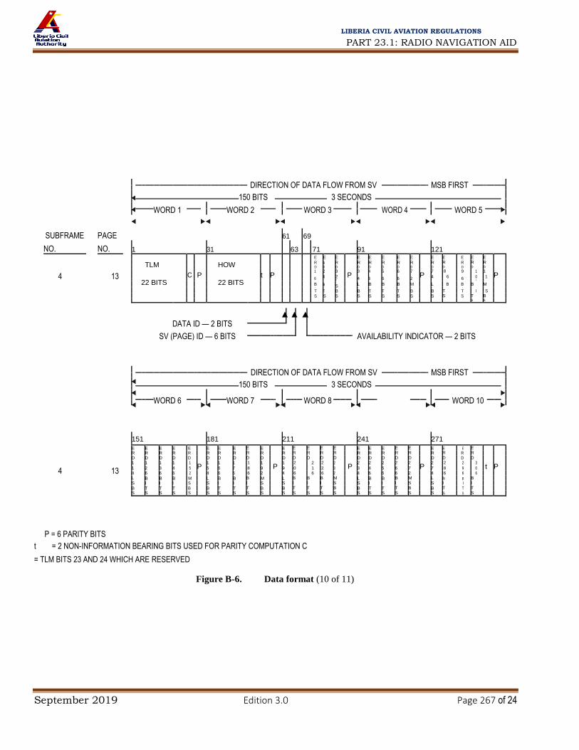
PART 23.1: RADIO NAVIGATION AID
September 2019 Edition 3.0 Page 267 of 24
LIBERIA CIVIL AVIATION REGULATIONS
DIRECTION OF DATA FLOW FROM SV
MSB FIRST
150 BITS 3 SECONDS
SUBFRAME
PAGE
WORD 1
WORD 2
WORD 3
WORD 4
WORD 5
61
69
NO. NO. 1 31 63 71 91 121
E E E E E E E E E E E E E
TLM HOW R R R R R R R R R R R R R
D D D D D D D D D D D D D
4 13
C
P
t P 1 2 3
P 3 4 5 6 7
P 7 8 9 1 1
P
22 BITS
22 BITS
6 6 2 4 6
6 6
2 4 6 6 0 1
M
L
B 6 2
B B S L B B B M B B M
I I S I I I S S I I
I
S
T T B B T T T B B T T
S S S S S S S S S S S T B
S S
DATA ID — 2 BITS
SV (PAGE) ID — 6 BITS
AVAILABILITY INDICATOR — 2 BITS
DIRECTION OF DATA FLOW FROM SV
MSB FIRST
150 BITS 3 SECONDS
WORD 6
WORD 7
WORD 8
WORD 10
181
241
271
151
211
E E E E E E E E E E E E E E E E E E E E E E E E
R R R R R R R R R R R R R R R R R R R R R R R R
D D D D D D D D D D D D D D D D D D D D D D D D
4 1 1 1 1 1
P 1 1 1 1 1
P 1 2 2 2 2
P 2 2 2 2 2
P 2 2 2 3
t P
13 1 2 3 4 5 5 6 7 8 9 9 0 1 2 3 3 4 5 6 7 7 8 9 0
4 6 6 6 2 4 6 6 6 2 4 6 6 6 2 4 6 6 6 2 4 6 6 6
L B B B M L B B B M L B B B M L B B B M L B B B
S I I I S S I I I S S I I I S S I I I S S I I I
B T T T B B T T T B B T T T B B T T T B B T T T
S S S S S S S S S S S S S S S S S S S S S S S S
P = 6 PARITY BITS
t = 2 NON-INFORMATION BEARING BITS USED FOR PARITY COMPUTATION C
= TLM BITS 23 AND 24 WHICH ARE RESERVED
Figure B-6. Data format (10 of 11)

PART 23.1: RADIO NAVIGATION AID
September 2019 Edition 3.0 Page 268 of 24
LIBERIA CIVIL AVIATION REGULATIONS
DIRECTION OF DATA FLOW FROM SV
MSB FIRST
150 BITS 3 SECONDS
WORD 1
WORD 2
WORD 3
WORD 4
WORD 5
SUBFRAME PAGE
61
NO. NO. 1 31 63 69 91 121
14, 15
TLM C P
HOW t P
16
P
24 BITS**
P
24 BITS** P
4
& 17**
22 BITS
22 BITS
BITS**
DATA ID — 2 BITS
SV (PAGE) ID — 6 BITS
DIRECTION OF DATA FLOW FROM SV
MSB FIRST
150 BITS
3 SECONDS
WORD 6
WORD 7
WORD 8
WORD 9
WORD 10
181
211
241
271
151
14, 15
4 24 BITS** P 24 BITS** P 24 BITS** P 24 BITS** P 22 BITS** t P
& 17**
** THE INDICATED PORTIONS OF WORDS 3 THROUGH 10 OF PAGES 14 AND 15 ARE RESERVED FOR SYSTEM USE, WHILE
THOSE OF PAGE 17 ARE RESERVED FOR SPECIAL MESSAGES
P = 6 PARITY BITS t = 2 NON-INFORMATION BEARING BITS USED FOR PARITY COMPUTATION C
= TLM BITS 23 AND 24 WHICH ARE RESERVED
Figure B-6. Data format (11 of 11)

PART 23.1: RADIO NAVIGATION AID
September 2019 Edition 3.0 Page 269 of 24
LIBERIA CIVIL AVIATION REGULATIONS
2 s
Frame number String number 1.7 s 0.3 s
1 0 Immediate data KX MB 2 0 for KX MB
3 0 transmitting KX MB 30 s
I 4 0 satellite KX MB •
Non-immediate data
•
(almanac)
•
for
15 0 five satellites KX MB
1 0 Immediate data KX MB
2 0 for KX MB
3 0 transmitting KX MB
II 4 0 satellite KX MB
•
Non-immediate data
• (almanac)
• for
15 0 five satellites KX MB
1 0 Immediate data KX MB
2 0 for KX MB
3 0 transmitting KX MB
III 4 0 satellite KX MB
•
Non-immediate data
• (almanac)
•
for
five satellites
15 0 KX MB
1 0 Immediate data KX MB
2 0 for KX MB
3 0 transmitting KX MB
IV 4 0 satellite KX MB
•
Non-immediate data
• (almanac)
• for
15 0 five satellites KX MB
1 0 Immediate data KX MB
2 0 for KX MB
3 0 transmitting KX MB
V 4 0 satellite KX MB
•
Non-immediate data
• (almanac)
• for
four satellites

PART 23.1: RADIO NAVIGATION AID
September 2019 Edition 3.0 Page 270 of 24
LIBERIA CIVIL AVIATION REGULATIONS
14 0 Reserved bits KX MB
15 0 Reserved bits KX MB
Bit number
84
85...............................9
8............1
Hamming code bits
within string
Data bits
in relative
in relative bi-binary code
bi-binary code

PART 23.1: RADIO NAVIGATION AID
September 2019 Edition 3.0 Page 271 of 24
LIBERIA CIVIL AVIATION REGULATIONS
Figure B-7. Superframe structure
17
/11
/112
3/1
1/0
6
No
. 86
AP
P B
-14
2

PART 23.1: RADIO NAVIGATION AID
September 2019 Edition 3.0 Page 272 of 24
LIBERIA CIVIL AVIATION REGULATIONS
String No.
1 4 2 2
tk 12
x ′(t ) 24
x ″(t ) 5
x (t ) 27 8
m
* P1
ΚΧ
ΜΒ
(P2) n b n b n b
4 3 1 tb
7 5 24 5 27 8
2 m Bn * y ′(t ) y ″(t ) y (t ) ΚΧ ΜΒ
n b n b n b
(P3) 3
4 1
γn(t b)
11 1 2 1 24 5 27 8
m * P 1n z n ′(t b) zn ″(t b) zn (t b) ΚΧ ΜΒ
4
τn(t b)
22 5 5 14 1 4 3
NT
11 5 2 8
4 m Δτn Εn * P4 FT * n M ΚΧ ΜΒ
4
NA
11
τc
32 1 N
4
5
τGPS
22 1
ΚΧ
8
ΜΒ
(Cn ) 5 m * 1n
6
4 1 2
nA
5
τΑ
λn
10
λΑn
21 iA
n
18
εAn
15
ΚΧ
8
ΜΒ
m MAn
7
4 16
τ Α 21
A
22 . A
7
A
5 1 ΚΧ
8 ΜΒ
m A 1n
ω n λ n ΔΤ n ΔΤ n Η n
1
nA 5
τΑ
λn
10
λΑn
21
iA
n
18
εAn
15
ΚΧ
8
ΜΒ
4 2
8 m MAn
.
7 5
4
ωAn
16
τλΑ
n
21
ΔΤAn
22 1 8
9 m ΔΤAn ΗA
n 1n ΚΧ ΜΒ
4 1 2
nA 5
τΑ
λ 10
λΑ 21
iA 18
εA 15
ΚΧ 8 ΜΒ
10 m MA
n n n n n
11 4 A 16 τ Α 21 A 22 . A 7 A 5 1 ΚΧ 8 ΜΒ
m ω n λ n ΔΤ n ΔΤ n Η
n 1n
12
1
nA 5
τΑ
λn 10
21
iAn
18
εAn
15
ΚΧ 8
ΜΒ
4 2
m MAn λΑ
n
. A 7
5
13
4 ω
A 16 τ Α 21 A 22 A 1 ΚΧ
8 ΜΒ
m
n λ n ΔΤ
n ΔΤ
n Η n 1n
n
14
1
nA
5
τΑ
λn
10
λΑn
21
iAn
18
εAn
15
ΚΧ
8
ΜΒ
4 2
m MAn
16
.
7
5
8
4 21
ΔΤAn
22 1
15 m ωAn τλ
Αn ΔΤA
n ΗAn 1n ΚΧ ΜΒ
* Reserved bits within frame Note.— Data content, definitions and explanations of parameters are given in 3.2.1.3 and 3.2.1.4. Additional data transmitted by GLONASS-M are highlighted in this
figure.
Figure B-8. Frame structure (frames 1 to 4)

PART 23.1: RADIO NAVIGATION AID
September 2019 Edition 3.0 Page 273 of 24
LIBERIA CIVIL AVIATION REGULATIONS
1
m 4 2 2
tk 12
x n′(t b) 24
x n″(t b) 5
x n (t b) 27 8
(P2) * P1 ΚΧ ΜΒ
2 m 4 Bn 3 1 tb 7 * 5 y n ′(t b) 24 y n ″(t b) 5 y n (t b) 27 ΚΧ 8 ΜΒ
(P3) 3
m
4 1
γn(tb)
11 1 2 1 24 5 27 8
* P 1n z n ′(t b) z n ″(t b) z n (t b) ΚΧ ΜΒ
4
τn (tb )
22 5 5 14 1 4 3 11 5 2 8
4 m Δτn Εn * P4 FT * NT n M ΚΧ ΜΒ
5
4
NA
11
τc
32 1 N
4
5
τGPS
22 1
ΚΧ
8
ΜΒ
(Cn ) m * 1n
6
4 1 2 5 10 21
iAn
18
εAn
15
ΚΧ
8
ΜΒ
m MAn nA τ
Αλn λΑ
n
7
m
4
ω
16
τ Α 21
A 22
. A 7
A 5 1
ΚΧ 8 ΜΒ
A 1n
n λ n ΔΤ n ΔΤ n Η n
4 1 2
nA
5 10
λΑn
21
iAn
18
εAn
15
ΚΧ
8
ΜΒ
8 m MAn τ
Αλn
. 7
5
4
ωAn
16
τλΑ
n
21
ΔΤAn
22
ΗAn
1 8
9 m ΔΤAn 1n ΚΧ ΜΒ
4 1 2 5 10 21
iA 18
εA 15
ΚΧ 8 ΜΒ
10 m MA nA τΑ
λ λΑ
n n n n n
16
. A 7
5
8
11 m
4 ω
A τ Α 21 A 22 A 1 1 ΚΧ ΜΒ
n λ n ΔΤ n ΔΤ n Η n n
12
4
1
nA 5
10
21
iA
18
εA
15
ΚΧ 8
ΜΒ
2
m MA τΑ
λ Α n
n n λ n n
. A 7
5
13
m 4
ω A 16 τ Α 21 A 22 A 1
ΚΧ 8
ΜΒ
n λ n ΔΤ n ΔΤ n Η n 1n
14 4 11 10 2
*
ΚΧ 8 ΜΒ
m
B1
B2
KP
15
4
*
1
ΚΧ
8
ΜΒ
m 1n
* Reserved bits within frame
Note.— Data content, definitions and explanations of parameters are given in 3.2.1.3 and 3.2.1.4. Additional data transmitted by GLONASS-M are highlighted in this
figure. Figure B-9. Frame structure (frame 5)

PART 23.1: RADIO NAVIGATION AID
September 2019 Edition 3.0 Page 274 of 24
LIBERIA CIVIL AVIATION REGULATIONS
2.0 s
1.7 s 0.3 s
Time mark
Data bits and check bits in bi-binary code (Tc = 10 ms)
(Tc = 10 ms)
1111100 ... 110
85 9 8 2 1
Data bits in relative bi-binary Hamming
code code check
bits (1–8) in relative
bi-binary code Character/numbers within string
Note.— Tc = time duration for each chip
Figure B-10. Data string structure
G4 (1011011)

PART 23.1: RADIO NAVIGATION AID
September 2019 Edition 3.0 Page 275 of 24
LIBERIA CIVIL AVIATION REGULATIONS
+ + + +
Data input Output symbols
500 symbols/s
(250 bits/s)
(Alternating G3/G4)
+ + + +
G3 (1111001)
Symbol
clock
Figure B-11. Convolutional encoding
DIRECTION OF DATA FLOW FROM SATELLITE; MOST SIGNIFICANT BIT (MSB) TRANSMITTED FIRST
250 BITS/SECOND 24-BIT
212-BIT DATA FIELD CRC
6-BIT MESSAGE TYPE IDENTIFIER (0–63)
8-BIT PREAMBLE OF 24 BITS TOTAL IN 3 CONTIGUOUS BLOCKS
Figure B-12. Data block format

PART 23.1: RADIO NAVIGATION AID
September 2019 Edition 3.0 Page 276 of 24
LIBERIA CIVIL AVIATION REGULATIONS
20

PART 23.1: RADIO NAVIGATION AID
September 2019 Edition 3.0 Page 277 of 24
LIBERIA CIVIL AVIATION REGULATIONS
-4.5 0
(1 315, -4.5) (2 000, -8.5)
(1 626.5, -22) with Satcom -8.5
-20
[dB
W]
-40 (1 500, -38) without Satcom
(1 618, -42)
Thr
esho
ld
(1 525, -42)
-60
(1 610, -60)
-80
Inte
rfer
ence
-100
-120
-140
(1 565.42, -150.5) (1 585.42, -150.5)
-160
1 300 1 400 1 500 1 600 1 700 1 800 1 900 2 000
Frequency [MHz]
Figure B-15. CW interference thresholds for GPS and SBAS receivers used for precision approach
20
-4.5
0
(1 315, -4.5) (2 000, -8.5) -8.5
(1 626.15625, -22) with Satcom
-20
[dB
W]
-40
without Satcom
(1 562.15625, -42)
(1 635.15625, -42)
Thr
esho
ld
-60
-80
(1 583.65625, -80)
(1 613.65625, -80)
Inte
rfer
ence
-100
-120
-140 (1 592.9525, -149) (1 609.36, -149)
-160
1 300 1 400 1 500 1 600 1 700 1 800 1 900 2 000
Frequency [MHz]
Figure B-16. CW interference thresholds for GLONASS receivers used for
precision approach

PART 23.1: RADIO NAVIGATION AID
September 2019 Edition 3.0 Page 278 of 24
LIBERIA CIVIL AVIATION REGULATIONS
–110
Terminal area, en-route and acquisition for all
Non-precision approach
–120
Precision approach and Satcom equipped –119.5
[d B
] W
–130
e
re
oldn
cTh
sh
–140
-140.5
I t e r e r e n f
–150 –150.5 3dB
6dB
–160
1
0.01 0.1 10 100 1 000 1·104 1·105
Interference Bandwidth (kHz)
Figure B-17. Interference thresholds versus bandwidth for
GPS and SBAS receivers

PART 23.1: RADIO NAVIGATION AID
September 2019 Edition 3.0 Page 279 of 24
LIBERIA CIVIL AVIATION REGULATIONS
Figure B-18. Interference thresholds versus bandwidth for
GLONASS

PART 23.1: RADIO NAVIGATION AID
September 2019 Edition 3.0 Page 280 of 24
LIBERIA CIVIL AVIATION REGULATIONS

PART 23.1: RADIO NAVIGATION AID
September 2019 Edition 3.0 Page 281 of 24
LIBERIA CIVIL AVIATION REGULATIONS
IS: 23.1.3.11 MICROWAVE LANDING SYSTEM (MLS) CHARACTERISTICS
Table A-1. Preamble timing*
(see Subpart 23.1.3.10.4.3.4)
Event time slot begins at
15.625 kHz Time Clock pulse
Event (number) (milliseconds)
Carrier acquisition (CW transmission) 0 0
Receiver reference time code I1= 1 13 0.832
I2= 1 1 0.896 I3= 1 15 0.960
I4= 0 16 1.024
I5= 1 17 1.088**
Function identification I6 18 1.152
I7 19 1.216 I8 20 1.280
I9 (see 3.11.4.4.3.3) 21 1.344
I10 22 1.408
I11 23 1.472
I
12 24 1.536 End preamble 25 1.600
* Applies to all functions transmitted. ** Reference time for receiver synchronization for all function timing.
Table A-2. Approach azimuth function timing (see 3.11.4.3.4)
Event time slot begins at
15.625 kHz Time
Clock pulse (number) (milliseconds)
Event
Preamble 0 0
Morse Code (see 3.11.4.6.2.1.2) 25 1.600
Antenna select 26 1.664
Rear OCI 32 2.048
Left OCI 34 2.176
Right OCI 36 2.304
TO test 38 2.432
TO scan* 40 2.560
Pause 8.760
Midscan point 9.060
FRO scan* 9.360

PART 23.1: RADIO NAVIGATION AID
September 2019 Edition 3.0 Page 282 of 24
LIBERIA CIVIL AVIATION REGULATIONS
FRO test 15.560
End function (airborne) 15.688
End guard time; end function (ground) 15.900
* The actual commencement and completion of the TO and FRO scan transmissions are dependent on the amount of proportional guidance
provided. The time slots provided will accommodate a maximum scan of plus or minus 62.0 degrees. Scan timing shall be compatible with accuracy
requirements.
Table A-3. High rate approach azimuth and back azimuth function timing (see 3.11.4.3.4)
Event time slot begins at
15.625 kHz Time
Clock pulse (number) (milliseconds)
Event
Preamble 0 0
Morse Code (see 3.11.4.6.2.1.2) 25 1.600
Antenna select 26 1.664
Rear OCI 32 2.048
Left OCI 34 2.176
Right OCI 36 2.304
TO test 38 2.432
TO scan* 40 2.560
Pause 6.760
Midscan point 7.060
FRO scan* 7.360
FRO test pulse 11.560
End function (airborne) 11.688
End guard time; end function (ground) 11.900
* The actual commencement and completion of the TO and FRO scan transmissions are dependent on the amount of proportional guidance
provided. The time slots provided will accommodate a maximum scan of plus or minus 42.0 degrees. Scan timing shall be compatible with accuracy
requirements.
Table A-4. Approach elevation function timing (see 3.11.4.3.4)
Event time slot begins at
15.625 kHz Time
Clock pulse (number) (milliseconds)
Event
Preamble 0 0
Processor pause 25 1.600
OCI 27 1.728
TO scan* 29 1.856
Pause 3.406
Midscan point 3.606
FRO scan* 3.806
End function (airborne) 5.356
End guard time; end function (ground) 5.600
* The actual commencement and completion of the TO and FRO scan transmissions are dependent on the amount of proportional guidance
provided. The time slots provided will accommodate a maximum scan of minus 1.5 degrees to plus 29.5 degrees. Scan timing shall be compatible
with accuracy requirements.

PART 23.1: RADIO NAVIGATION AID
September 2019 Edition 3.0 Page 283 of 24
LIBERIA CIVIL AVIATION REGULATIONS
Table A-5. Flare function timing (see 3.11.4.3.4)
Event time slot begins at
15.625 kHz Time
Clock pulse (number) (milliseconds)
Event
Preamble 0 0
Processor pause 25 1.600
TO scan* 29 1.856
Pause 3.056
Midscan point 3.456
FRO scan* 3.856
End function (airborne) 5.056
End guard time; end function (ground) 5.300
* The actual commencement and completion of the TO and FRO scan transmissions are dependent on the amount of proportional guidance
provided. The time slots provided will accommodate a maximum scan of minus 2.0 degrees to plus 10.0 degrees. Scan timing shall be compatible
with accuracy requirements.
Table A-6. Basic data function timing (see 3.11.4.3.4)
Event time slot begins at
15.625 kHz Time
Clock pulse (number) (milliseconds)
Event
Preamble 0 0
Data transmission (Bits I13 - I30) 24 1.600
Parity transmission (Bits I31 - I32) 43 2.752
End function (airborne) 45 2.880
End guard time; end function (ground) 3.100
Table A-7. Basic data (see 3.11.4.8.2.1)
Maximum time
between Least
Word Data content transmissions
Bits used Range of values significant bit Bit number
(seconds)
1 PREAMBLE 1.0 12 see Note 10 I
1 - I
12
Approach azimuth antenna to 6 0 m to 6 300 m 100 m I
13 - I
18
threshold distance I19
- I23
Approach azimuth proportional 5 0° to 60° 2°

PART 23.1: RADIO NAVIGATION AID
September 2019 Edition 3.0 Page 284 of 24
LIBERIA CIVIL AVIATION REGULATIONS
guidance sector negative limit (see Note 11)
Approach azimuth proportional 5 0° to 60° 2° I
24 - I
28
guidance sector positive limit (see Note 11)
Clearance signal type 1 see Note 9 I
29
SPARE 1 see Note 12 I
30
PARITY 2 see Note 1 I
31 - I
32
2 PREAMBLE 0.16 12 see Note 10 I1 - I12
Minimum glide path 7 2° to 14.7° 0.1° I
13 - I
19
Back azimuth status 1 see Note 2 I
20
DME status 2 see Note 7 I
21 - I
22
Approach azimuth status 1 see Note 2 I
23
Approach elevation status 1 see Note 2 I
24
SPARE 6 see Notes 6 and 12 I
25 - I
30
PARITY 2 see Note 1 I
31 - I
32
Maximum time between Least
Word Data content transmissions
Bits used Range of values significant bit Bit number
(seconds)
3 PREAMBLE 1.0 12 see Note 10 I1 - I12
Approach azimuth beamwidth 3 0.5° to 4° 0.5° I
13 - I
15
(See Note 8)
Approach elevation beamwidth 3 0.5° to 2.5° 0.5° I
16 - I
18
(See Note 8)
DME distance 9 0 m to 6 387.5 m 12.5 m I
19 - I
27
SPARE 3 see Note 12 I
28 - I
30
PARITY 2 see Note 1 I
31 - I
32
4 PREAMBLE 1.0 12 see Notes 4 and 10 I1 - I12
Approach azimuth magnetic 9 0° to 359° 1° I
13 - I
21
Orientation
Back azimuth magnetic orientation 9 0° to 359° 1° I
22 - I
30
PARITY 2 see Note 1 I
31 - I
32
5 PREAMBLE 1.0 12 see Notes 5 and 10 I1 - I12
Back azimuth proportional guidance 5 0° to 40° 2° I
13 - I
17

PART 23.1: RADIO NAVIGATION AID
September 2019 Edition 3.0 Page 285 of 24
LIBERIA CIVIL AVIATION REGULATIONS
sector negative limit (see Note 11)
Back azimuth proportional guidance 5 0° to 40° 2° I
18 - I
22
sector positive limit (see Note 11)
Back azimuth beamwidth 3 0.5° to 4.0° 0.5° I
23 - I
25 (see Note 8)
Back azimuth status 1 see Note 2 I
26
SPARE 4 see Notes 3 and 12 I
27 - I
30
PARITY 2 see Note 1 I
31 - I
32
6 PREAMBLE 1.0 12 see Notes 4 and 10 I
1 - I
12
MLS ground equipment Letters A to Z
Identification
Character 2 6 I
13 - I
18
Character 3 6 I
19 - I
24
Character 4 6 I
25 - I
30
PARITY 2 see Note 1 I
31 - I
32
NOTES.— 1. Parity bits I31 and I32 are chosen to satisfy the equations:
I13 + I14 ... + I29 + I30 + I31 = ODD I14 + I16 + I18 ... + I28 + I30 + I32 = ODD. 2. Coding for status bit: 0 = function not radiated, or radiated in test mode (not reliable for navigation); 1 = function radiated in normal mode (in Basic data word 2 the back azimuth status also indicates that back azimuth transmission is to follow). 3. These bits are reserved for future applications. One possible application is to define the back azimuth deviation scale factor. 4. Basic data words 4 and 6 are transmitted in both approach azimuth and back azimuth coverages if back azimuth guidance is provided, while retaining
the maximum specified time between transmissions in each coverage sector. 5. Basic data word 5 is transmitted in both approach azimuth and back azimuth coverages if back azimuth guidance is provided, while retaining the
maximum specified time between transmissions in each coverage sector. 6. These bits are reserved for future applications requiring high transmission rates. 7. Coding for I21 and I22:
I21 I22 0 0DME transponder inoperative or not available 1 0Only IA mode or DME/N available 0 1FA mode, Standard 1, available 1 1FA mode, Standard 2, available 8. The value coded is the actual beamwidth (as defined in Chapter 3, 3.11.1) rounded to the nearest 0.5 degree. 9. Code for I29 is: 0 = pulse clearance signal 1 = scanning clearance signal. 10. The 12 data bits of the preamble are preceded by an 0.832 millisecond interval (13 clock pulses) of CW for carrier acquisition (see Table A-1). 11. The scan limits are greater than the proportional guidance sector limits shown in Basic data words 1 and 5 as described in 3.11.4.5.1. 12. All spare bits are set to ZERO.
Table A-8. Auxiliary data function timing (see 3.11.4.3.4)

PART 23.1: RADIO NAVIGATION AID
September 2019 Edition 3.0 Page 286 of 24
LIBERIA CIVIL AVIATION REGULATIONS
Event time slot begins at
15.625 kHz Time Clock pulse
Event (number) (milliseconds)
Preamble 0 0 Address transmission (Bits I13 - I20) 25 1.600
Data transmission (Bits I21 - I69) 33 2.112
Parity transmission (Bits I70 - I76) 82 5.248 End function (airborne) 89 5.696
End guard time; end function (ground) 5.900
Table A-9. Auxiliary data words address codes
No. I13 I14 I15 I16 I17 I18 I19 I20 No. I13 I14 I15 I16 I17 I18 I19 I20
1 0 0 0 0 0 1 1 1 33 1 0 0 0 0 1 0 1 2 0 0 0 0 1 0 1 0 34 1 0 0 0 1 0 0 0 3 0 0 0 0 1 1 0 1 35 1 0 0 0 1 1 1 1 4 0 0 0 1 0 0 1 1 36 1 0 0 1 0 0 0 1 5 0 0 0 1 0 1 0 0 37 1 0 0 1 0 1 1 0 6 0 0 0 1 1 0 0 1 38 1 0 0 1 1 0 1 1 7 0 0 0 1 1 1 1 0 39 1 0 0 1 1 1 0 0 8 0 0 1 0 0 0 1 0 40 1 0 1 0 0 0 0 0 9 0 0 1 0 0 1 0 1 41 1 0 1 0 0 1 1 1
10 0 0 1 0 1 0 0 0 42 1 0 1 0 1 0 1 0 11 0 0 1 0 1 1 1 1 43 1 0 1 0 1 1 0 1 12 0 0 1 1 0 0 0 1 44 1 0 1 1 0 0 1 1 13 0 0 1 1 0 1 1 0 45 1 0 1 1 0 1 0 0 14 0 0 1 1 1 0 1 1 46 1 0 1 1 1 0 0 1 15 0 0 1 1 1 1 0 0 47 1 0 1 1 1 1 1 0 16 0 1 0 0 0 0 1 1 48 1 1 0 0 0 0 0 1 17 0 1 0 0 0 1 0 0 49 1 1 0 0 0 1 1 0 18 0 1 0 0 1 0 0 1 50 1 1 0 0 1 0 1 1 19 0 1 0 0 1 1 1 0 51 1 1 0 0 1 1 0 0 20 0 1 0 1 0 0 0 0 52 1 1 0 1 0 0 1 0 21 0 1 0 1 0 1 1 1 53 1 1 0 1 0 1 0 1 22 0 1 0 1 1 0 1 0 54 1 1 0 1 1 0 0 0 23 0 1 0 1 1 1 0 1 55 1 1 0 1 1 1 1 1 24 0 1 1 0 0 0 0 1 56 1 1 1 0 0 0 1 1 25 0 1 1 0 0 1 1 0 57 1 1 1 0 0 1 0 0 26 0 1 1 0 1 0 1 1 58 1 1 1 0 1 0 0 1 27 0 1 1 0 1 1 0 0 59 1 1 1 0 1 1 1 0 28 0 1 1 1 0 0 1 0 60 1 1 1 1 0 0 0 0 29 0 1 1 1 0 1 0 1 61 1 1 1 1 0 1 1 1 30 0 1 1 1 1 0 0 0 62 1 1 1 1 1 0 1 0 31 0 1 1 1 1 1 1 1 63 1 1 1 1 1 1 0 1 32 1 0 0 0 0 0 1 0 64 0 0 0 0 0 0 0 0
Note.— Parity bits I19 and I20 are chosen to satisfy the equations: I13 + I14 + I15 + I16 + I17 + I18 + I19 = EVEN I14 +
I16 + I18 + I20 = EVEN

PART 23.1: RADIO NAVIGATION AID
September 2019 Edition 3.0 Page 287 of 24
LIBERIA CIVIL AVIATION REGULATIONS
Table A-10. Auxiliary data (see 3.11.4.8.3.1)
Maximum time
Type of between Least
Word Data content data transmissions Bits Range of values significant Bit number
(seconds) used bit
A1 PREAMBLE digital 1.0 12 see Note 6 I1 - I12
Address 8 I
13 - I
20
Approach azimuth antenna offset 10 –511 m to +511 m 1 m 1
21 - I
30
(see Note 3)
Approach azimuth antenna to 13 0 m to 8 191 m 1 m I
31 - I
43
MLS datum point distance
Approach azimuth alignment with 12 –20.47° to +20.47° 0.01° I
44 - I
55
runway centre line (see Notes 3 and 7)
Approach azimuth antenna 1 See Note 2 I
56
coordinate system
Approach azimuth antenna height 7 –63 m to +63 m 1 m I
57 - I
63
(see Note 3)
SPARE 6 See Note 8 I
64 - I
69
PARITY 7 See Note 1 I
70 - I
76
A2 PREAMBLE digital 1.0 12 See Note 6 I1 - I12
Address 8 I
13 - I
20
Approach elevation antenna offset 10 –511 m to +511 m 1 m I
21 - I
30
(see Note 3)
MLS datum point to threshold 10 0 m to 1 023 m 1 m I
31 - I
40
distance
Approach elevation antenna height 7 –6.3 m to +6.3 m 0.1 m I
41 - I
47
(see Note 3)
MLS datum point elevation 13 –4 095 m to +4 095 m 1 m I
48 - I
60
(see Note 3)
Runway threshold height 7 –6.3 m to +6.3 m 0.1 m I
61 - I
67
(see Note 3)
SPARE 2 See Note 8 I
68 - I
69
PARITY 7 See Note 1 I
70 - I
76
A3 PREAMBLE (see Note 4) digital 1.0 12 See Note 6 I1 - I12
Address 8 I
13 - I
20
DME offset 12 –2 047 m to +2 047 m 1 m I
21 - I
32
(see Note 3)
DME to MLS datum point distance 14 –8 191 m to +8 191 m 1 m I
33 - I
46
(see Note 3)

PART 23.1: RADIO NAVIGATION AID
September 2019 Edition 3.0 Page 288 of 24
LIBERIA CIVIL AVIATION REGULATIONS
Maximum time
Type of data between Least
Word Data content transmissions Bits Range of values significant Bit number
(seconds) used bit
DME antenna height 7 –63 m to +63 m 1 m I
47 - I
53
(see Note 3)
Runway stop-end distance 14 0 m to 16 383 m 1 m I
54 - I
67
SPARE 2 See Note 8 I
68 - I
69
PARITY 7 See Note 1 I
70 - I
76
A4 PREAMBLE (see Note 5) digital 1.0 12 See Note 6 I1 - I12
Address 8 I
13 - I
20
Back azimuth antenna offset 10 –511 m to +511 m 1 m I21
- I30
(see Note 3)
Back azimuth to MLS datum 11 0 m to 2 047 m 1 m I
31 - I
41
point distance
Back azimuth alignment with 12 –20.47° to +20.47° 0.01° I
42 - I
53
runway centre line (see Notes 3 and 7)
Back azimuth antenna 1 See Note 2 I
54
coordinate system
Back azimuth antenna height 7 –63 m to +63 m 1 m I
55 - I
61
(see Note 3)
SPARE 8 See Note 8 I
62 - I
69
PARITY 7 See Note 1 I
70 - I
76
NOTES.— 1. Parity bits I70 to I76 are chosen to satisfy the equations which follow.
For bit I70 EVEN =(I13 + ... + I18) + I20 + I22 + I24 + I25 + I28 + I29 + I31 + I32 + I33 + I35 + I36 + I38 + I41 + I44 + I45 + I46 + I50 + (I52 + ... + I55) + I58 + I60 + I64 + I65
+ I70 For bit I71 EVEN =(I14 + ... + I19) + I21 + I23 + I25 + I26 + I29 + I30 + I32 + I33 + I34 + I36 + I37 + I39 + I42 + I45 + I46 + I47 + I51 + (I53 + ... + I56) + I59 + I61 + I65 + I66 + I71 For bit I72 EVEN =(I15 + ... + I20) + I22 + I24 + I26 + I27 + I30 + I31 + I33 + I34 + I35 + I37 + I38 + I40 + I43 + I46 + I47 + I48 + I52 + (I54 + ... + I57) + I60 + I62 + I66 + I67
+ I72 For bit I73 EVEN =(I16 + ... + I21) + I23 + I25 + I27 + I28 + I31 + I32 + I34 + I35 + I36 + I38 + I39 + I41 + I44 + I47 + I48 + I49 + I53 + (I55 + ... + I58) + I61 + I63 + I67 + I68 + I73 For bit I74 EVEN =(I17 + ... + I22) + I24 + I26 + I28 + I29 + I32 + I33 + I35 + I36 + I37 I39 + I40 + I42 + I45 + I48 + I49 + I50 + I54 + (I56 + ... + I59) + I62 + I64 + I68 + I69
+ I74 For bit I75 EVEN =(I13 + ... + I17) + I19 + I21 + I23 + I24 + I27 + I28 + I30 + I31 + I32 + I34 + I35 + I37 + I40 + I43 + I44 + I45 + I49 + (I51 + ... + I54) + I57 + I59 + I63 + I64 + I69 + I75 For bit I76 EVEN =I13 + I14 + ... + I75 + I76

PART 23.1: RADIO NAVIGATION AID
September 2019 Edition 3.0 Page 289 of 24
LIBERIA CIVIL AVIATION REGULATIONS
2. Code for antenna coordinate system is 0 = conical.
3. The convention for the coding of negative numbers is as
follows: MSB is the sign bit: 0 = positive 1 = negative Other bits represent the absolute value. The convention for the antenna location is as follows: As viewed from the MLS approach reference datum looking toward the MLS datum point, a positive number represents a location to the right of the
runway centre line (lateral offset) or above the runway (vertical offset), or towards the stop end of the runway (longitudinal distance). The convention for
the alignment is as follows: As viewed from above, a positive number represents clockwise rotation from the runway centre line to the respective zero-degree azimuth. 4. Data word A3 is transmitted in both approach azimuth and back azimuth coverages if back azimuth guidance is provided, while retaining the
maximum specified time between transmissions in each coverage sector. 5. Data word A4 is transmitted in both approach azimuth and back azimuth coverages if back azimuth guidance is provided, while retaining the
maximum specified time between transmissions in each coverage sector. 6. The 12 data bits of the preamble are preceded by an 0.832 millisecond interval (13 clock pulses) of CW for carrier acquisition (see Table A-1). 7. See Table A-12 for data words B42 and B43 which are defined for applications that require azimuth antenna rotation greater than the +20.47° supported
by the data items in A1, for azimuth, and A4, for back azimuth. At a facility with the approach azimuth rotation greater than +20.47°, B42 is transmitted in
place of A1. At a facility with the back azimuth rotation greater than +20.47°, B43 is transmitted in place of A4. 8. All spare bits are set to ZERO.
Table A-11. Definitions of auxiliary data B items (see 3.11.4.8.3.2)
Note.— Definitions of auxiliary data B items supporting MLS/RNAV procedures are shown in Table A-13.
a) Latitude of MLS datum point shall be the latitude coordinate of the MLS datum point as defined by the World
Geodetic System — 1984 (WGS-84) reference ellipsoid, coordinate system and associated datum.
b) Longitude of the MLS datum point shall be the longitude coordinate of the MLS datum point as defined by the
same reference ellipsoid, coordinate system, and datum noted in item a).
c) Vertical coordinate of the MLS datum point shall be the vertical coordinate of the MLS datum point as defined by
the same reference ellipsoid, coordinate system, and datum noted in item a).
Note.— Although WGS-84 has been approved as the ICAO Standard for geographical coordinates indicating latitude and
longitude, introduction of vertical WGS-84 coordinates is pending. Until this introduction, an elevation referenced to mean sea
level (msl) can continue to be used.
d) Approach azimuth true north orientation shall represent the angle measured in the horizontal plane clockwise from True
North to the zero-degree approach azimuth, originating from the approach azimuth antenna. The vertex of the measured angle
shall be the approach azimuth antenna phase centre.
e) Runway visual range (RVR) shall represent measurement of instrument RVR at touchdown zone, mid-point and stop
end of the runway together with the trend indication, provided in accordance with Annex 3, Chapter 4.
f) Surface wind shall represent wind speed and wind direction (magnetic), provided in accordance with Annex 3, Chapter 4.
g) Approach azimuth antenna offset shall represent the minimum distance between the approach azimuth antenna
phase centre and a vertical plane containing the runway centre line.

PART 23.1: RADIO NAVIGATION AID
September 2019 Edition 3.0 Page 290 of 24
LIBERIA CIVIL AVIATION REGULATIONS
h) Approach azimuth antenna to MLS datum point distance shall represent the minimum distance between the
approach azimuth antenna phase centre and the vertical plane perpendicular to the runway centre line and containing the
MLS datum point.
i) Approach azimuth alignment with runway centre line shall represent the minimum angle between the zero-degree
approach azimuth and the runway centre line. j) Approach azimuth antenna height shall represent the vertical location of the antenna phase centre with respect to the
MLS datum point. k) Back azimuth antenna offset shall represent the minimum distance between the back azimuth antenna phase centre and a
vertical plane containing the runway centre line. l) Back azimuth antenna to MLS datum point distance shall represent the minimum distance between the back azimuth
antenna and the vertical plane perpendicular to the runway centre line which contains the MLS datum point.
m) Back azimuth alignment with runway centre line shall represent the minimum angle between the zero-degree back
azimuth and the runway centre line. n) Back azimuth antenna height shall represent the vertical location of the antenna phase centre with respect to the MLS
datum point. o) Primary runway number shall represent the primary runway number as defined in Part 14, Section 14.5. p) Primary runway letter shall represent the primary runway letter as defined in Part 14, Section 14.5, where used to
differentiate between parallel runways. q) Secondary runway number shall represent the secondary runway number as defined in Part 14, subpart 14.5.
r) Secondary runway letter shall represent the secondary runway letter as defined in Part 14 Subpart 14.5, where used to
differentiate between parallel runways. s) Elevation guidance to secondary runway shall indicate whether or not elevation guidance may be used to the secondary
runway, and if so, whether it is directly usable as a raw angle or requires computed glide path.
t) Minimum glide path to secondary runway shall represent the lowest angle of descent along the secondary runway centre
line. u) Approach azimuth alignment with secondary runway centre line shall represent the minimum angle between the zero-
degree approach azimuth and the secondary runway centre line. v) Secondary runway threshold X coordinate shall represent the minimum distance between the secondary runway
threshold and the vertical plane perpendicular to the primary runway centre line containing the MLS datum point.
w) Secondary runway threshold Y coordinate shall represent the minimum distance between the secondary runway
threshold and the vertical plane containing the primary runway centre line.
x) Secondary runway threshold Z coordinate shall represent the height of the secondary runway threshold above the MLS
datum point. y) Secondary runway threshold crossing height shall represent the height above the secondary runway threshold at which
the computed glide path crosses the threshold.

PART 23.1: RADIO NAVIGATION AID
September 2019 Edition 3.0 Page 291 of 24
LIBERIA CIVIL AVIATION REGULATIONS
z) Virtual azimuth to secondary runway threshold distance shall represent the distance to the secondary runway threshold
from the point to be considered as the origin for lateral guidance to that runway. Note.— This distance may be used by the MLS receiver in a manner similar to the approach azimuth antenna to threshold
distance, to establish the lateral deviation scale factor.
Table A-12. Auxiliary data B
(see 3.11.4.8.3)
Maximum time
between Least Type of data transmissions Bits Bits used significant bit Bit number Word Data content (seconds) used
Words B1 through B39: Time-invariant (fixed) data items supporting MLS/RNAV procedures (see Table A-15) Words B40 through B54: Other fixed data items

PART 23.1: RADIO NAVIGATION AID
September 2019 Edition 3.0 Page 292 of 24
LIBERIA CIVIL AVIATION REGULATIONS
Maximum time between Least
Type of transmissions Bits Bits significant Bit Word Data content data (seconds) used used bit number
PARITY 7 see Note 1 I70 - I76
B43 PREAMBLE (see Notes 4 and 5) digital 1.0 12 see Note 6 I1 - I12
Address 8 I13 - I20
Back azimuth antenna offset 10 –511 m to +511 m 1 m I21 - I30
(see Note 2)
Back azimuth antenna to MLS 11 0 m to 2 047 m 1 m I31 - I41
datum point distance
Back azimuth alignment with 14 –81.91° to +81.91° 0.01° I42 - I55
runway centre line (see Note 2)
Back azimuth antenna height 7 –63 m to +63 m 1 m I56 - I62
(see Note 2)
SPARE 7 see Note 9 I63 - I69
PARITY 7 see Note 1 I70 - I76
B44 PREAMBLE digital 2.0 12 see Note 6 I1 - I12
Address 8 I13 - I20
Primary runway number 6 0 to 36 I21 - I26
(see Note 10)
Primary runway letter 2 see Note 7 I27 - I28
Secondary runway number 6 0 to 36 I29 - I34
(see Note 10)
Secondary runway letter 2 see Note 7 I35 - I36
Elevation guidance to 2 see Note 8 I37 - I38
secondary runway
Minimum glide path to 7 2° to 14.7° 0.1° I39 - I45 secondary runway
Approach azimuth alignment with 16 ±180.00° 0.01° I46 - I61
secondary runway centre line
SPARE 8 see Note 9 I62 - I69
PARITY 7 see Note 1 I70 - I76
B45 PREAMBLE digital 2.0 12 see Note 6 I1 - I12
Address 8 I13 - I20
Secondary runway threshold 15 ±16 384 m 1 m I21 - I35 X coordinate

PART 23.1: RADIO NAVIGATION AID
September 2019 Edition 3.0 Page 293 of 24
LIBERIA CIVIL AVIATION REGULATIONS
Secondary runway threshold 15 ±16 384 m 1 m I36- I50
Y coordinate
Maximum time
between Least
Type of data transmissions Bits Bits used significant bit Bit number Word Data content (seconds) used
Secondary runway threshold 8 ±127 m 1 m I
51 - I
58
Z coordinate
Secondary runway threshold 5 0 to 31 m 1 m I
59 - I
63
crossing height
Virtual azimuth to secondary runway 6 0 to 6 300 m 100 m I64 - I69 threshold distance
PARITY 7 see Note 1 I70 - I76
Words B55 through B64: Time-varying data items. (Note.— Word B55 only is defined below.)
B55PREAMBLE digital 10.0 12 see Note 6 I1 - I12
Address 8 I
13 - I
20
RVR (touchdown zone) 11 0 - 2 555 m 5 m I
21 - I
31 (see Note 3)
RVR (mid-point) 11 0 - 2 555 m 5 m I
32 - I
42
(see Note 3)
RVR (stop end) 11 0 - 2 555 m 5 m I
43 - I
53
(see Note 3)
Surface wind speed 7 0 - 127 kt 1 kt I
54 - I
60
Surface wind direction (magnetic) 9 0 - 359° 1° I
61 - I
69
PARITY 7 see Note 1
I70
- I76
NOTES.— 1. Parity bits I70 to I76 are chosen to satisfy the equations which follow.
For bit I70
EVEN = (I13 + ... + I18) + I20 + I22 + I24 + I25 + I28 + I29 + I31 + I32 + I33 + I35 + I36 +
I38 + I41 + I44 + I45 + I46 + I50 + (I52 + ... + I55) + I58 + I60 + I64 + I65 + I70
For bit I71
EVEN = (I14 + ... + I19) + I21 + I23 + I25 + I26 + I29 + I30 + I32 + I33 + I34 + I36 + I37 +
I39 + I42 + I45 + I46 + I47 + I51 + (I53 + ... + I56) + I59 + I61 + I65 + I66 + I71
For bit I72
EVEN = (I15 + ... + I20) + I22 + I24 + I26 + I27 + I30 + I31 + I33 + I34 + I35 + I37 + I38 +
I40 + I43 + I46 + I47 + I48 + I52 + (I54 + ... + I57) + I60 + I62 + I66 + I67 + I72
For bit I73
EVEN = (I16 + ... + I21) + I23 + I25 + I27 + I28 + I31 + I32 + I34 + I35 + I36 + I38 + I39 +
I41 + I44 + I47 + I48 + I49 + I53 + (I55 + ... + I58) + I61 + I63 + I67 + I68 + I73
For bit I74
EVEN = (I17 + ... + I22) + I24 + I26 + I28 + I29 + I32 + I33 + I35 + I36 + I37 + I39 + I40 +
I42 + I45 + I48 + I49 + I50 + I54 + (I56 + ... + I59) + I62 + I64 + I68 + I69 + I74
For bit I75

PART 23.1: RADIO NAVIGATION AID
September 2019 Edition 3.0 Page 294 of 24
LIBERIA CIVIL AVIATION REGULATIONS
EVEN = (I13 + ... + I17) + I19 + I21 + I23 + I24 + I27 + I28 + I30 + I31 + I32 + I34 + I35 + I37 +
I40 + I43 + I44 + I45 + I49 + (I51 + ... + I54) + I57 + I59 + I63 + I64 + I69 + I75
For bit I76 EVEN = I13 + I14 + ... + I75 + I76
2. The convention for the coding of negative numbers is as follows:
MSB is the sign bit:
0 = positive 1 = negative
Other bits represent the absolute value. The convention for the antenna location is as follows: As viewed from the MLS approach reference datum looking toward the MLS datum point, a positive number represents a location to the right of the
runway centre line (lateral offset) or above the runway (vertical offset), or towards the stop end of the runway (longitudinal distance). The convention for the alignment is as follows: As viewed from above, a positive number represents clockwise rotation from the runway centre line to the respective zero-degree guidance radial.
The convention for geodetic coordinates is as follows: A positive number represents a northern latitude or eastern longitude. A negative number represents a southern latitude or western longitude.
3. The tenth and eleventh bits transmitted for each RVR value are used to provide trend information. The convention for coding is as follows:
Tenth bit Eleventh bit
Off 0 0 Decreasing 1 0 Equal 0 1 Increasing 1 1
4. When used, data word B43 is transmitted in both approach azimuth and back azimuth coverage sectors if back azimuth guidance is provided, while
retaining the specified maximum time between transmissions in each area. 5. Data words B42 and B43 are defined for applications that require azimuth antenna rotation greater than the 20.47° supported by the data items in A1, for
azimuth, and A4, for back azimuth. At a facility with approach azimuth rotation greater than 20.47°, B42 is transmitted in place of A1. At a facility with the
back azimuth rotation greater than 20.47°, B43 is transmitted in place of A4. 6. The 12 data bits of the preamble are preceded by an 0.832 millisecond interval (13 clock pulses) of CW for carrier acquisition (see Table A-1). 7. The convention for coding is as follows:
0 = no letter 1 = R (right) 2 = C (centre) 3 = L (left)
8. The convention for coding is as follows:
0 = not provided
1 = raw elevation guidance 2 = computed glide path 3 = code not allowed
9. All spare bits are set to ZERO. 10. Runway number designation 0 is for heliport operations.
Table A-13. Definitions of auxiliary data B items concerning MLS/RNAV procedure database
(see 3.11.4.8.3.2)
a) Number of approach azimuth procedure descriptors shall represent the total number of named approach and
departure procedures for which procedure descriptor words are transmitted in the approach azimuth coverage sector.
Note.— Missed approaches are not counted, as they do not use procedure descriptor words. Computed centre line procedures
to the primary runway are counted if a procedure descriptor is transmitted, even though associated waypoint data are not
transmitted in auxiliary words B1 to B39.

PART 23.1: RADIO NAVIGATION AID
September 2019 Edition 3.0 Page 295 of 24
LIBERIA CIVIL AVIATION REGULATIONS
b) Number of back azimuth procedure descriptors shall represent the total number of named approach and
departure procedures for which procedure descriptor words are transmitted in the back azimuth coverage sector.
Note.— Missed approaches are not counted, as they do not use procedure descriptor words.
c) Last approach azimuth database word shall represent the address code of the last auxiliary data word within the range B1
to B39 which is transmitted in the approach azimuth coverage sector, as defined by bits I13 to I18 of that word.
d) First back azimuth database word shall represent the address code of the first auxiliary data word within the range B1
to B39 which is transmitted in the back azimuth coverage sector, as defined by bits I13 to I18 of that word.
e) Approach azimuth CRC code shall represent the coefficients of the cyclic redundancy check code for the
approach azimuth procedure database.
f) Back azimuth CRC code shall represent the coefficients of the cyclic redundancy check code for the back
azimuth procedure database.
g) Word B42 transmitted shall indicate whether auxiliary data word B42 is transmitted in lieu of word A1.
h) Word A4 transmitted shall indicate whether auxiliary data word A4 is transmitted.
i) Word B43 transmitted shall indicate whether auxiliary data word B43 is transmitted.
j) Back azimuth map/CRC indicator shall indicate whether auxiliary data word B39 is employed as a back
azimuth map/CRC word or as an approach azimuth waypoint data word.
k) Basic indicator shall represent the name of the first flown waypoint in an approach procedure, or the last flown
waypoint in a departure procedure. The name shall consist of five alpha characters coded in accordance with bits b1 to b5 of
International Alphabet No. 5.
l) Validity indicator shall represent the revision level of the approach or departure procedure. The validity indicator shall
be a number from 1 to 9.
m) Route indicator shall represent the route to or from the waypoint named by the basic indicator. The route indicator
shall be a single alpha character coded in accordance with bits b1 to b5 of International Alphabet No. 5. The letters “I”
and “O” shall not be used. Each of the 24 available route indicators shall be assigned not more than once within the
combined set of approach azimuth and back azimuth procedure descriptor words.
Note.— The restriction on the unique assignment of route indicators for MLS/RNAV operations is a departure from normal
route assignment practice necessary to enhance the integrity of procedure selection and reduce pilot workload.
n) Runway number shall represent the runway number as defined in Annex 14, Volume I, Chapter 5.
o) Runway letter shall represent the runway letter as defined in Annex 14, Volume I, Chapter 5, where used to differentiate
between parallel runways.
p) Procedure type shall indicate whether the procedure is an approach procedure or a departure procedure.
q) First waypoint index shall represent the sequential position, within the approach azimuth database or back azimuth
database, of the waypoint definition data for the first encoded waypoint of the procedure.
r) X coordinate shall represent the X coordinate of a given waypoint in the coordinate system defined.

PART 23.1: RADIO NAVIGATION AID
September 2019 Edition 3.0 Page 296 of 24
LIBERIA CIVIL AVIATION REGULATIONS
s) Y coordinate follows shall indicate whether or not the Y coordinate is transmitted for a given waypoint. If the Y coordinate
is not transmitted, the Y coordinate is assumed to be zero.
t) Y coordinate shall represent the Y coordinate of a given waypoint in the coordinate system defined.
u) Z coordinate follows shall indicate whether or not the Z coordinate is transmitted for a given waypoint.
v) Z coordinate shall represent the Z coordinate of given waypoint in the coordinate system defined.
w) Next segment/field identifier shall indicate whether the next segment of a given procedure is straight or curved and
indicate which data fields follow the waypoint coordinates.
x) Threshold waypoint height shall represent the height of the primary runway threshold waypoint above the runway
threshold.
y) Virtual azimuth to waypoint distance shall represent the distance to the waypoint from the point to be considered as the
origin for lateral guidance for an approach procedure not leading to the primary runway threshold.
Note.— This distance may be used by the MLS receiver in a manner similar to the approach azimuth antenna to
threshold distance, to establish the lateral deviation scale factor for the procedure.
z) Next waypoint index shall represent the sequential position, within the approach azimuth database or back azimuth
database, of the waypoint definition data for the next waypoint in the procedure.
Note.— The next waypoint index may be used to permit sharing of one or more waypoints which have been explicitly defined as
a part of another procedure. The shared waypoints are the final ones for approach procedures and the initial ones for missed
approach and departure procedures.
aa) Missed approach index shall represent the sequential position, within the approach azimuth database or back azimuth
database, of the waypoint definition data for the first encoded (last flown) waypoint of the associated missed approach procedure.
Table A-14. MLS/RNAV procedure database structure (see 3.11.4.8.3.2)
Database Word Data content
B1 B2 Approach azimuth map/CRC word
. . . Procedure 1 descriptor word
Approach azimuth . . . B(M+1) . . .
B(M+2) to B(a) . . .
Procedure “M” descriptor word (see Note 1)
Waypoint data words
B(a+1) to B(b–1) Not used.
B(b) Procedure 1 descriptor word
. . . . . .
Back azimuth . . . . . .
(see Note 2) B(b+N–1) Procedure “N” descriptor word (see Note 1)
B(b+N) to B(38) Waypoint data words
B39 Back azimuth map/CRC word

PART 23.1: RADIO NAVIGATION AID
September 2019 Edition 3.0 Page 297 of 24
LIBERIA CIVIL AVIATION REGULATIONS
NOTES.— 1. Parameter “M” represents the number of named approach and departure procedures which commence within the approach
azimuth coverage sector. Parameter “N” represents the number of named approach and departure procedures which commence within the
back azimuth coverage sector. A facility without a back azimuth database may employ all words up to B39 for the approach azimuth database.
Table A-15. Auxiliary data B words B1 through B39 (see 3.11.4.8.3.2)
Type of Maximum Range of values
Word Data content data time Bits Bit numbers
(seconds) used
Approach azimuth map/CRC word
B1 PREAMBLE digital 2.5 12 I1 to I12
Address 8 I13 to I20
Number of approach azimuth 4 0 to 15 I21 to I24
procedure descriptors
Last approach azimuth database word 6 see Note 2 I25 to I30
Approach azimuth CRC code 32 see Note 3 I31 to I62
Word B42 transmitted 1 see Note 4 I
63
Word A4 transmitted 1 see Note 4 I
64
Word B43 transmitted 1 see Note 4 I
65
Spare 4 see Note 12 I66 to I69
PARITY 7 see Note 13 I70 to I76
Type Maximum Range
of time Bits of Bit Word Data content data (seconds) used values numbers
Procedure descriptor words
B2 to B(M+1) (approach azimuth database) (see Note 1) B(b) to B(b+N–1) (back azimuth database)
PREAMBLE digital 2.5 12 I1 to I12
Address 8 I13 to I20
Basic indicator 25 see Note 5 I21 to I45
Validity indicator 4 1 to 9 I
46 to I
49 (see Note 14)
Route indicator 5 see Note 5 I50 to I54
Runway number 6 0 to 36 I55 to I60 (see Note 15)
Runway letter 2 see Note 6 I61 to I62
Procedure type 1 see Note 7 I
63
First waypoint index 6 0 to 63 I64 to I69 (see Notes 8, 9)
PARITY 7 see Note 13 I70 to I76

PART 23.1: RADIO NAVIGATION AID
September 2019 Edition 3.0 Page 298 of 24
LIBERIA CIVIL AVIATION REGULATIONS
Waypoint data words (see Table A-16)
B(M+2) to B(a) (approach azimuth database) (see Notes 1 and 11) B(b+N) to B(38) (back azimuth database)
PREAMBLE digital 2.5 12 I1 to I12
Address 8 I13 to I20
Waypoint definition data items 49 see Notes 10, 11 I21 to I69
PARITY 7 see Note 13 I70 to I76
Back azimuth map/CRC word (see Notes 1 and 11)
B39 PREAMBLE digital 2.5 12 I1 to I12
Address 8 I13 to I20
Number of back azimuth procedure 4 0 to 15 I21 to I24 descriptors
First back azimuth database word 6 see Note 2 I25 to I30
Back azimuth CRC code 32 see Note 3 I31 to I62
Word B43 transmitted 1 see Note 4 I
63
Spare 5 see Note 12 I64 to I68
Back azimuth map/CRC indicator 1 see Note 11 I
69
PARITY 7 see Note 13 I70 to I76
NOTES.— 1. Variables used in word numbers correspond to those used in Table A-14. 2. This field is coded in accordance with Table A-9, using bits I13 through I18. In this table, bit I25 carries the information of bit I13 from Table A-9 and is
transmitted first.
3. The CRC code contains the remainder, R(x), of the modulo 2 division of two polynomials:
x32
M (x) = Q(x) + R(x)
G(x) G(x)
mod 2
M(x) is the information field, which consists of the approach azimuth or back azimuth database defined below, excluding the preambles, addresses, parity
bits, and CRC code bits. For auxiliary data words these are bits I21 to I69, and for basic data words bits I13 to I30. The database consists of the following
data words in the order listed:
Approach azimuth database: Back azimuth database: B1 (bits I21 to I30, I63 to I69) B(b) to B38 B2 to B(a) B39 (bits I21 to I30, I63 to I69) B40, B41 B40, B41, A3 A1 or B42, A2, A3 A4 or B43 (if transmitted) A4 or B43 (if transmitted) Basic data word 6 Basic data word 6

PART 23.1: RADIO NAVIGATION AID
September 2019 Edition 3.0 Page 299 of 24
LIBERIA CIVIL AVIATION REGULATIONS
M(x) is multiplied by x32, which appends 32 zero bits to the end of the dividend. G(x) is the generator polynomial, defined as follows:
G(x) = x32 + x31 + x14 + x13 + x9 + x8 + x4 + x3 + x + 1 Q(x) is the quotient of the division. The CRC code, R(x), is transmitted with the coefficient of x31 as bit I31 and the coefficient of x0 as bit I62.
4. The convention for coding is as follows: 0 = no 1 = yes 5. Alpha characters are coded as defined in 3.11.4.8.3 for data words B1 through B39. 6. The convention for coding is as follows: 0 = no letter 1 = R (right) 2 = C (centre) 3 = L (left) 7. The convention for coding is as follows: 0 = approach procedure 1 = departure procedure 8. Waypoint index numbers are assigned by sequentially numbering all waypoints in the approach azimuth or back azimuth database. If a waypoint at the
primary runway threshold is coded using only a threshold crossing height, it is omitted from the waypoint index sequence.
9. A value of zero in this field indicates that the procedure is a computed centre line procedure based on data contained in auxiliary data words A1 (or B42),
A2, A3 and A4 (or B43).
10. Waypoint definitions are of variable length and are coded sequentially without conforming to word boundaries. Spare bits are not permitted between
waypoint definitions. Any spare bits at the end of the last waypoint data word are set to zero. Waypoint definitions for an approach procedure are coded in the
order that the aircraft flies the procedure. Waypoint definitions for a missed approach or departure are coded in the reverse order. Missed approach or departure
waypoints which are not shared with approach waypoints are coded after the last approach waypoint in the database. 11. A facility without a back azimuth data base may employ auxiliary word B39 as a waypoint data word for the approach azimuth database. Bit I69 of word
B39 is used to indicate the application of this word. The convention for coding is as follows: 0 = word B39 is a waypoint data word 1 = word B39 is the back azimuth map/CRC word
12. All spare bits are set to ZERO.
13. Parity bits I70 to I76 are chosen to satisfy the equations given in Note 1 of Table A-12. 14. The coded value 0000 is not allowed.
15. Runway number designation 0 is for heliport operations.
Table A-16. Waypoint definition data items (see 3.11.4.8.3.2)
Range Least Bits of significant Data content used values bit
X coordinate 15 ±41 940 m 2.56 m
(see Notes 1, 2)
Y coordinate follows 1 See Note 3
Y coordinate 15 ±41 940 m 2.56 m
(see Notes 1, 2)
Z coordinate follows 1 See Note 3
Z coordinate 13 –100 to +8 091 m 1 m
(see Notes 1, 4)
Next segment/field identifier 3 See Note 5
Threshold waypoint height 6 0 to 31.5 m 0.5 m
(see Note 5)
Virtual azimuth to waypoint distance 6 0 to 6 300 m 100 m
(see Note 5)
Next waypoint index 6 See Notes 5, 6

PART 23.1: RADIO NAVIGATION AID
September 2019 Edition 3.0 Page 300 of 24
LIBERIA CIVIL AVIATION REGULATIONS
Missed approach index 6 See Notes 5, 6
NOTES.—
1. The origin of the coordinate system is the MLS datum point. The X-axis is horizontal, and lies in the vertical plane
containing the runway centre line, with a positive number representing a location toward the approach reference datum. The Y-axis is horizontal
and perpendicular to the X-axis, with a positive number representing a location to the left of centre line as viewed from the MLS datum point
looking toward the approach reference datum. The Z-axis is vertical, with a positive number representing a location above the MLS datum
point. Earth curvature is not considered when determining waypoint coordinate values. 2. The convention for coding is as follows:
Most significant bit is the sign bit: 0 = positive 1 = negative
The other bits represent the absolute value. 3. The convention for coding is as follows:
0 = no 1 = yes
The “Y coordinate follows” bit is set to ZERO (no) to indicate that the Y coordinate for the waypoint is zero. In this
case, the Y coordinate field is not used. The “Z coordinate follows” bit is set to ZERO (no) to indicate either that the
waypoint is two-dimensional or that it lies on a constant gradient between two waypoints for which the Z coordinate is
transmitted. In either of these two cases, the Z coordinate field is not used. 4. This field is coded as an unsigned value with an offset of –100 m. A value of zero in this field would therefore
represent a Z coordinate of –100 m.
5. Data fields which follow the next segment/field identifier are transmitted only for certain cases. The coding of the next
segment/field identifier and use of subsequent data fields are defined in Table A-17.
6. Waypoint index numbers are assigned by sequentially numbering all waypoints in the approach azimuth or back azimuth
database. If a waypoint at the primary runway threshold is coded using only a threshold crossing height, it is omitted from the waypoint index
sequence. The next waypoint index field always refers to an index number lower than that of the current waypoint. The missed approach index
field always refers to an index number higher than that of the current waypoint.
Table A-17. Next segment/field identifiers
(see 3.11.4.8.3.2)
Application Data field(s) to follow identifier
Next
Next
Next waypoint Linked to segment/
waypoint shared missed Segment field Approach Missed approach Departure
location (Note 1) approach type identifier procedure procedure procedure
No
Straight 0 Next waypoint X coordinate
Any No Curved 1
Yes Straight 2
1. Next waypoint index
Curved 3
2. Next procedure first waypoint X coordinate
1. Threshold waypoint height Next procedure first waypoint
No
4 2. Next procedure first way-
X coordinate
Primary
point X coordinate
Straight
runway 1. Threshold waypoint height
threshold
Yes
5 2. Missed approach index Not allowed
3. Next procedure first way- (see Note 3)
point X coordinate
No None
1. Virtual azimuth to waypoint
distance Next procedure first waypoint
No (see Note
2. Next procedure first way- X coordinate
2) 6
point X coordinate
None
Straight to 1.Virtual azimuth to waypoint

PART 23.1: RADIO NAVIGATION AID
September 2019 Edition 3.0 Page 301 of 24
LIBERIA CIVIL AVIATION REGULATIONS
first flown distance
Not allowed
Yes missed 7
2. Missed approach index
(see Note 3)
approach 3. Next procedure first way-
waypoint point X coordinate
NOTES.—
1. A shared waypoint is a waypoint that is identified in the current procedure by waypoint index number only. The waypoint coordinates are explicitly
defined as part of another procedure. 2. Beyond this waypoint, guidance information is provided relative to the straight line extended from the current waypoint, tangent to the path entering
the waypoint. In the case of a missed approach procedure, this line intersects the last approach waypoint.
3. Next segment/field identifier values 5 and 7 are reserved for use in approach procedures only. Missed approach and departure procedures may share
approach waypoints which use these values, ignoring the data fields for threshold waypoint height, virtual azimuth to threshold distance and missed approach
index.

PART 23.1: RADIO NAVIGATION AID
September 2019 Edition 3.0 Page 302 of 24
LIBERIA CIVIL AVIATION REGULATIONS

PART 23.1: RADIO NAVIGATION AID
September 2019 Edition 3.0 Page 303 of 24
LIBERIA CIVIL AVIATION REGULATIONS

PART 23.1: RADIO NAVIGATION AID
September 2019 Edition 3.0 Page 304 of 24
LIBERIA CIVIL AVIATION REGULATIONS