Embed Size (px)
Citation preview
International Journal of Computer Applications (0975 – 8887)
Volume 146 – No.15, July 2016
5
Li-Fi (Light Fidelity)
K. Lakshmisudha Associate Professor Dept. of Information
Technology, SIES GST Nerul(E).
Divya Nair BE-IT
SIES GST Nerul(E),
Aishwarya Nair BE-IT
SIES GST Nerul(E),
Pragya Garg BE-IT
SIES GST, Nerul(E),
ABSTRACT
A person gets frustrated when he faces slow speed as many
devices are connected to the same network. As the number of
people accessing wireless internet increases, it’s going to
result in clogged airwaves. Li-Fi is transmission of data
through illumination by taking the fiber out of fiber optics by
sending data through a LED light bulb that varies in intensity
faster than the human eye can follow.
As Li-Fi is considered to be the optical version of Wi-Fi,
some label it as fast and cheap wireless communication
system. When LED is on digital 1 is transmitted and when it
is off 0 is transmitted. Data can be encoded in the light by
varying the flickering rate to generate strings of 1s and 0s.
The output appears to be constant to the human eye as the
LED intensity is modulated rapidly.
This method of using rapid pulses of light to transmit
information wirelessly is technically referred to as Visible
Light Communication (VLC). Advancements promise a speed
of 10 Gbps. Li-Fi can work even underwater.
If this technology can be put into practical use, every bulb can be used something like a Wi-Fi hotspot to transmit wireless data and will proceed toward a cleaner, greener, safer and brighter future. As the growing number of device accessing wireless internet are coming into use airwaves are becoming increasingly clogged making it more and more difficult to get a reliable, high speed signal. General Terms LED light source, VLC, Transmission
Keywords
Photodiode, Microcontroller
1. INTRODUCTION Li-Fi is the term used to label the wireless communication
system through an optical source that makes the system fast
and cheap. Li-Fi is based upon Visible Light Communication
technology where data transmission is made through a light
bulb whose intensity varies at a rate faster than the human eye
can follow. The fiber out of the fiber optics is replaced by an
LED source for the data transmission. The term Li-Fi was
introduced by Harald Hass in his TED Global talk on Visible
Light Communication “At the heart of this technology is a
new generation of high brightness light-emitting diodes”,
Hass says. Hass also included the transmission process as
“Very simply, if the LED is on, a digital 1 is transmitted, if
it’s off 0 is transmitted. They can be switched on and off very
quickly, which gives nice opportunities for transmitted data.”
The data to be transmitted is first encoded in to the light
through varying the rate of flickering that generates different
strings of 1’s and 0’s. Generally the modulation rate of LED is
so rapid that the human eye cannot detect the variation and the
output is generated continuously.
Li-Fi was mainly designed to overcome the drawbacks of Wi-
Fi usage. White LED is expected to replace fluorescent and
incandescent lights in future and can be regarded as text
generation lighting source. LED can support high speed on
and off which can help in acquiring high data rate. Since in
case of Li-Fi system optical source of light been used as a data
transfer medium it can be safely used at the places where
radio waves can harm the environment. Hospitals and Aircraft
that are prone to the interference made by the radio waves can
now make use of LED light as a safe mode of data
transmission with no interference of waves. Unlike the Wi-Fi
system, Li-Fi can be used in under water environment which
increases the scope to be used in military operations.
2. RELATED WORK Notable work has been done by WANG Jia-yuan, ZOU
and group mates in [1]. In the paper Experimental study
on visible light communication based on LED paper they
have talked about the data rate of LI-Fi i.e. 111.607 kbps
and communication distance i.e. 1.5m. Also it is known
that Li-Fi is based on VLC through the paper.
In 2012, the paper published by Jyoti Rani and
teammates was Li-Fi- The future technology in wireless
communication [2]. Through this paper it is understood
that transmission is done by taking fibre out of fibre
optics and data is sent through LED light.
In 2014, Navyatha’s group published the paper Li-Fi-Led
based alternatives [3]. Parallel data transmission is done
by using any spectrum of light like red, green, blue.
Raunak and group published the paper Li-Fi technology
[4]. Due to the low cost nature of LEDs and lighting
units, there are many opportunities to exploit from public
internet access through street lamps to auto- piloted cars.
In the paper Li-Fi: A Reconnaissance of future
technology [5]. Li-Fi includes sub-gigabit, gigabit- class
communication speeds for short, medium and long
ranges.
Another paper published in 2014 by was by Vitthal and
group by name of Next of Wi-Fi - a future technology in
Wireless Networking Li-fi using LED over Internet of
Things [6]. Li-Fi idea is same as that of infrared remote
controls but is more powerful hence called D-LIGHT.
In 2015, Gagandeep Kaur Virk published the paper Li-fi:
A New Communication Mechanism [7]. Li-Fi is more
secure as light waves cannot penetrate through walls and
cannot be intercepted by anyone outside the illumination
of LED.

International Journal of Computer Applications (0975 – 8887)
Volume 146 – No.15, July 2016
6
3. PROPOSED MODEL
Figure 1: Block Diagram
3.1 Transmitter Side To transmit data, an USB interface is used which is easy to
connect to the computer; but USB level data cannot be given
directly to light source so it needs to be converted it into serial
data format as per the protocol. For this, a USB to TTL
converter is being used.The data from the converter is given
to microcontroller ATMega 16 and it converts the data to a
particular format that it understands. To activate the
microcontroller, 3 more components are used: power supply,
clock and reset. The data which was given to microcontroller
is an electronic signal pulse so it needs to be amplified.
Hence, a MOSFET amplifier is used which amplifies the
signal and transmits it to the photodiode through the LED
light. Data transmission is done for not only computer data
but also industrial data. For that, two sensors are placed in the
transmitter side i.e. temperature sensor and gas sensor. Also, a
mode selector is attached which helps to select whether
computer data or industrial data is to be transmitted.
3.2 Receiver Side The photodiode in the receiver side receives the data coming
from LED and the signal is amplified. Then, it is given to
microcontroller so that it is converted to a particular format
and fed to TTL to USB converter. It is then seen in the
computer.
4. CIRCUIT DIAGRAM
4.1 Transmitter At the transmitter part, Microcontroller AT mega 16 is used at
the center of the circuit, here AT stands for Atmel Company
with mega series having 16 kilo bytes of flash memory which
is used for programming. To start the microcontroller, power
supply, clock and reset are used. The microcontroller consist
of 40 pins, where power supply of 5V is provided at pin 11
and 31, pin 10 and 30 is allocated for ground. Crystal
oscillator of 11.0592MHz is attached at pin 12 and 13 which
is connected with two 22pf capacitor which is grounded
which helps in activating the oscillator. This provides a clock
source helps in executing the program. A reset setup is
provided at pin 9 where a register of 1K and capacitor of 1µf
are connected which is called a power on reset as when the
power is switched on the microcontroller sends a pulse which
reset the controller and the program starts from 0th position of
memory.
The controller consists of four ports that are PA, PB, PC and
PD which are 8pin bidirectional ports. In case of PD the first
two pins are used for serial communication where the TX pin
of USB to TTL convertor is connected to the RX pin of PD
and the RX pin of convertor is connected to the TX of PD
grounding the third pin this makes data to flow into the
controller. To keep a check on the current status of the
controller a LCD display of 16*2 which symbolizes 16
character and 2 rows is connected to PC. At VCC pin of LCD
power supply of 5v is provided, variable register of 10k is
connected to the Contrast pin which varies the brightness of
the LCD. LCD display consists of 8-bit data (D0-D7) bus
having three control pins that are data/command, Read/write
and enable and remaining D4, D5, D6, D7 are connected to
PD so it is called as 4 bit mode. In 4-bit mode 4-bit data is
send twice on joining 4+4=8bit data is finally displayed on
LCD advantage of this is LCD can display the status by
connecting to just one port.
Here, industrial application is also included for which sensors
are added which is connected at PA. For Temperature sensing
we have thermistor of 10K NTC attached to PA, as the
temperature changes resistance changes but the voltage
remains the same thus connect a resistor to have potential
divider and the junction output is given to the controller. Now
for gas sensing, MQ6 identifies the flammable gases and a
heater plate is connected to 5v supply and ground. The output
of the sensing plate is given to the resistor which is connected
to the controller. A switch is connected to PB for selecting
computer data or sensor data to be transmitted. To send the
data LED light module is connected which has multiple LED
source that requires 12v supply, this LED requires high supply
so for amplification purpose a MOSFET IRF280 is connected
parallel to LED.
Figure 2: Transmitter’s Circuit Diagram
4.2 Receiver Photo diode is used on the receiver side for receiving the data.
Since the signal of photo diode is quite weak a transistor is
used to amplify the signal. The data is received and the status
is displayed on the LCD. Here TTL to USB convertor is used
which consists of Rx, Tx and ground pins. The Tx pin of the
microcontroller is connected to the Rx pin of the TTL to USB
convertor. Unlike transmitter section receiver side does not
have any mode selection or temp and gas sensors connected to
it. Main power supply is 230 V. A step down transformer is
used to step down to 12V supply 1 amp. As this is AC, a
bridge rectifier is used to rectify in order to convert it to DC.
After it is rectified it is filtered and connected to transformer.
The voltage from main power supply is stepped down then
rectified and filtered. A voltage regulator i.e. 7805 is attached.
Complete digital circuit requires 5V power supply, therefore,
5V ground is connected everywhere.
International Journal of Computer Applications (0975 – 8887)
Volume 146 – No.15, July 2016
7
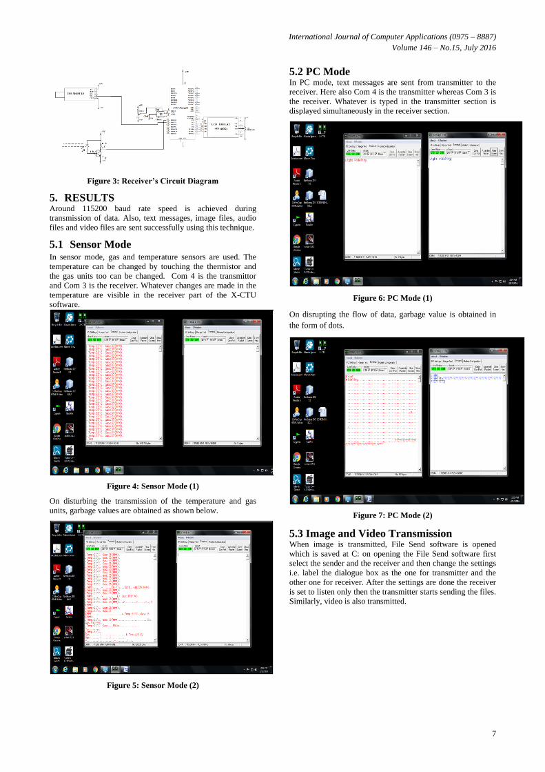
Figure 3: Receiver’s Circuit Diagram
5. RESULTS Around 115200 baud rate speed is achieved during
transmission of data. Also, text messages, image files, audio
files and video files are sent successfully using this technique.
5.1 Sensor Mode In sensor mode, gas and temperature sensors are used. The
temperature can be changed by touching the thermistor and
the gas units too can be changed. Com 4 is the transmittor
and Com 3 is the receiver. Whatever changes are made in the
temperature are visible in the receiver part of the X-CTU
software.
Figure 4: Sensor Mode (1)
On disturbing the transmission of the temperature and gas
units, garbage values are obtained as shown below.
Figure 5: Sensor Mode (2)
5.2 PC Mode In PC mode, text messages are sent from transmitter to the
receiver. Here also Com 4 is the transmitter whereas Com 3 is
the receiver. Whatever is typed in the transmitter section is
displayed simultaneously in the receiver section.
Figure 6: PC Mode (1)
On disrupting the flow of data, garbage value is obtained in
the form of dots.
Figure 7: PC Mode (2)
5.3 Image and Video Transmission When image is transmitted, File Send software is opened
which is saved at C: on opening the File Send software first
select the sender and the receiver and then change the settings
i.e. label the dialogue box as the one for transmitter and the
other one for receiver. After the settings are done the receiver
is set to listen only then the transmitter starts sending the files.
Similarly, video is also transmitted.
International Journal of Computer Applications (0975 – 8887)
Volume 146 – No.15, July 2016
8
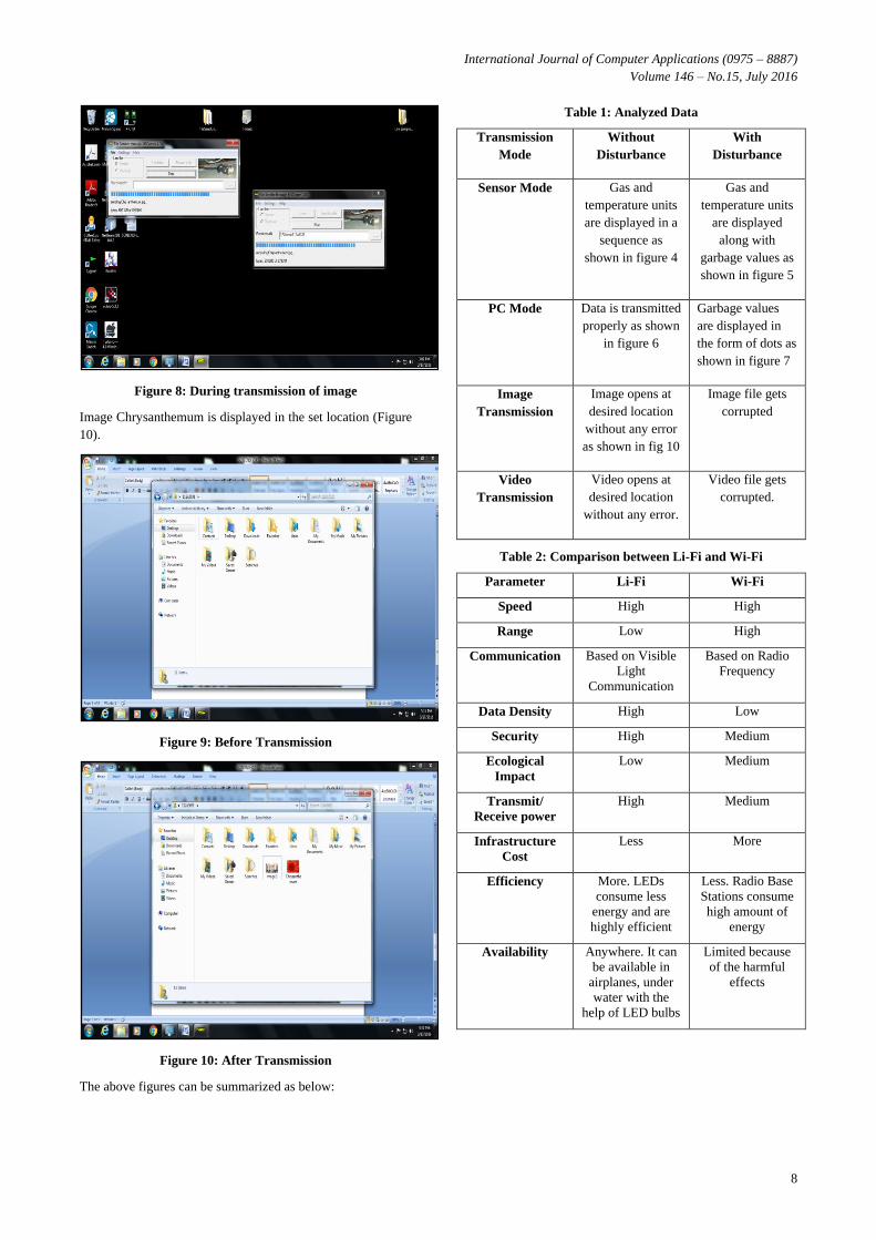
Figure 8: During transmission of image
Image Chrysanthemum is displayed in the set location (Figure
10).
Figure 9: Before Transmission
Figure 10: After Transmission
The above figures can be summarized as below:
Table 1: Analyzed Data
Transmission
Mode
Without
Disturbance
With
Disturbance
Sensor Mode Gas and
temperature units
are displayed in a
sequence as
shown in figure 4
Gas and
temperature units
are displayed
along with
garbage values as
shown in figure 5
PC Mode Data is transmitted
properly as shown
in figure 6
Garbage values
are displayed in
the form of dots as
shown in figure 7
Image
Transmission
Image opens at
desired location
without any error
as shown in fig 10
Image file gets
corrupted
Video
Transmission
Video opens at
desired location
without any error.
Video file gets
corrupted.
Table 2: Comparison between Li-Fi and Wi-Fi
Parameter Li-Fi Wi-Fi
Speed High High
Range Low High
Communication Based on Visible
Light
Communication
Based on Radio
Frequency
Data Density High Low
Security High Medium
Ecological
Impact
Low Medium
Transmit/
Receive power
High Medium
Infrastructure
Cost
Less More
Efficiency More. LEDs
consume less
energy and are
highly efficient
Less. Radio Base
Stations consume
high amount of
energy
Availability Anywhere. It can
be available in
airplanes, under
water with the
help of LED bulbs
Limited because
of the harmful
effects
International Journal of Computer Applications (0975 – 8887)
Volume 146 – No.15, July 2016
9
6. CONCLUSION
6.1 Advantages Li-Fi works like a wide-area Wi-Fi hotspot as the light
waves do not penetrate through walls and hence it is very
secure.
It provides very low electromagnetic interference which
allows connectivity in areas where Wi-Fi is not allowed.
Also, the equipment used in the project are very cheap so
the overall cost is low.
6.2 Applications
Since Li-Fi uses just light, it can be used safely in
aircrafts and hospitals which are prone to interference
from radio waves.
Radio waves are quickly absorbed in water but light can
penetrate large distances and headlamps are used for
communicating under water.
Li-Fi can be used in petroleum or chemical plants where
other transmission or frequencies could be hazardous.
7. ACKNOWLEDGMENTS Thanks to the guide Prof. K. Lakshmisudha who have
contributed towards development of the project.
8. REFERENCES [1] WANG Jia-yuan,ZOU Nian-yu,WANG Dong,
“Experimental Study on visible light communication
based on LED”,
www.sciencedirect.com/science/article/pii/S1005888511
604226
[2] Jyoti Rani, Prerna Chauhan, Ritika Tripathi, “Li-Fi
(Light Fidelity)-The future technology In Wireless
communication” , International Journal of Applied
Engineering Research, ISSN 0973-4562 ,Vol.7, No.11
,2012.
[3] N. Navyatha, T.M. Prathyusha, V. Roja, M.
Mounika,“Li-Fi(Light Fidelity): LED based
alternative”,www.ijser.org/researchpaper%5CLi-Fi-
Light-fidelity-LED-Based-Alternative.pdf
[4] Rahul.R.Sharma, Raunak, Akshay Sanganal, “Li-Fi
Technology”,
www.ijcta.com/documents/volumes/vol5issueI/ijcta2014
050121.pdf
[5] Dhakane Vikas Nivrutti, Ravi Ramchandra Nimbalkar
,Li-Fi: A Reconnaissance of future technology,
http://www.ijarcsse.com/docs/papers/Volume_3/11_Nov
ember2013/V3I11-0434.pdf
[6] Vitthal.S, Saptasagare: Next of Wi-Fi an future
technology in wireless networking Li-fi using LED over
internet of Things
[7] Gagandeep Kaur Virk,“Li-Fi : A new communication
mechanism”,
research.ijcaonline.org/volume118/number15/pxc390342
1.pdf
[8] Jay H. Bhut, Dharmrajsinh N. Parmar, Khushbu V.
Mehta, “LI-FI Technology – A Visible Light
Communication”,
https://www.ijedr.org/papers/IJEDRCP1401007.pdf
[9] Sinku U. Gupta, “Research on Li-Fi Technology&
Comparison of Li-Fi/Wi-Fi”,
http://www.lemarson.com/public/upload/ressource/filena
me/Li-Fi_Gupta.pdf
[10] Giriraj KR. Patidar, “LI‐FI TECHNOLOGY IN
WIRELESS COMMUNICATION”,
http://www.ijset.in/wp-
content/uploads/2014/12/122014.1389_LiFi_126-130.pdf
[11] M. A. Hadi, “Wireless Communication tends to Smart
Technology Li-Fi and its comparison with Wi-Fi”,
http://www.ajer.org/papers/v5(05)/F0505040047.pdf
[12] Smita Pawar, Tyran Kinny, Franklin Puthuva, Ashore
Komban, Dipti Belekar, “DATA COMMUNICATION
USING VISIBLE LIGHT”,
http://www.giapjournals.org/uploads/2/6/6/2/26621256/d
ata_communication_using_visible_light.pdf
[13] Bhavya R., Lokesh M. R, “A Survey on Li-Fi
Technology”, http://www.aijet.in/v3/1601003.pdf
[14] Deepali Bajaj, Isha Mangal, Asha Yadav, “Towards an
understanding of Li-Fi: Next generation Visible Light
Communication Technology”,
http://www.ijecs.in/issue/v4-i4/101%20ijecs.pdf
IJCATM : www.ijcaonline.org
![A Novel Approach for Reliable High Speed Data Transmission ... · LIGHT-FIDELITY (Li-Fi)[1-2]. Li-Fi is the new upcoming technology which was introduced by Professor Harald Haas](https://img.pdfslide.us/doc/110x75/5e89d1f8c570ba13065bb832/a-novel-approach-for-reliable-high-speed-data-transmission-light-fidelity-li-fi1-2.jpg)

![Highway Navigation System using Light Fidelity Technology€¦ · Li-Fi (light fidelity technology) is the recent technology that emerged in the Field of wireless communication [3]](https://img.pdfslide.us/doc/110x75/605b5a9956d1461390052072/highway-navigation-system-using-light-fidelity-technology-li-fi-light-fidelity.jpg)