Embed Size (px)
Citation preview
E / 11800 / A
LHD ULTRA series – digital low diff erential pressure sensors
Page 1/16Subject to change without notice www.first-sensor.com [email protected]
Features
– Pressure ranges from 1250 to 5000 Pa
(5 to 20 inH2O) with resolution of ~0.05 Pa
(0.0002 inH2O) at low pressure
– Pressure sensor based on thermal micro-
flow measurement
– High flow impedance
– very low flow-through leakage
– high immunity to dust and humidity
– no loss in sensitivity using long tubing
– Outstanding long-term stability and precision
with patented real-time off set compensation
and linearization techniques
– Outstanding total accuracy better than
typ. 1.5% of measured value (typical) from
1% to 100% of full scale
– On-board temperature sensor and
barometer
– Pin-configurable digital I²C or SPI output
– Operating temperature range -40...+85 °C
– Low profile surface mount package with
auxiliary flat cable connector
– Pressure ports for direct manifold assemblies
– Highly versatile to fit to application-specific
mounting adaptors and manifolds
– Minimized internal volume and manifold mount
option allow for fast gas purge time
Certificates
– Quality Management System according to
EN ISO 13485 and EN ISO 9001
– RoHS and REACH compliant
– Moisture sensitivity level 3 test
Media compatibility
Air and other non-corrosive gases
Applications
Medical
– Ventilators
– Spirometers
– CPAP
– Sleep diagnostic equipment
– Nebulizers
– Oxygen conservers/concentrators
– Insuff lators/endoscopy
Industrial
– HVAC
– VAV
– Filter monitoring
– Burner control
– Fuel cells
– Gas leak detection
– Fume hood
– Instrumentation
– Security systems
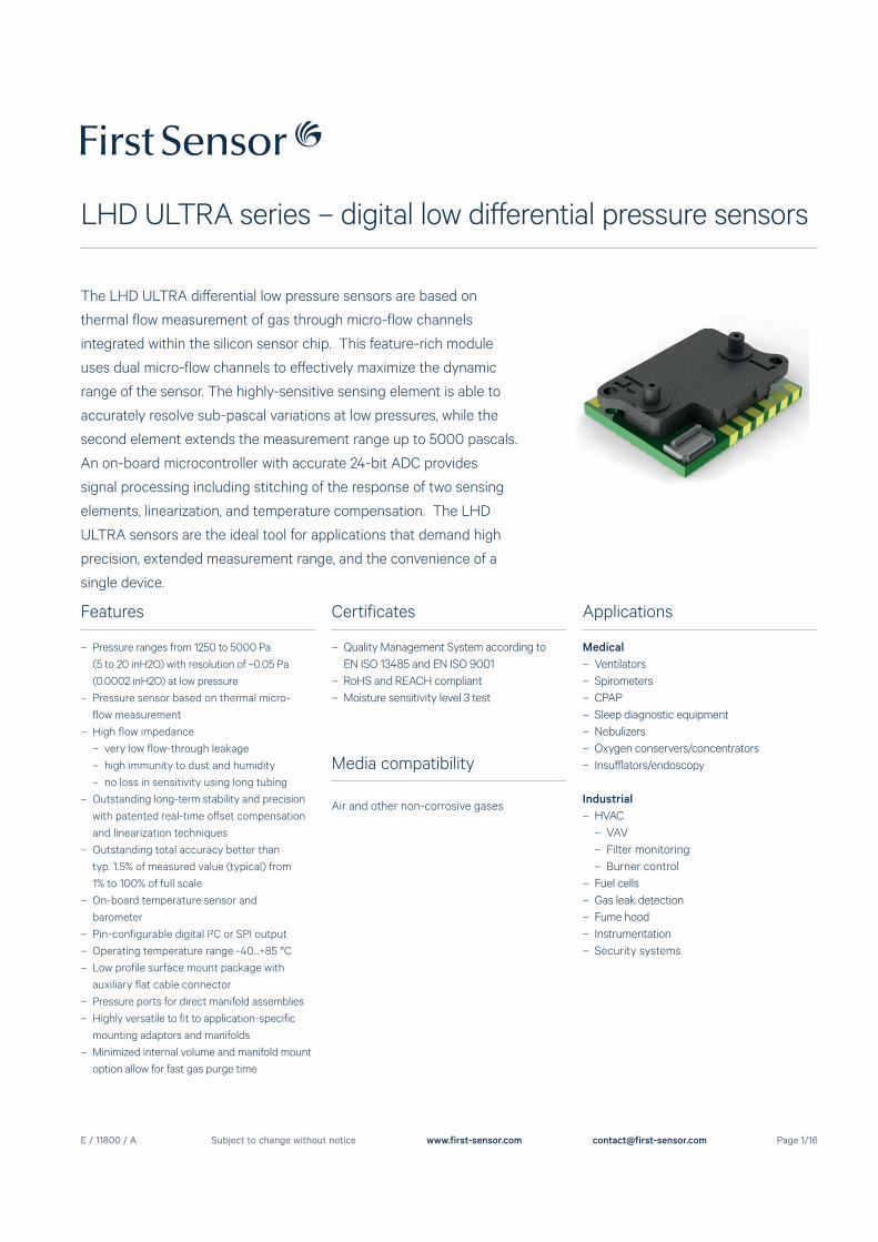
The LHD ULTRA diff erential low pressure sensors are based on
thermal flow measurement of gas through micro-flow channels
integrated within the silicon sensor chip. This feature-rich module
uses dual micro-flow channels to eff ectively maximize the dynamic
range of the sensor. The highly-sensitive sensing element is able to
accurately resolve sub-pascal variations at low pressures, while the
second element extends the measurement range up to 5000 pascals.
An on-board microcontroller with accurate 24-bit ADC provides
signal processing including stitching of the response of two sensing
elements, linearization, and temperature compensation. The LHD
ULTRA sensors are the ideal tool for applications that demand high
precision, extended measurement range, and the convenience of a
single device.
E / 11800 / A
LHD ULTRA series – digital low diff erential pressure sensors
Page 2/16Subject to change without notice www.first-sensor.com [email protected]
Specification notes
(1) Recommendations only. Actually reflow settings depend on many factors, for example, number of oven heating and cooling zones, type of solder paste/flux used, board and component size, as well as component density. It is the responsibility of the customer to fine tune their processes for optimal results.(2) Handling instruction: Products are packaged in vacuum sealed moisture bar rier bag with a floor life of 168hours (<30C, 60% R.H.). If floor life or environmental conditions have been exceeded prior to reflow assembly, baking is recommended. Recommended bake-out procedure is 72 hours @ 60C.(3) For temperature ranges above 85 °C please contact First Sensor.
(4) Sweep 20 to 2000 Hz, 8 min, 4 cycles per axis, MIL-STD-883, Method 2007.(5) 5 shocks, 3 axes, MIL-STD-883E, Method 2002.4.(6) The max. common mode pressure is 5 bar.(7) For example with a LHD ULTRAM025... sensor measuring CO
2 gas, at full-scale
output the actual pressure will be:
ΔPeff
= ΔPSensor
x gas correction factor = 2500 Pa x 0.56 = 1400 Pa
ΔPeff
= True diff erential pressure ΔP
Sensor= Diff erential pressure as indicated by output signal
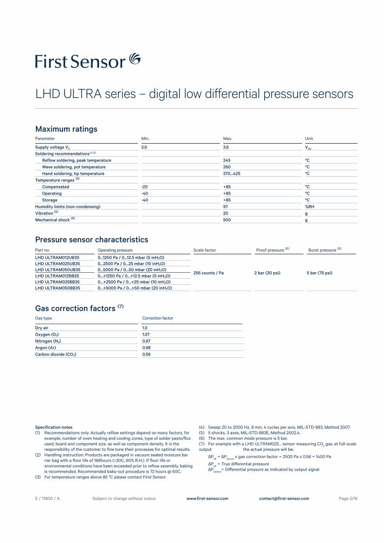
Pressure sensor characteristics
Parameter Min. Max. Unit
Supply voltage VS 3.0 3.6 VDC
Soldering recommendations (1, 2)
Reflow soldering, peak temperature 245 °C
Wave soldering, pot temperature 260 °C
Hand soldering, tip temperature 370...425 °C
Temperature ranges (3)
Compensated -20 +85 °C
Operating -40 +85 °C
Storage -40 +85 °C
Humidity limits (non-condensing) 97 %RH
Vibration (4) 20 g
Mechanical shock (5) 500 g
Maximum ratings
Gas type Correction factor
Dry air 1.0
Oxygen (O2) 1.07
Nitrogen (N2) 0.97
Argon (Ar) 0.98
Carbon dioxide (CO2) 0.56
Gas correction factors (7)
Part no. Operating pressure Scale factor Proof pressure (6) Burst pressure (6)
LHD ULTRAM012UB3S 0...1250 Pa / 0...12.5 mbar (5 inH2O)
256 counts / Pa 2 bar (30 psi) 5 bar (75 psi)
LHD ULTRAM025UB3S 0...2500 Pa / 0...25 mbar (10 inH2O)
LHD ULTRAM050UB3S 0...5000 Pa / 0...50 mbar (20 inH2O)
LHD ULTRAM012BB3S 0...±1250 Pa / 0...±12.5 mbar (5 inH2O)
LHD ULTRAM025BB3S 0...±2500 Pa / 0...±25 mbar (10 inH2O)
LHD ULTRAM050BB3S 0...±5000 Pa / 0...±50 mbar (20 inH2O)
E / 11800 / A
LHD ULTRA series – digital low diff erential pressure sensors
Page 3/16Subject to change without notice www.first-sensor.com [email protected]
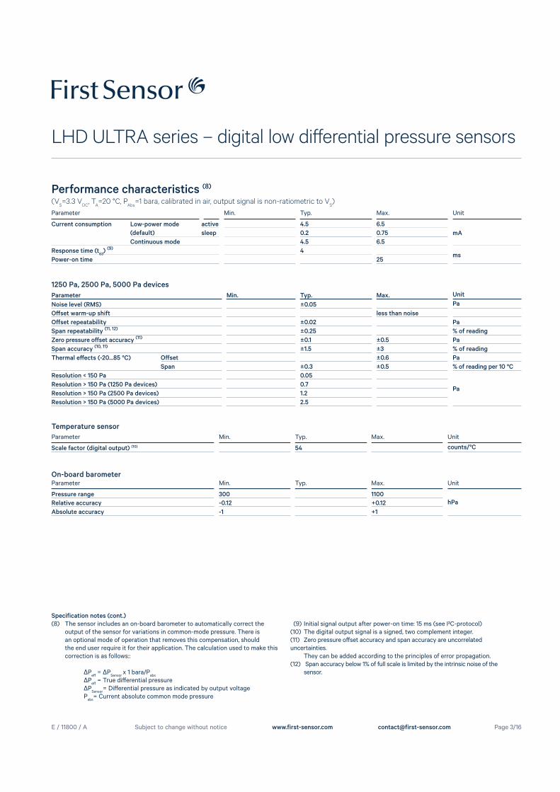
Performance characteristics (8)
(VS=3.3 V
DC, T
A=20 °C, P
Abs=1 bara, calibrated in air, output signal is non-ratiometric to V
S)
Parameter Min. Typ. Max. Unit
Current consumption Low-power mode active 4.5 6.5
mA(default) sleep 0.2 0.75
Continuous mode 4.5 6.5
Response time (t63
) (9) 4ms
Power-on time 25
Parameter Min. Typ. Max. Unit
Noise level (RMS) ±0.05 Pa
Off set warm-up shift less than noise
Off set repeatability ±0.02 Pa
Span repeatability (11, 12) ±0.25 % of reading
Zero pressure off set accuracy (11) ±0.1 ±0.5 Pa
Span accuracy (10, 11) ±1.5 ±3 % of reading
Thermal eff ects (-20...85 °C) Off set ±0.6 Pa
Span ±0.3 ±0.5 % of reading per 10 °C
Resolution < 150 Pa 0.05
PaResolution > 150 Pa (1250 Pa devices) 0.7
Resolution > 150 Pa (2500 Pa devices) 1.2
Resolution > 150 Pa (5000 Pa devices) 2.5
Specification notes (cont.)
(8) The sensor includes an on-board barometer to automatically correct the output of the sensor for variations in common-mode pressure. There is an optional mode of operation that removes this compensation, should the end user require it for their application. The calculation used to make this correction is as follows::
ΔPeff
= ΔPSensor
x 1 bara/Pabs
ΔPeff
= True diff erential pressure ΔP
Sensor= Diff erential pressure as indicated by output voltage
Pabs
= Current absolute common mode pressure
(9) Initial signal output after power-on time: 15 ms (see I²C-protocol)(10) The digital output signal is a signed, two complement integer. (11) Zero pressure off set accuracy and span accuracy are uncorrelated uncertainties. They can be added according to the principles of error propagation.(12) Span accuracy below 1% of full scale is limited by the intrinsic noise of the sensor.
Temperature sensor
Parameter Min. Typ. Max. Unit
Scale factor (digital output) (10) 54 counts/°C
On-board barometerParameter Min. Typ. Max. Unit
Pressure range 300 1100
hPaRelative accuracy -0.12 +0.12
Absolute accuracy -1 +1
1250 Pa, 2500 Pa, 5000 Pa devices
E / 11800 / A
LHD ULTRA series – digital low diff erential pressure sensors
Page 4/16Subject to change without notice www.first-sensor.com [email protected]
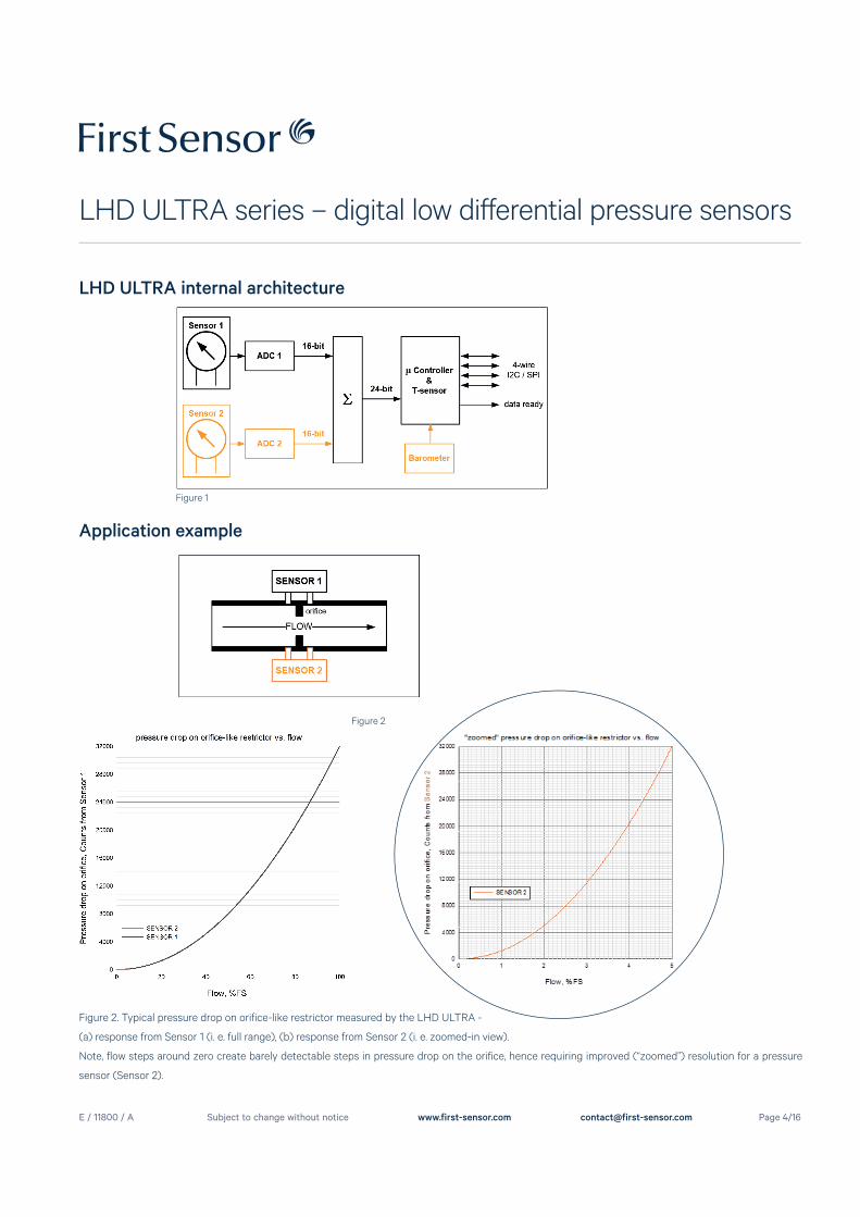
LHD ULTRA internal architecture
Figure 1
Application example
Figure 2. Typical pressure drop on orifice-like restrictor measured by the LHD ULTRA -
(a) response from Sensor 1 (i. e. full range), (b) response from Sensor 2 (i. e. zoomed-in view).
Note, flow steps around zero create barely detectable steps in pressure drop on the orifice, hence requiring improved (“zoomed”) resolution for a pressure
sensor (Sensor 2).
Figure 2
E / 11800 / A
LHD ULTRA series – digital low diff erential pressure sensors
Page 5/16Subject to change without notice www.first-sensor.com [email protected]
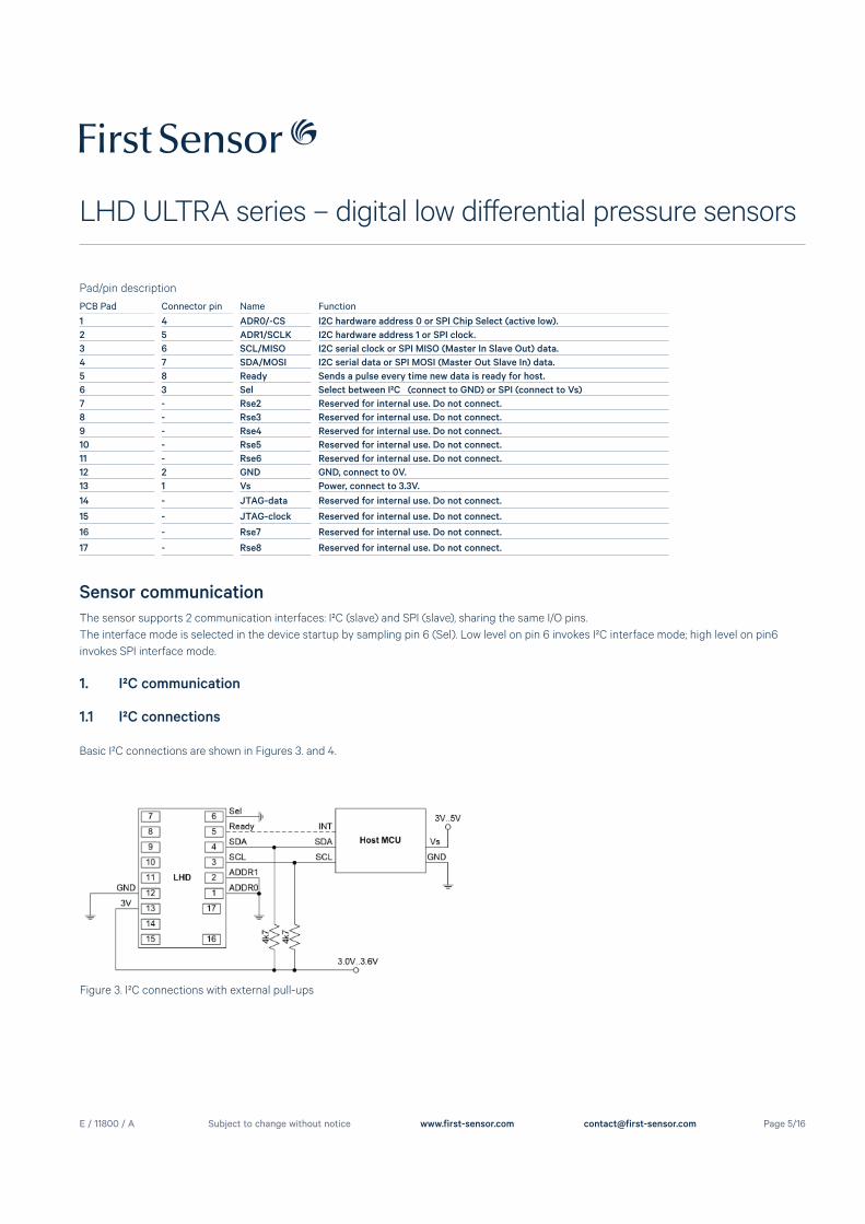
PCB Pad Connector pin Name Function1 4 ADR0/-CS I2C hardware address 0 or SPI Chip Select (active low).
2 5 ADR1/SCLK I2C hardware address 1 or SPI clock.
3 6 SCL/MISO I2C serial clock or SPI MISO (Master In Slave Out) data.
4 7 SDA/MOSI I2C serial data or SPI MOSI (Master Out Slave In) data.
5 8 Ready Sends a pulse every time new data is ready for host.
6 3 Sel Select between I²C (connect to GND) or SPI (connect to Vs)
7 - Rse2 Reserved for internal use. Do not connect.
8 - Rse3 Reserved for internal use. Do not connect.
9 - Rse4 Reserved for internal use. Do not connect.
10 - Rse5 Reserved for internal use. Do not connect.
11 - Rse6 Reserved for internal use. Do not connect.
12 2 GND GND, connect to 0V.
13 1 Vs Power, connect to 3.3V.
14 - JTAG-data Reserved for internal use. Do not connect.
15 - JTAG-clock Reserved for internal use. Do not connect.
16 - Rse7 Reserved for internal use. Do not connect.
17 - Rse8 Reserved for internal use. Do not connect.
Pad/pin description
Sensor communication
The sensor supports 2 communication interfaces: I²C (slave) and SPI (slave), sharing the same I/O pins.
The interface mode is selected in the device startup by sampling pin 6 (Sel). Low level on pin 6 invokes I²C interface mode; high level on pin6
invokes SPI interface mode.
1. I²C communication
1.1 I²C connections
Basic I²C connections are shown in Figures 3. and 4.
Figure 3. I²C connections with external pull-ups
E / 11800 / A
LHD ULTRA series – digital low diff erential pressure sensors
Page 6/16Subject to change without notice www.first-sensor.com [email protected]
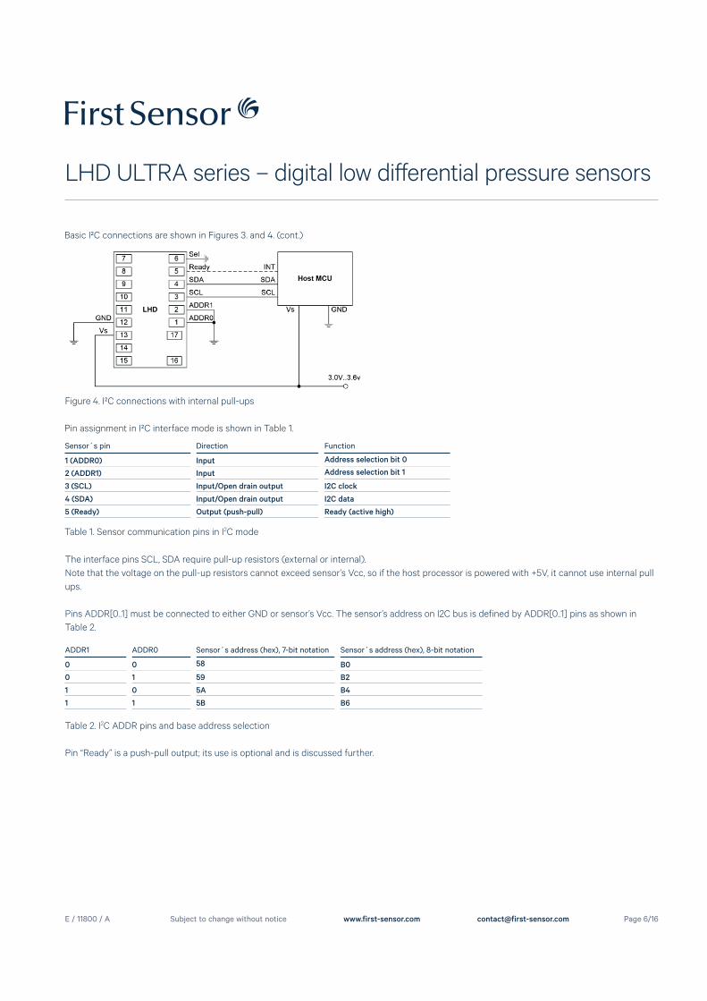
Sensor´s pin Direction Function
1 (ADDR0) Input Address selection bit 0
2 (ADDR1) Input Address selection bit 1
3 (SCL) Input/Open drain output I2C clock
4 (SDA) Input/Open drain output I2C data
5 (Ready) Output (push-pull) Ready (active high)
Figure 4. I²C connections with internal pull-ups
Pin assignment in I²C interface mode is shown in Table 1.
Table 1. Sensor communication pins in I2C mode
The interface pins SCL, SDA require pull-up resistors (external or internal).
Note that the voltage on the pull-up resistors cannot exceed sensor’s Vcc, so if the host processor is powered with +5V, it cannot use internal pull
ups.
Pins ADDR[0..1] must be connected to either GND or sensor’s Vcc. The sensor’s address on I2C bus is defined by ADDR[0..1] pins as shown in
Table 2.
ADDR1 ADDR0 Sensor´s address (hex), 7-bit notation Sensor´s address (hex), 8-bit notation
0 0 58 B0
0 1 59 B2
1 0 5A B4
1 1 5B B6
Table 2. I2C ADDR pins and base address selection
Pin “Ready” is a push-pull output; its use is optional and is discussed further.
Basic I²C connections are shown in Figures 3. and 4. (cont.)
E / 11800 / A
LHD ULTRA series – digital low diff erential pressure sensors
Page 7/16Subject to change without notice www.first-sensor.com [email protected]
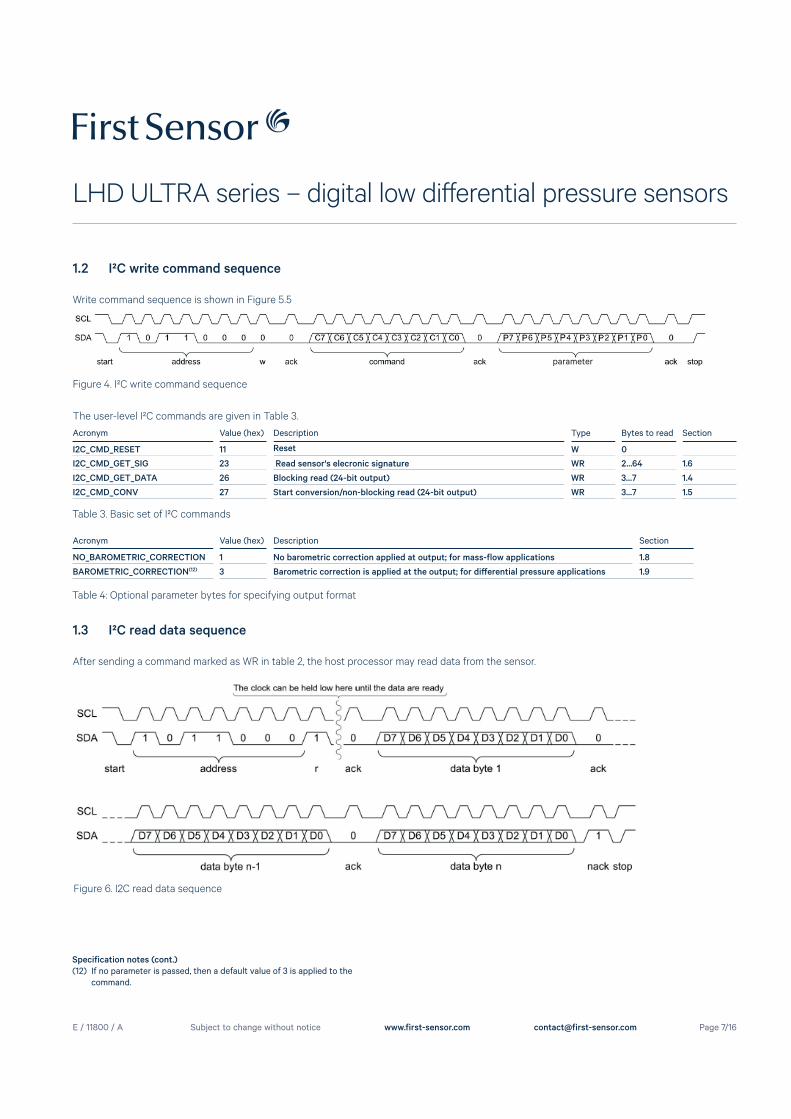
1.2 I²C write command sequence
Write command sequence is shown in Figure 5.5
Figure 4. I²C write command sequence
Acronym Value (hex) Description Type Bytes to read Section
I2C_CMD_RESET 11 Reset W 0
I2C_CMD_GET_SIG 23 Read sensor's elecronic signature WR 2...64 1.6
I2C_CMD_GET_DATA 26 Blocking read (24-bit output) WR 3...7 1.4
I2C_CMD_CONV 27 Start conversion/non-blocking read (24-bit output) WR 3...7 1.5
The user-level I²C commands are given in Table 3.
Table 3. Basic set of I²C commands
Acronym Value (hex) Description Section
NO_BAROMETRIC_CORRECTION 1 No barometric correction applied at output; for mass-flow applications 1.8
BAROMETRIC_CORRECTION(12) 3 Barometric correction is applied at the output; for diff erential pressure applications 1.9
Specification notes (cont.)
(12) If no parameter is passed, then a default value of 3 is applied to the command.
parameter
Table 4: Optional parameter bytes for specifying output format
Figure 6. I2C read data sequence
1.3 I²C read data sequence
After sending a command marked as WR in table 2, the host processor may read data from the sensor.
E / 11800 / A
LHD ULTRA series – digital low diff erential pressure sensors
Page 8/16Subject to change without notice www.first-sensor.com [email protected]
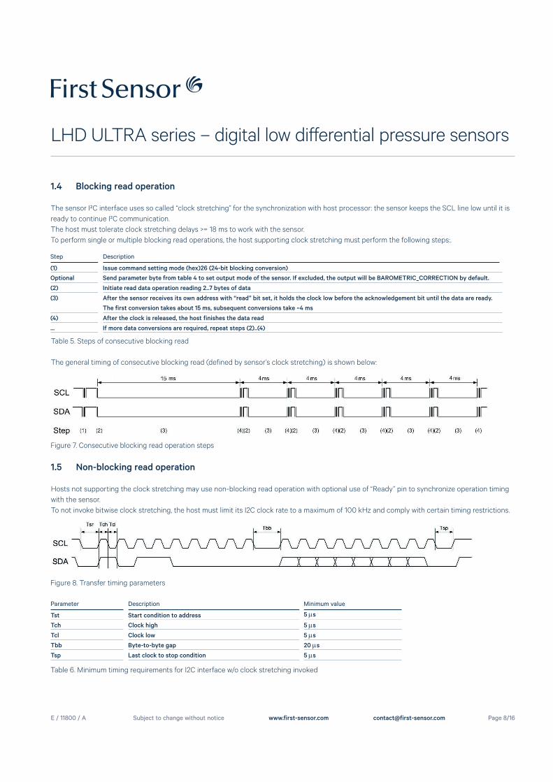
Figure 7. Consecutive blocking read operation steps
1.4 Blocking read operation
The sensor I²C interface uses so called “clock stretching” for the synchronization with host processor: the sensor keeps the SCL line low until it is
ready to continue I²C communication.
The host must tolerate clock stretching delays >= 18 ms to work with the sensor.
To perform single or multiple blocking read operations, the host supporting clock stretching must perform the following steps:.
Step Description
(1) Issue command setting mode (hex)26 (24-bit blocking conversion)
Optional Send parameter byte from table 4 to set output mode of the sensor. If excluded, the output will be BAROMETRIC_CORRECTION by default.
(2) Initiate read data operation reading 2..7 bytes of data
(3) After the sensor receives its own address with “read” bit set, it holds the clock low before the acknowledgement bit until the data are ready.
The first conversion takes about 15 ms, subsequent conversions take ~4 ms
(4) After the clock is released, the host finishes the data read
... If more data conversions are required, repeat steps (2)..(4)
Table 5. Steps of consecutive blocking read
The general timing of consecutive blocking read (defined by sensor’s clock stretching) is shown below:
1.5 Non-blocking read operation
Hosts not supporting the clock stretching may use non-blocking read operation with optional use of “Ready” pin to synchronize operation timing
with the sensor.
To not invoke bitwise clock stretching, the host must limit its I2C clock rate to a maximum of 100 kHz and comply with certain timing restrictions.
Figure 8. Transfer timing parameters
Parameter Description Minimum value
Tst Start condition to address 5 s
Tch Clock high 5 s
Tcl Clock low 5 s
Tbb Byte-to-byte gap 20 s
Tsp Last clock to stop condition 5 s
Table 6. Minimum timing requirements for I2C interface w/o clock stretching invoked
E / 11800 / A
LHD ULTRA series – digital low diff erential pressure sensors
Page 9/16Subject to change without notice www.first-sensor.com [email protected]
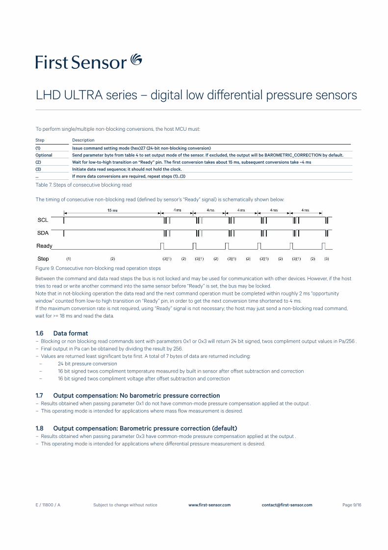
Step Description
(1) Issue command setting mode (hex)27 (24-bit non-blocking conversion)
Optional Send parameter byte from table 4 to set output mode of the sensor. If excluded, the output will be BAROMETRIC_CORRECTION by default.
(2) Wait for low-to-high transition on “Ready” pin. The first conversion takes about 15 ms, subsequent conversions take ~4 ms
(3) Initiate data read sequence; it should not hold the clock.
... If more data conversions are required, repeat steps (1)..(3)
To perform single/multiple non-blocking conversions, the host MCU must:
Table 7. Steps of consecutive blocking read
The timing of consecutive non-blocking read (defined by sensor’s “Ready” signal) is schematically shown below:
Figure 9. Consecutive non-blocking read operation steps
Between the command and data read steps the bus is not locked and may be used for communication with other devices. However, if the host
tries to read or write another command into the same sensor before “Ready” is set, the bus may be locked.
Note that in not-blocking operation the data read and the next command operation must be completed within roughly 2 ms “opportunity
window” counted from low-to high transition on “Ready” pin, in order to get the next conversion time shortened to 4 ms.
If the maximum conversion rate is not required, using “Ready” signal is not necessary; the host may just send a non-blocking read command,
wait for >= 18 ms and read the data.
1.6 Data format – Blocking or non blocking read commands sent with parameters 0x1 or 0x3 will return 24 bit signed, twos compliment output values in Pa/256 .
– Final output in Pa can be obtained by dividing the result by 256.
– Values are returned least significant byte first. A total of 7 bytes of data are returned including:
– 24 bit pressure conversion
– 16 bit signed twos compliment temperature measured by built in sensor after off set subtraction and correction
– 16 bit signed twos compliment voltage after off set subtraction and correction
1.7 Output compensation: No barometric pressure correction – Results obtained when passing parameter 0x1 do not have common-mode pressure compensation applied at the output .
– This operating mode is intended for applications where mass flow measurement is desired.
1.8 Output compensation: Barometric pressure correction (default) – Results obtained when passing parameter 0x3 have common-mode pressure compensation applied at the output .
– This operating mode is intended for applications where diff erential pressure measurement is desired.
E / 11800 / A
LHD ULTRA series – digital low diff erential pressure sensors
Page 10/16Subject to change without notice www.first-sensor.com [email protected]
1.9 Reading electronic signature (I2C_CMD_GET_SIG)An electronic version of the device's serial number is stored in flash memory and is retrievable with the command 0x23. The contents of the elec-
tronic signature are as follows.
Sequence Parameter Size Data type Comment0-1 Firmware version 2 bytes byte[2] array byte[1] -> major version number, byte[0] -> minor version number
2-12 Part number (11 characters) 11 bytes char[12] array
13-19 Lot number (7 characters) 7 bytes char[7] array e.g. CV7T001
20-21 Pressure range 2 bytes unsigned int 0 to 65535, MSB-first
22 Output type 1 byte char e.g. U or B
23-24 Scale factor 2 bytes unsigned int 0 to 65535, MSB-first
25-26 Calibration ID 2 bytes 2 x 2 char e.g. AA
27 Week number 1 byte short int 0 to 255
28 Year number 1 byte short int 0 to 255
29-30 Sequence number 2 bytes unsigned int o to 65535, MSB-first
31-63 Reserved 33 bytes OxFF Reserved for future use
Table 8. Electronic signature
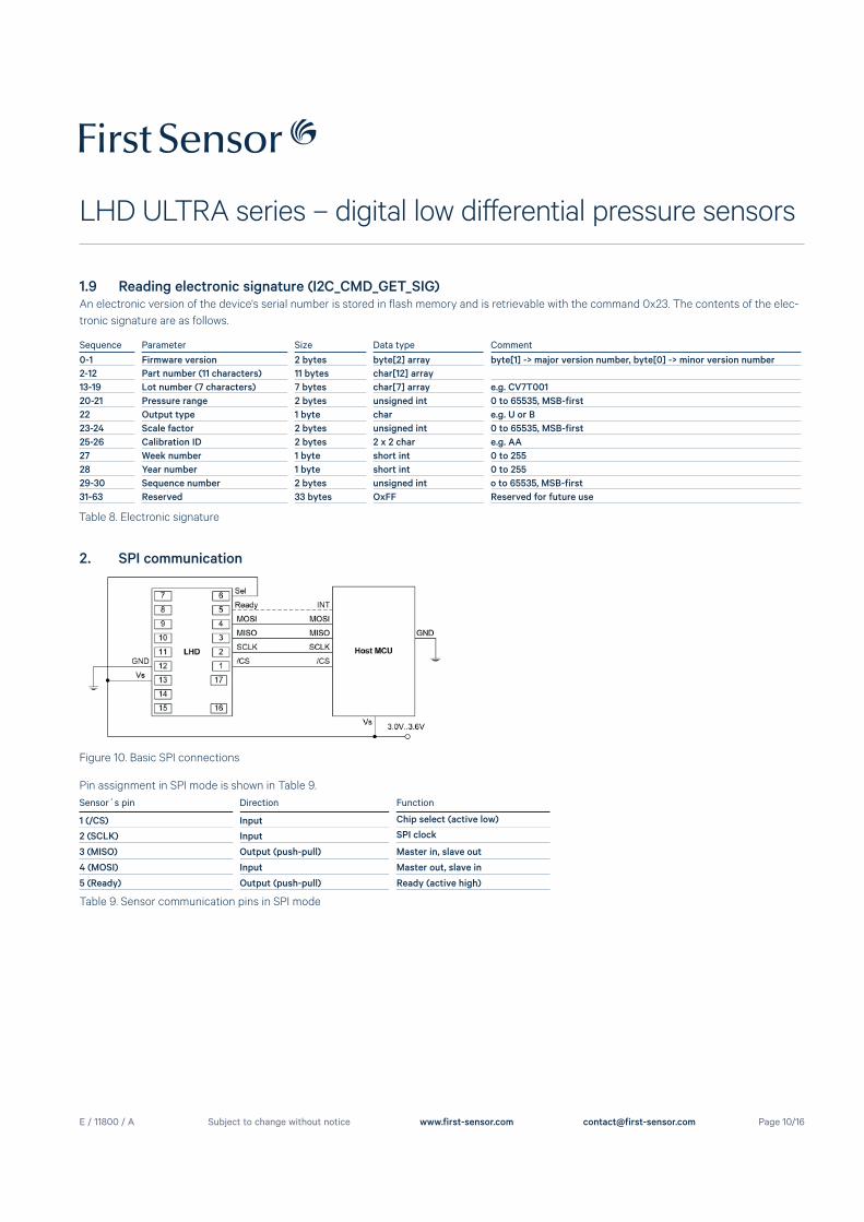
2. SPI communication
Sensor´s pin Direction Function
1 (/CS) Input Chip select (active low)
2 (SCLK) Input SPI clock
3 (MISO) Output (push-pull) Master in, slave out
4 (MOSI) Input Master out, slave in
5 (Ready) Output (push-pull) Ready (active high)
Pin assignment in SPI mode is shown in Table 9.
Table 9. Sensor communication pins in SPI mode
Figure 10. Basic SPI connections
E / 11800 / A
LHD ULTRA series – digital low diff erential pressure sensors
Page 11/16Subject to change without notice www.first-sensor.com [email protected]
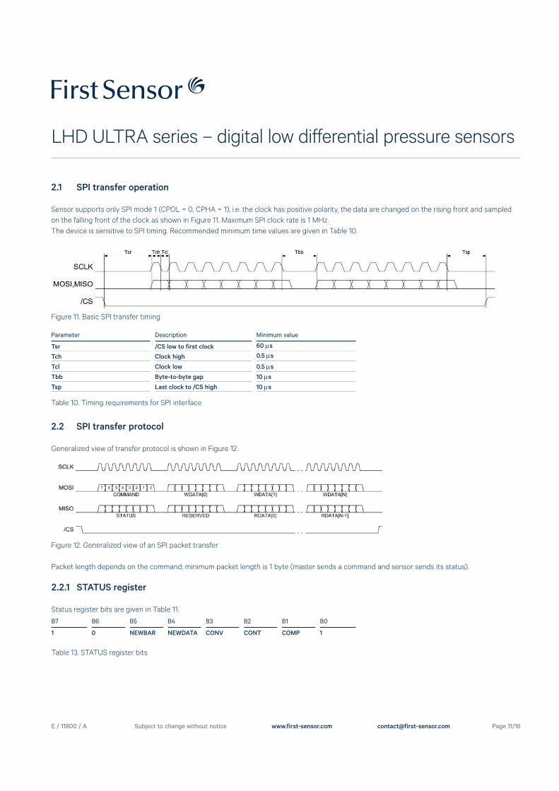
2.1 SPI transfer operation
Sensor supports only SPI mode 1 (CPOL = 0, CPHA = 1), i.e. the clock has positive polarity, the data are changed on the rising front and sampled
on the falling front of the clock as shown in Figure 11. Maximum SPI clock rate is 1 MHz.
The device is sensitive to SPI timing. Recommended minimum time values are given in Table 10.
Figure 11. Basic SPI transfer timing
Table 10. Timing requirements for SPI interface
Parameter Description Minimum value
Tsr /CS low to first clock 60 s
Tch Clock high 0.5 s
Tcl Clock low 0.5 s
Tbb Byte-to-byte gap 10 s
Tsp Last clock to /CS high 10 s
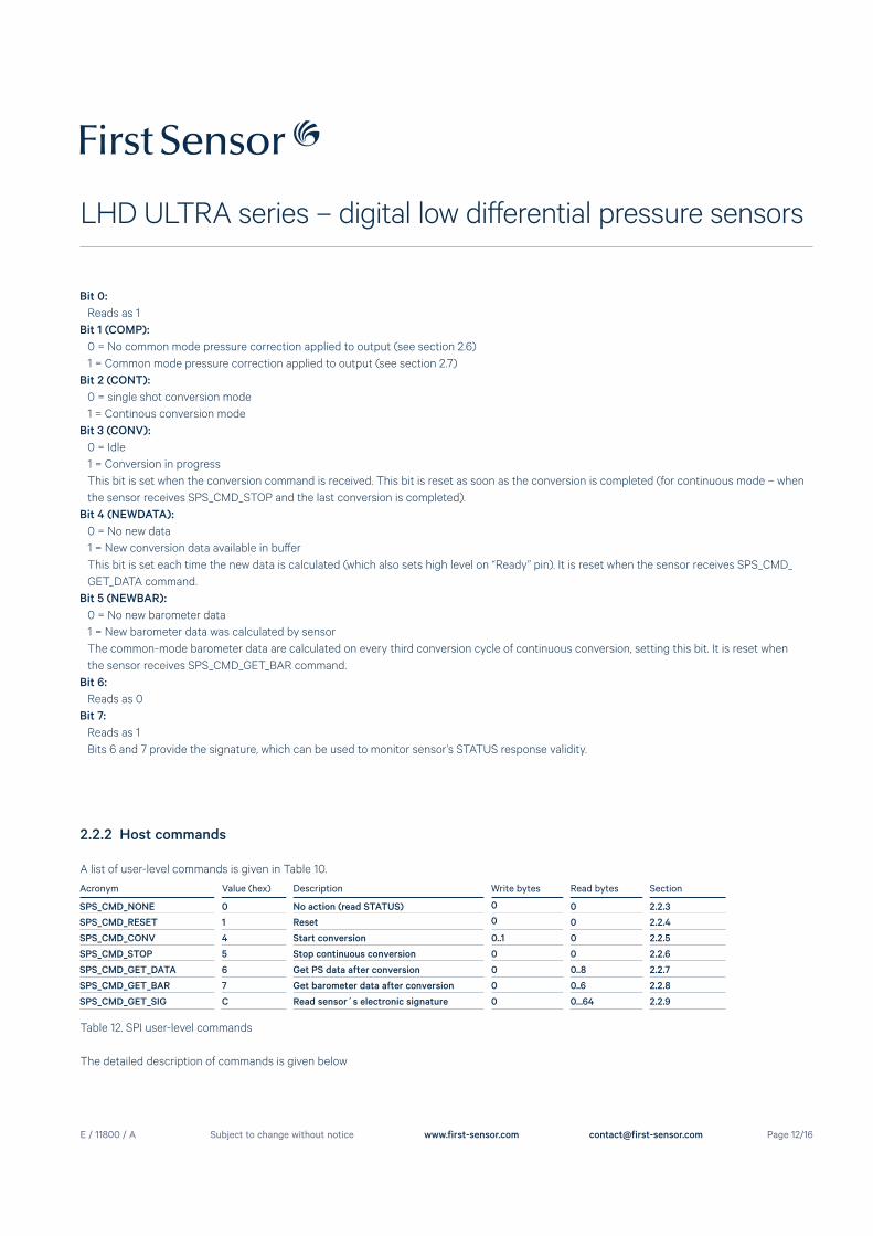
2.2 SPI transfer protocol
Generalized view of transfer protocol is shown in Figure 12.
Figure 12. Generalized view of an SPI packet transfer
Packet length depends on the command; minimum packet length is 1 byte (master sends a command and sensor sends its status).
B7 B6 B5 B4 B3 B2 B1 B0
1 0 NEWBAR NEWDATA CONV CONT COMP 1
Table 13. STATUS register bits
2.2.1 STATUS register
Status register bits are given in Table 11.
E / 11800 / A
LHD ULTRA series – digital low diff erential pressure sensors
Page 12/16Subject to change without notice www.first-sensor.com [email protected]
Bit 0:
Reads as 1
Bit 1 (COMP):
0 = No common mode pressure correction applied to output (see section 2.6)
1 = Common mode pressure correction applied to output (see section 2.7)
Bit 2 (CONT):
0 = single shot conversion mode
1 = Continous conversion mode
Bit 3 (CONV):
0 = Idle
1 = Conversion in progress
This bit is set when the conversion command is received. This bit is reset as soon as the conversion is completed (for continuous mode – when
the sensor receives SPS_CMD_STOP and the last conversion is completed).
Bit 4 (NEWDATA):
0 = No new data
1 = New conversion data available in buff er
This bit is set each time the new data is calculated (which also sets high level on “Ready” pin). It is reset when the sensor receives SPS_CMD_
GET_DATA command.
Bit 5 (NEWBAR):
0 = No new barometer data
1 = New barometer data was calculated by sensor
The common-mode barometer data are calculated on every third conversion cycle of continuous conversion, setting this bit. It is reset when
the sensor receives SPS_CMD_GET_BAR command.
Bit 6:
Reads as 0
Bit 7:
Reads as 1
Bits 6 and 7 provide the signature, which can be used to monitor sensor’s STATUS response validity.
2.2.2 Host commands
A list of user-level commands is given in Table 10.
Acronym Value (hex) Description Write bytes Read bytes Section
SPS_CMD_NONE 0 No action (read STATUS) 0 0 2.2.3
SPS_CMD_RESET 1 Reset 0 0 2.2.4
SPS_CMD_CONV 4 Start conversion 0..1 0 2.2.5
SPS_CMD_STOP 5 Stop continuous conversion 0 0 2.2.6
SPS_CMD_GET_DATA 6 Get PS data after conversion 0 0..8 2.2.7
SPS_CMD_GET_BAR 7 Get barometer data after conversion 0 0..6 2.2.8
SPS_CMD_GET_SIG C Read sensor´s electronic signature 0 0...64 2.2.9
Table 12. SPI user-level commands
The detailed description of commands is given below
E / 11800 / A
LHD ULTRA series – digital low diff erential pressure sensors
Page 13/16Subject to change without notice www.first-sensor.com [email protected]
2.2.5 SPS_CMD_CONV
Starts a new conversion. This command has a single byte parameter WDATA[0] with the following format:
B7 B6 B5 B4 B3 B2 B1 B0
- - - - - CONT COMP 1
Table 13. SPS_CMD_CONV command parameter
Bit 0:
Always passed as 1
Bit 1 (COMP):
0 = No common mode pressure correction applied to output (see section 2.6)
1 = Common mode pressure correction applied to output (see section 2.7)
Bit 2 (CONT):
0 = single shot conversion mode
1 = Continous conversion mode
2.2.6 SPS_CMD_STOP
Stops the continuous conversion mode. The current conversion will still be finished.
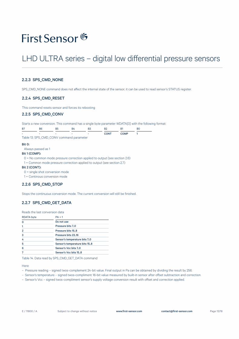
2.2.7 SPS_CMD_GET_DATA
Reads the last conversion data
Table 14. Data read by SPS_CMD_GET_DATA command
RDATA byte PA = 1
0 Do not use
1 Pressure bits 7..0
2 Pressure bits 15..8
3 Pressure bits 23..16
4 Sensor’s temperature bits 7..0
5 Sensor’s temperature bits 15..8
6 Sensor’s Vcc bits 7..0
7 Sensor’s Vcc bits 15..8
Here:
– Pressure reading – signed twos-complement 24-bit value. Final output in Pa can be obtained by dividing the result by 256.
– Sensor’s temperature – signed twos-compliment 16-bit value measured by built-in sensor after off set subtraction and correction.
– Sensor’s Vcc – signed twos-compliment sensor’s supply voltage conversion result with off set and correction applied.
2.2.3 SPS_CMD_NONE
SPS_CMD_NONE command does not aff ect the internal state of the sensor; it can be used to read sensor’s STATUS register.
2.2.4 SPS_CMD_RESET
This command resets sensor and forces its rebooting
E / 11800 / A
LHD ULTRA series – digital low diff erential pressure sensors
Page 14/16Subject to change without notice www.first-sensor.com [email protected]
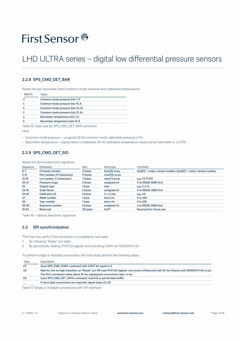
2.2.8 SPS_CMD_GET_BAR
Reads the last barometer data (common-mode pressure and calibrated temperature).
Table 15. Data read by SPS_CMD_GET_BAR command
RDATA Value
0 Common-mode pressure bits 7..0
1 Common-mode pressure bits 15..8
2 Common-mode pressure bits 23..16
3 Common-mode pressure bits 31..24
4 Barometer temperature bits 7..0
5 Barometer temperature bits 15..8
Here:
– Common-mode pressure – unsigned 32-bit common-mode calibrated pressure in Pa,
– Barometer temperature – signed twos-complement 16-bit calibrated temperature measured by barometer in oC/100
2.2.9 SPS_CMD_GET_SIG
Reads the device electronic signature.
Sequence Parameter Size Data type Comment0-1 Firmware version 2 bytes byte[2] array byte[1] -> major version number, byte[0] -> minor version number
2-12 Part number (11 characters) 11 bytes char[12] array
13-19 Lot number (7 characters) 7 bytes char[7] array e.g. CV7T001
20-21 Pressure range 2 bytes unsigned int 0 to 65535, MSB-first
22 Output type 1 byte char e.g. U or B
23-24 Scale factor 2 bytes unsigned int 0 to 65535, MSB-first
25-26 Calibration ID 2 bytes 2 x 2 char e.g. AA
27 Week number 1 byte short int 0 to 255
28 Year number 1 byte short int 0 to 255
29-30 Sequence number 2 bytes unsigned int o to 65535, MSB-first
31-63 Reserved 33 bytes OxFF Reserved for future use
Table 16 = table 8. Electronic signature
2.3 SPI synchronization
The host may verify if the conversion is complete by two ways:
1. By checking “Ready” pin state
2. By periodically reading STATUS register and checking CONV (or NEWDATA) bit
To perform single or multiple conversions, the host must perform the following steps:
Table 17. Single or multiple conversions with SPI interface
Step Description
(1) Issue SPS_CMD_CONV command with CONT bit equal to 0
(2) Wait for low-to-high transition on “Ready” pin OR read STATUS register once every millisecond with 20 ms timeout until NEWDATA bit is set.
The first conversion takes about 15 ms, subsequent conversions take ~4 ms
(3) Issue SPS_CMD_GET_DATA command, read full or partial data buff er
… If more data conversions are required, repeat steps (1)..(3)
E / 11800 / A
LHD ULTRA series – digital low diff erential pressure sensors
Page 15/16Subject to change without notice www.first-sensor.com [email protected]
To perform continuous 4-ms data conversion, the host must perform the following steps:
Table 18. Continuous conversion with SPI interface
Step Description
(1) Issue SPS_CMD_CONV command with CONT bit equal to 1
(2) Wait for low-to-high transition on “Ready” pin OR read STATUS register once every millisecond with 20 ms timeout until NEWDATA bit is set.
(3) Issue SPS_CMD_GET_DATA command, read full or partial data buff er
… Repeat steps (2)..(3) as required
(4) Issue SPS_CMD_STOP command to stop the conversion
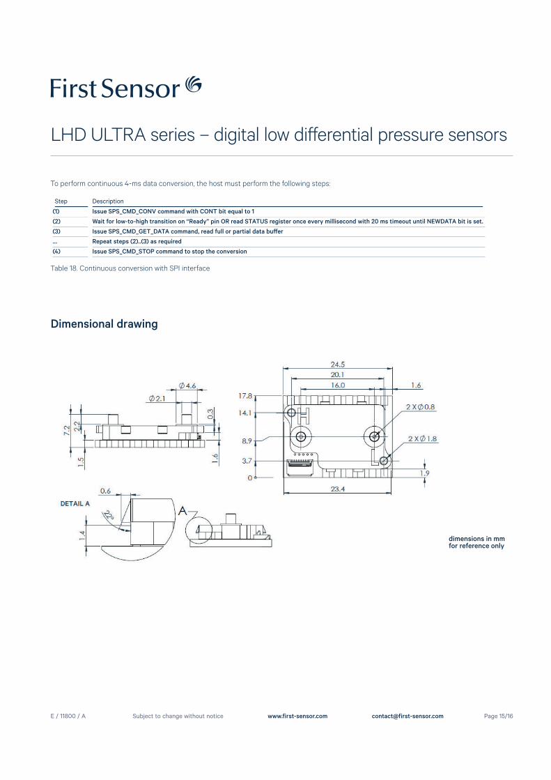
Dimensional drawing
dimensions in mmfor reference only
E / 11800 / A
LHD ULTRA series – digital low diff erential pressure sensors
Page 16/16Subject to change without notice www.first-sensor.com [email protected]
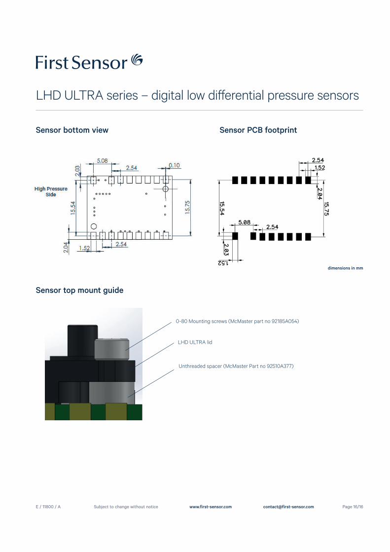
Sensor bottom view Sensor PCB footprint
dimensions in mm
0-80 Mounting screws (McMaster part no 92185A054)
Unthreaded spacer (McMaster Part no 92510A377)
LHD ULTRA lid
Sensor top mount guide