Embed Size (px)
Citation preview

LHCC referee meetingL.Rossi - INFN / Genova CERN - March 19 - 20011
Status of insertable pixelStatus of insertable pixel Layout in 2000 (Dubna layout) Reasons for the change (and boundary
conditions) Design of insertable pixel
layout insertion method service routing and patch panels
Simulation results coverage and resolution material
Road to ECR
LHCC referee meetingL.Rossi - INFN / Genova CERN - March 19 - 20012
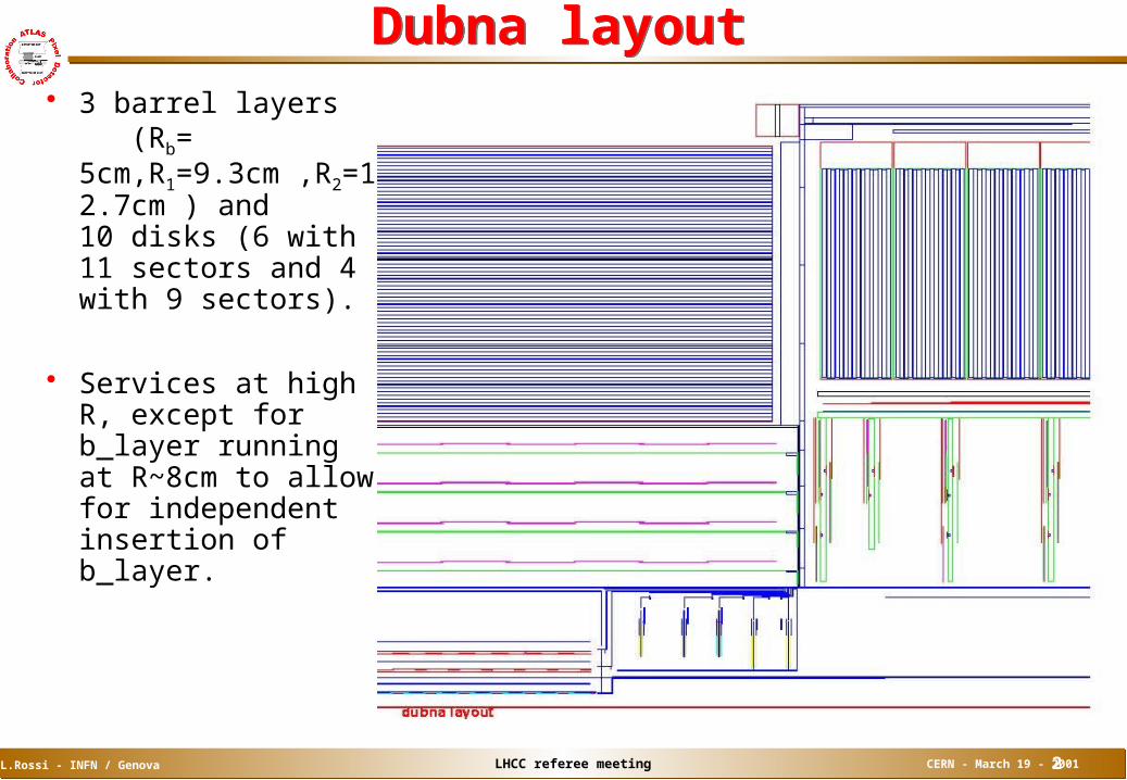
Dubna layout Dubna layout 3 barrel layers
(Rb= 5cm,R1=9.3cm ,R2=12.7cm ) and 10 disks (6 with 11 sectors and 4 with 9 sectors).
Services at high R, except for b_layer running at R~8cm to allow for independent insertion of b_layer.

LHCC referee meetingL.Rossi - INFN / Genova CERN - March 19 - 20013
Reasons for changeReasons for change Rad-hard submissions to DMILL (tested in detail in 2000) revealed
unexpected problems for our FE design. After some trials with DMILL, migration to DSM technology was judged necessary. This has generated a schedule delay of at least 15 months and made impossible (or very risky) to install the pixel inside the barrel ID on the SR building (on 4/2004).
Installing pixel separately from ID gives also more freedom in case of production problems (more likely for a novel detector) and allows easier upgrade & repair (all vertex detectors undergo upgrade sooner or later).

LHCC referee meetingL.Rossi - INFN / Genova CERN - March 19 - 20014
Layout updateLayout update Why we did not propose it before?
mechanics more difficult (and a lot of redesign if half-shelled) more material (services at lower radius, more massive mechanics) conflicts with SCT (inner bore + alignment)
A solution was found to keep the present design approach (shell and disks) and install pixel in absence of the beam pipe section just outside the barrel, i.e. break vacuum (as in long shutdown scenario), remove section of b_pipe,
and install pixel during ~2 months (<< long shutdown timescale)
The layout redesign implies some shrinkage after envelope agreement with SCT [smaller radii by ~5mm (R1=8.7cm ,R2=12.2cm) and less and smaller disks (3+3, 8 sectors each)] less modules to build (2094 1744; i.e. – 17%) less robust PR at large . some (~2%) acceptance losses for 3-hit coverage.
Further optimization difficult without loosing one hitshrunk from outside (SCT bore) and inside (beam pipe)
and in-the-middle (requirement of b_layer independently extractable rails)

LHCC referee meetingL.Rossi - INFN / Genova CERN - March 19 - 20015
Insertable layoutInsertable layout All services go at low radius up to the barrel end b_layer services all out on one side
keep independent b_layer insertion/extraction
1400m
m=2=2
=2.5=2.5

LHCC referee meetingL.Rossi - INFN / Genova CERN - March 19 - 20016
Barrel design also updated to slightly increase clearance between staves safer mount/dismount and pigtail routing (clearances~1.5mm (1 for
b_layer)) Flex -hybrid module (as opposed to MCMD) adopted also for b_layer

LHCC referee meetingL.Rossi - INFN / Genova CERN - March 19 - 20017
Design of insertable pixelDesign of insertable pixel A permanent CF tube is installed with ID
this allows to slide in pixel+services sliding in through the beam pipe flange
SCT
TRTTRT
34
50m
m
3400mm (end-plug face)
PP0Overlap regionZ=[750,1070]
PP1In End-Plug
Z=3400
Length of service panelPixel + Pigtails
795mm (Barrel Tube half length)
Pixel Frame is 1400mm longWithout pigtails
Side C Side A

LHCC referee meetingL.Rossi - INFN / Genova CERN - March 19 - 20018
The insertion process is done when the Forward Calorimeter is retracted and the relative beam pipe section is out.
First the far services and the pixel frame are inserted
Far Services
Far ServicesPixel Frame
Beam pipe support
Inner Detector Bore
Beam pipe
Far Servicesin Quadrants 2.65m
Services need to extend beyond end of Beam pipe support frame to allow termination of overlapping pigtails
Z=3450 (this bears some investigation)500mm
(comfortableHuman-width)
2270mmTo end of Pigtails

LHCC referee meetingL.Rossi - INFN / Genova CERN - March 19 - 20019
Far services terminated, pixel detector inserted
Far Services
Far Services
Terminate Far Services
2270mmTo end of Pigtails
300-500 for Cantileveredsupport
2770mmOver mechanical
supportZ=3450
Far side barrel pigtails need to fold back over frame to give access to PP0
Z=
6220
mm
Z=
5720
Cantilever structure necessary to support beampipe during installation—same as for ID forward installation

LHCC referee meetingL.Rossi - INFN / Genova CERN - March 19 - 200110
Then the near services are connected and slided in
Far ServicesNear Services
3400 (end of support tube)
Support wire at 3450 re-attachedFrame end just inside tube(Frame end to PP0 gap is 50mm)
(2.65m + 50mm)
2.7m6.1
m
Far Services
Termination to B-Layer services occurs inbound of Support wire

LHCC referee meetingL.Rossi - INFN / Genova CERN - March 19 - 200111
Assembly order require connections at different locations (PP0 and PP1) but simplifies PP2
Pigtail
PP1
“Type I” 2.7m
“Type II” 3.2m to PPB2
PPB1
Pixel Volume
Patch PPF1
To PP3
PP0 Location
PPB2
No Longer Used
Voltage drop on low mass cables becomes more challenging.Voltage drop on low mass cables becomes more challenging.Timed well with DSM change (everything changes)Timed well with DSM change (everything changes)

LHCC referee meetingL.Rossi - INFN / Genova CERN - March 19 - 200112
The b_layer must be clam-shelled as it does not pass through the beam pipe flange without opening. the b_layer can (in principle) be inserted without breaking the vacuum.
Far Services
1.2m
Far Services
TOP View
VerticalSupport
Halves are inserted around wire--requiredtooling is not shown
Halves are closed and fixed together
B-layer is inserted into Pixel Frame using samerails in pixels as for baseline

LHCC referee meetingL.Rossi - INFN / Genova CERN - March 19 - 200113
Cartoon of b_layer insertion
Preliminary design of tooling structures is consistent with space available now. Length of 1.2m required
Halves are held together by longitudinal actuation

LHCC referee meetingL.Rossi - INFN / Genova CERN - March 19 - 200114
Finish of b_layer installation
Far Services
Far Services
To terminate the services to the B-layer, and the rest of the detector, the detector must be withdrawn to gain access
B-layer services are terminated first as they will beobscured by the rest of the pixel services
The B-Layer is then pushed into the frame into its final position. Depending on the length of the Pigtails on theB-layer, this step may be avoided
B-layer Services

LHCC referee meetingL.Rossi - INFN / Genova CERN - March 19 - 200115
Patch Panel Octant Name
Barrel Layers 1&2 Disk
Tube Total
6-Module Bundle
7-Module Bundles
Bundle Total
Staves Serviced
Sectors Serviced
1A 3 2 5 (3+6)=9 6 15 12 3
2A 3 1 4 (3+6)=9 6 15 12 3
3A 3 2 5 (3+5)=8 5 13 10 3
4A 3 1 4 (3+6)=9 6 15 12 3
5A 3 2 5 (3+6)=9 6 15 12 3
6A 2 1 3 (3+5)=8 5 13 10 3
7A 3 2 5 (3+6)=9 6 15 12 3
8A 3 1 4 (3+6)=9 6 15 12 3
1C 3 1 4 (3+5)=8 6 15 10 3
2C 3 2 5 (3+6)=9 6 15 12 3
3C 2 1 3 (3+6)=9 5 13 12 3
4C 3 2 5 (3+6)=9 6 15 12 3
5C 3 1 4 (3+6)=9 6 15 12 3
6C 3 2 5 (3+5)=8 5 13 10 3
7C 3 1 4 (3+6)=9 6 15 12 3
8C 3 2 5 (3+6)=9 6 15 12 3
1CBL 2 4 4 8 4
2CBL 3 6 6 12 6
3CBL 3 6 6 12 6
4CBL 3 6 6 12 6
Sid
e A
Sid
e C
Sid
e C
B
-La
ye
r
7A6A
8A
2A
4A 1
A
5A
3A6C7C
5C
3C
1C 4
C
8C
2C
4CBL
2CBL
3CBL
1
1CBL
Needs update for new stave count (90)
Services routing (octants)

LHCC referee meetingL.Rossi - INFN / Genova CERN - March 19 - 200116
PP0PP0
Radius of PP0 is approximately 180mm Starts at Z=750 and goes to Z=1070 (50mm gap between PP0 and
Frame)
Z_400.7Z_440
65
0
49
5
58
0
R_190
R_90
10
0m
m
205mm
260mm
50mm120mm
Z_7
00
130mm
50mm
30mm
160mmBi-Stave Assy
6X 7X
370mm
En
d o
f Pix
els+
Pig
tails
Z_1
070
End of Pixel Frame

LHCC referee meetingL.Rossi - INFN / Genova CERN - March 19 - 200117
Rail system on support tubeRail system on support tube
Vee and Flat rails were chosen to provide pseudo-kinematic support for the detector during delivery to the support points
Rails are used only for delivery, not support

LHCC referee meetingL.Rossi - INFN / Genova CERN - March 19 - 200118
Support tube mock-upSupport tube mock-up
Sufficient space acquired in old Bevatron Generator Room (@LBNL) Enough space to simulate entire assembly sequence
Mockup in three pieces to simulate independent parts of tube Goal is for full length of entire tube to simulate all installation scenarios Detector rails are removable, should modification be necessary

LHCC referee meetingL.Rossi - INFN / Genova CERN - March 19 - 200119
Scope of tube mock-upScope of tube mock-up Mass and Envelope Geometry of final detector Frame
Attempting for similar friction as well At least two full quadrants of “dummy” service panels
Initially 1-quadrant, both sides, eventually half of all services At least two octants (both sides) of mechanically accurate
connectionNeeded for installation simulation
At least one octant of electrically active service connectionsThis is to provide verification that terminations stay terminated through
procedureMight prove useful for thermal mockup
Provision for Dummy B-Layer installationRequires also mechanical connections for installation simulation
Expected to be ready (tube + services) by end of March

LHCC referee meetingL.Rossi - INFN / Genova CERN - March 19 - 200120
Simulation resultsSimulation results Coverage
first disk cannot come too close to barrel end (service routing)
Barrel-to-disk two hit hole
Assume all tracks Assume all tracks coming from (0.0.0)coming from (0.0.0)

LHCC referee meetingL.Rossi - INFN / Genova CERN - March 19 - 200121
Geometric hit losses (not including electronics , dead channels)
Vertex smearing includedVertex smearing included

LHCC referee meetingL.Rossi - INFN / Genova CERN - March 19 - 200122
200 GeV 200 GeV Resolution does not change appreciably
e.g. in b_layer

LHCC referee meetingL.Rossi - INFN / Genova CERN - March 19 - 200123
200 GeV 200 GeV Transverse impact parameter slightly improves
MCMD --> flex (51.5 to 50m pixel size), smaller radii of layers 1&2 and larger stave tilt angle
Longitudinal i.p. worsens at high less disks and algorithm not yet tuned for long clusters in b_layer

LHCC referee meetingL.Rossi - INFN / Genova CERN - March 19 - 200124
1 GeV 1 GeV No change of i.p. resolution vs Dubna layout, sensible change vs
physics TDR layout mostly due to increase of the b_layer radius (4 -> 5cm) beam pipe X0 (1mm Be -->1.6mm Be) and radius (24 -->38mm) increase
not yet included in simulation (new beam pipe not yet released).

LHCC referee meetingL.Rossi - INFN / Genova CERN - March 19 - 200125
MaterialMaterial increase mostly due to support tube + services at low radius
mean increase up to ~2 is ~0.6%X0

LHCC referee meetingL.Rossi - INFN / Genova CERN - March 19 - 200126
Material with less layersMaterial with less layers We will likely start-up with 2 layers

LHCC referee meetingL.Rossi - INFN / Genova CERN - March 19 - 200127
Low-energy tails in EM calorimeter spectraLow-energy tails in EM calorimeter spectra Study of effects on EMC and on b_tagging just started
Tails event fraction with Erec < 0.92 Etrue
Layout Tails =0.3 Tails =2.4
Physics TDR 9.5 0.6% 3.6 0.6% Insertable 11.3 0.7% 9.6 0.9%
Vertex spread includedEvents over full and =0.025 (1 cell)
Electrons ET =10 GeV = 2.4
Normalised to same number of events
LHCC referee meetingL.Rossi - INFN / Genova CERN - March 19 - 200128
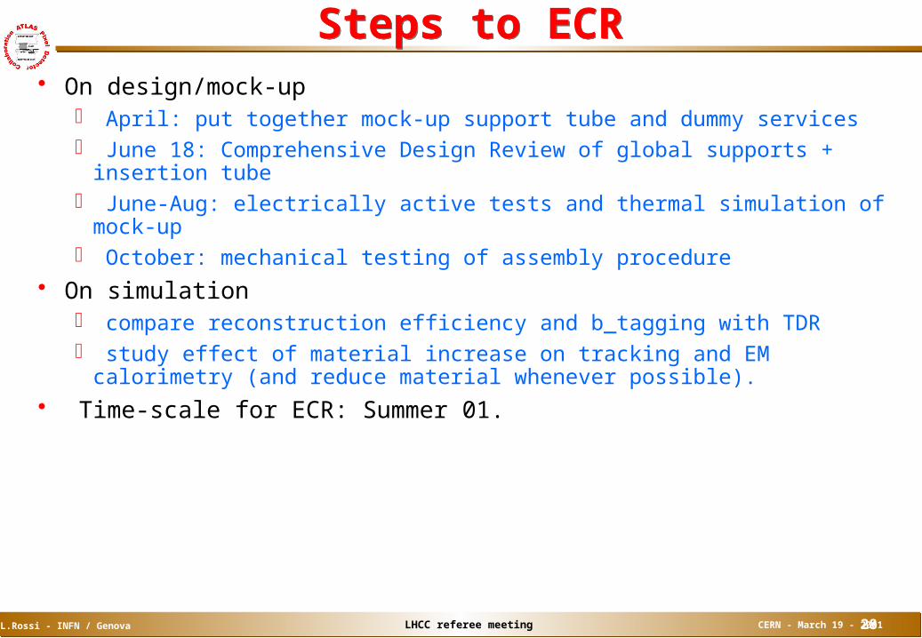
Steps to ECRSteps to ECR On design/mock-up
April: put together mock-up support tube and dummy services June 18: Comprehensive Design Review of global supports + insertion
tube June-Aug: electrically active tests and thermal simulation of mock-up October: mechanical testing of assembly procedure
On simulation compare reconstruction efficiency and b_tagging with TDR study effect of material increase on tracking and EM calorimetry (and
reduce material whenever possible). Time-scale for ECR: Summer 01.