Embed Size (px)
Citation preview

LG&E/KU – Ghent Station Phase II Air Quality Control Study Air Quality Control Validation Report February 16, 2010 Revision C – Issued For Project Use B&V File Number 41.0803

LG&E/KU – Ghent Station Air Quality Control Validation Report Table of Contents
February 2011 TC-1 168908.41.0803
Table of Contents
Acronym List ...............................................................................................................AL-1
1.0 Introduction.......................................................................................................... 1-1
2.0 Facility Description.............................................................................................. 2-1
2.1 Ghent- Units 1, 2, 3, and 4 ....................................................................... 2-1
3.0 Emission Target Basis.......................................................................................... 3-1
4.0 Site Visit Summary .............................................................................................. 4-1
4.1 Site Visit Observations and AQC ............................................................ 4-1
5.0 Selected Air Quality Control Technology ........................................................... 5-1
5.1 Technology Descriptions ......................................................................... 5-2
5.1.1 Selective Catalytic Reduction System....................................... 5-2
5.1.2 Pulse Jet Fabric Filter ................................................................ 5-4
5.1.3 Powdered Activated Carbon Injection....................................... 5-6
5.1.4 Sorbent Injection ....................................................................... 5-9
5.1.5 CO Reduction Technologies...................................................... 5-9
5.2 Unit by Unit Summary of AQC Selection ............................................. 5-10
5.2.1 Ghent Unit 1 ............................................................................ 5-10
5.2.2 Ghent Unit 2 ............................................................................ 5-12
5.2.3 Ghent Units 3 and 4................................................................. 5-14
6.0 Validation Analyses ............................................................................................. 6-1
6.1 Draft System Analysis ............................................................................. 6-1
6.1.1 Unit 1 ......................................................................................... 6-2
6.1.2 Unit 2 ......................................................................................... 6-5
6.1.3 Unit 3 ......................................................................................... 6-9
6.1.4 Unit 4 ....................................................................................... 6-12
6.1.5 Draft System Transient Design Pressures ............................... 6-15
6.2 Auxiliary Electrical System Analysis .................................................... 6-15
6.3 AQC Mass Balance Analysis................................................................. 6-17
6.4 Reagent Impact Analysis ....................................................................... 6-17
6.5 Chimney Analysis.................................................................................. 6-18
6.6 Constructability Analysis....................................................................... 6-18
6.6.1 Unit 1 Arrangement ................................................................. 6-19
6.6.2 Unit 2 Arrangement ................................................................. 6-21
6.6.3 Unit 3 Arrangement ................................................................. 6-26
6.6.4 Unit 4 Arrangement ................................................................. 6-28
6.7 Truck/Rail Traffic Analysis ................................................................... 6-30

LG&E/KU – Ghent Station Air Quality Control Validation Report Table of Contents
February 2011 TC-2 168908.41.0803
Table of Contents (Continued)
7.0 Conclusion ........................................................................................................... 7-1
Appendix A Conceptual Sketches
Appendix B Flow Biasing Options
Tables
Table 2-1. Existing Ghent Plant Facilities ...................................................................... 2-4
Table 3-1. Primary Design Emission Targets ................................................................. 3-2
Table 5-1. AQC Technologies ........................................................................................ 5-1
Table 5-2. Unit 1– AQC Selection................................................................................ 5-10
Table 5-3. Unit 2 – AQC Selection............................................................................... 5-12
Table 5-4. Units 3 and 4 – AQC Technology Selection ............................................... 5-14
Table 6-1. Unit 1 Future Draft System Characteristics at MCR..................................... 6-3
Table 6-2. Unit 1 New Booster Fan MCR and Recommended Test Block Conditions ................................................................................................ 6-4
Table 6-3. Unit 2 Future Draft System Characteristics at MCR..................................... 6-7
Table 6-4. Unit 2 New Booster Fan MCR and Recommended Test Block Conditions ................................................................................................ 6-8
Table 6-5. Unit 3 Future Draft System Characteristics at MCR................................... 6-10
Table 6-6. Unit 3 New ID Fan MCR and Recommended Test Block Conditions........ 6-11
Table 6-7. Unit 4 Future Draft System Characteristics at MCR................................... 6-13
Table 6-8. Unit 4 New ID Fan MCR and Recommended Test Block Conditions....... 6-14
Table 6-9. Sorbents and Reagents Consumption Rates (tph) ....................................... 6-30
Table 7-1. AQC Technologies ........................................................................................ 7-2
Figures
Figure 2-1. Ghent Power Plant Site ................................................................................ 2-2
Figure 2-2. Ghent and Surrounding Area Map ............................................................... 2-3
Figure 5-1. Schematic Diagram of a Typical SCR Reactor............................................ 5-3
Figure 5-2. Pulse Jet Fabric Filter Compartment............................................................ 5-5
Figure 5-3. Activated Carbon Injection System ............................................................. 5-7
Figure 6-1. Unit 1 Future Draft System.......................................................................... 6-2
Figure 6-2. Unit 2 Future Draft System.......................................................................... 6-6
Figure 6-3. Unit 3 Future Draft System.......................................................................... 6-9
Figure 6-4. Unit 4 Future Draft System........................................................................ 6-12

LG&E/KU – Ghent Station Air Quality Control Validation Report Acronym List
December 2010 AL-1 168908.41.0803
Acronym List
AQC Air Quality Control
As Arsenic
Be Beryllium
CAIR Clean Air Interstate Rule
CATR Clean Air Transport Rule
Cd Cadmium
Co Cobalt
Cr Chromium
CS-ESP Cold-side Electrostatic Precipitator
DCS Distributed Control System
DOE Department of Energy
EPA Environmental Protection Agency
EPRI Electric Power Research Institute
ESP Electrostatic Precipitator
H2SO4 Sulfuric Acid
HCl Hydrogen Chloride
Hg Mercury
ID Induced Draft
inw Inch of Water
LNB Low NOx Burners
LV Low Voltage
MACT Maximum Achievable Control Technology
MBtu Million British Thermal Unit
MCC Motor Control Center
Mn Manganese
MSW Municipal Solid Waste
MV Medium Voltage
MWC Medical Waste Combustors
NAAQS National Ambient Air Quality Standard
NFPA National Fire Protection Association
Ni Nickel
NN Neural Network
NOx Nitrogen Oxides
OFA Overfire Air
PAC Powdered Activated Carbon
LG&E/KU – Ghent Station Air Quality Control Validation Report Acronym List
December 2010 AL-2 168908.41.0803
Pb Lead
PJFF Pulse Jet Fabric Filter
PM Particulate Matter
RAT Reserve Auxiliary Transformer
RGFF Reverse Gas Fabric Filters
SAM Sulfuric Acid Mist
Sb Antimony
SBS Sodium Bisulfite
SCR Selective Catalytic Reduction
Se Selenium
SO2 Sulfur Dioxide
SO3 Sulfur Trioxide
tph Tons per Hour
UAT Unit Auxiliary Transformer
VFD Variable Frequency Drives
WFGD Wet Flue Gas Desulfurization

LG&E/KU – Ghent Station Air Quality Control Validation Report Introduction
February 2011 1-1 168908.41.0803
1.0 Introduction
Following the submittal of the Phase I report on July 8, 2010, Black & Veatch
developed scope to further define facility technology options based on the Phase I report.
The purpose of this Phase II air quality control (AQC) validation study is to build upon
the previous fleet-wide, high-level air quality technology review and cost assessment
conducted for six LG&E/KU facilities (Phase I) in order to develop a facility-specific
project definition consisting of a conceptual design and a budgetary cost estimate for
selected AQC technologies (Phase II) for the Ghent Generating Station. The following
AQC technology options have been assessed in this report:
PJFF on Units 1-4.
Sorbent injection (trona/lime/SBS) injection on Unit 2.
SCR on Unit 2.
Powdered activated carbon (PAC) injection on Units 1-4.
Feasibility of neural network (NN) on Units 1-4.
This validation study confirms the feasibility of installing the aforementioned
AQC equipment at Ghent, and presents the supporting considerations, arrangements, and
preliminary validating analyses of the AQC equipment that will be built upon in the next
step of this project to complete the conceptual design and budgetary cost estimate.

LG&E/KU – Ghent Station Air Quality Control Validation Report Facilit y Description
February 2011 2-1 168908.41.0803
2.0 Facility Description
2.1 Ghent- Units 1, 2, 3, and 4 The Ghent Station is located in Carroll County, approximately 9 miles northeast
of Carrolton, Kentucky, on an approximately 1,670 acre site. Ghent Station includes four
pulverized coal fired electric generating units with a gross total generating capacity of
2,107 MW. Ghent Station began commercial operations in 1973.
All four steam generators (boilers) fire high sulfur bituminous coal. Two of the
boilers are manufactured by Combustion Engineering and two by Foster Wheeler. The
Combustion Engineering boilers are tangential-fired, balanced draft forced circulation
boilers, and Foster Wheeler boilers are balanced draft natural circulation boilers. Unit 1
has a gross capacity of 541 MW and is equipped with low NOx burners (LNBs) and
selective catalytic reduction (SCR) for nitrogen oxide (NOx) control; cold-side dry
electrostatic precipitator (ESP) for particulate matter (PM) control; wet flue gas
desulfurization (WFGD) for sulfur dioxide (SO2) control, and lime injection system for
sulfuric acid (H2SO4) and/or sulfur trioxide (SO3) control. Unit 2 has a gross capacity of
517 MW and is equipped with LNBs and overfire air (OFA) for NOx control; hot-side dry
ESP for PM control; and WFGD system for SO2 control, and lime injection system for
H2SO4/SO3 control. Units 3 and 4 have a gross capacity of 523 MW and 526 MW,
respectively, and are equipped with LNBs, OFA, and low-dust SCR for NOx control; hot-
side dry ESP for PM control; wet FGD system for SO2 control, and trona injection system
for H2SO4/SO3 control.
Gypsum, a scrubber by-product, produced at Ghent is stored in the on-site
landfill. Fly ash and bottom ash is sluiced to on-site storage ponds. Black & Veatch is
also involved in a separate study for the transportation of coal combustion products.
Layouts developed for the alternative transport systems will be taken into account during
the Phase II Air Quality Control Study. All four units are cooled using mechanical draft
cooling towers.
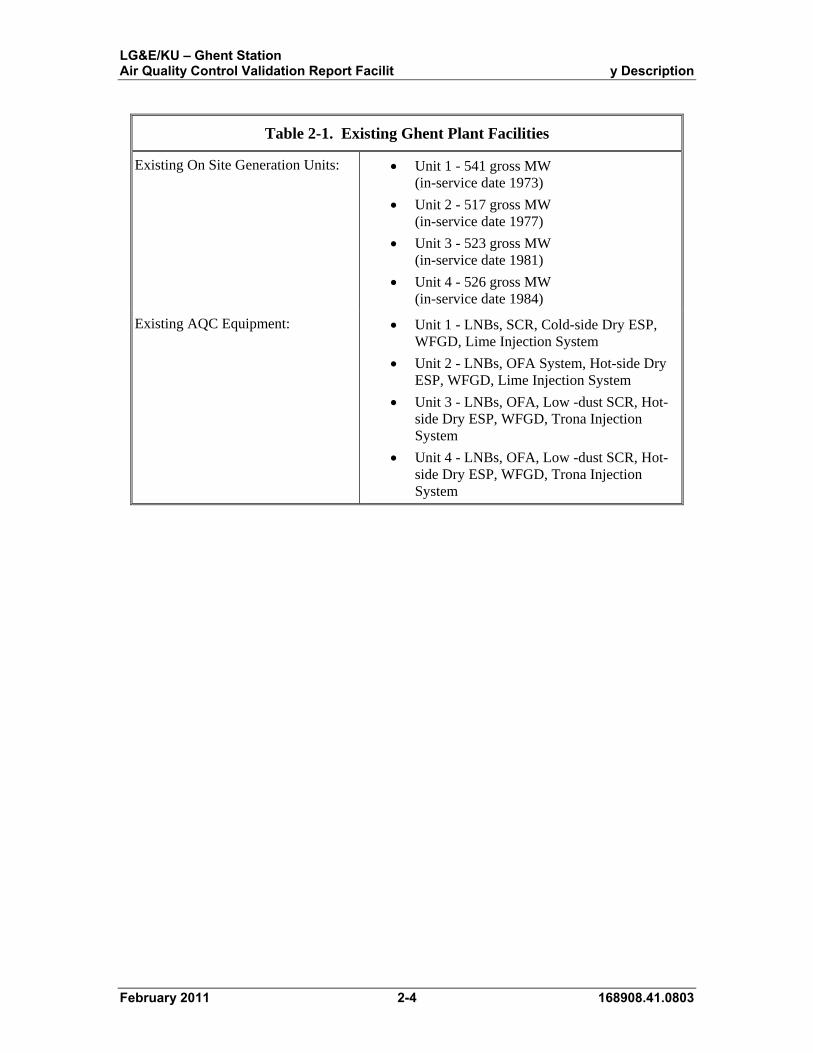
Figures 2-1 and 2-2 illustrate the plant location and Table 2-1 summarizes the
plant’s existing facilities.

LG&E/KU – Ghent Station Air Quality Control Validation Report Facilit y Description
February 2011 2-2 168908.41.0803
NORTH
Figure 2-1. Ghent Power Plant Site

LG&E/KU – Ghent Station Air Quality Control Validation Report Facilit y Description
February 2011 2-3 168908.41.0803
NORTH
SOUTH
Figure 2-2. Ghent and Surrounding Area Map
LG&E/KU – Ghent Station Air Quality Control Validation Report Facilit y Description
February 2011 2-4 168908.41.0803
Table 2-1. Existing Ghent Plant Facilities
Existing On Site Generation Units: Unit 1 - 541 gross MW (in-service date 1973)
Unit 2 - 517 gross MW (in-service date 1977)
Unit 3 - 523 gross MW (in-service date 1981)
Unit 4 - 526 gross MW (in-service date 1984)
Existing AQC Equipment: Unit 1 - LNBs, SCR, Cold-side Dry ESP, WFGD, Lime Injection System
Unit 2 - LNBs, OFA System, Hot-side Dry ESP, WFGD, Lime Injection System
Unit 3 - LNBs, OFA, Low -dust SCR, Hot-side Dry ESP, WFGD, Trona Injection System
Unit 4 - LNBs, OFA, Low -dust SCR, Hot-side Dry ESP, WFGD, Trona Injection System
LG&E/KU – Ghent Station Air Quality Control Validation Report Emission Target Basis
February 2011 3-1 168908.41.0803
3.0 Emission Target Basis
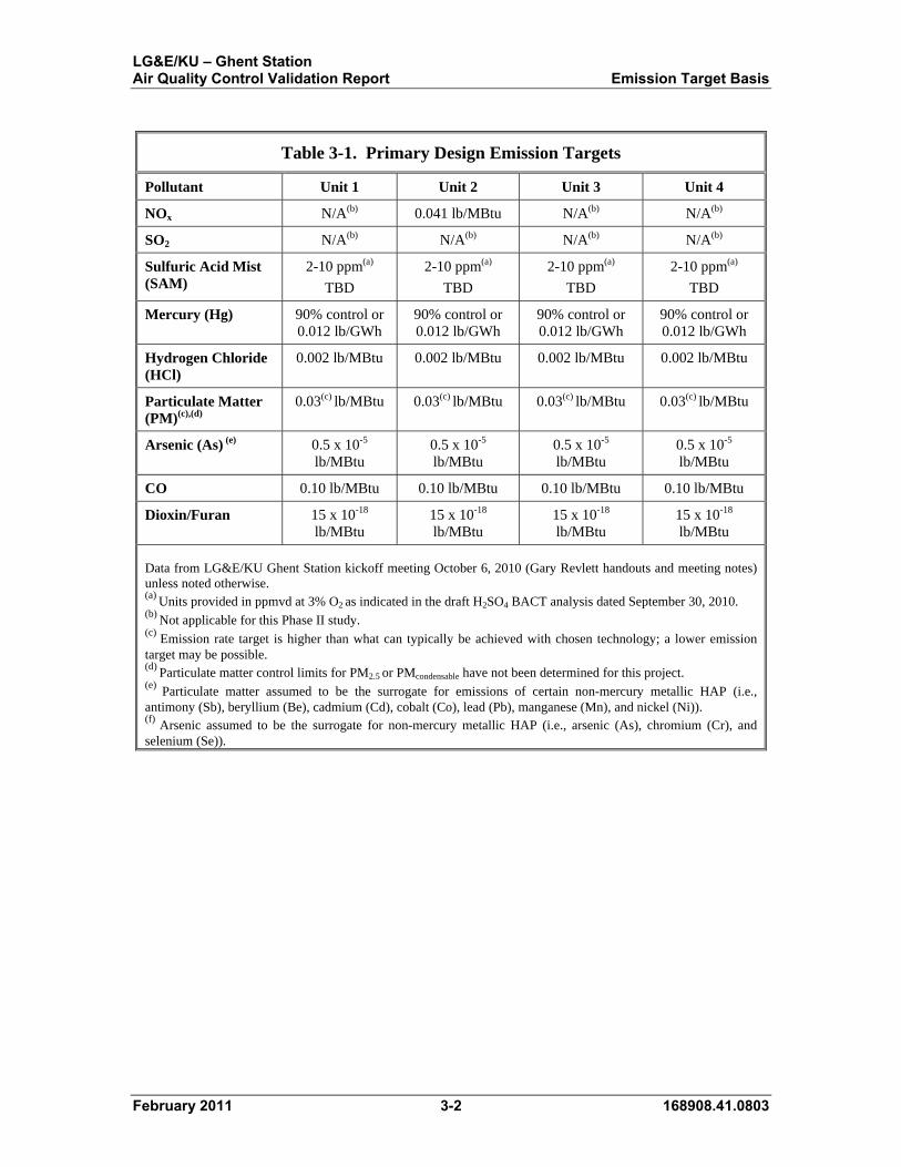
LG&E/KU provided a matrix of estimated requirements under current and future
environmental regulations, as well as a summary implementation schedule of regulatory
programs. Table 3-1 summarizes the future pollution emission targets provided by
LG&E/KU for each unit.
The current regulatory drivers include the NO2 and SO2 National Ambient Air
Quality Standard (NAAQS). On January 22, 2010, the Environmental Protection Agency
(EPA) announced a new 1-hour NO2 NAAQS of 100 ppb. The final rule for the new
hourly NAAQS was published in the Federal Register on February 9, 2010, and the
standard became effective on April 12, 2010. Likewise, on June 2, 2010, EPA
strengthened the primary SO2 NAAQS. EPA established a new 1-hour standard at a level
of 75 ppb and revoked the existing 24-hour and annual standards.
The potential impact of future regulations is the primary driver for both the timing
and extent of environmental controls planned at the LG&E/KU plants. Among the
regulatory drivers are the Utility Maximum Achievable Control Technology (MACT),
and the Clean Air Transport Rule (CATR) -- Clean Air Interstate Rule (CAIR)
replacement to be proposed by the United States EPA by spring 2011 and summer 2011,
respectively.
From this information, LG&E/KU developed specific pollutant emission limit
targets with the intent that the limits would be applied to each unit individually to assess
current compliance and the potential for additional AQC equipment. These regulatory
drivers and their associated emission levels serve as the primary basis used by Black &
Veatch to develop unit-by-unit AQC technology recommendations. For the purposes of
this study, compliance options beyond the addition of new AQC technology (such as fuel
switching, shutdown of existing emission units, development of new power generation,
and emissions averaging scenarios) were not considered.
LG&E/KU – Ghent Station Air Quality Control Validation Report Emission Target Basis
February 2011 3-2 168908.41.0803
Table 3-1. Primary Design Emission Targets
Pollutant Unit 1 Unit 2 Unit 3 Unit 4
NOx N/A(b) 0.041 lb/MBtu N/A(b) N/A(b)
SO2 N/A(b) N/A(b) N/A(b) N/A(b)
Sulfuric Acid Mist (SAM)
2-10 ppm(a)
TBD
2-10 ppm(a)
TBD
2-10 ppm(a)
TBD
2-10 ppm(a)
TBD
Mercury (Hg) 90% control or 0.012 lb/GWh
90% control or 0.012 lb/GWh
90% control or 0.012 lb/GWh
90% control or 0.012 lb/GWh
Hydrogen Chloride (HCl)
0.002 lb/MBtu 0.002 lb/MBtu 0.002 lb/MBtu 0.002 lb/MBtu
Particulate Matter (PM)(c),(d)
0.03(c) lb/MBtu 0.03(c) lb/MBtu 0.03(c) lb/MBtu 0.03(c) lb/MBtu
Arsenic (As) (e) 0.5 x 10⁻⁵ lb/MBtu
0.5 x 10⁻⁵ lb/MBtu
0.5 x 10⁻⁵ lb/MBtu
0.5 x 10⁻⁵ lb/MBtu
CO 0.10 lb/MBtu 0.10 lb/MBtu 0.10 lb/MBtu 0.10 lb/MBtu
Dioxin/Furan 15 x 10-18 lb/MBtu
15 x 10-18 lb/MBtu
15 x 10-18 lb/MBtu
15 x 10-18 lb/MBtu
Data from LG&E/KU Ghent Station kickoff meeting October 6, 2010 (Gary Revlett handouts and meeting notes) unless noted otherwise. (a) Units provided in ppmvd at 3% O2 as indicated in the draft H2SO4 BACT analysis dated September 30, 2010. (b) Not applicable for this Phase II study. (c) Emission rate target is higher than what can typically be achieved with chosen technology; a lower emission target may be possible. (d) Particulate matter control limits for PM2.5 or PMcondensable have not been determined for this project. (e) Particulate matter assumed to be the surrogate for emissions of certain non-mercury metallic HAP (i.e., antimony (Sb), beryllium (Be), cadmium (Cd), cobalt (Co), lead (Pb), manganese (Mn), and nickel (Ni)). (f) Arsenic assumed to be the surrogate for non-mercury metallic HAP (i.e., arsenic (As), chromium (Cr), and selenium (Se)).
LG&E/KU – Ghent Station Air Quality Control Validation Report Site Visit Summary
February 2011 4-1 168908.41.0803
4.0 Site Visit Summary
The following section describes the existing site conditions and site visit observations for the Ghent Generating Station.
4.1 Site Visit Observations and AQC The following observations are from the October 6-7, 2010 site visit and
summarize the site and equipment constraints. The following excerpts are from the October 22, 2010, site visit meeting memo that focused specifically on installing the specified AQC equipment.
Emissions of SO2 should not be a problem for the Ghent units since the
existing FGDs basically achieve +98% removal on the units and the air
dispersion modeling shows that they require 96% removal on a plant
average. Thus, no modification of the FGDs is required.
Hg is an issue at Ghent. However, LG&E/KU hopes that with the addition
of an SCR on Unit 2, acceptable Hg control may be achieved without
additional modifications.
The hot-side ESPs are currently being used either for ash scavenging or
because the existing SCRs are the low-dust type. B&V noted that a
change in catalyst could convert the SCRs to operate in high-dust
conditions if the possibility of lower catalyst life is acceptable.
The area and facilities for dry ash conversion and ash handling need to be
considered with this study. LG&E/KU commented that B&V had
previously completed an ash handling study and that the AQC study must
be coordinated with the plans developed in the ash handling study.
B&V may consider designing the Unit 2 SCR as high-dust units from the
onset, allowing deletion of the existing ESPs at Unit 2 if warranted by
congestion and construction difficulties.
LG&E/KU would like to sell fly ash on an opportunistic basis, but is not
necessarily tied to the existing ESPs. Saleable fly ash would require
“scalping” of the fly ash upstream of PAC injection and require the
retention and use of the existing ESPs.
LG&E/KU prefers no new axial fans and prefers the existing axial fans, if
re-used, be located downstream of the PJFFs.
B&V to investigate a refined layout for Unit 3 PJFF that would reduce the
ductwork runs indicated in the Phase I study.

LG&E/KU – Ghent Station Air Quality Control Validation Report Site Visit Summary
February 2011 4-2 168908.41.0803
The courtyard area between Units 2 and 3 can be used for siting new
equipment. The various maintenance shops on the south side of the
courtyard could be relocated. There is no “sacred ground” onsite that must
be avoided in locating new facilities. However, retention or re-
establishment of the ground level breezeway and the overhead skyway
between Units 2 and 3 is desirable.
B&V believes it will likely not be feasible to reuse/upgrade the existing
induced draft (ID) fans to avoid the addition of new booster or ID fans.
Physical constraints on routing duct to and from the existing ID inlet fans
is problematic. Locating the PJFFs to protect all of the existing ID fans is
not practical in all cases, even for the axial fans at Units 3 and 4. The Unit
3 fans can be incorporated into the revised AQC system, but only in a
location that may not be beneficial. B&V fan experts will review this, but
new ID fans or booster fans are expected to be required for all units.
Unit 1:
Sorbent injection will need to be relocated in the duct work to near
the inlet of the PJFF. LG&E/KU questioned whether the PJFF
vendors would be willing to offer SO3 guarantees based on sorbent
injection. B&V noted that if the vendor is awarded both sorbent
injection and the PJFF as a single package he will likely offer some
guarantees, but the specific level will have to be negotiated.
Concern was expressed with the elevated PJFF for Unit 1 being
located close to the Unit 2 cooling tower. B&V will investigate and
provide opinions on the overall affect of the new structures on
cooling tower performance and level of icing that could result.
If the impact to performance warrants it, it was discussed that a
couple cells could be added to the east end of the tower to increase
the overall tower capacity or allow impacted cells to be taken out
of service.
Alternate arrangements at Unit 1 appear very limited at this time.
LG&E/KU asked about relocating Unit 2’s cooling tower to make
more room for Unit 1 PJFF. The major issue with that approach is
where to relocate the cooling tower. The potential of locating the
new cooling tower towards the river or to the east of Unit 1’s
cooling tower was discussed. Any new construction towards the
river, either relocating the Unit 2 cooling tower or the plant reagent
piperack, would likely trigger permit concerns with the COE.
LG&E/KU – Ghent Station Air Quality Control Validation Report Site Visit Summary
February 2011 4-3 168908.41.0803
Building a new tower in the “rock pile” area (formerly the
limestone storage area east of the plant) was also discussed.
Routing of the underground circulating water lines potentially
would be a major issue.
Unit 2:
Because of the high level of congestion in the existing arrangement
at Unit 2, plus the need to add a PJFF, B&V considered three
alternatives for the SCR location at Unit 2. Two alternatives
(Alternates 1 & 3) include split SCR’s – two separate reactors, one
for each ESP train, with the only difference between the
alternatives being the location of the west side SCR.
Alternate 1 locates the west SCR in the area just west of the west
ID fan and the east SCR above the tower support for the Unit 1
SCRs. The area west of the ID fans appears sufficiently open to
allow construction of a tower support for the SCR. The advantage
of this arrangement is the short runs of ductwork required, and the
SCR reactor box location can be reached by a crane set up in the
area located immediately south of the abandoned Unit 2 chimney.
Alternate 3 locates the west SCR along the west side of the Unit 2
boiler structure and the east SCR in the same location as Alternate
1. The approach suggested in the Phase 1 study of locating both
split SCRs on the west side of the boiler structure would be
problematic because of the difficulty of routing duct work from
east side Unit 2 duct to the courtyard and back.
Alternate 2 is similar to that used for the Unit 1 SCR, with a
combined SCR located above the ESPs. However, the area beneath
the SCRs in Alternate 2 is very congested, making foundation
design and installation extremely difficult. Moreover, the lack of
nearby open area adjacent to the SCR locations will limit crane
access and greatly complicate constructability. Assuming sufficient
free area is found to accommodate the necessary foundations,
Alternate 1 is more favorable to construction and the most likely
option.
Low dust SCRs will be assumed for Unit 2 unless elimination of
the existing ESPs is warranted for some other reason.

LG&E/KU – Ghent Station Air Quality Control Validation Report Site Visit Summary
February 2011 4-4 168908.41.0803
LG&E/KU has previous studies which propose locating the SCR
modules in the courtyard on the west side of the Unit 2 boiler
structure. LG&E/KU offered to provide these studies to B&V.
The Unit 2 PJFF is assumed to be located north of the existing
ESPs and ductwork. A short temporary bypass ductwork can be
installed between the air heater outlet duct and the ductwork to the
scrubber inlet. This would allow the large section of ductwork
located north of the bypass to be demolished and the PJFF installed
in its place while Unit 2 is on line. The completed PJFF would be
tied into the system during an outage. The new booster or ID fans
for Unit 2 (not shown on the arrangement sketches) would
tentatively be located at the west (downstream) end of the new
PJFF.
Unit 3:
The preliminary arrangement sketches show the PJFF location in
the courtyard, requiring relocation of the maintenance shop.
LG&E/KU has some ideas where the shop could be relocated. As
currently configured, new booster or ID fans could be added south
of the PJFF without impacting the existing tanks south of the shop.
The skyway connecting Units 2 and 3 would need to be
temporarily removed while the PJFF is installed. The skyway
would then be modified to route around the south side of the PJFF
and reconnect to Unit 3. It may also be possible to modify the
skyway to provide access from the turbine buildings to the PJFF.
To avoid re-routing of the significant amount of interconnecting
pipe located in the ground level breezeway between units, the PJFF
would be designed to span over this piping and allow the
breezeway structure to remain in place, if practical.
Unit 4:
The most likely location for the new PJFF is between the existing
Unit 4 ESP area and the Unit 3 cooling tower as shown on the
sketch. This location avoids the large 96” diameter circulating
water pipelines, the water well, and most of the underground
utilities in the area.

LG&E/KU – Ghent Station Air Quality Control Validation Report Site Visit Summary
February 2011 4-5 168908.41.0803
The ID fans currently being installed at Unit 4 would be difficult to
incorporate into the proposed ductwork configuration running
between the existing ductwork tie in and the new PJFF and back,
as shown on the arrangement sketches. A more favorable
configuration may be accomplished by locating the new ID fans
near the PJFF. The new fans would be sized to replace the current
ID fans. New ID fans in this location would allow relatively easy
connection directly to the ductwork at the FGD inlet.
LG&E/KU expressed general agreement with the arrangement as
discussed for Unit 4. An alternate version of the Unit 4
arrangement sketch was developed to more closely depict the
arrangement discussed.

LG&E/KU – Ghent Station Air Quality Control Validation Report Selected AQC Technology
February 2011 5-1 168908.41.0803
5.0 Selected Air Quality Control Technology
The following sections present a general description of the AQC technologies
considered for Ghent, as well as a unit by unit discussion of the key attributes of the
technologies and special considerations for their application and arrangement at the
affected units. Table 5-1 presents the selected AQC technologies that were considered in
the validation process.
Table 5-1. AQC Technologies
Unit 1 Unit 2 Unit 3 Unit 4
NOx Control Existing SCR New SCR Existing SCR Existing SCR
SO2 Control Existing WFGD Existing WFGD Existing WFGD Existing WFGD
PM Control New PJFF New PJFF New PJFF New PJFF
HCl Control Existing WFGD and Existing Sorbent Injection
Existing WFGD and New Sorbent Injection
Existing WFGD and Existing Sorbent Injection
Existing WFGD and Existing Sorbent Injection
CO Control New NN New NN New NN New NN
SO3 Control Existing Sorbent Injection
New Sorbent Injection
Existing Sorbent Injection
Existing Sorbent Injection
Hg Control New PAC Injection New PAC Injection New PAC Injection
New PAC Injection
Dioxin/Furan Control
New PAC Injection New PAC Injection New PAC Injection
New PAC Injection
Fly Ash Sales Existing CS-ESP Existing HS-ESP Existing HS-ESP Existing HS-ESP
CS-ESP = Cold-Side Electrostatic Precipitator. HS-ESP = Hot-Side Electrostatic Precipitator.

LG&E/KU – Ghent Station Air Quality Control Validation Report Selected AQC Technology
February 2011 5-2 168908.41.0803
5.1 Technology Descriptions The following sections provide a brief general description of the proposed AQC
technologies.
5.1.1 Selective Catalytic Reduction System
In an SCR system, ammonia is injected into the flue gas stream just upstream of a
catalytic reactor. The ammonia molecules in the presence of the catalyst dissociate a
significant portion of the NOx into nitrogen and water.
The aqueous ammonia is received and stored as a liquid. The ammonia is
vaporized and subsequently injected into the flue gas by compressed air or steam as a
carrier. Injection of the ammonia must occur at temperatures above 600 F to avoid
chemical reactions that are significant and operationally harmful. Catalyst and other
considerations limit the maximum SCR system operating temperature to 840 F.
Therefore, the system is typically located between the economizer outlet and the air
heater inlet. The SCR catalyst is housed in a reactor vessel, which is separate from the
boiler. The conventional SCR catalysts are either homogeneous ceramic or metal
substrate coated. The catalyst composition is vanadium-based, with titanium included to
disperse the vanadium catalyst and tungsten added to minimize adverse SO2 and SO3
oxidation reactions. An economizer bypass may be required to maintain the reactor
temperature during low load operation. This will reduce boiler efficiency at lower loads.
The SCR process is a complex system. The SCR requires precise NOx-to-
ammonia distribution in the presence of the active catalyst site to achieve current BACT
levels. In the past, removal efficiencies were the measure of catalyst systems because of
extremely high inlet NOx levels. Current technology SCR systems do not use removal
efficiency as a primary metric because the current generation of LNB/OFA systems limits
the amount of NOx available for removal. Essentially, as NOx is removed through the
initial layers of catalyst, the remaining layers have difficulty sustaining the reaction.
A number of alkali metals and trace elements (especially arsenic) poison the
catalyst, significantly affecting reactivity and life. Other elements such as sodium,
potassium, and zinc can also poison the catalyst by neutralizing the active catalyst sites.
Poisoning of the catalyst does not occur instantaneously, but is a continual steady process
that occurs over the life of the catalyst. As the catalyst becomes deactivated, ammonia
slip emissions increase, approaching design values. As a result, catalyst in a SCR system
is consumable, requiring periodic replacement at a frequency dependent on the level of
catalyst poisoning. However, effective catalyst management plans can be implemented
that significantly reduce catalyst replacement requirements.

LG&E/KU – Ghent Station Air Quality Control Validation Report Selected AQC Technology
February 2011 5-3 168908.41.0803
There are two SCR system configurations that can be considered for application on pulverized coal boilers: high dust and tail end. A high dust application locates the SCR system before the particulate collection equipment, typically between the economizer outlet and the air heater inlet. A tail end application locates the catalyst downstream of the particulate and FGD control equipment. The high dust application requires the SCR system to be located between the economizer outlet and the air heater inlet in order to achieve the required optimum SCR
operating temperature of approximately 600° to 800 F. This system is subject to high
levels of trace elements and other flue gas constituents that poison the catalyst, as previously noted. The tail end application of SCR would locate the catalyst downstream of the particulate control and FGD equipment. Less catalyst volume is needed for the tail end application, since the majority of the particulate and SO2 (including the trace elements that poison the catalyst) have been removed. However, a major disadvantage of this alternative is a requirement for a gas-to-gas reheater and supplemental fuel firing to achieve sufficient flue gas operating temperatures downstream of the FGD operating at
approximately 125 F. The required gas-to-gas reheater and supplemental firing
necessary to raise the flue gas to the sufficient operating temperature are costly. The higher front end capital costs and annual operating cost for the tail end systems present higher overall costs compared to the high dust SCR option with no established emissions control efficiency advantage. Figure 5-1 shows a schematic diagram of SCR.
Figure 5-1. Schematic Diagram of a Typical SCR Reactor
Space For Future Catalyst and Soot Blower Addition
Gas Flow Distribution
Devices
Sonic Horns
Vaporized Ammonia
Flue Gas toAir Heater
Catalyst
Temperature Measurement Grid
Tuning/Monitoring Grid Bypass Damper
Isolation Dampers
Economizer Bypass

LG&E/KU – Ghent Station Air Quality Control Validation Report Selected AQC Technology
February 2011 5-4 168908.41.0803
5.1.2 Pulse Jet Fabric Filter
Pulse jet fabric filters (PJFFs) have been used for over 20 years on existing and
new coal fired boilers and are media filters through which flue gas passes to remove the
particulate. The success of FFs is predominately due to their ability to economically
meet the low particulate emission limits for a wide range of particulate operations and
fuel characteristics. Proper application of the PJFF technology can result in clear stacks
(generally less than 5 percent opacity) for a full range of operations. In addition, the
PJFF is relatively insensitive to ash loadings and various ash types, offering superb coal
flexibility.
FFs are the current technology of choice when low outlet particulate emissions or
Hg reduction is required for coal fired applications. FFs collect particle sizes ranging
from submicron to 100 microns in diameter at high removal efficiencies. Provisions can
be made for future addition of activated carbon injection to enhance gas phase elemental
Hg removal from coal fired plants. Some types of fly ash filter cakes will also absorb
some elemental Hg.
FFs are generally categorized by type of cleaning. The two predominant cleaning
methods for utility applications are reverse gas and pulsejet. Initially, utility experience
in the United States was almost exclusively with Reverse Gas Fabric Filters (RGFF).
Although they are a very reliable and effective emissions control technology, RGFFs
have a relatively large footprint, which is particularly difficult for implementation. PJFFs
can be operated at higher flue gas velocities and, as a result, have a smaller footprint.
The PJFF usually has a lower capital cost than a RGFF and matches the performance and
reliability of a RGFF. As a result, only PJFFs will be considered further.
Cloth filter media is typically sewn into cylindrical tubes called bags. Each PJFF
may contain thousands of these filter bags. The filter unit is typically divided into
compartments that allow on-line maintenance or bag replacement after a compartment is
isolated. The number of compartments is determined by maximum economic
compartment size, total gas volume rate, air-to-cloth ratio, and cleaning system design.
Extra compartments for maintenance or off-line cleaning not only increase cost, but also
increase reliability. Each compartment includes at least one hopper for temporary storage
of the collected fly ash. A cutaway view of a PJFF compartment is illustrated on
Figure 5-2.

LG&E/KU – Ghent Station Air Quality Control Validation Report Selected AQC Technology
February 2011 5-5 168908.41.0803
Figure 5-2. Pulse Jet Fabric Filter Compartment

LG&E/KU – Ghent Station Air Quality Control Validation Report Selected AQC Technology
February 2011 5-6 168908.41.0803
Fabric bags vary in composition, length, and cross section (diameter or shape).
Bag selection characteristics vary with cleaning technology, emissions limits, flue gas
and ash characteristics, desired bag life, capital cost, air-to-cloth ratio, and pressure
differential. Fabric bags are typically guaranteed for 3 years but frequently last 5 years or
more.
In PJFFs, the flue gas typically enters the compartment hopper and passes from
the outside of the bag to the inside, depositing particulate on the outside of the bag. To
prevent the collapse of the bag, a metal cage is installed on the inside of the bag. The
flue gas passes up through the center of the bag into the outlet plenum. The bags and
cages are suspended from a tubesheet.
Cleaning is performed by initiating a downward pulse of air into the top of the
bag. The pulse causes a ripple effect along the length of the bag. This dislodges the dust
cake from the bag surface, and the dust falls into the hopper. This cleaning may occur
with the compartment on line or off-line. Care must be taken during design to ensure that
the upward velocity between bags is minimized so that particulate is not re-entrained
during the cleaning process.
The PJFF cleans bags in sequential, usually staggered, rows. During on-line
cleaning, part of the dust cake from the row that is being cleaned may be captured by the
adjacent rows. Despite this apparent shortcoming, PJFFs have successfully implemented
on-line cleaning on many large units.
The PJFF bags are typically made of felted materials that do not rely as heavily on
the dust cake’s filtering capability as woven fiberglass bags do. This allows the PJFF
bags to be cleaned more vigorously. The felted materials also allow the PJFF to operate
at a much higher cloth velocity, which significantly reduces the size of the unit and the
space required for installation.
5.1.3 Powdered Activated Carbon Injection
With reported Hg removals of more than 90 percent for bituminous coal applications, PAC injection is an effective and mature technology in the control of Hg in Municipal Solid Waste (MSW) and Medical Waste Combustors (MWC). Its potential effectiveness on a wide range of coal fired power plant applications is gaining acceptance based on recent pilot and slipstream testing activities sponsored by the Department of Energy (DOE), EPA, Electric Power Research Institute (EPRI), and various research organizations and power generators. However, recent pilot scale test results indicate that the level of Hg control achieved with a PAC injection system is impacted by variables such as the type of fuel, the speciation of Hg in the fuel, operating temperature, fly ash properties, flue gas chloride content, and the mechanical collection device used in the removal of Hg.

LG&E/KU – Ghent Station Air Quality Control Validation Report Selected AQC Technology
February 2011 5-7 168908.41.0803
PAC injection typically involves the use of a lignite based carbon compound that
is injected into the flue gas upstream of a particulate control device as illustrated on
Figure 5-3. Elemental and oxidized forms of Hg are adsorbed into the carbon and are
collected with the fly ash in the particulate control device.
Figure 5-3. Activated Carbon Injection System
PAC injection is generally added upstream of either PJFFs or ESPs. For ESPs,
the Hg species in the flue gas are removed as they pass through a dust cake of unreacted
carbon products on the surface of the collecting plates. Additionally, a significantly
higher carbon injection rate is required for PAC injection upstream of an ESP than is
required for PAC injection upstream of a high air-to-cloth ratio PJFF or a PJFF that is
located downstream of a SDA FGD system. Literature indicates that PAC injection
upstream of a CS-ESP can reduce Hg emissions up to 60 percent for units that burn a
sub-bituminous or lignite coal, and up to 80 percent for units that burn a bituminous coal.
The addition of activated carbon does not directly affect the function of the ash handling
system. The additional activated carbon in the fly ash does, however, affect the quality of
the ash that is produced. For units that currently sell fly ash, this will negatively impact
their continued ability to sell the ash.
Since the sale of fly ash depends on the carbon content of the ash, increasing the
amount of carbon in the ash also makes it unsuitable for sale. To maintain the ash quality
required for sale, the ash must either be removed upstream of the PAC injection system
or the activated carbon should be injected into the flue gas so that it is not mixed with all
the collected fly ash or is mixed with only a small portion of the total fly ash that is
collected in the particulate control device. This can be accomplished by using a high air-
to-cloth ratio PJFF downstream of CS-ESP.

LG&E/KU – Ghent Station Air Quality Control Validation Report Selected AQC Technology
February 2011 5-8 168908.41.0803
Numerous testing efforts and studies have shown that most of the Hg resulting
from the combustion of coal leaves the boiler in the form of elemental Hg, and that the
level of chlorine in the coal has a major impact on the efficiency of Hg removal with
PAC injection and the particulate removal system. Low chlorine coals, such as sub-
bituminous and lignite coals, typically demonstrate relatively low Hg removal efficiency.
Sub-bituminous and lignite coals produce very low levels (approximately 100 parts per
million [ppm]) of HCl during combustion and; therefore, normal PAC injection would be
anticipated to achieve very low elemental Hg removal.
The removal efficiency that is attained by halogenated PAC injection can be
significantly increased by the use of PAC that has been pretreated with halogens, such as
iodine or bromine. Recent testing results indicate that halogenated PAC injection
upstream of a CS-ESP can reduce Hg emissions up to 80 percent for units that burn a
sub-bituminous or lignite coal and up to 90 percent for units that burn a bituminous coal.
Pretreated PAC is more expensive than untreated PAC: (approximately $5.00/lb of
iodine, $1.00/lb of bromine, and $0.50/lb of PAC). However, less pretreated PAC is
required to achieve significant removals, if such removal rates are dictated by more
stringent Hg control regulations.
PAC can also be injected upstream of a PJFF located downstream of a semi-dry
lime FGD. When a semi-dry lime FGD and a PJFF is injected with PAC upstream of the
FGD, the activated carbon absorbs most of the oxidized Hg. This is a result of the
additional residence time in the FGD and will basically allow greater contact between the
Hg particles and the activated carbon. Because of the accumulated solids cake on the
bags, the activated carbon is given another opportunity to interact with the Hg prior to
disposal or recycle. Since the ash and reagent collected in the PJFF are already
contaminated, the additional carbon collected in the PJFF will not affect ash sales or
disposal. Recent literature indicates that PAC injection upstream of a semi-dry FGD and
PJFF can reduce Hg emissions by 60 to 80 percent.
Halogenated PAC injection upstream of a semi-dry lime FGD and PJFF is
basically similar in design to standard PAC, as described previously. Halogenated PAC
includes halogens such as bromine or iodine. Literature indicates that halogenated
sorbents require significantly lower injection rates (in some cases the difference is as
much as a factor of 3) upstream of a semi-dry lime FGD and PJFF combination, as
compared to an ESP, and can reduce Hg emissions of up to 95 percent.

LG&E/KU – Ghent Station Air Quality Control Validation Report Selected AQC Technology
February 2011 5-9 168908.41.0803
5.1.4 Sorbent Injection
Injection of finely divided alkalis into the flue gas has been demonstrated for the
removal of SO3 from flue gases. Most commercial experience is from units firing high
sulfur oil where trace metals, mainly vanadium, increase SO2 oxidation. Magnesium-
based compounds have been used successfully for decades to capture SO3 in oil fired
units. As coal fired units burning high sulfur bituminous coals have been retrofitted with
SCR systems, interest in the injection of alkali compounds directly into the flue gas duct
of a unit has increased. Sorbents such as SBS, trona, and hydrated lime have recently
been used on large coal fired units, with reported results showing the achievement of high
control efficiencies of SO3 in high sulfur applications.
5.1.5 CO Reduction Technologies
Control of CO is divided into two basic categories, good combustion controls and
neural networks.
5.1.5.1 Good Combustion Controls. As products of incomplete combustion, CO
and VOC emissions are very effectively controlled by ensuring the complete and efficient
combustion of the fuel in the boiler (i.e., good combustion controls). Typically, measures
taken to minimize the formation of NOx during combustion inhibit complete combustion,
which increases the emissions of CO and VOC. High combustion temperatures, adequate
excess air, and good air/fuel mixing during combustion minimize CO and VOC
emissions. These parameters also increase NOx generation, in accordance with the
conflicting goals of optimum combustion to limit CO and VOC, but lower combustion
temperatures to limit NOx. The products of incomplete combustion are substantially
different and often less pronounced when the unit is firing high sulfur bituminous coals,
which is the rationale for the slightly higher BACT emissions limits found on units
permitted to burn low sulfur PRB subbituminous coals. In addition, depending on the
manufacturer, good combustion controls vary in terms of meeting CO emissions limits.
Good combustion controls are an option to aid in reduction of CO but are assumed to
currently be optimized. No further study of this option was considered in this report.
5.1.5.2 Neural Networks. Neural networks utilize a DCS based computer system that
obtains plant data such as load, firing rate, burner position, air flow, CO emissions, etc.
The computer system analyzes the impact of various combustion parameters on CO
emissions. The system then provides feedback to the control system to improve
operation for lower CO emissions. With this combustion system performance monitoring
equipment in place, it is expected that sufficient information would be available to
maintain the performance of each burner at optimum conditions to enable operations
personnel to maintain the most economical balance of peak fuel efficiency and emissions

LG&E/KU – Ghent Station Air Quality Control Validation Report Selected AQC Technology
February 2011 5-10 168908.41.0803
of NOx, and CO. In addition to burner performance these monitoring systems also allow
continuous indication of pulverizer, classifier and fuel delivery system performance to
provide early indication of impending component failures or maintenance requirements.
This system is also used to improve heat rate and often provides operational cost savings
along with CO control. It is commercially proven and has demonstrated CO reductions.
However, CO emission reductions due to installation of NN vary from unit to unit based
on each unit’s specific equipment configuration and operation.
At this point, there are no proven and feasible post combustion AQC technologies
for the control of CO emissions from coal-fired boilers of this size. DCS based computer
furnace combustion monitoring systems, such as neural networks, may help reduce CO
emissions by improving plant heat rate and optimizing the various combustion parameters
responsible for the formation of CO. Improvising the coal mills and coal feed injection/air
management and or burner modifications including the detuning of any existing NOx
combustion controls devices will help reduce the CO in combustion or pre-combustion
stage. There are no arrangement fatal flaws or constraints associated with the installation of
a NN at Ghent, although it cannot be validated at this point whether or not a NN can achieve
the required CO target emission rate.
5.2 Unit by Unit Summary of AQC Selection The following AQC control technologies comprise the selected technologies to
control unit pollutant emissions to the targeted emission levels. As summarized on the
following pages, the selected technologies are based on the known technology
limitations, future expanding capability, arrangement or site fatal flaws, constructability
challenges, unit off-line schedule requirements or site-specific considerations developed
or understood during the AQC Technology Screening Workshop conducted on August 5-
6, 2010, as well as information provided by LG&E/KU.
5.2.1 Ghent Unit 1
Table 5-2 identifies the selected AQC technologies for Ghent Unit 1. The key
attributes of the technologies and special considerations for their application and
arrangements are presented in a bulleted format for each technology.
Table 5-2. Unit 1– AQC Selection
AQC Equipment Pollutant
New PAC Injection Hg, Dioxin/Furan
New stand-alone full size PJFF PM

LG&E/KU – Ghent Station Air Quality Control Validation Report Selected AQC Technology
February 2011 5-11 168908.41.0803
New PAC Injection
A PJFF is recommended in conjunction with PAC injection.
PAC to be injected downstream of the ID fans but upstream of new PJFF.
PAC Injection can meet the new Hg compliance limit of 1 x 10⁻⁶ lb/MBtu
or lower on a continuous basis and new dioxin/furan compliance limit of
15 x 10-18 lb/MBtu or lower on a continuous basis and hence is the most
feasible control technology.
Dioxin and Furan removal will be a co-benefit with targeted mercury
emissions removal and additional PAC consumption beyond mercury
removal will be required.
The use of PAC system will slightly increase the truck traffic at the plant
due to increased bulk deliveries.
New PJFF
A PJFF can consistently achieve PM emissions of less than 0.03 lb/MBtu on a continuous basis and has the capability to expand in order to meet PM emissions lower than 0.03 lb/MBtu. Hence, a PJFF is the most feasible and expandable control technology considered for PM reduction, including future requirements.
PJFF offers more direct benefits or co-benefits of removing future multi-pollutants like mercury and sulfuric acid using some form of injection upstream.
The PJFF will increase pressure drop of the system. As such, the draft system needs to be investigated and new booster fans will be required. Additional auxiliary power requirement will need to be considered for new booster fans
A new ash handling system will be required to collect ash from PJFF hoppers.
Additional maintenance will be required for replacing bags and cages.
The PJFF can be located downstream of the existing ID fans and upstream of the new booster fans and can possibly be installed as suggested in the high level layout drawings as shown in Appendix A.
The PJFF for Unit 1 will be located on the south side of the existing Unit 2 cooling tower and west side of the existing Unit 1 scrubber module. The PJFF will be elevated above the ground level. Above and under ground utilities will be investigated, evaluated, and, if necessary, relocated.
LG&E/KU – Ghent Station Air Quality Control Validation Report Selected AQC Technology
February 2011 5-12 168908.41.0803
5.2.2 Ghent Unit 2
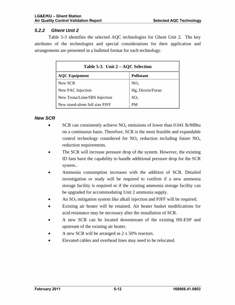
Table 5-3 identifies the selected AQC technologies for Ghent Unit 2. The key
attributes of the technologies and special considerations for their application and
arrangements are presented in a bulleted format for each technology.
Table 5-3. Unit 2 – AQC Selection
AQC Equipment Pollutant
New SCR NOx
New PAC Injection Hg, Dioxin/Furan
New Trona/Lime/SBS Injection SO3
New stand-alone full size PJFF PM
New SCR
SCR can consistently achieve NOx emissions of lower than 0.041 lb/MBtu
on a continuous basis. Therefore, SCR is the most feasible and expandable
control technology considered for NOx reduction including future NOx
reduction requirements.
The SCR will increase pressure drop of the system. However, the existing
ID fans have the capability to handle additional pressure drop for the SCR
system..
Ammonia consumption increases with the addition of SCR. Detailed
investigation or study will be required to confirm if a new ammonia
storage facility is required or if the existing ammonia storage facility can
be upgraded for accommodating Unit 2 ammonia supply.
An SO3 mitigation system like alkali injection and PJFF will be required.
Existing air heater will be retained. Air heater basket modifications for
acid resistance may be necessary after the installation of SCR.
A new SCR can be located downstream of the existing HS-ESP and
upstream of the existing air heater.
A new SCR will be arranged as 2 x 50% reactors.
Elevated cables and overhead lines may need to be relocated.

LG&E/KU – Ghent Station Air Quality Control Validation Report Selected AQC Technology
February 2011 5-13 168908.41.0803
New PAC Injection
A PJFF is recommended in conjunction with PAC injection.
PAC to be injected downstream of the ID fans but upstream of new PJFF.
PAC Injection can meet the new Hg compliance limit of 1 x 10⁻⁶ lb/MBtu
or lower on a continuous basis and new dioxin/furan compliance limit of
15 x 10-18 lb/MBtu or lower on a continuous basis and hence is the most
feasible control technology.
Dioxin and Furan removal will be a co-benefit with targeted mercury
emissions removal and additional PAC consumption beyond mercury
removal will be required.
The use of PAC system will slightly increase the truck traffic at the plant
due to increased bulk deliveries.
New PJFF
A PJFF can consistently achieve PM emissions of less than 0.03 lb/MBtu
on a continuous basis and has the capability to expand in order to meet PM
emissions lower than 0.03 lb/MBtu. Hence, a PJFF is the most feasible
and expandable control technology considered for PM reduction,
including future requirements.
PJFF offers more direct benefits or co-benefits of removing future multi-
pollutants like mercury and sulfuric acid using some form of injection
upstream.
The PJFF will increase pressure drop of the system. As such, the draft
system needs to be investigated and new booster fans will be required.
Additional auxiliary power requirement will need to be considered for new
booster fans.
A new ash handling system will be required to collect ash from PJFF
hoppers.
Additional maintenance will be required for replacing bags and cages.
The PJFF can be located downstream of the existing ID fans and upstream
of the new booster fans and can possibly be installed as suggested in the
high level layout drawings as shown in Appendix A.
The PJFF for Unit 2 will be located on the north side of the existing Unit 2
hot-side ESP and east side of the existing Unit 2 scrubber modules. The
PJFF will be elevated above the ground level. Above and under ground
utilities will be investigated, evaluated, and, if necessary, relocated.

LG&E/KU – Ghent Station Air Quality Control Validation Report Selected AQC Technology
February 2011 5-14 168908.41.0803
New SO3 Control System (Reagent Injection)
A reagent injection system that injects trona, Lime or SBS into the flue gas to
remove SO3 would be necessary.
A PJFF is recommended in conjunction with a reagent injection system.
Trona/lime/SBS would be injected downstream of the SCR but upstream
of the air heater.
Reagent injection can reduce the sulfuric acid emissions on a continuous
basis and mitigate the visible blue plume formation from the chimney
which is often associated when burning high sulfur coal.
The use of sorbent system will slightly increase the truck traffic at the
plant.
5.2.3 Ghent Units 3 and 4
Table 5-4 identifies the selected AQC technologies for Units 3 and 4. The key
attributes of the technologies and special considerations for their application and
arrangements are presented in a bulleted format for each technology.
Table 5-4. Units 3 and 4 – AQC Technology Selection
AQC Equipment Pollutant
New PAC Injection Hg, Dioxin/Furan
New stand-alone full size PJFF PM
New PAC Injection
A PJFF is recommended in conjunction with PAC injection.
PAC to be injected downstream of the existing air heater but upstream of
new PJFF.
PAC Injection can meet the new Hg compliance limit of 1 x 10⁻⁶ lb/MBtu
or lower on a continuous basis and new dioxin/furan compliance limit of
15 x 10-18 lb/MBtu or lower on a continuous basis and hence is the most
feasible control technology.
Dioxin and Furan removal will be a co-benefit with targeted mercury
emissions removal and additional PAC consumption beyond mercury
removal will be required.
The use of PAC system will slightly increase the truck traffic at the plant
due to increased bulk deliveries.
LG&E/KU – Ghent Station Air Quality Control Validation Report Selected AQC Technology
February 2011 5-15 168908.41.0803
New PJFF
A PJFF can consistently achieve PM emissions of less than 0.03 lb/MBtu
on a continuous basis and has the capability to expand in order to meet PM
emissions lower than 0.03 lb/MBtu. Hence, a PJFF is the most feasible
and expandable control technology considered for PM reduction,
including future requirements.
PJFF offers more direct benefits or co-benefits of removing future multi-
pollutants like mercury and sulfuric acid using some form of injection
upstream.
The PJFF will increase pressure drop of the system. As such, the draft
system needs to be investigated and new ID fans will be required. The
existing ID fans will be bypassed and abandoned in place. Additional
auxiliary power requirement will need to be considered for the new ID
fans
A new ash handling system will be required to collect ash from PJFF
hoppers.
Additional maintenance will be required for replacing bags and cages.
The PJFF can be
located downstream of the existing air heater and upstream of the new ID
fans and can possibly be installed as suggested in the high level layout
drawings as shown in Appendix A.
The PJFF for Unit 3 will be located on the east side of the Unit 3 boiler
and west side of Unit 2 boiler. The PJFF will be elevated above the ground
level. Existing structures which includes utility corridor walkway
enclosure, maintenance shop, personnel skywalk, etc. will be investigated,
evaluated, and, if necessary, relocated. Above and under ground utilities
will be investigated, evaluated, and, if necessary, relocated. If practical,
the utility walkway enclosure and personnel skywalk will be re-
established upon completion of the PJFF.
The PJFF for Unit 4 will be located on the north side of the Unit 4 WFGD
and stack. Existing warehouse structure and foundation will be
demolished. Above and under ground utilities will be investigated,
evaluated, and, if necessary, relocated.

LG&E/KU – Ghent Station Air Quality Control Validation Report Validation Analyses
February 2011 6-1 168908.41.0803
6.0 Validation Analyses
The following sections describe the analyses of various balance of plant systems necessary to validate the selected AQC equipment.
6.1 Draft System Analysis As a part of the draft system analysis of the AQC validation process for Ghent,
the flue gas draft fans need to be evaluated to determine if modifications, replacements,
or additions to the existing fans will be required. This is due to the installation of
additional draft system equipment to control certain flue gas emissions. For Units 1, 3,
and 4 the modifications and additions to the draft system being considered include new
PJFF systems that will supplement the existing ESPs of each unit in the removal of
particulate. For Unit 2 draft system modifications and additions being considered are a
new SCR system for removing NOx emissions and a new PJFF system. For more detail
on the AQC equipment modifications, additions, etc. for each Ghent unit refer to
Section 5.0.
For the sizing of any new fans for the Ghent site, the standard Black & Veatch fan
sizing philosophy for developing Test Block conditions as additional margin on MCR
conditions is recommended. This philosophy includes the application of the following
items to the required MCR conditions for new or modified fans:
10 percent margin on flue gas flow exiting the boiler
50 percent margin on leakages throughout the draft system
50 percent margin on air heater differential pressure
25oF temperature increase at the fan inlet
Adjustments of draft system pressure drops to correspond with increased
Test Block flow rates
1.0 inch of water (inw) control allowance
The application of these items typically results in flow margins in the range of 20
to 30 percent and pressure margins in the range of 35 to 45 percent. If the flow and/or
pressure margins for the Test Block conditions fall outside of these ranges the items listed
above are typically adjusted appropriately.
Additionally, following the preliminary analyses of the Ghent draft systems, there
will be a discussion on draft system stiffening, or transient design pressure, requirements
per NFPA 85.

LG&E/KU – Ghent Station Air Quality Control Validation Report Validation Analyses
February 2011 6-2 168908.41.0803
6.1.1 Unit 1
Based on the additions to the Unit 1 draft system previously discussed and the
flue gas flow through the draft system would change as follows. At the outlet of the
existing ID fans the flue gas would travel to the new PJFF system allowing for the
removal of finer particulate emissions before entering two new 50 percent capacity
booster fans. The new booster fans, assumed to be equipped with variable speed control,
would then send the flue gas to the WFGD system. An illustration of the Unit 1 future
draft system based on these changes is shown in Figure 6-1.
With the expected installation of a PJFF system, the pressure demand on the draft
fan system will be significantly higher than what the existing ID fans may deliver while
still providing adequate margin. However, the efficient variable speed capabilities and
recent major modifications are advantageous to operation and longevity of the existing ID
fans. Therefore, it would be desirable to supplement the capabilities of the existing Unit
1 ID fans as opposed to replacing them. B&V proposes this be accomplished with two
new 50 percent capacity centrifugal booster fans, also with variable speed control.
Figure 6-1. Unit 1 Future Draft System

LG&E/KU – Ghent Station Air Quality Control Validation Report Validation Analyses
February 2011 6-3 168908.41.0803
Future Draft System Characteristics
The major performance characteristics of the Unit 1 future draft system at MCR
are as follows in Table 6-1. Note that the items in bold in Table 6-1 are new.
Table 6-1. Unit 1 Future Draft System Characteristics at MCR
SCR system leakage 2% (estimated)
Air heater leakage 10% (estimated)
ESP leakage 5% (estimated)
PJFF system leakage 3%
Flue gas temperatures
Boiler outlet 729° F
SCR outlet 729° F
Air heater outlet 361° F
ESP outlet 358° F
PJFF outlet 358° F
ID fan outlet ~375° F (calculated)
Booster fan outlet ~375° F (calculated)
WFGD outlet ~130° F (calculated)
Furnace pressure -0.5 inwg
Draft system differential pressures
Boiler 2.7 inw
SCR 10.0 inw
Air heater 9.2 inw
ESP 3.3 inw
PJFF 8.0 inw
WFGD 4.4 inw
Stack 1.7 inw

LG&E/KU – Ghent Station Air Quality Control Validation Report Validation Analyses
February 2011 6-4 168908.41.0803
Based on the layout of the future draft system in Figure 6-1 and the future draft
system characteristics in Table 6-1, the estimated performance requirements of the new
booster fans at MCR are shown in Table 6-2. Also in Table 6-2 are the recommended
Test Block conditions developed using the Black & Veatch fan sizing philosophy
previously outlined in this section. Note the flow and pressure margins of 25 and 39
percent, respectively. To keep the booster fan Test Block pressure margin within the
typical range of 35 to 45 percent the 1.0 inw control allowance was removed.
Table 6-2. Unit 1 New Booster Fan MCR and Recommended Test Block Conditions
MCR Test Block
Fan Speed (rpm), maximum ------ 900
Inlet Temperature (°F) 374 399
Inlet Density (lb/ft3) 0.0461 0.0445
Flow per Fan (acfm) * 1,122,000 1,402,000
Inlet Pressure (inwg) -8.0 -10.8
Outlet Pressure (inwg) 6.1 8.8
Static Pressure Rise (inw) 14.1 19.6
Shaft Power Required (HP) ** 2,900 5,100
Efficiency (percent) ** 85 85
Number of Fans 2 2
Flow Margin (percent) --------- 25
Pressure Margin (percent) --------- 39
*Per fan basis with both fans in operation. **Estimated – assumes variable speed operation.
LG&E/KU – Ghent Station Air Quality Control Validation Report Validation Analyses
February 2011 6-5 168908.41.0803
6.1.2 Unit 2
Based on the additions to the Unit 2 draft system previously discussed the flue gas
would be redirected through the draft system as follows. At the outlet of the hot-side
ESP the flue gas would travel to the new SCR system allowing for the removal of NOx
emissions before entering the air heaters. Once the flue gas is through the air heaters it
would enter the existing ID fans. Between the existing ID fans and WFGD system would
be the new PJFF system and new booster fans. The new booster fans, assumed to be
equipped with variable speed control, would draw flue gas through the PJFF system and
send it to the WFGD system. Additionally, the SCR system is expected to require an
economizer bypass on the flue gas or water-side. An illustration of the Unit 2 future draft
system based on this description is shown in Figure 6-2.
With the expected installation of both an SCR system and a PJFF system, the
pressure demand on the draft fan system is expected to be significantly higher than what
the existing ID fans may deliver while still providing adequate margin. However, the
efficient variable speed capabilities and recent major modifications are advantageous to
operation and longevity of the existing ID fans. Therefore, it would be desirable to
supplement the capabilities of the existing Unit 2 ID fans as opposed to replacing them.
B&V proposes this be accomplished with two new 50 percent capacity centrifugal
booster fans as with Unit 1, also with variable speed control.
The economizer bypass for the SCR system is expected due to the relatively low
flue gas temperatures currently exiting the economizer which are not expected to change
significantly in the future. This is because a minimum SCR inlet temperature will need to
be maintained for the proper reactions to take place in the reactor and at lower loads.
When these temperatures decrease, additional energy may need to be injected into the
flue gas stream which can be accomplished by using the economizer bypass. However,
this economizer bypass may also be needed at full load as well due to the significant
temperature drop occurring through the hot-side ESPs. B&V will conduct further
analyses during conceptual design to determine the performance requirements of an
economizer bypass to control flue gas temperatures entering the SCR system.

LG&E/KU – Ghent Station Air Quality Control Validation Report Validation Analyses
February 2011 6-6 168908.41.0803
Figure 6-2. Unit 2 Future Draft System

LG&E/KU – Ghent Station Air Quality Control Validation Report Validation Analyses
February 2011 6-7 168908.41.0803
Future Draft System Characteristics
The major performance characteristics of the Unit 2 future draft system at MCR
are as follows in Table 6-3. Note that the items in bold in Table 6-3 are new.
Table 6-3. Unit 2 Future Draft System Characteristics at MCR
ESP leakage 5% (estimated)
SCR system leakage 2%
Air heater leakage 10% (estimated)
PJFF leakage 3%
Flue gas temperatures
Boiler outlet 610° F
ESP outlet 605° F
SCR outlet 605° F
Air heater outlet 309° F
PJFF outlet 309° F
ID fan outlet ~325° F (calculated)
Booster fan outlet ~325° F (calculated)
WFGD outlet ~125° F (calculated)
Furnace pressure -0.5 inwg
Draft system differential pressures
Boiler 4.6 inw
ESP 5.7 inw
SCR 10.0 inw
Air heater 7.8 inw
PJFF 8.0 inw
WFGD 9.9 inw
Stack 1.5 inw

LG&E/KU – Ghent Station Air Quality Control Validation Report Validation Analyses
February 2011 6-8 168908.41.0803
Based on the layout of the future draft system in Figure 6-2 and the future draft
system characteristics in Table 6-3, the estimated performance requirements of the new
ID fans at MCR are shown in Table 6-4. Also in Table 6-4 are the recommended Test
Block conditions developed using the Black & Veatch fan sizing philosophy previously
outlined in this section. Note the flow and pressure margins of 25 and 43 percent,
respectively. To keep the booster fan Test Block pressure margin within the typical
range of 35 to 45 percent the 1.0 inw control allowance was removed.
Table 6-4. Unit 2 New Booster Fan MCR and Recommended Test Block Conditions
MCR Test Block
Fan Speed (rpm), maximum ------ 900
Inlet Temperature (°F) 325 350
Inlet Density (lb/ft3) 0.0490 0.0471
Flow per Fan (acfm) * 1,088,000 1,364,000
Inlet Pressure (inwg) -8.0 -11.3
Outlet Pressure (inwg) 11.4 16.5
Static Pressure Rise (inw) 19.4 27.8
Shaft Power Required (HP) ** 4,000 7,100
Efficiency (percent)** 85 85
Number of Fans 2 2
Flow Margin (percent) --------- 25
Pressure Margin (percent) --------- 43
*Per fan basis with both fans in operation. **Estimated – assumes variable speed operation.

LG&E/KU – Ghent Station Air Quality Control Validation Report Validation Analyses
February 2011 6-9 168908.41.0803
6.1.3 Unit 3
Based on the additions to the Unit 3 draft system previously discussed, the flue
gas would be redirected through the draft system as follows. At the outlet of the existing
air heaters the flue gas would travel to the new PJFF system allowing for the removal of
finer particulate. The three new 33 percent centrifugal ID fans, assumed to be equipped
with variable speed control, would then draw the flue gas out of the PJFF system and
send it to the WFGD system. An illustration of the Unit 3 future draft system based on
this description is shown in Figure 6-3.
Due to operation and maintenance issues with the recently installed two 50
percent axial ID fans, the plant would like them to be replaced and bypassed with new
centrifugal type fans. However, due to the B&V recommended margins on flow and
pressure (Test Block conditions) above the MCR conditions with the addition of a PJFF
system, the new centrifugal ID fans will be required to be in a three fan arrangement. An
illustration of the Unit 3 future draft system based on this description is shown in
Figure 6-3.
Figure 6-3. Unit 3 Future Draft System

LG&E/KU – Ghent Station Air Quality Control Validation Report Validation Analyses
February 2011 6-10 168908.41.0803
Future Draft System Characteristics
The major performance characteristics of the Unit 3 future draft system at MCR
are as follows in Table 6-5. Note that the items in bold in Table 6-5 are new.
Table 6-5. Unit 3 Future Draft System Characteristics at MCR
SCR system leakage 2% (estimated)
Air heater leakage 10% (estimated)
ESP leakage 5% (estimated)
PJFF leakage 3%
Flue gas temperatures
Boiler outlet 731° F
ESP outlet 708° F
SCR outlet 708° F
Air heater outlet 322° F
PJFF outlet 322° F
ID fan outlet ~350° F (calculated)
WFGD outlet ~130° F (calculated)
Furnace pressure -0.5 inwg
Draft system differential pressures
Boiler 4.6 inw
ESP 5.8 inw
SCR 10.0 inw
Air heater 15.2 inw
PJFF 8.0 inw
WFGD 3.9 inw
Stack 2.0 inw
LG&E/KU – Ghent Station Air Quality Control Validation Report Validation Analyses
February 2011 6-11 168908.41.0803
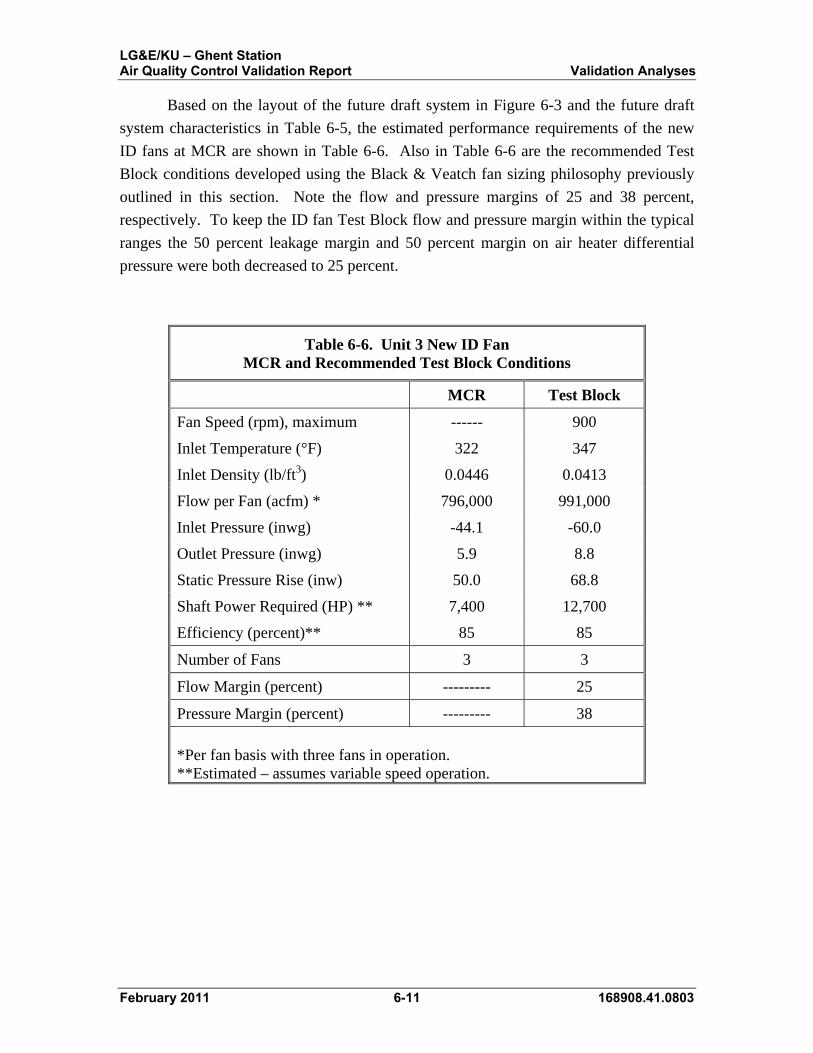
Based on the layout of the future draft system in Figure 6-3 and the future draft
system characteristics in Table 6-5, the estimated performance requirements of the new
ID fans at MCR are shown in Table 6-6. Also in Table 6-6 are the recommended Test
Block conditions developed using the Black & Veatch fan sizing philosophy previously
outlined in this section. Note the flow and pressure margins of 25 and 38 percent,
respectively. To keep the ID fan Test Block flow and pressure margin within the typical
ranges the 50 percent leakage margin and 50 percent margin on air heater differential
pressure were both decreased to 25 percent.
Table 6-6. Unit 3 New ID Fan MCR and Recommended Test Block Conditions
MCR Test Block
Fan Speed (rpm), maximum ------ 900
Inlet Temperature (°F) 322 347
Inlet Density (lb/ft3) 0.0446 0.0413
Flow per Fan (acfm) * 796,000 991,000
Inlet Pressure (inwg) -44.1 -60.0
Outlet Pressure (inwg) 5.9 8.8
Static Pressure Rise (inw) 50.0 68.8
Shaft Power Required (HP) ** 7,400 12,700
Efficiency (percent)** 85 85
Number of Fans 3 3
Flow Margin (percent) --------- 25
Pressure Margin (percent) --------- 38
*Per fan basis with three fans in operation. **Estimated – assumes variable speed operation.

LG&E/KU – Ghent Station Air Quality Control Validation Report Validation Analyses
February 2011 6-12 168908.41.0803
6.1.4 Unit 4
Based on the additions to the Unit 4 draft system previously discussed, the flue
gas would be redirected through the draft system as follows. At the outlet of the existing
air heaters the flue gas would travel to the new PJFF system allowing for the removal of
finer particulate. The three new 33 percent centrifugal ID fans, assumed to be equipped
with variable speed control, would then draw the flue gas out of the PJFF system and
send it to the WFGD system. An illustration of the Unit 4 future draft system based on
this description is shown in Figure 6-3.
Due to operation and maintenance issues with the recently installed two 50
percent axial ID fans, the plant would like them to be replaced and bypassed with new
centrifugal type fans. However, due to the B&V recommended margins on flow and
pressure (Test Block conditions) above the MCR conditions with the addition of a PJFF
system, the new centrifugal ID fans will be required to be in a three fan arrangement. An
illustration of the Unit 4 future draft system based on this description is shown in
Figure 6-4.
Figure 6-4. Unit 4 Future Draft System

LG&E/KU – Ghent Station Air Quality Control Validation Report Validation Analyses
February 2011 6-13 168908.41.0803
Future Draft System Characteristics
The major performance characteristics of the Unit 4 future draft system at MCR
are as follows in Table 6-7. Note that the items in bold in Table 6-7 are new.
Table 6-7. Unit 4 Future Draft System Characteristics at MCR
SCR system leakage 2% (estimated)
Air heater leakage 10% (estimated)
ESP leakage 5% (estimated)
PJFF leakage 3%
Flue gas temperatures
Boiler outlet 791° F
ESP outlet 770° F
SCR outlet 770° F
Air heater outlet 309° F
PJFF outlet 309° F
ID fan outlet ~340° F (calculated)
WFGD outlet ~125° F (calculated)
Furnace pressure -0.5 inwg
Draft system differential pressures
Boiler 4.0 inw
ESP 6.3 inw
SCR 10.0 inw
Air heater 8.6 inw
PJFF 8.0 inw
WFGD 13.0 inw
Stack 1.6 inw

LG&E/KU – Ghent Station Air Quality Control Validation Report Validation Analyses
February 2011 6-14 168908.41.0803
Based on the layout of the future draft system in Figure 6-4 and the future draft
system characteristics in Table 6-7, the estimated performance requirements of the new
ID fans at MCR are shown in Table 6-8. Also in Table 6-8 are the recommended Test
Block conditions developed using the Black & Veatch fan sizing philosophy previously
outlined in this section. Note the flow and pressure margins of 23 and 35 percent,
respectively. To keep the ID fan Test Block flow and pressure margin within the typical
ranges the 50 percent leakage margin and 50 percent margin on air heater differential
pressure were both decreased to 25 percent.
Table 6-8. Unit 4 New ID Fan MCR and Recommended Test Block Conditions
MCR Test Block
Fan Speed (rpm), maximum ------ 900
Inlet Temperature (°F) 309 334
Inlet Density (lb/ft3) 0.0462 0.0433
Flow per Fan (acfm) * 760,000 935,000
Inlet Pressure (inwg) -37.4 -49.6
Outlet Pressure (inwg) 14.6 20.4
Static Pressure Rise (inw) 52.0 70.0
Shaft Power Required (HP) ** 7,400 12,200
Efficiency (percent) ** 85 85
Number of Fans 3 3
Flow Margin (percent) --------- 23
Pressure Margin (percent) --------- 35
*Per fan basis with three fans in operation. **Estimated – assumes variable speed operation.

LG&E/KU – Ghent Station Air Quality Control Validation Report Validation Analyses
February 2011 6-15 168908.41.0803
6.1.5 Draft System Transient Design Pressures
The AQC equipment additions and changes to all of the Ghent units will likely be
considered major alterations or extensions to the existing facilities per the National Fire
Protection Association (NFPA) 85 code - Section 1.3 (2007 Edition). The code, in this
instance, would imply that the boiler and flue gas ductwork from the boiler outlet
(economizer outlet) to the ID fan inlet (it should be implied that this would include
booster fans) be designed for transient pressures of ± 35 inwg at a minimum per
Section 6.5. Further research is needed to determine whether the existing boilers and
draft systems of each of the Ghent units meets this criteria or if they will require
stiffening. Each new piece of AQC equipment, and its associated ductwork, being
considered for the Ghent units will also be required to meet this NFPA 85 requirement.
Additionally, in some sections of the future draft systems, the transient design pressures
will need to exceed the ± 35 inwg due to high negative draft pressures.
The Black & Veatch philosophy for calculating the minimum required transient
design pressures is based on the draft system being designed to 66 percent of its yield
stress for maximum continuous (fan Test Block) operating pressures and 95 percent for
short durations, or transient conditions. This results in a 44 percent increase in the
allowable stress throughout the draft system for short durations without resulting in
permanent deformation or buckling of any structural components. For example, if a
section of ductwork is expected to be exposed to negative draft pressures of -30 inwg
when the ID fans are operating at Test Block conditions, the calculated negative transient
design pressure would be 44 percent higher or -43.2 inwg. The positive transient design
pressure would still be +35 inwg. Since NFPA 85 requires that flue gas ductwork
between the boiler outlet and the ID fan inlet be designed for transient pressures of ± 35
inwg, calculated transient design pressures below ± 35 inwg are disregarded and the ± 35
inwg is used as the design transient pressure for that draft system component or section of
ductwork. For calculated transient design pressures over ± 35 inwg such as in the
previous example, the calculated pressure is used.
6.2 Auxiliary Electrical System Analysis The existing Ghent auxiliary power systems includes 25 kV switchyard
switchgear two bus system where 25 kV Bus A is fed from 138 kV–25 kV Reserve
Auxiliary Transformer (RAT) A, and 25 kV Bus B is fed from 138 kV–25 kV RAT B.
The 25 kV switchgear buses provide startup/backup power for each unit, and the unit
scrubber FGD auxiliary electrical systems with the exception of Unit 2 scrubber FGD
auxiliary electrical system. Unit 2 Scrubber FGD auxiliary electrical system 4KV buses
5A and 5B are fed from 25 kV–4.16 kV scrubber transformers SST FGD 5A and 5B.

LG&E/KU – Ghent Station Air Quality Control Validation Report Validation Analyses
February 2011 6-16 168908.41.0803
The 25 kV switchgear bus A supplies reserve power to Unit 1 scrubber 25 kV–4.16 kV
RAT 1C, Unit 1 and Unit 2 RAT1/2, and Plant Limestone Prep SST-LSA. The 25 kV
switchgear bus B supplies reserve power to Unit 3 and Unit 4 scrubber 25 kV–13.8 kV
RAT 3C and 4C, and 25 kV–4.16 kV RAT3/4, and Plant Limestone Prep SST-LSB. The
RATs and SST-LSs auxiliary transformers are connected in an “A” or “B” fashion to
each of the units’ 4.16 kV and 13.8 kV auxiliary electrical reserve incoming circuit
breakers for startup and backup power.
All units main plant auxiliary electrical system 4.16 kV switchgear buses UA and
UB are fed from their own respective two two-winding unit auxiliary transformer (UAT)
that is powered from their respective generator leads. Unit 1 4.16 kV switchgear
scrubber buses FGD1A and FGD1B are fed respectively from one three winding UAT1C
that is powered from Unit 1 generator leads. Unit 2 4.16 kV switchgear scrubber buses
FGD5A and FGD5B are fed respectively from two two-winding 25 kV–4.16 kV SSTFG-
5A and 5B respectively as described above. Unit 3 and Unit 4 13.8 kV switchgear
scrubber buses FGD3A and FGD3B, and FGD4A and FGD4B are fed respectively from
each of their respective two winding UAT3C/4C that is powered from their respective
Unit 3 and Unit 4 generator leads. Each 13.8 kV switchgear bus will feed a 13.8 kV–4.16
kV step down transformer that provides power to the Unit 3 and Unit 4 4.16 kV
switchgear buses.
The addition of PJFF on each unit and a SCR on Unit 2 will require the addition
of new ID Fans (Unit 3 and 4) or new booster fans (Units 1 and 2). All new fans will
have variable frequency drives (VFDs). The existing unit auxiliary transformers, reserve
auxiliary transformers, and 13.8 kV/4.16 kV switchgear buses were determined to have
insufficient spare capacity and short circuit ratings to power the PJFF and SCR additions,
which include new technology and fan electrical loads.
Each unit will require one new two winding AQC UAT that will be fed from their
respective generator leads. The secondary windings will power the new AQC 13.8 kV
and 4.16 kV switchgear buses for the fans and other various AQC loads. The
reserve/backup power for new AQC 13.8 kV and 4.16 kV switchgear buses will be fed
from new outdoor AQC 25 kV reserve switchgear and two new Unit 1 and Unit 2 AQC
25 kV–4.16 kV, and two new Unit 3 and Unit 4 AQC 25 kV–13.8 kV two winding RATs
fed from existing 25 kV switchgear described above. Unit 3 and Unit 4 AQC 13.8 kV
buses will each supply power to a two winding 13.8 kV–4.16 kV transformers which
supply power to the Unit 3 and Unit 4 AQC 4.16 kV switchgear buses. Further electrical
studies (short circuit, motor starting, etc.) will be performed during detailed design to
determine the final transformer impedance and MVA ratings. Also, further field

LG&E/KU – Ghent Station Air Quality Control Validation Report Validation Analyses
February 2011 6-17 168908.41.0803
investigation will be required to determine the best way to connect the new AQC 25 kV
switchgear into the existing 25 kV buses A and B.
The recommended location of the four new AQC RATs that will be connected to
the new 25 kV AQC switchgear will be in close proximity to the tie-in points on the
south side of the units. The recommended locations of each of the four new AQC UATs
will be in close proximity to each of their respective generator leads. Cable bus will be
routed during detailed design from the secondary windings of these auxiliary
transformers to the new AQC electrical buildings. The new electrical AQC buildings
would be located in the vicinity of the PJFF equipment as shown in the conceptual
sketches in Appendix A. The buildings will contain the new medium voltage (MV) and
low voltage (LV) switchgear, motor control centers (MCCs), and distributed control
system (DCS) cabinets. A DC and UPS system will also be included in the electrical
buildings to provide control power to the switchgear and DCS system. Motor control
centers and DCS I/O cabinets may be installed in a small electrical building adjacent to
remote AQC equipment to minimize cable lengths for the equipment in this area.
6.3 AQC Mass Balance Analysis Addition of PJFF will increase the amount of ash removed from the Ghent Units.
Ash Handling--Additional new ash handling system will be required for
new PJFF. Additional ash handling equipment may include but is not
limited to pipes, blowers, valves, etc. There will be approximately total of
10,760 lb/hr of additional waste (ash) generated for Ghent Station.
6.4 Reagent Impact Analysis Anhydrous Ammonia System--There will be an increase in the amount
of ammonia required if SCR systems are implemented on Unit 2.
Additional equipment required for anhydrous ammonia system may
include but is not limited to ammonia storage tank, ammonia feed pumps,
dilution air blowers, vaporizers, pipes, valves, instrumentation and control
equipments etc. There will be approximately total of 508 lb/hr of more
anhydrous ammonia required for Ghent Unit 2.
PAC Injection System--A new PAC injection system will be required for
mercury and dioxin/furan control. Additional equipment required for PAC
injection system may include but is not limited to PAC storage silo, PAC
injection lances, blowers, pipes, valves, instrumentation and control
equipments etc. There will be approximately total of 5,173 lb/hr of PAC
required for Ghent Station.

LG&E/KU – Ghent Station Air Quality Control Validation Report Validation Analyses
February 2011 6-18 168908.41.0803
Trona/Lime/SBS Injection System-- A new sorbent (trona/lime/SBS)
injection system will be required for SO3 control on Unit 2. Additional
equipment required for sorbent injection system may include but is not
limited to sorbent storage silo, injection lances, blowers, pipes, valves,
instrumentation and control equipments etc. There will be approximately
total of 6,329 lb/hr of sorbent (trona) required for Ghent Unit 2.
6.5 Chimney Analysis Based on the recommendations made in Section 5.2, analysis of the chimneys at
Ghent Station is not required. The Ghent Station units 1-4 will reuse the existing
chimneys.
6.6 Constructability Analysis Several major AQC construction projects have been executed at the Ghent plant
site over the last several years, with some projects still actively in construction as of the
date of this report. The construction facilities, utilities, and services established to
support these projects, such as parking, material laydown, fabrication areas, temporary
utilities, and support services are expected to be adequate to support the work scope
presented in this study. Some adjustment to construction facilities will be required to
support unit-specific project execution. These needs will be addressed in the detailed
construction execution plan submitted by the installing Contractor.
“Brown-field” construction of major new equipment on the existing Ghent plant
footprint will present significant challenges in construction due to congestion,
obstructions, and the need to keep existing units on line during construction. Each of the
four units present unique access and construction execution challenges to implementing
the selected AQC technologies. Accordingly, a high level constructability analysis was
completed as part of this study in order to identify and evaluate potential concerns with
the arrangement presented for each unit. A total of three conceptual plan sketches with
corresponding elevation sketches are attached to this study in Appendix A. Each sketch
depicts the current proposed arrangement, including refinements made per two site walk
down inspections and joint project team discussion. Following is a generalized
discussion of the sequence and concerns identified with the arrangement presented for
each unit.
Because of limited onsite construction facilities and laydown area, the difficulty
in outage scheduling, congested access, and the general confusion and complexity of
several simultaneous projects, it is assumed that the work described below will be done
sequentially by unit and not simultaneously. Due to the potential of new construction at
LG&E/KU – Ghent Station Air Quality Control Validation Report Validation Analyses
February 2011 6-19 168908.41.0803
Unit 1 impacting construction access to the east side of Unit 2, consideration should be
given to completing work at Unit 2 prior to start of work at Unit 1. Similarly, although of
less concern, completion of Unit 2 modifications prior to Unit 3 would allow better
access to Unit 2 from the courtyard area than after the addition of new structures required
for Unit 3.
6.6.1 Unit 1 Arrangement
The AQC technology proposed for Unit 1 consists of a two 50 percent PJFFs, two
50 percent VFDs booster fans, PAC and trona transfer equipment, and the associated
ductwork and ancillary equipment required to tie this equipment into the exhaust gas air
stream.
The major equipment is proposed to be located immediately south of the
southwest end of Unit 2 mechanical draft cooling tower, and west of the Unit 1 WFGD.
The PJFF equipment will be located above, and straddle, the existing Unit 1 WFGD inlet
duct. The new booster fans will be located below (west fan) or just south of (east fan) the
existing inlet duct and new PJFFs adjacent to the existing Unit 2 ID fans. This
arrangement minimizes obstruction to cooling tower inlet air flow, but places the PJFFs
above the outlet stacks of the cooling tower draft fans. This may create icing conditions
on the PJFFs during certain weather events. Crane access to the construction area is
limited. The main erection crane can be established on the northwest corner of the
proposed footprint; however, extensive temporary structural fill and crane matting will be
required to protect the half-buried cooling water piping running through this area.
Additional crane and construction access can be established along the north side of the
proposed footprint, in the cooling tower maintenance road.
Construction activities must be closely coordinated with plant operations to
ensure adequate access is maintained on the west end of the Unit 2 cooling tower to
conduct routine maintenance. The congested footprint has limited area to stage material.
Major components of ductwork and PJFFs must be modularized for efficient execution of
the work scope. It is assumed that the major component modules will be fabricated in
remote fabrication areas, transported to the work site via the north plant access road,
raised over the Unit 2 cooling tower and set in place by the main lift crane located on the
northwest end of the construction footprint.
The expected sequence of construction (and estimated timeframe) for installation
for the Unit 1 arrangement is as follows and as noted:
Install new flanges/blanking plates and transition duct pieces in the
existing WFGD inlet duct and at the ID fan (2 weeks, outage, this work
could also be completed at the time of the ductwork tie-in).

LG&E/KU – Ghent Station Air Quality Control Validation Report Validation Analyses
February 2011 6-20 168908.41.0803
Construct new foundations and any supporting structural steel
superstructure for the PJFF, ductwork and booster fans (5 months, non-
outage).
Install new PJFF, booster fans, ancillary systems such as PAC, trona and
ash handling, plus ductwork to tie-in points (16 months, non-outage).
Complete tie-in of ductwork to existing WFGD inlet duct and ID fans (2
weeks, outage).
Start-up and tune new PJFF, booster fans, PAC, trona, and ash handling
systems (10 weeks, combined outage and non-outage).
The main crane will have a limited boom swing due to its close proximity to the
Unit 2 chimney. Detailed rigging and lift plans must be developed for each major
component installed. The proposed arrangement requires the PJFF to be installed above
the existing WFGD inlet duct, requiring substantial work at heights and the resulting
complications and inefficiencies. Installation of foundations will be problematic due to
the existing congestion and the need to maintain unit operation to the extent practical.
Micropiles may be required for the booster fan foundations and the support steel
foundations on the south side of the inlet duct. In addition, the following issues will have
to be addressed in detail to support construction at Unit 1.
Above and below ground utility interferences and relocations may be
necessary, especially low overhead obstructions along the north access
road.
Ground and soil stability for setting cranes and heavy haul traffic must be
confirmed and special precautions taken in the area of the semi-exposed
Unit 2 cooling water piping.
The potential and magnitude of existing equipment relocations needed to
support access, crane setting, construction traffic flow, construction
operations activities, and placement of new AQC equipment and ancillary
equipment must be investigated.
Conflicts with existing plant operations must be evaluated and minimized.
Isolation of the work area from operating areas must be considered if
practical, while still allowing maintenance access to existing equipment.
Existing plant traffic along the north access road will be interrupted and
must be rerouted. Existing traffic patterns must be reestablished prior to
start of construction.
Demolition/modification of existing ductwork will require selective
dismantling operations in order to work around existing equipment and
ancillaries.

LG&E/KU – Ghent Station Air Quality Control Validation Report Validation Analyses
February 2011 6-21 168908.41.0803
Elevating the PJFF and ductwork above the existing equipment and
structures will require a substantial new foundation and superstructure.
New PAC and trona silos and associated transfer equipment must be
carefully located to maintain crane access to Unit 2 SCR and PJFF
construction activities. Combining the PAC and trona silos and associated
equipment for both Unit 1 and Unit 2 should be considered.
6.6.2 Unit 2 Arrangement
The AQC technology proposed for Unit 2 consists of a two 50% PJFFs, two 50%
VFD booster fans, two 50 percent SCR reactors, PAC and trona silos and transfer
equipment; and the associated ductwork and ancillary equipment required to tie this
equipment into the exhaust gas air stream.
The two SCR modules are proposed to be located close to their respective exhaust
gas trains in order to facilitate construction access and minimize new ductwork. The
conceptual arrangement places the east SCR module above an existing structural steel
frame supporting the Unit 1 SCR located immediately east of the Unit 2 east ESP. The
arrangement tentatively includes a new structural steel tower straddling the existing steel
frame, although ideally the existing framing might be incorporated into the support for
the Unit 2 SCR. The construction footprint can be accessed by construction equipment
via a narrow lane running north/south from the north access road, then along the east side
of Unit 2 chimney to the existing structural support frame. It is proposed that a lattice
boom crawler crane or large hydraulic truck crane can be located immediately northeast
of the support frame and used to erect the new steel support and then lift pre-fabricated
SCR and ductwork modules into place on the framing.
The west SCR module is conceptually placed on a new structural support frame
located on the southwest corner of Unit 2 west ESP, and below the Unit 3 and 4 coal
conveyor. It is proposed that a large lattice boom crawler crane be assembled in the
“courtyard” immediately southwest of the SCR footprint and used to lift pre-fabricated
support steel, SCR module, and ductwork modules into place. Construction materials can
be transported to the footprint via the north/south access alley running immediately east
of the existing Unit 2 absorbers, or from the south through existing roll up doors installed
in the enclosed ground level utility corridor. Components too large to pass through the
roll up doors can be lifted over the existing personnel skywalk, utility corridor and
maintenance shops using a second crane located to the south.
LG&E/KU – Ghent Station Air Quality Control Validation Report Validation Analyses
February 2011 6-22 168908.41.0803
The following issues will have to be addressed in detail to support construction of
the east and west SCR modules and ductwork at Unit 2.
The new steel structure supporting the east SCR module must be designed
to coexist with the existing structural frame. Additional investigation
regarding the actual incorporation of the existing support tower into the
support for the new SCR module must be completed at time of detail
design to ensure that the existing structure and its foundation can support
the loads imposed by the new construction.
Above and below ground utility interferences and relocations will be
necessary to install the foundations and structural framing for the west
SCR module. Additional investigation is recommended at both locations
to identify and locate any underground utilities that might be impacted.
Ground and soil stability for setting cranes and heavy haul traffic must be
confirmed, especially in the area of the Unit 2 cooling water lines east of
Unit 2.
The potential and magnitude of existing equipment and facility relocations
needed to support crane setting, construction traffic flow, construction
operations activities, and placement of new AQC equipment and ancillary
equipment must be investigated. This will be of particular importance in
the area of the west SCR support tower due to existing congestion. A
series of existing overhead power lines west of Unit 2 will likely require
relocation, along with the demolition of several abandoned foundations in
the area.
The design of the support tower for the west SCR module must take into
account existing equipment and structures that likely cannot be relocated.
A support bent for the overhead coal conveyor, an existing elevated cable
tray, and the Service Water Pump House are all located in the immediate
area proposed for the west tower and the final arrangement and design
must accommodate these obstructions.
The west SCR is tentatively located directly beneath existing Coal
Conveyor 3J, significantly complicating crane operation in the area.
Although prefabrication of SCR support framing, modules, and ductwork
sections should be used to the extent it is practical, size and weight of
lifted components will be limited to that which can be maneuvered around
the conveyor. Some temporary shoring or framing may be required to
“land” prefabricated sections where they can be slid into place under the
conveyor.

LG&E/KU – Ghent Station Air Quality Control Validation Report Validation Analyses
February 2011 6-23 168908.41.0803
Conflicts with existing plant operations must be evaluated and minimized.
Isolation of the work area from operating areas must be considered if
practical, while still allowing maintenance access to existing equipment.
Special consideration must be given to protecting the Unit 3 coal conveyor
from damage during SCR erection.
Plant traffic along the north access road and in the “courtyard” area will be
interrupted by construction and must be rerouted. Essential plant
operations traffic patterns must be defined and re-established prior to
starting the project.
Demolition/modification of existing ESP ductwork will require selective
dismantling operations to be scheduled into plant outages in order to work
around existing equipment and ancillaries.
The support structures for both SCR modules and their ductwork will
require substantial new foundations and superstructures installed in very
congested areas. Micropiles may be required for the foundations.
The two PJFFs, two booster fans, PAC and trona silos and transfer equipment,
and associated ductwork are proposed to be located immediately north of the existing
Unit 2 ESPs. The footprint for the new equipment must be reclaimed by eliminating
existing ductwork in this area. This will require installation of a bypass duct connecting
the common duct ending at the north end of the ESPs and the existing duct leading to the
inlets of the absorbers. The bypass will allow the remaining common duct to the north to
be demolished and the area prepared for foundation and support steel framing erection.
The dimensions of the proposed PJFF extend across the existing north access road. The
PJFF, associated structural support frame, and ductwork must be elevated in order to
allow the road to pass beneath the new construction. In addition, elevating the new
equipment allows new electrical auxiliaries and ash handling equipment to be located
beneath the elevated structure, concentrating equipment in the area it is needed and
reducing the overall “sprawl” of the new construction.
The congested construction footprint contains limited area in which to stage
material. Major components such as ductwork, booster fans, and PJFFs must be
modularized for efficient execution of the work scope. It is assumed that the major
component modules will be fabricated/dressed out in remote fabrication areas,
transported to the work site via the north plant access road, and set in place by the main
lift crane, which would be located in the access road on the east or west sides of the
construction footprint. It should be noted that the cranes established on the west side of
the PJFF construction will likely be hydraulic, truck mount units. The PJFF support steel
spanning the roadway to the east and the low overhead obstructions spanning the

LG&E/KU – Ghent Station Air Quality Control Validation Report Validation Analyses
February 2011 6-24 168908.41.0803
roadway to the west will not allow a lattice boom crawler crane to walk into place along
the west side of the new construction. These obstructions will also make it difficult to lay
a lattice work crane boom down along the roadway in severe weather
The following issues will have to be addressed in detail to support construction of
the PJFFs, booster fans, and ductwork at Unit 2.
Above and below ground utility interferences must be identified and
relocated in order to install the foundations and structural framing for the
PJFF support frame.
Ground and soil stability for setting cranes and heavy haul traffic must be
confirmed.
The elevated structure supporting the PJFFs will require careful
coordination with the existing road and the elevated piperack immediately
to the north of the road. The piperack serves all four units; it cannot be
taken out of service and must be accommodated in the structure’s design.
The foundations beneath the northernmost supports of the structure must
also take into account the steeply sloping riverbank immediately to the
north of the piperack.
The magnitude of existing equipment and facility relocations needed to
support crane setting, construction traffic flow, construction execution,
and placement of new AQC equipment and ancillary equipment must be
investigated, quantified and resolved. Special consideration must be given
to relocation of overhead electrical lines for the existing scrubbers and
modification of exhaust gas ductwork during outages.
Conflicts with existing plant operations must be evaluated and minimized.
Isolation of the work area from operating areas must be considered if
practical, while still allowing maintenance access to existing equipment.
Special consideration must be given to protecting the piperack north of the
main access road.
Plant traffic along the north access road will be interrupted by construction
and must be rerouted. Essential plant operations traffic patterns must be
defined and re-established prior to starting the project.
Demolition/modification of existing ESP ductwork will require selective
dismantling operations to be scheduled into plant outages in order to work
around existing equipment and ancillaries.

LG&E/KU – Ghent Station Air Quality Control Validation Report Validation Analyses
February 2011 6-25 168908.41.0803
The expected sequence of construction (and estimated timeframe) for installation
for the total Unit 2 arrangement is as follows and as noted:
Install foundations and structural steel support frame for by-pass ductwork
at PJFF (2 months, non-outage).
Install new flanges/blanking plates on existing ductwork as necessary to
install by-pass damper and install by-pass ductwork at PJFF (6 weeks,
outage).
Demo by-passed ductwork and associated support steel at PJFF (3 months,
non-outage).
Install foundations and superstructure for PJFF and ductwork support
frame and booster fans (5 months, non-outage).
Install PJFF, ductwork up to tie-in points, PAC/trona equipment, ash
handling, and booster fans (16 months, non-outage)
Install ductwork to tie PJFF into existing ductwork (2 weeks, outage)
Start-up and tune new PJFF, booster fans, PAC, trona, and ash handling
systems (10 weeks, combined outage and non-outage).
Install foundations and structural steel framing supporting east side SCR
reactor (4 months, non-outage)
Install new flanges/blanking plates on existing ductwork as necessary to
install east SCR inlet and outlet ductwork (4 weeks, outage).
Erect east side SCR and ductwork up to tie-in points (18 months, non-
outage).
Tie-in east side SCR ductwork into existing duct and install blanking
plates to re-direct flow through SCR (6 weeks, outage).
Relocate overhead electrical lines and underground piping and ductbanks
necessary to install foundations for west side SCR reactor. (6 weeks,
outage, could be partially concurrent with outage for the east side SCR)
Install foundations for west side SCR reactor structural steel support frame
(4 months, non-outage, could be concurrent with east side SCR)
Install new flanges/blanking plates on existing ductwork as necessary to
install west SCR inlet and outlet ductwork (4 weeks, outage, could be
concurrent with east side SCR).
Install foundations and structural steel framing supporting for west side
SCR reactor and ductwork (4 months, non-outage, could be concurrent
with east side SCR).
LG&E/KU – Ghent Station Air Quality Control Validation Report Validation Analyses
February 2011 6-26 168908.41.0803
Erect west side SCR and ductwork up to tie-in points (18 months, non-
outage, could be concurrent with east side SCR).
Tie-in west side SCR ductwork into existing duct and install blanking
plates to re-direct flow through SCR (6 weeks, outage, could be
concurrent with east side SCR).
Start-up and tune both east and west side SCRs (10 weeks, combined
outage and non-outage).
6.6.3 Unit 3 Arrangement
The AQC technology proposed for Unit 3 consists of a single 100% PJFF, three
50% VFD ID fans, PAC and trona transfer equipment, and the associated ductwork and
ancillary equipment required to tie this equipment into the exhaust gas air stream.
The major equipment is proposed to be located in the courtyard area south of the
Unit 3 ID fans and east of the Unit 3 powerblock. The PJFF equipment will be elevated
to allow ground-level access to existing silos and equipment east of Unit 3. The elevated
PJFF will straddle the utility corridor currently located in the walkway enclosure between
Units 2 and 3. New ductwork will connect the exhaust ductwork upstream of the existing
ID fans to the PJFF inlet. New ID fans will be located at ground level between the PJFF
outlet and existing Coal Transfer House 5 and adjacent waste sump. New ductwork
downstream of the ID fans will connect to existing ductwork upstream of the Unit 3
scrubber inlet, bypassing the existing ID fans. The existing machine shop will require
relocation to accommodate the PJFF and the skywalk will be temporarily removed during
construction and then reincorporated into the new superstructures when complete.
The expected sequence of construction (and estimated timeframe) for installation
for the Unit 3 construction is as follows:
Demo and/or relocate existing structures in the way of new construction,
i.e.; utility corridor walkway enclosure, maintenance shop, personnel
skywalk, etc. (3 months, non-outage).
Install new flanges/blanking plates and transition duct pieces in the
existing inlet and outlet ductwork adjacent to the existing Unit 3 ID fans
(2 weeks, outage, this work could also be completed at the time of the
ductwork tie-in).
Construct new foundations and any supporting structural steel
superstructure for the PJFF, ductwork and booster fans. (4 months, non-
outage).
Install new PJFF, booster fans, ancillary systems such as PAC, trona and
ash handling, plus ductwork to tie-in points. (16 months, non-outage).

LG&E/KU – Ghent Station Air Quality Control Validation Report Validation Analyses
February 2011 6-27 168908.41.0803
Complete tie-in of ductwork to existing scrubber inlet duct and ID fans (3
weeks, outage).
Start-up new PJFF, booster fans, PAC, trona, and ash handling systems
(10 weeks, combined outage and non-outage).
Reinstall modified utility corridor walkway enclosure and elevated
skywalk (2 months, non-outage).
The main crane will be located in the “courtyard” area, in close proximity to operating plant systems. Limited amounts of construction material can be staged in the courtyard, making modularization of major ductwork and PJFFs components a necessity. Major component modules will be fabricated in remote fabrication areas, transported to the work site via the south plant access road, raised over the ground level pipe corridor by a second crane, and set in place by the main lift crane located in the courtyard. Detailed rigging and lift plans must be developed for each major component installed. The proposed arrangement requires the PJFF to be installed above the existing utility corridor between Unit 2 and Unit 3, and below the Unit 3 coal conveyor. This configuration will require substantial work at heights and the resulting complications and inefficiencies. Installation of foundations will be problematic due to the existing congestion of underground utilities and existing pipe trench, and the need to maintain unit operation to the extent practical. Micropiles may be required for the ID fan foundations and the ductwork support steel foundations located adjacent to existing Unit 3 building structure. In addition, the following issues will have to be addressed in detail to support construction at Unit 3.
The new steel structure supporting the PJFF must be designed to maintain vehicle access to the east side of Unit 3, avoid disrupting the utility corridor in the ground level walkway, and avoid impact to the existing tanks to the south.
Above and below ground utility interferences and relocations may be necessary, especially in the “courtyard” area. Particular care will be required to minimize impact on the existing pipe trench and the coal transfer house foundation.
Ground and soil stability for setting cranes and heavy haul traffic must be confirmed.
The potential and magnitude of existing equipment relocations needed to
support access, crane setting, construction traffic flow, construction
operations activities, and placement of new AQC equipment and ancillary
equipment must be investigated. A series of existing overhead power lines
across the north side of the courtyard will likely require relocation.
LG&E/KU – Ghent Station Air Quality Control Validation Report Validation Analyses
February 2011 6-28 168908.41.0803
Conflicts with existing plant operations must be evaluated and minimized.
Isolation of the work area from operating areas must be considered if
practical, while still allowing maintenance access to existing equipment.
Special consideration must be given to incorporating the re-established
ground level walkway and elevated skyway between Units 2 and 3 after
completion of PJFF erection.
Existing plant traffic along the utility corridor, maintenance skywalk, and
“courtyard” area will be interrupted and must be rerouted. Existing traffic
patterns must be reestablished prior to start of construction.
Demolition/modification of existing ductwork will require selective
dismantling operations in order to work around existing equipment and
ancillaries.
Elevating the PJFF and ductwork above the existing equipment and
structures will require a substantial new foundation and superstructure.
6.6.4 Unit 4 Arrangement
The AQC technology proposed for Unit 4 consists of a single 100% PJFF, three
50% VFD ID fans, PAC and trona transfer equipment, and the associated ductwork and
ancillary equipment required to tie this equipment into the exhaust gas air stream.
The major equipment is proposed to be located in the area west of the Unit 4 ESP
area currently occupied by a warehouse. The PJFF equipment will be constructed on a
ground-level foundation with inlet and outlet both on the east end of the PJFF. New
common ductwork will connect the two exhaust ductwork trains immediately north of the
Unit 4 powerblock and forward it to the PJFF. Three new ID fans will be located at
ground level at the PJFF outlet and common ductwork will forward the treated exhaust to
a tie-in point upstream of the existing WFGD. The existing ID fans will be bypassed.
The expected sequence of construction (and estimated timeframe) for installation
for the Unit 4 arrangement is as follows and as noted:
Demolish existing warehouse structure and foundation (6 weeks, non-
outage)
Install new flanges/blanking plates and transition duct pieces in the
existing Unit 4 outlet duct and the inlet duct to the scrubber (3 weeks,
outage, this work could also be completed at the time of the ductwork tie-
in).
Construct new foundations and any supporting structural steel
superstructure for the PJFF, ductwork and ID fans (3 months, non-outage).

LG&E/KU – Ghent Station Air Quality Control Validation Report Validation Analyses
February 2011 6-29 168908.41.0803
Install new PJFF, ID fans, ancillary systems such as PAC, trona and ash
handling, plus ductwork to tie-in points (16 months, non-outage).
Complete tie-in of ductwork to existing scrubber inlet duct and duct
upstream of the existing ID fans (6 weeks, outage).
Start-up new PJFF, booster fans, PAC, trona, and ash handling systems
(10 weeks, combined outage and non-outage).
Crane access for construction of Unit 4 appears relatively good, although access
may be limited to a great extent to the north side due to the shallow embedment of large
bore circulating water piping on the south side of the construction footprint. Extensive
coordination of existing ductwork modification and the installation of new ductwork on
downstream of Unit 4 and around the existing ID fans will be required to minimize
outage schedule. In addition, the following issues will have to be addressed in detail to
support construction at Unit 4.
Above and below ground utility interferences and relocations may be
necessary, especially on the south side of the PJFF construction footprint
in the area of the circ water pipe corridor. Ductwork supports in the pipe
corridor area may be required to “bridge” the corridor to avoid
excavations within the corridor.
Ground and soil stability for setting cranes and heavy haul traffic must be
confirmed, especially in the pipe corridor area.
The potential and magnitude of existing equipment relocations needed to
support access, crane setting, construction traffic flow, construction
operations activities, and placement of new AQC equipment and ancillary
equipment must be investigated.
Conflicts with existing plant operations must be evaluated and minimized.
Isolation of the work area from operating areas must be considered if
practical, while still allowing maintenance access to existing equipment.
Existing plant traffic along the west end of the north access road will be
interrupted and must be rerouted. Existing traffic patterns must be
reestablished prior to start of construction.
Demolition/modification of existing WFGD inlet and ID fan ductwork
will require selective dismantling operations in order to work around
existing equipment and ancillaries.
Design and installation of ductwork support foundations in the area of the
existing ID fans will require careful coordination due to the congestion in
the area. Micropiles may be required for those foundations.

LG&E/KU – Ghent Station Air Quality Control Validation Report Validation Analyses
February 2011 6-30 168908.41.0803
6.7 Truck/Rail Traffic Analysis The modifications proposed for the four Ghent units will result in additional bulk
material required to support the AQC processes. These materials will be delivered from
offsite on a regular basis and stored onsite for use. Preliminary estimates of the rate of
use of sorbents or reagents required in the proposed AQC processes by unit are listed in
Table 6-9. Additional delivery traffic for the site as a whole will be addressed
accordingly.
Table 6-9. Sorbents and Reagents Consumption Rates (tph)
Material Unit 1 Unit 2 Unit 3 Unit 4 Station Total
PAC 0.636 0.621 0.681 0.649 2.59
Sorbent (trona) Note 1 3.16 Note 1 Note 1 3.16 addn’l
Anhydrous ammonia Note 2 0.254 Note 2 Note 2 0.254 addn’l
tph - tons per hour. Notes: 1. Current rate of consumption of trona at Units 1, 3 and 4 will remain essentially
unchanged. 2. Current rate of consumption of anhydrous ammonia at Units 1, 3 and 4 will remain
essentially unchanged.
Although a rail spur exists and passes by the Ghent Station, it is not currently used
for any materials deliveries. Due to the distance between the existing trackage and the
units, using the existing rail system for periodic delivery of other bulk materials would be
problematic. Accordingly, delivery of bulk sorbents and reagents for the proposed AQC
systems will be assumed to be via truck on existing roads.
Dry bulk material, such as PAC and sorbent (trona), is normally delivered in
fully-enclosed bulk delivery trucks and offloaded using a pneumatic transfer system
integral to the truck. A standard over-the-road trailer truck size for these materials is
nominally 20 tons per load. Anhydrous ammonia is usually transported in a pressurized
tank truck with a nominal capacity of 10,000 gallons. Based on the consumption rates in
the Table 6-9 above and the nominal truck sizes, the additional truck deliveries to the
Ghent site can be summarized as follows.
PAC 22 loads per week
Sorbent (trona) 27 loads per week additional
Anhydrous ammonia 1.7 loads per week additional

LG&E/KU – Ghent Station Air Quality Control Validation Report Validation Analyses
February 2011 6-31 168908.41.0803
Therefore, the total additional truck deliveries estimated to provide sorbents or
reagents is approximately 50 loads per week. Assuming delivery operations are limited
to five days a week and an 8-hour day, the maximum additional truck deliveries to site
would be approximately 10 per day or 1 every 48 minutes over and above the current
deliveries being made. Existing roads onsite should be able to accommodate the
additional deliveries. A tank or silo is often provided for each material at each unit to
minimize the size and length of distribution systems. However, where practical,
consideration should be given to consolidated tanks or silos located so as to serve more
than one unit, in order to minimize unloading time and extended truck travel onsite. The
arrangements as proposed combine the silos for Units 1 and 2 to minimize the new
construction as well as decrease congestion.
The PJFF system added at each unit will capture additional particulate that will
need to be landfilled. The total expected additional fly ash removed from the exhaust
streams of the four units is estimated at 10,760 lb/hr, or approximately 129 tons per day
of operation of all four units. This increased volume will require additional operating
time for the existing (and augmented) ash transfer systems to deliver the ash to the ash
handling area. Current ash disposal activities will have to increase accordingly.
The modifications proposed include no changes to the existing FGD scrubbers at
any of the four units. Therefore limestone consumption and gypsum or scrubber
byproduct production are not expected to change appreciably. No modifications to the
existing limestone or scrubber byproduct bulk materials handling systems are expected to
be required.

LG&E/KU – Ghent Station Air Quality Control Validation Report Conclusion
February 2011 7-1 168908.41.0803
7.0 Conclusion
This Air Quality Control Validation Report confirms the feasibility of installing
certain AQC equipment at Ghent Station and presents the supporting considerations,
arrangements, and preliminary validation analyses for the AQC equipment that will be built
upon in the next steps of the project to complete the conceptual design and budgetary cost
estimate.
After review of the presented information and further discussions, LG&E/KU has
directed B&V to proceed to the conceptual design and budgetary cost estimate steps based
on the following arrangements and summarized in Table 7-1.
Unit 1 shall include the existing SCR, existing sorbent injection system, existing CS-
ESP, existing ID fans, new PAC injection system, new PJFF, new booster fans, existing
WFGD, and existing chimney. A neural network shall also be included. Ghent Unit 1
Arrangement with the new split box PJFF (2 x 50%) located above the existing WFGD
Supply ductwork is to be utilized.
Unit 2 shall include a new SCR, new sorbent injection system, existing ID fans, new
PAC injection system, new PJFF, new booster fans, existing WFGD, and existing chimney.
A neural network shall also be included. The Ghent Unit 2 Arrangement described below
shall be utilized. One side of the new split SCR reactor (2 x 50%) shall be located to the
east of the Unit 2 east HS-ESP above the current Unit 1 structural steel SCR support
structure. The other side of the split SCR reactor shall be located near the southwest corner
of the Unit 2 west HS-ESP above the electrical cable tray and below the existing Unit 3 and
4 coal conveyor. The PJFF shall be located at the north end of the existing HS-ESP and will
extend above and over the main plant access road. Cost associated with installation of the
SCR shall be easily identifiable and separated for further consideration based on final
regulations.
Unit 3 shall include the existing HS-ESP, existing SCR, existing sorbent injection
system, new PAC injection system, new PJFF, new ID fans, existing WFGD, and existing
chimney. A neural network shall also be included. Ghent Unit 3 Arrangement Flow
Biasing Option 1 with the new split box PJFF and four ID Fans located in the courtyard area
is to be utilized. For the complete Flow Biasing Report refer to Appendix B.
Unit 4 shall include the existing HS-ESP, existing SCR, existing sorbent injection
system, new PAC injection system, new PJFF, new ID fans, existing WFGD, and existing
chimney. A neural network shall also be included. Ghent Unit 4 Arrangement Flow
Biasing Option 1 with the new split box PJFF and four ID Fans located in the west of the
unit and north of the WFGD is to be utilized.

LG&E/KU – Ghent Station Air Quality Control Validation Report Conclusion
Table 7-1. AQC Technologies
Unit 1 Unit 2 Unit 3 Unit 4
NOx Control Existing SCR New SCR Existing SCR Existing SCR
SO2 Control Existing WFGD Existing WFGD Existing WFGD Existing WFGD
PM Control New PJFF New PJFF New PJFF New PJFF
HCl Control Existing WFGD and Existing Sorbent Injection
Existing WFGD and New Sorbent Injection
Existing WFGD and Existing Sorbent Injection
Existing WFGD and Existing Sorbent Injection
CO Control New NN New NN New NN New NN
SO3 Control Existing Sorbent Injection
New Sorbent Injection
Existing Sorbent Injection
Existing Sorbent Injection
Hg Control New PAC Injection New PAC Injection New PAC Injection New PAC Injection
Dioxin/Furan Control
New PAC Injection New PAC Injection New PAC Injection New PAC Injection
Fly Ash Sales Existing CS-ESP Existing HS-ESP Existing HS-ESP Existing HS-ESP
In addition, the following items shall also be considered in the next step of the
project.
Consideration of high air heater exit gas temperatures on all units
may require higher temperature PJFF bags.
Include fire protection requirements for PJFF as directed by
LG&E/KU.
Coordinate and consider how the on-going ash handling system
modifications being completed under separate study by LG&E/KU
and B&V may be affected by the potential installation of the PJFFs
at all four units.
Include demolition costs in the cost estimates for any existing
equipment bypassed or abandoned as separate line items in the cost
estimates.
For Unit 2, relocate sorbent injection point to downstream of the air
heater.
An economizer bypass system should be included as required to
provide Unit 2 turndown capability with respect to SCR operation
and inlet temperature control.
For Units 3 and 4, consider Option 1 from Flow Biasing Options
report for balancing or biasing flows as can be done under current
February 2011 7-2 168908.41.0803

LG&E/KU – Ghent Station Air Quality Control Validation Report Conclusion
February 2011 7-3 168908.41.0803
operation. Refer to Appendix A for the conceptual sketches of the
three options and refer to Appendix B for the report.
Include siding over all exposed areas and equipment near the Unit 2
cooling tower.
Investigate if there are any Unit 2 cooling tower performance
concerns with the proposed arrangement of the Unit 1 PJFF.
If Unit 2 SCR is installed first and the unit will be required to run in
this configuration, a new ID Fan power supply transformer will be
required.
Separate redundant silos for PAC shall be included for each unit.
New redundant sorbent silos to be included for Unit 2.
Review and modify the Unit 2 west low dust SCR arrangement with
consideration for a larger high dust SCR arrangement based on
physical space constraints due to the existing Unit 3 and 4 coal
conveyor.
Consider adding a permanent tank for chemical cleaning if too much
of the courtyard area gets consumed with Unit 3 equipment.
To the greatest extent possible, the same type of bags and cages for
use in the PJFFs should be used across the entire LG&E/KU fleet to
minimize spare part requirements. Additional warehousing should
be included to store a minimum of one entire set of bags and cages.
Include higher flue gas temperatures provided by LG&E/KU in the
draft system analysis for all units.

LG&E/KU – Ghent Station Air Quality Control Validation Report Appendix A
February 2011 A-1 168908.41.0803
Appendix A Conceptual Sketches

LG&E/KU – Ghent Station Air Quality Control Validation Report Appendix A
February 2011 A-2 168908.41.0803
Unit 1 Arrangements

200 40 80 120 160
20
0
40
80
120
APPROX SCALE - FT
N
72'
50% PJFF
88'
72'
50% PJFF
88' NEW WEST BOOSTER FAN (BELOW)
TIE NEW DUCT TO EXISTING DUCT
1
3 2
UNIT 1 CONCEPTUAL ARRANGEMENT SKETCH
2 - 50% PJFFS AND 2 - 50% BOOSTER FANS
PJFF INLET DUCTWORK 16' SQ ASSUMED
PJFF OUTLET DUCTWORK 16' SQ ASSUMED
COMMON ASH HANDLING EQPMTAREA (BELOW)
COMMON ELECT EQPMT AREA (BELOW)
COMMON FAN VFD ENCLOSURE
PAC FOR UNIT 1 SUPPLIED FROM COMMON SILO & TRANSFER EQPMT AT UNIT 2
NEW EAST BOOSTER FAN
EXISTING COOLING TOWER ELECTRICAL BLDG (BELOW)

~+67'
+0'
SECTION 1 SECTION 2 SECTION 3EAST PJFF SIMILAR EAST PJFF SIMILAR AND AS NOTED EAST PJFF SIMILAR
NOT TO SCALE NOT TO SCALE NOT TO SCALE
EXISTING DUCT
50% PJFF
EXISTING DUCT
50% PJFF 50% PJFF
EXISTING ID FAN
NEW BOOSTER FAN
EXISTING ID FAN
NEW BOOSTER FAN (BEHIND ID FAN)
BOOSTER FAN LOCATION AT EAST PJFF
UNIT 1 CONCEPTUAL ARRANGEMENT SKETCH
SECTIONS
LG&E/KU – Ghent Station Air Quality Control Validation Report Appendix A
February 2011 A-3 168908.41.0803
Unit 2 Arrangements
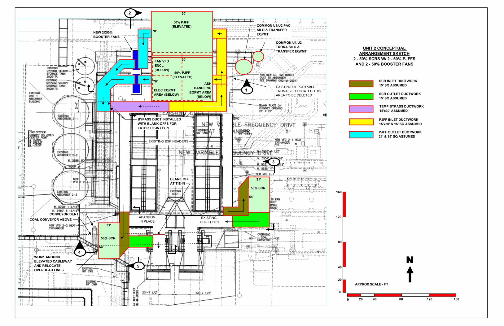
0 20 40 80 160120
0
20
40
80
120
160
APPROX SCALE - FT
N
TEMP BYPASS DUCTWORK 15'x30' ASSUMED
90' 50% PJFF (ELEVATED) 70'
UNIT 2 CONCEPTUAL ARRANGEMENT SKETCH
2 - 50% SCRS W/ 2 - 50% PJFFS AND 2 - 50% BOOSTER FANS
EXISTING DUCT (TYP)
PJFF INLET DUCTWORK 15'x30' & 15' SQ ASSUMED
SCR INLET DUCTWORK 15' SQ ASSUMED
SCR OUTLET DUCTWORK 15' SQ ASSUMED
PJFF OUTLET DUCTWORK 21' & 15' SQ ASSUMED
EXISTING ESP HEADERS
90'
50% PJFF (ELEVATED)70'NEW 2X50%
BOOSTER FANS
WORK AROUND ELEVATED CABLEWAY AND RELOCATE OVERHEAD LINES
COAL CONVEYOR ABOVEABANDONIN PLACE
BYPASS DUCT INSTALLED WITH BLANK-OFFS FOR LATER TIE-IN (TYP)
ASHHANDLING
EQPMT AREA(BELOW)
COMMON U1/U2 TRONA SILO & TRANSFER EQPMT
COMMON U1/U2 PAC SILO & TRANSFER EQPMT
CONVEYOR BENT
31'
50% SCR
54'
BLANK OFF AT TIE-IN
ELEC EQPMT AREA (BELOW)
FAN VFD ENCL (BELOW)
1
2
3
4
5
EXISTING U1 PORTABLE TRONA SILO LOCATED THIS AREA TO BE DELETED
31'
50% SCR
54'

SECTION 1NOT TO SCALE
50% PJFF
+25'
+0'
ELECTRICAL EQUIPMENT AREA (VFD ENCLOSURE BEHIND)
ASH HANDLING EQUIPMENT AREA
ELEVATED SUPERSTRUCTURE SUPPORTING PJFF
50% BOOSTER FAN
UNIT 2 CONCEPTUAL ARRANGEMENT SKETCH
SECTIONS

SECTION 2NOT TO SCALE
50% PJFF
+25'
+0'
50% BOOSTER FAN
AREA FOR RE-ESTABLISHED
ROADWAY
EXISTING PIPERACK
TEMPORARY BYPASS DUCT TO BE DEMOLISHED WHEN PJFF COMPLETE
UNIT 2 CONCEPTUAL ARRANGEMENT SKETCH
SECTIONS
ELEVATED SUPERSTRUCTURE SUPPORTING PJFF
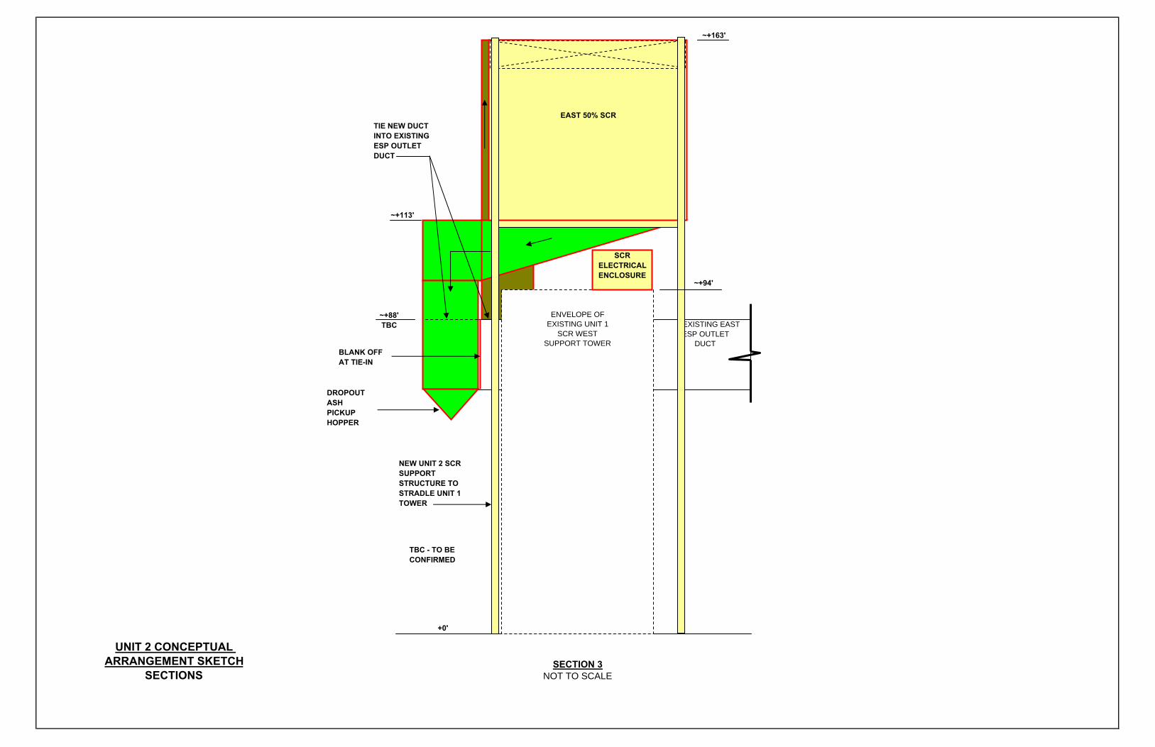
SECTION 3NOT TO SCALE
EXISTING EAST ESP OUTLET DUCT
ENVELOPE OF EXISTING UNIT 1
SCR WEST SUPPORT TOWER
TIE NEW DUCT INTO EXISTING ESP OUTLET DUCT
+0'
~+88'TBC
~+94'
~+163'
TBC - TO BE CONFIRMED
~+113'
NEW UNIT 2 SCR SUPPORT STRUCTURE TO STRADLE UNIT 1 TOWER
UNIT 2 CONCEPTUAL ARRANGEMENT SKETCH
SECTIONS
EAST 50% SCR
BLANK OFF AT TIE-IN
DROPOUT ASH PICKUP HOPPER
SCR ELECTRICAL ENCLOSURE

SECTION 4 SECTION 5NOT TO SCALE NOT TO SCALE
WEST 50% SCR
EXISTING WEST AIR HEATER
INLET DUCT
+0'
~+127'TBC
~+68'TBC
~+88' TBC
TBC - TO BE CONFIRMED
TIE NEW DUCT INTO EXISTING ESP OUTLET DUCT
+0'
~+88'TBC
W.P. 619.5'~+131.5'
~+122'
EXISTING COAL CONVEYOR 3J
~+122'
SCR ELECTRICAL ENCLOSURE
EXISTING CONVEYOR BENT 34J-F
EXISTING WEST ESP RETURN DUCT
EXISTING COAL CONVEYOR 3J
TIE NEW DUCT INTO EXISTING ESP OUTLET DUCT
NEW UNIT 2 WEST SCR SUPPORT TOWER
NEW UNIT 2 WEST SCR SUPPORT TOWER
~+127'TBC
~+72'
DROPOUT ASH PICKUP HOPPER
DROPOUT ASH PICKUP HOPPER
UNIT 2 CONCEPTUAL ARRANGEMENT SKETCH
SECTIONS
SCR ELECTRICAL ENCLOSURE
WEST 50% SCR
EXISTING WEST ESP RETURN DUCT
BLANK OFF AT TIE-IN

LG&E/KU – Ghent Station Air Quality Control Validation Report Appendix A
February 2011 A-4 168908.41.0803
Unit 3 and 4 Arrangements – Option 1
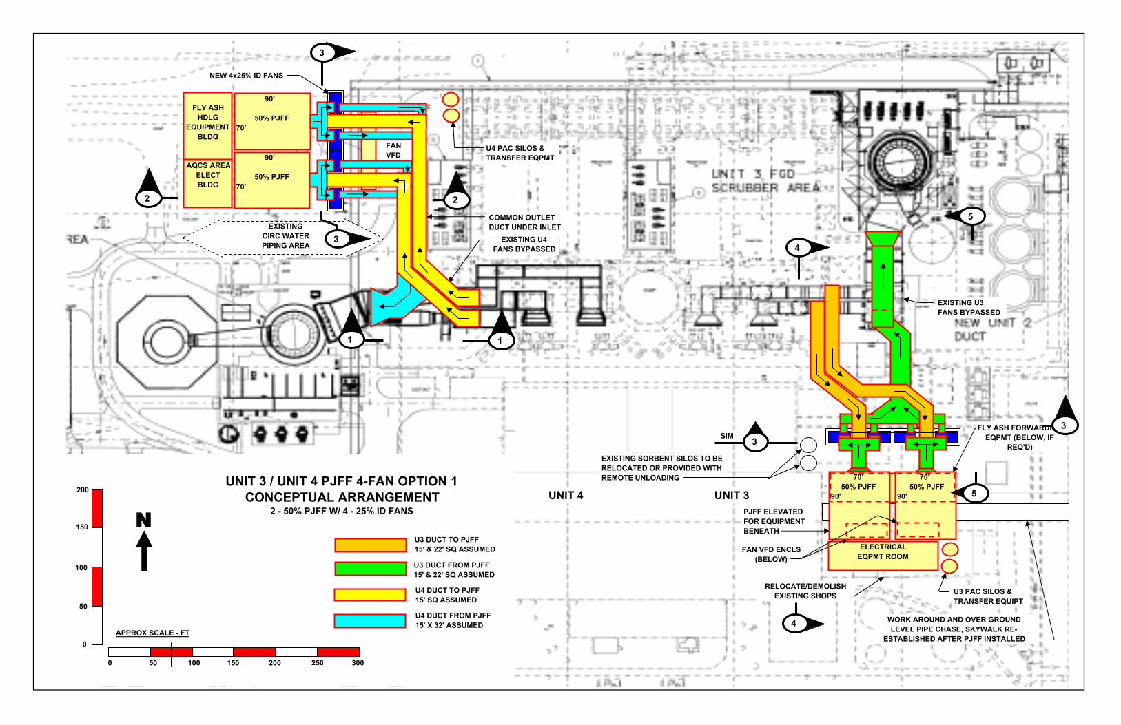
UNIT 3 / UNIT 4 PJFF 4-FAN OPTION 1 CONCEPTUAL ARRANGEMENT
2 - 50% PJFF W/ 4 - 25% ID FANS
0
50
100
150
200
0 50 100 150 200 300250
APPROX SCALE - FT
N
FLY ASH HDLG
EQUIPMENT BLDG
AQCS AREAELECT BLDG
U4 PAC SILOS & TRANSFER EQPMT
EXISTING CIRC WATER PIPING AREA
U3 DUCT TO PJFF 15' & 22' SQ ASSUMED
U3 DUCT FROM PJFF 15' & 22' SQ ASSUMED
U4 DUCT TO PJFF 15' SQ ASSUMED
U4 DUCT FROM PJFF 15' X 32' ASSUMED
COMMON OUTLET DUCT UNDER INLET
EXISTING U4 FANS BYPASSED
NEW 4x25% ID FANS
WORK AROUND AND OVER GROUND LEVEL PIPE CHASE, SKYWALK RE-
ESTABLISHED AFTER PJFF INSTALLED
PJFF ELEVATED FOR EQUIPMENT BENEATH
U3 PAC SILOS & TRANSFER EQUIPT
EXISTING U3 FANS BYPASSED
UNIT 4 UNIT 3
EXISTING SORBENT SILOS TO BE RELOCATED OR PROVIDED WITH REMOTE UNLOADING
FAN VFD
3
2
4
5
RELOCATE/DEMOLISH EXISTING SHOPS
ELECTRICAL EQPMT ROOM
SIM 3
FAN VFD ENCLS (BELOW)
1
FLY ASH FORWARDINGEQPMT (BELOW, IF
REQ'D)
90'
50% PJFF70'
90'
50% PJFF70'
1
2
3
70' 50% PJFF90'
70' 50% PJFF90' 5
3
4

SECTION 1NOT TO SCALE
SECTION 2 SECTION 3NOT TO SCALE NOT TO SCALE
+52'
+44'
+27'
+0'
50% PJFF
+27'
+0'
+44'
ID FAN (TYP OF 4)
ID FAN (TYP OF 3)
CL PJFF
UNIT 3/4 4-FAN PJFF OPTION 1 CONCEPTUAL ARRANGEMENT SKETCH
SECTIONS
CL PJFF

SECTION 4NOT TO SCALE
+68'
+0'
+20'
50% PJFF
+92'
COAL TRANSFER TOWER (BEHIND)
ELECTRICAL EQUIPMENT ROOMID FAN (TYP OF 4)
VEHICLE ACCESS ASH FORWARDING EQPMT AREA (IF REQUIRED)
FAN VFD
ENCLOSURE
GROUND LEVEL
WALKWAY & UTILITY CHASE
ELEVATED SUPERSTRUCTURE SUPPORTING PJFF TO BE COORDINATED WITH GROUND LEVEL WALKWAY AND ACCESS REQUIREMENTS
SKYWALK RE-ESTABLISHED AND INCORPORATED INTO PJFF WALKWAY
UNIT 3/4 4-FAN PJFF OPTION 1 CONCEPTUAL ARRANGEMENT SKETCH
SECTIONS
EXISTING SUMP

SECTION 5NOT TO SCALE
50% PJFF
+0'
ID FAN (TYP OF 4)
+70'
CL +547'-1 5/16"
+47'
BYPASS EXISTING ID FANS
UNIT 3/4 4-FAN PJFF OPTION 1 CONCEPTUAL ARRANGEMENT SKETCH
SECTIONS
LG&E/KU – Ghent Station Air Quality Control Validation Report Appendix A
February 2011 A-5 168908.41.0803
Unit 3 and 4 Arrangements – Option 2

UNIT 3 / UNIT 4 4-FAN PJFF OPTION 2 CONCEPTUAL ARRANGEMENT
1 - 100% PJFF W/ 4 - 25% ID FANS
0
50
100
150
200
0 50 100 150 200 300250
APPROX SCALE - FT
N
205'
PJFF77'
FLY ASH HDLG EQUIPMENT
BLDG
AQCS AREA ELECT BLDG
U4 PAC SILOS & TRANSFER EQPMT
EXISTING CIRC WATER PIPING AREA
U3 DUCT TO PJFF 15' & 22' SQ ASSUMED
U3 DUCT FROM PJFF 15' & 22' SQ ASSUMED
U4 DUCT TO PJFF 15' & 22' SQ ASSUMED
U4 DUCT FROM PJFF 15' & 22' SQ ASSUMED
OUTLET DUCT UNDER INLET DUCT
EXISTING U4 FANS BYPASSED
NEW 2x50% BOOSTER FANS DOWNSTREAM OF PJFF
WORK AROUND AND OVER GROUND LEVEL PIPE CHASE, SKYWALK RE-
ESTABLISHED AFTER PJFF INSTALLED
PJFF ELEVATED FOR TRUCK ACCESS BENEATH
TRUCK ACCESS TO EXISTING SILO
U3 PAC SILO & TRANSFER EQUIPT
EXISTING U3 FANSBYPASSED
UNIT 4 UNIT 3
EXISTING SILOS
3
2
5
205'
PJFF 77'
RELOCATE/DEMOLISH EXISTING SHOPS
ELECTRICAL EQPMT
(BELOW)
4
1
FLY ASH HDLG EQPMT
(BELOW)
FAN VFD
ENCL
NEW 2x50% ID FANS UPSTREAM OF PJFF
REROUTE ROAD AROUND PJFF
2
3
1
FAN VFD
ENCLS
4
5
NEW 2X50% BOOSTER FANS DOWNSTREAM OF PJFF
NEW 2X50% ID FANS UPSTREAM OF PJFF

SECTION 1NOT TO SCALE
SECTION 2 SECTION 3NOT TO SCALE NOT TO SCALE
PJFF
+28'
+0'
+50'
PJFF OUTLET BOOSTER FAN (TYP OF 2)
PJFF OUTLET BOOSTER FAN (TYP OF 2)
CL PJFF
UNIT 3/4 4-FAN PJFF OPTION 2 CONCEPTUAL ARRANGEMENT SKETCH
SECTIONS
PJFF INLET ID FAN (TYP OF 2)
+52'
+44'
+27'
+0'
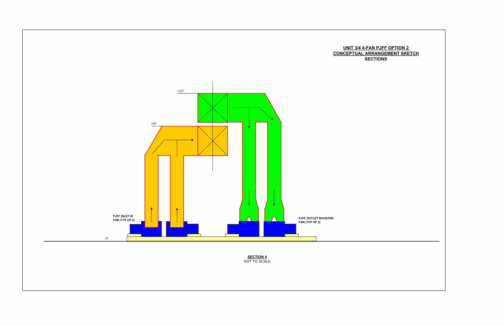
SECTION 4NOT TO SCALE
+0'
+117'
+92'
PJFF OUTLET BOOSTER FAN (TYP OF 2)
PJFF INLET ID FAN (TYP OF 2)
UNIT 3/4 4-FAN PJFF OPTION 2 CONCEPTUAL ARRANGEMENT SKETCH
SECTIONS

SECTION 5NOT TO SCALE
VEHICLE ACCESS
ELEVATED SUPERSTRUCTURE SUPPORTING PJFF TO BE COORDINATED WITHGROUND LEVEL WALKWAY AND ACCESS REQUIREMENTS
100% PJFF
+0'
PJFF OUTLET BOOSTER FAN (TYP OF 2)PJFF OUTLET ID FAN (BEHIND, TYP OF 2)
+70'
CL +547'-1 5/16"
BYPASS EXISTING ID FANS
+47'
'+68'
UNIT 3/4 4-FAN PJFF OPTION 2 CONCEPTUAL ARRANGEMENT SKETCH
SECTIONS

LG&E/KU – Ghent Station Air Quality Control Validation Report Appendix A
February 2011 A-6 168908.41.0803
Unit 3 and 4 Arrangements – Option 3

UNIT 3 / UNIT 4 3-FAN W/ DAMPERS PJFF OPTION 3 CONCEPTUAL ARRANGEMENT
1 - 100% PJFF W/ 3 - 33% ID FANS & 2 - DAMPERS
0
50
100
150
200
0 50 100 150 200 300250
APPROX SCALE - FT
N
205'
PJFF77'
FLY ASH HDLG EQUIPMENT BLDG
AQCS AREA ELECT BLDG
U4 PAC SILOS & TRANSFER EQPMT
EXISTING CIRC WATER PIPING AREA
U3 DUCT TO PJFF 15' & 22' SQ ASSUMED
U3 DUCT FROM PJFF 15' & 22' SQ ASSUMED
U4 DUCT TO PJFF 15' & 22' SQ ASSUMED
U4 DUCT FROM PJFF 15' & 22' SQ ASSUMED
OUTLET DUCT UNDER INLET DUCT
EXISTING U4 FANS BYPASSED
NEW 3x33% ID FANS
WORK AROUND AND OVER GROUND LEVEL PIPE CHASE, SKYWALK RE-
ESTABLISHED AFTER PJFF INSTALLED
PJFF ELEVATED FOR TRUCK ACCESS BENEATH
TRUCK ACCESS TO EXISTING SILO
U3 PAC SILOS & TRANSFER EQUIPT
EXISTING U3 FANS BYPASSED
UNIT 4 UNIT 3
EXISTING SILOS
FAN VFD ENCL
3
2
4
205'
PJFF 77'
RELOCATE/DEMOLISH EXISTING SHOPS
ELECTRICAL EQPMT
(BELOW)
SIM
FAN VFD
ENCL
1
FLY ASH HDLG EQPMT
(BELOW)
MODULATING DAMPER (TYP OF 2)
3 3
4
3
2
1

SECTION 1NOT TO SCALE
SECTION 2 SECTION 3NOT TO SCALE NOT TO SCALE
+52'
+44'
+50'
+28'
+0'
PJFF
+28'
+0'
+50'
ID FAN (TYP OF 3)
PJFF INLET DUCT (BEHIND)
PJFFOUTLETDUCT(BEHIND)
ID FAN (TYP OF 3)
CL PJFF
UNIT 3/4 3-FAN W/ DAMPERS OPTION 3 CONCEPTUAL ARRANGEMENT SKETCH
SECTIONS
MODULATING DAMPER
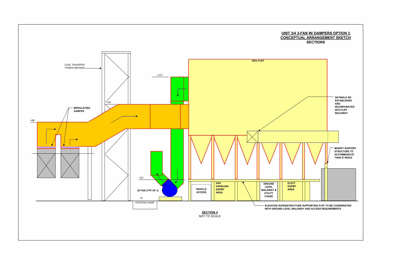
SECTION 4NOT TO SCALE
+68'
+0'
+20'
100% PJFF
+117'
+92'
COAL TRANSFER TOWER (BEHIND)
MODIFY SUPPORT STRUCTURE TO ACCOMMODATE TANK IF REQ'D
ID FAN (TYP OF 3) VEHICLE ACCESS
ASH HANDLING EQPMT AREA
ELECT EQPMT AREA
GROUND LEVEL
WALKWAY & UTILITY CHASE
ELEVATED SUPERSTRUCTURE SUPPORTING PJFF TO BE COORDINATED WITH GROUND LEVEL WALKWAY AND ACCESS REQUIREMENTS
SKYWALK RE-ESTABLISHED AND INCORPORATED INTO PJFF WALKWAY
EXISTING SUMP
MODULATING DAMPER
UNIT 3/4 3-FAN W/ DAMPERS OPTION 3 CONCEPTUAL ARRANGEMENT SKETCH
SECTIONS

LG&E/KU – Ghent Station Air Quality Control Validation Report Appendix B
February 2011 B-1 168908.41.0803
Appendix B Flow Biasing Options

LG&E/KU – Ghent Station Phase II Air Quality Control Study Flow Biasing Options January 24, 2011 Revision B – Issued For Client Review B&V File Number 41.0814.3

LG&E/KU – Ghent Station Flow Biasing Options Introduction
Table of Contents
1.0 Introduction.......................................................................................................... 1-2
1.1 Project Overview ..................................................................................... 1-2
1.2 Objective .................................................................................................. 1-2
1.3 Background.............................................................................................. 1-2
2.0 Flow Biasing Options .......................................................................................... 2-1
2.1 Option 1 ................................................................................................... 2-1
2.2 Option 2 ................................................................................................... 2-2
2.3 Option 3 ................................................................................................... 2-3
3.0 Summary .............................................................................................................. 3-1
Appendix A Plant Layout Sketches ................................................................................ A-1
Figures
Figure 1 – Units 3 and 4 Existing Draft System .............................................................. 1-3
Figure 2 – Option 1: Units 3 and 4 Future Draft System, Two PJFF with Two ID fans Downstream Each ....................................................................... 2-2
Figure 3 – Option 2: Units 3 and 4 Future Draft System, Single PJFF with Two ID fans Upstream and Two Booster Fans Downstream........................... 2-3
Figure 4 – Option 3: Units 3 and 4 Future Draft System, Modulating Dampers Upstream of a Single PJFF with Three ID Fans Downstream................. 2-4
Tables
Table 1 – Ghent Flow Biasing Options Summary ........................................................... 3-2
January 2011 1-1 168908.41.0814.3
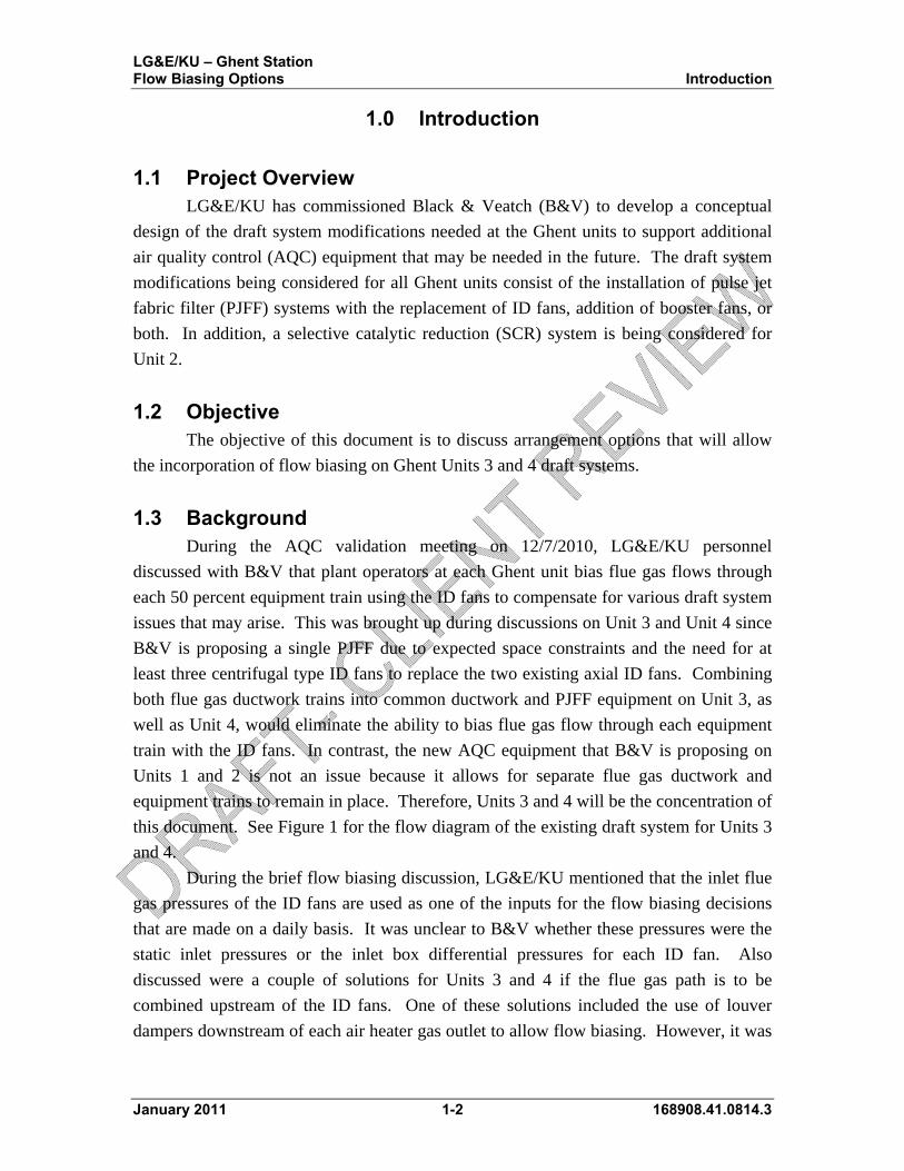
LG&E/KU – Ghent Station Flow Biasing Options Introduction
1.0 Introduction
1.1 Project Overview LG&E/KU has commissioned Black & Veatch (B&V) to develop a conceptual
design of the draft system modifications needed at the Ghent units to support additional
air quality control (AQC) equipment that may be needed in the future. The draft system
modifications being considered for all Ghent units consist of the installation of pulse jet
fabric filter (PJFF) systems with the replacement of ID fans, addition of booster fans, or
both. In addition, a selective catalytic reduction (SCR) system is being considered for
Unit 2.
1.2 Objective The objective of this document is to discuss arrangement options that will allow
the incorporation of flow biasing on Ghent Units 3 and 4 draft systems.
1.3 Background During the AQC validation meeting on 12/7/2010, LG&E/KU personnel
discussed with B&V that plant operators at each Ghent unit bias flue gas flows through
each 50 percent equipment train using the ID fans to compensate for various draft system
issues that may arise. This was brought up during discussions on Unit 3 and Unit 4 since
B&V is proposing a single PJFF due to expected space constraints and the need for at
least three centrifugal type ID fans to replace the two existing axial ID fans. Combining
both flue gas ductwork trains into common ductwork and PJFF equipment on Unit 3, as
well as Unit 4, would eliminate the ability to bias flue gas flow through each equipment
train with the ID fans. In contrast, the new AQC equipment that B&V is proposing on
Units 1 and 2 is not an issue because it allows for separate flue gas ductwork and
equipment trains to remain in place. Therefore, Units 3 and 4 will be the concentration of
this document. See Figure 1 for the flow diagram of the existing draft system for Units 3
and 4.
During the brief flow biasing discussion, LG&E/KU mentioned that the inlet flue
gas pressures of the ID fans are used as one of the inputs for the flow biasing decisions
that are made on a daily basis. It was unclear to B&V whether these pressures were the
static inlet pressures or the inlet box differential pressures for each ID fan. Also
discussed were a couple of solutions for Units 3 and 4 if the flue gas path is to be
combined upstream of the ID fans. One of these solutions included the use of louver
dampers downstream of each air heater gas outlet to allow flow biasing. However, it was
January 2011 1-2 168908.41.0814.3

LG&E/KU – Ghent Station Flow Biasing Options Introduction
also noted that the operation of louver dampers in flue gas streams is known to be
problematic. The item was then tabled until B&V could further review the issue.
Figure 1 – Units 3 and 4 Existing Draft System
January 2011 1-3 168908.41.0814.3

LG&E/KU – Ghent Station Flow Biasing Options Flow Biasing Options
2.0 Flow Biasing Options
A further discussion on flow biasing for Ghent Units 3 and 4 took place on
1/12/2011 with a conference call between LG&E/KU and B&V to better understand the
reasons for flow biasing. As a result of the discussions it was determined that the flow
biasing currently being done between different trains of flue gas draft system components
is heavily desired due to the multitude of conditions that it is used to control. Therefore,
three different draft system layout options were discussed to allow the ability to continue
to bias flows. The three options, discussed further in this document, are as follows:
Option 1: Two separate PJFFs with two ID fans per PJFF
Option 2: One common PJFF with two ID fans upstream and two booster fans
downstream
Option 3: One common PJFF and three ID fans with modulating dampers
upstream of PJFF (B&V initially proposed layout)
This document is intended to document and condense previous discussions and to
provide a basis on which LG&E/KU can decide how best to continue development of the
conceptual design for Units 3 and 4.
2.1 Option 1 With Option 1 the flue gas flow between the two trains remains separated entering
each new 50 percent capacity PJFF, each with its own set of two new 25 percent capacity
ID fans. Figure 2 illustrates this concept and the Option 1 plant layout sketches in
Appendix A show this in more detail. This arrangement offers advantages over the other
two options that will be discussed later. First is that there is no need to install extra
dampers in each flue gas path to bias the flows between each train; the biasing can be
accomplished through the ID fans as configured. Next, all four centrifugal ID fans will
be sized with the same performance characteristics potentially decreasing the cost of the
draft fans. Additionally, in the future, if the plant decides to permanently shutdown the
hot-side ESPs due to temperature drop, leakage, collection issues, etc., the draft system is
set up to accommodate this transition. This is because the draft fans are all downstream
of the PJFF and would still not be subject to high particulate loading. There may be a
need for modifications to the SCR system and/or the air heaters (AH) to accommodate
the much higher particulate loading, however.
A disadvantage associated with Option 1 is that it would likely have the highest
cost of the three options. The incorporation of two PJFFs and an additional ID fan
beyond the three in Option 3 are the main reasons for the higher cost. Another
January 2011 2-1 168908.41.0814.3
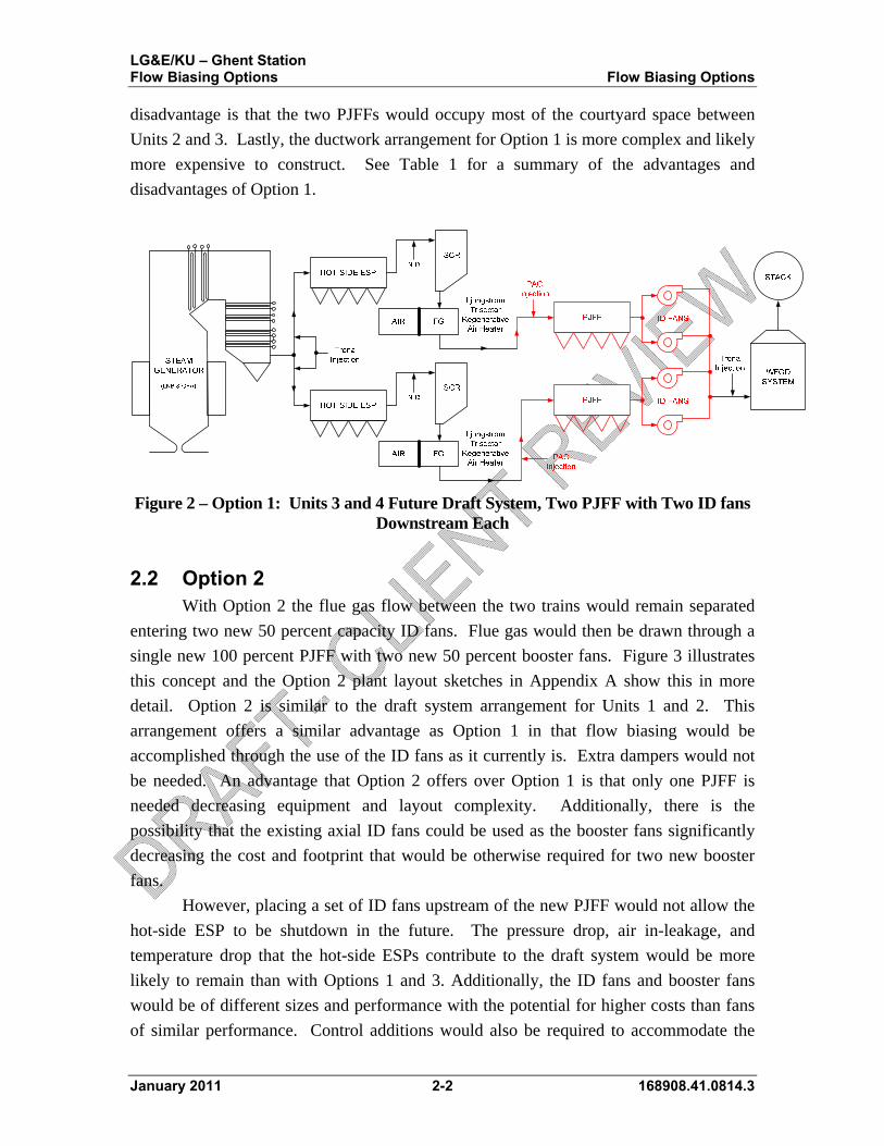
LG&E/KU – Ghent Station Flow Biasing Options Flow Biasing Options
disadvantage is that the two PJFFs would occupy most of the courtyard space between
Units 2 and 3. Lastly, the ductwork arrangement for Option 1 is more complex and likely
more expensive to construct. See Table 1 for a summary of the advantages and
disadvantages of Option 1.
Figure 2 – Option 1: Units 3 and 4 Future Draft System, Two PJFF with Two ID fans Downstream Each
2.2 Option 2 With Option 2 the flue gas flow between the two trains would remain separated
entering two new 50 percent capacity ID fans. Flue gas would then be drawn through a
single new 100 percent PJFF with two new 50 percent booster fans. Figure 3 illustrates
this concept and the Option 2 plant layout sketches in Appendix A show this in more
detail. Option 2 is similar to the draft system arrangement for Units 1 and 2. This
arrangement offers a similar advantage as Option 1 in that flow biasing would be
accomplished through the use of the ID fans as it currently is. Extra dampers would not
be needed. An advantage that Option 2 offers over Option 1 is that only one PJFF is
needed decreasing equipment and layout complexity. Additionally, there is the
possibility that the existing axial ID fans could be used as the booster fans significantly
decreasing the cost and footprint that would be otherwise required for two new booster
fans.
However, placing a set of ID fans upstream of the new PJFF would not allow the
hot-side ESP to be shutdown in the future. The pressure drop, air in-leakage, and
temperature drop that the hot-side ESPs contribute to the draft system would be more
likely to remain than with Options 1 and 3. Additionally, the ID fans and booster fans
would be of different sizes and performance with the potential for higher costs than fans
of similar performance. Control additions would also be required to accommodate the
January 2011 2-2 168908.41.0814.3

LG&E/KU – Ghent Station Flow Biasing Options Flow Biasing Options
booster fans. Similar to Option 1, adding the second set of fans will increase the
complexity and cost of the ductwork. See Table 1 for a summary of the advantages and
disadvantages of Option 2.
Figure 3 – Option 2: Units 3 and 4 Future Draft System, Single PJFF with Two ID fans Upstream and Two Booster Fans Downstream
2.3 Option 3 As previously mentioned, Option 3 is the initial layout that B&V proposed which
is in the Ghent AQC Validation report. In order for flow biasing to be accomplished with
this layout, modulating dampers would need to be installed in a section of the draft
system upstream of the new PJFF where the flue gas paths are still split. Figure 4
illustrates this concept and the Option 3 plant layout sketches in Appendix A show this in
more detail. One advantage of this option that is similar to those discussed for Option 1
includes the use of similarly sized ID fans potentially leading to a cost savings. Also,
similar to Option 2, a single PJFF would be used which is expected to decrease
equipment and layout complexity over a two PJFF arrangement. Similar to Option 1, the
Option 3 arrangement is more conducive to allowing the unit to discontinue the use of the
hot-side ESPs at some time in the future. Some additional advantages consist of the use
of only three ID fans allowing for one less fan foundation, less ductwork, and other
equipment associated with a fourth fan. It is expected that this Option would be the least
expensive of the three options due to the three ID fans and single PJFF. Adding the
modulating dampers to allow for flow biasing should be relatively inexpensive.
There are several disadvantages to this option as well. First, flow biasing through
the use of the ID fans would no longer be available. The flow biasing duties would be
transferred to the dampers creating another resistance in the draft system. Secondly,
working with odd numbers of fans is more challenging from an electrical power and
January 2011 2-3 168908.41.0814.3
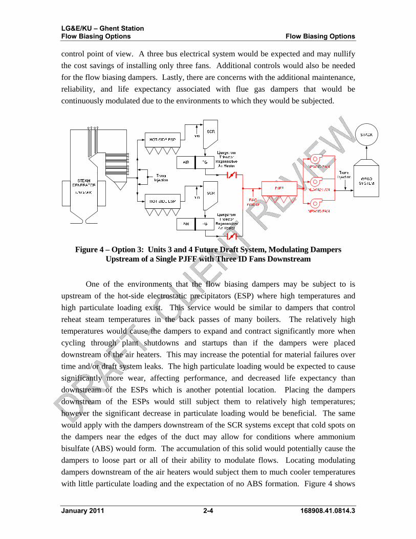
LG&E/KU – Ghent Station Flow Biasing Options Flow Biasing Options
control point of view. A three bus electrical system would be expected and may nullify
the cost savings of installing only three fans. Additional controls would also be needed
for the flow biasing dampers. Lastly, there are concerns with the additional maintenance,
reliability, and life expectancy associated with flue gas dampers that would be
continuously modulated due to the environments to which they would be subjected.
Figure 4 – Option 3: Units 3 and 4 Future Draft System, Modulating Dampers Upstream of a Single PJFF with Three ID Fans Downstream
One of the environments that the flow biasing dampers may be subject to is
upstream of the hot-side electrostatic precipitators (ESP) where high temperatures and
high particulate loading exist. This service would be similar to dampers that control
reheat steam temperatures in the back passes of many boilers. The relatively high
temperatures would cause the dampers to expand and contract significantly more when
cycling through plant shutdowns and startups than if the dampers were placed
downstream of the air heaters. This may increase the potential for material failures over
time and/or draft system leaks. The high particulate loading would be expected to cause
significantly more wear, affecting performance, and decreased life expectancy than
downstream of the ESPs which is another potential location. Placing the dampers
downstream of the ESPs would still subject them to relatively high temperatures;
however the significant decrease in particulate loading would be beneficial. The same
would apply with the dampers downstream of the SCR systems except that cold spots on
the dampers near the edges of the duct may allow for conditions where ammonium
bisulfate (ABS) would form. The accumulation of this solid would potentially cause the
dampers to loose part or all of their ability to modulate flows. Locating modulating
dampers downstream of the air heaters would subject them to much cooler temperatures
with little particulate loading and the expectation of no ABS formation. Figure 4 shows
January 2011 2-4 168908.41.0814.3

LG&E/KU – Ghent Station Flow Biasing Options Flow Biasing Options
January 2011 2-5 168908.41.0814.3
dampers in this location. However, the potential for the condensation of acid gases
considerably increases with the cooler temperatures subjecting the dampers to a corrosive
environment. If Option 3 is chosen, further discussions will need to take place to
determine the location in the split draft system that these dampers should be placed with
the greatest potential to minimize wear and maintenance. See Table 1 for a summary of
the advantages and disadvantages of Option 3.

LG&E/KU – Ghent Station Flow Biasing Options Summary
3.0 Summary
In review, Option 1 incorporates the use of two separate fabric filters with the use
of two ID fans per fabric filter. Option 2 uses only one common fabric filter with two ID
fans upstream and two booster fans downstream. Option 3 is the layout that B&V
initially proposed but with the incorporation of modulating dampers. Figures 2, 3, and 4,
as well as the plant layout sketches in Appendix A, illustrate these options. Any of these
three options discussed would allow flue gas flow biasing up through the air heaters on
Ghent Units 3 and 4 and as the detailed description of each option revealed, there are a
multitude of advantages and disadvantages associated with each. Furthermore, B&V is
confident that each of the three options would fit within the site real estate available with
reasonable costs associated with the appropriate site preparations and modifications.
Table 1 in this document has been created to summarize these advantages and
disadvantages, or pros and cons.
B&V requests that LG&E/KU review the pros and cons of these three options and
provide comments. If needed, another teleconference can be setup to allow further
discussions. Further discussion and possibly a chosen option will allow LG&E/KU and
B&V to have a more defined direction to proceed forward with to allow flue gas flow
biasing.
January 2011 3-1 168908.41.0814.3

LG&E/KU – Ghent Station Flow Biasing Options Summary
January 2011 3-2 168908.41.0814.3
Table 1 – Ghent Flow Biasing Options Summary
Options Option 1 Two PJFFs 4 ID Fans
Option 2 Common PJFF
2 ID & 2 Booster Fans
Option 3 Common PJFF
3 ID Fans & Dampers
Pros Extra dampers in flue gas stream not required
All draft fans are same size and performance
Continued flow biasing through ID fan control
Can abandon hot-side ESP in future (potential SCR and AH modifications)
Separate dampers in flue gas stream not required
Continued flow biasing through ID fan control
Existing axial ID fans could be used as boosters decreasing cost and footprint
Arranged similarly to Unit 2
Single PJFF – decreased equipment & layout complexity
Least expensive
All draft fans are same size and performance
Can abandon hot-side ESP in future (potential SCR and AH modifications)
Single PJFF – decreased equipment & layout complexity
Cons Most expensive
More complex ductwork and equipment arrangement
Occupies most courtyard space between Units 2 and 3
ID and Booster fans different sizes and performance
Cannot abandon hot-side ESP in future
Control additions required for booster fans
More complex ductwork arrangement
Inability to flow bias with ID fans
Damper reliability concerns
Additional damper maintenance
Damper life expectancy concerns
Added pressure drop in flue gas stream
Additional controls required for dampers
Odd fan number, more challenging electrical & control scheme


![Hoine 2014, ] Fate (I).pdf · Richard Taylor (Marquette University/ KU Leuven): Providence in Averroes PART 7: THE MEDIEVAL LATIN TRADITION ... Henry of Ghent on Fatalism and Naturalism](https://img.pdfslide.us/doc/110x75/5aea11487f8b9a36698c8aae/hoine-2014-fate-ipdfrichard-taylor-marquette-university-ku-leuven-providence.jpg)