Embed Size (px)
Citation preview

LG&E Services CompanyLG&E Services CompanyContract No. 501654Contract No. 501654
Mill Creek FGD Performance Upgrade StudyMill Creek FGD Performance Upgrade Study
February 2011February 2011
Assess the feasibility of upgrading the Mill Creek Units 1 & 2 Assess the feasibility of upgrading the Mill Creek Units 1 & 2 FGDFGD’’ss
and upgrading the existing Mill Creek 4 FGD and and upgrading the existing Mill Creek 4 FGD and utilizing it for Mill Creek Unit 3utilizing it for Mill Creek Unit 3

LLGG&&EE SSeerrvviicceess CCoommppaannyy CCoonnttrraacctt NNoo.. 550011665544
MMiillll CCrreeeekk FFGGDD PPeerrffoorrmmaannccee UUppggrraaddee SSttuuddyy
“Assess the feasibility of upgrading the Mill Creek Units 1&2 FGD’s and upgrading the existing Mill Creek
4 FGD and utilizing it for Mill Creek Unit 3”
LG&E Services Company Contract No. 501654
Mill Creek FGD Performance Upgrade Study
Table of Contents February 15, 2011
1.0 Executive Summary 2.0 BPEI WFGD Technology Features and Benefits
2.1 Extensive 3-D Modeling Technology 2.2 Dual Flow Nozzles 2.3 Wall Baffles 2.4 Agitators 2.5 Mist Eliminators 2.6 Recycle Pumps
3.0 Base Case – Existing Absorber Design and Operation
3.1 Executive Summary – Base Case 3.2 System Description 3.3 Current Process Operation 3.4 Spray Header Arrangement / Spray Nozzle Coverage 3.5 Recycle Pump Performance 3.6 Absorber Inlet Design 3.7 Predicted Absorber Performance 3.8 Predicted Absorber Performance 3.9 Construction
4.0 Case 2 – Required Equipment Modifications to Reliably Achieve 96% SO2 Removal
4.1 Executive Summary – Case 2, 96% SO2 Removal 4.2 Case 2 – Work Scope 4.3 Spray Header Arrangement / Spray Nozzle Coverage 4.4 Wall Baffles 4.5 Liquid-to-Gas Ration 4.6 Absorber Solids / Liquid Residence Time 4.7 Oxidation Air Blowers and Agitators 4.8 Construction
5.0 Case 3 – Maximum Achievable SO2 Removal Efficiency
5.1 Executive Summary 5.2 Case 3 – Scope of Work 5.3 Optimization of Absorber General Arrangement 5.4 Impact of Reagent Grind Size 5.5 Impact of Organic Acid 5.6 Performance Testing and Modeling 5.7 Construction

6.0 Construction Plan 7.0 Budget Price 8.0 Project Schedule Attachments
– Basis of Design Description – Process Flow Diagrams – Absorber System General Arrangement Drawings – Description of Equipment being Modified – Work Breakdown Structure – Overall Project Schedule – Construction & Outage High Level Schedule – Budget Engineering Procurement and Construction Estimate
1 EXECUTIVE SUMMARY Babcock Power Environmental Inc. (BPEI) has conducted an extensive evaluation of the existing Wet Flue Gas Desulfurization (WFGD) Systems at Louisville Gas and Electric’s (LG&E’s) Mill Creek Generating Station, Units 1, 2 and 4. The purpose of the evaluation was to determine the feasibility of modifying the existing WFGD equipment to enhance the overall SO2 emissions performance. BPEI was requested to prepare three primary options for LG&E’s consideration, as follows:
o Base Case – Current SO2 Removal Efficiency
o Case 2 – System Upgrade – Target: 96% SO2 Removal Efficiency
o Case 3 – System Optimization Upgrade: 98% SO2 Removal Efficiency BPEI evaluated multiple alternatives to accomplish LG&E’s objectives, from minimal change to extensive retrofit, and presents in this report the most favorable options for LG&E’s consideration. BPEI utilized proprietary process software modeling as well as graphical depictions of each phase and any required process infrastructure upgrades. Discussions with plant engineers and reviews of existing plant equipment provided the necessary information to develop a baseline performance model from which to launch the analysis of each option. The report also includes the following Project Deliverables:
Basis of Design Description Process Flow Diagrams Absorber System General Arrangement Drawings Description of Equipment being Modified Work Breakdown Structure Overall Project Schedule Construction and Outage High Level Schedule Budget Engineering, Procurement and Construction Estimate
The evaluation was based on the flue gas from Unit 3 being routed to the existing Unit 4 WFGD and a new WFGD installed to condition the flue gas from Unit 4. For the purposes of this report and in regard to scrubber modifications, “Unit 3” refers the Unit 3 boiler train ducted to the current Unit 4 WFGD system. Unit Descriptions Mill Creek Units 1 and 2 are 330 MW each, controlled circulation, pulverized coal fired boilers, manufactured by Combustion Engineering. They have been in service since 1972 and 1975, respectively. During operation, flue gas exits the air heaters and passes through the ESP, Booster Fans and WFGD and then exits through the stack. The original WFGD systems were provided by Combustion Engineering and have been modified multiple times throughout their operational
Page 1 of 59

history. Recently, spray headers were modified and perforated trays added between spray levels 1 and 2. Today, Units 1 and 2 operate with all spray levels in service. Mill Creek Unit 3 is a 425 MW pulverized coal fired boiler, manufactured by Babcock & Wilcox Co. It has been in service since 1978. Flue gas exits the air heaters and passes through the ESP, ID Fan and WFGD and then exits through the stack. This unit also includes an SCR System that was designed and supplied by Riley Power Inc. (RPI), a Babcock Power Inc. Company. Today, Units 1 and 2 operate with all spray levels in service. The Units burn bituminous coal with an SO2 level of 5.4 lb./MMBtu. The reported SO2 removal is 90-92%, with the reaction tank pH normally set to 5.7. This evaluation will utilize a design coal that has an SO2 level of 6.3 lb./MMBtu. Base Case - Current SO2 Removal Efficiency Technical Description – The task objective of the Base Case is to determine the maximum achievable SO2 efficiency without performing modifications to the existing equipment, based on a specified design coal with an SO2 level of 6.3 lb./MMBtu. The work associated with the Base Case has been completed by BPEI and is presented in this report. Engineering Scope of Work – The mechanisms for achieving the required performance are optimization of the spray coverage and droplet distribution, while maintaining droplet size for peak liquid-to-gas interaction. This is performed by modifying some of the existing equipment and adding new equipment. BPEI modeled the existing absorber systems on Mill Creek Units 1, 2, and 3 (Unit 3 flue gas to be redirected to existing Unit 4 WFGD system) using proprietary software and data obtained from plant personnel to create a realistic baseline performance model. BPEI analyzed performance of the model, altering key variables such as flue gas flow, coal sulfur content, recycle pump flow and pressure, recycle spray nozzle type, nozzle spray angles, nozzle coverage, etc. to determine what modifications to the existing systems would provide the most economical reliable performance enhancements for each system. The base model also provides critical feedback to the design engineers to confirm that theories and calculations used in the model are accurate and appropriate as a starting point for performance enhancement using BPEI’s proven techniques. The evaluation was based on the flue gas from Unit 3 being routed to the existing Unit 4 WFGD and a new WFGD installed to condition the flue gas from Unit 4. Performance – Based on BPEI’s evaluation of the existing equipment and performance capabilities, it has been determined that Units 1 and 2 can be expected to achieve a maximum 88% SO2 removal. Unit 3 can be expected to achieve a maximum 91% SO2 removal. Both of these values are based on a design coal that has an SO2 level of 6.3 lb./MMBtu. The results are based on the spray nozzles and recycle pumps operating as designed. Also, the results reflect a plant modification to route the flue gas from Unit 3 to the Unit 4 WFGD, which has an absorber with 25% additional capacity. The higher removal in Unit 3 is attributed to this modification.
Page 2 of 59

Case 2 – System Upgrade – Target: 96% SO2 Removal Efficiency Technical Description – The task objective of Case 2 was to provide to LG&E the most economical, reliable method to obtain 96% SO2 removal for each of the Mill Creek Units. BPEI modeled the existing absorber systems on Mill Creek Units 1, 2, and 3 (Unit 3 flue gas to be redirected to existing Unit 4 WFGD system) using proprietary software and data obtained from plant personnel to create a realistic baseline performance model. The process parameters were then modified using BPEI’s historical experience as follows: Units 1 and 2:
Change Spray Level 1 nozzles from down-only to dual-flow, double-down nozzles. Change Spray Level 2 nozzles from down-only to dual-flow, up-down nozzles. Change Spray Level 3 nozzles from down-only to dual-flow, up-down nozzles. Change Spray Level 4 nozzles from down-only to dual-flow, double-down nozzles. Change spray nozzle angle on Units 1 and 2 from 80o to 120o. Add wall baffles to Spray Levels 2 and 3.
Unit 3
Change Spray Level 1 nozzles from down-only to dual-flow, double-down nozzles. Change Spray Level 2 nozzles from down-only to dual-flow, up-down nozzles. Change Spray Level 3 nozzles from down-only to dual-flow, up-down nozzles. Change Spray Level 4 nozzles from down-only to dual-flow, double-down nozzles. Add wall baffles to Spray Levels 2 and 3.
The model was then used to determine the required recycle pump flow to achieve 96% SO2 removal. Units 1 and 2
Increase the recycle pump capacity from all at 600 hp to 3 pumps at 500 hp and 5 pumps at 700 hp resulting in a change to the Liquid-to-Gas (L/G) ratio, from 112 gal/kacf to 141 gal/kacf. The recycle pump capacity change in Units 1 and 2 will alter the Liquid-to-Gas (L/G) ratio. Generally L/G ratio trends with removal rate, therefore increasing the flow through the recycle pumps and nozzles corresponds to greater SO2 removal.
Unit 3
No change to the recycle pump capacity is required. BPEI will install agitators on each reaction tank, replacing the existing sparger system, which has a tendency to clog and hinder performance.
Page 3 of 59

Unit 1
Install six (6) agitators on each reactor tank. Unit 2
Install five (5) agitators on each reactor tank. Several chemical and reaction rate modifications were analyzed, namely liquids residence time and solids residence time. Optimum values for each of these reaction rate parameters have been worked into the existing scrubber operation by revising current ranges for operational level in the reaction tanks, absorber slurry solids ranges, and limestone grind fineness. Finally the forced oxidation system was evaluated with emphasis on achieving superior mixing of injected oxidation air, suspension of slurry in the vessel, and complete oxidation of SO2 removed by the absorber. The results of this analysis recommend the following operating changes: Units 1 and 2
Increase absorber slurry solids from 10-12% to 14-16% RETURN TO ORIGINAL DESIGN
Increase absorber reaction tank level from 31.5’ to 35.5’ RETURN TO ORIGINAL DESIGN
Unit 3
Increase absorber slurry solids from 10-12% to 14-16% Increase absorber reaction tank level from 15’ to 18’
Performance – Based on BPEI’s evaluation of the existing equipment and performance capabilities and the modeling effort described above, it has been determined that all three units can be expected to achieve the 96% SO2 removal target. These values are based on a design coal that has an SO2 level of 6.3 lb./MMBtu. Also, the results reflect a plant modification to route the flue gas from Unit 3 to the Unit 4 WFGD, which has an absorber with 25% additional capacity. Engineering Scope of Work – BPEI will perform engineering activities associated with the changes noted above. BPEI will also perform CFD modeling to determine the modifications required to the absorber inlet and confirm the spray nozzle layout and coverage area.
Page 4 of 59

Procurement Scope of Work – The materials required to modify the WFGD and achieve the target performance of 96% SO2 removal efficiency are detailed in the table below: CASE 2 LIST OF MATERIALS Unit 1 Unit 2 Unit 3
Description Size Qty Units Qty Units Qty Units
Slurry Recycle System
Recycle Pumps 700 HP 3 ea. 3 ea.
Recycle Pumps 800 HP 5 ea. 5 ea.
Recycle Discharge Piping 30" 2000 LF 2000 LF
Recycle Suction Pipe/Flanges 30" 8 ea. 8 ea.
Recycle System Valves and Inline Equipment 30" TBD TBD
Spray Nozzles (double down) 120o spray 168 ea. 168 ea. 288 ea.
Spray Nozzles (bi-directional) 120o spray 168 ea. 168 ea. 288 ea.
Wall Baffles
Wall Baffles 4 ea. 4 ea. 8 ea.
Oxidation Air System
Oxidation Air Lances 8" x 40" lg. 6 ea. 6 ea. 10 ea.
Air Lance Supports 6 ea. 6 ea. 10 ea.
Air Piping External to Sump 20" C.S. 1000 LF 1000 LF TBD LF
Air Piping Hangers 59 ea. 59 ea. TBD ea.
Agitators 6 ea. 6 ea. 10 ea.
Construction Plan – Prior to construction BPEI will integrate engineering and fabrication into a detailed fabrication plan. The plan will consider constructability, value engineering, estimating, scheduling, safety, quality, project controls and execution. The objective is to assure that construction is a seamless part of the project delivery. Following mobilization, BPEI will perform pre-construction activities, including receipt of materials, erection of scaffolding and installation of the recycle pump foundations. The remaining activities will be completed during the outage, which is considered of sufficient duration to complete all of the work. The major work activities include the following: Units 1 and 2
Replace existing recycle pumps and piping with new recycle pumps and associated piping
Replace existing spray nozzles with new spray nozzles Install new wall baffles at Spray Levels 2 and 3 Remove existing spargers Install new agitators and oxidation air lances, and associated piping
Page 5 of 59

Unit 3
Replace existing spray nozzles with new spray nozzles Install new wall baffles at Spray Levels 2 and 3 Remove existing spargers Install new agitators and oxidation air lances, and associated piping
Construction will entail four (4) months of pre-outage activity followed by a 3-week outage.
The pre-outage construction utilizes one (1) shift, ten (10) hours per shift, five (5) days per week.
The outage construction utilizes two (2) shifts, ten (10) hours per shift, six (6)
days per week. Cost – The Rough Order of Magnitude (ROM) estimate for labor, materials and construction for each unit is as follows: Unit 1 - $10,541,512 Unit 2 - $10,632,006 Unit 3 - $14,035,835 Case 3 – System Optimization Upgrade: 98% SO2 Removal Efficiency Technical Description – The task objective of Case 3 was to provide to LG&E the most economical, reliable method to obtain 98% SO2 removal for each of the Mill Creek Units, which considered the maximum attainable performance. BPEI modeled the existing absorber systems on Mill Creek Units 1, 2, and 3 (Unit 3 flue gas to be redirected to existing Unit 4 WFGD system) using proprietary software and data obtained from plant personnel to create a realistic baseline performance model. The process parameters were then modified using BPEI’s historical experience. Spray header layout and nozzle selection are optimized based on the overall absorber shell dimensions for absolute maximum performance based on the existing reactor tower dimensions. For Units 1 & 2, recycle pumps are pushed further and piping is resized for greater flow to increase L/G significantly over the original and 96% removal option. Unit 3 does not require higher L/G ratio to maximize SO2 removal. Spray header spacing is increased and placement is altered to allow for multiple levels of bidirectional nozzles, which have proven to be superior in performance compared to down-only nozzles. Spray header layout is altered to provide added spray density and prevent any holes in spray coverage by moving the position of individual nozzles on the headers.
Page 6 of 59

Units 1 and 2:
Move Spray Level 1 from below the tray to 5’ above the tray Space all 4 spray levels 5’ apart Stagger spray header layout Increase spray density by increasing the number of nozzles per spray level from 42 to 54 Change Spray Level 1 nozzles from down-only to dual-flow, double-down nozzles. Change Spray Level 2 nozzles from down-only to dual-flow, up-down nozzles. Change Spray Level 3 nozzles from down-only to dual-flow, up-down nozzles. Change Spray Level 4 nozzles from down-only to dual-flow, double-down nozzles. Change interior nozzle spray angle from 80o to 120o Change wall nozzle spray angle from 80o to 90o Decrease spray pressure from 10 psig to 8 psig Add wall baffles to Spray Levels 2 and 3.
Unit 3
Move Spray Level 1 from below the tray to 5’ above the tray Space all 4 spray levels 5’ apart Stagger spray header layout Increase spray density by increasing the number of nozzles per spray level from 36 to 52 Change Spray Level 1 nozzles from down-only to dual-flow, double-down nozzles. Change Spray Level 2 nozzles from down-only to dual-flow, up-down nozzles. Change Spray Level 3 nozzles from down-only to dual-flow, up-down nozzles. Change Spray Level 4 nozzles from down-only to dual-flow, double-down nozzles. Change wall nozzle spray angle from 120o to 90o Decrease spray pressure from 10 psig to 8 psig Add wall baffles to Spray Levels 2 and 3.
The model was then used to determine the required recycle pump flow to achieve 96% SO2 removal. Units 1 and 2
Increase the recycle pump capacity from all at 600 hp to 3 pumps at 500 hp and 5 pumps at 700 hp resulting in a change to the Liquid-to-Gas (L/G) ratio, from 112 gal/kacf to 144 gal/kacf. The recycle pump capacity change in Units 1 and 2 will alter the Liquid-to-Gas (L/G) ratio. Generally L/G ratio trends with removal rate, therefore increasing the flow through the recycle pumps and nozzles corresponds to greater SO2 removal.
Unit 3
Replace the recycle pump gear boxes to increase capacity.
Page 7 of 59

BPEI will install agitators on each reaction tank, replacing the existing sparger system, which has a tendency to clog and hinder performance and add new mist eliminators. Unit 1
Install six (6) agitators on each reactor tank. Install mist eliminators
Unit 2
Install five (5) agitators on each reactor tank. Install mist eliminators
Several chemical and reaction rate modifications were analyzed, namely liquids residence time and solids residence time. Optimum values for each of these reaction rate parameters have been worked into the existing scrubber operation by revising current ranges for operational level in the reaction tanks, absorber slurry solids ranges, and limestone grind fineness. Finally the forced oxidation system was evaluated with emphasis on achieving superior mixing of injected oxidation air, suspension of slurry in the vessel, and complete oxidation of SO2 removed by the absorber. The results of this analysis recommend the following operating changes: Units 1 and 2
Increase absorber slurry solids from 10-12% to 14-16% RETURN TO ORIGINAL DESIGN
Increase absorber reaction tank level from 31.5’ to 35.5’ RETURN TO ORIGINAL DESIGN
Unit 3
Increase absorber slurry solids from 10-12% to 14-16% Increase absorber reaction tank level from 15’ to 18’
Performance – Based on BPEI’s evaluation of the existing equipment and performance capabilities and the modeling effort described above, it has been determined that all three units can be expected to achieve the 98% SO2 removal efficiency These values are based on a design coal that has an SO2 level of 6.3 lb./MMBtu. Also, the results reflect a plant modification to route the flue gas from Unit 3 to the Unit 4 WFGD, which has an absorber with 25% additional capacity. Engineering Scope of Work – BPEI will perform engineering activities associated with the changes noted above. BPEI will also perform CFD modeling to determine the modifications required to the absorber inlet and confirm the spray nozzle layout and coverage area.
Page 8 of 59

Procurement Scope of Work – The materials required to modify the WFGD and achieve the target performance of 98% SO2 removal efficiency are detailed in the table below:
CASE 3 LIST OF MATERIALS Unit 1 Unit 2 Unit 3
Description Size Qty Units Qty Units Qty Units
Slurry Recycle System
Recycle Pumps 700 HP 3 ea. 3 ea.
Recycle Pumps 800 HP 5 ea. 5 ea.
Gear Boxes 8 ea.
Recycle Discharge Piping 30" TBD LF TBD LF
Recycle Suction Pipe/Flanges 30" 8 ea. 8 ea.
Recycle System Valves and Inline Equipment 30" TBD TBD
Spray Nozzles (double down) 120o spray 324 ea. 324 ea. 624 ea.
Spray Nozzles (bi-directional) 120o spray 108 ea. 108 ea. 208 ea.
Spray Headers 8 ea. 8 ea. 16 ea.
Spray Pipe Hangers TBD TBD TBD
Wall Baffles
Wall Baffles 4 ea. 4 ea. 8 ea.
Oxidation Air System
Oxidation Air Lances 8" x 40" lg. 6 ea. 6 ea. 10 ea.
Air Lance Supports 6 ea. 6 ea. 10 ea.
Air Piping External to Sump 20" C.S. 1000 LF 1000 LF TBD LF
Air Piping Hangers 59 ea. 59 ea. TBD ea.
Agitators 6 ea. 6 ea. 10 ea.
Absorber Shell and Ductwork Modifications
Outlet Expansion Joint 88 LF 88 LF TBD
317L Absorber Shell 16,744 sq. ft. 16,744 sq. ft.
Absorber Reheater Section 1 Lot 1 Lot 1 Lot
DV210 Mist Eliminator and Spray Wash System TBD TBD TBD
Construction Plan – Prior to construction BPEI will integrate engineering and fabrication into a detailed fabrication plan. The plan will consider constructability, value engineering, estimating, scheduling, safety, quality, project controls and execution. The objective is to assure that construction is a seamless part of the project delivery. Following mobilization, BPEI will perform pre-construction activities, including receipt of materials, erection of scaffolding and installation of the recycle pump foundations. The remaining activities will be completed during the outage, which is considered of sufficient duration to complete all of the work. The major work activities include the following:
Page 9 of 59

Units 1 and 2
Replace existing recycle pumps and piping with new recycle pumps and associated piping
Replace existing spray nozzles with new spray nozzles Install new wall baffles at Spray Levels 2 and 3 Remove existing spargers Install new agitators and oxidation air lances, and associated piping Perform absorber shell and duct modifications
Unit 3
Replace existing spray nozzles with new spray nozzles Install new wall baffles at Spray Levels 2 and 3 Remove existing spargers Install new agitators and oxidation air lances, and associated piping Perform absorber shell and duct modifications
Construction will entail six (6) six months of pre-outage activity followed by a 3-week outage.
The pre-outage construction utilizes one (1) shift, ten (10) hours per shift, five (5) days per week.
The outage construction utilizes two (2) shifts, ten (10) hours per shift, seven (7)
days per week. Cost – The Rough Order of Magnitude (ROM) estimate for labor, materials and construction for each unit is as follows: Unit 1 - $20,428,467 Unit 2 - $20,567,445 Unit 3 - $32,944,117 Summary Table 1 summarizes all planned modifications for each option analyzed in the feasibility study. Differences between Units 1, 2 and 3 are noted where applicable.
Page 10 of 59

Base Case
As Installed Case 2
96% Removal Case 3
Maximum Removal
Spray Header Location
No Change (1 spray header below the tray)
No Change All 4 headers installed above the tray spaced 5’ apart
Spray Header Arrangement
Stacked (As installed) Stacked (As installed) Staggered Layout
Spray Nozzle Layout
As installed No Change Increase Spray Density
Type of Spray Nozzles
No Change
Level 1: Double-Down Level 2: Up/Down Level 3: Up/Down Level 4: Double-Down
Level 1: Up/Down Level 2: Up/Down Level 3: Up/Down Level 4: Double-Down
Spray Angle U1&2: All 80o U3: All 120o
U1&2&3:Interior: 120o Wall: 120o
U1&2&3:Interior: 120o Wall: 90o
Spray Pressure 10 psig 10 psig 8 psig
Wall Rings None Installed at Spray Levels 2 & 3
Installed at Spray Levels 2 & 3
Absorber Tray No Change No Change No Change Absorber Solids 10-12% 14-16% 14-16%
Absorber Level U1&2: 31.5’ U3:15’
U1&2: 35.5’ U3:18’
U1&2: 35.5’ U3:18’
L/G Ratio U1&2: 112 gal/kacf U3: 151 gal/kacf
U1&2: 141 gal/kacf U3: 151 gal/kacf
U1&2: 144 gal/kacf U3: 151 gal/kacf
Recycle Pumps U1&2: No Change U3: U4 No Change
U1&2: New Pumps and Piping or Alternative U3: No Change
U1&2: New Pumps and Piping U3: New Gear Boxes
Absorber Inlet Duct
No Change Modify, as required, based on modeling
Modify, as required, based on modeling
ME/Reheater No Change No Change Remove reheat section and supply ME section
Oxidation Air Blower/Agitators
No Change No change to blower. Modify piping to match air lances w/ agitators
No change to blower. Modify piping to match air lances w/ agitators
Predicted SO2
Removal Performance
U1&2: 88% U3: 91% (in U4 abs)
96% +98%
Table 1: Mill Creek Upgrades Summary
Page 11 of 59

2 BPEI WFGD Technical Features and Benefits All WFGDs utilize the same fundamental technology for SO2 absorption. Where BPEI’s design and performance differ from others is in the amount of power and liquid required to achieve the maximum SO2 removal efficiency. BPEI maximizes the contact between the gas and the absorptive liquid by optimizing the design of the spray zone and using wall rings to eliminate “gas sneakage.” This maximizes the utilization of each droplet, while minimizing power consumption from the draft and recycle systems. BPEI utilizes both co-current and counter-current spray nozzles, in addition to absorber wall rings, to continuously achieve high SO2 removals. This performance has been demonstrated at multiple installations. While many of these components and features are common to open spray tower technologies, the unique design configurations employed by BPEI provide the ability to reliably produce high removal efficiencies. To identify how BPEI achieves these results, each of the critical design components is described below: 2.1 Extensive 3-D Modeling Technology BPEI uses an absorber flue gas inlet configuration that effectively introduces the flue gas to the absorber below the first spray level and distributes it uniformly over the entire cross-sectional area of the absorber. This avoids excessive deposits of solids in the ‘wet-dry’ zone where the incoming hot gases contact the slurry spray flow.
Hood Location Spray Flowing Down Absorber Wall and Away from Inlet Duct Inlet Gas Flow
Floor of Inlet
BPEI makes extensive use of 3-D modeling technology. From past experience, BPEI has discovered that physical and/or computational models are an important tool in developing the design of WFGD systems. Applications of modeling include: The prediction of gas distribution at the absorber inlet and into the first spray level.
Page 12 of 59

The prediction of recirculation tank agitator performance as it relates to both suspension of solids and distribution of oxidation air for maximum effectiveness.
Optimization of gas and spray nozzles droplet distribution and interaction through the absorber.
Without Droplets Droplets With Droplets
The liquid film resistance in the liquid-to-gas (L/G) interface is the limiting factor that regulates the rate at which the SO2 absorption occurs. Beyond the (L/G) ratio, the absorption section of the WFGD system must also be designed to maximize the contact between the liquid and the incoming flue gas. High efficiencies are accomplished by designing the spray zone with dual-directional, wide-angle, hollow-cone spray nozzles. This arrangement provides: Excellent liquid distribution over the entire spray level cross-sectional area, ensuring that all
the flue gas is treated. A staggered spray pattern from one level to the next, avoiding flue gas ‘laning’ through paths
of low liquid flow; i.e., paths of least resistance. A hydrodynamic ‘ring’ along the absorber wall, formed by the use of high liquid flow,
narrower spray angle nozzles around the full perimeter. This ring counters the ‘wall effect’ and ensures that the gas flowing upward along the walls is fully treated. It also reduces the amount of water lost’ by being directly sprayed on the absorber wall.
A physical wall ring plate, which diverts and mixes the gas flow at the wall around the full inside perimeter of the absorber.
The advantage BPEI has over other suppliers of dual-flow nozzles and wall rings is the ability to accurately model the performance and minimize the L/G ratio necessary to achieve high SO2 removal efficiencies. 2.2 Dual Flow Nozzles The features of dual flow nozzles are as follows: Liquid flow is both counter-current and co-current with respect to gas flow, providing good
gas-spray mixing and gas-liquid contact. The number of nozzle liquid discharge holes doubles over a down-flow only design, yielding
smaller droplet size at same pump power, thereby improving performance.
Page 13 of 59
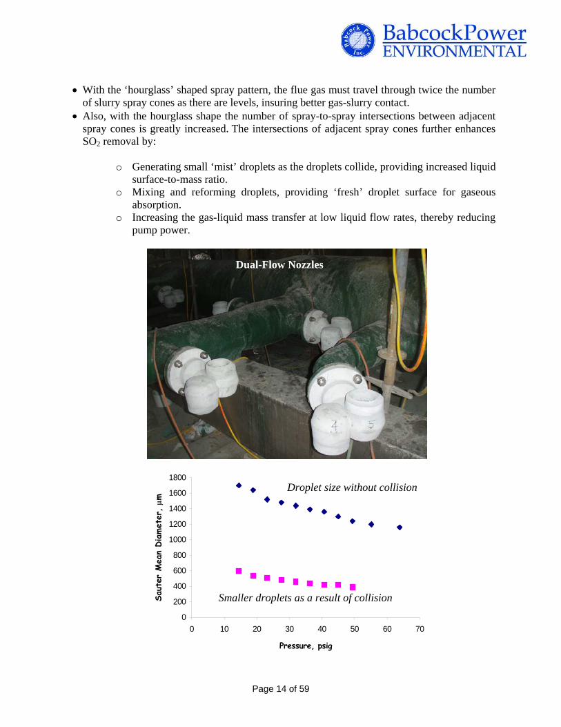
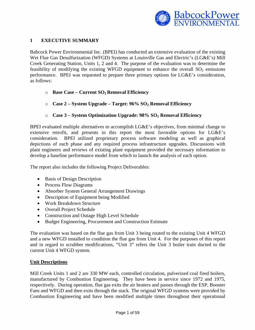
With the ‘hourglass’ shaped spray pattern, the flue gas must travel through twice the number of slurry spray cones as there are levels, insuring better gas-slurry contact.
Also, with the hourglass shape the number of spray-to-spray intersections between adjacent spray cones is greatly increased. The intersections of adjacent spray cones further enhances SO2 removal by:
o Generating small ‘mist’ droplets as the droplets collide, providing increased liquid surface-to-mass ratio.
o Mixing and reforming droplets, providing ‘fresh’ droplet surface for gaseous absorption.
o Increasing the gas-liquid mass transfer at low liquid flow rates, thereby reducing pump power.
Dual-Flow Nozzles
0
200
400
600
800
1000
1200
1400
1600
1800
0 10 20 30 40 50 60
Pressure, psig
Saut
er M
ean
Diamet
er, m
Droplet size without collision
Smaller droplets as a result of collision
70
Page 14 of 59
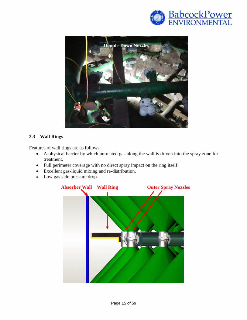
Double-Down Nozzles
2.3 Wall Rings
Features of wall rings are as follows:
A physical barrier by which untreated gas along the wall is driven into the spray zone for treatment.
Full perimeter coverage with no direct spray impact on the ring itself. Excellent gas-liquid mixing and re-distribution. Low gas side pressure drop.
Outer Spray Nozzles Wall Ring Absorber Wall
Page 15 of 59

Wall Rings Installed at Ghent
2.4 Agitators and Oxidation Air System
Side mounted agitators are designed to provide complete dispersion of air and suspension of solids. In order to provide high reliability, these systems are designed such that any one of the agitators can be off-line for maintenance while the absorber remains online for operation. The agitator seal between the rotating shaft and the absorber wall can be replaced with the tank full of slurry, thereby providing additional flexibility and minimal need to drain the tank.
The oxidation air system piping delivers air to each agitator. The agitator slurry flow is towards the center of the tank, slightly off radial and slightly downward. The moving slurry ‘sweeps’ the
Page 16 of 59

floor and provides ‘off bottom suspension’; i.e., no accumulation of solids on the tank floor. The slurry reaches the center of the tank in a slightly off radial direction and turns upward in a helical pattern to the slurry surface. It then travels radially outward, turns down at the tank wall and returns to the agitators. This is a long and useful travel path, providing good mixing and a long time for all the chemical reactions to reach completion. Each agitator is equipped with an oxidation air injection lance. The air exits the end of this lance in the fast moving slurry at the ‘backwash’ of the agitator. This causes the air to be striped into small bubbles, which follow the slurry flow path. This path, as described above, is long and allows time for the oxygen to be absorbed into the slurry. 2.5 Mist Eliminators DV210 Mist Eliminators (shown in the photo below) are an alternative to traditional flat mist eliminator arrangements. The installation of a single layer benefits installation time and requires only one layer of support beams instead of two. The other advantages of DV210 Mist Eliminators are:
Minimal pressure loss Good elimination performance at medium velocities Suitable for retrofit with existing washers Provides a higher net face area than any other design
Mist Eliminator System
Page 17 of 59

2.6 Recycle Pumps BPEI works with all the major recycle pump suppliers to provide the best fit in terms of:
Application, Reliability Power requirements Maintenance Noise Cost Delivery
The predominant difference between the major suppliers is the design of wetted elements. Weir pumps have a replaceable natural rubber liner insert with a high chrome iron impeller and throat bushing. The liner is a robust fitted insert that is specifically designed and formulated for WFGD slurry service. Duchting pumps have an iron shell with a cast-in-place liner and impeller made of a composite of silicon carbide grains with an epoxy binder. The GIW pumps are designed with high chrome iron for all wetted surfaces. Each project requires are thorough evaluation of the recycle pump vendors to determine the best fit in the specific application.
High-Volume Direct-Drive Recycle Pumps
Page 18 of 59

3 BASE CASE - Current SO2 Removal Efficiency 3.1 Technical Summary – Base Case A thorough understanding of current plant operational characteristics and an accurate baseline model are required to complete a performance enhancement study for the Mill Creek WFGD systems. BPEI modeled the existing absorber systems on Mill Creek Units 1, 2, and 3 (Unit 3 flue gas to be redirected to existing Unit 4 WFGD system) using proprietary software and data obtained from plant personnel to create a realistic baseline performance model. BPEI analyzed performance of the model, altering key variables such as flue gas flow, coal sulfur content, recycle pump flow and pressure, recycle spray nozzle type, nozzle spray angles, nozzle coverage, etc. to determine what modifications to the existing systems would provide the most economical reliable performance enhancements for each system. The base model also provides critical feedback to the design engineers to confirm that theories and calculations used in the model are accurate and appropriate as a starting point for performance enhancement using BPEI’s proven techniques.
Absorber Tower “B”Absorber Tower “A”
Existing WFGD Reactor Towers
and Internals (See Fig. 2)
Inlet Ductwork
ID Fan Reaction
Tank
Figure 1: Mill Creek Units 1 & 2, Current
Page 19 of 59

Mist Eliminator Levels 1 & 2
Abandoned Reheater Section
Perforated plate installed between spray level 1 and 2
6’
As-installed, 4 spray levels, down only spray nozzles
4’
5’
Flue Gas Inlet
Figure 2: Mill Creek Units 1 & 2, Current Reactor Tower Arrangement
Page 20 of 59

3.2 System Description Flue gas production is directed by means of two ID fans in parallel feeding the unit A and B absorbers. The absorbers share a single reaction tank. Eight recycle pumps four feeding each absorber provide the total slurry from the tank to the absorbers. Oxidation air is introduced thru a sparger type system. The sparger is arranged as a single header located above the floor introducing air evenly throughout the absorber. Flue gas vertically moves through each of the four spray headers. Above the first spray header LG&E has installed a perforated plate or tray for the purpose of providing even flue gas distribution. The flue gas exits the absorbers through the mist eliminators to the stack.
Figure 3: Mill Creek Units 1 & 2
Page 21 of 59

3.3 Current Process Operation Discussions held with onsite engineers and operators as well as reviews of historical data were used to better understand current operation of the three absorber units. On average the units burn a coal with sulfur content of 5.4 lb SO2/MBtu. Limestone used in the WFGD process to neutralize SO2 is finely ground to 95% passing 325 mesh. The absorbers reliably maintain 90-92% SO2 removal by maintaining an absorber slurry pH in the reaction tank of 5.7-5.8. Absorber slurry solids is maintained between 10-12 wt% and controlled with a bleed system. An oxidation air sparger ring is designed to oxidize the SO2 removed from the flue gas and maintain agitation in the reaction tank. The level in the absorber reaction tanks are controlled at lower set points compared to original design conditions. The absorber slurry solid concentration is also controlled at a lower density than is typical for limestone, forced-oxidation wet FGD systems. Reported unreliability of the absorber bleed system to maintain absorber slurry density resulted in the reduced density control range. It may also be problematic to maintain absorber slurry solids concentration because of the lack of agitation in the absorber reaction tank. Currently the only mixing in the reaction tank is an air sparger ring which has been reported to plug up whenever an oxidation air blower trips out of service and slowly plug up over time with regular operation. The air sparger ring assembly appears to be the highest cause of unreliability in the scrubber process operation. Operating at reduced absorber slurry density and absorber levels reduces the liquids and solids retention time in the absorber reaction tank, which may have the following consequences:
Negative impact on the gypsum quality - smaller crystal size impacting dewatering operations
Increase the amount of excess limestone required for SO2 removal - higher pHs required to maintain SO2 removal efficiency
Reduced Hydrocyclone performance – decreased solids in the underflow to the dewatering process and increased fraction of gypsum fines removed in the overflow purge stream
Flue gas off-gassing between the absorber module and the absorber reaction tank causing area corrosion issues - no seal is maintained
3.4 Spray Header Arrangement / Spray Nozzle Coverage
The high-flow, hollow-cone spray nozzles currently installed in the absorber are designed to produce small droplets with a high spray pressure of 20 psig at a spray angle of 80o on Units 1 and 2 and a spray pressure of 10 psig at a spray angle of 120o on Unit 3. Figure 5 shows the spray coverage with the existing spray header and nozzle configuration. As can be seen there is very little spray coverage along the absorber wall and between the absorber nozzles. The four spray headers are identical in layout such that some channeling of the flue gas through the absorber is likely to occur.
Page 22 of 59
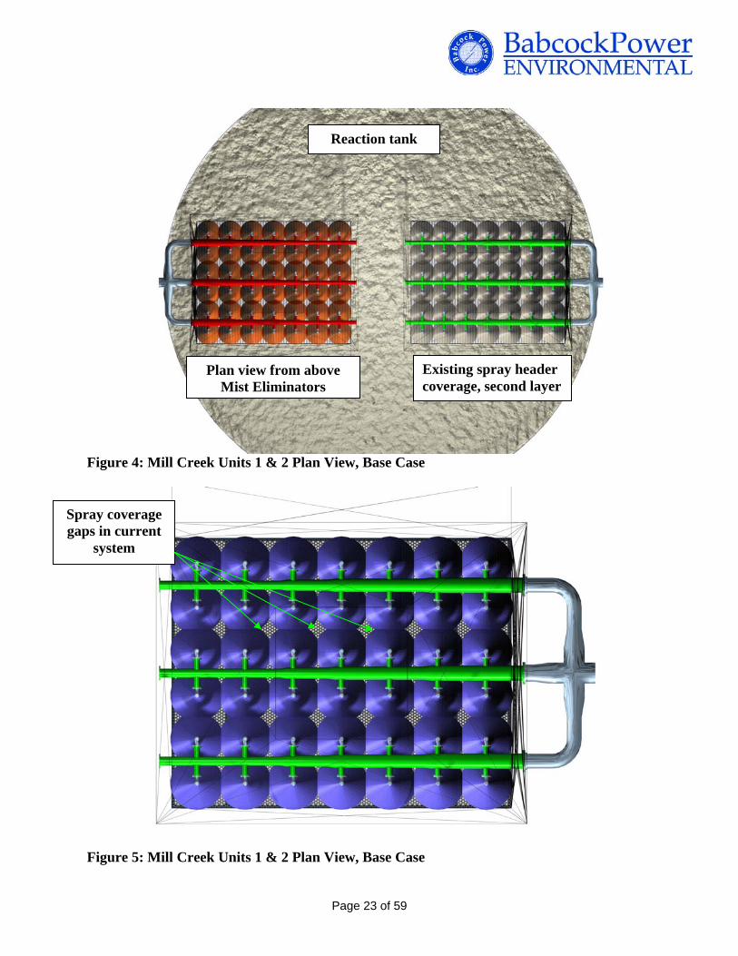
Reaction tank
Existing spray header coverage, second layer
Plan view from above Mist Eliminators
Figure 4: Mill Creek Units 1 & 2 Plan View, Base Case
Spray coverage gaps in current
system
Figure 5: Mill Creek Units 1 & 2 Plan View, Base Case
Page 23 of 59

BPEI recommends testing the spray nozzle performance of each nozzle type to fully understand the current nozzle performance. This is especially critical for Units 1 and 2 because understanding the improvement in performance between current operation and Case 2 might make the difference between utilizing the existing recycle pumps or replacing the recycle pumps. This is covered in more detail in Section 4.
3.5 Recycle Pump Performance
A generic pump curve was provided for the recycle pumps installed on Units 1 and 2 absorbers. Nozzle data was provided regarding the total number of spray nozzles, nozzle flow rate, spray angle, and spray pressure. The recycle pump total dynamic head (TDH) does not correspond to a spray pressure of 20 psig when recycle pumps and piping were modeled. Instead the spray pressure appears to correspond closer to 10 psig spray nozzles. At the lower supply pressure the nozzle performance in terms of spray angle and droplet size and flow rate will not be at design. Conservative assumptions will have to be made regarding the current pump performance and change in pump performance when changing spray header elevations. Pump curves were provided for the recycle pumps installed on the future Unit 3 absorbers (currently absorber is treating Unit 4 flue gas) and nozzle data corresponds to the pump performance. BPEI recommends testing recycle pump performance on all three units to fully understand current pump performance. The pump performance testing would be similar to what was conducted at Trimble County in terms of measuring motor amperage, pump rpm, pump flow rates, and pressure at each pump suction and discharge to locate the actual operating point on the pump curve. The data will be used to evaluate the possibility of utilizing the current recycle pumps with dual spray nozzles for high SO2 removal and determining if new gear boxes on Unit 3 recycle pumps will be appropriate for maximum SO2 removal.
3.6 Absorber Inlet Design
On all units the absorber flue gas inlet is shorter and has a larger surface area than typical for new absorber designs. The length of the absorber inlet is designed to minimize splash back of absorber slurry into the carbon steel ductwork. Flue gas velocity in the absorber is controlled with the size of the absorber inlet to evenly distribute flue gas prior to the first spray level, to eliminate any reverse flow in the duct, and to maintain the wet/dry interface in the absorber area. Otherwise, a large, shallow absorber inlet may result in corrosion of the ductwork upstream of the absorber. Computational flow modeling will determine if the installed tray offsets the negative impact of the current absorber inlet design or if modifications are required to the absorber inlet. Physical flow modeling is recommended at a minimum for Unit 3 since ductwork would need to be re-routed to Unit 4 absorbers. Turning vanes, a perforated plate, and modifications to the inlet duct at Trimble County are an example of how to optimize flue gas flow through the absorber and eliminate the potential for
Page 24 of 59

reverse flow into the ductwork. Figure 6 shows some of the modifications completed to Trimble County absorber inlet. These modifications were completed based on CFD modeling.
Original scrubber inlet duct shown in red. Modifications for improved gas flow shown in green.
Elevation view of inlet duct modifications Plan view of inlet duct
modifications
Figure 6: Inlet Ductwork Modifications at LG&E Trimble County
3.7 Design Basis
Table 2 provides a summary of coal analyses for the Mill Creek Station. The first set of data is a summary of the average fuel burned at Mill Creek in 2009. On average Mill Creek burned a coal with an inlet SO2 concentration of 5.4 lb/MBtu based on the average coal sulfur content and high heating value. The specified fuel for this study is a design coal similar to what was used for Ghent Station Units 1,3 & 4 and Brown Station WFGD Systems with an inlet SO2 concentration of 6.3 lb/MBtu and heating value of 12,500 Btu’s/lb used to evaluate current absorber performance and absorber performance for Cases 2 and 3. The higher sulfur content is designed to represent future operation at Mill Creek Station.
Page 25 of 59
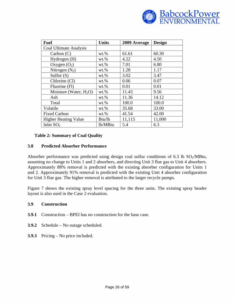
Fuel Units 2009 Average Design Coal Ultimate Analysis Carbon (C) wt.% 61.61 60.30 Hydrogen (H) wt.% 4.22 4.50 Oxygen (O2) wt.% 7.01 6.80 Nitrogen (N2) wt.% 1.28 1.17 Sulfur (S) wt.% 3.02 3.47 Chlorine (Cl) wt.% 0.06 0.07 Fluorine (Fl) wt.% 0.01 0.01 Moisture (Water, H2O) wt.% 11.43 9.56 Ash wt.% 11.36 14.12 Total wt.% 100.0 100.0 Volatile wt.% 35.68 33.00 Fixed Carbon wt.% 41.54 42.00 Higher Heating Value Btu/lb 11,115 11,000 Inlet SO2 lb/MBtu 5.4 6.3
Table 2: Summary of Coal Quality
3.8 Predicted Absorber Performance Absorber performance was predicted using design coal sulfur conditions of 6.3 lb SO2/MBtu, assuming no change to Units 1 and 2 absorbers, and directing Unit 3 flue gas to Unit 4 absorbers. Approximately 88% removal is predicted with the existing absorber configuration for Units 1 and 2. Approximately 91% removal is predicted with the existing Unit 4 absorber configuration for Unit 3 flue gas. The higher removal is attributed to the larger recycle pumps. Figure 7 shows the existing spray level spacing for the three units. The existing spray header layout is also used in the Case 2 evaluation.
3.9 Construction
3.9.1 Construction – BPEI has no construction for the base case. 3.9.2 Schedule – No outage scheduled. 3.9.3 Pricing – No price included.
Page 26 of 59
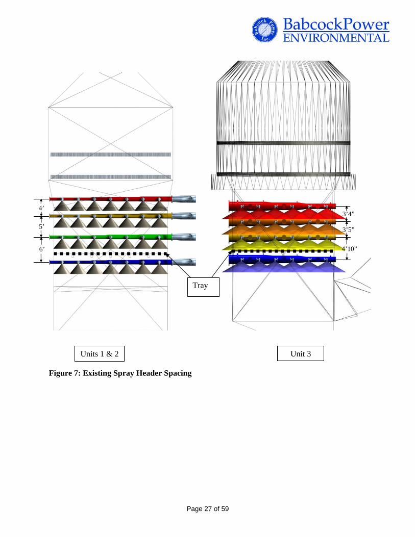
4’ 3’4”
5’ 3’5”
4’10”
Tray
6’
Unit 3 Units 1 & 2 Figure 7: Existing Spray Header Spacing
Page 27 of 59

4 CASE 2 - 96% SO2 Removal Efficiency 4.1 Technical Summary – Case 2
In this section of the report, BPEI’s task objective was to provide to LG&E the most economical, reliable method to obtain 96% SO2 removal for Mill Creek Units 1, 2 and 3. The process models were taken from the baseline condition and modified using a variety of techniques in several stages. Multiple variables were adjusted by application of BPEI’s experience in WFGD and experimental results from the process model. Nozzle spray angle, type, pressure, flow, and arrangement were fine-tuned to provide optimum spray coverage and droplet distribution while maintaining droplet size for peak liquid to gas interaction. Addition of wall rings, a BPEI licensed and patented technology, was evaluated to improve flue gas distribution and prevent laning of gas along the perimeter of the vessels. Changes to the Liquid-to-Gas (L/G) ratio were evaluated via changes in recycle pump flow, pressure, and nozzle flow. Generally L/G ratio trends with removal rate, therefore increasing the flow through the recycle pumps and nozzles corresponds to greater SO2 removal. Several chemical and reaction rate modifications were analyzed, namely liquids residence time and solids residence time. Optimum values for each of these reaction rate parameters have been worked into the existing scrubber operation by revising current ranges for operational level in the reaction tanks, absorber slurry solids ranges, and limestone grind fineness. Finally the forced oxidation system was evaluated with emphasis on achieving superior mixing of injected oxidation air, suspension of slurry in the vessel, and complete oxidation of SO2 removed by the absorber. A summary of the planned modifications respective to each vessel is shown on Table 1.
Page 28 of 59
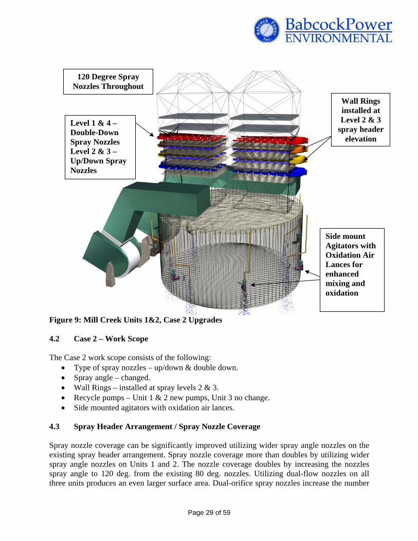
120 Degree Spray Nozzles Throughout
Wall Rings installed at Level 2 & 3
spray header elevation
Side mount Agitators with Oxidation Air Lances for enhanced mixing and oxidation
Level 1 & 4 – Double-Down Spray Nozzles Level 2 & 3 – Up/Down Spray Nozzles
Figure 9: Mill Creek Units 1&2, Case 2 Upgrades
4.2 Case 2 – Work Scope
The Case 2 work scope consists of the following: Type of spray nozzles – up/down & double down. Spray angle – changed. Wall Rings – installed at spray levels 2 & 3. Recycle pumps – Unit 1 & 2 new pumps, Unit 3 no change. Side mounted agitators with oxidation air lances.
4.3 Spray Header Arrangement / Spray Nozzle Coverage
Spray nozzle coverage can be significantly improved utilizing wider spray angle nozzles on the existing spray header arrangement. Spray nozzle coverage more than doubles by utilizing wider spray angle nozzles on Units 1 and 2. The nozzle coverage doubles by increasing the nozzles spray angle to 120 deg. from the existing 80 deg. nozzles. Utilizing dual-flow nozzles on all three units produces an even larger surface area. Dual-orifice spray nozzles increase the number
Page 29 of 59

of droplets and the number of droplet collisions. Increasing the number of droplet collisions results in smaller droplets and a significant improvement in SO2 removal efficiency because the area available for SO2 absorption has been increased. Spray level 1 will utilize double-downward nozzles since this spray header is located just below the tray. Dual direction nozzles proposed for spray levels 2 and 3 also have additional benefit of increasing the number of collisions and increasing the residence time of droplets in the absorber. Spray level 4 utilizes double-downward nozzles to minimize carryover into the mist eliminator section. Figure 10 is example of a bi-directional spray nozzle being tested. BPEI proposes increasing the spray angle from 80o to 120o on Units 1 and 2. Figures 11, 12, and 13 show the additional coverage achieved with the dual flow nozzles.
Figure 10: Bi-directional spray nozzle testing
Page 30 of 59

Figure 11: Mill Creek Units 1 & 2, Case 2 Elevation View
Dual flow nozzles installed on levels 2 & 3
Original header and perforated
tray
Mist Eliminators
Wall Rings installed at levels
2 and 3
Double-down spray nozzles installed on
level 1
Double-down spray nozzles installed on
level 4
Flue Gas Inlet Duct
Page 31 of 59
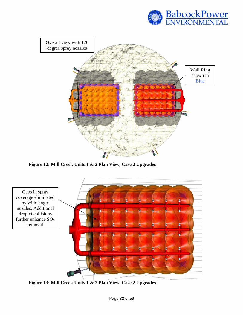
Overall view with 120 degree spray nozzles
Figure 12: Mill Creek Units 1 & 2 Plan View, Case 2 Upgrades
Gaps in spray coverage eliminated
by wide-angle nozzles. Additional droplet collisions
further enhance SO2 removal
Wall Ring shown in
Blue
Figure 13: Mill Creek Units 1 & 2 Plan View, Case 2 Upgrades
Page 32 of 59

120 Degree nozzles, double down on
levels 1 & 4, dual flow on levels 2 & 3
Spray Headers
Absorber Agitators and Oxidation Air Lances
Figure 14: Mill Creek Units 1 & 2 Elevation View, Case 2 Upgrades
4.4 Wall Rings
There is a physical limit to the degree of spray coverage along the wall of the absorbers especially in the corners of square reactor modules. Increased flue gas flow is expected along the wall because of the decreased resistance from this reduced coverage. BPEI will add wall rings to deflect flue gas from the absorber wall into the interior of the absorber where there is a greater chance of interaction with recycle spray droplets. This also promotes more thorough mixing of the flue gas, ensuring no areas of high SO2 concentration along the walls are allowed to bypass the effective spray zones. Figure 15 below shows a typical wall ring installation in a circular, tile-lined vessel.
Page 33 of 59

Typical wall ring arrangement (circular vessel shown)
Recycle spray nozzle
Flue gas is forced away from the vessel wall, back towards the interior where it is more likely to have liquid to gas interaction, increasing SO2 removal efficiency Recycle Spray Header
and vessel flange
Figure 15: Typical Wall Ring Arrangement (Ghent Plant)
Wall rings will be added at spray levels 2 and 3 to maximize the benefit of contacting flue gas with the slurry spray while minimizing the impact on pressure drop across the absorber. Preliminarily, the pressure drop increase is expected to be minimal. Figure(s) 16 is a graphic representation of the wall rings proposed for Mill Creek absorbers.
Wall Ring: typically corrosion resistant alloy construction
Figure 16: Proposed Wall Ring, typical arrangement
Page 34 of 59

Dual-flow nozzles installed on levels 2 & 3
Original header and perforated
tray
Wall Rings installed at levels
2 and 3
Mist Eliminators
Double-down spray nozzles
installed on levels 1 & 4
Figure 17: Mill Creek Unit 3 Elevation View, Case 2 Upgrades 4.5 Liquid-to-Gas Ratio The Liquid-to-Gas Ratio (L/G) is a sizing criteria for absorbers that compares the slurry recirculation rate to the flue gas flow rate. Presently the L/G ratio for Units 1 and 2 is estimated to fall between 112 gal/kacf and 129 gal/kacf based on available recycle pump data. The L/G of 112 gal/kacf assumes a design flue gas flow rate based on Ghent and Brown flue gas flow rates and scaled down for Mill Creek Units 1 and 2. This flue gas flow rate results in a gas velocity through the absorber of 15.5 ft/sec which is close to what plant personal reported for these units. The higher L/G ratio of 129 gal/kacf is calculated when the original absorber design flue gas flow rates are modeled. The reduced flue gas flow rate results in a reduced flue gas velocity of 13.3 ft/sec through the absorber. For the purpose of this study, the worst-case high flue gas flow rates/reduced L/G ratios were used to evaluate improvements to these units.
Page 35 of 59

The L/G ratio for Unit 3 is 153 gal/kacf. There is more data available for Unit 3 flue gas flow rates as a result of baseline testing completed on Unit 3. Unit 4 absorber cross-sectional area is approximately 23% greater than the original Unit 3 absorbers and as a result the flue gas velocity is reduced compared to Units 1 and 2 at 10.8 ft/sec (versus the original flue gas velocity of 13.4 ft/sec through the existing Unit 3 absorbers). The higher L/G is also a result of the higher recycle pump flow rates for the current Unit 4/future Unit 3 absorber. The design basis for the flue gas is summarized in Appendix Basis of Design Description. The units were modeled with the dual spray nozzles and wall rings installed. Unit 3 is expected to achieve 96% removal provided other process issues are addressed as discussed in the following sections. Units 1 and 2 will require a higher L/G ratio of 141 gal/kacf to achieve 96% removal. The higher L/G ratio is equivalent to a pump flow rate of 19,000 gpm requiring new recycle pumps to be able to achieve 96% removal. The slurry velocity through the recycle piping for Units 1 and 2 is already 50% higher than what BPEI would recommend to minimize erosion issues. Utilizing higher flow pumps would also require replacing the recycle piping, pump isolation valves, and larger spray headers. The higher pump flow rate will also increase the pressure drop across the absorber and impact ID fan performance. This is why a thorough understanding of the existing recycle pump and spray nozzle performance through physical testing is required to determine if this is necessary.
In addition, more cost effective options are available as an alternative to replacing recycle pumps to achieve 96% SO2 removal on Units 1 and 2. Alternative options include utilizing limestone slurry with a finer grind and the addition of organic acid to these absorbers. Either of these options will increase SO2 removal efficiency without a negative impact on current absorber layout and ID fan performance. The absorber design is not very far off from making the 96% removal mark based on current absorber performance. While replacing recycle pumps may be desirable to achieve maximum removal efficiency with these absorbers. BPEI recommends maximizing SO2 removal in Unit 1 and 2 absorbers with modifications of dual-flow nozzles and wall rings and then making process changes if necessary to achieve 96% SO2 removal.
4.6 Absorber Solids/Liquid Residence Time As previously mentioned the WFGD systems at Mill Creek are normally operated at reduced slurry solids concentration and reduced reaction tank levels compared to original design set points. These operating conditions coupled with higher inlet SO2 concentrations and higher SO2 removals to be considered for this retrofit reduces the solids and liquid residence time in the absorbers. New limestone, forced-oxidized absorber systems are traditionally designed to maintain a solids residence time of 15 hours and a liquid residence time of 5 minutes. Solids residence time is necessary to provide adequate time in the reaction tank for gypsum crystal growth. The purpose of liquid residence time is to minimize the amount of excess limestone required to maintain SO2 removal by allowing adequate time for the limestone to dissolve. This is especially important in the production of wallboard grade gypsum. Five minutes is standard liquid residence time for the limestone grind fineness and the limestone reactivity typical of limestone used at Mill Creek. In retrofit projects BPEI tries to maintain at minimum 12 hours solids residence time and 4.5 minutes liquid residence time. The absorber trays are designed to
Page 36 of 59

add to the liquid residence time because of slurry holdup on the tray itself. However, BPEI does not have data available to evaluate the benefit of the tray on liquid residence time.
Unit 1 and 2 reaction tanks are appropriately sized. At the reduced solids density and reduced tank levels the solids residence time is 15.1 hours and the liquid residence time 7.0 minutes. At minimum BPEI recommends increasing the reaction tank level set point from 31.5’ to the original design level of 35.5’ to maintain a liquid seal between the absorber modules and the reaction tanks and eliminate the potential for flue gas corrosion above the reaction tank. There are several other areas in inlet and outlet ductwork where flue gas leakage is occurring. The corrosion and gas leakage issues are not discussed in this report. Unit 3 reaction tanks are very small and were originally designed for a lime-slurry, natural-oxidation process. Lime slurry has a faster dissolution rate compared to limestone slurry so reaction tanks are normally designed with reduced liquid residence times. Also, higher solids residence times did not improve the dewatering properties of calcium sulfite hemi-hydrate crystals. Even though Unit 3 is a larger unit compared to Units 1 or 2 (425 MW vs 330 MW), the total reaction tank volume is 25% less than Units 1 and 2 reaction tank volumes. At the reduced solids density and reduced tank levels the solids residence time is 8.3 hours and the liquid residence time 3.2 minutes. BPEI recommends increasing the reaction tank level set point from 15’ to original design level of 18’ to increase these residence times and to maintain a liquid seal between the absorber modules and the reaction tanks. BPEI also recommends improving the reliability of the absorber bleed system so that absorber slurry density can be maintained within controlled limits. Improving the reliability of the bleed system requires an evaluation of the bleed control valves and bleed logic. Brown has a similar bleed system design as Mill Creek with a Hydrocyclone assembly installed at the absorber. This system operates with high reliability and BPEI believes the reliability of the bleed system at Mill Creek can be improved to maintain a solids concentration approximately 15 wt%, which is typical of limestone forced-oxidation systems. Increasing the reaction tank level and absorber slurry solids increases the solids residence time to 13.8 hours and the liquid residence time to 3.8 minutes.
The liquid residence time is still below minimum recommendations for this process. The negative impact is increased excess limestone required (higher absorber slurry pH) to maintain SO2 removal. The absorber tray may eliminate this issue however alternatives to increasing liquid residence time were evaluated. One way to increase liquid residence time is to increase the volume of the reaction tanks. This is a less desirable solution and would require changing the geometry of the transition from absorber to the reaction tank and increasing the level of the reaction tank. Additionally, liquid residence time can be increased by reducing recycle pump flow to 25,000 gpm. As a result SO2 removal will be close but may not necessarily be maintained at 96%. Reducing pump flow rates will also require modifications to the recycle pump impellers. Alternatively, limestone grind fineness can be increased to offset the decreased liquid residence time. This option will be discussed in more detail in Section 5 of this report.
Page 37 of 59
4.7 Oxidation Air Blowers and Agitators
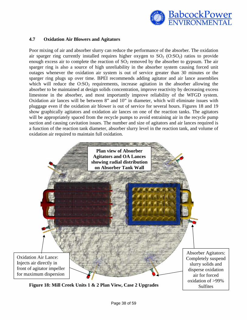
Poor mixing of air and absorber slurry can reduce the performance of the absorber. The oxidation air sparger ring currently installed requires higher oxygen to SO2 (O:SO2) ratios to provide enough excess air to complete the reaction of SO2 removed by the absorber to gypsum. The air sparger ring is also a source of high unreliability in the absorber system causing forced unit outages whenever the oxidation air system is out of service greater than 30 minutes or the sparger ring plugs up over time. BPEI recommends adding agitator and air lance assemblies which will reduce the O:SO2 requirements, increase agitation in the absorber allowing the absorber to be maintained at design solids concentration, improve reactivity by decreasing excess limestone in the absorber, and most importantly improve reliability of the WFGD system. Oxidation air lances will be between 8” and 10” in diameter, which will eliminate issues with pluggage even if the oxidation air blower is out of service for several hours. Figures 18 and 19 show graphically agitators and oxidation air lances on one of the reaction tanks. The agitators will be appropriately spaced from the recycle pumps to avoid entraining air in the recycle pump suction and causing cavitation issues. The number and size of agitators and air lances required is a function of the reaction tank diameter, absorber slurry level in the reaction tank, and volume of oxidation air required to maintain full oxidation.
Plan view of Absorber Agitators and OA Lances
showing radial distribution on Absorber Tank Wall
Figure 18: Mill Creek Units 1 & 2 Plan View, Case 2 Upgrades
Absorber Agitators: Completely suspend
slurry solids and disperse oxidation
air for forced oxidation of >99%
Sulfites
Oxidation Air Lance: Injects air directly in front of agitator impeller for maximum dispersion
Page 38 of 59

Agitator Mechanical Seal, Vessel Penetration
Side Mounted Absorber Agitator Oxidation Air Injection
Lances (One paired with each agitator)
Figure 19: Absorber Agitator/Lance
Oxidation air rates required for the high sulfur, high SO2 removal on Units 1 and 2 is 10,300 scfm with a supply pressure of 14.6 psig per unit. At present conditions the oxidation air blowers run at minimum levels to maintain the airflow necessary for high oxidation. Oxidation air is provided to Units 1 and 2 with a common blower. Based on present blower operation and the air compressor size (Atlas Copco HA10) it is believed the existing blowers can be used with the new agitator/lance design. The oxidation air rate required for Unit 3 is 14,000 scfm with a supply pressure of 7.2 psig. Unit 3 oxidation air is provided by a dedicated blower. The existing air compressor is capable of maintaining adequate airflow for Unit 3 with the blower operating at minimum load. However, with the relatively short reaction tank levels the blower discharge pressure is relatively low. The piping system may require an orifice to keep the air compressor operating on its curve.
Page 39 of 59
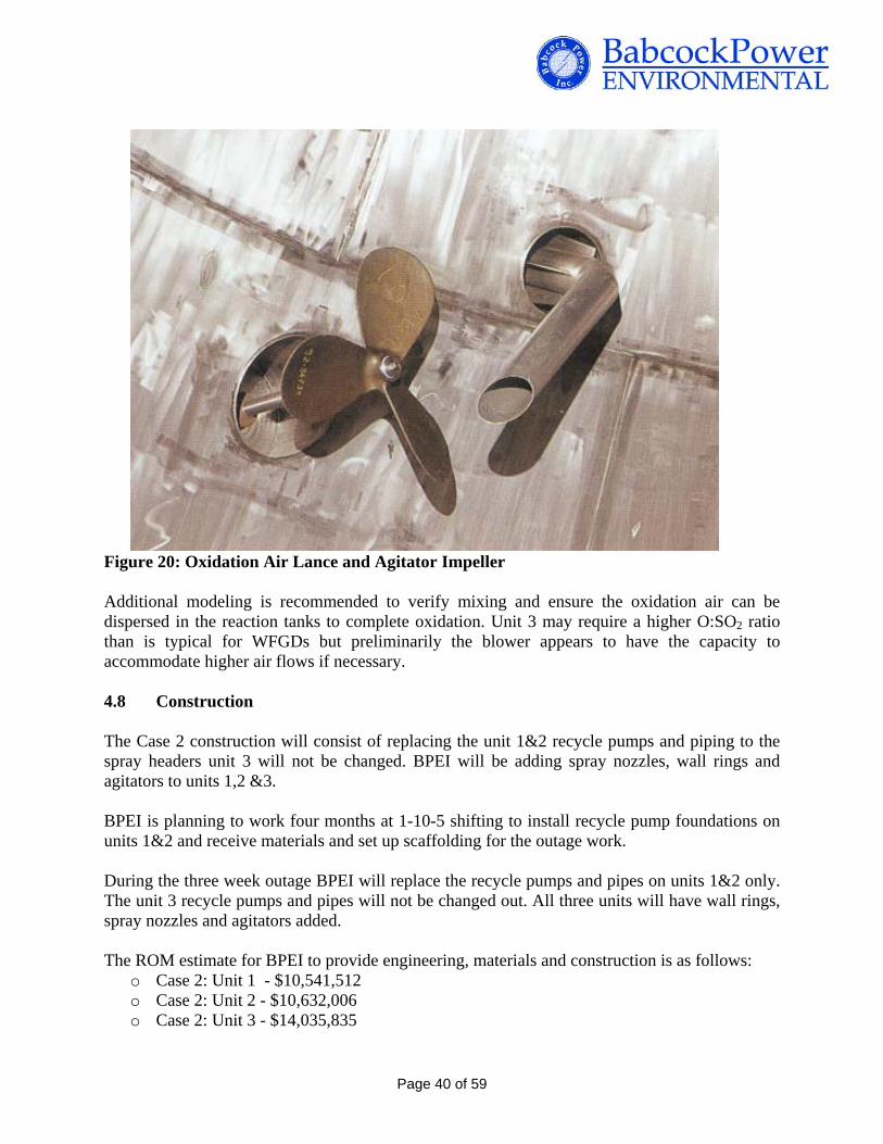
Figure 20: Oxidation Air Lance and Agitator Impeller Additional modeling is recommended to verify mixing and ensure the oxidation air can be dispersed in the reaction tanks to complete oxidation. Unit 3 may require a higher O:SO2 ratio than is typical for WFGDs but preliminarily the blower appears to have the capacity to accommodate higher air flows if necessary.
4.8 Construction
The Case 2 construction will consist of replacing the unit 1&2 recycle pumps and piping to the spray headers unit 3 will not be changed. BPEI will be adding spray nozzles, wall rings and agitators to units 1,2 &3. BPEI is planning to work four months at 1-10-5 shifting to install recycle pump foundations on units 1&2 and receive materials and set up scaffolding for the outage work. During the three week outage BPEI will replace the recycle pumps and pipes on units 1&2 only. The unit 3 recycle pumps and pipes will not be changed out. All three units will have wall rings, spray nozzles and agitators added. The ROM estimate for BPEI to provide engineering, materials and construction is as follows:
o Case 2: Unit 1 - $10,541,512 o Case 2: Unit 2 - $10,632,006 o Case 2: Unit 3 - $14,035,835
Page 40 of 59

4.9 Schedule
Our preliminary schedule included in the attachments section is based on the following:
Case 2: Units 1, 2, & 3:4
- (4) Month construction schedule working (1-10-5) One shift, ten hours per day for five days
- (3) week outage schedule working (2-10-6) Two shifts, ten hours per shift, six days per week
Page 41 of 59

5 CASE 3 +98% SO2 Removal Efficiency 5.1 Technical Summary – Case 3
In the final stage of analysis all available methods for performance enhancement are brought into play. Spray header layout and nozzle selection are optimized based on the overall absorber shell dimensions for absolute maximum performance based on the existing reactor tower dimensions. For Units 1 & 2, recycle pumps are pushed further and piping is resized for greater flow to increase L/G significantly over the original and 96% removal option. Unit 3 does not require higher L/G ratio to maximize SO2 removal. Spray header spacing is increased and placement is altered to allow for multiple levels of bidirectional nozzles, which have proven to be superior in performance compared to down-only nozzles. Spray header layout is altered to provide added spray density and prevent any holes in spray coverage by moving the position of individual nozzles on the headers.
5’
5’
5’Perforated Tray
Figure 21: Mill Creek Units 1 and 2, Case 3 Upgrades
Page 42 of 59
Wall Rings installed at
levels 2 and 3
Absorber Inlet Duct
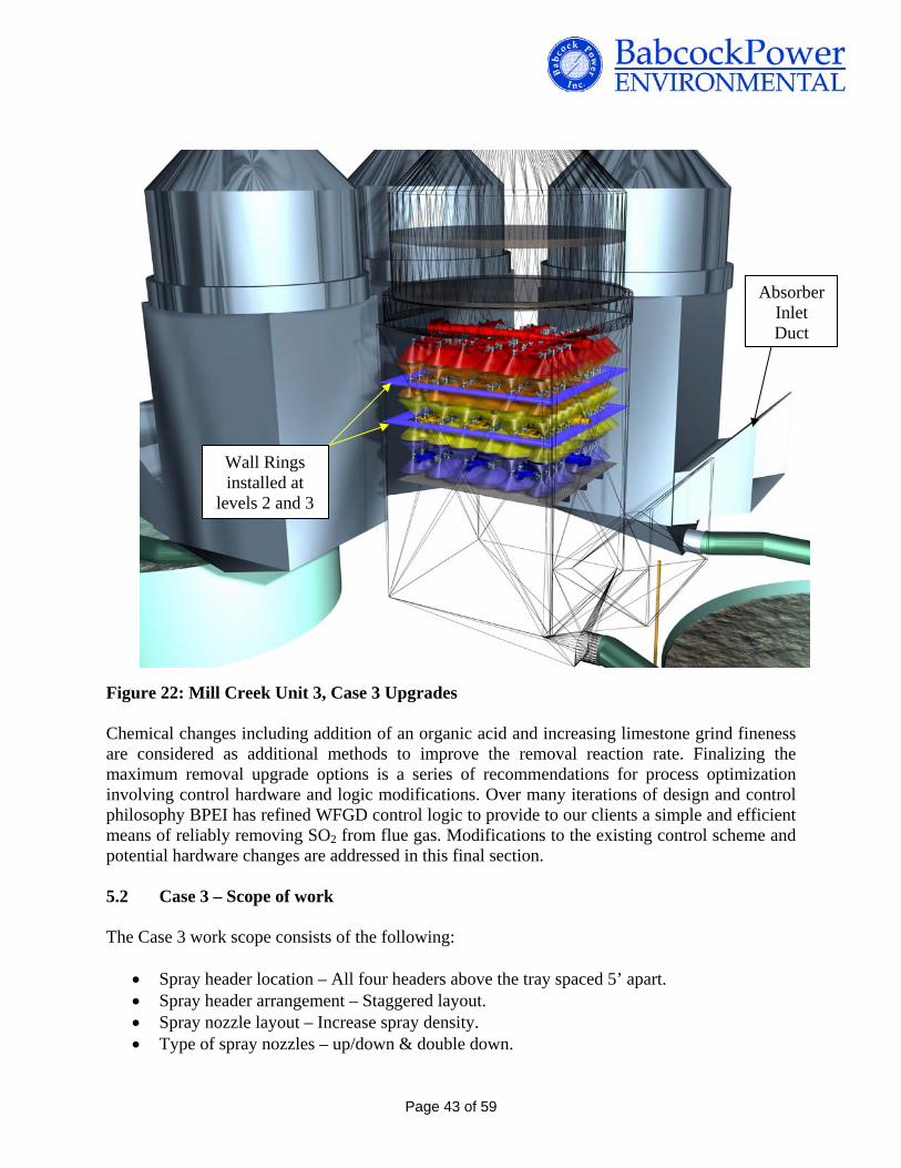
Figure 22: Mill Creek Unit 3, Case 3 Upgrades Chemical changes including addition of an organic acid and increasing limestone grind fineness are considered as additional methods to improve the removal reaction rate. Finalizing the maximum removal upgrade options is a series of recommendations for process optimization involving control hardware and logic modifications. Over many iterations of design and control philosophy BPEI has refined WFGD control logic to provide to our clients a simple and efficient means of reliably removing SO2 from flue gas. Modifications to the existing control scheme and potential hardware changes are addressed in this final section.
5.2 Case 3 – Scope of work The Case 3 work scope consists of the following:
Spray header location – All four headers above the tray spaced 5’ apart. Spray header arrangement – Staggered layout. Spray nozzle layout – Increase spray density. Type of spray nozzles – up/down & double down.
Page 43 of 59

Spray angle – changed. Wall Rings – installed at spray levels 2 & 3. Side mounted agitators with oxidation air lances Recycle pumps – U1&2: new pumps, U3: new gearboxes. Mist eliminator – Install new DV210.
5.3 Optimization of Absorber General Arrangement
The current arrangement of the tray and spray headers is less than optimal for maximum SO2 removal. The spray headers are spaced closely together and the tray is currently installed between spray levels 1 and 2 eliminating the use of dual-flow bi-directional spray nozzles on the first spray level. Additionally, the nozzle arrangement is identical between spray levels which can result in flue gas channeling (“laning”) through the absorber, reducing SO2 removal potential. BPEI proposes the following to maximize SO2 removal efficiency across the absorber:
Relocate bottom spray header above the perforated tray Space the spray levels 5 ft apart Stagger nozzle layout between spray levels Increase spray density
Originally trays were installed in open spray towers with a spray header installed below the tray to quench the flue gas and minimize scaling on the tray. This was especially an issue on natural oxidation systems. Research has since been completed to demonstrate a quench spray header is not necessary for limestone, forced-oxidation systems. BPEI proposes leaving the installed tray in its existing location and rearranging the spray headers so that they are all located above the tray. Relocating the first spray header will also allow the use of dual-flow, bi-directional spray nozzles on an additional spray header.
Spray Header Spacing
The spray headers will be relocated 5 ft apart to match current design practices for high efficiency absorbers.
To create the extra space required in the spray zone section, BPEI proposes removing the abandoned re-heater section and relocating the mist eliminator section in this unused section.
Moving the spray headers in this manner allows the use of bi-directional nozzles on all but the top level spray header. Further, this spray header spacing provides for a providing more uniform distribution of slurry to the entire spray zone with enhanced droplet formation for more intimate contact between SO2 molecules and slurry droplets.
Figures 22 through 26 show the original and proposed spray header spacing for Units 1 and 2 and Unit 3.
Page 44 of 59
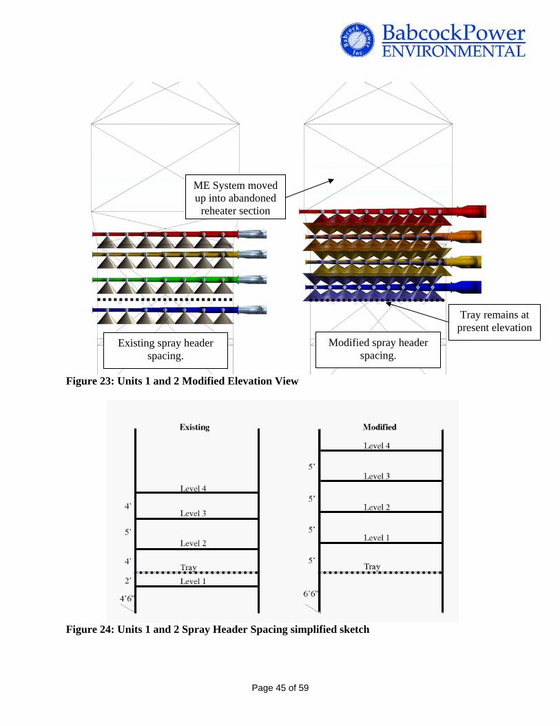
Existing spray header spacing.
Modified spray header spacing.
ME System moved up into abandoned
reheater section
Tray remains at present elevation
Figure 23: Units 1 and 2 Modified Elevation View
Figure 24: Units 1 and 2 Spray Header Spacing simplified sketch
Page 45 of 59

ME System moved up into abandoned
reheater section
Modified spray header spacing.
Existing spray header spacing.
Figure 25: Unit 3 Modified Elevation View
Figure 26: Unit 3 Spray Header Spacing simplified sketch
Page 46 of 59

Staggered Nozzle Layout & Increased Spray Density
Staggering the nozzle layout between spray headers minimizes the potential of gas channeling or ‘laning’ through paths of low liquid flow, i.e. paths of least resistance.
Wall Rings along the full inner perimeter of the vessel counteract the ‘wall effect’ ensuring that the gas flowing upward along the walls is fully treated and reduces the amount of ‘lost’ slurry that is sprayed onto the wall by redirecting that slurry out into the spray zone.
Good liquid distribution over the entire spray level cross-section ensures all flue gas that passes through the absorber is treated.
On smaller absorbers with a standard nozzle layout as Mill Creek the flow rate per nozzle is higher than typical for high efficiency scrubber designs therefore to maintain a small droplet profile with high flow nozzles requires increasing the spray pressure, resulting in a higher TDH for the recycle pumps.
Alternately, increasing the number of spray nozzles per spray header, thus increasing spray density, is the most effective use of the low spray pressure nozzles proposed for the Mill Creek upgrade.
Increasing the spray density has the potential additional benefits of increasing the removal of particulate and acid gas (SO3) in the absorber.
Nozzle placement is now staggered to
provide full coverage of flue gas and
preventing laning.
Wall rings
Figure 27: Unit 3 Modified Spray Header Layout
Page 47 of 59

Plan View
Wall Ring
Nozzle density is increased from 42 per level to 54 per level Elevation View
Nozzle coverage has been modified to provide
maximum overlap in the spray zone.
Down only, dual-flow nozzles on level 4
Wall Rings
Bi-directional nozzles on level 1, 2 and 3
Figure 28: Mill Creek Units 1 & 2 Modified Nozzle Arrangement
Page 48 of 59
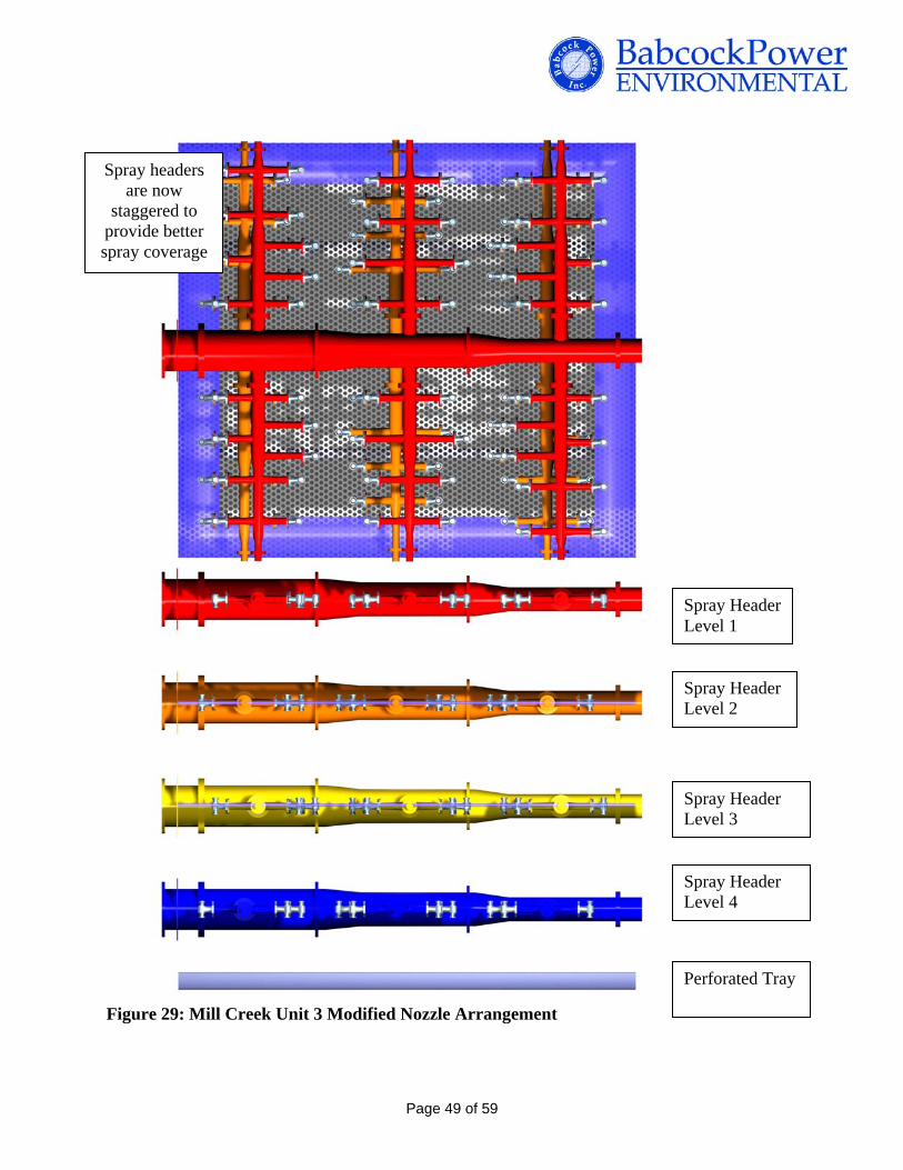
Spray headers are now
staggered to provide better spray coverage
Spray Header Level 1
Spray Header Level 2
Spray Header Level 3
Spray Header Level 4
Perforated Tray Figure 29: Mill Creek Unit 3 Modified Nozzle Arrangement
Page 49 of 59

Figures 30 and 31 are Process Flow Diagrams with the new spray header layout for Units 1 and 2 and Unit 3.
Figure 30: Unit 1 Process Flow Diagram
Page 50 of 59

Figure 31: Unit 3 Process Flow Diagram
Optimization of Absorber Process Conditions The units were modeled with the above referenced spray header arrangement modifications. The recycle pump curves were used to estimate pump performance with the increased TDH (from the higher spray level elevation). Utilizing the existing recycle pumps for Units 1 and 2, the decreased pump flow rate with the new TDH is approximately 12,000 gpm, decreasing the L/G ratio to 89 gal/kacf. SO2 removal efficiency is predicted to drop below 95% with the high sulfur coal. To achieve +98% SO2 removal the existing recycle pumps will have to be replaced with pumps that can achieve 19,400 gpm flow which results in a L/G ratio of 144 gal/kacf. An additional case was considered leaving recycle spray levels 2 through 4 in the present location and only relocating spray header 1 to the top of the absorber area. To achieve 98+% SO2 removal with the overall spray height reduced 2 ft requires increasing the L/G ratio from 144 to 151 gal/kacf.
Page 51 of 59

Utilizing Unit 4 recycle pumps for Unit 3, the decreased pump flow rate with the new TDH is approximately 24,000 gpm (12,000 gpm/header), decreasing the L/G ratio to 134 gal/kacf. High SO2 removal efficiency (>97%) is still predicted for this operating case. However, to maximize SO2 removal potential, BPEI recommends increasing the recycle pump flow to the current rate of 27,500 gpm, returning the L/G ratio to 151 gal/kacf. Preliminary review of the Unit 3 recycle pumps indicates it may be possible to maintain the pump capacity to operate at the higher TDH by utilizing new gear boxes. A liquid residence time of 4.2 minutes is calculated for Unit 3 at this L/G ratio. Options available to address issues with the decreased residence time include using limestone slurry with a finer grind or adding organic acid to the process. These options are discussed in more detail below. The additional liquid residence typically achieved with the use of a tray should be enough to offset the physical limits of the reaction tanks. An additional case was considered leaving recycle spray levels 2 through 4 in the present location and only relocating spray header 1 to the top of the absorber area. The distance between spray headers on Unit 3 absorbers are much shorter (~3.5 ft apart) compared to Units 1 and 2. To achieve 98+% SO2 removal with the overall spray height reduced 6 ft requires increasing the L/G ratio from 151 to 174 gal/kacf. It may be possible to still utilize the recycle pumps utilizing new gear boxes and possibly impellers, however the higher L/G has a negative impact on liquid residence time. The residence time is reduced to 3.6 minutes which may or may not be offset with the absorber tray and chemical adjustments such as finer ground limestone slurry or the addition of organic acid. The reduced spray height also impacts the benefits of the dual-dual flow nozzles. The overall recycle pump flow rate does not change on Unit 3. The recycle piping is 36” in diameter. The slurry velocity of 8.7 ft/sec is within the limits of 5 to 10 ft/sec recommended by BPEI. When the recycle piping splits between the two absorbers the slurry velocity increases to 9.8 ft/sec. No modifications to the recycle piping is anticipated. The required recycle pump flow rate increases 30% for Units 1 and 2. The recycle piping diameter is 20”. The line velocity with the current recycle pump flow is already high at 15 ft/sec . High slurry velocities will result in increased erosion of the recycle piping especially in piping bends. It is recommended to increase the recycle piping diameter to 30” to bring the slurry velocity down to 9 ft/sec with the higher pump flows. The three branches at each spray level will increase from 14” to 18” to maintain slurry velocity. These modifications also require replacing the recycle pump suction valves and installing new nozzles on the absorber recycle tank for the larger pump suctions. Since recycle piping and headers require modification there is no benefit leaving spray levels 2 through 4 in their present location but proceeding with maintaining the optimal spray header distance of 5 ft between spray headers to maximize SO2 removal. The new pump flow rates will also increase the pressure drop across the absorbers impacting ID fan performance. Based on conversations with plant personal, it is understood that the ID fans are already operating at their maximum capacity and that either new ID fans or booster
Page 52 of 59

fans are planned to accommodate a future SCR and fabric filter for Units 1 and 2. Increase pressure drop across the absorbers to accommodate higher L/G ratios for maximum SO2 removal should be considered in the new fan design. If the planned absorber modifications are to be completed prior to any modifications/additions to the upstream fans there is an alternative option to increase SO2 removal while minimizing the impact of absorber pressure drop. This option requires removal of the absorber tray and increasing the L/G ratio from 144 gal/acf to 172 gal/acf. Further review to understand the pressure drop across the absorber tray versus maintaining a higher L/G ratio would have to be completed prior to following this recommendation. If the tray is removed from the absorber, the first absorber spray level would be located at the elevation of the tray and the subsequent spray levels spaced 5 ft apart from each other. BPEI recommends adding pressure instrumentation on the pump suctions and discharges to monitor pump performance and adding logic to protect the recycle pumps from cavitation if there is a sudden loss of suction pressure. It is also recommended to add control valves to the pump flush water connections and pumps drain to incorporate an automatic flush and drain sequence. The absorber control logic at Mill Creek controls limestone slurry feed by maintaining an absorber reaction tank pH set point. To maintain high SO2 removal efficiency and optimize limestone consumption BPEI recommends going to a feed-forward logic loop with feedback trims to control limestone slurry feed to the reaction tanks. Feed-forward logic, calculates limestone slurry rate based on inlet SO2, an SO2 removal or emissions set point, limestone slurry concentration, and unit load or flue gas flow rate. There are two feedback trims to the calculated limestone slurry feed rate. The first feedback trim looks at the actual SO2 removal or emissions rate and adds more limestone slurry if the unit is under-scrubbing or decreases limestone slurry feed rate if unit is over-scrubbing. The second feedback trim looks at reaction tank pH and will override SO2 trim, if necessary, to maintain the reaction tank pH between 5 and 6. This type of feed-forward logic allows for tighter control because the limestone slurry feed rate is adjusted as inlet conditions (such as unit load) change instead of a system that is reactive and swinging up and down around the set point. BPEI recommends a review of the absorber control logic and to consider using CEMs instrumentation, if abandoned on the old Unit 3 system, to measure inlet SO2 on Units 1 and 2.
5.4 Impact of Reagent Grind Size
The limestone grind maintained at Mill Creek is consistently finer than 95% passing 325 mesh which is the minimum grind BPEI recommends for high SO2 removal efficiency absorbers. Increasing the limestone grind to greater than 99% passing 325 mesh increases the rate the limestone dissolves in the reaction tank. Increasing the rate of limestone dissolution will offset the short liquid residence time in Unit 3 reaction tanks. This would only be necessary if the excess limestone required for high SO2 removal has a negative impact on gypsum quality. In reality if Unit 3 hydrocyclone underflow is being mixed with the underflow slurries from the other three operating units, it is unlikely there will be an overall negative impact gypsum quality.
Page 53 of 59

Finer grind can also be utilized to improve SO2 removal performance on Units 1 and 2 to achieve 96% removal reliably in place of replacing recycle pumps for this phase. Mill Creek is currently looking to increase the capacity of their reagent preparation system. Producing ultra fine grind limestone slurry results in diminished capacity of the reagent preparation system thus increasing the power required per ton of limestone processed through the reagent preparation system. This cost can be weighed against the benefit of maintaining SO2 removal and/or avoiding a unit de-rate if recycle pumps have to be taken out of service for maintenance.
5.5 Impact of Organic Acid
An organic acid, sodium formate, is currently added to the existing Unit 3 absorber system. Unit 3 reaction tanks are odd shaped with very poor mixing. Because of the poor mixing excess limestone is required to maintain SO2 removal. The organic acid buffers the pH in the reaction tank reducing the amount of excess limestone required to maintain SO2 removal and gypsum quality. Organic acid is already piped the new reaction tanks to be used when treating Unit 3 gas. Similar to the benefit of finer ground limestone, the organic acid can be used to offset any negative impact the small reaction tanks may have on liquid residence time or to improve Units 1 and 2 absorber performance in Case 2. Additional piping and logic is required to implement organic acid addition to Units 1 and 2. At other WFGD system organic acid is utilized as a “spare” recycle pump to maintain high SO2 removal efficiencies if a recycle pump has to be taken out of service. The benefit of organic acid over ultra fine grind limestone is that the effect is immediate. There is no turnover of a slurry tank prior to the organic acid impacting absorber performance. If there are no permit restrictions on the organic acid in the water purge from the WFGD system, BPEI recommends completing a cost/benefit analysis of operating with 4 recycle pumps versus adding organic acid and operating with 3 recycle pumps in the three absorber units.
5.6 Performance Testing and Modeling
BPEI recommends a standard baseline performance test as well as advanced Computational Fluid Dynamics (CFD) and physical modeling of planned modifications. Changes to ductwork (Unit 3 into Unit 4 Scrubber) can result in unforeseen gas dynamics that could be detrimental to the process if the appropriate internal flow control devices are not installed. BPEI makes extensive use of modeling technology retrofit modifications such as those proposed for Mill Creek Generating Station. Some of the applications of this modeling are as follows:
Prediction of gas distribution at the absorber inlet and into the first spray level Prediction of gas distribution and slurry spray distribution within the absorber spray zone,
including advanced CFD droplet analysis for enhanced accuracy at predictions of liquid-to-gas interaction
Page 54 of 59
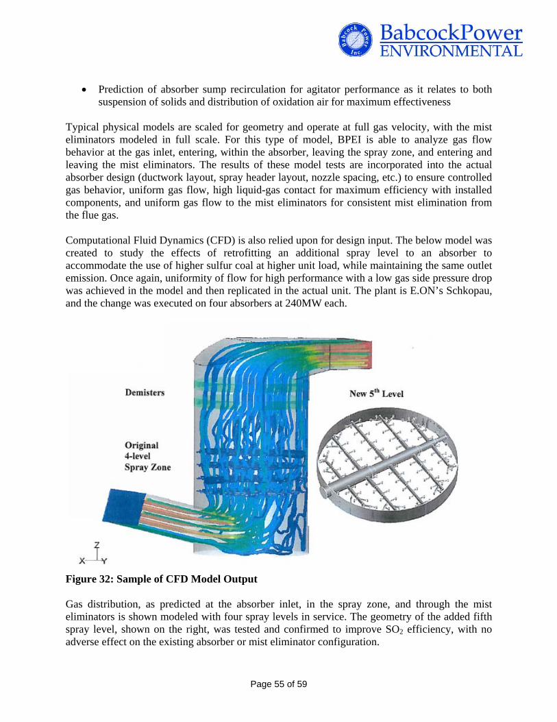
Prediction of absorber sump recirculation for agitator performance as it relates to both suspension of solids and distribution of oxidation air for maximum effectiveness
Typical physical models are scaled for geometry and operate at full gas velocity, with the mist eliminators modeled in full scale. For this type of model, BPEI is able to analyze gas flow behavior at the gas inlet, entering, within the absorber, leaving the spray zone, and entering and leaving the mist eliminators. The results of these model tests are incorporated into the actual absorber design (ductwork layout, spray header layout, nozzle spacing, etc.) to ensure controlled gas behavior, uniform gas flow, high liquid-gas contact for maximum efficiency with installed components, and uniform gas flow to the mist eliminators for consistent mist elimination from the flue gas.
Computational Fluid Dynamics (CFD) is also relied upon for design input. The below model was created to study the effects of retrofitting an additional spray level to an absorber to accommodate the use of higher sulfur coal at higher unit load, while maintaining the same outlet emission. Once again, uniformity of flow for high performance with a low gas side pressure drop was achieved in the model and then replicated in the actual unit. The plant is E.ON’s Schkopau, and the change was executed on four absorbers at 240MW each.
Figure 32: Sample of CFD Model Output
Gas distribution, as predicted at the absorber inlet, in the spray zone, and through the mist eliminators is shown modeled with four spray levels in service. The geometry of the added fifth spray level, shown on the right, was tested and confirmed to improve SO2 efficiency, with no adverse effect on the existing absorber or mist eliminator configuration.
Page 55 of 59

A similar approach could be taken to Mill Creek Units 1, 2, and 3 for predictions of gas distribution with modifications to inlet ductwork, spray header spacing, spray header layout, number and type of nozzles. CFD modeling would be especially advantageous on Unit 3 because of the shift to a different absorber unit and all the ductwork modifications associated with that change.
5.7 Construction The Case 3 construction will consist of replacing the unit 1&2 recycle pumps, piping and spray headers, unit 3 spray pipes, spray headers and recycle gearboxes will be replaced. BPEI will be adding spray nozzles, wall rings and DV210 mist eliminators on units 1,2 &3. BPEI is planning to work six months at 1-10-5 shifting to install recycle pump foundations on units 1&2 and receive materials and set up scaffolding for the outage work. The Case 3 outage is based on installing mist eliminator, spray headers, spray nozzles and wall rings into a new absorber module. This will allow the ground fabrication of the absorber and internals to take place before the outage. During a six week outage working 2-10-7 BPEI will replace the recycle pumps on units 1&2 only. On unit 3 BPEI will replace the recycle gearboxes. All three units will have the absorbers and new internals changed out as modules to reduce the outage schedule. The ROM estimate for BPEI to provide engineering, materials and construction is as follows:
o Case 3: Unit 1 - $20,428,467 o Case 3: Unit 2 - $20,567,445 o Case 3: Unit 3 - $32,944,117
5.8 Schedule Our preliminary schedule included in the attachments section is based on the following:
Case 3: Units 1, 2, & 3:4
- (6) month construction schedule working (1-10-5) One shift, ten hours per day, five days per week
- (6) week outage schedule working (2-10-7) Two shifts, ten hours per shift, seven days per week
Page 56 of 59

6. Construction Plan 6.1 Organization Overview
Babcock Power Environmental, Inc. has developed a preliminary Construction Plan that capitalizes on its engineering, product fabrication, installation, and startup expertise to provide LG&E services with an efficient retrofit design to provide low project price and short outage schedule.
6.2 Execution
Pre-Construction Upon Notice to proceed BPEI will develop a pre-construction team that will integrate BPEI engineering and fabrication with construction and develop a detailed design, project plan, and schedule. We will develop the details for constructability, value engineering, estimating, and scheduling. During this period we will refine our budgets, safety, quality, project controls, and execution plans to reflect more detailed design information. Our objective will be to assure the construction phase in a seamless part of the project delivery method. The integration of our proposal, pre-construction and construction teams will facilitate the most effective transfer of ownership and job knowledge, ensuring project safety and timely completion of construction and startup. Construction Following the integrated project schedule, BPEI will mobilize on the Mill Creek site and prepare for the receipt of WFGD components. We will construct the Recycle Pump foundations before the outages begin in order to reduce the outage lengths. Outage
The duration of the outage on Case 2 or Case 3 is based on work being completed during the construction phase. It is BPEI’s intention to minimize the outage duration to assist LG&E services in keeping the Mill Creek boilers operating.
Page 57 of 59

7. Budget Price
LG&E Services Company Contract No. 501654
Mill Creek FGD Performance Upgrade Study
Budget Engineering, Procurement and Construction Estimate February 15, 2011
Description Engineering Equipment Construction Total
Case 2: Unit 1
$1,922,629 $5,365,667 $3,253,216 $10,541,512
Case 2: Unit 2
$1,922,629 $5,365,667 $3,343,710 $10,632,006
Case 2: Unit 3
$1,922,629 $6,735,206 $5,378,000 $14,035,835
Case 3: Unit 1
$2,949,580 $10,573,006 $6,905,881 $20,428,467
Case 3: Unit 2
$2,949,580 $10,573,006 $7,044,859 $20,567,445
Case 3: Unit 3
$2,949,580 $17,504,859 $12,489,678 $32,944,117
Note: The estimate for the Mill Creek WFGD Study is a ROM (rough order of magnitude) estimate. The accuracy is based on +25% to – 10%. The pricing is based on current 2011 dollars with no escalation. The scope of the pricing for the Mill Creek Study is limited to WFGD Performance retrofit improvements. There are no other maintenance upgrades to the absorber structure or reaction tank included.
Page 58 of 59

Page 59 of 59
8. Project Schedule Our preliminary schedule included in the attachments section is based on the following:
Case 2: Units 1, 2, & 3:4
- (4) Month construction schedule working (1-10-5) One shift, ten hours per day for five days
- (3) week outage schedule working (2-10-6) Two shifts, ten hours per shift, six days per week
Case 3: Units 1, 2, & 3:4
- (6) month construction schedule working (1-10-5) One shift, ten hours per day, five days per week
- (6) week outage schedule working (2-10-7) Two shifts, ten hours per shift, seven days per week

Flue Gas Desulfurization Design Basis Spreadsheet
100524Rev. 0LG&E EnergyMill Creek Units 1, 2, and 3Kosmodale, KYWFGD Upgrade
Prepared Name Suzette PuskiPrepared Date 1/25/11Checked Name Matt QuitadamoChecked Date 1/25/2011Customer Signed NameCustomer Signed DateRemarks:
This technical data is proprietary technology of BPEI, Inc. P.O. Box 15040,Worcester, MA 01615-0040, and is submitted, lent and furnished to recipientin strict confidence with the express understanding that the recipient shall not reproduce, copy, loan, dispose of or disclose to anyone outside recipient's organization, directly or indirectly, or use said proprietary material for any purposeother than that for which it is furnished and submitted. Recipient by receiving said proprietary material agrees not to use the same in any way injurious to theinterest of BPEI, Inc., and agrees to return same upon request.
Copyright BPEI, Inc. 2011.
Project Number:Revision Number:Customer Name:Project Name:
Report Title (shown on printed sheets)
Email changes to
Location, City, StateDescription
Date: 2/15/20111 of 8

FGD Design Basis SpreadsheetScope of SupplyPlant Name:Plant Location
U1&U2 Case 2 U3 Case 2 U1&U2 Case 3 U3 3 Case 3
Flue Gas PathEquipment for Partical RemovalEquipment for Draft System
Inlet Duct Modifications x x x xEquipment for SO2 Removal
Install Wall Rings on Spray Levels 2 and 3 8 Wall Rings 8 Wall Rings 8 Wall Rings 8 Wall RingsInstall Up/Down Interior Spray Nozzles 160 128 336 336Install Up/Down Interior Wall Ring Nozzles 176 160 312 288Install Double-Down Interior Spray Nozzles 160 128 112 112Install Double-Down Wall Ring Spray Nozzles 176 160 104 96Replace Recycle Pumps 8 Pumps 8 PumpsReplace Recycle Pump Piping x xReplace Recycle Pump Gear Boxes 8 PumpsAdd Agitators and Air Lances 12 10 12 10
Equipment for SO3 RemovalEquipment for Hg RemovalEquipment for NOx RemovalEquipment for Mist Removal
Replace ME Section w/ DV210 x xother
Waste Water Treatment
UtilitiesReagentEquipment for Reagant UnloadingEquipment for Reagent StorageEquipment for Reagent Day StorageEquipment for Reagent Slurry Preparation
Increase Limestone Grind Possible Alternative May be RequiredOrganic AcidEquipment for Organic Acid System
Add organic feed system to Units 1 and 2 Possible AlternativeByproductEquipment for Byproduct TreatmentEquipment for Byproduct StorageEquipment for Byproduct Loading
Fly AshEquipment for Flyash TreatmentEquipment for Flyash StorageEquipment for Flyash Loading
Balance of PlantWater SupplyService Air SupplyInstrument Air SupplyCooling Water Supply
Process ControlEvaluate revising control logic for SO2 removal x x x x
Electrical Equipment
Structural Steel
Civil
ConstructionProcess EquipmentBalance of Plant EquipmentProcess Control incl. WiringElectrical Equipment incl. WiringStructural SteelCivil
Commissioning Yes
Performance Test No
Mill Creek Units 1, 2, and 3Rev. 0
Date: 2/15/20112 of 8

Mill Creek Units 1, 2, and 3Rev. 0
Plant Data Sheet Units DESIGNPlant Name: Mill Creek Units 1, 2, and 3Plant Location Kosmodale, KY
Site ConditionsSeismic Zone (Av/Aa) 0.09/0.07
Design Ambient Temp oF 68
Maximum Summer Ambient Temp oF 105 (per Trimble County Design)
Minimum Winter Ambient Temp oF -10 (per Trimble County Design)
Indoor Temperature Design / Range oFPlant Elevation @ Grade ft 460Elevation @ Absorber Inlet ft above TOC Units 1 & 2: 39.5, Unit 3: 28.2Atmospheric Pr. @ Absorber Inlet Elevation psia Units 1 & 2: 14.43, Unit 3: 14.44Absolute Humidity Average % max 100%Average Rainfall inches/year 50 (per Trimble County Design)Wind Speed CRM 780 section 1611.0 MPH 70 (per Trimble County Design)Snow Load CMR 780 Section 1610.0 lb/sf 15 (per Trimble County Design)
Earthquake Loads CMR 780 Section 1612.0
FGD OperationMode Part/Continuous ContinuousMonths of FGD operation/yr - Design Mon/yr 12Months of FGD operation/yr - Future Mon/yr 12Number of Boilers served by one Scrubber # Each Unit has a dedicated mult-module absorber systemBypass Operation required Yes / No No Bypass AllowedEquipment Installation Indoor/Outdoor
FGD Design Basis Spreadsheet
Date: 2/15/20113 of 8

Mill Creek Units 1, 2, and 3
Rev. 0Boiler Data Sheet Units DESIGN
Units 1 & 2 Unit 3LOAD % MCR 100 100Nominal Rating MW, Gross 350 410
MW, Net 386Boiler Manufacturer - Combustion Engineering Babcock & WilcoxFuel Fired Coal/Gas/Oil Coal CoalFiring Method Dry Bot/Wet Bot/Cyclone Opposed Wall Fired Boiler (5x4 high) w/ LNBMCR Steam Flow (Design) pph 2,326,000 3,144,000Boiler Type Balanced Draft/Pressurized Balanced Draft Balanced DraftPlant Capacity Factor Percent of Year 74.9 Gross/ 73.6 NetHours of operation per year Hours in 2000 7447 hrsNumber of Cold Starts per year Target/Actual 2 actualNumber of Hot Restarts per year Target / Actual 22 actualIgnition Fuel Fired Oil/Gas Oil OilIgnition Fuel Fired Hours/Year 800,000 galMinimum Load for FGD Operation MWnet 193 MW netFlue Gas Recirculation Y/N N NSCRSCR Reactor - Number Installed N/A 2Catalyst Type Hitachi PlateNOx inlet / outlet lbs/Mbtu 0.347 / 0.035NH3 Slip ppmdv @ ref O2 < 2.0 @ the End of LifeAir HeaterAir Heater - Number Installed - 2 2Air Heater Type Rotary/Tubualr Ljungstrom Rotary Ljungstrom RotaryAir Heater Orientation V-Shaft or H-S V-Shaft V-ShaftWill Air Heater be changed? Y/N & to what? N NAir Heater Surface configuration Model Numbers & Materials 27-VI-63 29-VI-54Air Heater Cleaning Device - Steam Soot Blowers Steam Soot BlowersAir Heater Leakage Percent 8 @ as-found condition Baseline TestESPESP's - Number Installed Number 2 2ESP Info - Configuration Single layer or Stacked TBD by LG&EESP Info - Location Cold or Hot Cold Cold
ESP Dust Loading @ ESP Temp grains/ACF @°F 3.375 @ 300oF
Dust Loading @ Eco. Out Temp grains/ACF @°F 2.294 @ 648oFESP Info - Outlet Dust Loading grains/ACF @°F TBD by LG&EESP Efficiency % TBD by LG&EWFGDWFGD - Original Supplier Name Combustion Engineering American FilterWFGD - Number Absorbers Operating / Installed Number 2 / 2 4 / 4WFGD Info - Type Single Loop or Double Loop Single SingleWFGD Info - Spray Configuration Co-Current or Counter Current Counter Current Counter Current (Co-Current on Level 2)WFGD Info - Spray Level Configuration Operating + Spare 4+0 + Tray 4+0 + TrayWFGD Info - Reagent Lime or Limestone Limestone LimestoneWFGD Info - Original Design SO2 Loading lbs/Mbtu 6.3 6.3WFGD Info - SO2 Removal Efficiency % Phase 1: 96, Phase 2: 98+ Phase 1: 96, Phase 2: 98+OtherAsh Reinjection Yes or No No NoDraft System
FD Fan, Existing Number 2 / American Standard (595 rpm @ 110oF)Design Pressure IWGFan HP HP
ID Fan, Existing Number 2/ American Standard (690,000 cfm @ 300oF) 2 / American Standard (834,950 cfm @ 300oF)Design Pressure IWG 20 45Fan HP HPID Booster Fan, Existing Number N/A N/ADesign Pressure IWG N/A N/ABooster Fan HP HP N/A N/A
FGD Design Basis Spreadsheet
Date: 2/15/20114 of 8

LG&E Mill Creek
Rev. 0FGD Load Data Sheet Units
Load Name Brown Units 1 & 2 Unit 3 Units 1 & 2 Unit 3Load MW 750 330 425 330 425Fuel Flow Rate lb/hr 676,790 148,894 148,894 128,049 95,879Firing Rate Gross10^6 BTU/Hr 5,400 5,400 5,400 5,400 5,400Excess Air % 25.0 25.0 21.5 25.0 25.0In-Leakage % 20.0 20.0 23.5 20.0 20.0Flue Gas Conditions @ Inlet Scope of Supply Ratio SCR Test Old Mat Bal RatioFlow Basis per Absorber 1 1 of 2 1 of 4 1 of 2 1 of 4Flue Gas Flow Rate lbs/h wet 9,676,853 2,128,908 1,418,869 1,832,990 1,370,888Flue Gas Flow Rate lbs/h dry 9,252,111 2,035,464 1,356,591 1,752,535 1,310,716Flue Gas Flow Rate scfm wet 1,971,997 433,839 289,144 373,536 279,366Flue Gas Flow Rate scfm dry 1,830,923 402,803 268,459 346,813 259,381Flue Gas Flow Rate acfm 3,159,481 695,086 463,259 598,469 447,593Flue Gas Temperature °F 330 330 313 330 313Flue Gas Pressure I.W.G. 14.73 14.43 14.44 14.43 14.44Flue Gas O2 % vol, dry 7.9 7.9 7.9 7.9 7.9Flue Gas CO2 % vol, dry 11.0 11.0 11.0 11.0 11.0Flue Gas H2O % vol wet 7.1 7.1 7.1 7.1 7.1Flue Gas reference O2 % vol dry 6.0 6.0 6.0 6.0 6.0Flue Gas SO2 *) ppmdv @ act O2 / lbs/MBTu 2,623 / 6.9 2,395 / 6.3 2,395 / 6.3 2,395 / 6.3 2,395 / 6.3Flue Gas SO3 *) ppmdv @ act O2 / lbs/MBTu 26 8 8 8 8Flue Gas HCl *) ppmdv @ act O2 / lbs/MBTu 44 44 44 44 44Flue Gas HF*) ppmdv @ act O2 / lbs/MBTu 9 9 9 9 9Flue Gas NOx *) ppmdv @ act O2 / lbs/MBTuFlue Gas NH3 *) ppmdv @ act O2 / lbs/MBTuFlue Gas Dust *) grains/ dcfm lbs/MBTU 0.07 / 0.41 0.07 / 0.41 0.07 / 0.41 0.07 / 0.41 0.07 / 0.41Flue Gas Hg *) ppmdv @ act O2 / lbs/MBTuFlue Gas Cd *) ppmdv @ act O2 / lbs/MBTuFlue Gas Heavy Metals *) ppmdv @ act O2 / lbs/MBTu*) Concentration range is independent of the boiler loadFlue Gas Conditions @ outlet Scope of Supply expected valuesFlue Gas Flow Rate lbs/h wet 10,356,857 2,278,509 1,518,574 1,961,796 1,467,221Flue Gas Flow Rate lbs/h dry 8,704,210 1,914,926 1,276,255 1,648,751 1,233,096Flue Gas Flow Rate scfm wet 2,184,799 480,656 320,346 413,845 309,513Flue Gas Flow Rate scfm dry 1,861,975 409,635 273,012 352,695 263,780Flue Gas Flow Rate acfm 2,624,304 577,347 384,789 497,096 371,776Flue Gas Temperature °F 128 128 128 128 128Flue Gas Pressure I.W.G. 14.62Flue Gas O2 % vol wet 11.1 11.1 11.1 11.1 11.1Flue Gas CO2 % vol wet 8 8 8 8 8Flue Gas H2O % vol wet 14.8 14.8 14.8 14.8 14.8Flue Gas SO2 *) ppmdv @ act O2 / lbs/MBTu 52 / 0.14 47 / 0.13 47 / 0.13 47 / 0.13 47 / 0.13Flue Gas SO3 *) ppmdv @ act O2 / lbs/MBTu 8 2 2 2 2Flue Gas HCl *) ppmdv @ act O2 / lbs/MBTu 0 0 0 0 0Flue Gas HF*) ppmdv @ act O2 / lbs/MBTu 0 0 0 0 0Flue Gas NOx *) ppmdv @ act O2 / lbs/MBTuFlue Gas Dust *) grains/ dcfm lbs/MBTU 0.02 / 0.12 0.02 / 0.12 0.02 / 0.12 0.02 / 0.12 0.02 / 0.12Flue Gas Hg *) ppmdv @ act O2 / lbs/MBTuFlue Gas Cd *) ppmdv @ act O2 / lbs/MBTuFlue Gas Heavy Metals *) ppmdv @ act O2 / lbs/MBTu*) Concentration range is independent of the boiler load
FGD Design Basis Spreadsheet
Date: 2/15/20115 of 8

Coal & Reagent Data Sheet Units Unit 1 & 2 Unit 3 Unit 1 & 2 Unit 3
Design Coal Name Must be filled in
Coal Source: Coal Mine 2009 2009Date Sample Taken: Date Average Average Design DesignCoal Ultimate Analysis As Received
Carbon (C) Wt% 61.61 61.61 60.30 60.30Hydrogen (H) Wt% 4.22 4.22 4.50 4.50Oxygen (O2) Wt% 7.01 7.01 6.80 6.80
Nitrogen (N2) Wt% 1.28 1.28 1.17 1.17
Sulfur (S) Wt% 3.02 3.02 3.47 3.47Chlorine (Cl) Wt% 0.06 0.06 0.07 0.07Fluorine (Fl) Wt% 0.01 0.01 0.01 0.01Moisture (Water H2O) Wt% 11.43 11.43 9.56 9.56
Ash Wt% 11.36 11.36 14.12 14.12Total Wt% 100.00 100.00 100.00 100.00
Wt. % Volatile Wt% 35.68 35.68 33.00 33.00Wt % Fixed Carbon Wt% 41.54 41.54 42.00 42.00Higher Heating Value Btu/lb, As Recvd 11,115 11,115 11,000 11,000
Reagent Name:Reagent Source:Date Sample Taken:
Reagent Analysis
CaCO3 wt.%reactive CaCO3 wt.%CaO wt.%Ca(OH)2 wt.%Fe2O3 wt.%Al2O3 wt.%SiO2 wt.%MgCO3 wt.%MgO wt.%Mg(OH)2 wt.%Chlorine (Cl) ppmFluorine (Fl) ppmMoisture wt%Inert wt%
FGD Design Basis Spreadsheet
LG&E Mill Creek
Rev. 0
Date: 2/15/20116 of 8

Process Water Data Sheet Units Design Min Max
Mist Eliminator Wash Water Analysis
pH
Conductivity mS/m
Total hardness mg/l
Carbonate hardness mg/l
Temperature °F
Suspended solids mg/l
Calcium as Ca2+ mg/l
Magnesium as Mg2+ mg/l
Sodium as Na+ mg/l
Chloride as Cl- mg/l
Sulphate SO42- mg/l
Sulphite SO32- mg/l
Make-Up Water Analysis
pH
Conductivity mS/m
Total hardness mg/l
Carbonate hardness mg/l
Temperature °F
Suspended solids mg/l
Calcium as Ca2+ mg/l
Magnesium as Mg2+ mg/l
Sodium as Na+ mg/l
Chloride as Cl- mg/l
Sulphate SO42- mg/l
Sulphite SO32- mg/l
Reclaim Water Analysis
pH
Conductivity mS/m
Total hardness mg/l
Carbonate hardness mg/l
Temperature °F
Suspended solids mg/l
Calcium as Ca2+ mg/l
Magnesium as Mg2+ mg/l
Sodium as Na+ mg/l
Chloride as Cl- mg/l
Sulphate SO42- mg/l
Sulphite SO32- mg/l
Service Water Analysis
pH
Conductivity mS/m
Total hardness mg/l
Carbonate hardness mg/l
Temperature °F
Suspended solids mg/l
Calcium as Ca2+ mg/l
Magnesium as Mg2+ mg/l
Sodium as Na+ mg/l
Chloride as Cl- mg/l
Sulphate SO42- mg/l
Sulphite SO32-
FGD Design Basis Spreadsheet
Mill Creek Units 1, 2, and 3
Rev. 0
Date: 2/15/20117 of 8

Gypsum Slurry Data Sheet Units U1&2 - Case 2 U1&2 Case 3 U3 Case 2 U3 Case 3
Recycle Slurry Analysis
Mass Flow Rate, per pump lb/hr 10,363,636 10,581,818 15,000,000 15,000,000
Volume Flow rate, per pump gpm 19,000 19,400 27,500 27,500
Estimated TDH
Spray Level 1 ft, H2O 47.3 54.7 56.4 59.7
Spray Level 2 ft, H2O 53.3 59.7 61.2 64.7
Spray Level 3 ft, H2O 58.3 64.7 64.6 69.7
Spray Level 4 ft, H2O 62.3 69.7 68.0 74.7
Specific Gravity 1.08-1.11 1.08-1.11 1.08-1.11 1.08-1.11
Density lb/ft3 66.8-69.3 66.8-69.3 66.8-69.3 66.8-69.3
Temperature °F 125-135 125-135 125-135 125-135
pH 5 to 6 5 to 6 5 to 6 5 to 6
Chloride as Cl- mg/l 5,000 5,000 5,000 5,000
Viscosity cp 7.00 7.00 7.00 7.00
Solids Content wt.% 14-18 14-18 14-18 14-18
Solids Stream
Gypsum wt.% dry 85-95 85-95 85-95 85-95
Limestone wt.% dry 1-3 1-3 1-3 1-3
Inert wt.% dry 5-15 5-15 5-15 5-15
Special Notes:
FGD Design Basis Spreadsheet
Mill Creek Units 1, 2, and 3
Rev. 0
Pump TDH calculations are preliminary for cost estimate purposes only
Compressed air is injected in the reaction tank to complete oxidation reaction
No Change to existing Unit 3 pumps in Phase 1


LLGG&&EE SSeerrvviicceess CCoommppaannyy CCoonnttrraacctt NNoo.. 550011665544
MMiillll CCrreeeekk FFGGDD PPeerrffoorrmmaannccee UUppggrraaddee SSttuuddyy
UUnniittss 11 && 22

LLGG&&EE SSeerrvviicceess CCoommppaannyy CCoonnttrraacctt NNoo.. 550011665544
MMiillll CCrreeeekk FFGGDD PPeerrffoorrmmaannccee UUppggrraaddee SSttuuddyy
UUnniittss 33 && 44


Mill Creek Units 1, 2 and 3
Rev. 0
Unit 1 Unit 2 Unit 3
Materials Qty Comments Qty Comments Qty Comments
Recycle Pumps
Replace existing 8 recycle
pumps and motors with gear
driven centrifugal pumps, 3 at
700 HP, 5 at 800 HP
Replace existing 8 recycle
pumps and motors with gear
driven centrifugal pumps, 3 at
700 HP, 5 at 800 HP No Modifications
Recycle Discharge
Piping 2000 LF
Increase diameter of all
external recycle piping to 30" 2000 LF
Increase diameter of all
external recycle piping to 30" No Modifications
Recycle suction
pipe/flanges 8 pcs
Increase diameter of all
external recycle pump suction
piping to 30" 8 pcs
Increase diameter of all
external recycle pump suction
piping to 30" No Modifications
Recycle System
Valves and inline
equipment TBD
Replacement of all inline
equipment in recycle system
with 30" Dia. Includes valves,
gaskets, replacement bolting,
fittings. TBD
Replacement of all inline
equipment in recycle system
with 30" Dia. Includes valves,
gaskets, replacement bolting,
fittings. No Modifications
Spray Nozzles 336
Replace all spray nozzles with
120 degree spray patter,
Levels 1 & 4 will use double-
down nozzles, Levels 2 & 3
will use bi-directional nozzles,
all will be bolted connection
type to connect to existing
spray header, all alloy
hardware for bolting. 336
Replace all spray nozzles with
120 degree spray patter,
Levels 1 & 4 will use double-
down nozzles, Levels 2 & 3
will use bi-directional nozzles,
all will be bolted connection
type to connect to existing
spray header, all alloy
hardware for bolting. 576
Replace all spray nozzles with
120 degree spray patter,
Levels 1 & 4 will use double-
down nozzles, Levels 2 & 3
will use bi-directional nozzles,
all will use victaulic couplings
to connect to existing spray
header, with alloy pin and bolt
on coupling.
Wall Baffles
Wall Baffles 4
Install 2 Wall Baffles, one at
Spray level 2 centerline, one
at Spray level 3 centerline,
with cutouts as necessary for
nozzle installation. 4
Install 2 Wall Baffles, one at
Spray level 2 centerline, one
at Spray level 3 centerline,
with cutouts as necessary for
nozzle installation. 8
Install 2 Wall Baffles, one at
Spray level 2 centerline, one
at Spray level 3 centerline,
with cutouts as necessary for
nozzle installation.
Oxidation Air Lances 240 LF
Install one Oxidation Air lance
per absorber agitator (6 total).
Requires new vessel
penetration, internal and
external supports. 8" Dia
Nickel Alloy Piping material. 240 LF
Install one Oxidation Air lance
per absorber agitator (6 total).
Requires new vessel
penetration, internal and
external supports. 8" Dia
Nickel Alloy Piping material. 10 pcs
Install one Oxidation Air lance
per absorber agitator (5 Per
absorber sump, 10 total).
Requires new vessel
penetration, internal and
external supports. 8" Dia
Nickel Alloy Piping material.
Air Lance Supports 6 pcs
High Nickel Alloy Material to
be used consistent with
process and Stress analysis 6 pcs
High Nickel Alloy Material to
be used consistent with
process and Stress analysis 10 pcs
High Nickel Alloy Material to
be used consistent with
process and Stress analysis
Air piping external to
sump 1000 LF
Modify existing Oxidation Air
Piping external to absorber to
accommodate a ring header
for distribution of Oxidation air
to all lances. 20" Dia CS
Piping material for ring
header, down to 8" external
feeding each lance. 1000 LF
Modify existing Oxidation Air
Piping external to absorber to
accommodate a ring header
for distribution of Oxidation air
to all lances. 20" Dia CS
Piping material for ring
header, down to 8" external
feeding each lance. TBD
Modify existing Oxidation Air
Piping external to absorber to
accommodate a ring header
for distribution of Oxidation air
to all lances. 20" Dia CS
Piping material for ring
header, down to 8" external
feeding each lance.
Air Piping hangers 59 pcs
External Oxidation Air pipe
supports to be installed on
vessel 59 pcs
External Oxidation Air pipe
supports to be installed on
vessel TBD
External Oxidation Air pipe
supports to be installed on
vessel
Agitators 6
Install (6) side mount absorber
agitators, new vessel
penetration, external supports
to grade required for each.
Ekato, 2M blades anticipated
for use. 6
Install (6) side mount absorber
agitators, new vessel
penetration, external supports
to grade required for each.
Ekato, 2M blades anticipated
for use. 10
Install (5) side mount absorber
agitators per sump (10 total),
new vessel penetration,
external supports to grade
required for each. Ekato,
1.6M blades anticipated for
use.
FGD Upgrades - Equipment to be Modified
Slurry Recycle System
Oxidation Air System
Case 2
1 of 3 Date: 2/9/2011

Mill Creek Units 1, 2 and 3
Rev. 0
Unit 1 Unit 2 Unit 3
Materials Qty Comments Qty Comments Qty Comments
Recycle Pumps 8
Replace existing 8 recycle
pumps and motors with gear
driven centrifugal pumps, 3 at
700 HP, 5 at 800 HP 8
Replace existing 8 recycle
pumps and motors with gear
driven centrifugal pumps, 3 at
700 HP, 5 at 800 HP 8 Gear Boxes regeared
Recycle Discharge
Piping 2000 LF
Increase diameter of all
external recycle piping to 30" 2000 LF
Increase diameter of all
external recycle piping to 30" N/A
Recycle suction
pipe/flanges 8 pcs
Increase diameter of all
external recycle pump suction
piping to 30" 8 pcs
Increase diameter of all
external recycle pump suction
piping to 30" No Modifications
Recycle System
Valves
and inline equipment
Replacement of all inline
equipment in recycle system
with 30" Dia. Includes valves,
gaskets, replacement bolting,
fittings.
Replacement of all inline
equipment in recycle system
with 30" Dia. Includes valves,
gaskets, replacement bolting,
fittings. No Modifications
Spray Nozzles 432
Replace all spray nozzles with
120 degree spray patter, Level
4 will use double-down
nozzles, Levels 1, 2 & 3 will
use bi-directional nozzles, all
will be bolted connection type
to connect to existing spray
header, all alloy hardware for
bolting. 432
Replace all spray nozzles with
120 degree spray patter, Level
4 will use double-down
nozzles, Levels 1, 2 & 3 will
use bi-directional nozzles, all
will be bolted connection type
to connect to existing spray
header, all alloy hardware for
bolting. 832
Replace all spray nozzles with
120 degree spray patter, Level
4 will use double-down
nozzles, Levels 1, 2 & 3 will
use bi-directional nozzles, all
will use victaulic couplings to
connect to existing spray
header, with alloy pin and bolt
on coupling.
Spray Headers 8
Spray headers will be modified
by addition of nozzles to each
level and relocation of the
levels to BPEI specified
elevations above the
perforated tray 8
Spray headers will be modified
by addition of nozzles to each
level and relocation of the
levels to BPEI specified
elevations above the
perforated tray 16
Spray headers will be modified
by addition of nozzles to each
level and relocation of the
levels to BPEI specified
elevations above the
perforated tray
Spray pipe hangers TBD
Additional pipe hangers will be
installed to accommodate the
additional nozzles and spray
header piping added. TBD
Additional pipe hangers will be
installed to accommodate the
additional nozzles and spray
header piping added. TBD
Additional pipe hangers will be
installed to accommodate the
additional nozzles and spray
header piping added.
Wall Baffles 4
Install 2 Wall Baffles, one at
Spray level 2 centerline, one
at Spray level 3 centerline,
with cutouts as necessary for
nozzle installation. 4
Install 2 Wall Baffles, one at
Spray level 2 centerline, one at
Spray level 3 centerline, with
cutouts as necessary for
nozzle installation. 8
Install 2 Wall Baffles, one at
Spray level 2 centerline, one at
Spray level 3 centerline, with
cutouts as necessary for
nozzle installation.
Oxidation Air Lances 6pcs
Install one Oxidation Air lance
per absorber agitator (6 total).
Requires new vessel
penetration, internal and
external supports. 8" Dia
Nickel Alloy Piping material. 6pcs
Install one Oxidation Air lance
per absorber agitator (6 total).
Requires new vessel
penetration, internal and
external supports. 8" Dia
Nickel Alloy Piping material. 10 pcs
Install one Oxidation Air lance
per absorber agitator (5 Per
absorber sump, 10 total).
Requires new vessel
penetration, internal and
external supports. 8" Dia
Nickel Alloy Piping material.
Air Lance Supports 6 pcs
High Nickel Alloy Material to
be used consistent with
process and Stress analysis 6 pcs
High Nickel Alloy Material to be
used consistent with process
and Stress analysis 10 pcs
High Nickel Alloy Material to be
used consistent with process
and Stress analysis
Air piping external to
sump 1000 LF
Modify existing Oxidation Air
Piping external to absorber to
accommodate a ring header
for distribution of Oxidation air
to all lances. 20" Dia CS
Piping material for ring header,
down to 8" external feeding
each lance. 1000 LF
Modify existing Oxidation Air
Piping external to absorber to
accommodate a ring header for
distribution of Oxidation air to
all lances. 20" Dia CS Piping
material for ring header, down
to 8" external feeding each
lance. TBD
Modify existing Oxidation Air
Piping external to absorber to
accommodate a ring header for
distribution of Oxidation air to
all lances. 20" Dia CS Piping
material for ring header, down
to 8" external feeding each
lance.
Air Piping hangers 59 pcs
External Oxidation Air pipe
supports to be installed on
vessel 59 pcs
External Oxidation Air pipe
supports to be installed on
vessel TBD
External Oxidation Air pipe
supports to be installed on
vessel
Case 3FGD Upgrades - Equipment to be Modified
Slurry Recycle System
Oxidation Air System
Wall Baffles
2 of 3 Date: 2/9/2011

Agitators 6
Install (6) side mount absorber
agitators, new vessel
penetration, external supports
to grade required for each.
Ekato, 2M blades anticipated
for use. 6
Install (6) side mount absorber
agitators, new vessel
penetration, external supports
to grade required for each.
Ekato, 2M blades anticipated
for use. 10
Install (5) side mount absorber
agitators per sump (10 total),
new vessel penetration,
external supports to grade
required for each. Ekato, 1.6M
blades anticipated for use.
Outlet expansion joint 88 lf
Outlet Duct Expansion joints
will be replaced. 88 lf
Outlet Duct Expansion joints
will be replaced. TBD
Outlet Duct Expansion joints
will be replaced.
317L Absorber shell 16,744 sf
Absorber shell will be modified
with relocation of Spray
Headers. Original
penetrations will be filled while
new ones are cut. 16,744 sf
Absorber shell will be modified
with relocation of Spray
Headers. Original penetrations
will be filled while new ones
are cut.
Absorber shell will be modified
with relocation of Spray
Headers. Original penetrations
will be filled while new ones
are cut.
Absorber Reheater
Section
Reheater section will be
removed and new ME section
will be installed in its place
Reheater section will be
removed and new ME section
will be installed in its place
Reheater section will be
removed and new ME section
will be installed in its place
DV 210 Mist Eliminator
and spray wash
system TBD
In the previous Reheat section
new Munters DV210 modular
Mist Eliminator sections will be
installed along with new ME
wash piping system to supply
wash water. TBD
In the previous Reheat section
new Munters DV210 modular
Mist Eliminator sections will be
installed along with new ME
wash piping system to supply
wash water. TBD
In the previous Reheat section
new Munters DV210 modular
Mist Eliminator sections will be
installed along with new ME
wash piping system to supply
wash water.
Absorber Shell and Ductwork Modifications
3 of 3 Date: 2/9/2011

Rev 0
AREA ITEM DESCRIPTIONBasic Engrg
Detail Design
Procure Fab DeliverErect
ConsultErection
Commission
Test Training
A Oxidation Air System Oxidation Air Compressor By Others By Others By Others By Others By Others By Others By Others By Others By Others By OthersOxidation Air Agitators BPEI BPEI BPEI BPEI BPEI BPEI BPEI BPEI BPEI BPEIOxidation Air Pressure Relief Valves BPEI BPEI BPEI BPEI BPEI BPEI BPEI BPEI BPEI BPEIExternal Headers BPEI BPEI BPEI BPEI BPEI BPEI BPEI BPEI BPEI BPEIInternal Lances BPEI BPEI BPEI BPEI BPEI BPEI BPEI BPEI BPEI BPEISpray Nozzles BPEI BPEI BPEI BPEI BPEI BPEI BPEI BPEI BPEI BPEIInlet Silencer By Others By Others By Others By Others By Others By Others By Others By Others By Others By OthersInlet Filter By Others By Others By Others By Others By Others By Others By Others By Others By Others By OthersInstrumentation By Others By Others By Others By Others By Others By Others By Others By Others By Others By OthersControl Valves By Others By Others By Others By Others By Others By Others By Others By Others By Others By OthersActuated Valves By Others By Others By Others By Others By Others By Others By Others By Others By Others By OthersManuel Valves By Others By Others By Others By Others By Others By Others By Others By Others By Others By OthersPLC Controls By Others By Others By Others By Others By Others By Others By Others By Others By Others By OthersAccess Steel (including handrails, platforms, stairs, flooring, grating e By Others By Others By Others By Others By Others By Others By Others By Others By Others By OthersStructural Steel By Others By Others By Others By Others By Others By Others By Others By Others By Others By OthersFoundations By Others By Others By Others By Others By Others By Others By Others By Others By Others By OthersElectrical Hoists By Others By Others By Others By Others By Others By Others By Others By Others By Others By OthersElectrical Power Supply By Others By Others By Others By Others By Others By Others By Others By Others By Others By OthersMotor Starters and Control Centers By Others By Others By Others By Others By Others By Others By Others By Others By Others By OthersMotors low Voltage By Others By Others By Others By Others By Others By Others By Others By Others By Others By OthersMotors medium Voltage By Others By Others By Others By Others By Others By Others By Others By Others By Others By OthersPipes > 2 in incl Support BPEI BPEI BPEI BPEI BPEI BPEI BPEI BPEI BPEI BPEIPipes < 2 in incl Support BPEI BPEI BPEI BPEI BPEI BPEI BPEI BPEI BPEI BPEIRaceway, Conduit, Pullboxes, Wiring, Cabling (excludes skid equipm By Others By Others By Others By Others By Others By Others By Others By Others By Others By OthersRaceway, Conduit, Pullboxes, Wiring, Cabling on Skids By Others By Others By Others By Others By Others By Others By Others By Others By Others By OthersHeat Tracing (Freeze Protection) By Others By Others By Others By Others By Others By Others By Others By Others By Others By OthersCathodic Protection By Others By Others By Others By Others By Others By Others By Others By Others By Others By OthersPlant Electrical and Mechanical Tie-In By Others By Others By Others By Others By Others By Others By Others By Others By Others By Others
A Absorber Recycle Pumps System
LG&E Service CompanyContract No. 501654
Mill Creek FGD Performance Upgrade StudyCase 2 : Units 1, 2 & 3:4
1 of 4

Rev 0
AREA ITEM DESCRIPTIONBasic Engrg
Detail Design
Procure Fab DeliverErect
ConsultErection
Commission
Test Training
LG&E Service CompanyContract No. 501654
Mill Creek FGD Performance Upgrade StudyCase 2 : Units 1, 2 & 3:4
Absorber Recycle Pumps incl Gear Box BPEI BPEI BPEI BPEI BPEI BPEI BPEI BPEI BPEI BPEIOil Circulation and Coolers BPEI BPEI BPEI BPEI BPEI BPEI BPEI BPEI BPEI BPEIAbsorber Recycle Pipes External BPEI BPEI BPEI BPEI BPEI BPEI BPEI BPEI BPEI BPEIAbsorber Recycle Pipes Internal BPEI BPEI BPEI BPEI BPEI BPEI BPEI BPEI BPEI BPEIexpansion Joints BPEI BPEI BPEI BPEI BPEI BPEI BPEI BPEI BPEI BPEISpray Nozzles BPEI BPEI BPEI BPEI BPEI BPEI BPEI BPEI BPEI BPEIInstrumentation BPEI BPEI BPEI BPEI BPEI BPEI BPEI BPEI BPEI BPEIActuated Valves By Others By Others By Others By Others By Others By Others By Others By Others By Others By OthersManuel Valves By Others By Others By Others By Others By Others By Others By Others By Others By Others By OthersPLC Controls BPEI BPEI BPEI BPEI BPEI BPEI BPEI BPEI BPEI BPEIAccess Steel (including handrails, platforms, stairs, flooring, grating e By Others By Others By Others By Others By Others By Others By Others By Others By Others By OthersStructural Steel By Others By Others By Others By Others By Others By Others By Others By Others By Others By OthersFoundations BPEI BPEI BPEI BPEI BPEI BPEI BPEI BPEI BPEI BPEIElectrical Hoists By Others By Others By Others By Others By Others By Others By Others By Others By Others By OthersElectrical Power Supply BPEI BPEI BPEI BPEI BPEI BPEI BPEI BPEI BPEI BPEIMotor Starters and Control Centers BPEI BPEI BPEI BPEI BPEI BPEI BPEI BPEI BPEI BPEIMotors low Voltage BPEI BPEI BPEI BPEI BPEI BPEI BPEI BPEI BPEI BPEIMotors medium Voltage BPEI BPEI BPEI BPEI BPEI BPEI BPEI BPEI BPEI BPEIPipes > 2 in incl Support BPEI BPEI BPEI BPEI BPEI BPEI BPEI BPEI BPEI BPEIPipes < 2 in incl Support BPEI BPEI BPEI BPEI BPEI BPEI BPEI BPEI BPEI BPEIRaceway, Conduit, Pullboxes, Wiring, Cabling (excludes skid equipm BPEI BPEI BPEI BPEI BPEI BPEI BPEI BPEI BPEI BPEIRaceway, Conduit, Pullboxes, Wiring, Cabling on Skids BPEI BPEI BPEI BPEI BPEI BPEI BPEI BPEI BPEI BPEIHeat Tracing (Freeze Protection) BPEI BPEI BPEI BPEI BPEI BPEI BPEI BPEI BPEI BPEICathodic Protection BPEI BPEI BPEI BPEI BPEI BPEI BPEI BPEI BPEI BPEIPlant Electrical and Mechanical Tie-In BPEI BPEI BPEI BPEI BPEI BPEI BPEI BPEI BPEI BPEI
A Absorber Tower Flow Models By Others By Others By Others By Others By Others By Others By Others By Others By Others By OthersAbsorber Material By Others By Others By Others By Others By Others By Others By Others By Others By Others By OthersSide-Mounted Agitators BPEI BPEI BPEI BPEI BPEI BPEI BPEI BPEI BPEI BPEIMist Eliminators Blades By Others By Others By Others By Others By Others By Others By Others By Others By Others By OthersMist Eliminators Support Structure By Others By Others By Others By Others By Others By Others By Others By Others By Others By OthersMist Eliminator Wash Headers internal By Others By Others By Others By Others By Others By Others By Others By Others By Others By Others
2 of 4

Rev 0
AREA ITEM DESCRIPTIONBasic Engrg
Detail Design
Procure Fab DeliverErect
ConsultErection
Commission
Test Training
LG&E Service CompanyContract No. 501654
Mill Creek FGD Performance Upgrade StudyCase 2 : Units 1, 2 & 3:4
Mist Eliminator Wash Headers external By Others By Others By Others By Others By Others By Others By Others By Others By Others By OthersMist Eliminator Wash Headers internal Support By Others By Others By Others By Others By Others By Others By Others By Others By Others By OthersAbsorber Internals BPEI BPEI BPEI BPEI BPEI BPEI BPEI BPEI BPEI BPEIInspection Access Doors By Others By Others By Others By Others By Others By Others By Others By Others By Others By OthersGas Sample Test Ports By Others By Others By Others By Others By Others By Others By Others By Others By Others By OthersInstrumentation By Others By Others By Others By Others By Others By Others By Others By Others By Others By OthersAccess Steel (including handrails, platforms, stairs, flooring, grating e By Others By Others By Others By Others By Others By Others By Others By Others By Others By OthersStructural Steel By Others By Others By Others By Others By Others By Others By Others By Others By Others By OthersFoundations By Others By Others By Others By Others By Others By Others By Others By Others By Others By OthersElectrical Hoists By Others By Others By Others By Others By Others By Others By Others By Others By Others By OthersElectrical Power Supply By Others By Others By Others By Others By Others By Others By Others By Others By Others By OthersMotor Starters and Control Centers By Others By Others By Others By Others By Others By Others By Others By Others By Others By OthersMotors low Voltage By Others By Others By Others By Others By Others By Others By Others By Others By Others By OthersRaceway, Conduit, Pullboxes, Wiring, Cabling (excludes skid equipm By Others By Others By Others By Others By Others By Others By Others By Others By Others By OthersPlant Electrical and Mechanical Tie-In By Others By Others By Others By Others By Others By Others By Others By Others By Others By Others
Project / Construction Administration Enviromental Licensing and Permits By Others By Others By Others By Others By Others By Others By Others By Others By Others By OthersBuilding Licensing and Permits By Others By Others By Others By Others By Others By Others By Others By Others By Others By OthersLimestone Licensing and Permits By Others By Others By Others By Others By Others By Others By Others By Others By Others By OthersProject Master Schedule BPEI BPEI BPEI BPEI BPEI BPEI BPEI BPEI BPEI BPEIProject Schedule- Design,Procure,Fabricate&Deliver BPEI BPEI BPEI BPEI BPEI BPEI BPEI BPEI BPEI BPEIConstruction Safety Program BPEI BPEI BPEI BPEI BPEI BPEI BPEI BPEI BPEI BPEIProject Labor Plan BPEI BPEI BPEI BPEI BPEI BPEI BPEI BPEI BPEI BPEIQA/QC Program BPEI BPEI BPEI BPEI BPEI BPEI BPEI BPEI BPEI BPEIStart-up Field Service, Equipment Commisioning & Turnover BPEI BPEI BPEI BPEI BPEI BPEI BPEI BPEI BPEI BPEIPersonnel Training BPEI BPEI BPEI BPEI BPEI BPEI BPEI BPEI BPEI BPEIO & M Manuals BPEI BPEI BPEI BPEI BPEI BPEI BPEI BPEI BPEI BPEIOptimization & Acceptance Testing BPEI BPEI BPEI BPEI BPEI BPEI BPEI BPEI BPEI BPEIEquipment Storage BPEI BPEI BPEI BPEI BPEI BPEI BPEI BPEI BPEI BPEIEquipment Precommision Maintenance BPEI BPEI BPEI BPEI BPEI BPEI BPEI BPEI BPEI BPEIConstruction Facilities - Temporary BPEI BPEI BPEI BPEI BPEI BPEI BPEI BPEI BPEI BPEI
3 of 4

Rev 0
AREA ITEM DESCRIPTIONBasic Engrg
Detail Design
Procure Fab DeliverErect
ConsultErection
Commission
Test Training
LG&E Service CompanyContract No. 501654
Mill Creek FGD Performance Upgrade StudyCase 2 : Units 1, 2 & 3:4
Construction Facilities - Permanent By Others By Others By Others By Others By Others By Others By Others By Others By Others By OthersSite Clean-up BPEI BPEI BPEI BPEI BPEI BPEI BPEI BPEI BPEI BPEIAsbestos Testing & Removal By Others By Others By Others By Others By Others By Others By Others By Others By Others By OthersLead Paint Testing & Removal By Others By Others By Others By Others By Others By Others By Others By Others By Others By OthersFinish Painting and Field Touch-up BPEI BPEI BPEI BPEI BPEI BPEI BPEI BPEI BPEI BPEI
4 of 4

Rev 0
AREA ITEM DESCRIPTIONBasic Engrg
Detail Design
Procure Fab DeliverErect
ConsultErection
Commission
Test Training
C Gas Path
Inlet Ductwork By Others By Others By Others By Others By Others By Others By Others By Others By Others By OthersOutlet Ductwork By Others By Others By Others By Others By Others By Others By Others By Others By Others By OthersFlow Models By Others By Others By Others By Others By Others By Others By Others By Others By Others By OthersExpansion Joints BPEI BPEI BPEI BPEI BPEI BPEI BPEI BPEI BPEI BPEIDuctwork Internals (flow screen, hoist beam) By Others By Others By Others By Others By Others By Others By Others By Others By Others By OthersNew ID & Booster Fans By Others By Others By Others By Others By Others By Others By Others By Others By Others By OthersNew ID & Booster Fan Motors By Others By Others By Others By Others By Others By Others By Others By Others By Others By OthersInspection Access Doors By Others By Others By Others By Others By Others By Others By Others By Others By Others By OthersGas Sample Test Ports By Others By Others By Others By Others By Others By Others By Others By Others By Others By OthersInsulation & Lagging For All Components By Others By Others By Others By Others By Others By Others By Others By Others By Others By OthersInstrumentation By Others By Others By Others By Others By Others By Others By Others By Others By Others By OthersActuated Valves/Dampers By Others By Others By Others By Others By Others By Others By Others By Others By Others By OthersManuel Valves/Dampers By Others By Others By Others By Others By Others By Others By Others By Others By Others By OthersAccess Steel (including handrails, platforms, stairs, flooring, grating e By Others By Others By Others By Others By Others By Others By Others By Others By Others By OthersStructural Steel By Others By Others By Others By Others By Others By Others By Others By Others By Others By OthersFoundations By Others By Others By Others By Others By Others By Others By Others By Others By Others By OthersElectrical Power Supply By Others By Others By Others By Others By Others By Others By Others By Others By Others By OthersMotor Starters and Control Centers By Others By Others By Others By Others By Others By Others By Others By Others By Others By OthersMotors low Voltage By Others By Others By Others By Others By Others By Others By Others By Others By Others By OthersPipes > 2 in incl Support By Others By Others By Others By Others By Others By Others By Others By Others By Others By OthersPipes < 2 in incl Support By Others By Others By Others By Others By Others By Others By Others By Others By Others By OthersRaceway, Conduit, Pullboxes, Wiring, Cabling (excludes skid equipm By Others By Others By Others By Others By Others By Others By Others By Others By Others By OthersHeat Tracing (Freeze Protection) By Others By Others By Others By Others By Others By Others By Others By Others By Others By OthersCathodic Protection By Others By Others By Others By Others By Others By Others By Others By Others By Others By OthersPlant Electrical and Mechanical Tie-In By Others By Others By Others By Others By Others By Others By Others By Others By Others By Others
A Oxidation Air System Oxidation Air Compressor By Others By Others By Others By Others By Others By Others By Others By Others By Others By OthersOxidation Air Agitators BPEI BPEI BPEI BPEI BPEI BPEI BPEI BPEI BPEI BPEIOxidation Air Pressure Relief Valves BPEI BPEI BPEI BPEI BPEI BPEI BPEI BPEI BPEI BPEIExternal Headers BPEI BPEI BPEI BPEI BPEI BPEI BPEI BPEI BPEI BPEI
LG&E Service CompanyContract No. 501654
Mill Creek FGD Performance Upgrade StudyCase 3 : Units 1, 2 & 3:4
1 of 4

Rev 0
AREA ITEM DESCRIPTIONBasic Engrg
Detail Design
Procure Fab DeliverErect
ConsultErection
Commission
Test Training
LG&E Service CompanyContract No. 501654
Mill Creek FGD Performance Upgrade StudyCase 3 : Units 1, 2 & 3:4
Internal Lances BPEI BPEI BPEI BPEI BPEI BPEI BPEI BPEI BPEI BPEISpray Nozzles BPEI BPEI BPEI BPEI BPEI BPEI BPEI BPEI BPEI BPEIInlet Silencer By Others By Others By Others By Others By Others By Others By Others By Others By Others By OthersInlet Filter By Others By Others By Others By Others By Others By Others By Others By Others By Others By OthersInstrumentation By Others By Others By Others By Others By Others By Others By Others By Others By Others By OthersControl Valves By Others By Others By Others By Others By Others By Others By Others By Others By Others By OthersActuated Valves By Others By Others By Others By Others By Others By Others By Others By Others By Others By OthersManuel Valves By Others By Others By Others By Others By Others By Others By Others By Others By Others By OthersPLC Controls By Others By Others By Others By Others By Others By Others By Others By Others By Others By OthersAccess Steel (including handrails, platforms, stairs, flooring, grating e By Others By Others By Others By Others By Others By Others By Others By Others By Others By OthersStructural Steel By Others By Others By Others By Others By Others By Others By Others By Others By Others By OthersFoundations By Others By Others By Others By Others By Others By Others By Others By Others By Others By OthersElectrical Hoists By Others By Others By Others By Others By Others By Others By Others By Others By Others By OthersElectrical Power Supply By Others By Others By Others By Others By Others By Others By Others By Others By Others By OthersMotor Starters and Control Centers By Others By Others By Others By Others By Others By Others By Others By Others By Others By OthersMotors low Voltage By Others By Others By Others By Others By Others By Others By Others By Others By Others By OthersMotors medium Voltage By Others By Others By Others By Others By Others By Others By Others By Others By Others By OthersPipes > 2 in incl Support BPEI BPEI BPEI BPEI BPEI BPEI BPEI BPEI BPEI BPEIPipes < 2 in incl Support BPEI BPEI BPEI BPEI BPEI BPEI BPEI BPEI BPEI BPEIRaceway, Conduit, Pullboxes, Wiring, Cabling (excludes skid equipm By Others By Others By Others By Others By Others By Others By Others By Others By Others By OthersRaceway, Conduit, Pullboxes, Wiring, Cabling on Skids By Others By Others By Others By Others By Others By Others By Others By Others By Others By OthersHeat Tracing (Freeze Protection) By Others By Others By Others By Others By Others By Others By Others By Others By Others By OthersCathodic Protection By Others By Others By Others By Others By Others By Others By Others By Others By Others By OthersPlant Electrical and Mechanical Tie-In By Others By Others By Others By Others By Others By Others By Others By Others By Others By Others
A Absorber Recycle Pumps System Absorber Recycle Pumps incl Gear Box - Unit 3 Gear Boxes only BPEI BPEI BPEI BPEI BPEI BPEI BPEI BPEI BPEI BPEIOil Circulation and Coolers BPEI BPEI BPEI BPEI BPEI BPEI BPEI BPEI BPEI BPEIAbsorber Recycle Pipes External BPEI BPEI BPEI BPEI BPEI BPEI BPEI BPEI BPEI BPEIAbsorber Recycle Pipes Internal BPEI BPEI BPEI BPEI BPEI BPEI BPEI BPEI BPEI BPEIexpansion Joints BPEI BPEI BPEI BPEI BPEI BPEI BPEI BPEI BPEI BPEISpray Nozzles BPEI BPEI BPEI BPEI BPEI BPEI BPEI BPEI BPEI BPEIInstrumentation BPEI BPEI BPEI BPEI BPEI BPEI BPEI BPEI BPEI BPEI
2 of 4

Rev 0
AREA ITEM DESCRIPTIONBasic Engrg
Detail Design
Procure Fab DeliverErect
ConsultErection
Commission
Test Training
LG&E Service CompanyContract No. 501654
Mill Creek FGD Performance Upgrade StudyCase 3 : Units 1, 2 & 3:4
Actuated Valves By Others By Others By Others By Others By Others By Others By Others By Others By Others By OthersManuel Valves By Others By Others By Others By Others By Others By Others By Others By Others By Others By OthersPLC Controls BPEI BPEI BPEI BPEI BPEI BPEI BPEI BPEI BPEI BPEIAccess Steel (including handrails, platforms, stairs, flooring, grating e By Others By Others By Others By Others By Others By Others By Others By Others By Others By OthersStructural Steel By Others By Others By Others By Others By Others By Others By Others By Others By Others By OthersFoundations BPEI BPEI BPEI BPEI BPEI BPEI BPEI BPEI BPEI BPEIElectrical Hoists By Others By Others By Others By Others By Others By Others By Others By Others By Others By OthersElectrical Power Supply BPEI BPEI BPEI BPEI BPEI BPEI BPEI BPEI BPEI BPEIMotor Starters and Control Centers BPEI BPEI BPEI BPEI BPEI BPEI BPEI BPEI BPEI BPEIMotors low Voltage BPEI BPEI BPEI BPEI BPEI BPEI BPEI BPEI BPEI BPEIMotors medium Voltage BPEI BPEI BPEI BPEI BPEI BPEI BPEI BPEI BPEI BPEIPipes > 2 in incl Support BPEI BPEI BPEI BPEI BPEI BPEI BPEI BPEI BPEI BPEIPipes < 2 in incl Support BPEI BPEI BPEI BPEI BPEI BPEI BPEI BPEI BPEI BPEIRaceway, Conduit, Pullboxes, Wiring, Cabling (excludes skid equipm BPEI BPEI BPEI BPEI BPEI BPEI BPEI BPEI BPEI BPEIRaceway, Conduit, Pullboxes, Wiring, Cabling on Skids BPEI BPEI BPEI BPEI BPEI BPEI BPEI BPEI BPEI BPEIHeat Tracing (Freeze Protection) BPEI BPEI BPEI BPEI BPEI BPEI BPEI BPEI BPEI BPEICathodic Protection BPEI BPEI BPEI BPEI BPEI BPEI BPEI BPEI BPEI BPEIPlant Electrical and Mechanical Tie-In BPEI BPEI BPEI BPEI BPEI BPEI BPEI BPEI BPEI BPEI
A Absorber Tower Flow Models BPEI BPEI BPEI BPEI BPEI BPEI BPEI BPEI BPEI BPEIAbsorber Material BPEI BPEI BPEI BPEI BPEI BPEI BPEI BPEI BPEI BPEISide-Mounted Agitators BPEI BPEI BPEI BPEI BPEI BPEI BPEI BPEI BPEI BPEIMist Eliminators Blades BPEI BPEI BPEI BPEI BPEI BPEI BPEI BPEI BPEI BPEIMist Eliminators Support Structure BPEI BPEI BPEI BPEI BPEI BPEI BPEI BPEI BPEI BPEIMist Eliminator Wash Headers internal BPEI BPEI BPEI BPEI BPEI BPEI BPEI BPEI BPEI BPEIMist Eliminator Wash Headers external BPEI BPEI BPEI BPEI BPEI BPEI BPEI BPEI BPEI BPEIMist Eliminator Wash Headers internal Support BPEI BPEI BPEI BPEI BPEI BPEI BPEI BPEI BPEI BPEIAbsorber Internals BPEI BPEI BPEI BPEI BPEI BPEI BPEI BPEI BPEI BPEIInspection Access Doors By Others By Others By Others By Others By Others By Others By Others By Others By Others By OthersGas Sample Test Ports By Others By Others By Others By Others By Others By Others By Others By Others By Others By OthersInstrumentation BPEI BPEI BPEI BPEI BPEI BPEI BPEI BPEI BPEI BPEIAccess Steel (including handrails, platforms, stairs, flooring, grating e By Others By Others By Others By Others By Others By Others By Others By Others By Others By Others
3 of 4

Rev 0
AREA ITEM DESCRIPTIONBasic Engrg
Detail Design
Procure Fab DeliverErect
ConsultErection
Commission
Test Training
LG&E Service CompanyContract No. 501654
Mill Creek FGD Performance Upgrade StudyCase 3 : Units 1, 2 & 3:4
Structural Steel By Others By Others By Others By Others By Others By Others By Others By Others By Others By OthersFoundations By Others By Others By Others By Others By Others By Others By Others By Others By Others By OthersElectrical Hoists By Others By Others By Others By Others By Others By Others By Others By Others By Others By OthersElectrical Power Supply By Others By Others By Others By Others By Others By Others By Others By Others By Others By OthersMotor Starters and Control Centers By Others By Others By Others By Others By Others By Others By Others By Others By Others By OthersMotors low Voltage By Others By Others By Others By Others By Others By Others By Others By Others By Others By OthersRaceway, Conduit, Pullboxes, Wiring, Cabling (excludes skid equipm By Others By Others By Others By Others By Others By Others By Others By Others By Others By OthersPlant Electrical and Mechanical Tie-In By Others By Others By Others By Others By Others By Others By Others By Others By Others By Others
Project / Construction Administration Enviromental Licensing and Permits By Others By Others By Others By Others By Others By Others By Others By Others By Others By OthersBuilding Licensing and Permits By Others By Others By Others By Others By Others By Others By Others By Others By Others By OthersLimestone Licensing and Permits By Others By Others By Others By Others By Others By Others By Others By Others By Others By OthersProject Master Schedule BPEI BPEI BPEI BPEI BPEI BPEI BPEI BPEI BPEI BPEIProject Schedule- Design,Procure,Fabricate&Deliver BPEI BPEI BPEI BPEI BPEI BPEI BPEI BPEI BPEI BPEIConstruction Safety Program BPEI BPEI BPEI BPEI BPEI BPEI BPEI BPEI BPEI BPEIProject Labor Plan BPEI BPEI BPEI BPEI BPEI BPEI BPEI BPEI BPEI BPEIQA/QC Program BPEI BPEI BPEI BPEI BPEI BPEI BPEI BPEI BPEI BPEIStart-up Field Service, Equipment Commisioning & Turnover BPEI BPEI BPEI BPEI BPEI BPEI BPEI BPEI BPEI BPEIPersonnel Training BPEI BPEI BPEI BPEI BPEI BPEI BPEI BPEI BPEI BPEIO & M Manuals BPEI BPEI BPEI BPEI BPEI BPEI BPEI BPEI BPEI BPEIOptimization & Acceptance Testing BPEI BPEI BPEI BPEI BPEI BPEI BPEI BPEI BPEI BPEIEquipment Storage BPEI BPEI BPEI BPEI BPEI BPEI BPEI BPEI BPEI BPEIEquipment Precommision Maintenance BPEI BPEI BPEI BPEI BPEI BPEI BPEI BPEI BPEI BPEIConstruction Facilities - Temporary BPEI BPEI BPEI BPEI BPEI BPEI BPEI BPEI BPEI BPEIConstruction Facilities - Permanent By Others By Others By Others By Others By Others By Others By Others By Others By Others By OthersSite Clean-up BPEI BPEI BPEI BPEI BPEI BPEI BPEI BPEI BPEI BPEIAsbestos Testing & Removal By Others By Others By Others By Others By Others By Others By Others By Others By Others By OthersLead Paint Testing & Removal By Others By Others By Others By Others By Others By Others By Others By Others By Others By OthersFinish Painting and Field Touch-up BPEI BPEI BPEI BPEI BPEI BPEI BPEI BPEI BPEI BPEI
4 of 4

Activity Name Contract Number
OrigDur
LG&E Mill Creek Units 1-4 WFGD Upgrade StudyLG&E Mill Creek Units 1-4 WFGD Upgrade Study 771
0
No Mill Creek Unit # No Mill Creek Unit # 0
EngineeringEngineering 0
Case - 2Case - 2 714
Unit #1Unit #1 337
EngineeringEngineering 80
ProcurementProcurement 93
Fabrication & DeliveryFabrication & Delivery 253
ConstructionConstruction 80
OutageOutage 19
Startup & CommissioningStartup & Commissioning 20
Unit #2Unit #2 337
EngineeringEngineering 80
ProcurementProcurement 93
Fabrication & DeliveryFabrication & Delivery 253
ConstructionConstruction 80
OutageOutage 19
Startup & CommissioningStartup & Commissioning 20
Unit #3Unit #3 274
EngineeringEngineering 80
ProcurementProcurement 80
Fabrication & DeliveryFabrication & Delivery 200
ConstructionConstruction 21
OutageOutage 23
Startup & CommissioningStartup & Commissioning 20
Case - 3Case - 3 771
Unit #1Unit #1 391
EngineeringEngineering 80
ProcurementProcurement 93
Fabrication & DeliveryFabrication & Delivery 258
3 4 5 6 7 8 9 1 1 1 1 1 1 1 1 1 1 2 2 2 2 2 2 2 2 2 2 3 3 3 3 3 3 3 3 3 3 4 4 4
Month
LG&E Mill Creek Units 1-4 WFGD Upgrade Study
No Mill Creek Unit #
Engineering
Case - 2
Unit #1
Engineering
Procurement
Fabrication & Delivery
Construction
Outage
Startup & Commissioning
Unit #2
Engineering
Procurement
Fabrication & Delivery
Construction
Outage
Startup & Commissioning
Unit #3
Engineering
Procurement
Fabrication & Delivery
Construction
Outage
Startup & Commissioning
Case - 3
Unit #1
Engineering
Procurement
Fabrication & Delivery
Remaining Work
Critical Remaining Work
Milestone
Summary
Babcock Power Environmental Inc
Mill Creek FGD EPC Summary
Page 1 of 2

Activity Name Contract Number
OrigDur
ConstructionConstruction 105
OutageOutage 31
Startup & CommissioningStartup & Commissioning 20
Unit #2Unit #2 412
EngineeringEngineering 80
ProcurementProcurement 93
Fabrication & DeliveryFabrication & Delivery 258
ConstructionConstruction 100
OutageOutage 32
Startup & CommissioningStartup & Commissioning 20
Unit #3Unit #3 331
EngineeringEngineering 80
ProcurementProcurement 80
Fabrication & DeliveryFabrication & Delivery 210
ConstructionConstruction 35
OutageOutage 31
Startup & CommissioningStartup & Commissioning 20
3 4 5 6 7 8 9 1 1 1 1 1 1 1 1 1 1 2 2 2 2 2 2 2 2 2 2 3 3 3 3 3 3 3 3 3 3 4 4 4
Month
Construction
Outage
Startup & Commissioning
Unit #2
Engineering
Procurement
Fabrication & Delivery
Construction
Outage
Startup & Commissioning
Unit #3
Engineering
Procurement
Fabrication & Delivery
Construction
Outage
Startup & Commissioning

Activity Name OrigDur
0
No Mill Creek Unit # 0
Engineering 0
Babcock Power Receive Notice to Proceed 0
Case - 2 714
Unit #1 337
Engineering 80
Design Calculations 20
Conduct CFD Modeling 40
Conduct Physical Modeling 60
Develop Equipment D&R Sheets 10
Develop Mechanical Drawings 60
Procurement 93
Issue P.O. Recycle Pumps 10
Issue P.O. Agitators 10
Issue P.O. Spray Nozzles 10
Issue P.O. Recycle Piping 10
Issue P.O. Wall Rings 10
Issue P.O. Modified Oxidation Air Lances 10
Issue P.O. Spray Piping Hangers & Hardware 10
Issue P.O. Air Piping, Hangers & Hardware 10
Fabrication & Delivery 253
Fabricate Recycle Pumps 210
Fabricate Agitators 180
Fabricate Spray Nozzles 130
Fabricate Wall Rings 150
Fabricate Recycle Piping 180
Fabricate Spray Piping Hangers & Hardware 120
Fabricate Modified Oxidation Air Lances 140
Fabricate Air Piping, Hangers & Hardware 100
Deliver Spray Nozzles 10
1 2 3 4 5 6 7 8 9 1 1 1 1 1 1 1 1 1 1 2 2 2 2 2 2 2 2 2 2 3 3 3 3 3 3 3 3 3 3 4
Month
No Mill Creek Unit #
Engineering
Babcock Power Receive Notice to ProceedCase - 2
Unit #1
Engineering
Procurement
Fabrication & Delivery
Remaining Work
Critical Remaining Work
Milestone
Summary
Babcock Power Environmental Inc
Mill Creek FGD EPC Detailed
Page 1 of 11

Activity Name OrigDur
Deliver Agitators 10
Deliver Air Piping, Hangers and Hardware 10
Deliver Spray Piping Hangers and Hardware 10
Deliver Recycle Pumps 20
Deliver Wall Rings 10
Deliver Modified Oxidation Air Lances 10
Deliver Recycle Piping 10
Construction 80
Mobilze Construction 10
Excavate Recycle Pump Foundations 30
Form & Pour Recycle Pump Foundations 30
Run New Electrical Cables to Recycle Pumps 20
Unload Outage Materials 5
Set Up Scaffolding for Outage 10
Inventory and Store Outage Material 10
Set Up Recycle Line Rigging 10
Outage 19
Commence Outage 1
Remove Electrical Recycle Pump & Motor 5
Remove Misc. Electrical Interferences & Instrumentation 5
Demo Recycle Pump and Motors 6
Demo Recycle Outlet Lines to Spray Headers 5
Set Recycle Pumps 5
Install Wall Rings 5
Remove Recycle Spray Nozzles 4
Install Recycle Piping 10
Install Agitators 7
Align Recycle Pumps 10
Install Oxidation Air Nozzles 10
Reinstall Electrical Removed for Access. 3
Reinstall Instrumentation Removed for Access. 3
Outage Complete 1
Startup & Commissioning 20
Start Up and Commissioning 20
Unit #2 337
Engineering 80
Design Calculations 20
1 2 3 4 5 6 7 8 9 1 1 1 1 1 1 1 1 1 1 2 2 2 2 2 2 2 2 2 2 3 3 3 3 3 3 3 3 3 3 4
Month
Construction
Outage
Startup & Commissioning
Unit #2
Engineering

Activity Name OrigDur
Conduct CFD Modeling 40
Conduct Physical Modeling 60
Develop Equipment D&R Sheets 10
Develop Mechanical Drawings 60
Procurement 93
Issue P.O. Recycle Pumps 10
Issue P.O. Agitators 10
Issue P.O. Spray Nozzles 10
Issue P.O. Recycle Piping 10
Issue P.O. Wall Rings 10
Issue P.O. Modified Oxidation Air Lances 10
Issue P.O. Spray Piping Hangers & Hardware 10
Issue P.O. Air Piping, Hangers & Hardware 10
Fabrication & Delivery 253
Fabricate Recycle Pumps 210
Fabricate Agitators 180
Fabricate Spray Nozzles 130
Fabricate Wall Rings 150
Fabricate Recycle Piping 180
Fabricate Spray Piping Hangers & Hardware 120
Fabricate Modified Oxidation Air Lances 140
Fabricate Air Piping, Hangers & Hardware 100
Deliver Spray Nozzles 10
Deliver Agitators 10
Deliver Air Piping, Hangers and Hardware 10
Deliver Spray Piping Hangers and Hardware 10
Deliver Recycle Pumps 20
Deliver Wall Rings 10
Deliver Modified Oxidation Air Lances 10
Deliver Recycle Piping 10
Construction 80
Mobilze Construction 10
Excavate Recycle Pump Foundations 30
Form & Pour Recycle Pump Foundations 30
Run New Electrical Cables to Recycle Pumps 20
Unload Outage Materials 5
Set Up Scaffolding for Outage 10
Inventory and Store Outage Material 10
1 2 3 4 5 6 7 8 9 1 1 1 1 1 1 1 1 1 1 2 2 2 2 2 2 2 2 2 2 3 3 3 3 3 3 3 3 3 3 4
Month
Procurement
Fabrication & Delivery
Construction

Activity Name OrigDur
Set Up Recycle Line Rigging 10
Outage 19
Commence Outage 1
Remove Electrical Recycle Pump & Motor 5
Remove Misc. Electrical Interferences & Instrumentation 5
Demo Recycle Pump and Motors 6
Demo Recycle Outlet Lines to Spray Headers 5
Set Recycle Pumps 5
Install Wall Rings 5
Remove Recycle Spray Nozzles 4
Install Recycle Piping 10
Install Agitators 7
Align Recycle Pumps 10
Install Oxidation Air Nozzles 10
Reinstall Electrical Removed for Access. 3
Reinstall Instrumentation Removed for Access. 3
Outage Complete 1
Startup & Commissioning 20
Start Up and Commissioning 20
Unit #3 274
Engineering 80
Design Calculations 20
Conduct CFD Modeling 40
Conduct Physical Modeling 60
Develop Equipment D&R Sheets 10
Develop Mechanical Drawings 60
Procurement 80
Issue P.O. Agitators 10
Issue P.O. Wall Rings 10
Issue P.O. Modified Oxidation Air Lances 10
Issue P.O. Spray Nozzles 10
Issue P.O. Spray Piping Hangers & Hardware 10
Issue P.O. Air Piping, Hangers & Hardware 10
Fabrication & Delivery 200
Fabricate Agitators 180
Fabricate Wall Rings 150
Fabricate Modified Oxidation Air Lances 140
1 2 3 4 5 6 7 8 9 1 1 1 1 1 1 1 1 1 1 2 2 2 2 2 2 2 2 2 2 3 3 3 3 3 3 3 3 3 3 4
Month
Outage
Startup & Commissioning
Unit #3
Engineering
Procurement
Fabrication & Delivery

Activity Name OrigDur
Fabricate Spray Piping Hangers & Hardware 120
Fabricate Spray Nozzles 130
Fabricate Air Piping, Hangers & Hardware 100
Deliver Air Piping, Hangers and Hardware 10
Deliver Agitators 10
Deliver Spray Piping Hangers and Hardware 10
Deliver Wall Rings 10
Deliver Spray Nozzles 10
Construction 21
Mobilze Construction 10
Remove Electrical and I&C Interferences 15
Unload Outage Materials 5
Inventory and Store Outage Material 10
Outage 23
Commence Outage 1
Install Wall Rings 5
Remove Recycle Spray Nozzles 15
Set New Recycle Pump Gear Boxes 20
Install Agitators 7
Install Oxidation Air Nozzles 10
Reinstall Electrical Removed for Access. 10
Reinstall Instrumentation Removed for Access. 10
Align Recycle Pump Gear Boxes 5
Outage Complete 1
Startup & Commissioning 20
Start Up and Commissioning 20
Case - 3 771
Unit #1 391
Engineering 80
Design Calculations 20
Conduct CFD Modeling 40
Conduct Physical Modeling 60
Develop Equipment D&R Sheets 10
Develop Mechanical Drawings 60
Procurement 93
Issue P.O. Recycle Pumps 10
Issue P.O. Agitators 10
1 2 3 4 5 6 7 8 9 1 1 1 1 1 1 1 1 1 1 2 2 2 2 2 2 2 2 2 2 3 3 3 3 3 3 3 3 3 3 4
Month
Construction
Outage
Startup & Commissioning
Case - 3
Unit #1
Engineering
Procurement

Activity Name OrigDur
Issue P.O. Spray Nozzles 10
Issue P.O. Recycle Spray Headers 10
Issue P.O. Recycle Spray Bull Horns 5
Issue P.O. Mist Eliminator 5
Issue P.O. Absorber Shell 10
Issue P.O. Outlet Expansion Joint 5
Issue P.O. Recycle Piping 10
Issue P.O. Wall Rings 10
Issue P.O. Modified Oxidation Air Lances 10
Issue P.O. Spray Piping Hangers & Hardware 10
Issue P.O. Air Piping, Hangers & Hardware 10
Fabrication & Delivery 258
Fabricate Recycle Pumps 210
Fabricate Agitators 180
Fabricate Spray Nozzles 130
Fabricate Recycle Spray Headers 200
Fabricate Mist Eliminator 160
Fabricate Recycle Spray Bull Horns 180
Fabricate Absorber Shell 190
Fabricate Outlet Expansion Joint 160
Fabricate Wall Rings 150
Fabricate Recycle Piping 180
Fabricate Spray Piping Hangers & Hardware 120
Fabricate Modified Oxidation Air Lances 140
Fabricate Air Piping, Hangers & Hardware 100
Deliver Spray Nozzles 10
Deliver Agitators 10
Deliver Air Piping, Hangers and Hardware 10
Deliver Spray Piping Hangers and Hardware 10
Deliver Recycle Pumps 20
Deliver Mist Eliminator 10
Deliver Wall Rings 10
Deliver Modified Oxidation Air Lances 10
Deliver Outlet Expansion Joint 10
Deliver Recycle Spray Bull Horns 10
Deliver Recycle Spray Headers 10
Deliver Absorber Shell 20
Deliver Recycle Piping 10
1 2 3 4 5 6 7 8 9 1 1 1 1 1 1 1 1 1 1 2 2 2 2 2 2 2 2 2 2 3 3 3 3 3 3 3 3 3 3 4
Month
Fabrication & Delivery

Activity Name OrigDur
Construction 105
Mobilze Construction 10
Excavate Recycle Pump Foundations 30
Run New Electrical Cables to Recycle Pumps 20
Form & Pour Recycle Pump Foundations 30
Set Up Scaffolding for Outage 10
Set Up Recycle Line Rigging 10
Unload Outage Materials 5
Inventory and Store Outage Material 10
Ground Fab Absorber Assembly 40
Outage 31
Commence Outage 1
Remove Electrical Recycle Pump & Motor 5
Remove Misc. Electrical Interferences & Instrumentation 5
Demo Existing Absorber 5
Demo Recycle Pump and Motors 6
Demo Recycle Outlet Lines to Spray Headers 5
Set Recycle Pumps 5
Install Wall Rings 5
Remove Recycle Spray Nozzles 4
Install Recycle Piping 10
Raise & Rig Absorber Section 2
Install Agitators 7
Align Recycle Pumps 10
Weld Absorber Section 7
Install Oxidation Air Nozzles 8
Reinstall Electrical Removed for Access. 3
Reinstall Instrumentation Removed for Access. 3
Install New Outlet Expansion Joint 3
Connect Exist. Outlet Ductwork to New Absorber 4
Install Insulatation and Lagging to Absorber 8
Outage Complete 1
Startup & Commissioning 20
Start Up and Commissioning 20
Unit #2 412
Engineering 80
Design Calculations 20
1 2 3 4 5 6 7 8 9 1 1 1 1 1 1 1 1 1 1 2 2 2 2 2 2 2 2 2 2 3 3 3 3 3 3 3 3 3 3 4
Month
Construction
Mobilze Construction
Outage
Startup & Commissioning
Unit #2
Engineering

Activity Name OrigDur
Conduct CFD Modeling 40
Conduct Physical Modeling 60
Develop Equipment D&R Sheets 10
Develop Mechanical Drawings 60
Procurement 93
Issue P.O. Recycle Pumps 10
Issue P.O. Agitators 10
Issue P.O. Spray Nozzles 10
Issue P.O. Recycle Spray Headers 10
Issue P.O. Absorber Shell 10
Issue P.O. Recycle Spray Bull Horns 5
Issue P.O. Mist Eliminator 5
Issue P.O. Outlet Expansion Joint 5
Issue P.O. Recycle Piping 10
Issue P.O. Wall Rings 10
Issue P.O. Modified Oxidation Air Lances 10
Issue P.O. Spray Piping Hangers & Hardware 10
Issue P.O. Air Piping, Hangers & Hardware 10
Fabrication & Delivery 258
Fabricate Recycle Pumps 210
Fabricate Agitators 180
Fabricate Spray Nozzles 130
Fabricate Recycle Spray Headers 200
Fabricate Mist Eliminator 160
Fabricate Recycle Spray Bull Horns 180
Fabricate Absorber Shell 190
Fabricate Outlet Expansion Joint 160
Fabricate Wall Rings 150
Fabricate Recycle Piping 180
Fabricate Spray Piping Hangers & Hardware 120
Fabricate Modified Oxidation Air Lances 140
Fabricate Air Piping, Hangers & Hardware 100
Deliver Spray Nozzles 10
Deliver Agitators 10
Deliver Air Piping, Hangers and Hardware 10
Deliver Spray Piping Hangers and Hardware 10
Deliver Recycle Pumps 20
Deliver Modified Oxidation Air Lances 10
1 2 3 4 5 6 7 8 9 1 1 1 1 1 1 1 1 1 1 2 2 2 2 2 2 2 2 2 2 3 3 3 3 3 3 3 3 3 3 4
Month
Procurement
Fabrication & Delivery

Activity Name OrigDur
Deliver Mist Eliminator 10
Deliver Outlet Expansion Joint 5
Deliver Recycle Spray Bull Horns 10
Deliver Absorber Shell 10
Deliver Recycle Piping 10
Deliver Recycle Spray Headers 10
Construction 100
Mobilze Construction 10
Excavate Recycle Pump Foundations 30
Run New Electrical Cables to Recycle Pumps 20
Form & Pour Recycle Pump Foundations 30
Set Up Scaffolding for Outage 10
Set Up Recycle Line Rigging 10
Unload Outage Materials 5
Inventory and Store Outage Material 10
Ground Fab Absorber Assembly 40
Outage 32
Commence Outage 1
Remove Electrical Recycle Pump & Motor 5
Remove Misc. Electrical Interferences & Instrumentation 5
Demo Existing Absorber 5
Demo Recycle Pump and Motors 6
Demo Recycle Outlet Lines to Spray Headers 5
Install Wall Rings 5
Set Recycle Pumps 5
Remove Recycle Spray Nozzles 4
Install Recycle Piping 10
Raise & Rig Absorber Section 2
Install Agitators 7
Align Recycle Pumps 10
Weld Absorber Section 7
Install Oxidation Air Nozzles 8
Reinstall Electrical Removed for Access. 3
Reinstall Instrumentation Removed for Access. 3
Install New Outlet Expansion Joint 3
Connect Exist. Outlet Ductwork to New Absorber 4
Install Insulatation and Lagging to Absorber 8
Outage Complete 1
1 2 3 4 5 6 7 8 9 1 1 1 1 1 1 1 1 1 1 2 2 2 2 2 2 2 2 2 2 3 3 3 3 3 3 3 3 3 3 4
Month
Construction
Mobilze Construction
Outage

Activity Name OrigDur
Startup & Commissioning 20
Start Up and Commissioning 20
Unit #3 331
Engineering 80
Design Calculations 20
Conduct CFD Modeling 40
Conduct Physical Modeling 60
Develop Equipment D&R Sheets 10
Develop Mechanical Drawings 60
Procurement 80
Issue P.O. Agitators 10
Issue P.O. Wall Rings 10
Issue P.O. Spray Nozzles 10
Issue P.O. Spray Piping Hangers & Hardware 10
Issue P.O. Modified Oxidation Air Lances 10
Issue P.O. Air Piping, Hangers & Hardware 10
Fabrication & Delivery 210
Fabricate Agitators 180
Fabricate Wall Rings 150
Fabricate Spray Piping Hangers & Hardware 120
Fabricate Spray Nozzles 130
Fabricate Modified Oxidation Air Lances 140
Fabricate Air Piping, Hangers & Hardware 100
Deliver Air Piping, Hangers and Hardware 10
Deliver Agitators 10
Deliver Spray Piping Hangers and Hardware 10
Deliver Spray Nozzles 10
Deliver Wall Rings 10
Construction 35
Mobilze Construction 10
Unload Outage Materials 5
Remove Electrical and I&C Interferences 15
Inventory and Store Outage Material 10
Ground Fab Absorber Assembly 20
Outage 31
Commence Outage 1
Remove Electrical Recycle Pump & Motor 5
1 2 3 4 5 6 7 8 9 1 1 1 1 1 1 1 1 1 1 2 2 2 2 2 2 2 2 2 2 3 3 3 3 3 3 3 3 3 3 4
Month
Startup & Commissioning
Unit #3
Engineering
Procurement
Fabrication & Delivery
Construction
Mobilze Construction
Outage
Commence Outage
Remove Electrical Recycle Pump & Motor

Activity Name OrigDur
Remove Misc. Electrical Interferences & Instrumentation 5
Demo Existing Absorber 5
Raise & Rig Absorber Section 2
Remove Recycle Spray Nozzles 4
Install Wall Rings 5
Weld Absorber Section 7
Install Agitators 7
Install Oxidation Air Nozzles 8
Install New Outlet Expansion Joint 3
Reinstall Electrical Removed for Access. 3
Reinstall Instrumentation Removed for Access. 3
Connect Exist. Outlet Ductwork to New Absorber 4
Install Insulatation and Lagging to Absorber 8
Outage Complete 1
Startup & Commissioning 20
Start Up and Commissioning 20
1 2 3 4 5 6 7 8 9 1 1 1 1 1 1 1 1 1 1 2 2 2 2 2 2 2 2 2 2 3 3 3 3 3 3 3 3 3 3 4
Month
Remove Misc. Electrical Interferences & Instrumentation
Demo Existing Absorber
Raise & Rig Absorber Section
Weld Absorber Section
Install New Outlet Expansion Joint
Connect Exist. Outlet Ductwork to New Absorber
Install Insulatation and Lagging to Absorber
Outage CompleteStartup & Commissioning
Start Up and Commissioning

LG&E Services Company Contract No. 501654
Mill Creek FGD Performance Upgrade Study
Budget Engineering, Procurement and Construction Estimate February 15, 2011
Description Engineering Equipment Construction Total
Case 2: Unit 1
$1,922,629 $5,365,667 $3,253,216 $10,541,512
Case 2: Unit 2
$1,922,629 $5,365,667 $3,343,710 $10,632,006
Case 2: Unit 3
$1,922,629 $6,735,206 $5,378,000 $14,035,835
Case 3: Unit 1
$2,949,580 $10,573,006 $6,905,881 $20,428,467
Case 3: Unit 2
$2,949,580 $10,573,006 $7,044,859 $20,567,445
Case 3: Unit 3
$2,949,580 $17,504,859 $12,489,678 $32,944,117