Embed Size (px)
Citation preview
ROOM CONTROLLERS AND RELAY RECEIVERS
2, 3, AND 4-ChANNEL ROOM CONTROLLER
WS0RC-200 WS0RC-300 WS0RC-400
Unified control of lights with power packs and low
voltage sensors
2-ChANNEL ShADE CONTROLLER
WS0RC-S00Enables manual and
automated control of window shades
and blinds
4- AND 8-ChANNEL RELAY RECEIVER
WSPAS-LV4 WSPAS-LV8
Connects wireless switches and sensors
to new or existing industrial systems
Channels WS0RC-200: 2-in/2-outWS0RC-300: 1-in/3-outWS0RC-400: 0-in/4-out
- -
Output Channels - 1 = up/down2 = up/down
WSPAS-LV4: 4, Form C – N.O. and
N.C. Dry Contacts WSPAS-LV8: 8, Form A –
N.O. Dry Contacts
Power Supply Input 8-30VDC, 40mA 8-30VDC, 40mA 8-28VAC or 8-30VDC, 250mA max
Output Rating 0-30VDC, 130mA max 0-30VDC, 130mA max 2A @ 30VAC/VDC
Relay Driver 30VDC max, 100mA max 30VDC max, 100mA max -
Repeater Field configurable - -
Time Delay 15 min
Power supply not included.
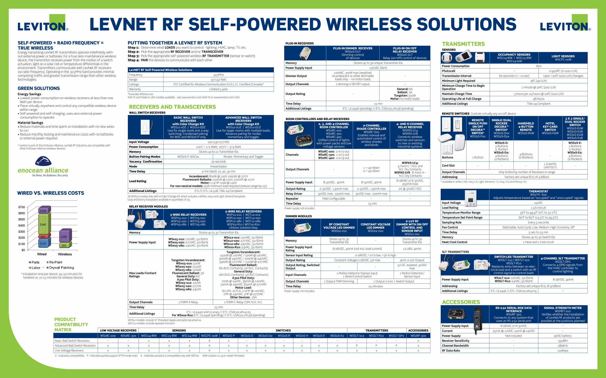
LEVNET RF SELF-POWERED WIRELESS SOLUTIONSSELF-POWERED + RADIO FREQUENCY = TRUE WIRELESSEnergy harvesting LevNet RF transmitters operate indefinitely with-out external power or batteries. For a true zero-maintenance wireless device, the transmitter receives power from the motion of a switch actuation, light on a solar cell or temperature differentials in the environment. Transmitters communicate with LevNet RF receivers via radio frequency. Operating in the 315MHz band provides minimal competing traffic and greater transmission range than other wireless technologies.
GREEN SOLUTIONSEnergy Savings• Lowest power consumption on wireless receivers at less than one
Watt per device• Place virtually anywhere and control any compatible wireless device
within range• Self-powered and self-charging, uses zero external power
consumption to operate
Material Savings• Reduce materials and time spent on installation with no new wires
to run• Reduce monthly testing and maintenance costs with no batteries
or external power required * Leviton is part of the EnOcean Alliance. LevNet RF Solutions are compatible with
other EnOcean Alliance wireless devices.
PUTTING TOGEThER A LEVNET RF SYSTEMStep 1: Determine what LOADS you want to control - lighting, HVAC, lamp, TV, etc.Step 2: Pick the appropriate RF RECEIVER and/or TRANSCEIVERStep 3: Pick the appropriate self-powered wireless RF TRANSMITTER (sensor or switch)Step 4: PAIR the devices to communicate with each other
DIMMER MODULES
RF CONSTANT VOLTAGE LED DIMMER
WSD02-010
CONSTANT VOLTAGE LED DIMMERWSD02-020
0-10V RF DIMMER WITh ON/OFF
CONTROL AND SENSOR INPUT
WSD01-001
Memory Stores up to 30 Transmitter IDs - Stores up to 30
Transmitter IDs
Power Supply Input Rating 8-28VDC, 40mA (not incl. load current) 12-28V, 40mA
Sensor Input Rating 0-28VDC, <1V is low, >3V is high
Output Rating Constant Voltage 0-28VDC, 5A max 4mA, 0-10V Output
Output Rating, Switched Output - - 5A DC, Isolated, 30VDC
max
Input Channels 1 Motion Detector/Sensor Input; 1 Wired Control Switch
1 Motion Detector/ Sensor Input
Output Channels 1 Output PWM Dimming 1 Output 0-10V, 1 Switch Output
Time Delay 15 minutes
Power supply not included.
REMOTE SWITChES Controls virtually any on/off device
REMOTE SINGLE PUSh
ON/OFF DECORA™ SWITCh*
WSS0S-P0x
SINGLE/DUAL ROCkER
DECORA™ SWITCh*
WSS0S-D0x WSS0S-D2x
hANDhELD 4-BUTTON
REMOTEWSS0S-R0W
hOTEL kEY CARD
SWITChWSS0S-H0W
3 x 3 SINGLE/DUAL ROCkER
SWITChWSS0S-E0W WSS0S-E0B WSS0S-E2W WSS0S-E2B
Buttons 1 Button
WSS0S-D: 2 Buttons (1 Rocker)
WSS0S-D2: 4 Buttons
(2 Rockers)
4 Buttons (2 Rockers) -
WSS0S-E: 2 Buttons (1 Rocker)
WSS0S-E2: 4 Buttons
(2 Rockers)
Card Slot - - - 1 (card IN, card OUT) -
Output Channels Only limited by number of Receivers in range
Addressing Factory set unique ID (1 of 4 billion)
* Available in white (-W), Ivory (-I), Light Almond (-T), Gray (-G) and Ebony (-E).
ThERMOSTAT WS0TH -S00
Adjusts temperature based on “occupied” and “unoccupied” signals
Input Voltage 24VAC
Load Rating 1.5A/circuit
Temperature Monitor Range 32°F to 99.9°F (0°C to 37.7°C)
Temperature Set Point Range 60°F to 85°F (15.5°C to 29.5°C)
Sampling Rule Every 5 seconds
Fan Control Selectable: Auto Cycle, Low, Medium, High, Economy, Off
Time Delay 5 sec to 15 min
Memory Stores up to 30 Switch IDs
Heat/Cool Control 1 Heat and 1 Cool circuit
SLT TRANSMITTERS
SWITCh LEG TRANSMITTERWSSLT-010 | WSTLT-010
WSSLT-R10Replaces wires between an elec-
trical load and a switch with an RF control signal to control loads
4-ChANNEL SLT TRANSMITTERWSSLT-GP0
Connects 4 GPIO signals from the HVAC controller to
control lighting
Power Supply Input WSxLT-010: 120VAC, 50/60HzWSSLT-R10: 24VAC, 50/60Hz 8-28VDC, 40mA
Addressing Factory set unique ID (1 of 4 billion)
Additional Listings ETL: UL244A, C-ETL: CSAc22.2#14-05 –
ACCESSORIESRS-232 SERIAL BOx DATA
INTERFACEWS0RF-300
Connects to any system that uses an RS-232 serial port
SIGNAL STRENGTh METERWSMET-010
Verifies whether the installation of LevNet RF products are
possible at the positions planned
Power Supply Input 8-28VAC or 8-30VDC -
Current 25mA @ 12VDC, 15mA @ 24VDC -
Power Supply Not included 9VDC battery
Receiver Sensitivity - -95dBm
Channel Bandwidth - 280kHz
RF Data Rate - 120kbps
LevNET RF Self-Powered Wireless Solutions
Frequency 315MHz
Range 50-150 feet
Listings FCC Certified for Wireless Communication (U.S.), I.C. Certified (Canada)*
Warranty Limited 5-year
*Excludes WSD02-020. NAFTA and Made in USA models available - visit www.leviton.com/NAFTA or www.leviton.com/USA.
RECEIVERS AND TRANSCEIVERSWALL SWITCh RECEIVERS
BASIC WALL SWITCh RECEIVERS
with Color Change kit WSS10-0DZ | WSS10-GDZ
Use for single loads and 3-way switching. Condensed pairing
for WSC and WSS0S-P only.
ADVANCED WALL SWITCh RECEIVERS
with Color Change kit WSS10-0UZ | WSS10-GUZ
Use for larger rooms with multiple loads. Advance pairing for rocker,
momentary and toggle.
Input Voltage 120-230-277VAC
Power Consumption 120V < 1/2 Watt; 277V < 3/4 Watt
Memory Stores up to 10 Transmitter IDs
Button Pairing Modes WSS0S-P, WSCxx Rocker, Momentary and Toggle
Vacancy Confirmation 30 seconds
Mode Presentation
Time Delay 2 min (test), 10, 20, 30 min
Load Rating
Incandescent: 800W @ 120V, 2000W @ 277VFluorescent Ballasts: 1200VA @ 120V, 2700VA @ 277V
Motor: 1/4 HP Load @ 120VFor non-neutral models: 25W minimum load required (reduce range by 15’)
Additional Listings ETL/C-ETL: UL508, Title 24 Compliant
RELAY RECEIVER MODULES
3-WIRE RELAY RECEIVERS WSP05-010 | WST05-010 WSP05-020 | WST05-020 WSP05-080 | WST05-080
5-WIRE RELAY RECEIVERS WSP12-010 | WST12-010 WSP12-020 | WST12-020 WSP12-080 | WST12-080 WSP02-R10 | WST02-R10
Utilizes isolated relay
Memory Stores up to 30 Transmitter IDs
Power Supply InputWSx05-010: 120VAC, 50/60HzWSx05-020: 277VAC, 50/60HzWSx05-080: 240VAC, 50/60Hz
WSx12-010: 120VAC, 50/60HzWSx12-020: 277VAC, 50/60HzWSx12-080: 240VAC, 50/60HzWSx02-R10: 24VAC, 50/60Hz
Max Loads/Contact Ratings
Tungsten/Incandescent: WSx05-010: 500W
WSx05-020: 1150W WSx05-080: 1000W
Fluorescent Ballast: 3A General Duty: 6A A300 Pilot Duty:
WSx05-010: 120VA WSx05-020: 277VA WSx05-080: 240VA
Tungsten/Incandescent: 1500W @ 120VAC / 500W @ 120VAC;
3000W @ 240VAC / 1000W @ 240VAC; 3400W @ 277VAC / 1100W @ 277VAC
Fluorescent Ballast: 8A (N.O. Contacts); 2A (N.C. Contacts)
General Duty: 16A (N.O. Contacts); 5A (N.C Contacts)
A300 Pilot Duty: 72VA @ 24VAC, 360VA @ 120VAC,
720VA @ 240VAC, 830VA @ 277VAC Motor Load:
60 LRA, 10 FLA, 1/2HP @ 120VAC, 1HP @ 240VAC, 1HP @ 277VAC
Other Devices: 16A
Output Channels 1 FORM A Relay 1 FORM C Relay COM, N.O., N.C.
Time Delay 15 min
Additional Listings ETL: UL244A and UL2043, C-ETL: CSAc22.2#14-05 For WSx02-R10: ETL: UL244A (pending), C-ETL: CSAc22.2#156 (pending)
TRANSMITTERSSENSORS
OCCUPANCY SENSORS WSC04-IRW | WSC15-IRW
WSC04-I0W
LIGhT SENSORSWSCPC-00W
Power Consumption Zero
Photocell - 0-94.8FC (0-1020 LUX)
Transmission Interval 60 seconds (+/- 10 sec) Upon >20FC (200 LUX) changes
Minimum Light Required 4FC (40 LUX)
Minimum Charge Time to Begin Operation 1 minute @ 20FC (200 LUX)
Maintain Charge Time 3 hours per 24 hours @ 20FC (200 LUX)
Operating Life at Full Charge 48 hours
Additional Listings Title 24 Compliant
PLUG-IN RECEIVERS
PLUG-IN DIMMER RECEIVERWSG0S-D1T
Dimming control of devices
PLUG-IN ON/OFF RELAY RECEIVER
WSG0S-S1T Relay (on/off) control of devices
Memory Stores up to 30 unique Transmitter IDs
Power Supply Input 120VAC, 60Hz
Dimmer Output120VAC, 300W max (resistive)
incandescent or other dimmable loads only – no motor loads
-
Output Channels 1 dimming or ON/OFF output -
Output Rating -
General: 6ABallast: 3A
Tungsten: 500WMotor: no motor loads
Time Delay 15 min
Additional Listings ETL: UL244A (pending), C-ETL: CSAc22.2#156 (pending)
WIRED VS. WIRELESS COSTS
* Installation time per device: 45-50 minutes for hardwire vs. 10-15 minutes for wireless devices
*
All WSS10 models ship with a Color Change Kit which includes a White, Ivory and Light Almond faceplate. Gray and Ebony faceplates available in quantities of 25.
WSTxx models: include ½” threaded nipple and external antennaWST12 models: include repeater function
LOW VOLTAGE RECEIVERS SENSORS SWITChES TRANSMITTERS ACCESSORIES
WS0RC-200 WS0RC-300 WSC04-IRW WSC15-IRW WSC04-IRW WSCPC-00W WSS0S-P WSS0S-D WSS0S-D2 WSS0S-R WSS0S-H WSS0S-E WSS0S-E2 WSSLT-010 WSSLT-R10 WSSLT-GP0 WS0RF-300
Basic Wall Switch Receivers - - x x x A x - - - - - - - - - x
Advanced Wall Switch Receivers x x x x x A x x x x x x x P P P x
Line Voltage Receivers x x x x x A x x x x x x x x x x x
PRODUCT COMPATIBILITY MATRIx
X - Indicates compatibility P - Indicates partial support (PTM mode only) A - Indicates product is compatible only with WSTxx With Leviton v1.19 or newer firmware

LEVNET RF QUICk SELECTION AND APPLICATION GUIDE
SERVICE AND SUPPORT DURING EVERY STEP OF ThE PROCESS. Only Leviton has the service and support to help you create a lighting control system that does exactly what you want it to do while saving electricity, meeting codes and standards, and even garnering rebates.
ExCLUSIVE WEALTh OF RESOURCES:
• Occupancy sensor layout services – have a team of experts create occupancy sensor layouts at no cost to you directly on your CAD drawings, complete with a List of Equipment within an average turnaround time of 3 business days* – go to portal.leviton.com
• Dollars & Sensors – get an accurate estimate of your energy-savings potential with this exclusive payback analysis tool
• ez-Learn – get sensor smart in just 90 minutes from the comfort of your home or office with this exclusive 24/7 online training
• Lighting control specialists at your disposal
• Field service engineers for top-level support
• Factory commissioning service
• Dedicated technical support via phone at 800-824-3005
* Average turnaround time based on projects for up to 200 sensors per system.
Leviton Manufacturing Co., Inc. Lighting & Energy Solutions201 N. Service Rd. Melville, NY 11747-3138 Tech Line: 1-800-824-3005 • FAX: 1-800-832-9538 • www.leviton.com/les
Leviton Manufacturing of Canada, Ltd.165 Hymus Boulevard, Pointe Claire, Quebec H9R 1E9 Telephone: 1-800-469-7890 • FAX: 1-800-563-1853
Leviton S. de R.L. de C.V.Lago Tana 43, Mexico DF, Mexico CP 11290 Tel. (+52) 55-5082-1040 • FAX: (+52) 5386-1797 • www.leviton.com.mx
Visit our Website at: www.leviton.com/les© 2011 Leviton Manufacturing Co., Inc. All rights reserved. Subject to change without notice.G-8431A/A11-akREV JAN 2011
hOW TO PUT IT ALL TOGEThERTIP: A good way to visualize your wireless system is to imagine that the “wires” connecting each device are invisible wires or “unique addresses.”
LevNet RF Wireless/Wired-In Receivers
Receives One Way Communication
BASIC WALL SWITCh RECEIVER PAIRINGStep 1: Enter Pairing• Press & hold button for 15 seconds• LED will change to flashing amberStep 2: Select Pairing or Clear ModeFor Basic WSS10 Models• Amber LED (1 flash = Pairing; 2 flashes = Clear)• No devices can be paired on flashing amber, continue to step 3 unless you need to CLEARFor Advanced WSS10 Models• Amber LED (1 flash = Rocker; 2 flashes = Momentary, 3 flashes = Toggle, 4 flashes = Scene, 5 flashes = Clear)• Select pairing mode by tapping button to advance flashes• No devices can be paired on flashing amber, continue to step 3 unless you need to CLEARStep 3: Enter the Pairing Mode• Press & hold button for 5 seconds• LED will change to red (no devices paired) or green (number of flashes indicates number of devices paired)For Advanced WSS10 Models• Tap button to return to mode selection (amber LED)Step 4: Pair Transmitter Button• Tap the button you wish to pair• LED will hold amber & then flash green acknowledging successful pairingStep 5: Exit Pairing• Auto exit will occur in 20 seconds
RELAY RECEIVERS WITh 2-BUTTON PAIRINGStep 1: Enter Pairing• Press & hold LRN until load flashesStep 2: Select Pairing Mode• Press & hold LRN button again to advance modes (1 flash = Rocker; 2 flashes = Momentary; 3 flashes = Toggle)• Load will flash faster to acknowledgeStep 3: Pair Transmitter Button• Press & release the button you wish to pair• Load will hold ON for successful pairing, hold OFF for unpairingStep 4: Exit Pairing• Auto exit will occur in 30 seconds, or• Press LRN for 2 seconds and release
ROOM CONTROLLER TRANSCEIVER PAIRINGStep 1: Enter Pairing (Output 1)• Press & hold LRN until load 1 starts flashingStep 2: Select Pairing Mode• Press & hold LRN button again to advance modes (1 flash = Rocker; 2 flashes = Momentary; 3 flashes = Toggle)• Load will flash faster to acknowledge next modeStep 3: Pair Transmitter Button• Press & release the button you wish to pair• Load will hold ON for successful pairing, hold OFF for unpairingStep 4: Enter Pairing (Additional Outputs)• Press/release the LRN button• LED will flash 2x for output 2, 3x for output 3• Repeat steps 2 & 3 for each output Step 5: Exit Pairing• Wait 30 seconds• Press LRN for 2 seconds and release
LRNCLR
LRNCLR
Output LED
LRNCLR
BASIC LEVNET RF SOLUTIONS
OR
Plug-In ON/OFFRelay Receiver
WirelessSwitches
WirelessControl SignalUp To 150 ft.
Basic Wireless Lighting
Wireless Remote Switch
Wall SwitchReceiver
WirelessControl SignalUp To 150 ft.
Lighting
3-Way or Multi-Location Switching
Contact your Leviton representative for additional smart energy saving solutions to expand and upgrade your system.
LEVNET RFTRANSMITTERS
WirelessOccupancy Sensor
Wireless 3 x 3 Switches
Wireless Switches
4-Button Handheld Remote
Hotel Key Card Switch
LEVNET RFRECEIVERS
Thermostat
5-WireRelay Receiver
Plug-In ON/OFFRelay Receiver
Plug-In ON/OFFRelay Receiver
24V 5-WireRelay Receiver
Television
LOADS
Lighting
HVAC Unit
Fan
WirelessControl SignalUp To 150 ft.
One Way Communication
LevNet RF Self-Powered Wireless Transmitters
STEP1
STEP2
STEP3
Determine what LOADS you want to control — lighting, hVAC, lamp, TV, etc.
Pick the appropriate RF RECEIVER and/or TRANSCEIVER
Pick the appropriate Self-Powered Wireless RF TRANSMITTER (sensor or switch)
STEP4
PAIR the devices to communicate with each other
LevNet RF Self-Powered Wireless Solutions Product Guide
LevNet RF Wireless/Wired-In Transceivers
Receiver Transmitter
Repeater
WirelessControl SignalUp To 150 ft.
Lighting
Wireless Dual Rocker
Switch
3-Wire Relay Receiver
3-Wire Relay Receiver
WirelessLight Sensor
Daylight harvesting with Bi-Level Control
WirelessControl SignalUp To 150 ft.
LightingWirelessOccupancy
Sensor
Wall SwitchReceiver
Wall SwitchReceiver
Occupancy Sensor with Bi-Level Control
Hotel Key Card Switch
ThermostatHVAC Unit
WirelessControl SignalUp To 150 ft.
Lighting
Wall SwitchReceiver
hospitality Application


![Brochure2 - MagicBricks€¦ · Location Map School B sc Delhi Pub licSçh001 To 20 min 13 12 min 10 min 08 m] n 02 Temple AFMC 20 min 12 min IS min 10 min min IS min min 07 min](https://img.pdfslide.us/doc/110x75/6034384eb5808f20db6ba851/brochure2-magicbricks-location-map-school-b-sc-delhi-pub-licsh001-to-20-min.jpg)