Embed Size (px)
Citation preview
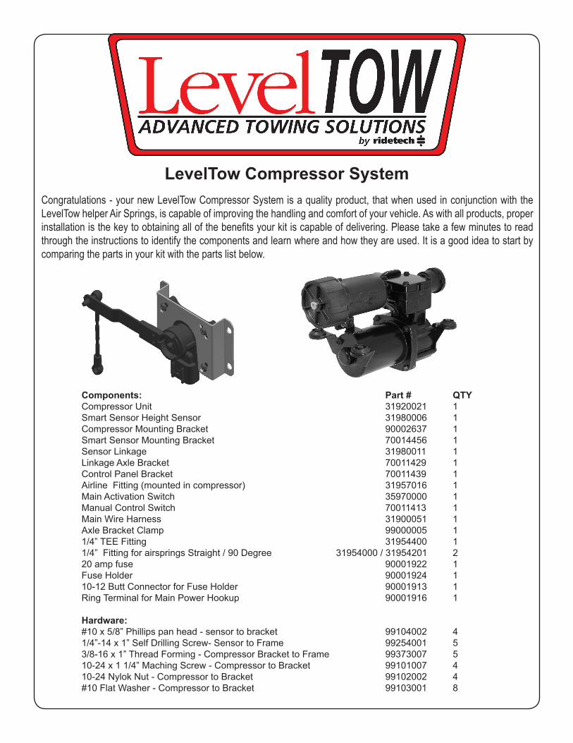
LevelTow Compressor SystemCongratulations - your new LevelTow Compressor System is a quality product, that when used in conjunction with the LevelTow helper Air Springs, is capable of improving the handling and comfort of your vehicle. As with all products, proper installation is the key to obtaining all of the benefi ts your kit is capable of delivering. Please take a few minutes to read through the instructions to identify the components and learn where and how they are used. It is a good idea to start by comparing the parts in your kit with the parts list below.
Components: Part # QTY Compressor Unit 31920021 1 Smart Sensor Height Sensor 31980006 1 Compressor Mounting Bracket 90002637 1 Smart Sensor Mounting Bracket 70014456 1 Sensor Linkage 31980011 1 Linkage Axle Bracket 70011429 1 Control Panel Bracket 70011439 1 Airline Fitting (mounted in compressor) 31957016 1 Main Activation Switch 35970000 1 Manual Control Switch 70011413 1 Main Wire Harness 31900051 1 Axle Bracket Clamp 99000005 1 1/4” TEE Fitting 31954400 1 1/4” Fitting for airsprings Straight / 90 Degree 31954000 / 31954201 2 20 amp fuse 90001922 1 Fuse Holder 90001924 1 10-12 Butt Connector for Fuse Holder 90001913 1 Ring Terminal for Main Power Hookup 90001916 1
Hardware: #10 x 5/8” Phillips pan head - sensor to bracket 99104002 4 1/4”-14 x 1” Self Drilling Screw- Sensor to Frame 99254001 5 3/8-16 x 1” Thread Forming - Compressor Bracket to Frame 99373007 5 10-24 x 1 1/4” Maching Screw - Compressor to Bracket 99101007 4 10-24 Nylok Nut - Compressor to Bracket 99102002 4 #10 Flat Washer - Compressor to Bracket 99103001 8
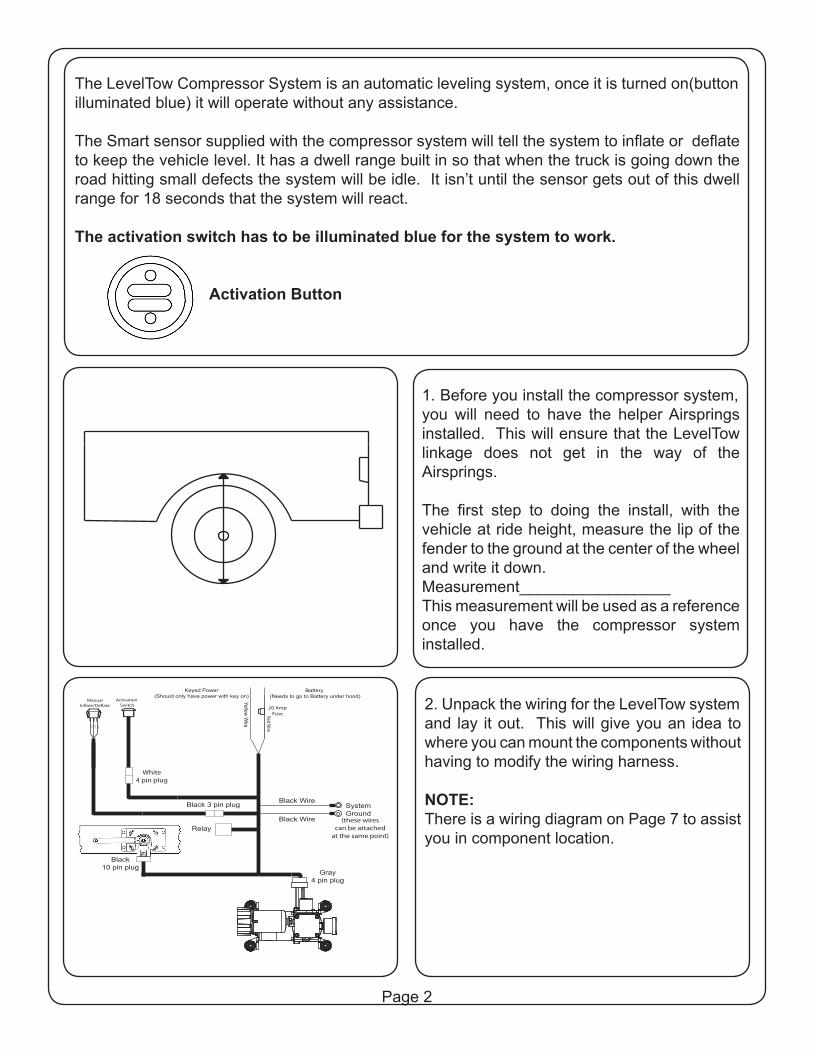
The LevelTow Compressor System is an automatic leveling system, once it is turned on(button illuminated blue) it will operate without any assistance.
The Smart sensor supplied with the compressor system will tell the system to infl ate or defl ate to keep the vehicle level. It has a dwell range built in so that when the truck is going down the road hitting small defects the system will be idle. It isn’t until the sensor gets out of this dwell range for 18 seconds that the system will react.
The activation switch has to be illuminated blue for the system to work.
Activation Button
1. Before you install the compressor system, you will need to have the helper Airsprings installed. This will ensure that the LevelTow linkage does not get in the way of the Airsprings.
The fi rst step to doing the install, with the vehicle at ride height, measure the lip of the fender to the ground at the center of the wheel and write it down.Measurement_________________This measurement will be used as a reference once you have the compressor system installed.
2. Unpack the wiring for the LevelTow system and lay it out. This will give you an idea to where you can mount the components without having to modify the wiring harness.
NOTE:There is a wiring diagram on Page 7 to assist you in component location.
RedW
ire
20 AmpFuse
Activation Switch
ManualIn�ate/De�ate
GREEN
BLACK
BLUE
White4 pin plug
Black10 pin plug
Gray4 pin plug
Relay
Black 3 pin plug Black Wire
Black Wire
SystemGround
YellowW
ire
Battery (Needs to go to Battery under hood)
Keyed Power(Should only have power with key on)
(these wirescan be attached
at the same point)
Page 2
Activation Button
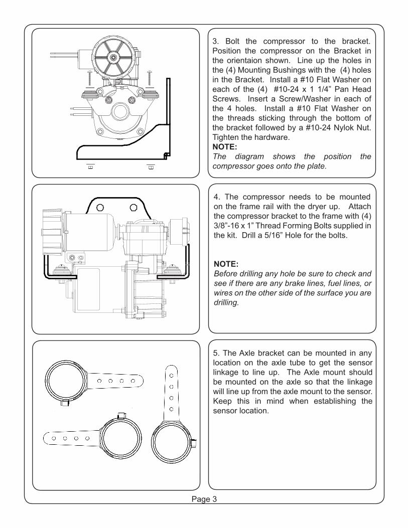
3. Bolt the compressor to the bracket. Position the compressor on the Bracket in the orientaion shown. Line up the holes in the (4) Mounting Bushings with the (4) holes in the Bracket. Install a #10 Flat Washer on each of the (4) #10-24 x 1 1/4” Pan Head Screws. Insert a Screw/Washer in each of the 4 holes. Install a #10 Flat Washer on the threads sticking through the bottom of the bracket followed by a #10-24 Nylok Nut. Tighten the hardware.NOTE:The diagram shows the position the compressor goes onto the plate.
4. The compressor needs to be mounted on the frame rail with the dryer up. Attach the compressor bracket to the frame with (4) 3/8”-16 x 1” Thread Forming Bolts supplied in the kit. Drill a 5/16” Hole for the bolts.
NOTE:Before drilling any hole be sure to check and see if there are any brake lines, fuel lines, or wires on the other side of the surface you are drilling.
5. The Axle bracket can be mounted in any location on the axle tube to get the sensor linkage to line up. The Axle mount should be mounted on the axle so that the linkage will line up from the axle mount to the sensor. Keep this in mind when establishing the sensor location.
Page 3
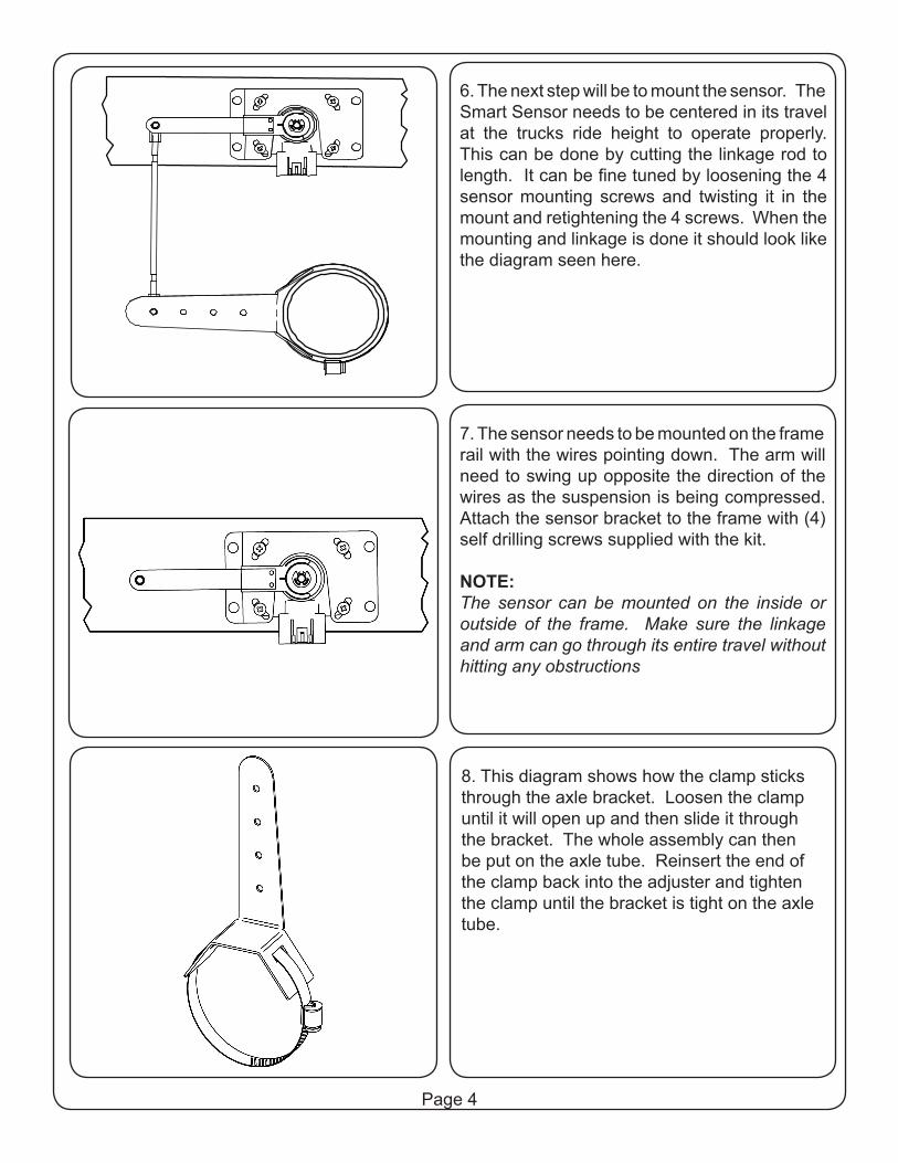
6. The next step will be to mount the sensor. The Smart Sensor needs to be centered in its travel at the trucks ride height to operate properly. This can be done by cutting the linkage rod to length. It can be fine tuned by loosening the 4 sensor mounting screws and twisting it in the mount and retightening the 4 screws. When the mounting and linkage is done it should look like the diagram seen here.
7. The sensor needs to be mounted on the frame rail with the wires pointing down. The arm will need to swing up opposite the direction of the wires as the suspension is being compressed. Attach the sensor bracket to the frame with (4) self drilling screws supplied with the kit.
NOTE:The sensor can be mounted on the inside or outside of the frame. Make sure the linkage and arm can go through its entire travel without hitting any obstructions
8. This diagram shows how the clamp sticks through the axle bracket. Loosen the clamp until it will open up and then slide it through the bracket. The whole assembly can then be put on the axle tube. Reinsert the end of the clamp back into the adjuster and tighten the clamp until the bracket is tight on the axle tube.
Page 4
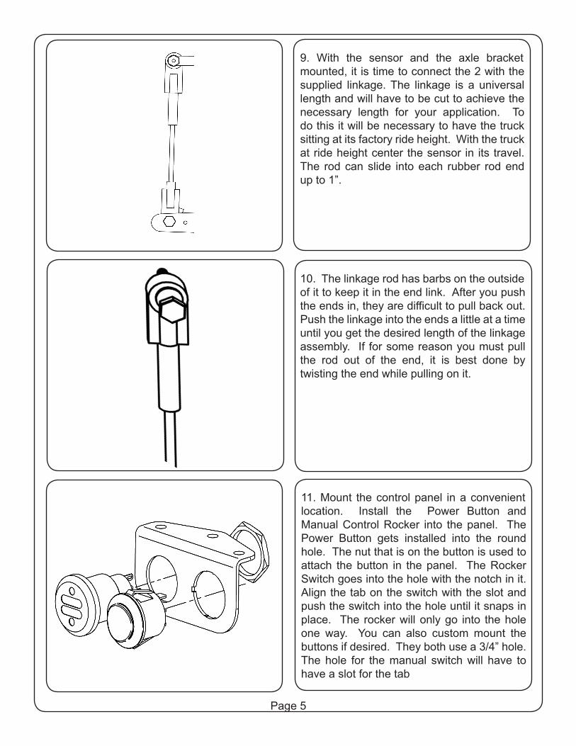
9. With the sensor and the axle bracket mounted, it is time to connect the 2 with the supplied linkage. The linkage is a universal length and will have to be cut to achieve the necessary length for your application. To do this it will be necessary to have the truck sitting at its factory ride height. With the truck at ride height center the sensor in its travel. The rod can slide into each rubber rod end up to 1”.
10. The linkage rod has barbs on the outside of it to keep it in the end link. After you push the ends in, they are diffi cult to pull back out. Push the linkage into the ends a little at a time until you get the desired length of the linkage assembly. If for some reason you must pull the rod out of the end, it is best done by twisting the end while pulling on it.
11. Mount the control panel in a convenient location. Install the Power Button and Manual Control Rocker into the panel. The Power Button gets installed into the round hole. The nut that is on the button is used to attach the button in the panel. The Rocker Switch goes into the hole with the notch in it. Align the tab on the switch with the slot and push the switch into the hole until it snaps in place. The rocker will only go into the hole one way. You can also custom mount the buttons if desired. They both use a 3/4” hole. The hole for the manual switch will have to have a slot for the tab
Page 5
RedW
ire
20 AmpFuse
Activation Switch
ManualIn�ate/De�ate
GREEN
BLACK
BLUE
White4 pin plug
Black10 pin plug
Gray4 pin plug
Relay
Black 3 pin plug Black Wire
Black Wire
SystemGround
YellowW
ire
Battery (Needs to go to Battery under hood)
Keyed Power(Should only have power with key on)
(these wirescan be attached
at the same point)
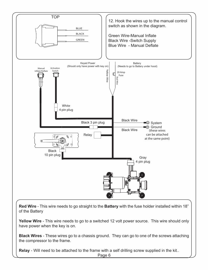
Red Wire - This wire needs to go straight to the Battery with the fuse holder installed within 18” of the Battery
Yellow Wire - This wire needs to go to a switched 12 volt power source. This wire should only have power when the key is on.
Black Wires - These wires go to a chassis ground. They can go to one of the screws attaching the compressor to the frame.
Relay - Will need to be attached to the frame with a self drilling screw supplied in the kit..
12. Hook the wires up to the manual control switch as shown in the diagram.
Green Wire-Manual Infl ateBlack Wire -Switch SupplyBlue Wire - Manual Defl ate
Page 6
GREEN
BLACK
BLUE
TOP
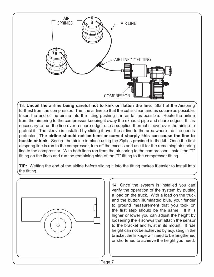
14. Once the system is installed you can verify the operation of the system by putting a load on the truck. With a load on the truck and the button illuminated blue, your fender to ground measurement that you took on the first step should be the same. If it is higher or lower you can adjust the height by loosening the 4 screws that attach the sensor to the bracket and twist in its mount. If ride height can not be achieved by adjusting in the bracket the linkage will need to be lengthened or shortened to achieve the height you need.
Page 7
AIR LINEAIR
SPRINGS
COMPRESSOR
AIR LINE “T” FITTING
13. Uncoil the airline being careful not to kink or flatten the line. Start at the Airspring furthest from the compressor. Trim the airline so that the cut is clean and as square as possible. Insert the end of the airline into the fitting pushing it in as far as possible. Route the airline from the airspring to the compressor keeping it away the exhaust pipe and sharp edges. If it is necessary to run the line over a sharp edge, use a supplied thermal sleeve over the airline to protect it. The sleeve is installed by sliding it over the airline to the area where the line needs protected. The airline should not be bent or curved sharply, this can cause the line to buckle or kink. Secure the airline in place using the Zipties provided in the kit. Once the first airspring line is ran to the compressor, trim off the excess and use it for the remaining air spring line to the compressor. With both lines ran from the air spring to the compressor, install the “T” fitting on the lines and run the remaining side of the “T” fitting to the compressor fitting.
TIP: Wetting the end of the airline before sliding it into the fitting makes it easier to install into the fitting.
Manual Operation:The LevelTow Compressor System also has a manual control function. This function allows you to manually infl ated or defl ate the system. To use the manual function you must fi rst turn the system off by pushing the main power button. Once the system is turned off you can push the rocker switch up to infl ate or down to defl ate. To put the system back in level mode push the main power switch to turn it back on.
Note:If the Activation Button is illuminated blue and the manual button is pushed the truck will relevel itself. The activation button has to be off for the manual control to be used and the truck remain at the height.
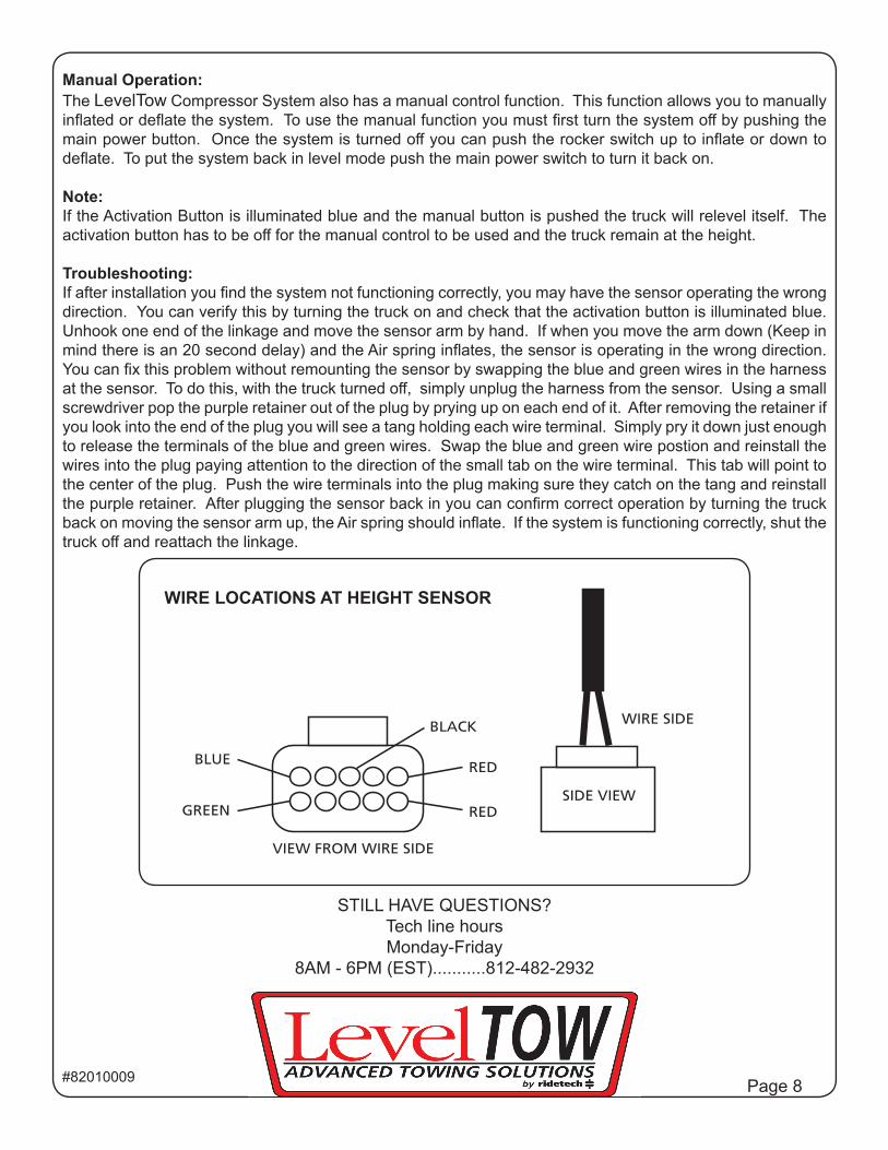
Troubleshooting:If after installation you fi nd the system not functioning correctly, you may have the sensor operating the wrong direction. You can verify this by turning the truck on and check that the activation button is illuminated blue. Unhook one end of the linkage and move the sensor arm by hand. If when you move the arm down (Keep in mind there is an 20 second delay) and the Air spring infl ates, the sensor is operating in the wrong direction. You can fi x this problem without remounting the sensor by swapping the blue and green wires in the harness at the sensor. To do this, with the truck turned off , simply unplug the harness from the sensor. Using a small screwdriver pop the purple retainer out of the plug by prying up on each end of it. After removing the retainer if you look into the end of the plug you will see a tang holding each wire terminal. Simply pry it down just enough to release the terminals of the blue and green wires. Swap the blue and green wire postion and reinstall the wires into the plug paying attention to the direction of the small tab on the wire terminal. This tab will point to the center of the plug. Push the wire terminals into the plug making sure they catch on the tang and reinstall the purple retainer. After plugging the sensor back in you can confi rm correct operation by turning the truck back on moving the sensor arm up, the Air spring should infl ate. If the system is functioning correctly, shut the truck off and reattach the linkage.
STILL HAVE QUESTIONS?Tech line hoursMonday-Friday
8AM - 6PM (EST)...........812-482-2932
Page 8#82010009
RED
RED
BLACK
BLUE
GREEN
VIEW FROM WIRE SIDE
WIRE SIDE
SIDE VIEW
WIRE LOCATIONS AT HEIGHT SENSOR