Embed Size (px)
Citation preview
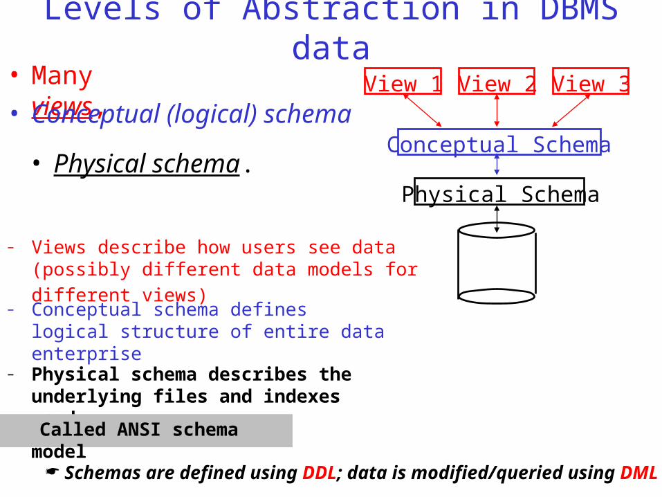
Levels of Abstraction in DBMS data
Schemas are defined using DDL; data is modified/queried using DML.
– Views describe how users see data (possibly different data models for different views)
• Many views, View 1 View 2 View 3
Conceptual Schema• Conceptual (logical) schema
Physical Schema• Physical schema.
– Conceptual schema defines logical structure of entire data enterprise
– Physical schema describes the underlying files and indexes used.
Called ANSI schema model
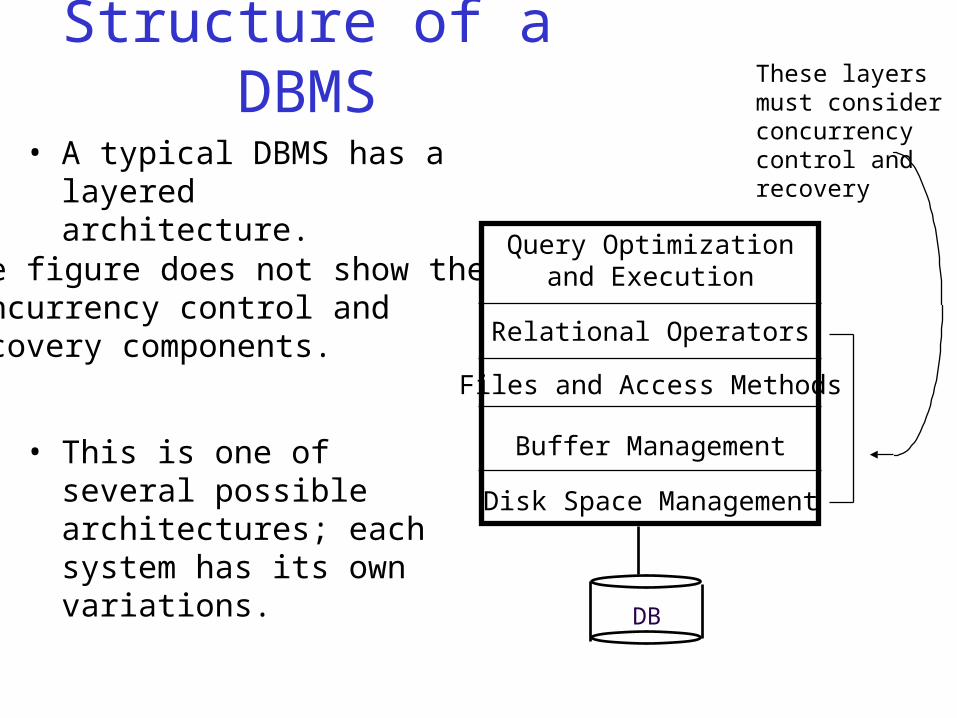
Structure of a DBMS
• A typical DBMS has a layered architecture.
Query Optimizationand Execution
Relational Operators
Files and Access Methods
Buffer Management
Disk Space Management
DB
These layersmust considerconcurrencycontrol andrecovery
• This is one of several possible architectures; each system has its own variations.
The figure does not show theconcurrency control andrecovery components.
Overview of Database Design
• Conceptual design: (ER Model is used at this stage.)
– What are the entities and relationships in the enterprise?
– What information about these entities and relationships should we store in the database?
– What integrity constraints or business rules hold?
– A database `schema’ in the ER Model can be represented pictorially (ER diagrams).
– Then we can map an ER diagram into a relational schema.
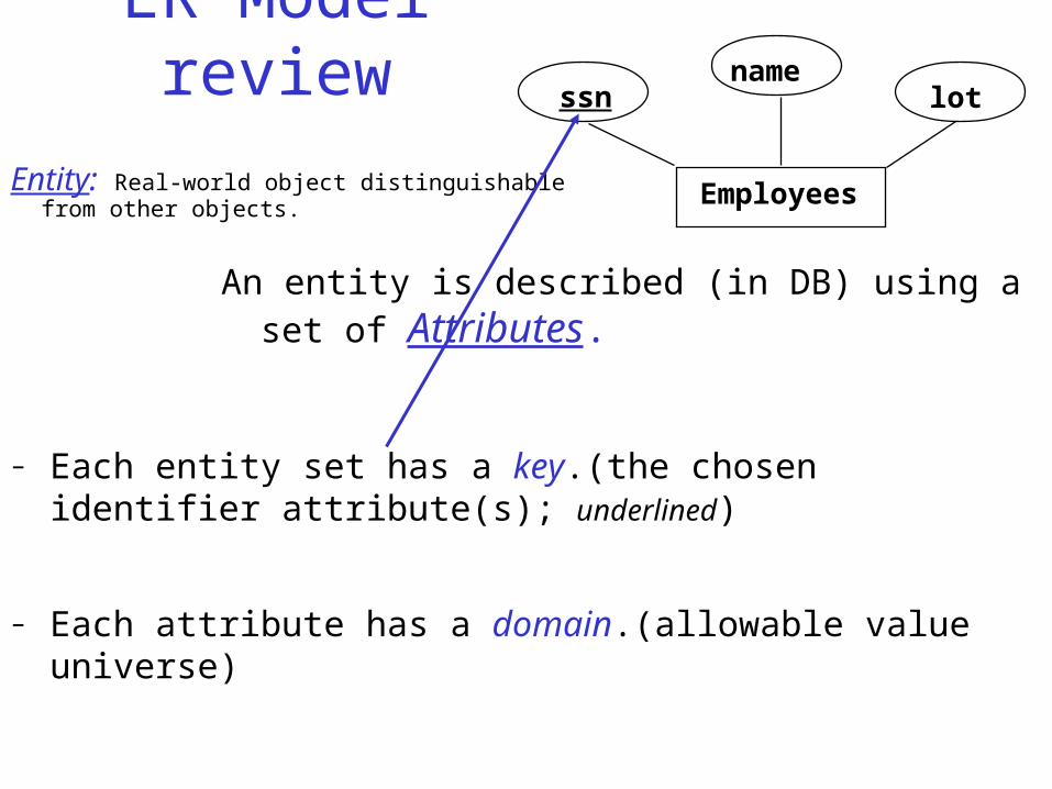
ER Model review
Entity: Real-world object distinguishable from other objects.
Employees
– Each entity set has a key.(the chosen identifier attribute(s); underlined)
ssnname
lot
An entity is described (in DB) using a set of Attributes.
– Each attribute has a domain.(allowable value universe)
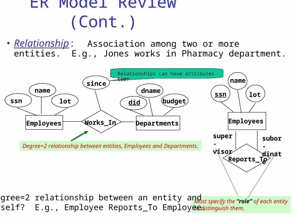
ER Model Review (Cont.)
• Relationship: Association among two or more entities. E.g., Jones works in Pharmacy department.
lot
name
Employees
ssn
since
Works_In
dname
budgetdid
Departments
Degree=2 relationship between entities, Employees and Departments.subor-dinate
super-visor
Reports_To
lot
name
Employees
ssn
Must specify the “role” of each entityto distinguish them.
Degree=2 relationship between an entity andItself? E.g., Employee Reports_To Employee.
Relationships can have attributes too!
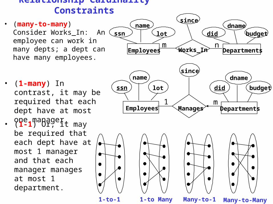
Relationship Cardinality Constraints
• (many-to-many) Consider Works_In: An employee can work in many depts; a dept can have many employees.
1-to-1 1-to Many Many-to-1 Many-to-Many
• (1-many) In contrast, it may be required that each dept have at most one manager.
dname
budgetdid
since
lot
name
ssn
ManagesEmployees Departments1 m
lotdname
budgetdid
sincename
Works_In DepartmentsEmployees
ssn
m n
• (1-1) Or, it may be required that each dept have at most 1 manager and that each manager manages at most 1 department.
Database Design I: The Entity-Relationship Model
Chapter 5
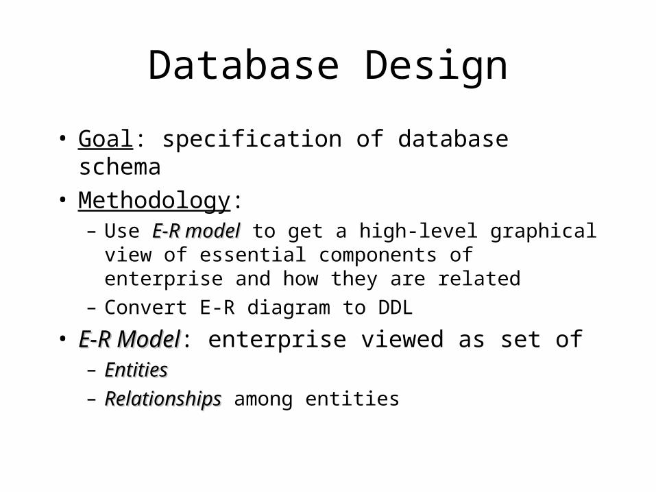
Database Design
• Goal: specification of database schema• Methodology:
– Use E-R modelE-R model to get a high-level graphical view of essential components of enterprise and how they are related
– Convert E-R diagram to DDL
• E-R ModelE-R Model: enterprise viewed as set of– EntitiesEntities
– RelationshipsRelationships among entities
Entities
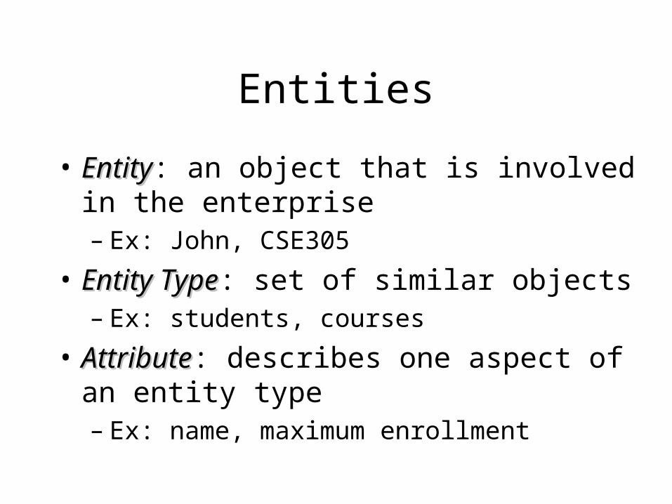
• EntityEntity: an object that is involved in the enterprise– Ex: John, CSE305
• Entity TypeEntity Type: set of similar objects– Ex: students, courses
• AttributeAttribute: describes one aspect of an entity type– Ex: name, maximum enrollment
Entity Type
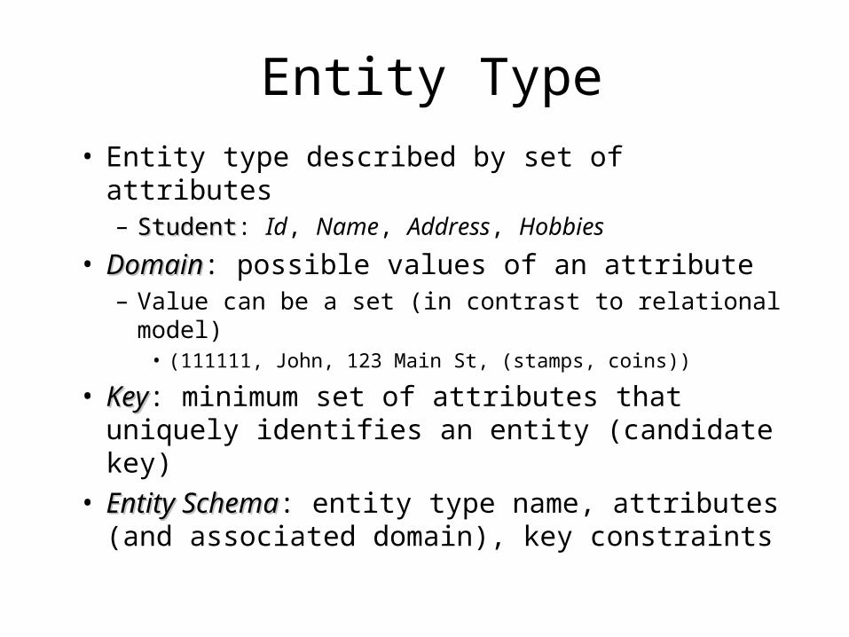
• Entity type described by set of attributes– StudentStudent: Id, Name, Address, Hobbies
• DomainDomain: possible values of an attribute– Value can be a set (in contrast to relational model)
• (111111, John, 123 Main St, (stamps, coins))
• KeyKey: minimum set of attributes that uniquely identifies an entity (candidate key)
• Entity SchemaEntity Schema: entity type name, attributes (and associated domain), key constraints
Representation in Relational Model
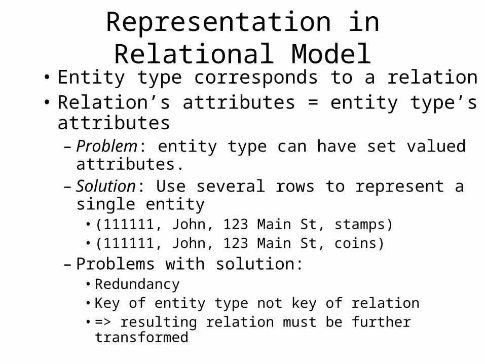
• Entity type corresponds to a relation• Relation’s attributes = entity type’s attributes
– Problem: entity type can have set valued attributes. – Solution: Use several rows to represent a single
entity• (111111, John, 123 Main St, stamps)• (111111, John, 123 Main St, coins)
– Problems with solution:• Redundancy• Key of entity type not key of relation• => resulting relation must be further transformed
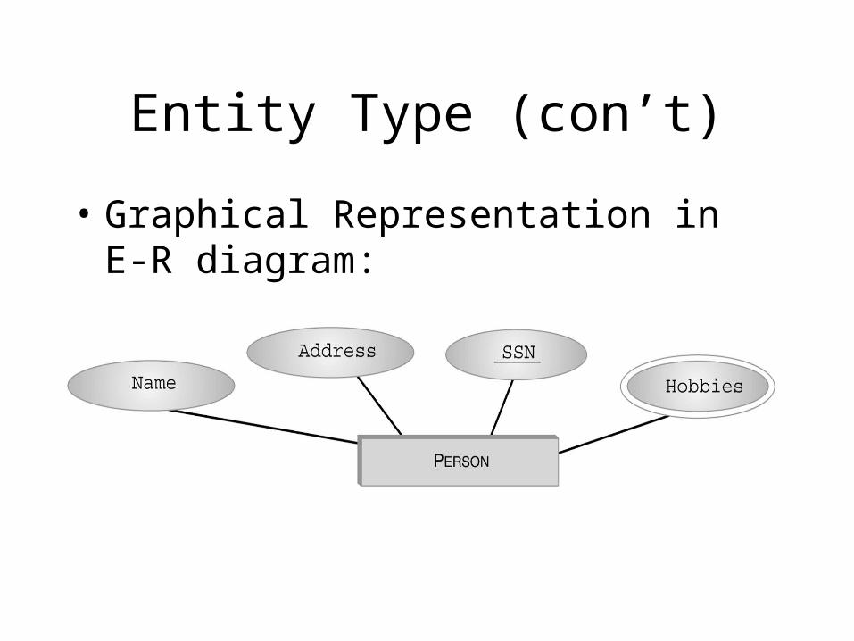
Entity Type (con’t)
• Graphical Representation in E-R diagram:
Relationship
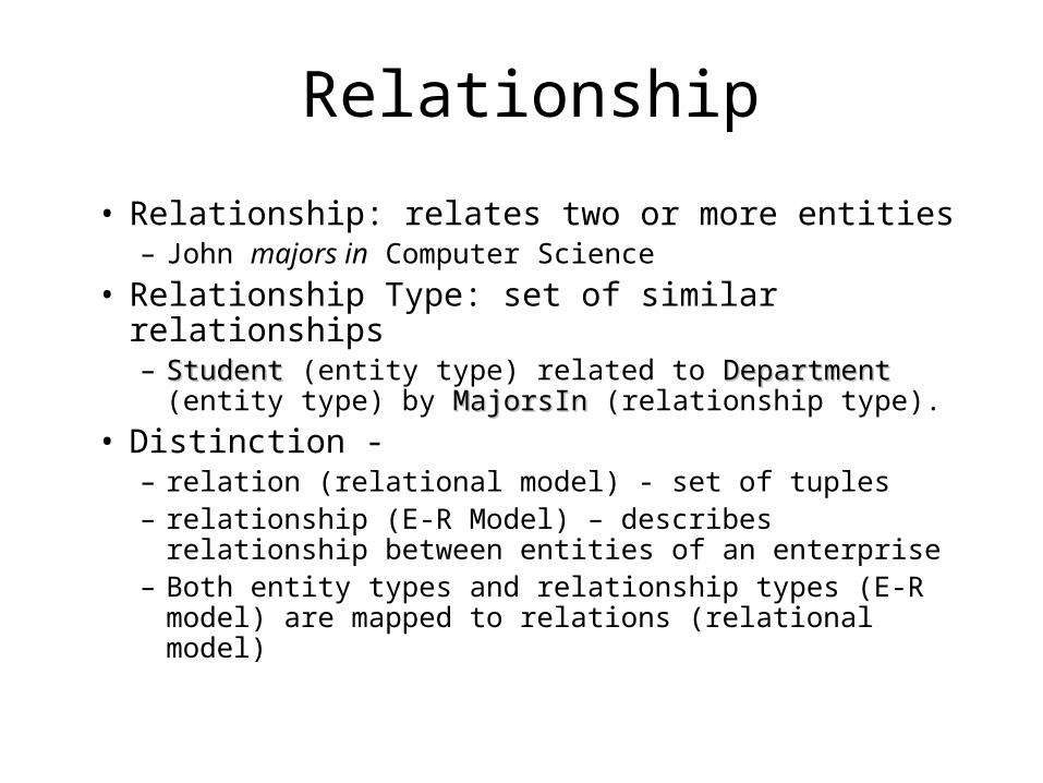
• Relationship: relates two or more entities– John majors in Computer Science
• Relationship Type: set of similar relationships– StudentStudent (entity type) related to DepartmentDepartment (entity type)
by MajorsInMajorsIn (relationship type).
• Distinction - – relation (relational model) - set of tuples– relationship (E-R Model) – describes relationship
between entities of an enterprise– Both entity types and relationship types (E-R model)
are mapped to relations (relational model)
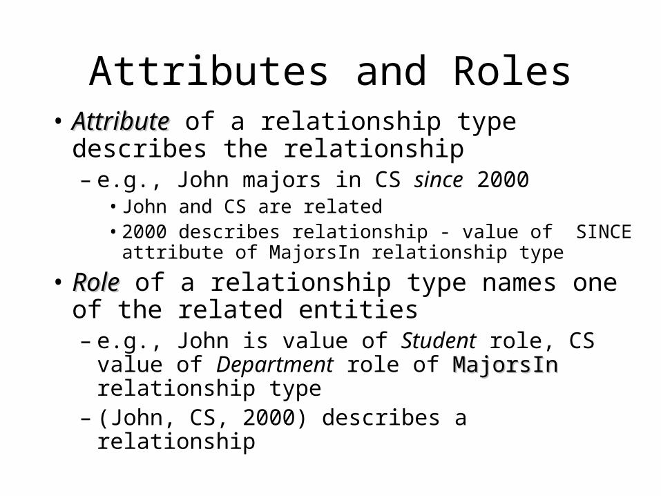
Attributes and Roles• AttributeAttribute of a relationship type describes the
relationship– e.g., John majors in CS since 2000
• John and CS are related• 2000 describes relationship - value of SINCE attribute
of MajorsIn relationship type
• RoleRole of a relationship type names one of the related entities– e.g., John is value of Student role, CS value of
Department role of MajorsInMajorsIn relationship type– (John, CS, 2000) describes a relationship
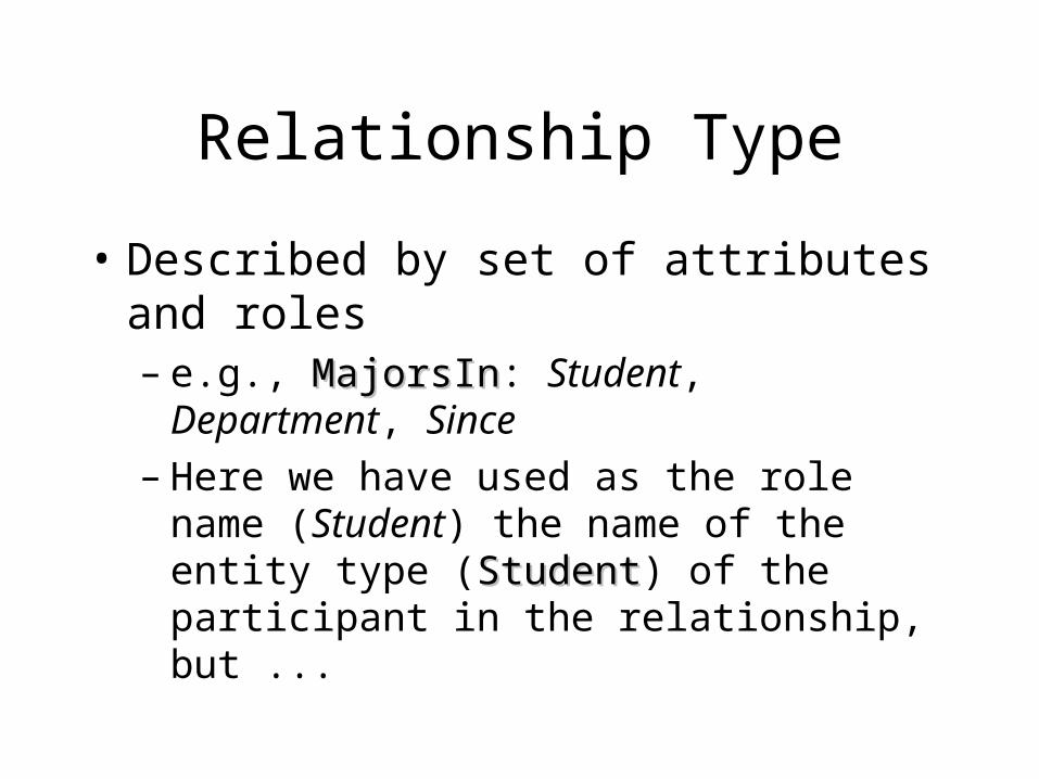
Relationship Type
• Described by set of attributes and roles– e.g., MajorsInMajorsIn: Student, Department, Since– Here we have used as the role name (Student)
the name of the entity type (StudentStudent) of the participant in the relationship, but ...
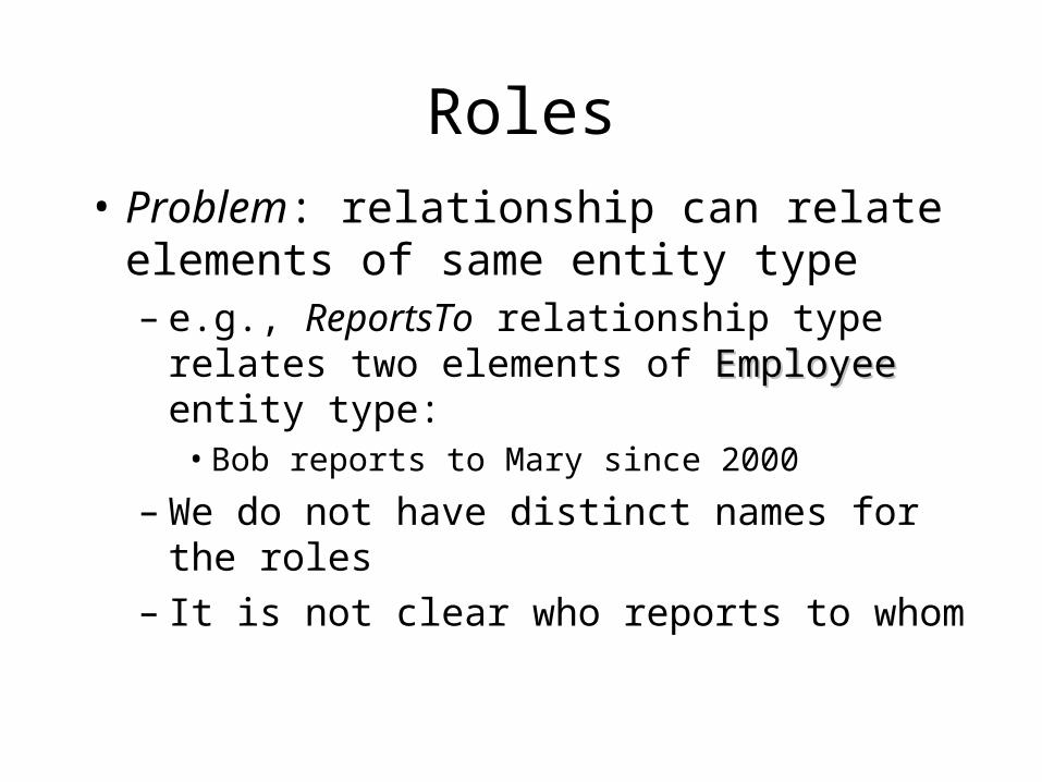
Roles
• Problem: relationship can relate elements of same entity type– e.g., ReportsTo relationship type relates two
elements of EmployeeEmployee entity type: • Bob reports to Mary since 2000
– We do not have distinct names for the roles– It is not clear who reports to whom
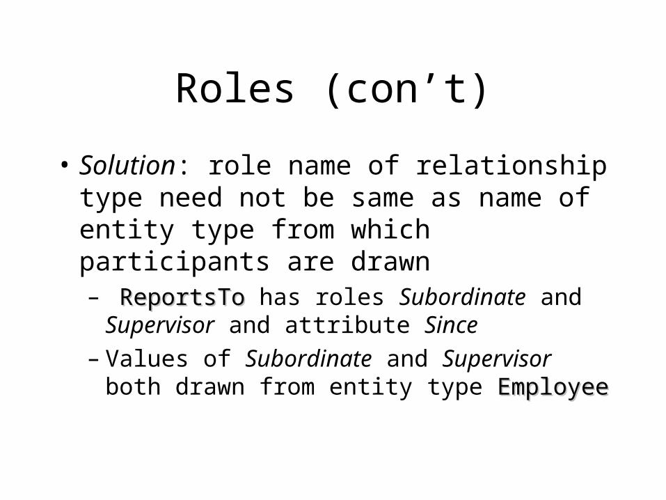
Roles (con’t)
• Solution: role name of relationship type need not be same as name of entity type from which participants are drawn– ReportsToReportsTo has roles Subordinate and
Supervisor and attribute Since– Values of Subordinate and Supervisor both
drawn from entity type EmployeeEmployee
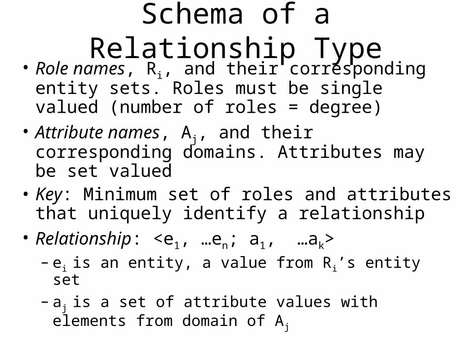
Schema of a Relationship Type• Role names, Ri, and their corresponding entity
sets. Roles must be single valued (number of roles = degree)
• Attribute names, Aj, and their corresponding domains. Attributes may be set valued
• Key: Minimum set of roles and attributes that uniquely identify a relationship
• Relationship: <e1, …en; a1, …ak>– ei is an entity, a value from Ri’s entity set– aj is a set of attribute values with elements from
domain of Aj
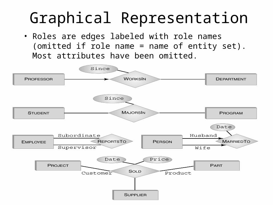
Graphical Representation• Roles are edges labeled with role names (omitted if role name
= name of entity set). Most attributes have been omitted.
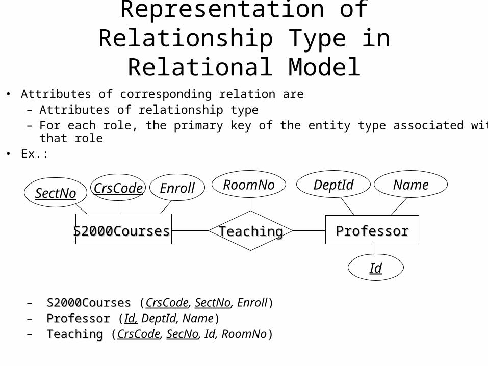
Representation of Relationship Type in Relational Model
• Attributes of corresponding relation are– Attributes of relationship type– For each role, the primary key of the entity type associated with that role
• Ex.:
– S2000CoursesS2000Courses (CrsCode, SectNo, Enroll)– ProfessorProfessor (Id, DeptId, Name)– TeachingTeaching (CrsCode, SecNo, Id, RoomNo)
TeachingTeachingS2000CoursesS2000Courses ProfessorProfessor
DeptId NameRoomNoCrsCode EnrollSectNo
Id
Representation in Relational Model
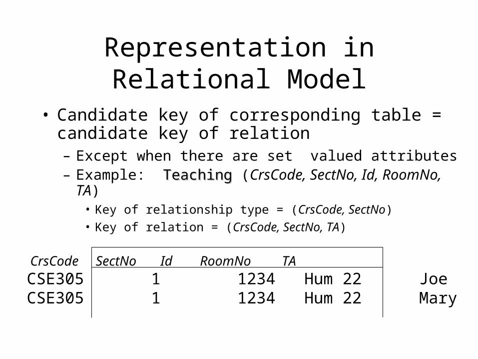
• Candidate key of corresponding table = candidate key of relation– Except when there are set valued attributes– Example: TeachingTeaching (CrsCode, SectNo, Id, RoomNo, TA)
• Key of relationship type = (CrsCode, SectNo)
• Key of relation = (CrsCode, SectNo, TA)
CrsCode SectNo Id RoomNo TA
CSE305 1 1234 Hum 22 JoeCSE305 1 1234 Hum 22 Mary
Representation in SQL
• Each role of relationship type produces a foreign key in corresponding relation– Foreign key references table corresponding to
entity type from which role values are drawn
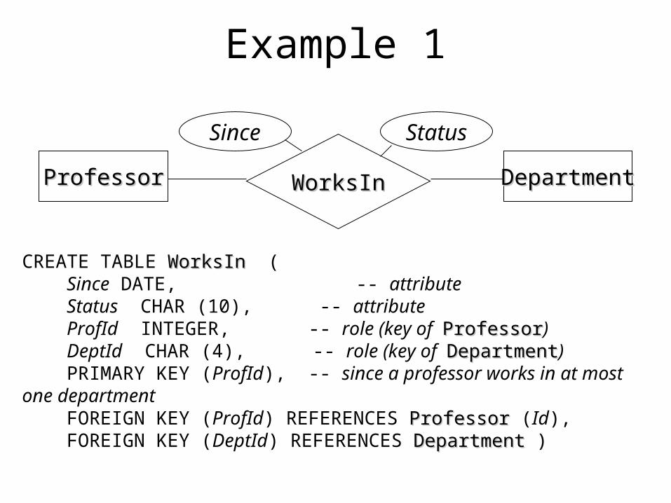
Example 1
WorksInWorksInProfessorProfessor DepartmentDepartment
Since Status
CREATE TABLE WorksInWorksIn ( Since DATE, -- attribute Status CHAR (10), -- attribute ProfId INTEGER, -- role (key of ProfessorProfessor) DeptId CHAR (4), -- role (key of DepartmentDepartment) PRIMARY KEY (ProfId), -- since a professor works in at most one department FOREIGN KEY (ProfId) REFERENCES ProfessorProfessor (Id), FOREIGN KEY (DeptId) REFERENCES DepartmentDepartment )
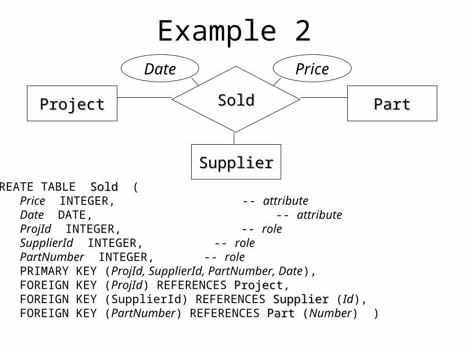
Example 2
SoldSoldProjectProject PartPart
Date Price
CREATE TABLE SoldSold ( Price INTEGER, -- attribute Date DATE, -- attribute ProjId INTEGER, -- role SupplierId INTEGER, -- role PartNumber INTEGER, -- role PRIMARY KEY (ProjId, SupplierId, PartNumber, Date), FOREIGN KEY (ProjId) REFERENCES ProjectProject, FOREIGN KEY (SupplierId) REFERENCES SupplierSupplier (Id), FOREIGN KEY (PartNumber) REFERENCES PartPart (Number) )
SupplierSupplier
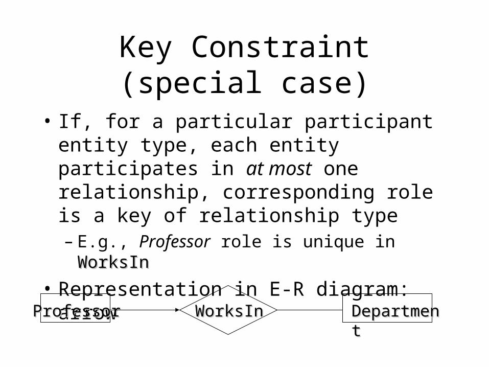
Key Constraint (special case)
• If, for a particular participant entity type, each entity participates in at most one relationship, corresponding role is a key of relationship type– E.g., Professor role is unique in WorksInWorksIn
• Representation in E-R diagram: arrow
WorksInWorksInProfessorProfessor DepartmentDepartment
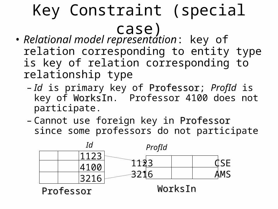
Key Constraint (special case)• Relational model representation: key of
relation corresponding to entity type is key of relation corresponding to relationship type– Id is primary key of ProfessorProfessor; ProfId is key of
WorksInWorksIn. Professor 4100 does not participate.– Cannot use foreign key in ProfessorProfessor since some
professors do not participate
112341003216
1123 CSE3216 AMS
ProfessorProfessor WorksInWorksIn
Id ProfId
Entity Type Hierarchies
• One entity type might be subtype of another– FreshmanFreshman is a subtype of StudentStudent
• A relationship exists between a FreshmanFreshman entity and the corresponding StudentStudent entity– e.g., Freshman John is related to Student John
• This relationship is called IsAIsA– FreshmanFreshman IsA StudentStudent
– The two entities related by IsA are always descriptions of the same real-world object
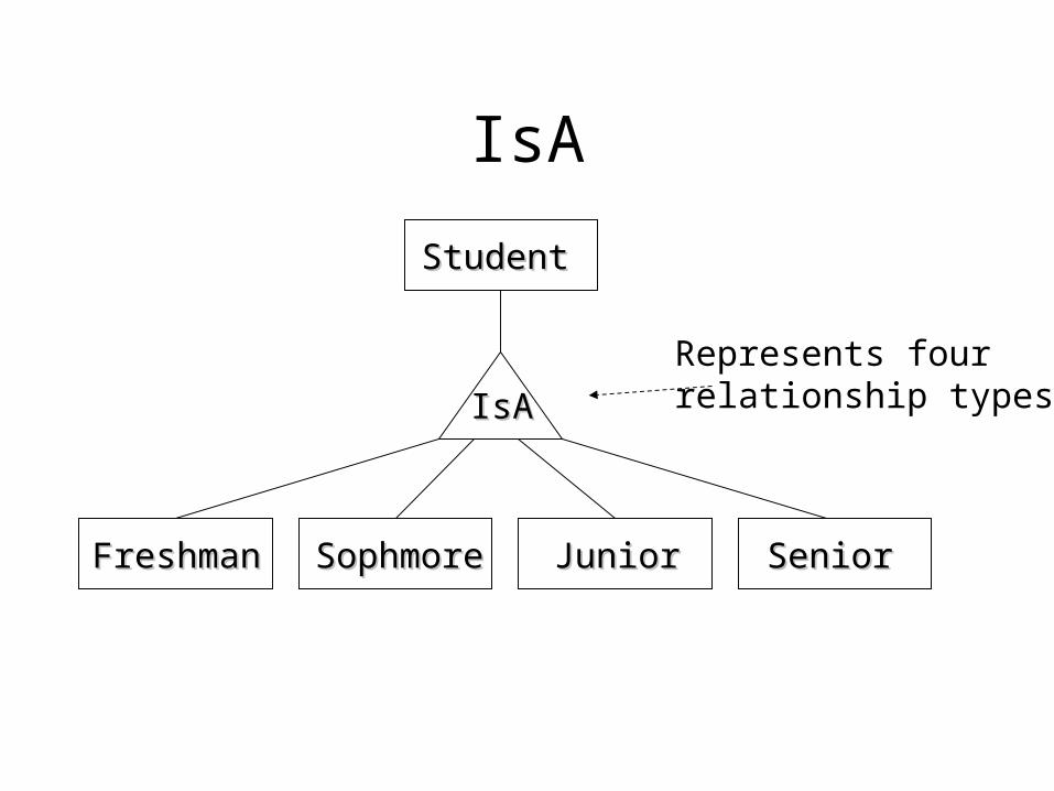
IsA
FreshmanFreshman SophmoreSophmore JuniorJunior SeniorSenior
StudentStudent
IsAIsA
Represents fourrelationship types
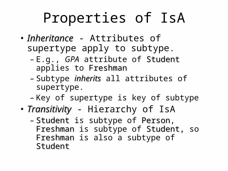
Properties of IsA• InheritanceInheritance - Attributes of supertype apply
to subtype.– E.g., GPA attribute of StudentStudent applies to
FreshmanFreshman– Subtype inheritsinherits all attributes of supertype.– Key of supertype is key of subtype
• TransitivityTransitivity - Hierarchy of IsA– StudentStudent is subtype of PersonPerson, FreshmanFreshman is
subtype of Student, Student, so Freshman Freshman is also a subtype of StudentStudent
IsA
• Advantage: Used to create a more concise and readable E-R diagram– Attributes common to different entity sets need
not be repeated– They can be grouped in one place as attributes
of supertype– Attributes of (sibling) subtypes can be different
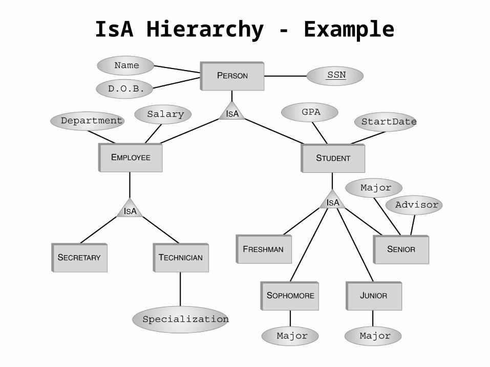
IsA Hierarchy - Example
Type Hierarchy
• Might have associated constraints:– Covering constraintCovering constraint: Union of subtype entities is
equal to set of supertype entities• Employee is either a secretary or a technician (or both)
– Disjointness constraintDisjointness constraint: Sets of subtype entities are disjoint from one another
• FreshmanFreshman, SophomoreSophomore, JuniorJunior, SeniorSenior are disjoint sets
• Might be related to fragmentation of data
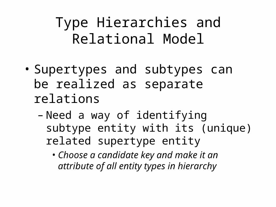
Type Hierarchies and Relational Model
• Supertypes and subtypes can be realized as separate relations– Need a way of identifying subtype entity with
its (unique) related supertype entity• Choose a candidate key and make it an attribute of
all entity types in hierarchy
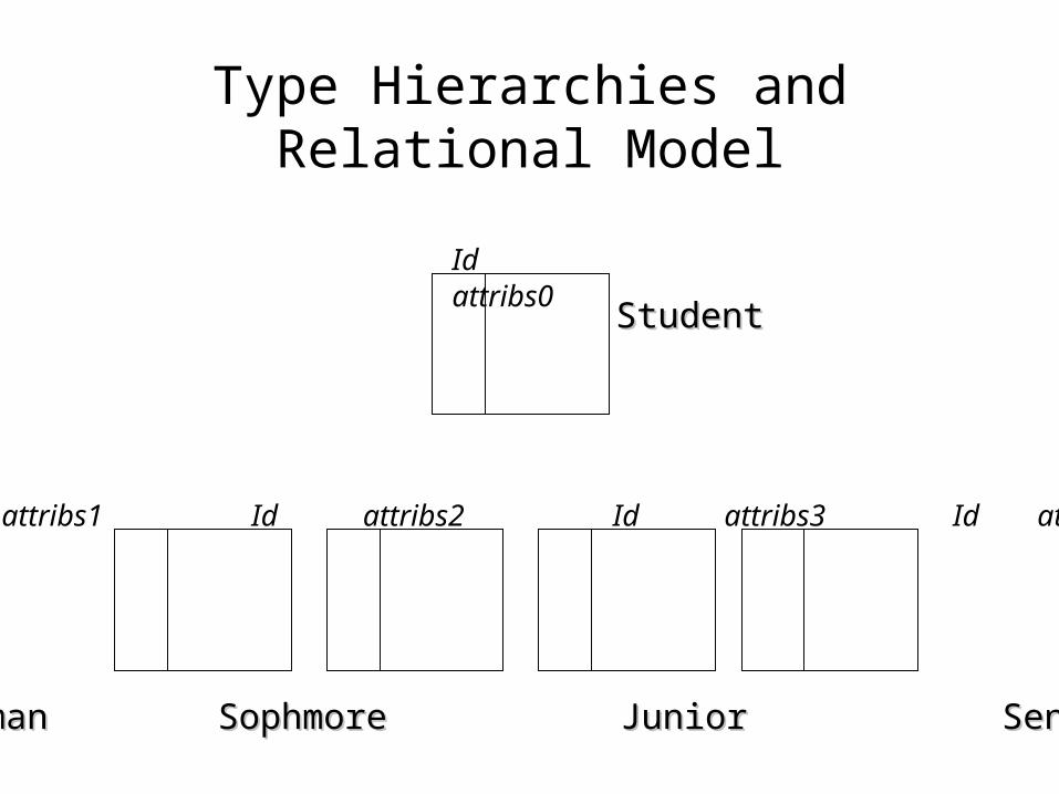
Type Hierarchies and Relational Model
Id attribs1 Id attribs2 Id attribs3 Id attribs4
Id attribs0
StudentStudent
FreshmanFreshman SophmoreSophmore JuniorJunior SeniorSenior
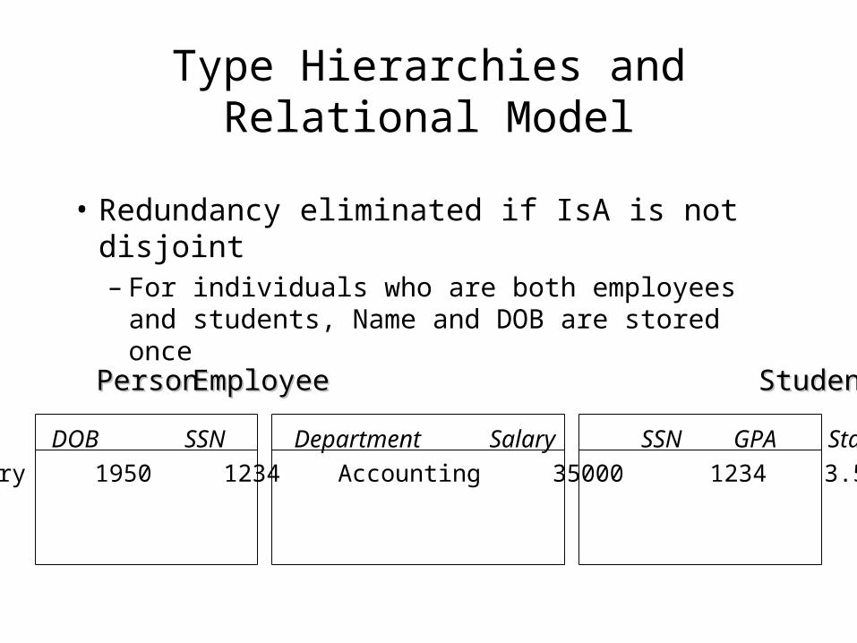
Type Hierarchies and Relational Model
• Redundancy eliminated if IsA is not disjoint– For individuals who are both employees and
students, Name and DOB are stored once
SSN Name DOB SSN Department Salary SSN GPA StartDate
1234 Mary 1950 1234 Accounting 35000 1234 3.5 1997
PersonPerson EmployeeEmployee StudentStudent
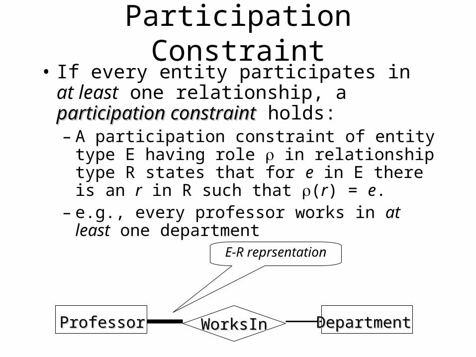
Participation Constraint• If every entity participates in at least one
relationship, a participation constraintparticipation constraint holds:– A participation constraint of entity type E
having role in relationship type R states that for e in E there is an r in R such that (r) = e.
– e.g., every professor works in at least one department
WorksInWorksInProfessorProfessor DepartmentDepartment
E-R reprsentation
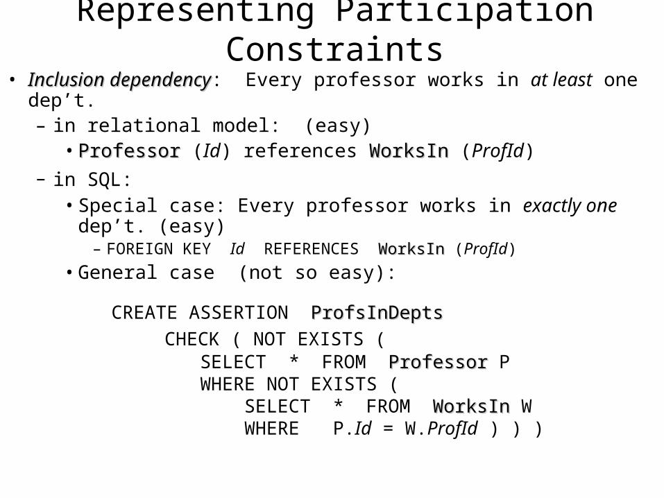
Representing Participation Constraints
• Inclusion dependencyInclusion dependency: Every professor works in at least one dep’t.– in relational model: (easy)
• ProfessorProfessor (Id) references WorksInWorksIn (ProfId)
– in SQL: • Special case: Every professor works in exactly one dep’t. (easy)
– FOREIGN KEY Id REFERENCES WorksInWorksIn (ProfId)
• General case (not so easy):
CREATE ASSERTION ProfsInDeptsProfsInDepts CHECK ( NOT EXISTS ( SELECT * FROM ProfessorProfessor P WHERE NOT EXISTS ( SELECT * FROM WorksInWorksIn W WHERE P.Id = W.ProfId ) ) )
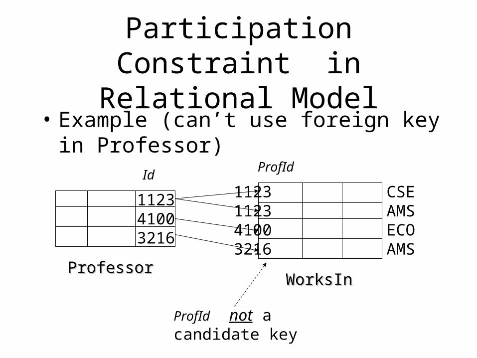
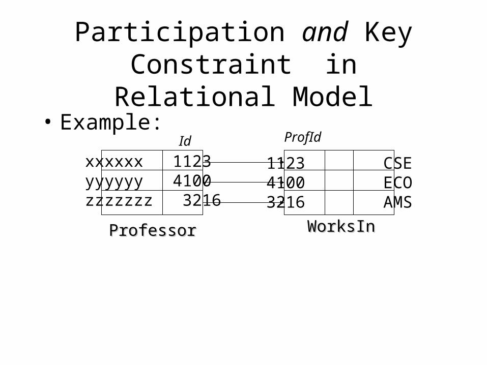
Participation Constraint in Relational Model
• Example (can’t use foreign key in Professor)
112341003216
1123 CSE1123 AMS4100 ECO3216 AMS
ProfessorProfessorWorksInWorksIn
IdProfId
ProfId not acandidate key
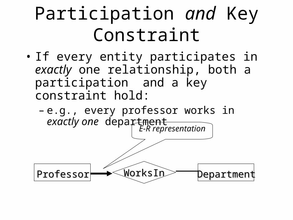
Participation and Key Constraint
• If every entity participates in exactly one relationship, both a participation and a key constraint hold:– e.g., every professor works in exactly one
department
WorksInWorksInProfessorProfessor DepartmentDepartment
E-R representation
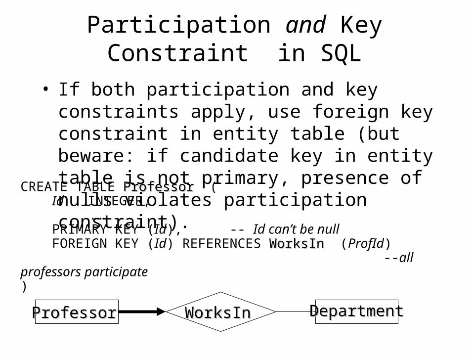
Participation and Key Constraint in SQL
• If both participation and key constraints apply, use foreign key constraint in entity table (but beware: if candidate key in entity table is not primary, presence of nulls violates participation constraint).
CREATE TABLE ProfessorProfessor ( Id INTEGER, …… PRIMARY KEY (Id), -- Id can’t be null FOREIGN KEY (Id) REFERENCES WorksInWorksIn (ProfId) --all professors participate )
ProfessorProfessor WorksInWorksIn DepartmentDepartment
Participation and Key Constraint in Relational Model
• Example:
xxxxxx 1123yyyyyy 4100zzzzzzz 3216
1123 CSE4100 ECO3216 AMS
ProfessorProfessor
Id ProfId
WorksInWorksIn
Participation and Key Constraint in Relational Model (again)
• Alternate solution if both key and participation constraints apply: merge the tables representing the entity and relationship sets– Since there is a 1-1 and onto relationship
between the rows of the entity set and the relationship sets, might as well put all the attributes in one table
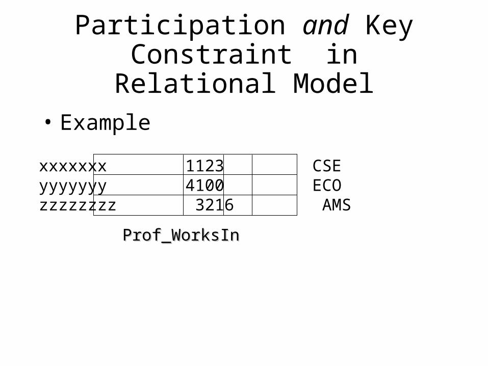
Participation and Key Constraint in Relational Model
• Example
xxxxxxx 1123 CSEyyyyyyy 4100 ECOzzzzzzzz 3216 AMS
Prof_WorksInProf_WorksIn
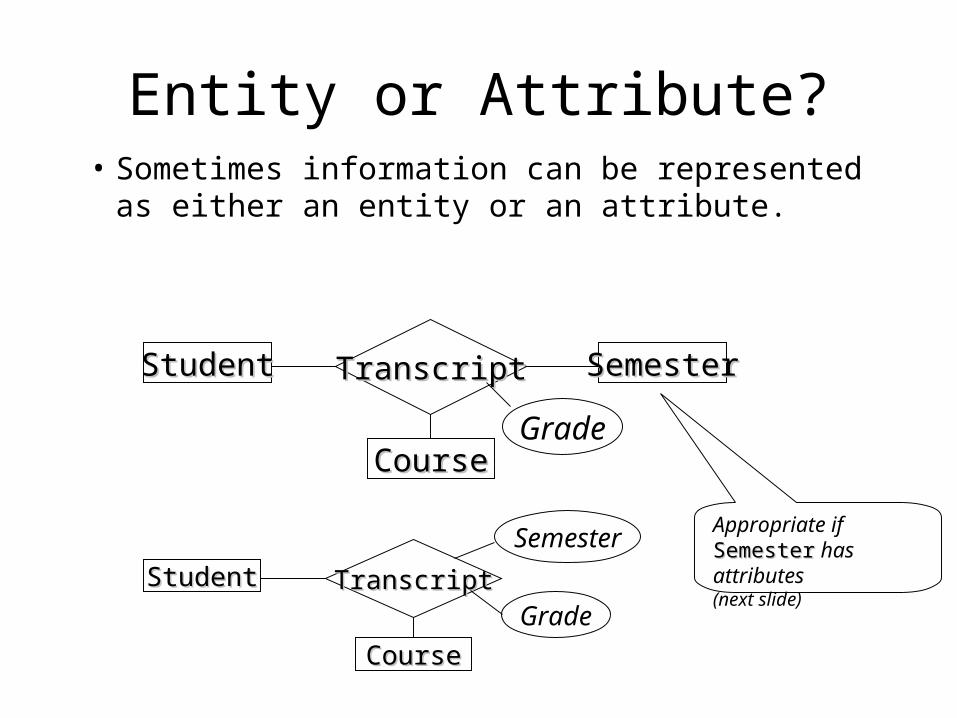
Entity or Attribute?• Sometimes information can be represented
as either an entity or an attribute.
StudentStudent SemesterSemester
CourseCourse
TranscriptTranscript
Grade
StudentStudent
CourseCourse
TranscriptTranscriptGrade
SemesterAppropriate if SemesterSemester has attributes(next slide)
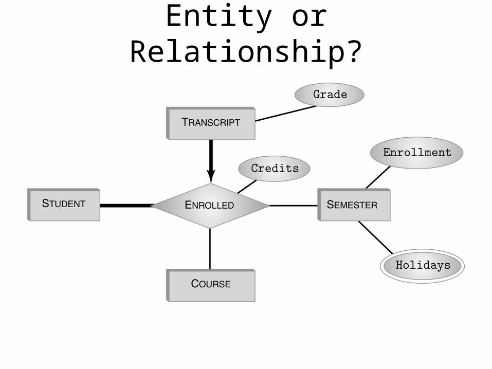
Entity or Relationship?
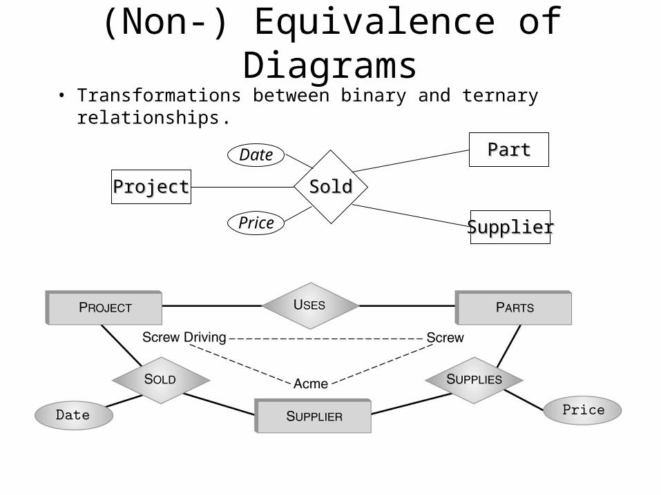
(Non-) Equivalence of Diagrams• Transformations between binary and ternary relationships.
SoldSoldProjectProject
PartPart
SupplierSupplier
Date
Price
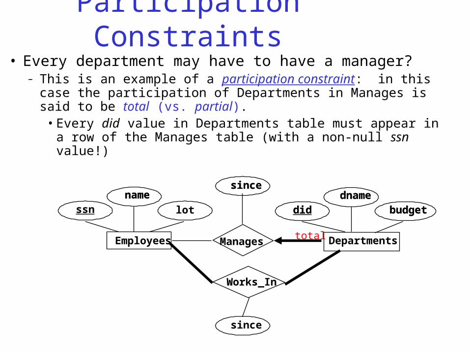
Participation Constraints• Every department may have to have a manager?
– This is an example of a participation constraint: in this case the participation of Departments in Manages is said to be total (vs. partial).
• Every did value in Departments table must appear in a row of the Manages table (with a non-null ssn value!)
lot
name dnamebudgetdid
sincename dname
budgetdid
since
Manages
since
DepartmentsEmployees
ssn
Works_In
total
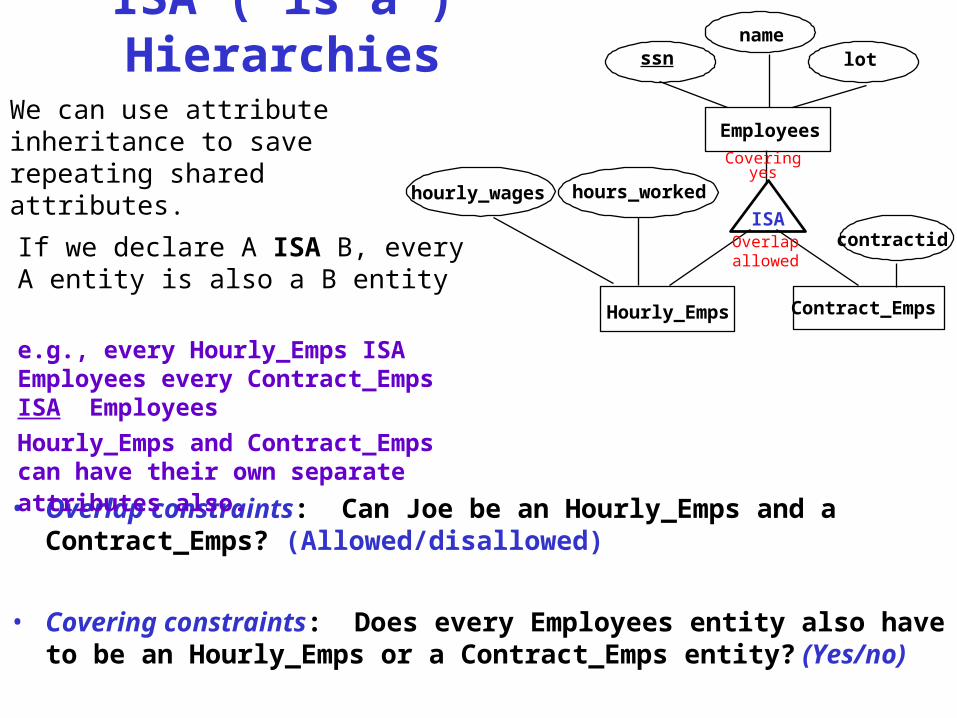
ISA (`is a’) Hierarchies
namessn lot
hourly_wages hours_worked
contractid
We can use attribute inheritance to save repeating shared attributes.
• Overlap constraints: Can Joe be an Hourly_Emps and a Contract_Emps? (Allowed/disallowed)
• Covering constraints: Does every Employees entity also have to be an Hourly_Emps or a Contract_Emps entity? (Yes/no)
Contract_Emps
Employees
ISA
Hourly_Emps
If we declare A ISA B, every A entity is also a B entity
e.g., every Hourly_Emps ISA Employees every Contract_Emps ISA Employees
Hourly_Emps and Contract_Emps can have their own separate attributes also.
Coveringyes
Overlapallowed
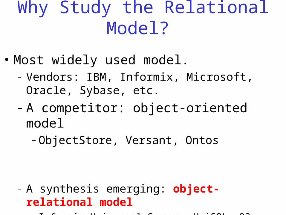
Why Study the Relational Model?
• Most widely used model.– Vendors: IBM, Informix, Microsoft, Oracle, Sybase, etc.
– A competitor: object-oriented model – ObjectStore, Versant, Ontos
– A synthesis emerging: object-relational model• Informix Universal Server, UniSQL, O2, Oracle, DB2
• Really just a more flexible relational model
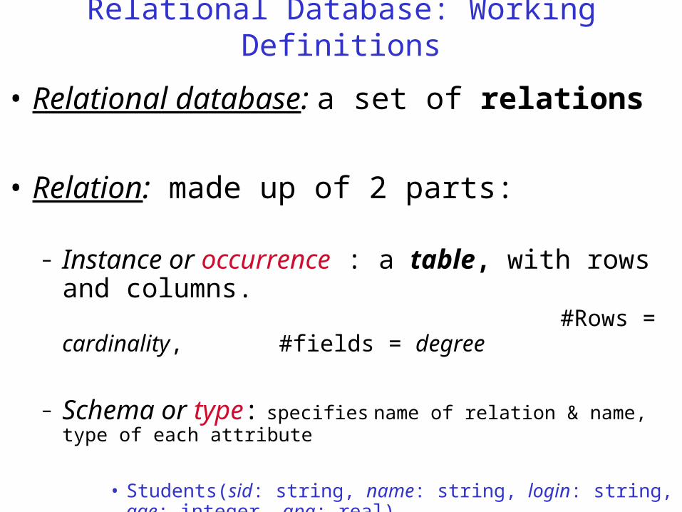
Relational Database: Working Definitions
• Relational database: a set of relations
• Relation: made up of 2 parts:
– Instance or occurrence : a table, with rows and columns. #Rows = cardinality, #fields =
degree
– Schema or type: specifies name of relation & name, type of each attribute
• Students(sid: string, name: string, login: string, age: integer, gpa: real).
• Strictly, a relation is a set of tuples but it is common to think of it as a table (sequence of rows made up of a sequence of attribute values)
Logical Database Design and the Relational Model (part 1)
CS263 Lecture 5
The relational model
• Was introduced in 1970 by Dr. E. F. Codd (of IBM)
• Commercial relational databases began to appear in the 1980s
• Today relational databases have become the dominant technology for database management
The relational model
• Data is represented in the form of tables, and the model has 3 components
• Data structure – data are organised in the form of tables with rows and columns
• Data manipulation – powerful operations (using the SQL language) are used to manipulate data stored in the relations
• Data integrity – facilities are included to specify business rules that maintain the integrity of data when they are manipulated
Relational definitions
• A relation is a named, two-dimensional table of data
• Every relation has a unique name, and consists of a set of named columns and an arbitrary number of unnamed rows
• An attribute is a named column of a relation, and every attribute value is atomic.
• Every row is unique, and corresponds to a record that contains data attributes for a single entity.
• The order of the columns is irrelevant.
• The order of the rows is irrelevant.
Relational structure
• We can express the structure of a relation by a Tuple, a shorthand notation
• The name of the relation is followed (in parentheses) by the names of the attributes of that relation, e.g.:
• EMPLOYEE1(Emp_ID,Name,Dept,Salary)
Relational keys
• Must be able to store and retrieve a row of data in a relation, based on the data values stored in that row
• A primary key is an attribute (or combination of attributes) that uniquely identifies each row in a relation.
• The primary key in the EMPLOYEE1 relation is EMP_ID (this is why it is underlined) as in:
• EMPLOYEE1(Emp_ID,Name,Dept,Salary)
Composite and foreign keys
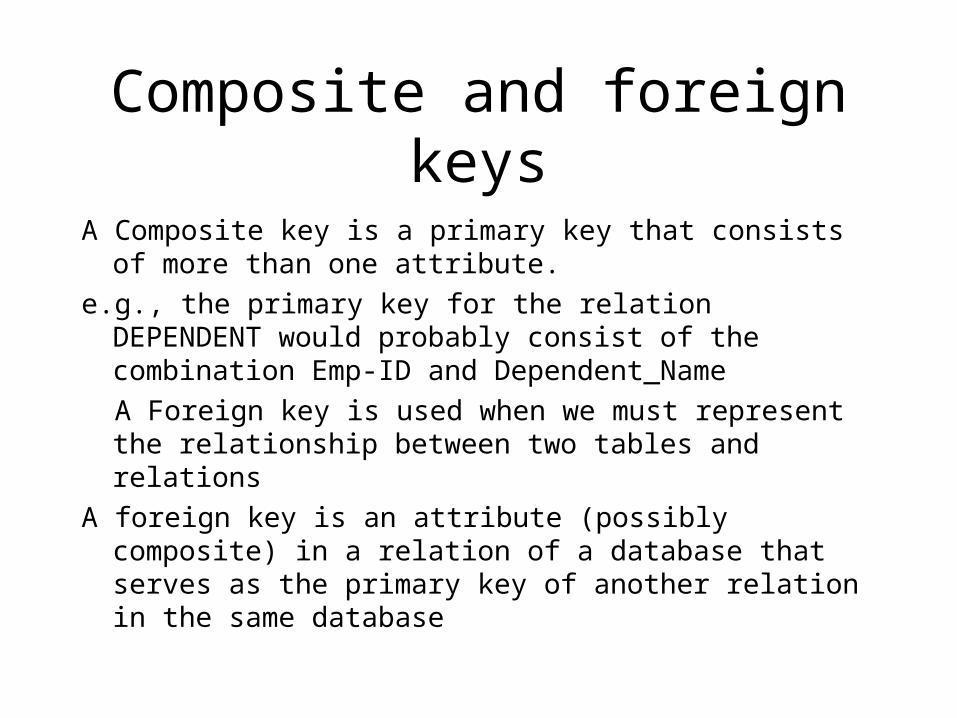
A Composite key is a primary key that consists of more than one attribute.
e.g., the primary key for the relation DEPENDENT would probably consist of the combination Emp-ID and Dependent_Name
A Foreign key is used when we must represent the relationship between two tables and relations
A foreign key is an attribute (possibly composite) in a relation of a database that serves as the primary key of another relation in the same database
Foreign keys
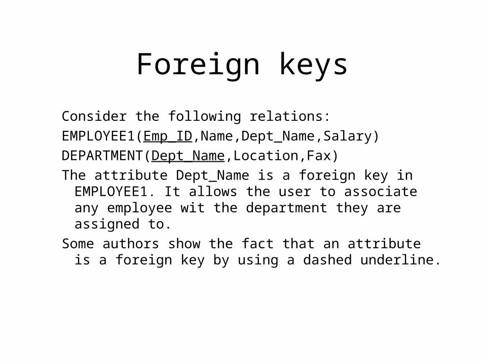
Consider the following relations:
EMPLOYEE1(Emp_ID,Name,Dept_Name,Salary)
DEPARTMENT(Dept_Name,Location,Fax)
The attribute Dept_Name is a foreign key in EMPLOYEE1. It allows the user to associate any employee wit the department they are assigned to.
Some authors show the fact that an attribute is a foreign key by using a dashed underline.
Removing multivalued attributes from tables
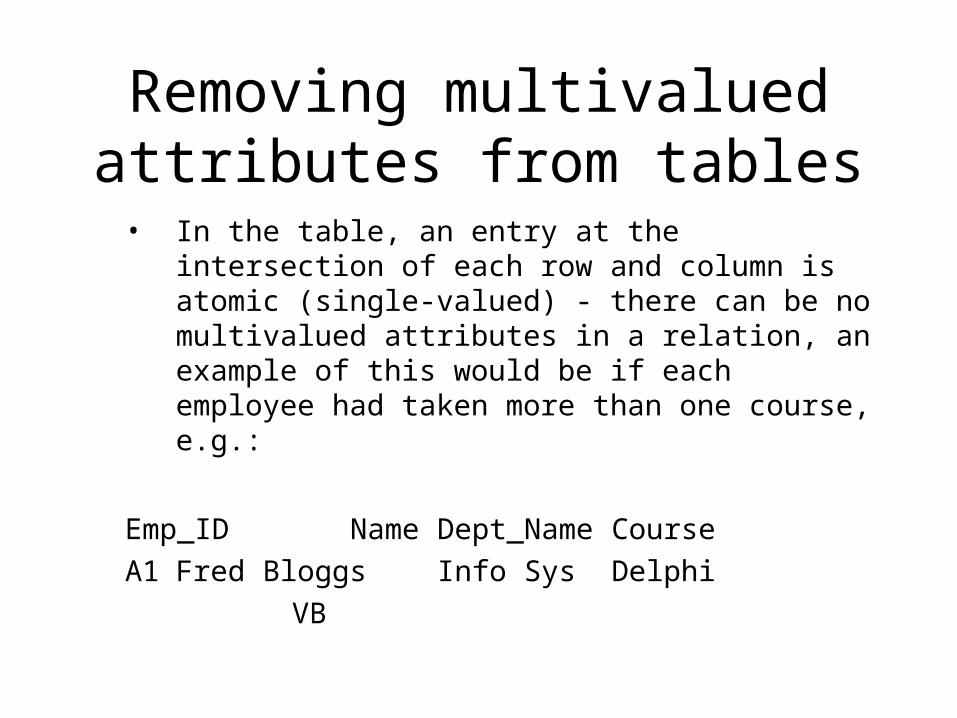
• In the table, an entry at the intersection of each row and column is atomic (single-valued) - there can be no multivalued attributes in a relation, an example of this would be if each employee had taken more than one course, e.g.:
Emp_ID Name Dept_Name Course
A1 Fred Bloggs Info Sys Delphi
VB
Removing multivalued attributes from tables
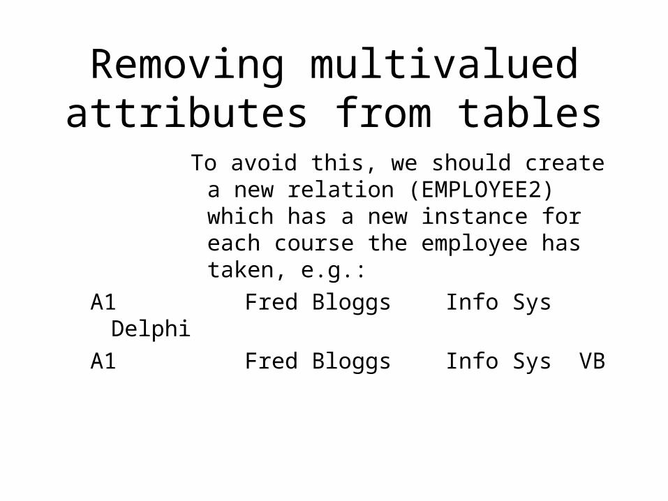
To avoid this, we should create a new relation (EMPLOYEE2) which has a new instance for each course the employee has taken, e.g.:
A1 Fred Bloggs Info Sys Delphi
A1 Fred Bloggs Info Sys VB
Example database
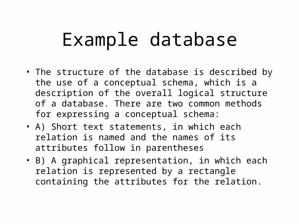
• The structure of the database is described by the use of a conceptual schema, which is a description of the overall logical structure of a database. There are two common methods for expressing a conceptual schema:
• A) Short text statements, in which each relation is named and the names of its attributes follow in parentheses
• B) A graphical representation, in which each relation is represented by a rectangle containing the attributes for the relation.
Expressing the conceptual schema
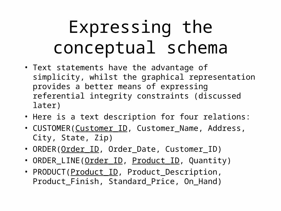
• Text statements have the advantage of simplicity, whilst the graphical representation provides a better means of expressing referential integrity constraints (discussed later)
• Here is a text description for four relations:
• CUSTOMER(Customer_ID, Customer_Name, Address, City, State, Zip)
• ORDER(Order_ID, Order_Date, Customer_ID)
• ORDER_LINE(Order_ID, Product_ID, Quantity)
• PRODUCT(Product_ID, Product_Description, Product_Finish, Standard_Price, On_Hand)
Expressing the conceptual schema
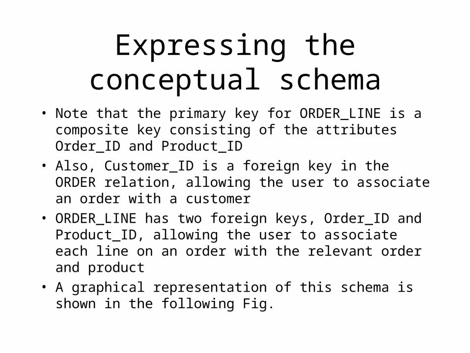
• Note that the primary key for ORDER_LINE is a composite key consisting of the attributes Order_ID and Product_ID
• Also, Customer_ID is a foreign key in the ORDER relation, allowing the user to associate an order with a customer
• ORDER_LINE has two foreign keys, Order_ID and Product_ID, allowing the user to associate each line on an order with the relevant order and product
• A graphical representation of this schema is shown in the following Fig.
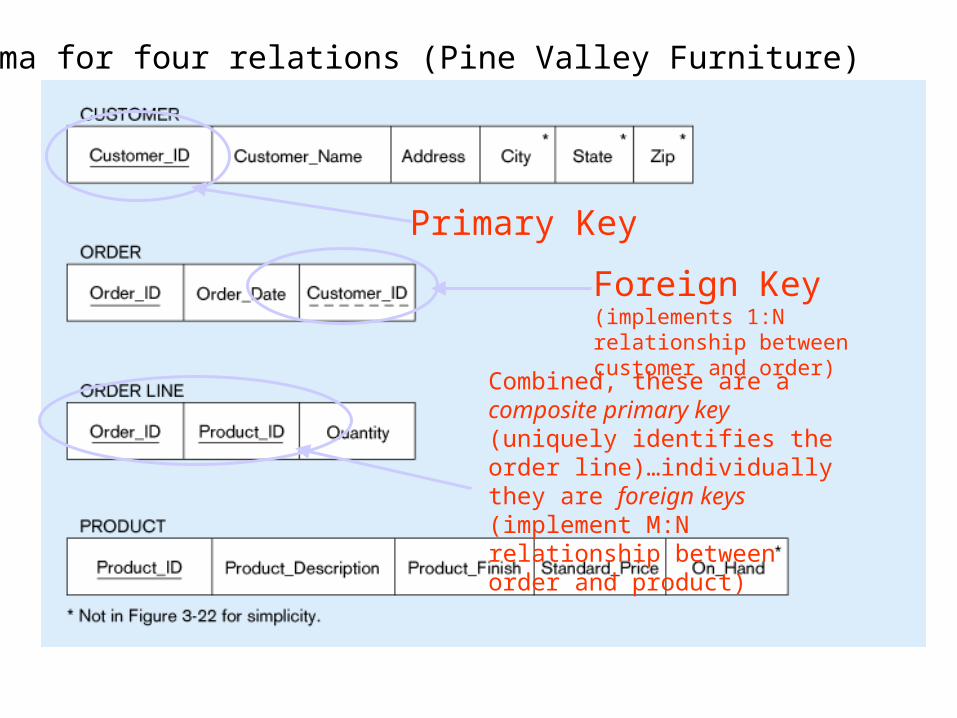
Schema for four relations (Pine Valley Furniture)
Primary Key
Foreign Key (implements 1:N relationship between customer and order)
Combined, these are a composite primary key (uniquely identifies the order line)…individually they are foreign keys (implement M:N relationship between order and product)
Integrity constraints
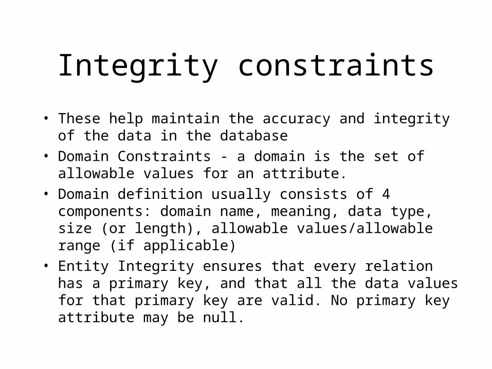
• These help maintain the accuracy and integrity of the data in the database
• Domain Constraints - a domain is the set of allowable values for an attribute.
• Domain definition usually consists of 4 components: domain name, meaning, data type, size (or length), allowable values/allowable range (if applicable)
• Entity Integrity ensures that every relation has a primary key, and that all the data values for that primary key are valid. No primary key attribute may be null.
Entity integrity
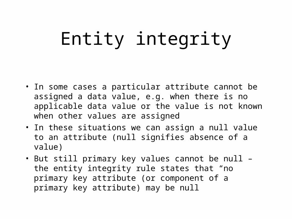
• In some cases a particular attribute cannot be assigned a data value, e.g. when there is no applicable data value or the value is not known when other values are assigned
• In these situations we can assign a null value to an attribute (null signifies absence of a value)
• But still primary key values cannot be null – the entity integrity rule states that “no primary key attribute (or component of a primary key attribute) may be null
Integrity constraints
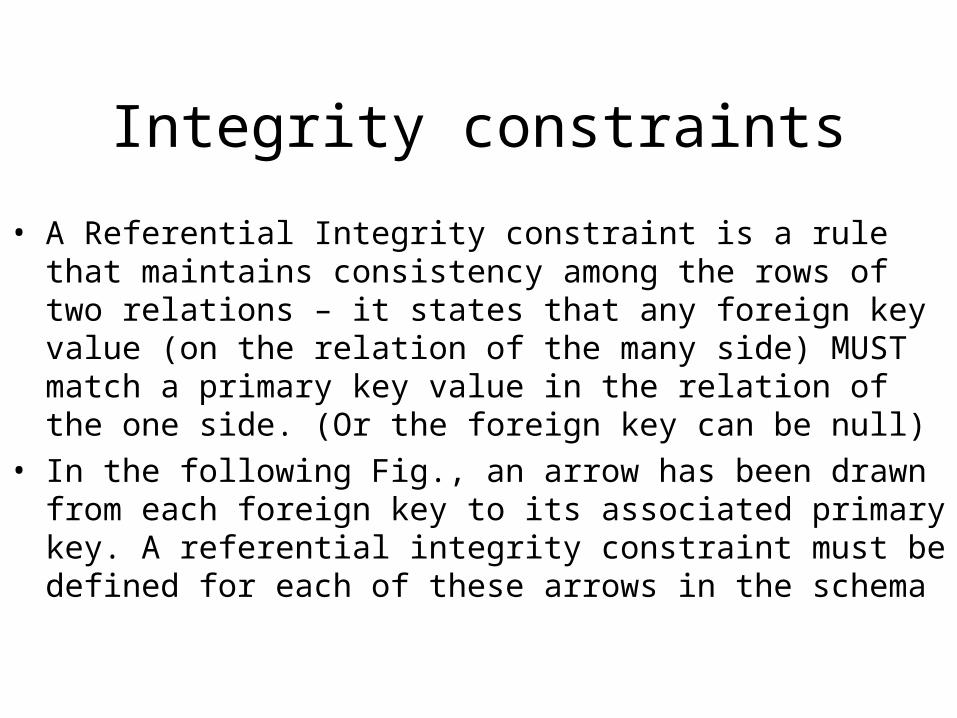
• A Referential Integrity constraint is a rule that maintains consistency among the rows of two relations – it states that any foreign key value (on the relation of the many side) MUST match a primary key value in the relation of the one side. (Or the foreign key can be null)
• In the following Fig., an arrow has been drawn from each foreign key to its associated primary key. A referential integrity constraint must be defined for each of these arrows in the schema
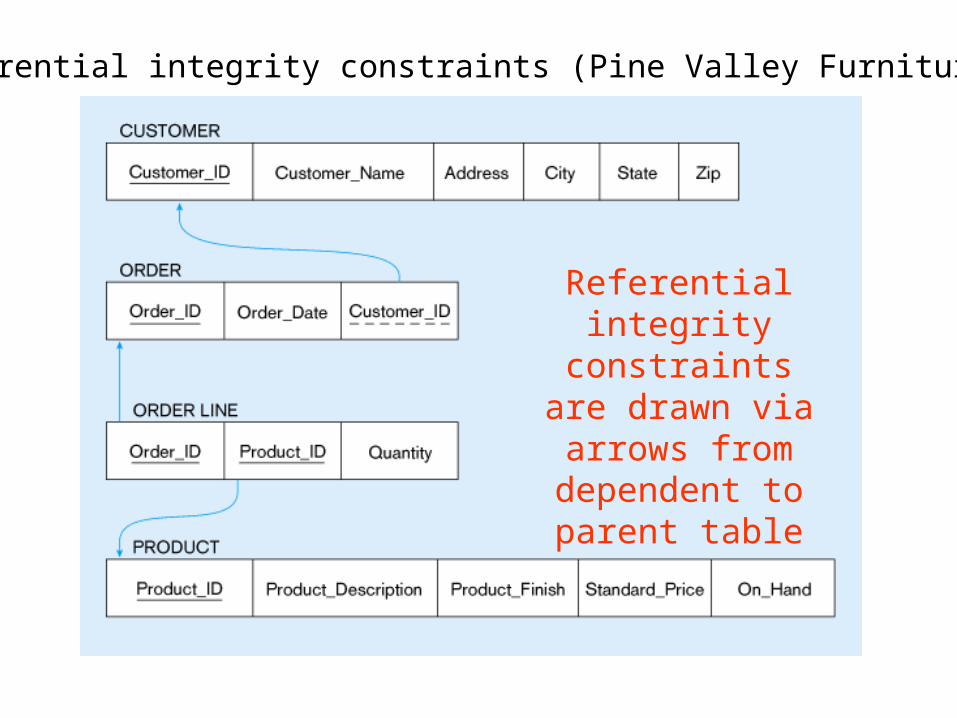
Referential integrity constraints (Pine Valley Furniture)
Referential integrity
constraints are drawn via arrows from dependent to
parent table
Referential integrity
• How do you know if a foreign key is allowed to be null?
• In this example, as each ORDER must have a CUSTOMER the foreign key of Customer_ID cannot be null on the ORDER relation
• Whether a foreign key can be null must be specified as a property of the foreign key attribute when the database is designed
Referential integrity
Whether foreign key can be null can be complex to model, e.g. what happens to order data if we choose to delete a customer who has submitted orders? We may want to see sales even though we do not care about the customer anymore. 3 choices are possible:
Restrict – don’t allow delete of “parent” side if related rows exist in “dependent” side, i.e. prohibit deletion of the customer until all associated orders are first deleted
Referential integrity
Cascade – automatically delete “dependent” side rows that correspond with the “parent” side row to be deleted, i.e. delete the associated orders, in which case we lose not only the customer but also the sales history
Set-to-Null – set the foreign key in the dependent side to null if deleting from the parent side - an exception that says although an order must have a customer_ID value when the order is created, Customer_ID can become null later if the associated customer is deleted [not allowed for weak entities]
Action assertions
Are business rules such as “A person may purchase a ticket for the celebrity football game only if that person is a season-ticket holder”
There are various techniques for defining and enforcing such rules, that will be discussed later
Creating relational tables
• These example tables are created using CREATE TABLE statements from SQL
• In practice, they are usually created in the implementation phase later on in the development process
• However, we create them here to explain some concepts
• One table is created for each table shown in the relational schema (previous Fig.)
Creating relational tables
• Each attribute is defined, taking the data type and length from the domain definitions
• For example, the attribute Customer_Name can be defined as a VARCHAR (variable character) type with length 25
• By specifying NOT NULL, each attribute can be constrained from being assigned a null value
• The primary key for each table is specified using the PRIMARY KEY clause at the end of each table definition
Creating relational tables
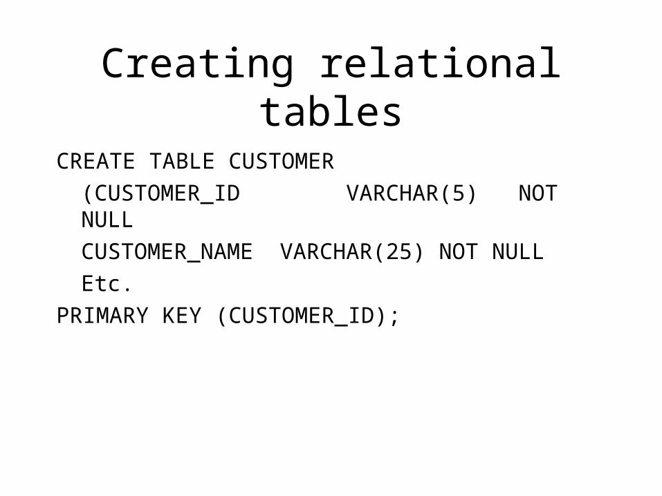
CREATE TABLE CUSTOMER
(CUSTOMER_ID VARCHAR(5) NOT NULL
CUSTOMER_NAME VARCHAR(25) NOT NULL
Etc.
PRIMARY KEY (CUSTOMER_ID);
Creating relational tables
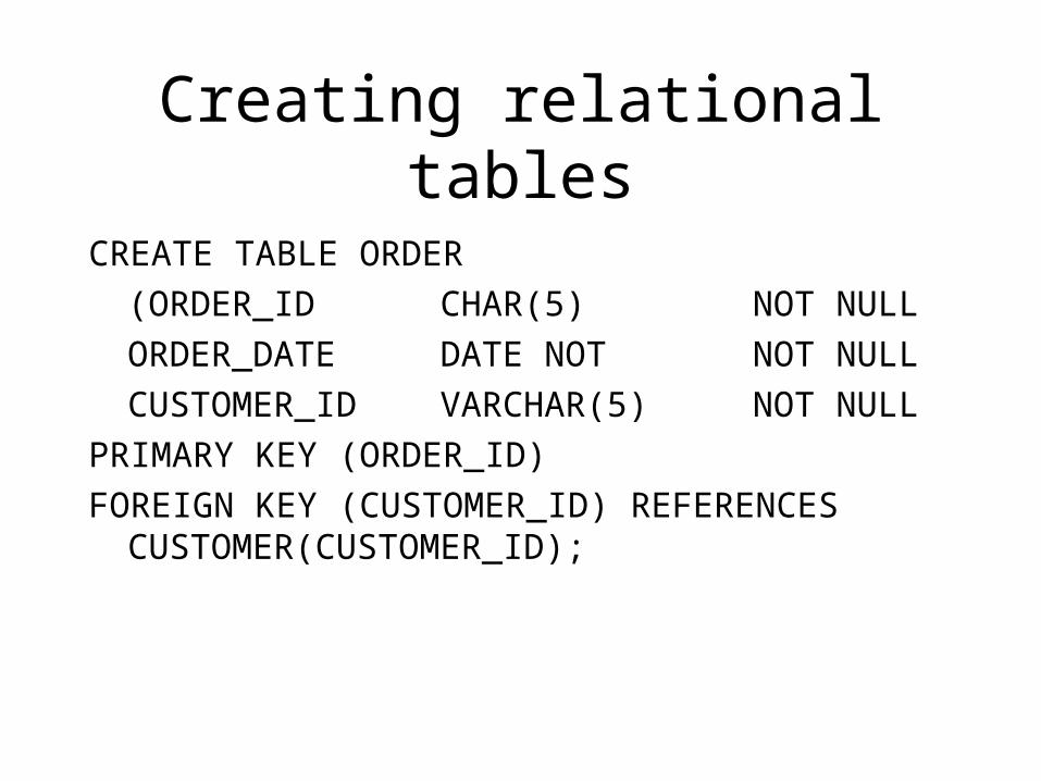
CREATE TABLE ORDER
(ORDER_ID CHAR(5) NOT NULL
ORDER_DATE DATE NOT NOT NULL
CUSTOMER_ID VARCHAR(5) NOT NULL
PRIMARY KEY (ORDER_ID)
FOREIGN KEY (CUSTOMER_ID) REFERENCES CUSTOMER(CUSTOMER_ID);
Creating relational tables
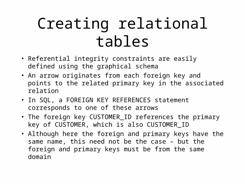
• Referential integrity constraints are easily defined using the graphical schema
• An arrow originates from each foreign key and points to the related primary key in the associated relation
• In SQL, a FOREIGN KEY REFERENCES statement corresponds to one of these arrows
• The foreign key CUSTOMER_ID references the primary key of CUSTOMER, which is also CUSTOMER_ID
• Although here the foreign and primary keys have the same name, this need not be the case – but the foreign and primary keys must be from the same domain
Creating relational tables
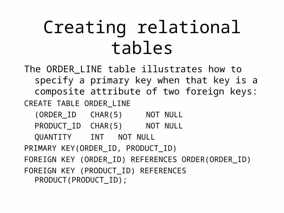
The ORDER_LINE table illustrates how to specify a primary key when that key is a composite attribute of two foreign keys:
CREATE TABLE ORDER_LINE
(ORDER_ID CHAR(5) NOT NULL
PRODUCT_ID CHAR(5) NOT NULL
QUANTITY INT NOT NULL
PRIMARY KEY(ORDER_ID, PRODUCT_ID)
FOREIGN KEY (ORDER_ID) REFERENCES ORDER(ORDER_ID)
FOREIGN KEY (PRODUCT_ID) REFERENCES PRODUCT(PRODUCT_ID);
Well-structured relations
• A well-structured relation contains minimal redundancy and allows users to insert, modify and delete the rows in a table without errors and inconsistencies
• Redundancies in a table (such as more than one entry for each EMPLOYEE) may result in errors and inconsistencies (anomalies) when the table is updated
• 3 Types of anomaly are possible, insertion, deletion and modification anomalies
Insertion anomaly
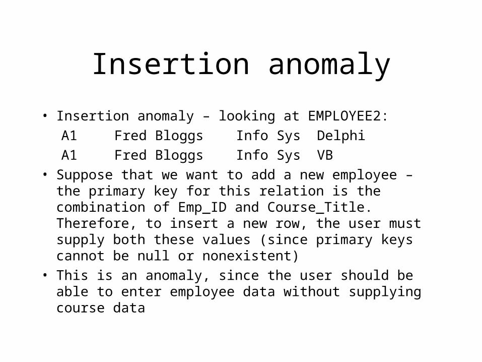
• Insertion anomaly – looking at EMPLOYEE2:
A1 Fred Bloggs Info Sys Delphi
A1 Fred Bloggs Info Sys VB
• Suppose that we want to add a new employee – the primary key for this relation is the combination of Emp_ID and Course_Title. Therefore, to insert a new row, the user must supply both these values (since primary keys cannot be null or nonexistent)
• This is an anomaly, since the user should be able to enter employee data without supplying course data
Deletion and modification anomalies
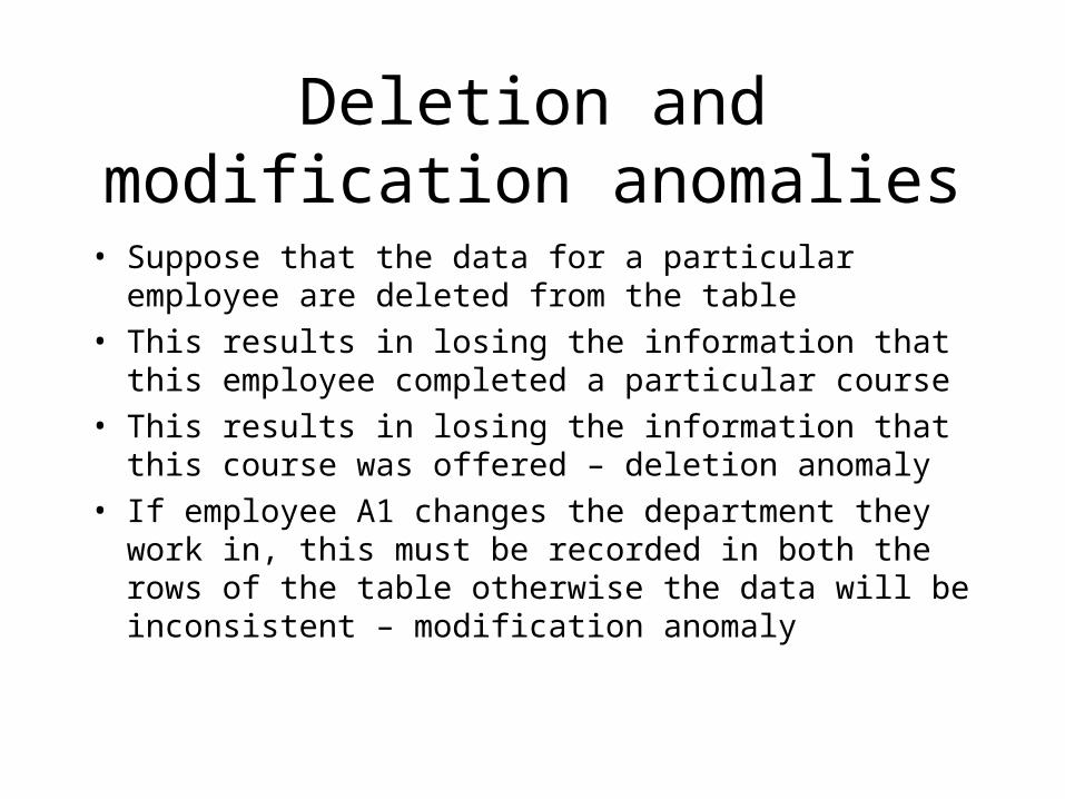
• Suppose that the data for a particular employee are deleted from the table
• This results in losing the information that this employee completed a particular course
• This results in losing the information that this course was offered – deletion anomaly
• If employee A1 changes the department they work in, this must be recorded in both the rows of the table otherwise the data will be inconsistent – modification anomaly
Anomalies
• These anomalies indicate that EMPLOYEE2 is not a well-structured relation
• We should use normalisation theory (discussed later) to divide EMPLOYEE2 into 2 relations, one called EMPLOYEE1 and one called EMP_COURSE that keeps track of the course details
Transforming ER diagrams into relations
• This can be done automatically by many CASE tools, but it is important to understand because:
• Case tools often cannot model complex data relationships such as ternary relationships and supertype/subtype relationships. For these situations you may have to perform these steps manually
• Sometimes alternative solutions exist, and you must choose the best
• You must be able to quality check the CASE tool results
Remember entity types!
• Regular entities – have an independent existence and generally represent real-world objects = [rectangles with a single line]
• Weak entities cannot exist on there own, they exist with an identifying relationship with an owner regular entity type = [[rectangles with a double line]]
• Associative entities (gerunds) are formed from many-to-many relationships between other entity types = [<rectangle enclosing the diamond relationship symbol>]
Step 1: map regular entities
• Each regular entity type in an ER diagram is transformed into a relation
• The name given to the relation is generally the same as the entity type
• Each simple attribute of the type becomes an attribute of the relation
• The identifier of the entity type becomes the primary key of the corresponding relation
• The following 2 Figs. show an example of this
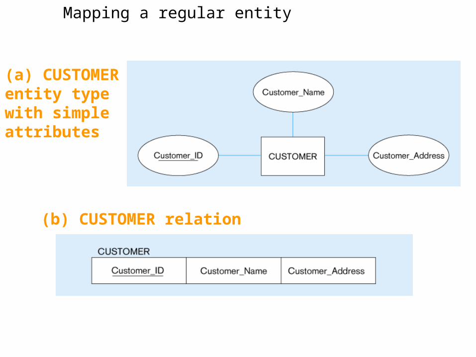
(a) CUSTOMER entity type with simple attributes
Mapping a regular entity
(b) CUSTOMER relation
Composite attributes
• When a regular entity type has composite attributes, only the simple component attributes of the composite attribute are included in the new relation
• The following Fig. Shows a variation on the previous one, where Customer_Address is represented as a composite attribute with components Street, City, State and Zip
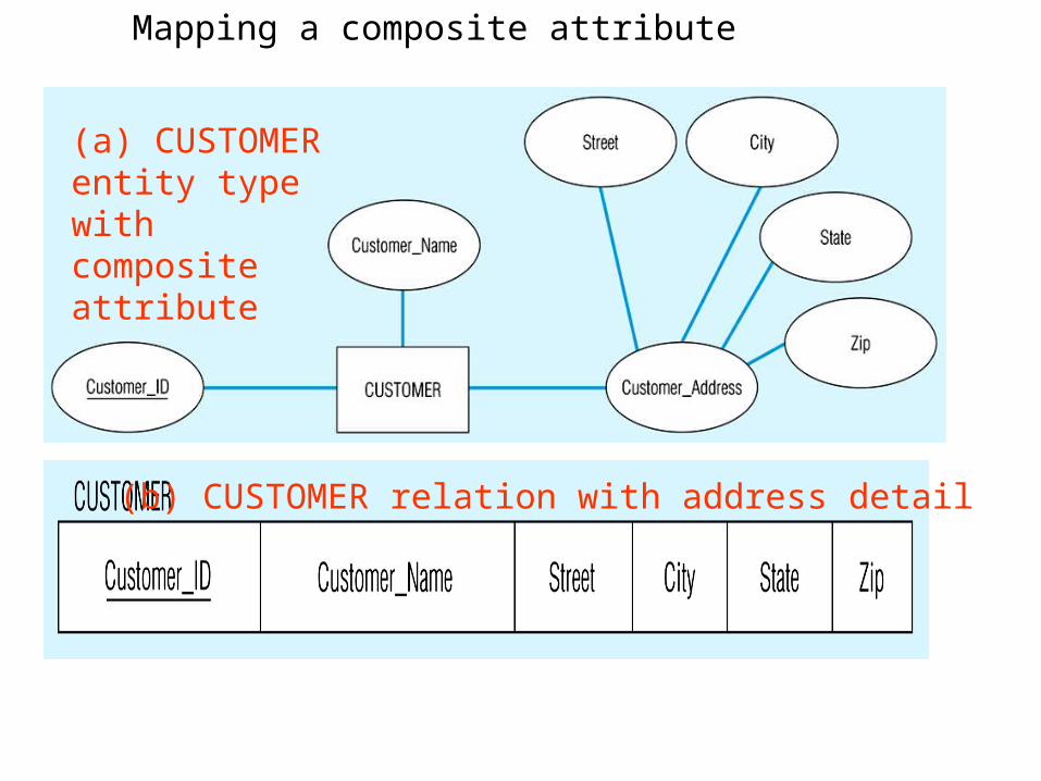
(a) CUSTOMER entity type with composite attribute
Mapping a composite attribute
(b) CUSTOMER relation with address detail
Multi-valued attributes
• Here two new relations (rather than one) are created
• First relation contains all of the attributes of the entity type except the multivalued attribute
• Second relation contains two attributes that form the primary key of the second relation
• The first of these is the primary key for the first relation, which becomes a foreign key in the second relation
• The second is the multivalued attribute
Multi-valued attributes
• In the following Fig. EMPLOYEE has ‘Skill’ as a multi-valued attribute
• The first relation EMPLOYEE has the primary key Employee_ID
• The second relation EMPLOYEE_SKILL has the two attributes Employee_ID and Skill, which form the primary key
• The relationship between foreign and primary keys is indicated by the arrow in the figure
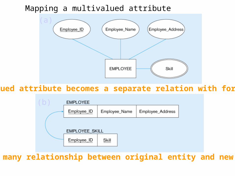
Mapping a multivalued attribute
1 – to – many relationship between original entity and new relation
(a)
Multivalued attribute becomes a separate relation with foreign key
(b)
Step 2: map weak entities
• You must already have created a relation corresponding to the identifying type
• For each weak entity type, create a new relation and include all of the simple attributes (or simple components of composite attributes) as attributes of this relation
• Then include the primary key of the identifying relation as a foreign key attribute in this new relation
• The primary key of the new relation is the combination of this primary key of the identifying and the partial identifier of the weak entity type
Map weak entities
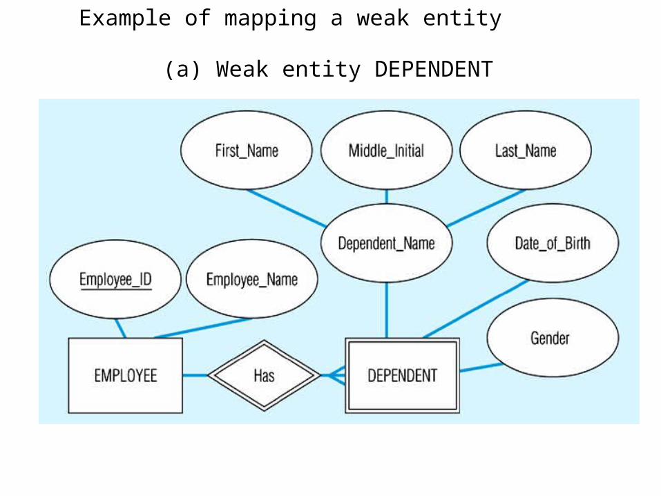
• The following figure shows the weak identity type DEPENDENT and its identifying entity type EMPLOYEE, linked by the identifying relationship ‘Has’
• The attribute Dependent_Name (the partial identifier for this relation) is a composite attribute with components First_Name, Middle_Initial and Last_Name – so we assume that for a given employee these items will uniquely identify a dependent. The primary key of DEPENDENT consists of four attributes: Employee_ID, First_Name, Middle_Initial and Last_Name. The foreign key relationship with its primary key is indicated by the arrow in the Fig.
Example of mapping a weak entity
(a) Weak entity DEPENDENT
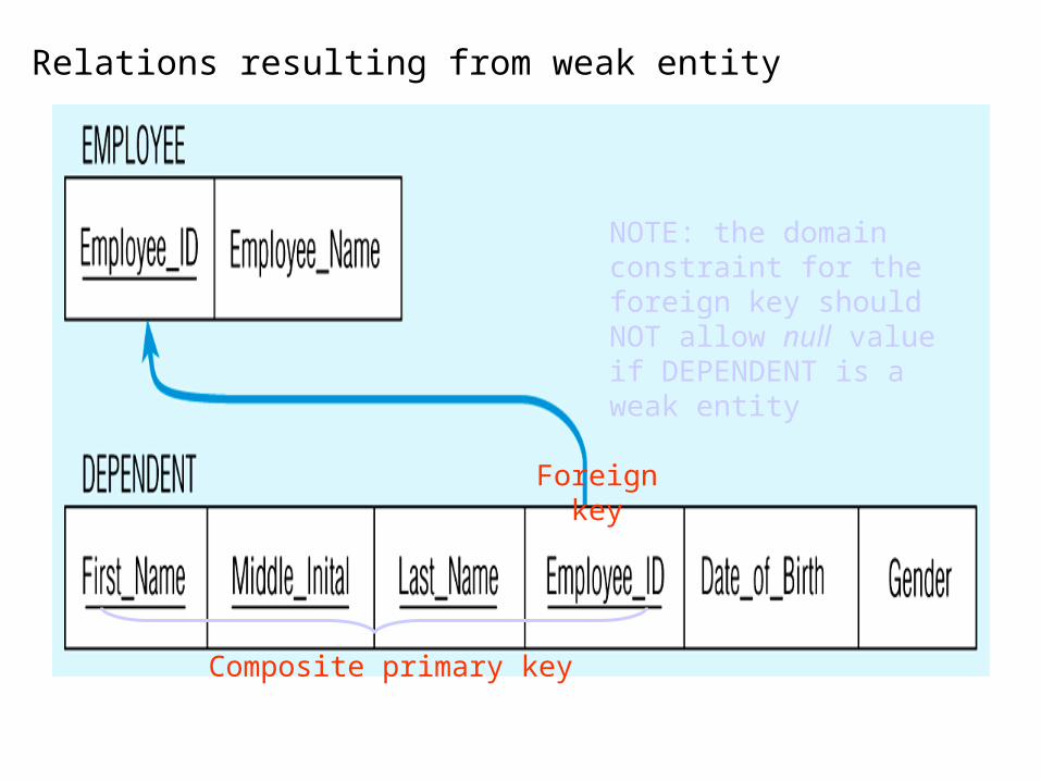
Relations resulting from weak entity
NOTE: the domain constraint for the foreign key should NOT allow null value if DEPENDENT is a weak entity
Foreign key
Composite primary key
Step 3: map binary relationships
• The procedure for representing relationships depends on both the degree of the relationships (unary, binary, ternary) and the cardinalities of the relationships
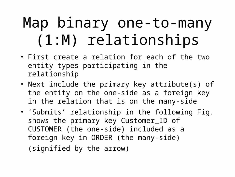
Map binary one-to-many (1:M) relationships
• First create a relation for each of the two entity types participating in the relationship
• Next include the primary key attribute(s) of the entity on the one-side as a foreign key in the relation that is on the many-side
• ‘Submits’ relationship in the following Fig. shows the primary key Customer_ID of CUSTOMER (the one-side) included as a foreign key in ORDER (the many-side)
(signified by the arrow)
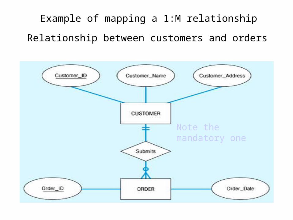
Example of mapping a 1:M relationship
Relationship between customers and orders
Note the mandatory one
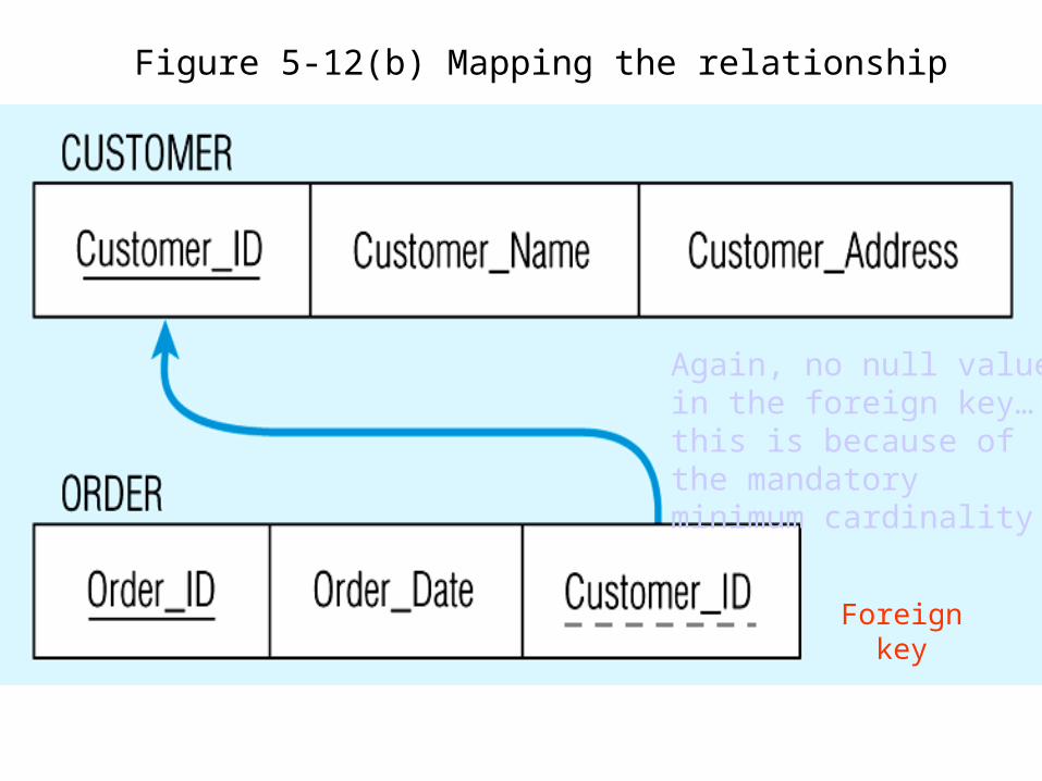
Figure 5-12(b) Mapping the relationship
Again, no null value in the foreign key…this is because of the mandatory minimum cardinality
Foreign key
Map binary many-to-many (M:N) relationships
• If such a relationship exists between entity types A and B, we create a new relation C, then include as foreign keys in C the primary keys for A and B, then these attributes become the primary key of C
• In the following Fig., first a relation is created for VENDOR and RAW_MATERIALS, then a relation QUOTE is created for the ‘Supplies’ relationship – with primary key formed from a combination of Vendor_ID and Material_ID (primary keys of VENDOR and RAW_MATERIALS). These are foreign keys that point to the respective primary keys
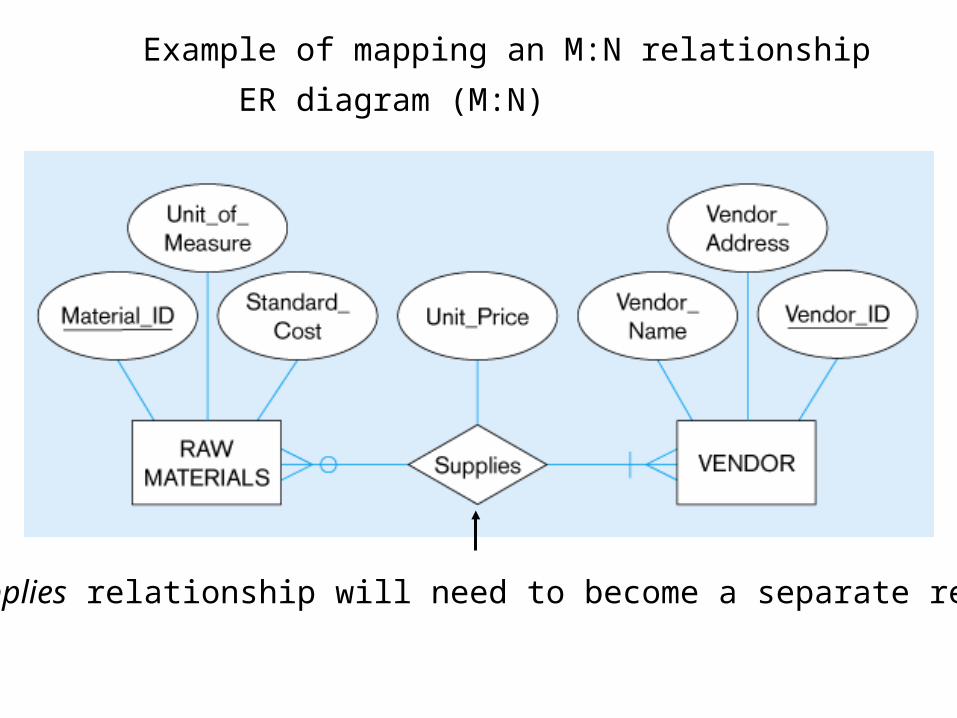
Example of mapping an M:N relationship
ER diagram (M:N)
The Supplies relationship will need to become a separate relation
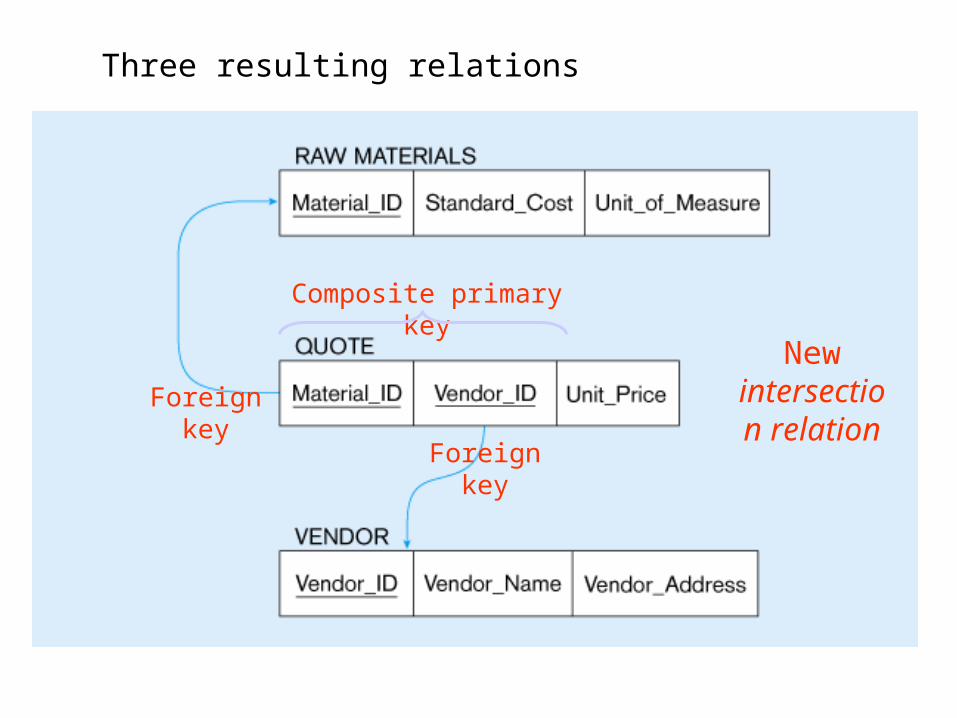
Three resulting relations
New intersection
relationForeign key
Foreign key
Composite primary key
Map binary one-to-one relationships
• These can be viewed as a special case of one-to-many relationships. Firstly, two relations are created, one for each of the participating entity types
• Secondly, the primary key of one of the relations is included as a foreign key in the other relation
• In a 1:1 relationship, the association in one direction is nearly always optional one, whilst the association in the other direction is mandatory one
• You should include in the relation on the optional side of the relationship the foreign key of the entity type that has the mandatory participation in the 1:1 relationship
Map binary one-to-one relationships
• This approach avoids the need to store null values in the foreign key attribute
• Any attributes associated wit the relationship itself are also included in the same relation as the foreign key
• The following Fig. Shows a binary 1:1 relationship between NURSE and CARE_CENTER, where each care centre must have a nurse who is in charge of that centre – so the association from care centre to nurse is a mandatory one, while the association from nurse to care centre is an optional one (since any nurse may or may not be in charge of a care centre)
Map binary one-to-one relationships
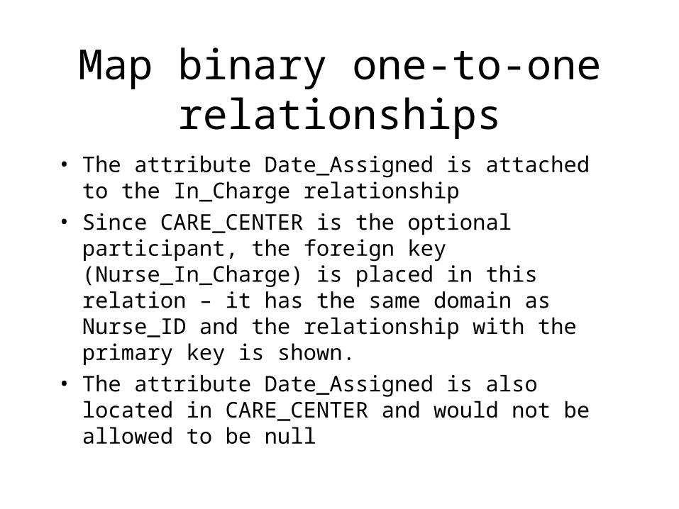
• The attribute Date_Assigned is attached to the In_Charge relationship
• Since CARE_CENTER is the optional participant, the foreign key (Nurse_In_Charge) is placed in this relation – it has the same domain as Nurse_ID and the relationship with the primary key is shown.
• The attribute Date_Assigned is also located in CARE_CENTER and would not be allowed to be null
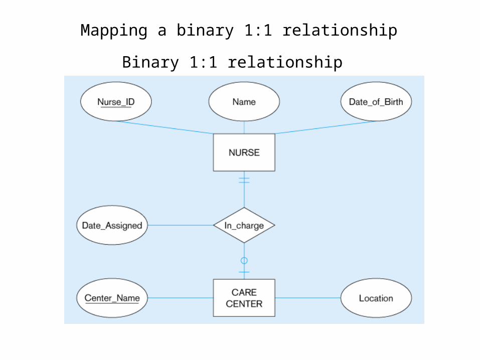
Mapping a binary 1:1 relationship
Binary 1:1 relationship
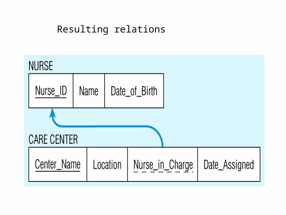
Resulting relations
Step 4: map associative entities
• When a user can best visualise a relationship as an associative entity (rather than an M:N relationship) we follow similar steps to mapping an M:N relationship
• Three relations are created, one for each of the two participating entity types and the third for the associative entity
• The relation formed is called the associative relation
• The next step depends on whether on the ER diagram an identifier was assigned to the associative entity
Identifier not assigned
• Here the default primary key for the associative relation consists of the two primary key attributes from the other two relations
• These attributes are then foreign keys that reference the other two relations
Identifier assigned
• Sometimes an identifier (called a surrogate identifier or key) is assigned to the associative entity type on the ER diagram. There are 2 possible reasons:
• A) The associative identity type has a natural identifier that is familiar to end users
• B) The default identifier (consisting of identifiers for each of the participating entity types) may not uniquely identify instances of the associative identity
• The process for mapping the associative entity is now modified
Identifier assigned
• As before a new associative relation is created to represent the associative entity
• However, the primary key for this relation is the identifier assigned on the ER diagram (rather than the default key)
• The primary keys for the two participating entity types are then included as foreign keys in the associative relation
• The following Fig. Shows the associative entity type SHIPMENT that links the CUSTOMER and VENDOR
entity types
Identifier assigned
• Shipment_No has been chosen as the identifier for two reasons:
• 1. Shipment_No is a natural identifier for this entity that is very familiar to end users
• 2. The default identifier consisting of the combination of Customer_ID and Vendor_ID does not uniquely identify the instances of shipment. In fact, a given vendor will make many shipments to a given customer
• The new associative relation is named SHIPMENT, with primary key Shipment_No. Customer_ID and Vendor_ID are included as foreign keys in this relation
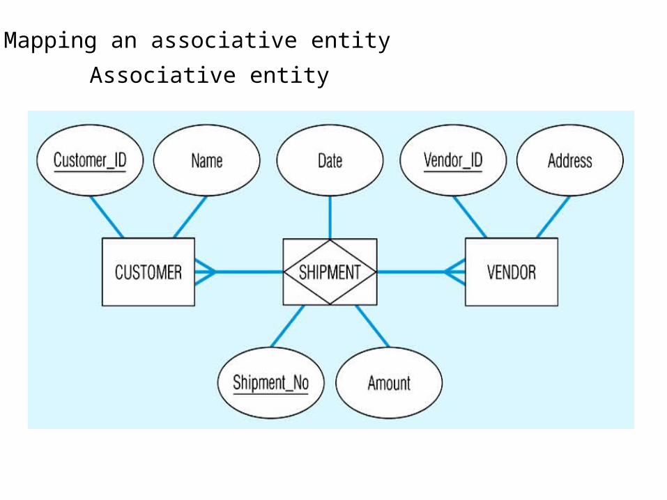
Mapping an associative entity
Associative entity
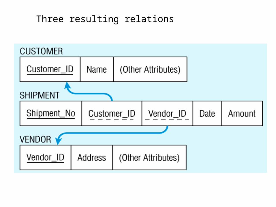
Three resulting relations
Relational Query Languages
• A major strength of the relational model: supports simple, powerful querying of data.
• Queries can be written intuitively (what, not how), and the DBMS is responsible for efficient evaluation
– Allows the optimizer to extensively re-order operations, and still ensure that the answer does not change.
The SQL Query Language
• Developed by IBM (system R) in the 1970s
• Jim Gray was the lead architect
• Need standards since it is used by many vendors
• Standards: – SQL-86– SQL-89 (minor revision)– SQL-92 (major revision)– SQL-99 (major extensions)
– Procedural constructs (if-then-else, loops, procs)– OO constructs (inheritance, polymorphism,…)
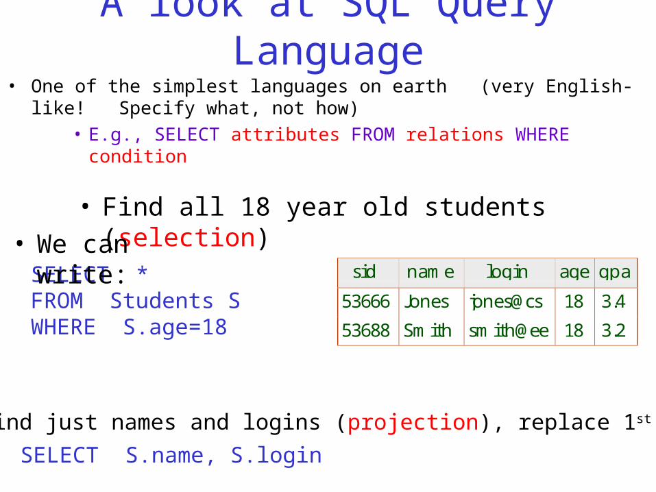
A look at SQL Query Language• One of the simplest languages on earth (very English-like!
Specify what, not how)• E.g., SELECT attributes FROM relations WHERE condition
•To find just names and logins (projection), replace 1st line:
SELECT S.name, S.login
sid name login age gpa
53666 Jones jones@cs 18 3.4
53688 Smith smith@ee 18 3.2
• Find all 18 year old students (selection)
SELECT *FROM Students SWHERE S.age=18
• We can write:
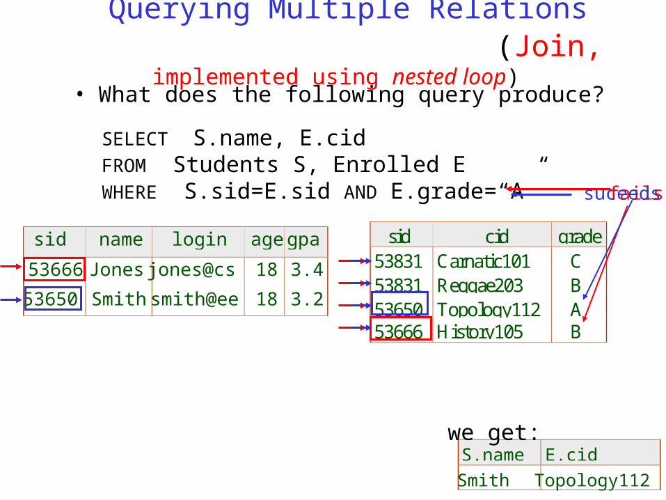
Querying Multiple Relations (Join, implemented using nested
loop)
S.name E.cid
Smith Topology112
we get:
• What does the following query produce?
SELECT S.name, E.cidFROM Students S, Enrolled EWHERE S.sid=E.sid AND E.grade=“A”
sid cid grade53831 Carnatic101 C53831 Reggae203 B53650 Topology112 A53666 History105 B
sid name login agegpa
53666 Jones jones@cs 18 3.4
53650 Smithsmith@ee 18 3.2
failssuceeds
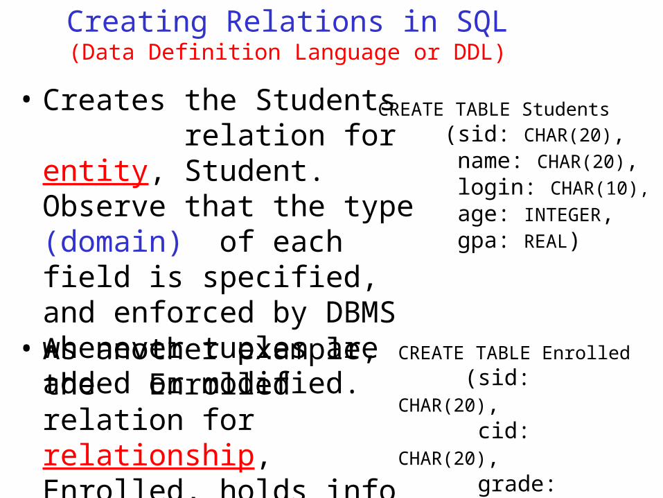
Creating Relations in SQL(Data Definition Language or DDL)
• Creates the Students relation for entity, Student. Observe that the type (domain) of each field is specified, and enforced by DBMS whenever tuples are added or modified.
CREATE TABLE Students(sid: CHAR(20), name: CHAR(20), login: CHAR(10), age: INTEGER, gpa: REAL)
CREATE TABLE Enrolled(sid: CHAR(20), cid: CHAR(20), grade:
CHAR(2))
• As another example, the Enrolled relation for relationship, Enrolled, holds info about courses students take.
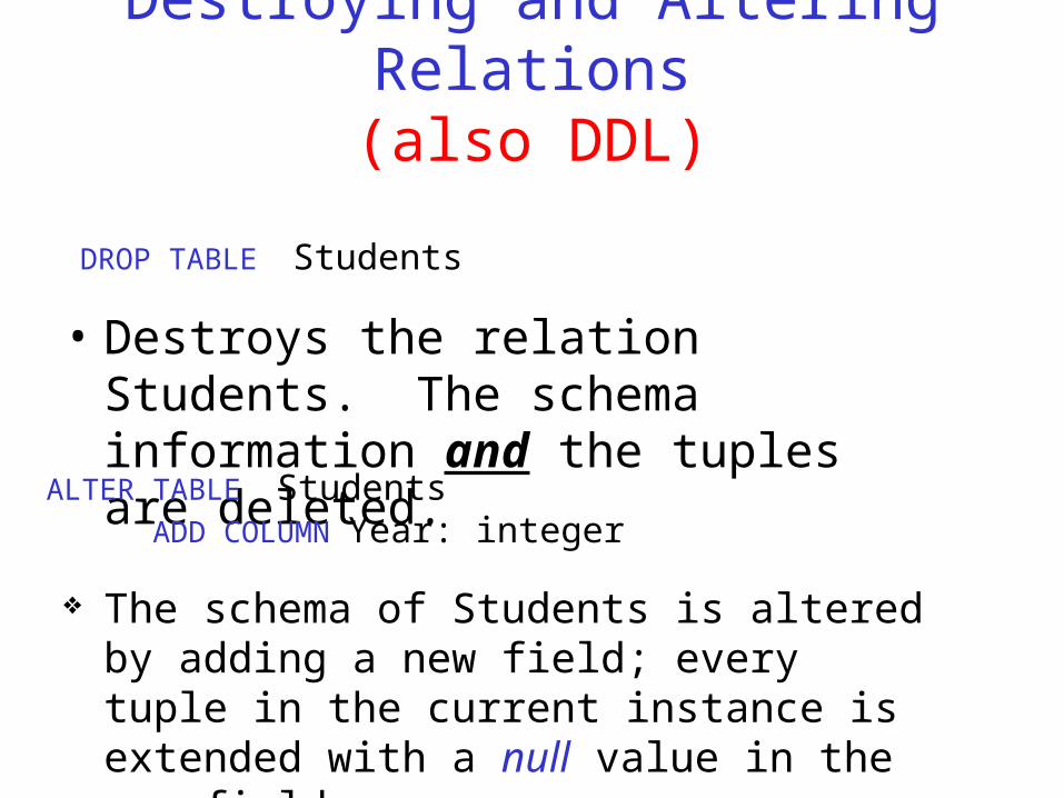
Destroying and Altering Relations(also DDL)
• Destroys the relation Students. The schema information and the tuples are deleted.
DROP TABLE Students
The schema of Students is altered by adding a new field; every tuple in the current instance is extended with a null value in the new field.
ALTER TABLE Students ADD COLUMN Year: integer
Adding and Deleting Tuples
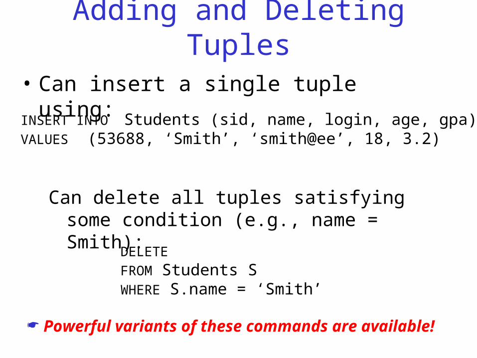
• Can insert a single tuple using:
INSERT INTO Students (sid, name, login, age, gpa)VALUES (53688, ‘Smith’, ‘smith@ee’, 18, 3.2)
Can delete all tuples satisfying some condition (e.g., name = Smith):
DELETE FROM Students SWHERE S.name = ‘Smith’
Powerful variants of these commands are available!
Integrity Constraints (ICs)
• IC: condition that must be true for any instance of the database; e.g., domain constraints. Which we have already seen in the CREATE verb.– ICs are specified when schema is defined.– ICs are checked when relations are modified.
• A legal instance of a relation is one that satisfies all specified ICs. – DBMS should not allow illegal instances.
• If the DBMS checks ICs, stored data is more faithful to real-world meaning.– Avoids data entry errors, too!
Primary Key Constraints
• A set of fields is a key (strictly speaking, a candidate key) for a relation if :1. (Uniqueness cond.) No two distinct tuples can have
same values in the key field (may be composite)2. (Minimality cond.) The Uniqueness condition is not
true for any subset of a composite key.– If Part 2 is false, it’s called a superkey (superset of a
key)– There’s always at least one key for a relation, one of
the keys is chosen (by DBA) to be the primary key. (primary record identification key or look-up key)
• E.g., sid is a key for Students. The set {sid, gpa} is a superkey.
Entity integrity
• No column of the primary key can contain a null value.
Foreign Keys, Referential Integrity
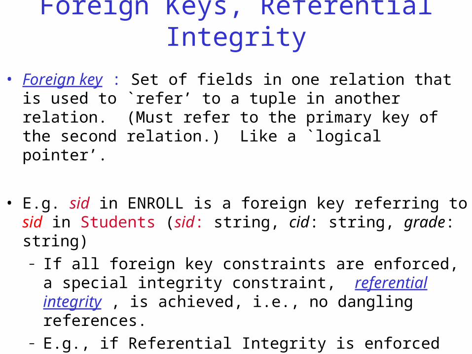
• Foreign key : Set of fields in one relation that is used to `refer’ to a tuple in another relation. (Must refer to the primary key of the second relation.) Like a `logical pointer’.
• E.g. sid in ENROLL is a foreign key referring to sid in Students (sid: string, cid: string, grade: string)– If all foreign key constraints are enforced, a special
integrity constraint, referential integrity , is achieved, i.e., no dangling references.
– E.g., if Referential Integrity is enforced (and it almost always is) an Enrolled record cannot have an sid that is not present in Students (students cannot enroll in courses until they register in the school)
Foreign Keys in SQL
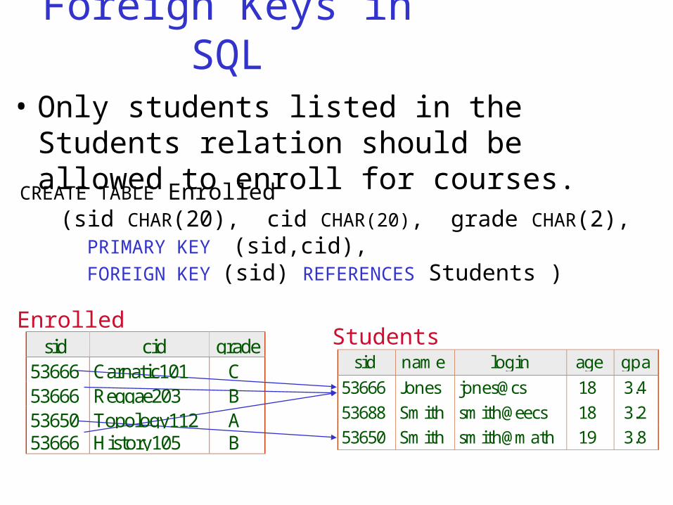
• Only students listed in the Students relation should be allowed to enroll for courses.
CREATE TABLE Enrolled (sid CHAR(20), cid CHAR(20), grade CHAR(2), PRIMARY KEY (sid,cid), FOREIGN KEY (sid) REFERENCES Students )
sid cid grade53666 Carnatic101 C53666 Reggae203 B53650 Topology112 A53666 History105 B
Enrolled
sid name login age gpa
53666 Jones jones@cs 18 3.453688 Smith smith@eecs 18 3.253650 Smith smith@math 19 3.8
Students
Enforcing Referential Integrity
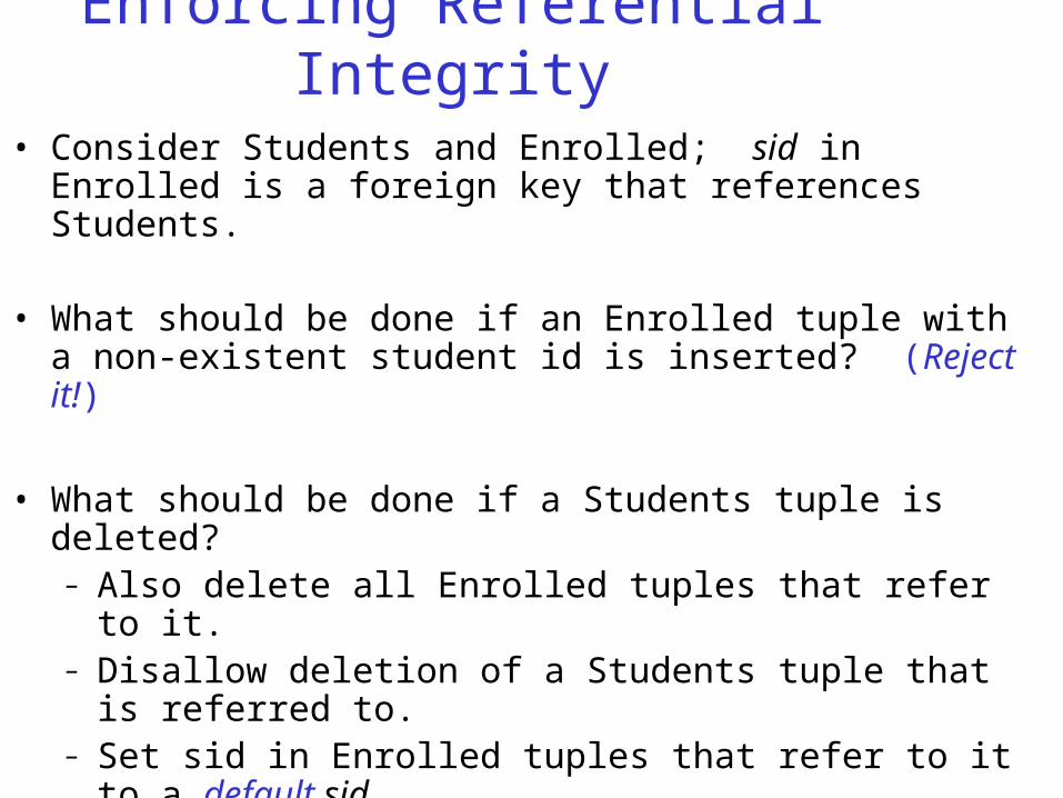
• Consider Students and Enrolled; sid in Enrolled is a foreign key that references Students.
• What should be done if an Enrolled tuple with a non-existent student id is inserted? (Reject it!)
• What should be done if a Students tuple is deleted?– Also delete all Enrolled tuples that refer to it.– Disallow deletion of a Students tuple that is referred
to.– Set sid in Enrolled tuples that refer to it to a default
sid.– (In SQL, also: Set sid in Enrolled tuples that refer to
it to a special value null, denoting `unknown’ or `inapplicable’.)
• Similar if primary key of Students tuple is updated.
Referential Integrity in SQL/92
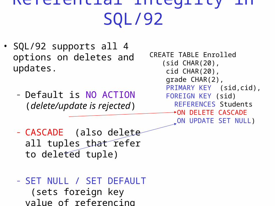
• SQL/92 supports all 4 options on deletes and updates.
– Default is NO ACTION (delete/update is rejected)
– CASCADE (also delete all tuples that refer to deleted tuple)
– SET NULL / SET DEFAULT (sets foreign key value of referencing tuple)
CREATE TABLE Enrolled (sid CHAR(20), cid CHAR(20), grade CHAR(2), PRIMARY KEY (sid,cid), FOREIGN KEY (sid) REFERENCES Students
ON DELETE CASCADEON UPDATE SET NULL)
Where do ICs Come From?• ICs are based on the semantics of the real-
world enterprise that is being described in the database relations. I.e., users decide, not DB experts! Why?
• We can check a database instance to see if an IC is violated, but we can NEVER infer that an IC is true by looking at the instances.
• An IC is a statement about all possible instances! It is not a statement that can be inferred from the set of existing instances.
• Key and foreign key ICs are the most common; more general ICs supported too.
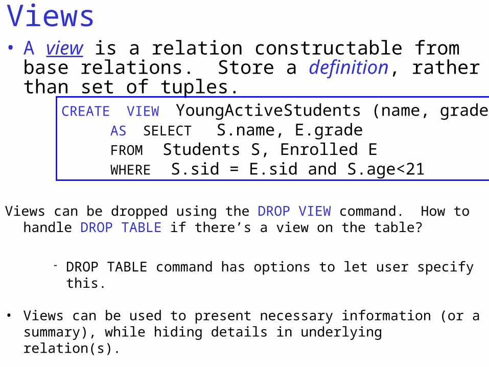
Views• A view is a relation constructable from base
relations. Store a definition, rather than set of tuples.
CREATE VIEW YoungActiveStudents (name, grade)AS SELECT S.name, E.gradeFROM Students S, Enrolled EWHERE S.sid = E.sid and S.age<21
Views can be dropped using the DROP VIEW command. How to handle DROP TABLE if there’s a view on the table?
DROP TABLE command has options to let user specify this.
• Views can be used to present necessary information (or a summary), while hiding details in underlying relation(s).
– Given YoungStudents, but not Students or Enrolled, we can find students s who are enrolled, but not the cid’s of the courses they are enrolled in.
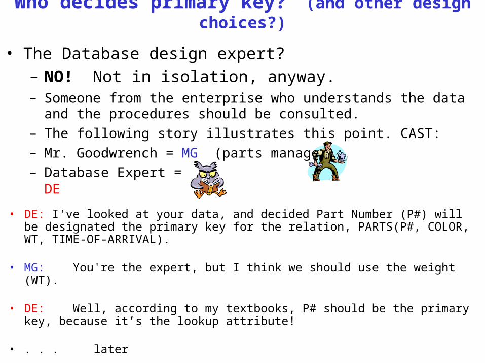
Who decides primary key? (and other design choices?)
• DE: I've looked at your data, and decided Part Number (P#) will be designated the primary key for the relation, PARTS(P#, COLOR, WT, TIME-OF-ARRIVAL).
• MG: You're the expert, but I think we should use the weight (WT).
• DE: Well, according to my textbooks, P# should be the primary key, because it’s the lookup attribute!
• . . . later
– Database Expert = DE
• The Database design expert?– NO! Not in isolation, anyway.– Someone from the enterprise who understands the data and
the procedures should be consulted.– The following story illustrates this point. CAST: – Mr. Goodwrench = MG (parts manager);
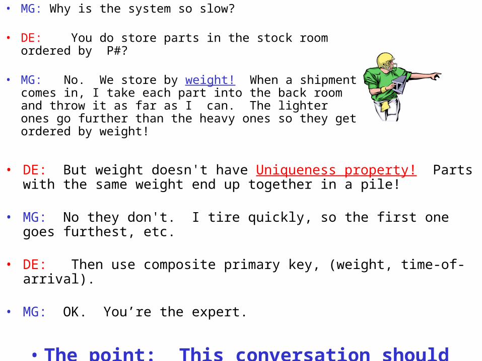
• MG: Why is the system so slow?
• DE: You do store parts in the stock room ordered by P#?
• MG: No. We store by weight! When a shipment comes in, I take each part into the back room and throw it as far as I can. The lighter ones go further than the heavy ones so they get ordered by weight!
• DE: But weight doesn't have Uniqueness property! Parts with the same weight end up together in a pile!
• MG: No they don't. I tire quickly, so the first one goes furthest, etc.
• DE: Then use composite primary key, (weight, time-of-arrival).
• MG: OK. You’re the expert.
• The point: This conversation should have taken place during the 1st meeting.


![Data Warehousing and Data Mining for the Management of ... · data into the Data Warehouse[11]. Analysis and Restitution of Data: Data from a Multi-Dimensional Database is queried](https://img.pdfslide.us/doc/110x75/5f1aac6e06f7d03e834d9970/data-warehousing-and-data-mining-for-the-management-of-data-into-the-data-warehouse11.jpg)