Embed Size (px)
Citation preview

LEVEL,1r
TECHNICAL REPO BRL-TR-ýJ2335i4
(Supersedes IMR No. 696) t
A SIMPLE METHOD FOR PREDICTING MUZZLE
BRAKE-EFFECTIVENESS AND - -
BAFFLE-SURFACE PRESSURE /J
Kevi n S. FFanse J ELECTE~AUS 0 3 1981
"W.JuN.8.. E
kj" 7_ýto "ý1
US ARMY ARMAMENT RESEARCH AND DEVELOPMENT COMMANDBALLISTIC RESEARCH LABORATORY
ABERDEEN PROVING GROUND, MARYLAND
-Approved, for public release; distribution unlimited.
0.
C..*

Pr
Destroy this report when it is no longer needed.Do not return it to the originator.
Secondary distribution of this report by originatingor sponsoring activity is prohibited.
Additional copies of this report may be obtainedfrom the National Technical Information Service,U.S. Department of Commerce, Springfield, Virginia22161.
i'
The findings in this report are not to be construed asan official Department of the Army position, unlessso designated by other authorized documents.
The use of titide names or manufactuzrers' •me in thiu rportdoea not ons titute indorsement of anuy conmerciazl product.

UNCLASSIFIEDSECURITY CLASSIFICATION OF THIS PAGE (When Dotl Entered)
SREPOR DOCUMENTAT'I•N PAGE READ INSTRUCTIONSBEFORE COMPLETING FORM,
1. REPORT NUMBER " 2. GOV/T ACCESSION NO.1 3 RECIPIENT'S CATALOG NUMBER
4. TITILE (and Subtitle) 5 TYPE 10F REPORT & PERIOD COVERED
A SIMPLE METHOD FOR PREDICTING ý.lJZZLE BRAKE Final
EFFECTIVENESS AND BAFFLE-SURFACE PRESSURE 6 PERFORMINC ORG. REPORT NUMBER
7. AUTHOR(@) S. CONTRACTORGRAN't NUMBER(o)
KEVIN S. FANSLER
9. PERFORMING ORGANIZATION NAME AND ADDRESS I0 PROGRAM ELEMENT, PROJECT, TASK
U.S. Army Ballistic Research Laboratory AREA & WORK UNIT NUMBERS
(ATTN: DRDAR-BLL) RDT&E 16161102A1H43Aberdeen Proving Ground, Maryland 21005
Ii. CONTROLLING OFFICE NAME AND ADDRESS 12. REPORT DATE
U.S. Army Armament Research & Development Command JUNE 1981U.S. Army Ballistic Research Laboratory 13 NUMBEROF PAGES
(ATTN: DRDAR-BL) Aberdeen Proving Ground, MD 21005 3914. MONITORING AGENCY NAME & ADDRESS(If different from Controlling Office) '.. SECURITY CLASS. (of thie report)
Unclassified
15a. Dý-CLASSI FICATION/DOWNGRADINGSCHEDULE
16. DISTRIBUTION STATEMENT (of thli Report)
Approved for public release; distribution unlimited.
17. DISTRIBUTION STATEMENT (of the abetract entered In Block 20, If different from Report)
18. SUPPLEMENTARY NOTES
This report supersedes Interim Memorandum Report No. 696 dated December 1980.
19. KEY WORDS (Continue on reveree aide If neceessry and identify by block nu.miber)
Muzzle BrakesJet FlowsBrake Efficiency
0. ABT-RACT (Cothan -tee ef N ceay am Idervify by block number) (ner)-The objective of this work is to produce a simple method for calculating loaddistributions on muzzle brake baffles during the firing process. With the loaddistribution known, the muzzle-brake effectiveness expression can be obtainedand easily evaluated. The approach is to use a simple model for the muzzle-jettflow to predict the pressure on the baffle. The baffle is located in the super-sonic jet core during much of the gun-exhaust cycle. This impinging flow ontothe baffles is approximated by adopting a source flow model. Newtonian theory(Continued).
DDFIR" I3T EDITON OF 1; NOav s IS OBSOLETE.
DO 143 Em UNCLASSIFIED
SECURITY CLASSIFICATION OF THIS PAGE (Wrten Data Entered)

,INCLASFTF.DSECURITY CLA3S~tlCATIOrN OF THIS PAGE(Whumn Data Entorod)
20. ABSTRACT (Continued):
*is used to predict the resulting pressures on the baffles. The theoreticalresults compare well with previous published experimental results. With thismodel, brake-effectiveness variation with parameter changes can be simplyobtained for most gun systems.
UNCLASSIFIED
SECURITY CLASSIFICATION OF THIS PAGE(1Wen Data Entered)

TABLE OF CONTENTS
Page
LIST OF ILLUSTRATIONS ............ ....................
I. INTRODUCTION .... ............... . . . . . . .. . . . 7
Ii. MODEL FOR THE PRESSURE AND IMPINGING FLOW ONTO THEBAFFLE ................................ .............. 8
III. DEVELOPMENT OF MUZZLE-BRAKE MOMENTUM-INDEX EXPRESSION ... 13
IV. DISCUSSION ..................... ........................ 15
V. SUMMARY AND CONCLUSIONS .......... .................. ..16
RE.ýERENCES ................. ........................ ..25
APPE,'DIX A. •UZZLE-BRAKE EFFECTIVENESS DEFINITIONS . ... 27
APPENDIX B. PROGRAM FOR CALCULATING THE PRESSURE AND THEMOMENTUM INDEX ....... ............... .. 31
LIST OF SYMBOLS .............. ...................... ..33
DISTRIBUTION LIST .......... ..................... .. 35
Acce.sso- For
VNT!S GRA&IDTiC TA$
By-.. ...
Su
[3

LIST OF ILLUSTRATIONS
Figure Page
1 Double-Baffle Muzzle Brake with Instrumentation .......... 17
2 Flow Structure of the Gun Blast ..... ............... ..17
3 Effect of Partially Closing a Brake ..... ............. .18
4 Streamlines and Isoproperty Lines for Steady Jet ........ .18
5 Some Centerline Property Distributiens for the Jet Core. . .19
6 Illustrating Source Flow Impin- t onto Baffle ........ .19
7 Illustrating Cone-Section Contro. ,lume Located nextto the Baffle Surface .......... ................... .20
8 Jet Property Function on Boreline ..... .............. ..20
9a Comparison of Optimized Model with Experiment(z = 1 caliber) ............ ...................... ..21
9b Comparison of Optimized Model with Experiment(z = 1.5 calibers) ......... .................. ...
9c Comparison of Optimized Model with Experiment(z 4 calibers) ................ ........... ......... 22
10 Momentum Index Comparison for Different Muzzle-ExitMach Numbers ............... ...................... .22
11 Momentum Index versus Baffle Angle; Comparison BetweenTheory and Experiment .......... ................... .23
12 Momentum Index versus Baffle Angle for Different BaffleDistances .............. ......................... .23
13 Momentum Index versus Baffle Position; Comparison BetweenTheory and Experiment .......... .................. .24
11ECEDNG PAGE LANK-NOT Faii

I. INTRODUCTION
A muzzle brake, Figure 1, is used to reduce the recoil of the gunthus allowing a lighter gun cirriage. The impinging gun-exhaust plumeexerts counterforces on the baffle surfaces thus reducing the recoilimpulse. The cowls attach the baffles to the gun but may also affecttihe momentum imparted to the muzzle brake. The objective of this workis to calculate the muzzle-brake momentum index by a simple method.The momentum index value is a measure of the counter impulse given thebrake compared to the gas ejection impulse and thus is a measure of thebrake efficiency or effectiveness.
This work stems from the muzzle-brake investigations of Oswatitsch1 ' 2
and Simith 3 '4o Oswatitsch shows that the exhaust flow impinging upon abaffle may be approximated by a quasi-steady jet. Smith '4 also makesthis assumption. Schmidt and Shear s have confirmed this hypothesis byutilizing optical techniques, Figure 2 displays the structure of theflow from the muzzle. Immediately after the projectile leaves themuzzle, the gases are freed to expand. The free-air blast forms andtravels rapidly with the contact surface and Mach disc following. Inthe supersonic core, the gases expand from the high pressures at themozzle to very low pressures near the barrel shock. Even through theMach disc or blast front is moving, the region in the supersonic coreapproximates the flow in a steady jet with the same muzzle-exit condi-tions, With the baffle p3aced one to a few calibers away from the
1. K. Oswatitsch., "Intermedia-ce Ballistics, " DVI R 358, DeutschenVersuchsanstalt fur Luft-unca '7aumfahrt, Aachen, Germany,June 1964., (UNCLASSIFIED). AL 473 249.
2. K. Oswatitsch, "Flow Research to Improve the Efficiency of MuzzleX! Brakes, Part I-II, " in Muzzle Brakes, Yolvme II: Theory,
E. Hcmner (ed.), Franklin Inr2titute, Phiaea lphia., PA, 1949.
3. F. Smith., "Model Experiments on Muzzle Brakes, " RARDE R 9/66,Royal Armament Research and Development Establishment, F( -tHalstead, U.K., 1966. (UNCLASSIFIED). AD 48? 121.
4. F. Smith., "Model Experiments on Muzzlo Brakes, Pc- t III: Measurementof Pressure Distribution," RARDE R 3/68, Royal Arr777ent Researchand Development Establishment, Fort Halstead, U.K.., L68.(UNCLASSIFIED). AD 845 519.
5. E. M. Schmidt and D. D. Shear, "Optical Measurement o Z1&4l'eBlast," AIAA j., Vol. 13, No. 8, August 1975, pp. 108".-1. 91.
7

muzzle, the baffle would be in the supersonic core for most o0 the gunexhaust phase. Thus, the core flow impinging uIon the baffles primarilydetermines the momentum index.
In the present work, we first apply a simple theory for predictingpressures on the baffles given the impinging flow. W th Schmidt, et al6,and Smith 3 ' 4 , we utilize Newtonian theory. Next, we construct a simplemodel for the flowv in the muzzle-jet plume assuming a -upersonic sourceflow. With these assumptions, we then vary the source location so thatthe theoretical overpressure curve can be fitted to the experimentaldata of Schmidt, et a1 6 . With the optimum source location established,the expression for the pressure can be integrated and a simple closed-form expression for the momentum-index of the brake is obtained.
The resulting model is applicable to most gun systems althoughthe present study does not take into account how the efficiency varieswith the amount of enclosure associated with the cowls. HIowever,Smith's 3 ' 4 experiments show the momentum-index changes little for smallamounts of enclosure. Figure 3 shows that when 5, the angle that thedisc is inclined from the radial plane, is equal to zero, (flat aiscs),the momentum index increases monotonically and a.,,1st linearly as theenclosure _Uue for the cowls is increased. When che cowls encloseone-half of the surrounding space, the momentum-index increase is about10%. WVhen the angle 6 is greater than 200, the moientum index valuesgo both below and above the value for the fully open brake. This maxi-mum excursion when surrounding space is less than half closed by cowlsis a little more than S%.
I1. MODEL FOR THE PRESSURE AND IMPINGING FLOW ONTO THE BAFFLE
The pressure on the baffle surface is calculated by Newtonian flowtheory, Consider that the flow is incident on the baffle surface atthe angle 6 and with the local fluid velocity V. As fluid strikes thesurface, the perpendicular component of momentimi is dissipated but thevelocity component tangent to the surface is unchangeo. The resultingoverpressure equation can be shown to be
ps-p = pV2 sin 2 (i)
6. E. M. Schmidt, E. J. Gion, and K. S. FansZer, "Measurement ofMuzzle Blast and Its Impingement Upon Surfaces," AI.M _2th Fluidand Plasma Dynanics Conference, Williamsburg, VA, July 1979,AIAA Paper 79 - 1550.
8

Here ps is the pressure on the baffle and p is the local value of the
pressure in the flow field. Schmidt, et a1 6 , applied this theory forgun-exhaust flow impinging upon a disc-baffle and obtained good agree-ment with experiment. They approximated the supersonic-core flow ontothe baffle as a steady-jet method-of-characteristics calculation 7 .Smith 3 considers "that the flow which would normally pass through thedisc is simply removed from the flow picture with a correspondingremoval of its thrust component." This view, for a straight disc,is equivalent to the application of Newton's flow theory, Nevertheless,for conical baffles Z6 > 0), the two resulting expressions are somewhatdifferent.
As discussed earlier, the flow onto the brake can be approximatedas a steady supersonic jet-core flow with muzzle-exit conditions forthe time of interest. Figure 4 shows a steady supersonic core flow
generated by a melhod-of-characteristics calculation 7 . The linesgoing away from the muzzle are streamlines. The other set of lines areisoproperty lines along which the pressure, temperature and Machnumber are constant. A feature of this flow structure permits asimplifying approximation. A short distance downstream of the muzzle,the streamlines tend to straighten out althou{'h still possessing somesmall curvature. Such a flow is reminiscent of the simpler supersonicsource flowwhich would have straight streamlines emanating from thecenter with the isoproperty i4nes represented by concentric circles.The source flow is defined if the position of the origin and the gas-dynamic properties at a given radius are known.
Using Newtonian flow theory and the source flow approximation, wecan derive a simple expression for the pressure on the surface of abaffle. We can start by restating that the flow field of a sourceflow can be determined if we know the position of the source pointand the gasdynamic properties at a given radius. We will use thecenterline properties to find the flow characteristics elsewhere inthe field. We use a method of characteristics (4OC0 scheme to generatethe Mach number distribution along the bore]ine once and for all. Tnisdistribution approximates sufficiently well the distributions for awide range of muzzle-exit conditions of iinterest. Figure 5 shows theMach number distribution and other centerline properties for the jetcore. Here the subscripts j and c denote the muzzle exit conditionsand the local boreline coaditions respectively. The symbols M and ydenote the Mach number and the specific heat rati, respectively.
7. A. R. Vick, E. H. Andrews, J. S. Pennard, and C. B. Craidon,"Comparison of Experimental Free-Jet Boundaries wtth TheoreticalResults Obtained with the Method of Characteristics.," NASATechnical Note D-2327, June 1964 (NTIS N64-23032).
9
The distance along the centerline is expressed in calibers. in fact,
the distances in this paper will always be expressed in calibers.With the Mach number distribution and the muzzle exit conditions known,we can calculate the gasdynamic properties at any selected point onthe centerline.
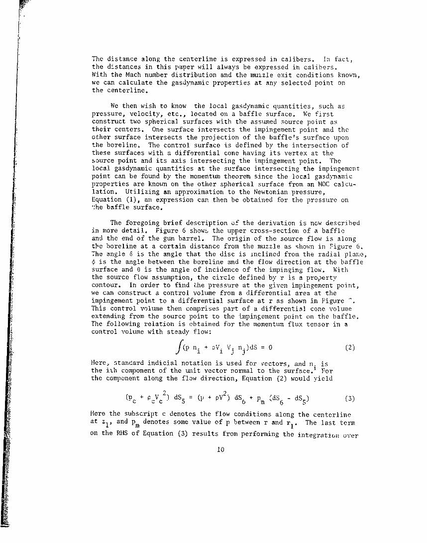
We then wish to know the local gasdynamic quantities, such aspressure, velocity, etc., located on a baffle surface. We firstconstruct two spherical surfaces with the assumed source point astheir centers. One surface intersects the impingement point and theother surface intersects the projection of the baffle's surface uponthe boreline. The control surface is defined by the intersection ofthese surfaces with a differential cone having its vertex at thesource point and its axis intersecting the impingement point. Thelocal gasdynamic quantities at the surface intersecting the impingementpoint can be found by the momentum theorem since the local gasdynamicproperties are known on the other spherical surface from an MOC calcu-lation. Utilizing an approximation to the Newtonian pressure,Equation (1), an expression can then be obtained for the pressure on:he baffle surface.
The foregoing brief description of the derivation is now describedin more detail. Figure 6 shows the upper cross-section of a baffleand the end of the gun barrel. The origin of the source flow is alongtbe boreline at a certain distance from the muzzle as shown in Figure 6.The angle 6 is the angle that the disc is inclined from the radial plane,Sis the angle between the boreline and the flow direction at the bafflesurface and e is the angle of incidence of the impinging flow. Withthe source flow assumption, the circle defined by r is a propertycontour. In order to find i.he pressure at the given impingement point,we can construct a control volume from a differential area at theimpingement point to a differential surface at r as shown in Figure •.This control volume then comprises part of a differential cone volumeextending from the source point to the impingement point on the baffle.The following relation is obtained for the momentum flux tensor in acontrol volume with steady flow:
_ f(p + V n.)dS = 0 (2)S- 33
Here, standard indicial notation is used for vectors, and n. isthe ith component of the unit vector normal to the surface.' Forthe component along the flow direction, Equation (2) would yield
(Pc + PcVc2) dS5 (p+pV2) dS6 + Pm &dS6 - dS5 ) (3)
Here the subscript c denotes the flow conditions along the centerlineat zl, and pm denotes some value of p between r and rI. The last term
on the RHS of Equation (3) results from performing the integration over
10

2the sides of the control surface. Since dS is proportional to r andby the law of sines, r 1/sin a = r /sin 0:
dS5 sin2e
dS6 sin2a
Equation (3) becomes, using the above equation and neglecting therelatively small RHS second term:
2 sin2p + pV (p + P V ) (4)
c c c .2sin ca
Now in the flow of interest, we could approximate Equation (1) by
2 2p (p + pV) sine (5)
For baffle distances greater than 1 caliber from the muzzle, the errorin the approximation to Equation (1) is small for the baffle configu-rations of interest. Substituting Equation (4) into Equation (5), weobtain in terms of € and 6,
2 4 2Ps = (P + PcVc2) cos (4-6) /cos 6 (6)
To transform Equation (6) to an easily calculated form, divide throughby p.. Multiplying and dividing through by pj, we obtain
p5 p p.ps 0 Ps P0 (7)P. Pj Pý'
The value of pj/p. is estimated by interior ballistic theory, In terms
of the Mach number of the flow, Equation (6) becomes, using Equation (7)together with the ideal gas law and the isentropic relations:
p p.Y A
!s (I+L-1 M 2 )Y-1 F cos (W-O) (8)P. P cos6
where M. is the jet-exit Mach number andJ
11

(1 + LI 2C-()2
The value of F as a function of distance in calibers along theboreline is shown in Figure 8. These values of F were calculated witha method-of-characteristics numerical scheme. It is found that F hasnegligible dependence on expected values of the muzzle-exit conditionsM., y and pj/p. for baffle positions of interest. For this analysis,
F will be assumed to be independent of these muzzle-exit conditions.The thickness of the line comprises the differences observed fory- = 1.2 and y = 1.3. These values of y should cover the expectedrange of y for propellant gases. Thus F is applicable to almost allgun systems.
6Utilizing Schmidt et al , experimental data, the source point
position may be varied to obtain optimum agreement with Equation (8).The expression for r as a function of z is the following:
2r = 0.101z + 0.528z + 0.271 + R tan 6 (10)
Hlere, R1 is the projectile hole diameter expressed in calibers.
Figuie 9a gives the overpressure distribution on a disc that is located1 caliber from the muzzle. The experiment used a disc with pressuregages inserted at half-caliber intervals along the radius of the disc,Comparisons between the experir.ent and the curve fit show good agreement.Figure 9b shows the comparison at 1.S calibers. Figure 9c gives thecomparison for the baffle positioned at 4 calibers. Here theagreement is not as good. It is impossible to move the source to aposition to give a better fit. The calculated pressures are lowerat the smaller radii, which agrees with the observations of Schmidtet al 6 .
Although the model has been applied to a 20mm gun, the universalityof the plume-flow characteristics permits the application of Equation (8)to most weapons. The model would appear to be less applicable as oneencounters higher jet-exit Mach numbers. From the Mach contour linesand streamlines generated by the MOC calculations, the flow patternsindicate that the equivalent source would need to be moved farther fromthe muzzle as the jet-exit Mach number increased. Compared to thesonic jet, this would lower the pressures and also increase the fall-off rate of the pressures with increasing radius.
12

III. DEVELOPMENT OF MUZZLE-BRAKE MOMENTUM-INDEX EXPRESSION
As discussed in the Appendix, we have chosen the momentum indexto be
I-IlT (11)
G
Here I is the recoil impulse of the gun-barrel with a bare muzzle, I/is the recoil impulse of the gun-barrel with the muzzle brake and G isthe impulse given the bare-muzzle gun by the propellant gases. The gasimpulse is essentially the time integral of the momentum flux passingthe muzzle face of the gun. During the major portion of the gun-emptying phase, the ratio of the numerator to the denominator is approxi-mately a constant, as shown in Appendix A. Thus, Equation (11) is wellapproximated by replacement of the time integrals by their correspondingintegrands,}r
(ps-p.) n zdS
2 (12)(p.+pjV. )A.
Here dS is a differential surface on the muzzle brake and n is the zcomponent of the unit vector normal to the surface. The denominatorof Equation (12) is the thrust, T, generated by the propellant gas onthe weapon and the numerator is simply T-T' where T' is the thrust ofthe propellant gases with the muzzle brake in place. Equation (12)is then
T/
If T' = 0, then all the exhaust thrust is canceled and n = 1. Themomentum index thus gives a measure of the effectiveness or efficiencyof the brake. Larger values of n indicate a more effective brake.
From Figure 6, we cai, show that dS in terms of ý and r is
dS = (2rr2 cos 2 sin4 d4)/cos3 (ý-6) (13)
Substituting Equations (8) and t13) into Equation (12) with the valueof p. assumed small, we obtain
n = 2H cos6fssin(cos( 6)d4 (14)
where Y--
4r 2 (1 + Li M.2 )' 1 FH - 2 2(1)
I + yMj 2
13

Integration of Equation (14) yields the momentum index expression
T1= H cos6 cos6 (sin 2m - sin2 n) +
sin6 [(m - costM sinpM) (ýn - cos n sin ; (16)
Here the subscript "Im" refers to the maximum value of the angle and "n"refers to the minimum value of the angle subtended by the muzzl. brake.Of course, the total force on the baffle can be obtained by multiplying
2Sby pj (1 + yMj )A.
In keeping with the spirit of the preceding approximations andin view of the accuracy expected from this approach, a sufficientlygood approximation to the calculated H is achieved using the followingequation
H = 0.22 (z + R1 tan6) + 1.07 (1-)
The value of H is quite sensitive to the prescription for the sourcepoint placement. If the source point is moved toward the fixed baffle,the value of H is decreased. Nevertheless, the multiplicand of H inEquation (16) would be increased,thus partly offsetting a possibleerror made in source placement.
To illustrate how to use Equation (16) to calculate the momentumindex, a program in BASIC is presented in Appendix B.
It should be noted that F can now be expressed in terms of Z, 6and the muzzle exit conditions. From Equation (15), we have
(I + NM 2
F = -- Y(18)
4r2 (1 + I Mj2 ) Y-14r(1 2 j
The value r is expressed in terms of z and 6 according to Equation (10)and H is found from Equation (17). Thus the expression for thepressure, Equation (8), can now be found without resorting to the useof graphs or extensive calculations.
14

IV. DISCUSSION
It is of interest to see how far this analysis may be extended.For a variation of y from 1.2 to 1.3, the value of H varies 1% forsonic jet-exit gas velocities. This result is obtained using a method-of-characteristics calculation with Equation (15). Furthermore, theMach contours and lines of flow inclination vary little in this rangeof y. Thus, we should be able to use Equation (16) for 1.2 < y < 1.3.The value of H varies more with the parameter M.. The value of H3
increases by a factor of 1.35 from M. = 1 to M. = 1.8 and the optimum3 3
source-point location for agreement with experiment probably also changes.To see how the momentum index varies with M., we can utilize the approachof Schmidt 6 which describes the flow by MOC3 calculations. Figure 10shows a comparison of n for different values of Mj at z = 1,5. Theefficiency is found to vary little for the two values of M. for discs of
different radii. Thus, the model can at least be extended to the M.
range 1 to 1.8 for baffles in the vicinity of z = 1.S. Although theinsensitivity of H to M. undoubtedly occurs at other values of z, there
may be less agreement than was displayed in Figure 10. For most cases,the value of M. probably declines to near 1 early in the exhaust phase,
so that the properly weighted value for M. in Equation (12) would be3
close to 1. Taking into account this canceling behavior and theweighted vaji. for Mi, the error should be small in assuming a sonic
jet for most cases.
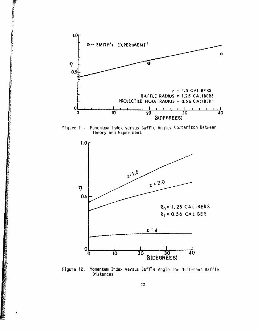
The model can also be compared to experiment for varying baffleangles. Figure 11 is a comparison between Smith's 3 experiments andthe theory for baffles placed at z = 1.5. The efficiency increaseswith the baffle angle partly for the reason that the baffle is inter-cepting more of the flow. Smith's experiment was run for y = 1.67but Smith indicates that the results should be near the propellant-gasresults where y = 1.25.
It appears that the source-flow model can give approximate pre-dictions of the momentum index for different design parameters ofinterest. Figure 12 explores the influence of the baffle angle, 6,
Z on the momentum index for different values of baffle position. Theouter and inner baffle radii are held constant. The momentum indexincreases little for larger values of 6 at z = 4. In fact, the momentumindex decreases slightly from 6 = 300 to 6 = 400.
It is of interest to find the distance for a certain diameter discthat would produce the highest momentum index. This might not be thebest distance for placement since the brake mass and strength alsohave to be taken into consideration. Figure 13 shows hown varies with z for different radii of discs using the present model.
15

r
The model results are compared with the experimental results of Smith.For the limited amount of data available, the agreement between experi-ment and theory is good. Both the model and experiment show that ndecreases as z decreases for small values of z. This occurs because anincreasing amount of the flow is going through the projectile hole.At large values of z, less of the flow intercepts the brake baffle asz increases. The maximum value of n occurs at larger values of z asthe disc radius increases. The effect of the projectile hole lossbecomes apparent at larger values of z as the radius of the disc isincreased. The maximum values for the experimental curves occur atslightly larger values of z than the model predicts.
V. SUMMARY AND CONCLUSIONS
A simple method for calculating the pressures on the baffle andthe impulse given the muzzle brake during firing has been developed.The method utilizes Newtonain flow theory and a source flow whoseorigin is moved with baffle distance to provide optimum agreement withexperimental results. Although the method was developed using oneweapons system, the modcl can be applied to most gun systems. Appli-cation of the method requires knowledge of the size of the disc and pro-jectile hole, distance of the projectile hole from the muzzle and theangle 6. Additionally, to obtain baffle pressures, knowledge of themuzzle-exit conditions is required. The momentum index is calculatedusing a simple formula. The results agree well with an independentexperiment o
Although the method was developed specifically for disc bafflesand sonic muzzle jets, the method can be extended to more complex muzzle-brake shapes and often to muzzle flow with initial supersonic exitconditions. Some baffle shapes could be approximated by a collectionof discs and sections of discs. For disc baffles, Smith 3 indicatescowling enclosing the surrounding space by less than one-half seems tochange the momentum index by only a small amount. Nevertheless,comparing the present method's calculations with results 8 for rectangularbaffle plates using top and bottom plates, we find that the presentmethod's momentum index values are lov'er. The average values obtainedby the present method need to be multiplied by 1.3 to agree with theaverage experimental values. It ½s assumed that this discrepancy iscaused by the effect of the top and bottom plates.
16S

r•
4
Figure i. Double-Baffle Muzzle Brake with Instrumentation
BLAST WAVE FRONT
AI GASES •
SUPERSONIC \
Figure 2. Flow Structure of the Gun Blast
17

1.2 q0 = VALUE OF " FOR FULLY OPEN BRAKEf VALUE OF v FOR PARTIALLY CLOSED BRAKE
f FRACTION OF CIRCUMFERENCE CLOSED TO FLOWB=0°
--.--. 20"R0 = 1.5 CALIBERS
1.1 R1 0.56 CALIBER
7?ff
0.9
Figure 3. Effect of Partially Closing a Brake
CONTACT SURFACE BARREL SHOCK--7
STREAMLINES 7
Figure 4. Streamlines and Isoproperty Lines for Steady Jet
18

10
MP c
i ~10.2 .
Mi- 1 .c 00yj -- .y 1.251 PC p|
L Pi/poz 50o
io3 I 0I I0 1 2 3 4 5 6
z (CALIBERS)
Figure 5. Some Centerline Property Distributions for the Jet Core
MUZZLE/ r
SOURCE POINT
Figure 6. Illustrating Source Flow Impingement onto Baffle
19

dS
ds60
rd5
a
Figure 7. Illustrating Cone-Section Control VWlime Located next to theBaffle Surface
A F
L
P,.:)I - - I . . I . , I I
0 1 2 3 4 5 6ZI (CALIBERS)
Figure 8. Jet Property Function on Borelit.c"
20

2
-u
Uj
SA.-,SCHMIDT, GION AND FANSLER
DISC IS 1 CALIBER FROM MUZZLE
0 1 1 1 I I0 5 10 15 20 25
(P-PaI) / PCo
Figure 9a. Comparison of Optimized Mode! with Exp~riment (z 1 caliber)
2
LU
-A,.SCHMIDT, GION AND FANSLERDISC IS 1.5 CALIBERS FROM MUZZLE
0 I I I I
0 5 10 15 20
(Pc-P0) / Pc0
Figure 9b. Comparison of Optimized Model with Experiment (z 1.5 calibers)
21

4-
3- •• -
Uj
A- SCHMIDTGION AND FANSLER
DISC IS 4 CALIBERS FROM MUZZLE
010 I I 1 10 1 2 3 4 5 6
(P-Pc) / Pco
Figure 9c. Comparison of Optimized Model with Experiment (z = 4 calibers)
-• ~0.6-
0.41
77r Mj :1.8
0.2)Z 1.5 CALIBERS
0 1__ _ _ _ _ _ _ _ _ _ _ _ _ _
0.5 1.0 1.5OIW DIAM1TER
Figure 10. Momentum Index Comparison for Different Muzzle-Exit MachNumbers
22
1.0
0-' SMITH's EXPERIMENT3
71
z = 1.5 CALIBERSBAFFLE RADIUS x1.25 CALIBERS
PROJECTILE HOLE RADIUS = 0.56 CAL IBER'0- ,~~I,~
010 20 30 40B(DEGREES)
Figure 11. Momentum Index versus Baffle Angle; Comparison BetweenTheory and Experiment
1.0-
0.2.0
R0 z 1.25 CALIBERSR,0.5 6 CA LIBER
0 z 4
o 10 20 30 40a(DEGREES)
Figure 12. Momentum Index versus Baffle Angle for Oifforent BaffleDistances
23

1.0-r '" THEORY zoo
0.5-"
0 iI I I .,I
0 1 2 3 4 5Z(CALIBERS)
Figure 13. Momentum Index versus Baffle Position; Comparison BetweenTheory and Experiment
24

REFERENCES
1. K. Oswatitsch, "Intermediate Ballistics," DVL R 358, DeutschenVersuchsanstalt fur Luft-und Raumfahrt, Aachen, Germany,June 1964, (UNCLASSIFIED). AD 473 249.
2. K. Oswatitsch, "Flow Research to Improve the Efficiency of MuzzleBrakes, Parts i-III," in Muzzle Brakes, Volume II: Theory,E. Hammer (ed.), Franklin Institute niladelphia, PA, 1949.
3. F. Smith, "Model Experiments on Muzzle Brakes," RARDE R 2/66,Royal Armament Research and Development Establishment, FortHalstead, U.K., 1966. (UNCLASSIFIED), AD 487 121.
4. F. Smith, "Model Experiments on Muzzle Brakes, Part III: Measurementof Pressure Distribution," RARDE R 3/68, Royal Armament Researchand Development Establishment, Fort Halstead, U.K., 1968.(UNCLASSIFIED). AD 845 519.
5. E. M. Schmidt and D. D. Shear, "Optical Measurement of MuzzleBlast," AIAA J., Vol. 13, No. 8, August 1975, pp. 1086-1091.
6. E. M. Schmidt, E. J. Gion, and K. S. Fansler, "Meesurement ofMuzzle Blast and Its Impingement Upon Surfaces," AIAA 12th Fluidand Plasma Dynamics Conference, Williamsburg, VA, July 1979,AIAA Paper 79 - 1550.
7. A. R. Vick, E. H. Andrews, J. S. Pennard, and C. B. Craidon,"Comparison of Experimental Free-Jet Boundaries with TheoreticalResults Obtained with the m.,thod of Characteristics," NASATechnical Note D-2327, June 1964 (NTIS N64-23032).
8. L. L. Pater, "Muzzle Brake Parameter Study," NSWC/DL TR-3531,U. S. Naval Surface Weapons Center, Dahlgren Laboratory, Dahlgren,VA 22448, October 1976, (UNCLASSIFIED).
25

APPENDIX A. MUZZLE BRAKE EFFECTIVENESS DEFINITIONS
rhe muzzle-brake effectiveness parameter gives a measure of therecoil reduction of the muzzle brake. There are various definitionsfor muzzle brake effectiveness. Arguments have been made concerningthe best definition to use. In this Appendix we attempt to show theadvantages of our definition.
We start by considering the momentum given the gun during thefiring process. We neglect friction processes, and write Newton'sSecond Law as
d fpvi d' = -fpnidS (A-1)
This equation is in indicial notation. Here dT is a volume element,dS is an element of the surface chosen and n. is a component of the
1
unit vector normal to and pointing out from the control surface, Thisexpression can be manipulated to
dv v -. pnd + PViVknk) dS (A-2)
p dt p at fpi fipn. VVknk)
Here • and V are the mass and velocity of the projectile respectively.Placing the cgntrol surface along the interior strface of the gun andacross the surface of a bare muzzle gun, we obtai2 for times before shotejection
bdS-fpdSsnz =fpj + pj Vj2,dIj + LfpV dr + m -p (A-3)
Jbb b Pn 3jj tj z p dtp
Here the subscript j denotes exit conditions, V is the z-componentz
of the velocity, the subscript b refers to the interior base of thegun barrel, the subscript S refers to the sides of -he tube and dA.
Jrefers to the element of surface at the gun muzzle. The propellantgas and the precursor gas are included in the element dT in the secondterm on the RHS of Equation (A-3). Now assume that the gas dynamicconditions do not vary radially. The total recoil impulse can beobtained by subtracting p.. from both sides of Equation (A-3) andintegrating with respect to time:
+C0+ co
IA j (p -p• + pjV 2 ) dt +mm V + -- (pVdt)dt (A-4)J pV
Here, t = 0 corresponds to the time at shot ejection. The last term,
27
PECXEDING P.kCE BLUZ-NOTFlU

r
when evaluated at t = + •, drops out. The impulse for the gun withthe muzzle brake is
S-f pcc) n dS] dt (A-5)
where the integrand is integrated over the brake surface, S, and Ps is
the pressure on the brake surface.
The momentum index can be defined as
T = G (A-6)
where G is the impulse given the gun by the propellant gases
G= I -m V (A-7)p p
Thus, the momentum index becomes
fifps-p.) nz dS] dt (A-8)
G
The flow pattern in the jet varies little with the jet-exit pressuresof interest. Over the range of jet-exit pressures of interest, theintegrand part of the numerator should be proportional to the muzzle-exit pressure and the integrand in the denominator is also proportionalto the jet-exit pressure. Furthermore, results obtained by MOCcalculations and application of Newtonian theory show that the ratioof the integrands in Equation (A-8) is only weakly dependent upon theinitial jet-exit Mach number. Th3 momentum index can then be approxi-mated by
f(ps-p.) nz dS71 -" (A-9)
e 2(pj + pjV 2) A.
The exit properties would be weighted so that they represent timesshortly after shot ejection when muzzle pressures were comparable tothe peak muzzle pressure. The flow pattern should be only very weaklydependent on charge and projectile masses. The value of 1 should alsobe very weakly dependent on the initial muzzle exit conditions. Hence,n should depend primarily on the muzzle-brake configuration.
28

The experimental determination of n is rather straightforward.One simply determines I and I1 with an impulse measuring machine.The projectile mass and velocity of the projectile can also be measuredwith some accuracy. The value of G is easily determined by Equation(A-7). The value of the momentum index is then determined by substi-tuting experimental values into Equation (A-6). The expression for n,Equation (A-9), also lends itself well to theoretical analysis.
L. L. Pater 8 has defined a similar momentum index except that Gis replaced by Ia' "defined as that portion of the total recoil
impulse which occurs after projectile ejection." This value of theimpulse would be, using Equation (A-4) and (A-7) but evaluating at t 0instead of at t = +=,0
I G- A.f_ Vdz Aj (pj p + P jVj') dt.a L 3z
Here L is the length of the barrel in calibers. The third term in-volves the flow of precursor gases out of the barrel and, in mostcases, would be small compared to the other terms. There are twodifficultie3 with using I . First, one must make an assumption abouta
the distributions of P and V inside the barrel at the time of shotejection since they are not known. This can lead to some experimentaland theoretical uncertainties. Second, for this definition of momentumindex to be invariant to charge weights, projectile weights and barrellength, the second and third terms must be directly proportional to thecorresponding values for G. It is not at all obvious to the authorthat this would be the case although L. L. Pater noted that in hisexperiments, his momentum index for a given muzzle brake varied littlewith the different gun parameters he used,
There are other definitions for measures of muzzle brake effective-ness, L. L. Pater 8 discusses these in some detail in his report, Heshows that they all seem to have some drawbacks that limit their use-fulness.
8. L. L. Pater, "Muzzle Brake Parconeter Study," NSWC/DL TR-3531,U.S. NavaZ Surface Weapons Center, Dahiaren Laboratory, Dahigren,VA 22448, October 1976, (UNCLASSIFIED).
29

.,PPENDIX B. PROGRAM FOR CALCULATING THE PRESSURE AND THEMIOMENTUM INDEX
Below is a computer program coded in BASIC that, given the pro-Jectile hole radius and outer baffle radius, can calculate the momentumindex either as a function of baffle distance from muzzle or the baffleangle, 6. It can also calculate the pressure field on a baffle.
i t, cF , 16 I-IIND HIOMENTUIM INDEX OR PRESSURE r1l BHFFLEF T 't i ', ,HH Ir TO CALCULHTE THE PRESSURE?"
i-, IhFUT E4iN IF b.z"', ' mtEN 6601-4j FHINT "IriUT THE PROJECTILE HOLE RADIUS IN CALIBERS"1¶O F'li RI IS 3hIILLEST RADIUSIO INPUT RI170 El-1 Rb IS THE IiMAI'IUM RADIUS OF THE BAFFLEIeO PRI1IT "INPUT THE BAFFLE RADIUS 114 CALIBERS"190 INPUT RO2UO PRINT "Du OGU WHHT TO CALCULATE MOIIEN4TUM IH[EX IN TERMS OF Z"210 PRINT "AHIINER BY PRESSING EITHER Y OR 14"220 INPUT ,i2K, I' Ai= TI-HEN 330240 PRIHT "IIIPUT THE DiSTANCE,2, TO BHFFLE IN CALIBERS"250 INPUT Z260 PRINT "TO START OUER, INPUT THE LALUE 100"270 PRI1T "INPUt THE ANGLE IN DEGREES"280 INPUT D290 IF D=)100 THEN 140300 1=1310 GO TO 420320 REM, D IS THF BAFFLE DISH ANGLE'DEGREES)3,0 "'P!IT "INPUT THE AN4GLE DELTA 114 DEGREES"340 INPUT D350 REIl " IS DISTANCE FROM MUZZLE TO RADIAL PROJECTIO1 OF RI O14TO AXIS360 PRIINT "TO S'HRT OVER, INPUT THE VALUE 100"370 PRINT "INPUT THE DISTANCE,Z, TO BAFFLE IN CALIBERS"3 80 !INPUT Z390 IF Z=>100 IHEN 140400 1 =0
410 REM THE A1NGLE "DELLA" 114 TERMS OF RADIANS420 DI=PI*D/1804-3 REMi d6 IS A RESULT OF AN INTERMEDIATE CALCULATION
31
PAECEDING PAGE &LANINOTFlU

440 " " 0.,. .,'" " ,101 7.2450 ;EM .'5 IS A ,ISTACE GIIIEt AS "r IN REPOPT460 -- , .6+ tl•.,OI"
470 PEN-' ,4NGLE IN REPORT CORRESPONDING TO Ri
490 PEtl OýNGLE 11 PLPIPORT CORRESPONDING TO RO500 F6=0-TN14, R 0 5 -PO0fTAN(DI I510 CI=COS'FI"520 SI--SINFl';530 (O=(0SkF0,540 S@=SIN(F0';550 C"'-C0ScDI560 S2=SINtDI>570 REM H AS DEFINED IN REPORT580 H=I.O7+0.22( 2+R1*TAN(DFI")590 TI=FI-CItSl600 TO=FO-CcISO610 REM E IS THE MOMENTUM INDEX AS DEFINED IN REPORT6--9 E=H"C2*(C2t'SSt2-SI12;+S2t(TO-Ti))6;C F'PI14T D,7qE640 IF 1=1 THEI 280650 GO TO 380660 PRINT "INPUT THE MUZZLE EXIT PRESSURE IN ATMOSPHEPES"6-70 INPUT P1680 PRiNT "INPUT Y"iE JET EXIT MACH NUMBER"690 INIPUT 117O0 PRIHT "INPUT DISTANCE FROM MUZZLE TO BAFFLE"710 INPUT Z720 FRINT "INPUT THE BAFFLE ANGLEDELTA, IN DEGREES"730 INPUT D740 PRINT "INPUT THE PROJECTILE HOLE RADIUS IN CALIBERS"750 INPUT RI760 PPII1T "TO START OVER, INPUT THE VALUE 100"770 PFRI1"T "IRPUT THE RADIAL POSITION OF THE BAFFLE IMPINGEMENT POINT"
S'9c IF R=',100 WHEN 101•'G $0 RUE THE ,tHGLE "DELTA ' IN TERMS OF RADIANS
£1O £1=FPIiC LO:820 RE1 16 IS R fESbLT OF AN IHTERIIEDIPTE CALCULATIONS30 - .71.•J#C+0.1lOIZ1Ž6849 REII 5 IS ,-, ,ISTANCE GltE14 AS "r" 114 REPORT
863 REII ANIGLE "PHE" 11 REPORT CORRESPONDING TO R87F6 Pt=HTWR (25-RtTAN(DI)):888 REH Z1 IS AS DEFINED IN REPORT
900 REM H IS AS DEFINED 114 REPORT910 H=O. 0 -'2TI I.07
20 RENi' F IS A, DEFINED 114 REPORT930 F=I .5*H-4,:'',--940 REM IINTEPliE[,IHTE CHLCULATIOt,9 50 11=' 1+1114 11S)'15960 PEII E.:PRESSION FOR PRESSURE ON SURFACE OF BAFFLE
$960 PE-NII1F•FO•SD; 1.CSD)t990 F- E 1N
1000 4E11 THE ANGLE "PHE" IN DEGREES1010 P9=1860Pe-6PI1020 PENt1020 REH1040 PRINT R,PFF,P21050 GO TO 7801 0ý, END107 ?Pi EM
32

LIST OF SYMBOLS
A \ Area of gun bore
f fraction of cylindrical surface defined by R, the muzzle plane,
and plane intersecting baffle outer radius that is closed bycowling
F dimensionless factor in expression for baffle-pressure
G propellant-gas impulse given gun without muzzle brake
iI dimensionless factor in momentum index expression that is dependenton baffle position
I recoil impulse without baffle
I propellant-gas impulse defined by Patera
I/ recoil impulse with baffle
m mass of projectilepMI local Mach number in flow
NJ centerline Mach number at zI (refer to Figure 6)
NI. Mach number at jet exit3
Ps pressure on baffle surface
P jet centerline static p:essure at z
p. static pressure at jet exit
p local pressure in jet
p. ambient pressure
r distance from source point to the intersection point of the baffleplane with the boreline expressed in calibers
rI distance from source point to a point on the baffle surfaceexpressed in calibers
R radial position on baffle surface
R outer radius ot bafflo e.n-pessed in calibers0
33

LIST OF SYMBOLS (Continued)
R projectile hole radius expressed in calibers
S surface to be integrated
t time %ith respect to projectile uncorking
T thrust given to gun by propellant gases
V local fluid velocity
V jet velocity along centerline at zc
V velocity of projectilep
z position of baffle with respecv to muzzle expressed in calibers
z I distance from muzzle to the intersection point of baffle planeexpressed in calibers
a angle that the baffle surface makes with the boreline
y specific heat ratio
6 angle that the disc is inclined from the radial plane
p local fluid density in jet
Pc local fluid density along centerline at z1
a angle of incidence for gas flow onto plate
angle between boreline direction and flow direction at thebaffle surface
?I momentum index defined by Equation (i1)
34

DISTRIBUTION LIST
No. of No. ofCopies Organization Copies Organization
12 Commander 7 CommanderDefense Technical Info Center US Army Armament ResearchATTN: DDC-DDA and Development CommandCameron Station ATTi: DRDAR-TSS (2 cys)Alexandria, VA 22314 DRDAR-TDS, Mr. Lindner
DRDAR-TDA, Mr. BlickI Director DRDAR-LC-F, Mr. A. Loeb
Defense Nuclear Agency Mr. E. FriedmanWashington, DC 20305 DRDAR-SEM
W. Bielauskas2 HQDA (DAMA-WSA, MAJ Csoka; Dover, NJ 07801
DAMA-CSM, LTC Germann)Washington, DC 20310 6 Commander
US Army Armament ResearchDirector and Development CommandUS Army BMD Advanced ATTN: DRDAR-LCV, Mr. Reisman
Technology Center DRDAR-SCN, Mr. KahnP. 0. Box 1500, West Station DRDAR-LC, Dr. FrasierHuntsville, AL 35807 DRDAR-SCW, Mr. Townsend
DRDAR-SG, Dr. T. HungCommander PM, XM788/789,US Army Ballistic Missile LTC Delany
Defense Systems Command Dover, NJ 07801Huntsville, AL 35804
1 CommanderSODCSI, USAREUR & 7A US Army Armament Materiel
ATTN: AEAGB-PDN (S&E) Readiness CommandAPO, New York 09403 ATTN: DRSAR-LEP-L, Tech Lib
Rock Island, IL 61299CommanderUS Army Materiel Development 6 Director
and Readiness Command US Army ARRADCOMATTN: DRCDMD-ST Benet Weapons Laboratory5001 Eisenhower Avenue ATTN: DRDAR-LCB-TLAlexandria, VA 22333 Mr. W. Dock
Dr. G. CarofanoSCommander Mr. P. Alto
US Army Materiel Development DRDAR-LCB, Mr. T. Allenand Readiness Command Mr. R. Billington
ATTN: DRCDL Watervliet, NY 121895001 Eisenhower AvenueAlexandria, VA 22333
3S

IfDISTRIBUTION LIST
No. of No. ofCopies Organization Copies Organization
3 Commander 1 CommanderUS Army Aviation Research US Army Tank Automotive
and Development Command Research & Development CmdATTN: DRSAV-E ATTN: DRDTA-UL
DRCPM-AAH Warren, MI 48090Product Manager, AH-i
P. 0. Box 209 1 CommanderSt. Louis, MO 63166 US Army Jefferson Proving Ground
ATTN: STEJP-TD-DDirector Madison, IN 47250US Army Air Mobility Research
and Development Laboratory 1 CommanderAmes Research Center US Army Materials andMoffett Field, CA 94035 Mechanics Research Center
ATTN: DRXMR-ATLCommander Wntertown, MA 02172US Army Communications Rsch
and Development Command 1 CommanderATTN: DRDCO-PPA-SA US Army Research OfficeFort Monmouth, NJ 07703 ATTN: CRD-AA-EH
P. O. Box 12211Commander Research Triangle ParkUS Army Electronics Research NC 27709
and Development ComwaidTechnical Support Actai 'ty 2 DirectorATTN: DELSD-L US Army TRADOC SystemsFort Monmouth, NJ 07703 Analysis Activity
ATTN: ATAA-SL, Tech Lib6 Commander ATAA-S
US Army Missile Command White Sands Missile RangeATTN: DRSMI-R NM 88002
DRSMI-RBLDRSMI-RDK 3 CommanderDRSMI-YDL (2 cys) Naval Air Systems Command
Redstone Arsenal, AL 35809 ATTN: AIR-604Washington, DC 20360
Commander 3 CommanderUS Army Natick Research Naval Ordnance Systems Command
and Development Command ATTN: ORD-9132ATTN: DRXRE, Dr. D. Sieling Washington, DC 20360Natick, MA 01762
36

DISTRIBUTION LIST
No. of No. ofCopies Organization C Organization
2 Commander and Director 1 AFVIL/SULDavid W. Taylor Naval Ship Kirtland AFB, NM 87117
Research & Development CmdATTN: Lib Div, Code 522 1 ASD/XRA (Stinfo)Aerodynamic Lab Wright-Patterson AFB, OH 45433Bethesda, MD 20084
1 DirectorCommander National Aeronautics andNaval Surface Weapons Center Space AdministrationATTN: Code 730, Tech Lib George C. Ml1rshall SpaceSilver Spring, MD 20910 Flight Center
ATTN: MS-I, LibCo•i•ander Huntsville, AL 38512Naval Weapons CenterATTN: Code 553, Tech Lib I DirectorChina Lake, CA 93555 Jet Propulsion Laboratory
ATTN: Tech LibCommander 2800 Oak Grove DriveNaval Research Laboratory Pasadena, CA 91103ATTN: Tech Info DivWashington, DC 20375 1 Director
National Aeronautics andCommander Space AdministrationNaval Ordnance Station Langley Research CenterATTN: Code FSI3A, P. Sewell ATTN: MS 185, Tech LibIndian Head, MD 20640 Langley Station
Hampton, Vn 23365AFRPL/LKCB, Dr. HorningEdwards AFB, CA 93523 1 Director
NASA Scientific and Technical2 AFATL (DLDL, D.C. Daniel; Information Facility
Tech Lib) ATTN: SAK/DLEglin AFB, FL 32542 P. 0. Box 8757
Baltimore/Washington3 Commander International Airport, MD
Naval Surface Weapons Center 21240ATTN: Code 6X
Mr. F. H. Maille 1 AAI CorporationDr. J. Yagla ATTN: Dr. T. StastnyDr. G. Moore Cockeysville, MD 21030
Dzhlgren, VA 22448
37

Im,
DISTRIBUTION LIST
No. of No. ofCopies Organization C Organization
Advanced Technology Labs 2 General Electric CorporationATTN: Mr. J. Ranlet Armaments DivisionMerrick & Steward Avenues ATTN: Mr. R. WhyteWestbury, NY 11590 Mr. J. MacNeil
Lakeside AvenueAerospace Corporation Burlington, VT 05401ATTN: Dr. T. TaylorP. 0. Box 92957 1 Honeywell, Inc.Los Angeles, CA 90009 ATTN: Mail Station MN 112190
(G. Stilley)ARO, Inc. 600 Second Street, NorthATTN: Tech Lib Hopkins, MN 55343Arnold AFS, TN 37389
3 Hughes Helicopter CompanyARTEC Associates, Inc. Bldg. 2, MST22BATTN: Dr. S. Gill ATTN: Mr. P. Forker26046 Eden Landing Road Mr. T. EdwardsHayward, CA 94545 Mr. R. Flood
Centinella and Teel Streets2 AVCO Systems Division Culver City, CA 90230
ATTN: Dr. W. ReineckeDr. D. Siegelman 1 Martin Marietta Aerospace
201 Lowell Street ATTN: Mr. A. J. CulottaWilmington, MA 01887 P. 0. Box 5387
Orlando, FL 32805Battelle Columbus LaboratoriesATTN: J. E. Backofen, Jr. 1 Winchester-Western Division505 King Avenue Olin CorporationColumbus, OH 43201 New Haven, CT 06504
Technical Director I Rockwell Int'l Science CenterColt Firearms Corporation AT17: Dr. Norman Malmuth150 Huyshope Avenue P. O. Box 1085Hartford, CT 14061 1000 Oaks, CA 91360
Flow Simulations Inc. 1 Sandia LaboratoriesATTN: Dr. J. Steger ATTN: Aerodynamics Dept735 Alice Ave Org 5620, R. NMaydewMountain View, CA 94041 Albuquerque, NM 87115
ARO, Inc. 1 S&D Dynamics, Inc.Von Karman Gasdynamics Facility ATTN: Dr. M. SoiferATTN: Dr. J. Adams 755 New York AvenueArnold AFS, TN 37389 Huntington, NY 11743
38

DISTRIBUTION LIST
No. of No. ofCopies Organization Copies Organization
Guggenheim Aeronautical Lab 1 Southwest Research InstituteCalifornia Institute of Tech ATTN: Mr. Peter S. WestineATTN: Tech Lib P. 0. Drawer 28510Pasadena, CA 91104 8500 Culebra Road
San Antonio, TX 78228Franklin InstituteATTN: Tech Lib Aberdeen Proving GroundRace & 20th StreetsPhiladelphia, PA 19103 Dir, USAMSAA
ATTN: DRXSY-DDirector DRXSY-MP, H. CohenApplied Physics LaboratoryThe Johns Hopkins University Cdr, USATECOMJohns Hopkins Road ATTN: DRSTE-TO-FLaurel, MD 20810
Dir, USACSL, Bldg. E3516Massachusetts Institute -f ATTN: DRDAR-CLB-PA
TechnologyDept of Aeronautics and
AstronauticsATTN: Tech Lib77 Massachusetts AvenueCambridge, MA 02139
Ohio State UniversityDept of Aeronautics and
Astronautical EngineeringATTN: Tech LibColumbus, OH 43210
2 Polytechnic Institute ofNew York Graduate Center
ATTN: Tech LibDr. G. Moretti
Route 110Farmingdale, NY 11735
DirectorForrestal Research Center
Princeton UniversityPrinceton, NJ 08540
39