Embed Size (px)
Citation preview
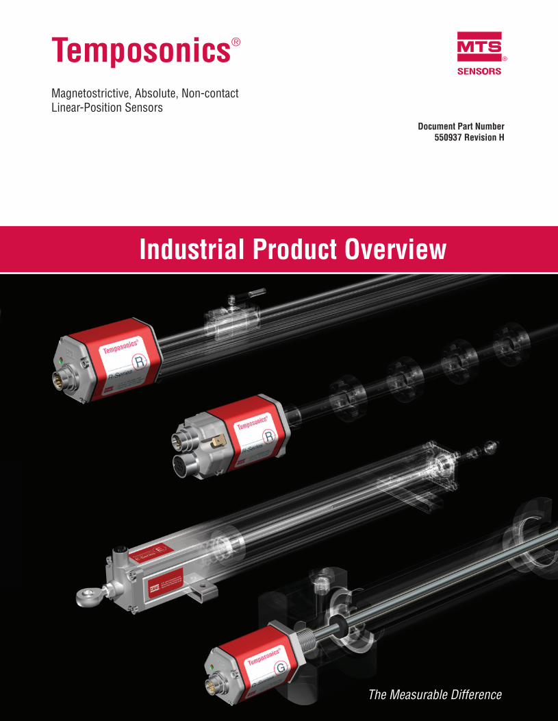
Temposonics®
Magnetostrictive, Absolute, Non-contact Linear-Position Sensors
SENSORS
®
Document Part Number550937 Revision H
Industrial Product Overview
The Measurable Difference
Document Part Number: 550937 Revision H, 02/12
MTS Systems CorporationSensors Division
3001 Sheldon DriveCary, North Carolina,27513, USATel.: +1-800-633-7609Fax: +1-919-677-2343 +1-800-498-4442e-mail: [email protected]://www.mtssensors.com
MTS Sensor TechnologieGmbH & Co. KG
Auf dem Schüffel 9D - 58513 Lüdenscheid, GermanyTel.: +49-2351-9587-0Fax: +49-2351-56491e-mail: [email protected]://www.mtssensor.de
MTS Sensors TechnologyCorporation
737 Aihara-cho, Machida-shiTokyo 194-0211, JapanTel.: +81-42-775-3838Fax: +81-42-775-5516e-mail: [email protected]://www.mtssensor.co.jp
MTS and Temposonics are registered trademarks of MTS Systems Corporation.All other trademarks are the property of their respective owners.
Printed in USA. Copyright © 2012 MTS Systems Corporation. All Rights Reserved in all media.
SENSORS
®
SENSORS
®
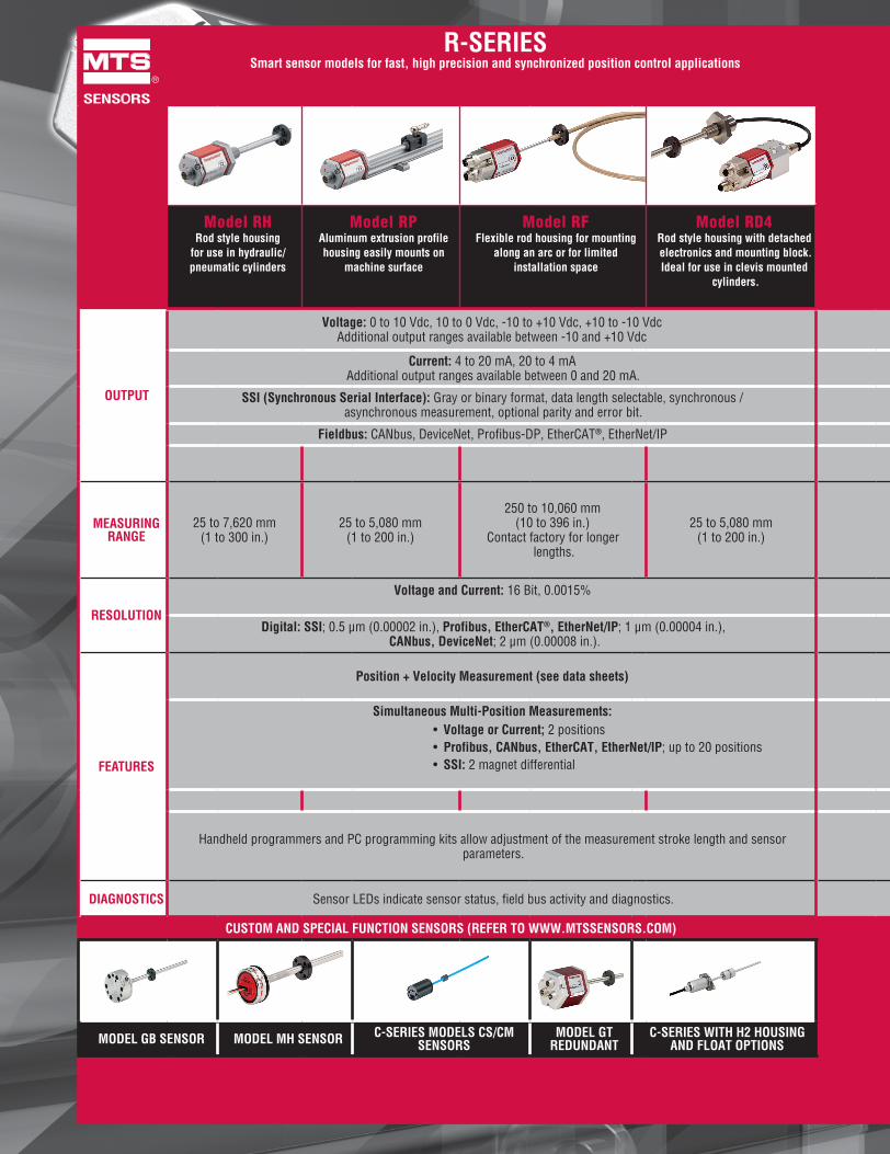
R-SERIESSmart sensor models for fast, high precision and synchronized position control applications
G-SERIESBackward compatibility and upgraded performance for
legacy sensor retrofits
E-SERIESEconomical sensor models for simplistic
position feedback applications
Rod style housing for use in hydraulic/pneumatic cylinders
Aluminum extrusion profile housing easily mounts on
machine surface
Flexible rod housing for mounting along an arc or for limited
installation space
Rod style housing with detached electronics and mounting block. Ideal for use in clevis mounted
cylinders.
Rod or profile style housings
Magnet is secured to the moving machine part and travels over the sensor housing
Compact rod
style housing for use in hydraulic
/ pneumatic cylinders
Aluminum extrusion
profile housing easily mounts on machine surface
Low height profile housing for lower clearance
on machine
Rod-and-cylinder housing provides
versatile mounting options and internal
magnet
OUTPUT
Voltage: 0 to 10 Vdc, 10 to 0 Vdc, -10 to +10 Vdc, +10 to -10 Vdc Additional output ranges available between -10 and +10 Vdc
Voltage: Ranges between -10 and +10 Vdc
Voltage: 0 to 10 Vdc and / or 10 to 0 Vdc
Current: 4 to 20 mA, 20 to 4 mA Additional output ranges available between 0 and 20 mA.
Current: Ranges between 0 and 20 mA
Current: 4 to 20 mA or 20 to 4 mA
SSI (Synchronous Serial Interface): Gray or binary format, data length selectable, synchronous / asynchronous measurement, optional parity and error bit.
Fieldbus: CANbus, DeviceNet, Profibus-DP, EtherCAT®, EtherNet/IP
Digital Pulse: Start / Stop or PWM Digital Pulse: Start / Stop
MEASURINGRANGE
25 to 7,620 mm(1 to 300 in.)
25 to 5,080 mm(1 to 200 in.)
250 to 10,060 mm(10 to 396 in.)
Contact factory for longer lengths.
25 to 5,080 mm(1 to 200 in.)
Voltage and Current: 50 to 2540 mm (2 to 100 in.)
Digital Pulse: 50 to 5080 mm (2 to 200 in.)
Rod style up to 7620 mm (300 in.)
4, 6, 9, 12, 15, 18, 21, 24, 30, 36, 42, 48, 54 and 60 in.
50 to 2500 mm(2 to 100 in.)
For EP Start / Stop only:50 to 3000 mm(2 to 120 in.)
50 to 1500 mm
(2 to 60 in.)
RESOLUTION
Voltage and Current: 16 Bit, 0.0015% Voltage and Current: Infinite(restricted by output ripple)
Voltage and Current: Infinite(restricted by output ripple)
Digital: SSI; 0.5 µm (0.00002 in.), Profibus, EtherCAT®, EtherNet/IP; 1 µm (0.00004 in.), CANbus, DeviceNet; 2 µm (0.00008 in.).
Digital Pulse: 5 µm, dependent on controller Digital Pulse: 5 µm, dependent on controller
FEATURES
Position + Velocity Measurement (see data sheets) Position Measurement Position Measurement
Simultaneous Multi-Position Measurements: • Voltage or Current; 2 positions• Profibus, CANbus, EtherCAT, EtherNet/IP; up to 20 positions• SSI: 2 magnet differential
Simultaneous Multi-Position Measurement
for Start / Stop (controller dependent)
Simultaneous Multi-Position Measurement:• Voltage or current; 2 positions• Start/Stop (controller dependent)
Sensor parameters upload feature for Start/Stop models
Handheld programmers and PC programming kits allow adjustment of the measurement stroke length and sensor parameters.
Change measurement stroke length and output using
handheld programmers and PC programming kits
DIAGNOSTICS Sensor LEDs indicate sensor status, field bus activity and diagnostics. Sensor LEDs indicate status and diagnostics
CUSTOM AND SPECIAL FUNCTION SENSORS (REFER TO WWW.MTSSENSORS.COM) ACCESSORIES
MODEL GB SENSOR MODEL MH SENSOR C-SERIES MODELS CS/CM SENSORS
MODEL GT REDUNDANT
C-SERIES WITH H2 HOUSING AND FLOAT OPTIONS CONNECTORS & CABLES MAGNETS &
FLOATSPROGRAMMING
TOOLSEXPLOSION-PROOF
HOUSING PROTECTIVE HOUSINGS

SENSORS
®
R-SERIESSmart sensor models for fast, high precision and synchronized position control applications
G-SERIESBackward compatibility and upgraded performance for
legacy sensor retrofits
E-SERIESEconomical sensor models for simplistic
position feedback applications
Rod style housing for use in hydraulic/pneumatic cylinders
Aluminum extrusion profile housing easily mounts on
machine surface
Flexible rod housing for mounting along an arc or for limited
installation space
Rod style housing with detached electronics and mounting block. Ideal for use in clevis mounted
cylinders.
Rod or profile style housings
Magnet is secured to the moving machine part and travels over the sensor housing
Compact rod
style housing for use in hydraulic
/ pneumatic cylinders
Aluminum extrusion
profile housing easily mounts on machine surface
Low height profile housing for lower clearance
on machine
Rod-and-cylinder housing provides
versatile mounting options and internal
magnet
OUTPUT
Voltage: 0 to 10 Vdc, 10 to 0 Vdc, -10 to +10 Vdc, +10 to -10 Vdc Additional output ranges available between -10 and +10 Vdc
Voltage: Ranges between -10 and +10 Vdc
Voltage: 0 to 10 Vdc and / or 10 to 0 Vdc
Current: 4 to 20 mA, 20 to 4 mA Additional output ranges available between 0 and 20 mA.
Current: Ranges between 0 and 20 mA
Current: 4 to 20 mA or 20 to 4 mA
SSI (Synchronous Serial Interface): Gray or binary format, data length selectable, synchronous / asynchronous measurement, optional parity and error bit.
Fieldbus: CANbus, DeviceNet, Profibus-DP, EtherCAT®, EtherNet/IP
Digital Pulse: Start / Stop or PWM Digital Pulse: Start / Stop
MEASURINGRANGE
25 to 7,620 mm(1 to 300 in.)
25 to 5,080 mm(1 to 200 in.)
250 to 10,060 mm(10 to 396 in.)
Contact factory for longer lengths.
25 to 5,080 mm(1 to 200 in.)
Voltage and Current: 50 to 2540 mm (2 to 100 in.)
Digital Pulse: 50 to 5080 mm (2 to 200 in.)
Rod style up to 7620 mm (300 in.)
4, 6, 9, 12, 15, 18, 21, 24, 30, 36, 42, 48, 54 and 60 in.
50 to 2500 mm(2 to 100 in.)
For EP Start / Stop only:50 to 3000 mm(2 to 120 in.)
50 to 1500 mm
(2 to 60 in.)
RESOLUTION
Voltage and Current: 16 Bit, 0.0015% Voltage and Current: Infinite(restricted by output ripple)
Voltage and Current: Infinite(restricted by output ripple)
Digital: SSI; 0.5 µm (0.00002 in.), Profibus, EtherCAT®, EtherNet/IP; 1 µm (0.00004 in.), CANbus, DeviceNet; 2 µm (0.00008 in.).
Digital Pulse: 5 µm, dependent on controller Digital Pulse: 5 µm, dependent on controller
FEATURES
Position + Velocity Measurement (see data sheets) Position Measurement Position Measurement
Simultaneous Multi-Position Measurements: • Voltage or Current; 2 positions• Profibus, CANbus, EtherCAT, EtherNet/IP; up to 20 positions• SSI: 2 magnet differential
Simultaneous Multi-Position Measurement
for Start / Stop (controller dependent)
Simultaneous Multi-Position Measurement:• Voltage or current; 2 positions• Start/Stop (controller dependent)
Sensor parameters upload feature for Start/Stop models
Handheld programmers and PC programming kits allow adjustment of the measurement stroke length and sensor parameters.
Change measurement stroke length and output using
handheld programmers and PC programming kits
DIAGNOSTICS Sensor LEDs indicate sensor status, field bus activity and diagnostics. Sensor LEDs indicate status and diagnostics
CUSTOM AND SPECIAL FUNCTION SENSORS (REFER TO WWW.MTSSENSORS.COM) ACCESSORIES
MODEL GB SENSOR MODEL MH SENSOR C-SERIES MODELS CS/CM SENSORS
MODEL GT REDUNDANT
C-SERIES WITH H2 HOUSING AND FLOAT OPTIONS CONNECTORS & CABLES MAGNETS &
FLOATSPROGRAMMING
TOOLSEXPLOSION-PROOF
HOUSING PROTECTIVE HOUSINGS

Temposonics®
Magnetostrictive, Absolute, Non-contact Linear-Position Sensors
SENSORS
®
Document Part Number550937 Revision H
Industrial Product Overview
The Measurable Difference
Document Part Number: 550937 Revision H, 02/12
MTS Systems CorporationSensors Division
3001 Sheldon DriveCary, North Carolina,27513, USATel.: +1-800-633-7609Fax: +1-919-677-2343 +1-800-498-4442e-mail: [email protected]://www.mtssensors.com
MTS Sensor TechnologieGmbH & Co. KG
Auf dem Schüffel 9D - 58513 Lüdenscheid, GermanyTel.: +49-2351-9587-0Fax: +49-2351-56491e-mail: [email protected]://www.mtssensor.de
MTS Sensors TechnologyCorporation
737 Aihara-cho, Machida-shiTokyo 194-0211, JapanTel.: +81-42-775-3838Fax: +81-42-775-5516e-mail: [email protected]://www.mtssensor.co.jp
MTS and Temposonics are registered trademarks of MTS Systems Corporation.All other trademarks are the property of their respective owners.
Printed in USA. Copyright © 2012 MTS Systems Corporation. All Rights Reserved in all media.
SENSORS
®