Embed Size (px)
Citation preview
Level Plus® Liquid-Level Sensors, M-Series Model MG TransmitterProduct Catalog Part No.: 551050, Revision E 02-11MTS Sensors M
odel
MG
Digi
tal
All specifications are subject to change. Contact MTS for specifications and engineering drawings that are critical to your application. Drawings contained in this document are for reference only. Go to http://www.mtssensors.com for the latest support documentation and related media.
FMAPPROVED
17
Level Plus®
Magnetostrictive Liquid-Level Sensors
with Temposonics® Technology
M-Series Model MGTransmitter with Digital Output
Data Sheet
Document Reference Number550784 Revision I
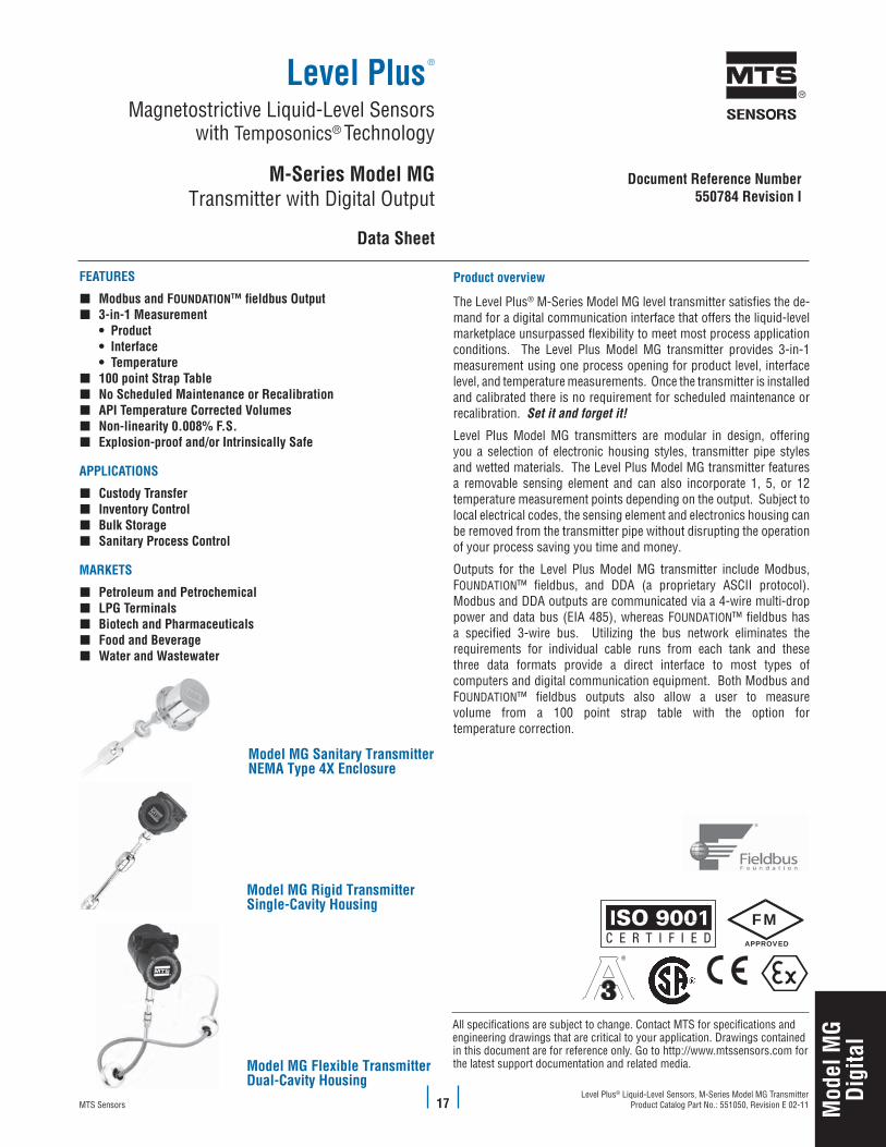
Model MG Rigid TransmitterSingle-Cavity Housing
Model MG Sanitary TransmitterNEMA Type 4X Enclosure
Model MG Flexible TransmitterDual-Cavity Housing
FEATuRES
Modbus and F � OuNDATION™ fieldbus Output3-in-1 Measurement �
• Product • Interface • Temperature
100 point Strap Table �No Scheduled Maintenance or Recalibration �APITemperatureCorrectedVolumes �Non-linearity 0.008% F.S. �Explosion-proof and/or Intrinsically Safe �
APPLICATIONS
Custody Transfer �Inventory Control �Bulk Storage �SanitaryProcessControl �
MARKETS
PetroleumandPetrochemical �LPGTerminals �BiotechandPharmaceuticals �Food and Beverage �Water and Wastewater �
Productoverview
The Level Plus® M-Series Model MG level transmitter satisfies the de-mand for a digital communication interface that offers the liquid-level marketplace unsurpassed flexibility to meet most process application conditions. The Level Plus Model MG transmitter provides 3-in-1 measurement using one process opening for product level, interface level, and temperature measurements. Once the transmitter is installed and calibrated there is no requirement for scheduled maintenance or recalibration. Set it and forget it!
Level Plus Model MG transmitters are modular in design, offering you a selection of electronic housing styles, transmitter pipe styles and wetted materials. The Level Plus Model MG transmitter features a removable sensing element and can also incorporate 1, 5, or 12 temperature measurement points depending on the output. Subject to local electrical codes, the sensing element and electronics housing can be removed from the transmitter pipe without disrupting the operation of your process saving you time and money.
Outputs for the Level Plus Model MG transmitter include Modbus, FOUNDATION™ fieldbus, and DDA (a proprietary ASCII protocol). Modbus and DDA outputs are communicated via a 4-wire multi-drop power and data bus (EIA 485), whereas FOUNDATION™ fieldbus has a specified 3-wire bus. Utilizing the bus network eliminates the requirements for individual cable runs from each tank and these three data formats provide a direct interface to most types of computers and digital communication equipment. Both Modbus and FOUNDATION™ fieldbus outputs also allow a user to measure volume from a 100 point strap table with the option for temperature correction.

Mod
el M
GDi
gita
l
Level Plus® Liquid-Level Sensors, Model MG TransmitterProduct Catalog Part No.: 551050, Revision E 02-11 MTS Sensors 18
Parameters Specifications
LEVELOUTPUT
Measured variable: Product level and interface level
Output signal /Protocol:
Modbus RTU, DDA or FOUNDATION™ fieldbus
Order length: Flexible hose:(FM, CSA, ATEX IIA):3048 mm (120 in.) to 22000 mm (866 in.) ∆ §(ATEX IIB):3048 mm (120 in.) to 13500 mm (531.5 in.) ∆ §Rigid pipe: 508 mm (20 in.) to 7620 mm (300 in.) ∆ §Sanitary pipe: 508 mm (20 in.) to 7620 mm (300 in.) ∆ §
∆ Contact factory for longer lengths.§ Order length equals the measurement range plus
the inactive zone.
Non-linearity: 0.008% F.S. or 0.794 mm (1/32 in.)*
* Whichever is greater
Hysteresis: 0.002% F.S. or 0.397 mm (1/64 in.)*(any direction) * Whichever is greater
Resolution: 0.025 mm (0.001 in.)
Calculated variables:
GOVPGOVIGOVTGOVUNSVP
TEmPErATUrEOUTPUT
Measured variable:
Average and multi-point temperatures Up to 12 Modbus ∞Up to 5, DDA and FOUNDATION™ fieldbus
∞ Minimum length of 2032 mm (80 in.) for 12 temperature positions.
Temperature accuracy: ±0.28 ºC (±0.5 ºF)
ELECTrONICS
Input voltage: Modbus and DDA:10.5 to 30.1 Vdc28 Vdc maximum for I.S. ATEX approval FOuNDATION™ fieldbus: 9 to 32 Vdc bus powered
Fail safe: High, full scale
Reverse polarity protection: Series diode
Parameters Specifications
Lightning/Transient protection:
Stage 1: Line-to-ground surge suppression; IEC 61000-4-5Stage 2: Line-to-line and line-to-ground transient suppressors; IEC 61000-4-4
CALIBrATION
Zero adjust range: Anywhere within the active length
Span adjust range: Full scale to 152 mm (6 in.) from zero
ENVIrONmENTAL
Enclosure rating: NEMA Type 4X
Humidity: 0 to 100% relative humidity, non-condensing
Operating temperatures:
Electronics: -40 °C (-40 °F) to 71 °C (160 ºF) Sensing element: -40 °C (-40 °F) to 125 °C (257 °F) ◊Temperature element: -40 °C (-40 °F) to 105 °C (221 °F)
◊ Contact factory for specific temperature ranges.
Vesselpressure: Dependent on float pressure, contact factory for more information
Materials: Wetted parts: 316L stainless steel †Non-wetted parts: 316L stainless steel, Epoxy coated aluminum
† Contact factory for alternative materials.
fIELdINSTALLATION
Housing dimensions:
Single cavity:127 mm (5 in.) by 123 mm (4.85 in.)121 mm (4.75 in.) O.D.Dual cavity:127 mm (5 in.) by 177 mm (6.95 in.)121 mm (4.75 in.) O.D.NEMA Type 4X:81 mm (3.2 in.) by 123 mm (4.85 in.) O.D.
Mounting: Rigid pipe: ¾ in. Adjustable MNPT fitting, Flange and Tri-Clamp® Mounts
Flexible hose: 1 in. Adjustable MNPT fitting, Flange mount
Wiring: Modbus and DDA:4-wire connections plus earth ground.Daniel Woodhead 6-pin male connector.Integral cable with pigtails.
FOuNDATION™ fieldbus: Type A fieldbus cable
ELECTrICALCONNECTIONS
Single and Dual Cavity:
¾ in. FNTP conduit opening, M20 for ATEX version
NEMA Type 4X: ½ in. FNTP conduit opening
Productspecifications
LevelPlus® modelmGProductSpecifications

Mod
el M
GDi
gita
l
Level Plus® Liquid-Level Sensors, Model MG TransmitterProduct Catalog Part No.: 551050, Revision E 02-11 MTS Sensors 20
Installation guideline, rigid pipeMTS offers the Level Plus Model MG transmitter configured with a rigid pipe constructed of 316L stainless steel (see illustration below). The rigid pipe configuration can be ordered in lengths from 508 mm (20 in.) to 7620 mm (300 in.). The Model MG transmitter is typically ordered with a ¾ in. MNPT Adjustable fitting which allows the transmitter order length to be adjusted (within a few inches) if the tank height and order length are not exactly equal.
The ‘Measuring range’ of the Model MG transmitter is equal to the ‘Order length’ minus the ‘Inactive zone’ of 74 mm (2.9 in.). The transmitter can be ordered with a single product float or can include the optional interface float (Refer to the Level Plus Accessories Catalog, document no. 551103 for optional float selections). If required, temperature measurement is also an option.
A stop collar is included which is designed to keep the float out of the inactive zone. The placement of the stop collar is dependent on the float and placement of the magnet. If your application requires measuring to the bottom of your vessel, ask MTS about our ‘low liftoff’ float option which can measure less than 25 mm (1 in.) of liquid.
165 mm(6.5 in.)
Weldedflange
See Transmitter Inactive Zone reference below
FNPT
TrANSmITTErINACTIVEZONErEfErENCE
Material OrderLength1219mm(<48in.) OrderLength1220mm(>48in.)
316L SS, Hastelloy C 74 mm (2.9 in.) 74 mm (2.9 in.)
Teflon 114 mm (4.5 in.). 132 mm (5.2 in.)
LevelPlus® Model MG Installation GuidelinerigidPipeApplications

Mod
el M
GDi
gita
l
Level Plus® Liquid-Level Sensors, Model MG TransmitterProduct Catalog Part No.: 551050, Revision E 02-11MTS Sensors 21
LevelPlus® Model MG Installation GuidelineFlexible Hose Applications
Installation guideline, flexible hoseMTS offers the Level Plus Model MG transmitter configured with a Flexible hose constructed of 316L stainless steel (see illustration below). The flexible hose configuration can be ordered in lengths from 3048 mm (120 in.) to 22,000 mm (866 in.). The Level Plus Model MG transmit-ter for flexible hose applications is typically ordered with a 1 in. adjustable MNPT fitting. This fitting allows the transmitter to be adjusted (within a few inches) if the order length is not exact.
The Model MG transmitter ‘Measuring range’ is equal to the ‘Order length’ minus the ‘Inactive zone’ (refer to the Transmitter Inactive Zone Reference table below). The ‘Order length’ should equal the ‘Tank height’ minus 51 mm (2.0 in.). The transmitter can be ordered with a single product float or can include the optional interface float (Refer to the Level Plus Accessories Catalog, document no. 551103 for optional float selections). If required, temperature measurement is also an option.
A stop collar is also included which is designed to keep the float out of the inactive zone. The placement of the stop collar is dependent on the float and placement of the magnet. If your application requires measuring to the bottom of your vessel, ask MTS about our ‘low liftoff’ ’float option which can measure less than 25 mm (1 in.) of liquid.
TrANSmITTErINACTIVEZONErEfErENCE
Length Inactive Zone
< 7.6 m (25 ft.) 76 mm (3 in.)
< 12.2 m (40 ft.) 97 mm (3.8 in.)
< 22 m (72.2 ft.) 120 mm (4.7 in.)
(Customer supplied)
Stainless-steel
Riser
127 mm(5 in.)
210 mm(8.25 in.)
Stop Collar
305 mm (12 in.)Minimum height
Total InactiveZone
Transmitter InactiveZone (See Table)
76 mm(3 in.)
2 in.(typ.)
127 mm(5 in.)
Bottom-FixingHook
Bottom-Fixing Weight Bottom-Fixing Magnet
Tank height
Order length3048 mm (120 in.) to22,000 mm (866 in.)
Measuring range
305 mm(12 in.)
Weldedflange
FNPT

Mod
el M
GDi
gita
l
Level Plus® Liquid-Level Sensors, Model MG TransmitterProduct Catalog Part No.: 551050, Revision E 02-11 MTS Sensors 22
LevelPlus® Model MG Installation GuidelineSanitaryPipeApplications
Installation guideline, sanitary pipeMTS offers the Level Plus Model MG transmitter configured with a Sanitary pipe constructed of 316L stainless steel (see illustration below). The sanitary pipe configuration can be ordered in lengths from 508 mm (20 in.) to 7620 mm (300 in.). The 316L sanitary pipe comes standard with a Ra 25 μm (0.625 μm) finish, however an electropolish option is also available with a Ra 15 μm (0.375 μm) finish. The standard process fitting is a welded Tri-Clamp® cap. Because the Tri-Clamp cap is welded, it is imperative that the correct order length is provided. The order length should be equal to the height from the bottom of the tank to the top of the process connection on the tank.
The Model MG transmitter ‘Measuring range’ is equal to the ‘Order length’ minus the ‘Inactive zone’. The inactive zone measurement is dependent on the end plug style chosen (shown in the table below). The standard sanitary float magnet is offset to ensure the magnet does not enter the inactive zone despite the end plug. The transmitter can be ordered with a single product float or can include the optional interface float (Refer to the Level Plus Accessories Catalog, document no. 551103 for optional float selections). If required, temperature measurement is also an option.
Tri-Clamp® Cap sizeSanitary
Tri-Clamp® Cap
SanitaryTri-Clamp® Fitting
Inactive Zone(See Important Note below)
½ in. FNPT
Inactive zone81 mm (3.2 in.)from tip (typical)
Inactive zone74 mm (2.9 in.)from tip (typical)
Inactive zone81 mm (3.2 in.)from tip (typical)
Inactive zone74 mm (2.9 in.)from tip (typical)
TBSanitary ◊
DPDrain-in-place
with end plug ◊
CPClean-in-place
DNDrain-in-place
no through hole
◊ End plug style comes with permanently mounted floats. These floats cannot be removed from the pipe.