Embed Size (px)
Citation preview
@LEVEL"ADZIIZZ
TECHNICAL REPORT ARBRL-TR-02271
II
IMPACT DYNAMICS: THEORY AND EXPERIMENT
J. A. Zukas
October 1980 DTIC'SELECTE
B '
US ARMY ARMAMENT RESEARCH AND DEVELOPMENT COMMAND
BALLISTIC RESEARCH LABORATORYABERDEEN PROVING GROUND, MARYLAND
Approved for-public release; distribution unlimited.
80 12 18 039

Destroy this report when it is no longer needed.Do not return it to the originator.
Secondary distribution of this report by originatingor sponsoring activity is prohibited.
Additional copies of this report may be obtainedfrom the National Technical Infomation Service,U.S. Department of Comuerce, Springfield, Virginia
j
221S1.-
The findinis in this report are not to be construed asan official Department of the Army position, unless
so designated by other-authorized documents.
doe not const~itute indorsewnt of ow •'ammi p.-qdud'. "

UNCLASSIFIEDSECURITY CLASSIFICATION OF THIS PAGE (lMlhn Data Entered)
REPORT DOCUMENTATION PAGE READ INSTRUCTIONSBEFO.E COMPLETING FORM
1. REPORT NUMBER 2. GOVT ACCESSION NO. 3. RECIPIEt.TS CATALOG NUMBER
TECHNICAL REPORT ARBRL-TR-02271 ____ 90 -Y-_QOD--4. TITLE (,rod Subtitle) S. TYPE OF REPORT & PERIOD COVERED
IMPACT DYNAMICS: THEORY AND EXPERIMENT Final6. PERFORMING ORG. REPORT NUMBER
7. AUTHOR(a) 8. CONTRACT OR GRANT NUMBER(e)
J. A. Zukas
9. PERFORMING ORGANIZATION NAME AND ADDRESS 10. PROGRAM ELEMENT. PROJECT. TASKAREA & WORK UNIT NUMBERS
U.S. Army Ballistic Research Laboratory(ATTN: DRDAR-BLT)Aberdeen Proving Ground, MD 21005 ILI62618AH80
II. CONTROLLING OFFICE NAME AND ADDRESS 12. REPORT DATEU.S. Army Armament Research and Development Command OCTOBER 1980U.S. Army Ballistic Research Laboratory 13. NUMBEROF PAGES(ATTN: DRDAR-BL) 67 1R GAbevdecn Proving Groiind MI) 21171r 67M14. MONITORING AGENCY NAME & ADDRESS(If different from Controlling Office) 15. SECURITY CLASS. (of thi, report)
UNCLASSIFIED15o. DECLASSIFICATION/DOWNGRADING
SCHEDULE
16. DISTRIBUTION STATEMENT (of this Report)
V*.Approved for public release, distribution unlimited.
17. DISTRIBUTION STATEMENT (of the abstract entered In Block 20, If different from Report)
18. SUPPLEMENTARY NOTES
'Iii
19. KEY WORDS (Continue ., reveree side If neceseay and identify by block number)
Impact Dynamics Wave PropagationTerminal Ballistics Impulse LoadingDynamic Fracture Structural DynamicsPenetration & Perforation .
20. ABSTRACT (Continue on reverse side It necessary end Identify by block ntusber) 2h.b)
A review is presented of the state of the art in the analysis of materialsand structures subjected to intense impulsive loading. Emphasis is placed on th(penetration and perforation of solids and current developmt its in three-dimensioz-al finite element and finite difference simulation of impact phenomena. Theneed for adequate characterization uf material response and failure at highstrain rates is emphasized and current capabilities highlighted. An assessmentis made of anticipated developments and advances in high speed computers, high
(continued)DD• FORM 1.1 O NVO I NSLT
DO , JA 147 -. ON oFT NOVT31SObSOLETE UNCLASSIFIED
SECURITY CLASSIFICATION OF THIS PAGE (WNen Dole Enteored)

UINCLASSI FIEDSECURITY CLASSIFICATION OF THIS PAGECOIWm Date Daftre'
strain rate materials characterization, and in numerical simulation techniqueswhich will contribute to improved design and reduced vulnerability of materialsand structures to impact loading.
~ 1
!I-4
P,,
IINCI.ASS I F IIlSECURITY CLASSIFICATION OF THIS PAGI`(?•t., , .- ..r..
ld • " '•-' •;..,° • " .... " .. . -'- , • c4 ...'.S9 ..- -,, ... . ... ,. - .... .. .. . .. .•. .... . .
TABLE OF CONTENTSPage
LIST OF ILLUSTRATIONS ................ . .
I. INTRODUCTION ............. ...................... .
A. General ............ ..................... 7
B. Penetration & Perforation of Solids..... . 9
II. NUMERICAL SIMULATION OF IMPACT PHENOMENA .... ........ 17
A. General Considerations ..... ............. ... 17
B. Discretization Methods .... ............. .. 21
C. Mesh Descriptions ...... ................ .. 23D. Temporal Integration Schemes .............. .. 25
E. Computer Resource Requirements ............ .. 28
F. Material Model ...... ................. ... 29
III. CURRENT CODE CAPABILITIES ...... ................ .. 32
A. Two-Dimensional Lagrangian Codes .... ........ 32
B. Two-Dimensional Eulerian Codes ........... ... 33
C. Three-Dimensional Codes ...... ............. 35
IV. EXAMPLES ............... ........................ 37
A. Sphere Ricochet ...... ................. ... 37
B. Yawed Rod Impact ...... ................ ... 40
C. Hydrodynamic Ram ...... ................ ... 42
V. COMPUTATIONAL FAILURE MODELS ..... .............. .. 43
VI. PROGNOSIS .............. ........................ 48
REFERENCES ............... ....................... 53DISTRIBUTION LIST ........ .................... .. 61
39-'

Effi~UDPAGI Kha-ho? ]IMUM
LIST OF ILLUSTRATIONS
Figure Page
1. Failure modes in impacted plates ...... ............ 11
2. Experimental test set-up of x-ray instrumentationfor obtaining peretration data for projectiles. 13
3. Computational process for impact simulation .... ...... 19
4. Lagrangian computational grid .... ............. .... 24
S. Eulerian computational grid ..... .............. ... 26
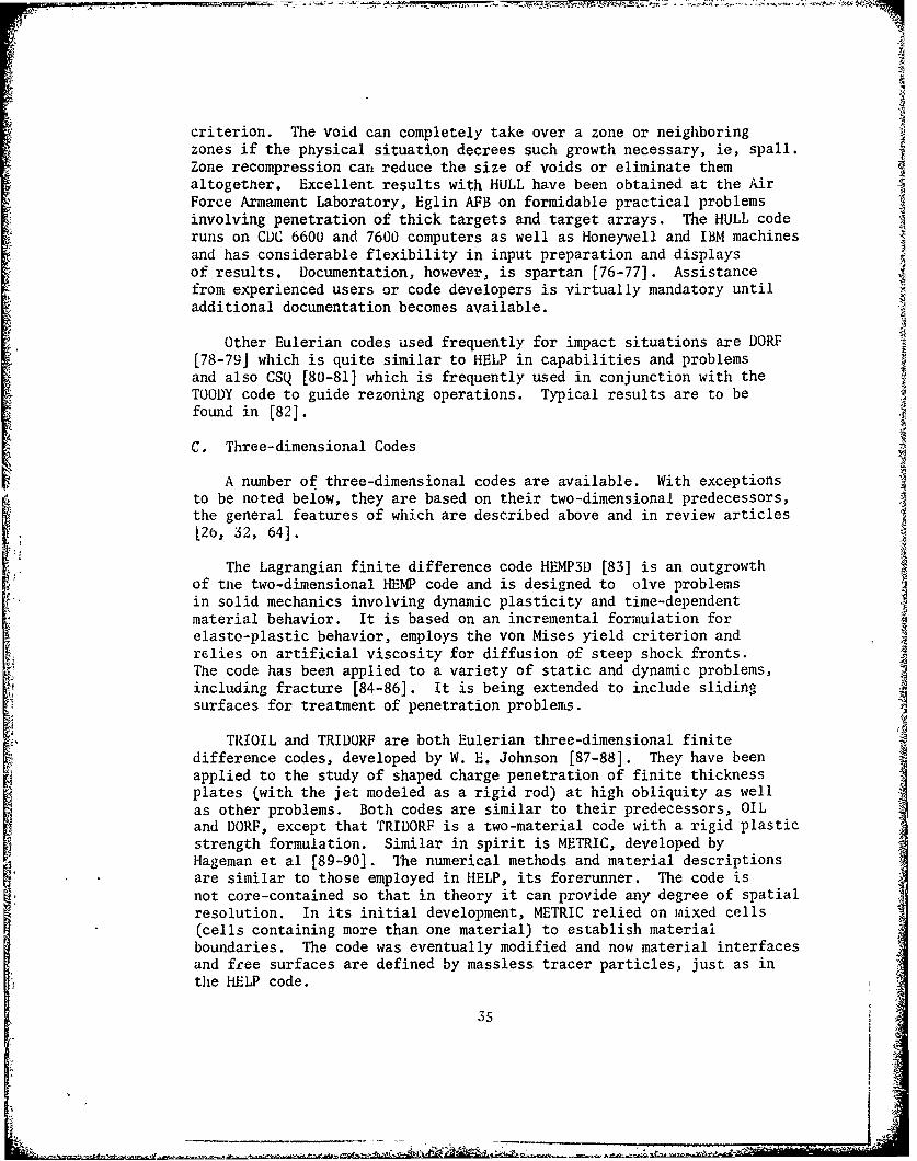
6. Deformation profiles for oblique impact of steelsphere into aluminum target at various times ..... .. 3 33
7. Velocity histories for oblique impact of steel sphereinto aluminum target ........ ................. 39
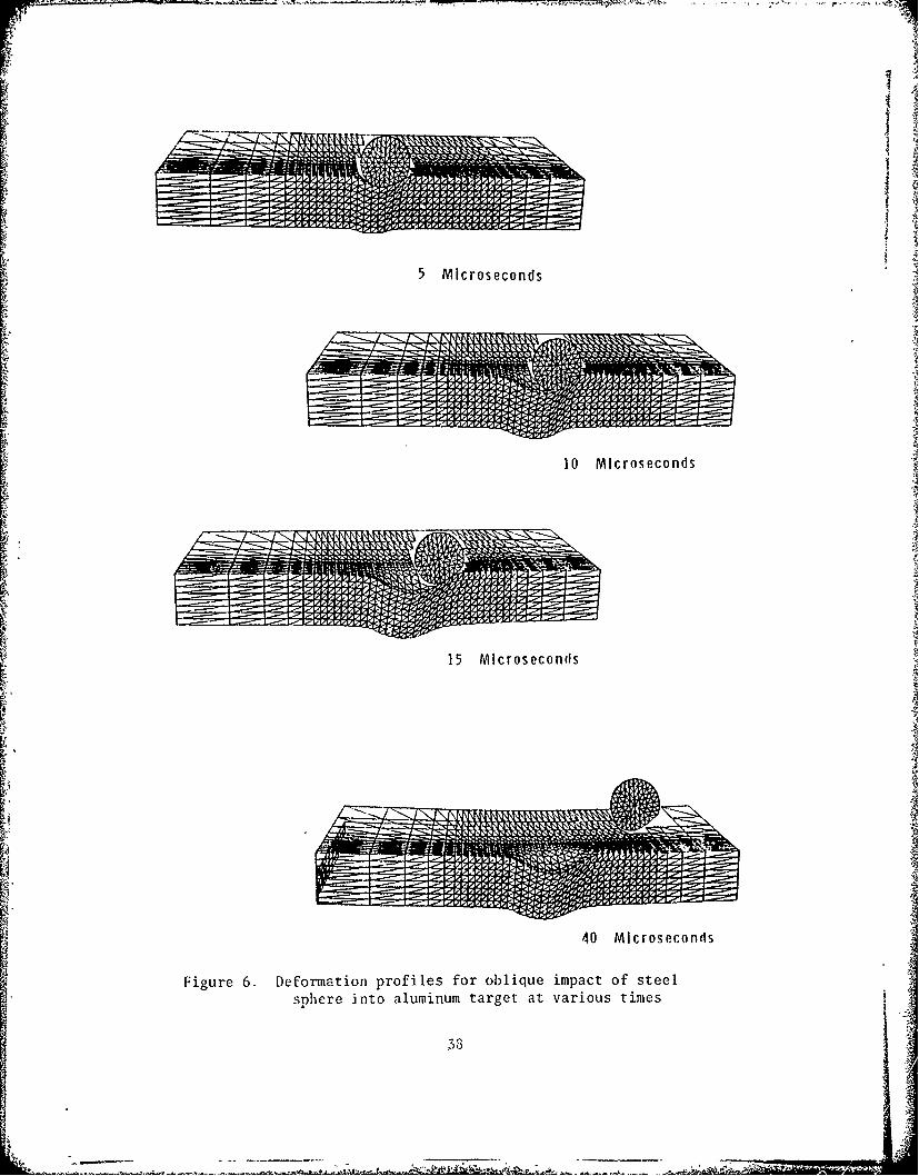
8. Rod deformation at various times............ ..... 41
9. Deformations and pressures in fuel tank simulatorat 40 and 180 pm ...... ................... ... 44
I.
Accession For
NTIS GRA&IDTIC TABUnannouncedJustificatio
By-Distribution/--
SAvailability Codes_":iAvail and/or
SDist ISpecial
4FIEitOIM PAGE RLAWKI4OT 7IUMEI
I. INTRODUCTION -
A. General
Situations involving impact--the collision of two or more solidbodies-- are currently receiving widespread attention. Traditionally,the prime interest in this area has been for military applications.However, advances in technology have placed such severe demands onmaterials behavior under short-term loading that current interest inthe response of materials and structures to intense impulsive loadingcenters on such problems as
- transportation safety of hazardous materials
- vehicle crashworthiness
- safety of nuclear reactor structures subjected to impact bytornado-borne debris and aircraft collisions
- the vulnerability of military vehicles, structures, and aircraftto impact and explosive loading
- design of lightweight armor systems
- erosion and fracture of solids due to liquid and solid particleimpacts
- protection of spacecraft from nmteoroid impact
- explosive forming and welding of metals.
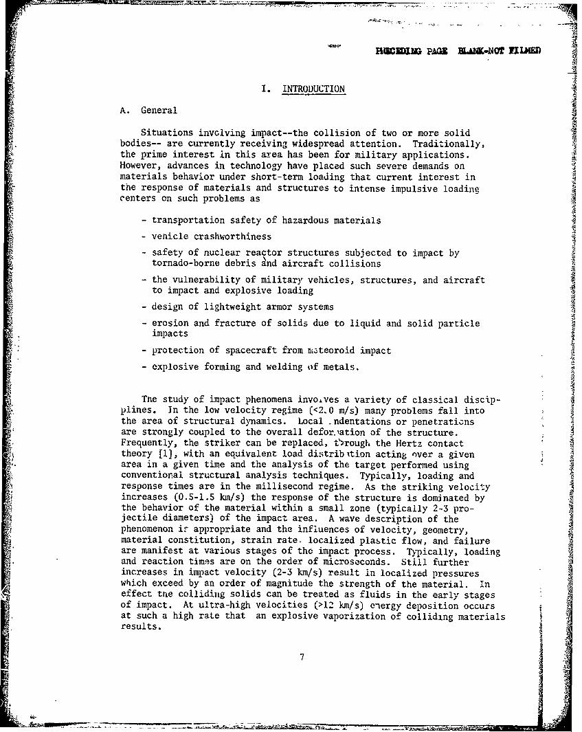
The study of impact phenomena involves a variety of classical discip-plines. In the low velocity regime (<2.0 m/s) many problems fall intothe area of structural dynamics. Local .ndentations or penetraticnsare strongly coupled to the overall defor.lation of the structure.Frequently, the striker can be replaced, t.ýrough the Hertz contacttheory [1], with an equivalent load distribition acting over a givenarea in a given time and the analysis of the target performed using 4conventional structural analysis techniques. Typically, loading andresponse times are in the millisecond regime. As the striking velocityincreases (0.5-1.5 km/s) the response of the structure is dominated bythe behavior of the material within a small zone (typically 2-3 pro-jectile diameters) of the impact area. A wave description of the Iphenomenon iF appropriate and the influences of velocity, geometry,material constitution, strain rate. localized plastic flow, and failureare manifest at various stages of the impact process. Typically, loadingand reaction times are on the order of microseconds. Still furtherincreases in impact velocity (2-3 km/s) result in localized pressureswhich exceed by an order of magnitude the strength of the material. Ineffect tne colliding solids can be treated as fluids in the early stagesof impact. At ultra-high velocities (>12 km/s) energy deposition occursat such a high rate that an explosive vaporization of colliding materialsresults.1* ~7

Impact phenomena can be characterized in a number of ways:according to the impact angle, the geometric and material c&'aracteristicsof the target or projectile, or striking velocity. The latter approachis adopted in Table 1 which provides a short classification of impactprocesses as a function of striking velocity, V s, and strain rate, •.The impact velocity ranges should be considered only as reference points.In fact, these transitions are extraordinarily flexible since deformationprocesses under impact loading depend on a long series of parameters inaddition to impact velocity.
Table 1. Impact response of Materials
VS EFFECT METHOD OF LOADING
> 12V kms-E EXPLOSIVE IMPACT-10 8 -COLLIDING SOLIDSVAPORIZED
3 3-12 k ms-1 HYDRODYNAMIC- EXPLOSIVE ACCELERATIONMATERIAL COMPRESSI-
106 BILITY NOT IGNORABLE
I1-3 kms-l FLUID BEHAVIOR IN POWDER GUNS,GAS GUNSMATERIALS,* PRESSURES
APPROACH 6R EXCEEDMATERIAL STRENGTH;DENSITY /A DOMINANT'PARAMETER
104 - 500-1000ms-1 VISCOUS-MATERIAL POWDER GUNSSTRENGTH STILLSIGNIFICANT
10 2 50- 500 ms- PRIMARILY PLASTIC MECHANICAL DEVICES,1 5COMPRESSED AIR GUN
100 - < 50ms" S PRIMARILY ELASTIC MECHANICAL DEVICES,SOME LOCAL COMPRESSED AIR GUNPLASTICITY

A comrlete treatment of the impact r, sponse of materials and struc-tures would demand that account be t.k,,& of the geometry of interactingbodies, elastic-plastic and shock wpie propagation, hydrodynamic flow,finite strains and deflections, stcain rate effects, work hardening,thermal and frictional effects, and the initiation and propagation offailure in the colliding materials. An analytical approach would notonly be formiHable but would also require a degree of material charac-terizav"ron under high st.rain rate loading that could not be attainedin pr-.tice. Hence, much of the work in this field has been experimen-tal ii, iature.. Existing analytical models generally incorporate a highdegree of empiricism and focus on one or two aspects of the impact res-ponse of solids. Extensive reviews of existing models have appearedrecently [2,3] . This paper focuses on numerical techniques for highvelocity impact (0.5-2 km/s) simulations, their current capabilitiesand limitations. Some remarks about anticipated developments are alsomade. For the sake of completeness, the basic mechanisms involved inthe penetration and pcrforation of solids are stated. Emphasis isoAaced on solid-solid impacts where both loading and response times area, the sub-millisL..ond regime. No account is given of the impacti:-s..?,e of composite materials. Problems dealing with blast loading ors!iajqr :harge a~tack of structures are beyond the scope of this paper.
Penetration and Perforation of Solids
Penetration may be defined as the entrance of a projectile into atarget without completing its passage thrcugh the body [2]. Thisinvolves either embedment or rebound of the striker and the formation of- crater in the target. Perforation, on the other hand, implies thecomplete piercing of a target by the projectile. Such processes occurin a time frame of several to sever.l hundred microseconds. Targetsand projectiles are deformed severely during such encounters.
Consider the events which occur in projectile and target duringimpact. For purposes of this discussion, consider the projectile to bein the form of a long rod, generally cylindrical in shape, with conical,ogival, hemispherical or flat nose. When such a projectile strikes atarget, strong compressive waves propagate into both bodies. If theimpact velocity is sufficiently high, relief waves will propagate"inward from the lateral free surfaces of the rod and cross at the center-line, creating a region with high tensile stress. This tensile regioncan cause fracture in sufficiently brittle materials such as high strengthsteels. This effect will be enhanced if centerline porosity or otherimperfections exist in the projectile material. For normal impacts,the state of stress is clearly two-dimensional. For oblique incidence,there is the additional complication of bending stresses due to theasymmetry of the loading. Under the proper combinations of projectilegeometry, material charazteristics and impact velocity, the combinedbending and tensile stresses can lead to projectile failure and ricochet.f 9

The initial compression wave in the target is followed quickly bya release wave. When the initial compressive wave reaches a freeboundary in the target, an additional release wave is generated. Jfthe combination of load intensity (tensile) and duration exceeds acritical value for the target material, failure will be initiated.
Targets are best classified following the definitions in [2]. Atarget is said to be:
a. semi-infinite if there is no influence of the distal boundaryon the penetration process
b. thick if there is influence of the distal boundary only aftersubstantial travel of the projectile into the targets
c. intermediate if the rear surface exerts considerable influence
on the deformation prucess during nearly all of the penetrator motion
d. thin if stress and deformation gradients throughout itsthickness do not exist.
Impacted materials may fail in a variety of ways, the actualmechanism depending on such variables as material properties, impactvelocity, projectile shape, method of target support, and relativedimensions of projectile and target. Figure 1, adapted from [ 2,4] ,
shows some of the dominant modes for thin and intermediate thicknesstargets. Spalling, tensile failure due to the reflection of the initialcompressive wave from the rear surface of a finite thickness plate,is a commonplace occurrence under explosive and intense impact loads,especially for materials stronger in compression than in tension.Scabbing is similar in appearance, but here fracture is produced bylarge deformations and its surface is determined by local inhomogeneitiesand anisotropies. Fracture due to an initial stress wave exceeding amaterial's ultimate strength can occur in weak, low-density targetswhile radial cracking is common in materials such as ceramics wherethe tensile strength is considerably lower than the compressive strength.
Pluggir' failure has been studied extensively, both analytically andexperimentally. Impact by a blunt or hemispherically-nosed striker ona finite thickness target at a velocity close to the ballistic limit(the minimum velocity required for perforation) results in the formationof a nearly cylindrical slug of approximately the same diameter as thestriker which is set in motion by the projectile. The mechanism forplug formation has been termed "adiabatic shear banding" because of thehard white bands with sharp boundaries observed by etching sections ofplates after plugging failure [5]. The generally accepted mechanism
leading to plugging failure envisions occurrence of a plastic shearinstability at tne site of a stress concentration in an othewiseuniformly straining solid. The work of plastic deformation is convertedalmost entirely into heat which, because of the high deformation rates,is unable to propagate a significant distance away from the plastic
10

11
Ig
BRITTLE FRACTURE DUCTILE HOLE GROWlH1
RADIAL FRACTURE PLUGGING
FRAGMENTATION PETALING
Figure 1. Failure modes in impacted plates
i11
4i ll-,

zone. As a result, the temperature in the zone rises, encouraging
additional local plastic flow and concentrating the local plasticstrain still further. The process continues and results in thepropagation of a narrow band of intense plastic strain through thematerial along planes of maximum shear stress or minimum strength untilunloading occurs or the material fractures. For striking velocities
.exceeding the minimum perforation velocity by more than 5-10%, multiplefragments rather than an intact plug will result. Plugging failureis quite sensitive to the impact angle and nose shape of the projectile.
Petalling is produced by high radial and circumferential tensilestresses after passage of the initial stress wave. The high stressfields occur near the tip of the projectile. Bending moments createdby the forward motion of the plate material pushed by the striker causethe characteristic deformation pattern. It is most freqeuently observedin thin plates struck by ogival or conical bullets at relatively lowimpact velocities or by blunt projectiles near the ballistic limit.Petalling is accompanied by large plastic flows and permanent flexure.Eventually, the tensile strength of the plate material is reached and astar-shaped crack develops around the tip of the projectile. Thesectors so formed are then pushed back by the continuing motion of theprojectile forming petals.
For thick targets impacted by malleable materials at velocitiesexceeding 1 km/s, there is a hydrodynamic erosion and inversion of thepenetrator material against the receding face of the penetrationchannel in the target. The target material is forced aside much asthough a punch were being pushed into it, although the channel is muchbigger than the penetrator diameter.
A combination of ductile failure and spalling seems to becharacteristic for the failure of thick plates of low or medium hardness.
Material failure under impact loading is a most complex process.Even though one of the failure models depicted in Figure 1 may dominate,a second or third mode frequently accompanies the principal failuremode to a lesser extent.
In view of the complexity of penetration processes, it is notsurprising that the bulk of the work in this area is experimental innature. Terminal ballistic test techniques, aside from routine proof Jtests, vary mainly in the degree of instrumentation provided and hencethe amount of data retrieved.
The most common type of ballistic test is designed to obtain Iinformation about
a. the velocity and trajectory of the projectile prior to impact
b. changes in configuration of projectile and target due to impactc. masses, velocities, and trajectories of fragments generated
by the impact process.
12
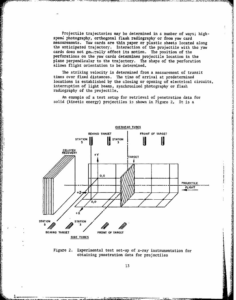
Projectile trajectories may be determined in a number of ways; high-speed photography, orthogonal flash radiography or from yaw cardmeasurements. Yaw cards are thin paper or plastic sheets located alongthe anticipated trajectory. Interaction of the projectile with the yawcards does not gei,•rally affect its motion. The position of theperforations on the yaw cards determines projectile location in theplane perpendicular to the trajectory. The shape of the perforationallows flight orientation to be determined.
S~The striking velocity is determined from a measurement of transit
times over fixed distances. The time of arrival at predeterminedlocations is established by the closing or opening of electrical circuits,interruption of light beams, synchronized photography or flashradiography of the projectile.
(oAn example of a test setup for retrieval of penetration data forS~solid (kinetic energy) projectiles is shown in Figure 2. It is a
OVERHEAD TUBES
BEHIND TARGET FRONT OF TARGET
STATION I STATIONNII5II Ij UN
CELOTEX
RECOVERY +E
•. +y ARGET
0,0 N!
PROJECTILE
-- ---- -- FLIGHT
STATION /STATION
"BEHIND TARGET FRONT OF TARGET
SIDE TUBES
Figure 2. Experimental test set-up of x-ray instrumentation forobtaining penetration data for projectiles
13
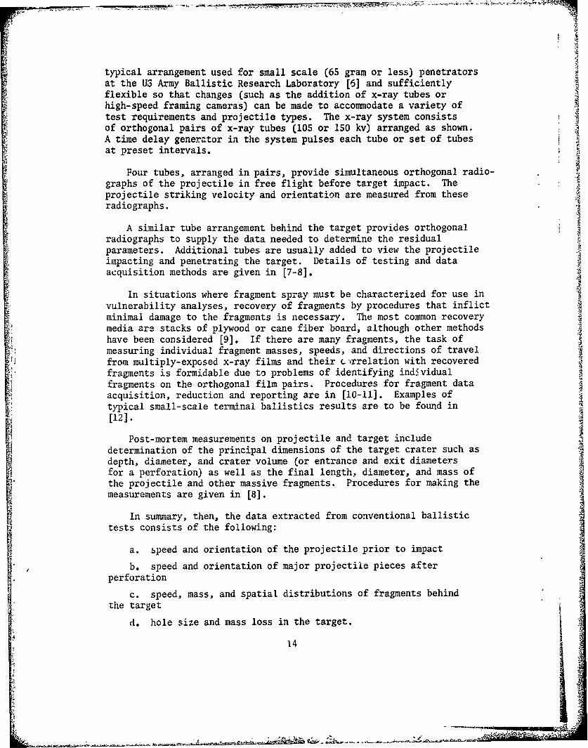
typical arrangement used for small scale (65 gram or less) penetratorsat the US Army Ballistic Research Laboratory [6] and sufficientlyflexible so that changes (such as the addition of x-ray tubes orhigh-speed framing cameras) can be made to accommodate a variety oftest requirements and projectile types. The x-ray system consistsof orthogonal pairs of x-ray tubes (105 or 150 kv) arranged as shown.A time delay generator in the system pulses each tube or set of tubesat preset intervals.
Four tubes, arranged in pairs, provide simultaneous orthogonal radio-graphs of the projectile in free flight before target impact. Theprojectile striking velocity and orientation are measured from theseradiographs.
A similar tube arrangement behind the target provides orthogonalradiographs to supply the data needed to determine the residualparameters. Additional tubes are usually added to view the projectileimpacting and penetrating the target. Details of testing and dataacquisition methods are given in [7-8].
In situations where fragment spray must be characterized for use invulnerability analyses, recovery of fragments by procedures that inflictminimal damage to the fragments is necessary. The most common recoverymedia are stacks of plywood or cane fiber board, although other methodshave been considered [9]. If there are many fragments, the task ofmeasuring individual fragment masses, speeds, and directions of travelfrom multiply-exposed x-ray films and their c.-irrelation with recoveredfragments is formidable due to problems of identifying individualfragments on the orthogonal film pairs. Procedures for fragment dataacquisition, reduction and reporting are in [10-11]. Examples oftypical small-scale terminal ballistics results are to be found in[12].
Post-mortem measurements on projectile and target includeI determination of the principal dimensions of the target crater such as
depth, diameter, and crater volume (or entrance and exit diametersfor a perforation) as well as the final length, diameter, and mass ofthe projectile and other massive fragments. Procedures for making themeasurements are given in [8].
In summary, then, the data extracted from conventional ballistictests consists of the following:
a. speed and orientation of the projectile prior to impact
b. speed and orientation of major projectile pieces afterperforation
c. speed, mass, and spatial distributions of fragments behindthe target
d. hole size and mass loss in the target.
14

For advanced analytical and numerical techniques, such meagerdata is insufficient to permit unambiguous establishment of theprincipal mechanisms which were active during the impact process.Advances in instrumentation techniques now permit the above data to besupplemented with additional information. Recent developments incineradiography and high-speed photography [13-16] permit determina-tion of time histories of material motion during the penetrationprocess. Instrumented impact tests [17-20] provide information aboutsurface strains in projectiles and stresses in targets during thepenetration process, information which is invaluable in validatingnumerical simulation methods for penetration problems [20].
The PHERMEX facility [21] at Los Alamos Scientific Laboratoryprovides another invaluable method for the study of penetrationphenomena. Essentially a 6 MEV x-ray source, it is capable ofgenerating extremely short duration pulses which can literally penetrate,or "see into" some 20cm of steel, thus providing radiographs of pro-jectile behavior within the target.. Reference [31 shows comparison oftwo- and three-dimensional computational results with radiographsobtained at the PHERMEX facility.
Impact testing can be done routinely and cheaply in small scale(projectile weights <100g) with the techniques described above. Costof testing, including materials and fabrication costs, range from$800-2000 per test depending on the amount of instrumentation and datareduction required. Costs for full-scale testing (3-4kg projectiles)are 5-10 times as much. Usually, a large number of data points arerequired to obtain statistically meaningful results. Partially to offset-che high cost of testing and to supplement the information obtainedfrom experiments, recourse is made to analytical techniques.
Analytical approaches have tended to fall into three categories:
a. empirical or quasi-analytical: algebraic equations areI formulated based on correlation with a large number of experimentaldata points and these are used to make predictions to guide furtherexperiments. Such efforts are usually closely related to tests per-formed to discriminate between the performance characteristics ofvarious materials or structures for a particular design objective.In general, these efforts do not significantly advance our understandingof material behavior and processes and will not be considered in thispaper. A variety of such models for penetration and ricochet havebeen reviewed by Recht [22]. Similarity modeling for penetrationmechanics is discussed in a chapter of the book by Baker et al [23].
15
V I

b. approximate analytical methods: these concentrate on oneaspect of the problem (such as plugging, petalling, spall, craterformation, etc.) by introducing simplifying assumptions into thegoverning equations of continuum physics in order to reduce theseto one- or two-dimensional algebraic or differential equations. Theirsolution is then attempted, frequently in the course of which additionalsimplifications are introduced. With few exceptions, such analysestend to treat either the striker or the target as rigid and rely onmomentum or energy balance, or both. Only a few papers are concernedwith predicting the deformation of both projectile and target. Further-more, almost all such analyses either require some empirical input orrely on material parameters not readily available or measurable.
c. numerical methods: for a complete solution of impact problems,one must rely on a numerical evaluation of the governing equationsof continuum physics. Finite difference and finite element methodsare capable of attacking the entire set of field equations, have greaterflexibility than various algebraic equations and can accurately model
transient phenomena. They are still approximate in nature (one solvesa set of discretized equations rather than the correspondingdifferential equations) but at present, errors associated with materialproperties are usually far greater than errors inherent in thenumerical methods. Current interev. centers or three-dimensionalcomputational schemes for wave propagation and impact studies.
While the computational approach does offer the advantages of acomplete treatment of the impact problem, with exact representation ofgeometries involved and without recourse to simplifying assumptions,it is not without its drawbacks. The price of complexity in analyticalmodels is an ever-increasing need for additional information aboutdynamic material behavior. Advanced computational methods require
"fairly detailed information about the behavior of materials at highloading rates, especially their failure under such loading. This isinformation which is only now becoming available. Hence, computer codesare only as good as the material descriptions contained therein. Table2 compares some of the advantages and disadvantages of three-dimensionalcomputer codes and full-scale experiments. These issues are discussedmore fully in the following sections and in [3]. In general, neitherthe experimental nor the analytical approach alone is effective insolving impact problems. The best results come from a judiciouscombination of both,
16
[ S 4 k
ASuaa

Table 2. Computations Versus Experiments
Constraints Computer Simulation Field Experiments
Cost Typical 3D simulation costs Typical cost for one shot,,$1000 for ricochet sit- Is $7500 (includinguations,-,$6000 for pene- materials and fabricationtration simulation, costs and data reduction).
Time Up to one week may be needed Once materials have beento grid and debug problem, fabricated, one to twoseveral weeks to obtain and shots per day can beanalyze results, obtained.
Information Maximal output - displace- Mnimal - Initial and finalments, stress, strain, velocity and orientationstrain rate, momenta, for projectile; residualenergies, forces, and projectile mass; targetmoments, hole size and mass loss.
Unknowns Results depend on material Uncertainties in materialmodel, material properties, properties, initial con-failure model. ditlons and boundary con-
ditions manifested asdata scatter.
Utility Excellent base for con- Time and cost constraintsstruction of approximate almost never permitanalytical models for acquisition of data base withparametric studies. enough variation of para-
meters to construct unam-biguous models.
II. NUMERICAL SIMULATION OF IMPACT PHENOMENA
A. General Considerations
Analytical models, although limited in scope, are quite useful fordeveloping an appreciation for the dominant physical phenomenaoccuring in a given impact situation aid for sorting experimental data.They may even be useful in making predictions, provided care is takennot to violate the simplifying assumptions introduced in their derivationor exceed the data base from which their empirical constants are derived.If a complete solution to impact situations is necessary, recourse mustbe made to numerical simulation. This is especially true for obliqueimpacts or situations where a three-dimensional stress state is dominant
for there are virtually no models which can deal with such complexity.Two- and three-dimensional computer codes obviate the need for varioussimplifications and are capable of treating complex geometries and
loading states. However, their accuracy and utility is limited by thematerial descriptions embodied in their constitutive equations. Excellentresults have been obtained for situations where material behavior iswell understood and characterized, eg, [ 24].
17
Z

Numerical simulations of high velocity impact phenomena in twodimensions have been performed routinely for a number of years. Currentinterest centers on #.;.ree-dimensional simulations. The range ofproblems addressed is fairly wide, including computations in thehypervelocity regime in order to determine structural configurationscapable of protecting spacecraft against meteorite impact and study ofthe erosion and fracture of missile and space vehicle heat shieldsduring re-entry. The bulk of the effort has been on military problems,namely the penetration and perforation of solids and structures subjectedto kinetic energy (inert) missile and shaped charge attack as well asthe reverse problem of the design of armors against such threats.In geophysics, computations complement the study of materials under veryhigh pressures and provide historical details for formation of cratersproduced by meteor impact, eg, [25]. Industrial problems addressablecomputationally include explosive forming, explosive welding, shocksynthesis of materials, mining, and massive earth removal.
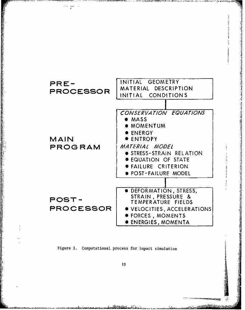
A compact description of the computational process is shown in Figure3. The three stages listed may be incorporated in a single computerprogram, or code, or may exist as three distinct codes. At any rate,some s;ort of automatic generation capability exists to provide adetail.-d computational mesh for the geometry of interest from anabbreviated description provided by the user. This information iscoupled to a description of the materials making up the geometricbodies by specifying appropriate parameters for the equation of state,the stress-strain relationship used by the code in both the elasticand plastic regimes, and the failure criteria to be used. A descriptionof boundary and initial conditions ends this stage of the process. Thepre-processor, as this stage is commonly called, prepares the informationin a form usable by the next part, the main processor, and also prints•
or interactively displays the initial geometry and conditions for userverification. The current crop of codes (those developed within thelast few years) tend to allow the user, via a graphics terminal, toview the results, either complete or partial, of the pre-processor andmodify the computational grid, initial conditions, boundary conditions,and material description.
The conservation laws for mass, momentum and energy, coupled to anequation of state for determination of pressures, a constitutiverelationship, a failure criterion and a post-failure model are cast intofinite difference or finite element form and integrated in time in thenext phase, or main processor, using the information generated by thepre-processor. These computations are of necessity quite long anddemanding of computer storage and except for a very few problems neverrun to completion in one pass. Hence, provision is almost alwaysmade for a restart capability, so that computations may be resumedafter interruption for physical or administrative reasons.
L18
T-I91
PRE- INITIAL GEOMETRYMATERIAL DESCRIPTIONINITIAL CONDITIONS
CONSERVATION EQUATIONS0 MASS* MOMENTUM
0 ENERGYMAIN * ENTROPYPROG RAM A4A,41EWI/,I LM0ODEL
P STRESS-STRAIN RELATION
0 EQUATION OF STATE• FAILURE CRITERION
POST-FAILURE MODELI
* DEFORMATION, STRESS,
POST - STRAIN, PRESSURE &TEMPERATURE FIELDS
PROCESSOR S VELOCITIES,ACCELERATIONS0 FORCES, MOMENTS0 ENERGIES, MOMENTA
Figure 3. Computational process for impact simulation
19
Results of the computations, or output, is generally massive. Codestypically produce full-field descriptions of physical quantities andmaterial conditions (intact, failed, plastically deformed) throughoutthe problem as a function of time. Output listings of two- andthree-dimensional codes can run into hundreds of pages and are impossibleto read (indeed, sometimes to carry). Recourse is therefore made topost-processors, computer programs which prepare graphical displays ofthe items of interest, ie, deformation, velocity, temperature, energyfields at given times, and time histories of variables of interest,etc. The degree of sophistication of these plot packages varies con- Asiderably from code to code. They are also very dependent not only onthe machine on which the zode is installed but also on the installation.Transferring both code and plot package from one installation to anothercan be a nontrivial task. It is not unusual for such transfers to requireseveral man-months of full-time effort.
The decision to use such codes should not be made lightly for inno sense can the current crop of programs be treated as "black boxes"!As a rule, at least three to six months effort is required before newusers can run practical problems on existing codes. During the learn-ing period, frequent contact with the code developers or personsexperienced in their use will be required. Even after the essentialshave been mastered, pathological situations will arise which willrequire guidance from experienced users and may require code modification.Aside from the man-months expended, computational costs will be non-negligible. However, the judicious combination of computer sinmulationsand experiments (which will be accompanied by efforts to characterizecandidate materials at high strain rates if such data is not alreadyavailable) can lead to considerable improvements in engineering designwith reduced manpower and computer costs.
Some examples of results which can be achieved with currentcomputer codes are presented further on. Throughout the following, itshould be kept in mind that computational results are directly relatedto the quality of the material model in the code-the better thedescription of material behavior at the strain rates UI11counteredexperimentally and of its failure modes at those strain rates, thebetter the computational results. Improper materials characterizationleads not only to quantitatively incorrect results but frequently todescriptions which are qualitatively incorrc-L. Imperfect understand-ing of this situation has frequently led to ",..an undesirable iterativeprocedure uf mntching imperfectly understood experiments with theoreticalcomputations based on incomplete models" [26]. Fortunately, this isan area of intense activity currently so that it is not unreasonableto expect that within the next few years improved understanding of thedynamic behavior of materials at ultra-high loading rates will lead toimprovement in code quantitative predictions.
20

After a brief look at various aspects of the numerical simulationof the dynamic behavior of impacting continuous bodies, specificcharacteristics of two- and three-dimensional codes will be mentioned.One-dimensional codes and results will not be considered. For these,the reader will be referred to an extensive literature. The primaryemphasis will be on three-dimensional methods for analysis ofimpacting solids and results.
B. Discretization Methods
It is necessary in a computer analysis to replace a continuousphysical system by a discretized system. In the discretization process,the continuum is replaced by a computational mesh. The discretizationtechniques most commonly used are the finite difference and finite
S~element methods.
Historically, the finite difference codes came first as programswere developed to treat hypervelocity impact situations. Later amaterial strength model, usually a simple elastic-perfectly plasticor rigid plastic model, was tacked on to the codes to treat the laterstages of hypervelocity situations or penetration problems in theordnance velocity regime. Finite element methods began at the oppositeend of the loading rate spectrum, being originally used to approximatethe behavior of arbitrary structures and structural systems subjectedto static loadings. Recently, finite element programs capable oftreating problems in wave propagation, large plastic flow, and fluidflow have appeared and are taking their place with the finitedifference codes.
In the finite difference method, spatial and time grids areconstructed by replacing derivatives in the governing equations ofcontinuum dynamics with difference approximations. Standard techniquesfor solution of large equation sets are employed to obtain spatialsolutions. Solutions in time are obtained by integration.
The finite element approach is an outgrowth of structural analysistechniques. Here, instead of manipulating the governing equationsinto differential equation form and then attempting a numericalsolution, the discretization procedure is employed from the very start.The procedure [27] consists of:
a. dividing the con t inuum by means of imaginary lines into a
finite number of regIu1Ls, or elements, which are assumed to interactonly at a discrete number of points called nodes. The displacementsat these nodal points are the basic unknowns of the problem.
b. a set of functions is postulated to define displacements atany point within an element in terms of the nodal displacement.
21

c. these displacement functions now define a state of strain within Keach element. These, together with constitutive properties, thendefine the state of stress.
d. a system of forces concentrated at the nodes which equilibrateexternal loads is determined. This procedure results in a stiffnessrelationship-equations relating internal loads, external loads, andnodal displacements. Individual element (local) data are thenassembled into global arrays and sulutions for nodal displacements areobtained with conventional techniques for large systems of algebraicequations. Element strains and stresses are then determined from thenodal displacements.
As the above descriptions imply, a common property of both methodsis the local separation of the spatial dependence from the timedependence of the dependent variable. This allows separate treatmentof the space and time grids. Time integration methods will bementioned shortly. Characteristics of the spatial discretizationschemes are discussed in several papers [28-35]. The followingistherefore a brief summary of their principal conclusions.
It has been shown [28] that the discrete forms of the equations ofmotion of the finite element method are equivalent to those of thefinite difference method for a number of cases. Thus, since there isno basic mathematical difference between tne two methods they shouldhave the same degree of accuracy in numerical computations. The maindifferences lie not in the methods themselves but in the datamanagement structure of the computer programs which implement them.
Finite element codes have a distinct advantage in treating irregulargeometries and variations in mesh size and type. This is because inthe finite element method, the equations of motion are formulatedthrough nodal forces for each element and do not depend on the shapeof the neighboring mLsh. In the finite difference method, equationsof motion and expressed directly in terms of the pressure gradientsof the neighboring meshes. This is not inherently a problem, but thedifference equations must be formulated separately for irregularregions and boundaries.
Another major difference occurs in numbering of meshes. In finitedifference programs, the regularity of the mesh implicitly establishesthe connectivity information. In finite element programs, meshconnectivity is explicitly stored, a feature which facilitates automaticgeneration of complex mesh systems. This limitation can be overcomefor finite difference codes, but versatility is generally achievedat the expense of large computer storage and CPU time.
22 L

C. Mesh Descriptions
The bulk of the computer codes for impact studies fall into twocategories: Lagrangian and Eulerian. Lagrangian codes follow themotion of fixed elements of mass with the computational grid beingfixed and distorting with the material. Lagrangian methods haveseveral advantages:
a. the codes are conceptually straightforward since the equationsof mass, momentum, and energy conservation are simpler due to the lackof convective terms to represent mass flow in the coordinate frame.Since fewer computations are required per cycle, they should be intheory computationally faster. However, see below.
b. material interfaces and free surfaces are stationary in thematerial coordinate frame, hence allowing sharp definition and:;traightforward treatment of boundary conditions. It should be notedthough that fairly complex logic is required to define behavior atmaterial interfaces, ie, opening and closing of voids, frictional effects.While such logic enhances the generality and applicability of the codes,a price is paid in the number of additional computations requiredper cycle, thus slowing overall run time.
c. some constitutive equations require time histories of materialbehavior. In the Lagrangian method, this is easily and accuratelyaccounted for.
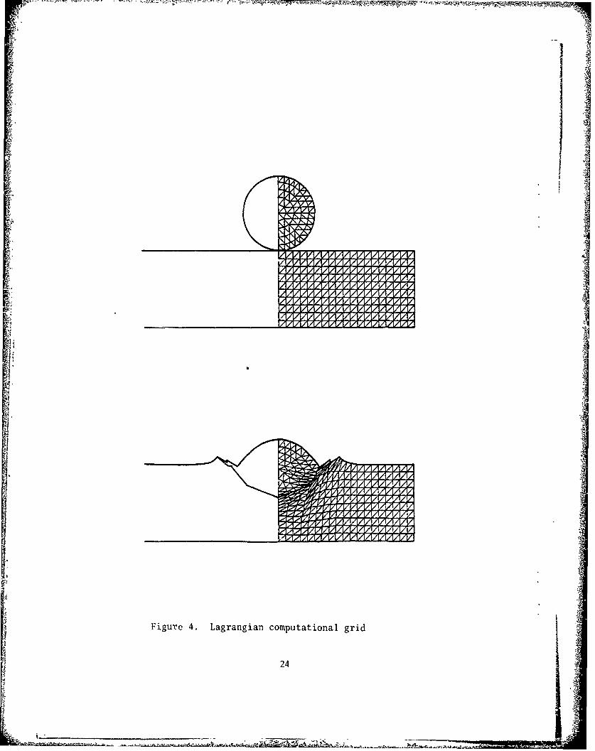
A typical example of a Lagrangian grid is shown in Figure 4.As already mentioned, the Lagrangian computational grid distorts withthe material. Inaccuracies in the numerical approximations growwhen cells become significantly distorted due to shear or fold overthemselves resulting in negative masses. These problems can be overcometo some extent through the use of sliding interfaces and rezoning.
Grid distortions can be reduced in some problems by use of elidinginterfaces either between different materials which can be expectedto slide over one another as the motion proceeds or in regions wherevery large shears and fractures can be expected to develop. Mostsliding interface methods are based on the decomposition ofacceleration and velocity into components normal and tangential tothe interface. Motions in the normal direction are continuouswhen materials are in contact but are independent when they areseparated. Tangential motions are independent when materials areseparated or the interface is frictionless, but are modified if thereis contact and a finite frictional force is present. On slidinginterfaces, frictional forces ranging between zero and infinity maybe specified. Materials at either side of an interface may separateif a specified criterion is exceeded and may collide again ifpreviously separated.
23
!.V~
VVIV
14
i~i
Figure 4. Lagrangian computational grid
24 _ ilt
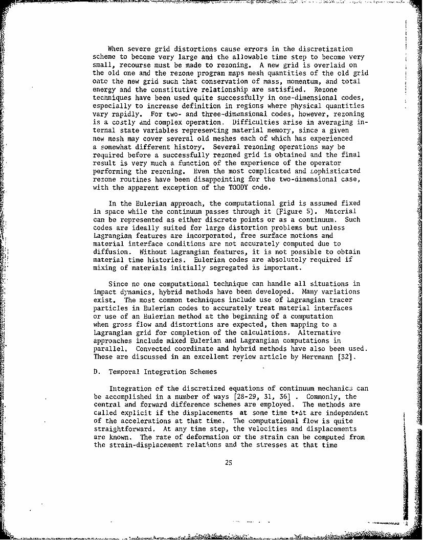
When severe grid distortions cause errors in the discretizationscheme to become very large and the allowable time step to become verysmall, recourse must be made to rezoning. A new grid is overlaid onthe old one and the rezone program maps mesh quantities of the old gridonto the new grid such that conservation of mass, momentum, and totalenergy and the constitutive relationship are satisfied. Rezonetechniques have been used quite successfully in one-dimensional codes,especially to increase definition in regions where physical quantitiesvary rapidly. For two- and three-dimensional codes, however, rezoningis a costly and complex operation, Difficulties arise in averaging in-ternal state variables represemting material memory, since a givennew mesh may cover several old meshes each of which has experienceda somewhat different history. Several rezoning operations may berequired before a successfully rezoned grid is obtained and the finalresult is very much a function of the experience of the operatorperforming the rezoning. Even the most complicated and tophisticatedrezone routines have been disappointing for the two-dimensional case,with the apparent exception of the TOODY code.
In the Eulerian approach, the computational grid is assumed fixedin space while the continuum passes through it (Figure 5). Materialcan be represented as either discrete points or as a continuum. Such
codes are ideally suited for large distortion problems but unlessLagrangian features are incorporated, free surface motions andmaterial interface conditions are not accurately computed due todiffusion. Without Lagrangian features, it is not possible to obtainmaterial time histories. Eulerian codes are absolutely required ifmixing of materials initially segregated is important.
Since no one computational technique can handle all situations inimpact dynamics, hybrid methods have been developed. Many variationsexist. The most common techniques include use of Lagrangian tracerparticles in Eulerian codes to accurately treat material interfaces
or use of an Eulerian method at the beginning of a computationwhen gross flow and distortions are expected, then mapping to aLagrangian grid for completion of the calculations. Alternativeapproaches include mixed Eulerian and Lagrangian computations inparallel, Convected coordinate and hybrid methods have also been used.These are discussed in an excellent review article by Herrmann [32].
D. Temporal Integration Schemes
Integration of the discretized equations of continuum mechanics canbe accomplished in a number of ways [28-29, 31, 36] . Commonly, thecentral and forward difference schemes are employed. The methods arecalled explicit if the displacements at some time t+At are independentof the accelerations at that time. The computational flow is quitestraightforward. At any time step, the velocities and displacementsare known. The rate of deformation or the strain can be computed fromthe strain-displacement relations and the stresses at that time
25

NM
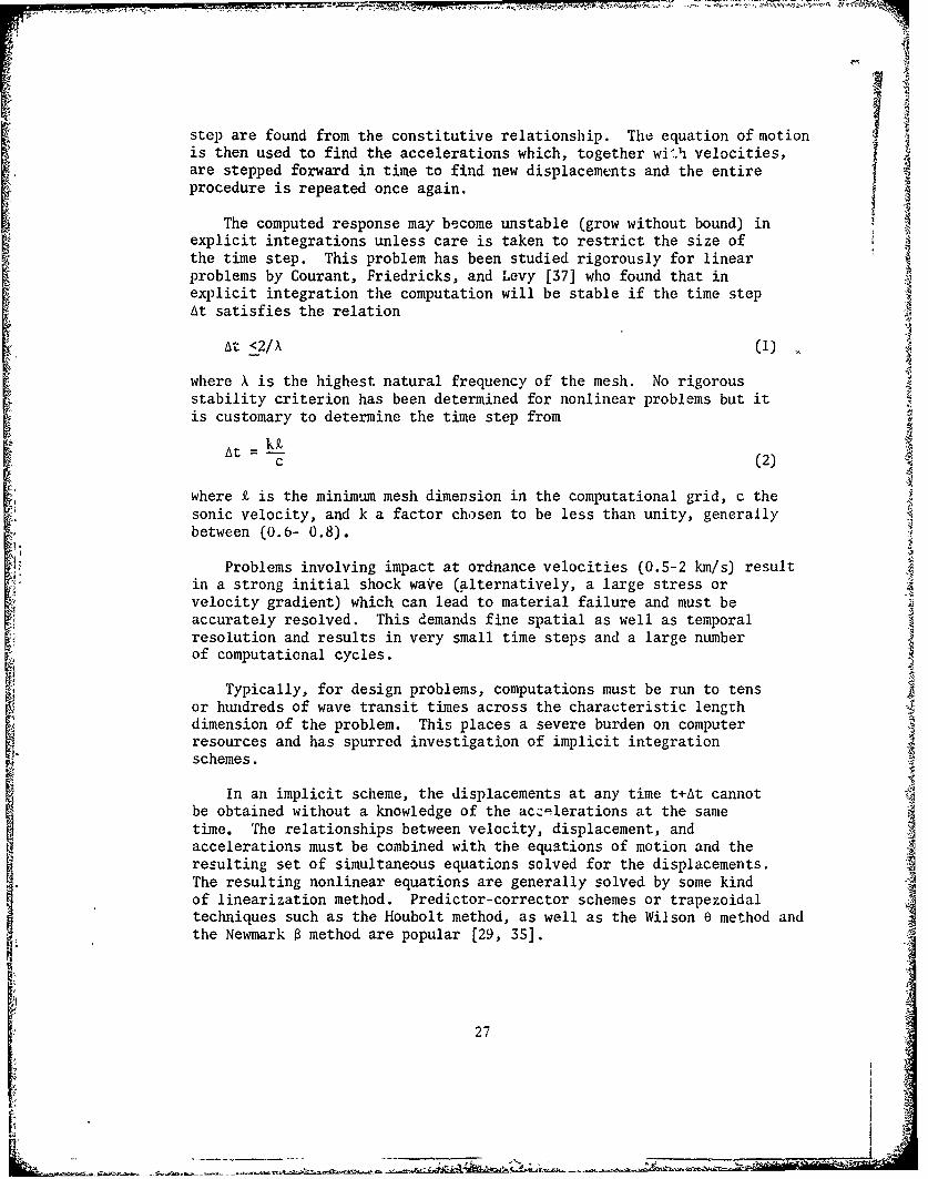
step are found from the constitutive relationship. The equation of motionis then used to find the accelerations which, together wi'h velocities,are stepped forward in time to find new displacements and the entireprocedure is repeated once again.
The computed response may become unstable (grow without bound) inexplicit integrations unless care is taken to restrict the size ofthe time step. This problem has been studied rigorously for linearproblems by Courant, Friedricks, and Levy [37] who found that inexplicit integration the computation will be stable if the time stepAt satisfies the relation
At <2/X (1)
where X is the highest natural frequency of the mesh. No rigorousstability criterion has been determined for nonlinear problems but itis customary to determine the time step from
k£.At = -k 9
C (2)
where £ is the minimum mesh dimension in the computational grid, c thesonic velocity, and k a factor chosen to be less than unity, generallybetween (0.6- 0.8).
Problems involving impact at ordnance velocities (0.5-2 km/s) resultin a strong initial shock wave (alternatively, a large stress orvelocity gradient) which can lead to material failure and must beaccurately resolved. This demands fine spatial as well as temporalresolution and results in very small time steps and a large numberof computational cycles.
Typically, for design problems, computations must be run to tensor hundreds of wave transit times across the characteristic lengthdimension of the problem. This places a severe burden on computerresources and has spurred investigation of implicit integrationschemes.
In an implicit scheme, the displacements at any time t+At cannotbe obtained without a knowledge of the acz-elerations at the sametime. The relationships between velocity, displacement, andaccelerations must be combined with the equations of motion and theresulting set of simultaneous equations solved for the displacements.The resulting nonlinear equations are generally solved by some kindof linearization method. Predictor-corrector schemes or trapezoidaltechniques such as the Houbolt method, as well as the Wilson e method andthe Newmark 0 method are popular [29, 35].
27

Most implicit methods have been shown to be unconditionally stable.
Howeertheprice of stability is teneed to solve a set of equationsat each time step. The local truncation error of most implicit andexplicit schemes is of order (At) 3 . While this is insignificantfor explicit schemes, it is a matter of concern for implicit methodswhere the time step is so much larger.
In general, it has been found [30, 31, 36] that for wavepropagation methods, the time step for implicit methods must be aboutthe same as that for explicit methods in order to satisfy accuracyrequirements. Since implicit methods require considerably morecomputations per cycle than explicit integrations, their use hasgenerally been limited to problems where the details of wavepropagation are not as significant as the overall response of thematerial.
E. Computer Resource Requirements
questions of accuracy and resolution required for dynamic stresswave solutions are discussed in [36]. Such solutions arec'iaracterized by a very high frequency content and adequate numericalrepresentation requires a large number of meshes in areas where largestress gradients propagate. Two-dimensional computations areroutinely done with 4,000-10,000 meshes or elements. Adequateresolution in three-dimensional problems is even more difficult toachieve. For practical problems 20,000-50,000 meshes are not uncommon.For high velocity impact situations, adequate information for designpurposes (projectile velocity and orientation, extent of deformationin projectile and target, energy deposition in the target) may beobtained with 20-25,000 meshes. Excellent correlation with experimentwas obtained for an oblique impact situation with 25,000 elements [ 3]while the same calculation with 12,000 elements underpredicted penetrationdepth by 40%. For problems involving steep gradients or advancedfailure models, even greater resolution may be required. Since mostpractical problems are run with variable meshes to conserve CPU timeand computer storage, there is no a priori method for determining anoptimum grid for a given computation, although guidelines for educatedguesses exist [30, 36]. Experienced code users can generally arriveat acceptable grids within a few iterations.
Computing costs tend to be quite high for production problems.Running times for one-dimensional codes are measured in minutes.For two-dimensional codes with some 5-6000 meshes or elements, runningtimes of several hours on CDC 7600 class machines are typical.Three-dimensional problems will typically run from 4-10 hours or
longer. Three-dimensional problems also rllace severe limitations oncomputer storage. It is virtually impossible to run a three dimensionalimpact problem totally in-core. Thus, to permit adequate resolution,most codes have provisions for keeping only a small portion of thegrid in core and the remaining information on a mass memory device.
28

There is still an upper limit on resolution, though. If the numberof meshes or elements is too great, the bulk of the total computertime will be spent in data transfer and very little in advancingcomputations.
As expensive as such calculations may be, they are often lesscostly than full-scale experiments. Indeed, in certain situations,experimentation may not be possible and reliance must be made oncomputations. Additionally, unless the software is reasonablyefficient in permittting automated mesh generation and graphicalrepresentation of results, the major portion of the total cost willbe associated with manpower charges incurred by analysts performingnumerical studies. An illuminating example is shown in [36].
F. Material Model
It is common in existing production codes for the study of highvelocity impact phenomena to divide the deformation behavior of metalsinto volumetric and shear (deviatoric) parts. Metals undergo plasticyielding at modest levels of deviator flow stress. This is usuallytaken to be independent of pressure, so that the volumetric behaviorcan be treated independently of the shear behavior.
The volumetric behavior is described in terms of an equation ofstate relating pressure, volume and some thermal p:.raneter, usuallythe internal energy or temperature. The Mie-Gruneisen equation ofstate is frequently used, although some codes allow a choice ofequations. In the newer, modular, codes, equations of state canreadily bu changed.
For solid-solid impacts in the 0.5-2 km/s velocity regime, onlymoderate pressures (300-500 kb) are generated and these decay rapidlyto values comparable to the strength of the material. Hence, theequation of state in impact calculations is of secondary importance.Considerable data exists for the current crop of equations in variouscompilations for most metals of interest [38-39] and additional datacan readily be obtained. Consequently, the state of the art inequation of state is adequate for most present needs.
An incremental elastic-plastic formulation is used to describethe shear response of metals in present finite difference and finite
element codes. The plasticity descriptions are usually based on anassumed decomposition of the velocity strain tensor, 6, intoelastic and plastic parts
e 6e+,p (3)
together with incompressibility of the plastic part
e OP +6p = 0 (4)11 22 33
29
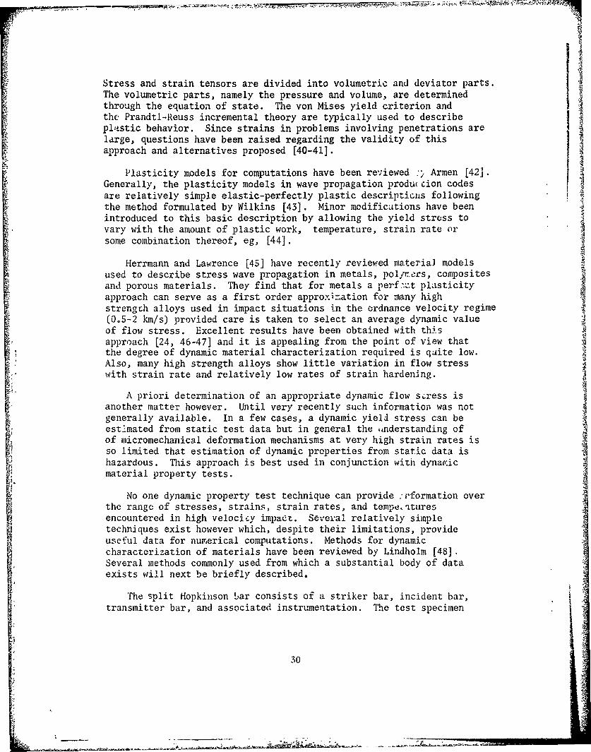
Stress and strain tensors are divided into volumetric and deviator parts.The volumetric parts, namely the pressure and volume, are determinedthrough the equation of state. The von Mises yield criterion andthe Prandtl-Reuss incremental theory are typically used to describepl-istic behavior. Since strains in problems involving penetrations arelarge, questions have been raised regarding the validity of thisapproach and alternatives proposed [40-41].
Plasticity models for computations have been reviewed :ý Armen [42].Generally, the plasticity models in wave propagation produ cion codesare relatively simple elastic-perfectly plastic descriptiGIis following
the method formulated by Wilkins [43]. Minor modifications have beenintroduced to this basic description by allowing the yield stress tovary with the amount of plastic work, temperature, strain rate orsome combination thereof, eg, [44].
Herrmann and Lawrence [45] have recently reviewed materiai modelsused to describe stress wave propagation in metals, pol/rers, compositesand porous materials. They find that for metals a perf.-t plasticityapproach can serve as a first order approximation for many highstrength alloys used in impact situations in the ordnance velocity regime(0.5-2 km/s) provided care is taken to select an average dynamic valueof flow stress. Excellent results have been obtained with thi's
- approach [24, 46-47] and it is appealing from the point of view thatthe degree of dynamic material characterization required is qaite low.Also, many high strength alloys show little variation in flow stresswith strain rate and relatively low rates of strain hardening.
A priori determination of an appropriate dynamic flow scress isanother matter however. Until very recently such information was notgenerally available. In a few cases, a dynamic yield stress can beestimated from static test data but in general the ,nderstanding ofof micromechanical deformation mechanisms at very high strain rates isso limited that estimation of dynamic properties from static data ishazardous. This approach is best used in conjunction with dynap:ic
material property tests.
No one dynamic property test technique can provide :i'formation overthe range of stresses, strains, strain rates, and temperaturesencountered in high velociLy impact. Several relatively simple
techniques exist however which, despite their limitations, provideuseful data for numerical computations. Methods for dynamiccharacterization of materials have been reviewed by Lindholm [48].Several methods commonly used from which a substantial body of dataexists will next be briefly described.
"The split Hopkinson bar consists of a striker bar, incident bar,transmitter bar, and associated instrumentation. The test specimen
30

is sandwiched between the incident and transmitter bar. Measurementof the elastic waves in the pressure bars which are reflected andtransmitted by the specimen yield average stress, strain, and strainrate as functions of time in the specimen once the specimen has reachedhomogeneous deformation. This data can be manipulated to obtain adynamic stress-strain curve for the specimen material. The techniquecan be employed in tension, torsion, and compression at strain ratesfrom 102 to 104 s-1 [48-53].
Care must be taken in performing split-Hopkinson bar tests thatassumptions governing analysis of the data not be violated. Thepressure bars and specimen are assumed to be in a state of uniaxialstress so that radial inertia effects are neglected. Care must also
be taken in selecting specimen size and lubrication of specimen-barinterfaces to minimize end effects.
An alternate method involves the free-flight impact of identicalbars [54-56] producing a well-defined constant velocity boundarycondition and an accurate measurement of surface strain by opticaltechniques employing diffraction grati~ngs ruled directly on the
specimen. The technique was perfected by Professor James Bell ofJohns Hopkins University. For each test, a record of surface strainand surface angle is made. From a series of such tests, Bell constructsof propagation of each increment of plastic strain is constant. This
requires measurement of strain-time profiles at several axialpositions along the length of the bar. If the average propagationvelocities are indeed found to be constant it is a sufficient conditionfor the one-dimensional rate-independent theory of plasticity tohold [57] and permits determination of stress corresponding to agiven strain to be obtained.
This technique also has a number of limitations which have been
more fully discussed elsewhere [48, 58]. Radial inertia effects nearthe end of the struck specimen are unavoidable and confuse interpretationof measurements.
Another technique, originally used by Taylor [59] and Whiffen [60],consists of firing a short cylindrical bar against a rigid surface.The struck end of the bar is subjected to large plastic strains andcomplex stress states. However, a simple analysis [59], laterrefined by Hawkyard [61], permits determination of an average dynamicyield stress in terms of the impact velocity and the residual lengthof the bar. Wilkins and Guinan [46] have examined the methodin detail using the two-dimensional HEMP code. They find that overallagreement with experimentally determined deformation profiles can bedetermined with the dynamic average flow stress so obtained and thatthe flow stress for a number of materials was invariant over a limitedrange of strain rates.
31

If information at higher strain rates is needed, recourse mustbe made to plate impact experiments. Impact of a flat projectileon a flat target plate produces plane stress waves in which, becauseof symmetry, the strain is one-dimensional until reflections arrivefrom the plate edges. Strain rates from about 104-106 s-1 can be studiedwith this technique. Reviews have been given by Karnes [62] and Davisonand Graham [63].
Provided care is taken to characterize materials at strain ratesappropriate to problems being considered, excellent results can beobtained even with simple material models. The greatest limitationon the utility of computations for studying impact processes is inthe modeling of material failure. Because of its importance, thistopic will be treated separately. Next, a brief survey is given ofthe characceristics of currently popular two- and three-dimensionalcomputer codes together with examples of their capabilities.One-dimensional codes and two-dimensional codes of historical interestwill not be mentioned since these have already been extensivelyreviewed [26, 30-33, 64].
III. CURRENT CODE CAPABILITIES
A. Two-dimensional Lagrangian Codes
The most prominent two-dimensional finite difference Lagrangiancodes in use today are the HEMP code, developed by Wilkins of LawrenceLivermore Laboratories, and the TOODY/TOOREZ codes developed byBertholf and his colleagues at Sandia Laboratories. Both codes employa second order accurate finite difference representation firstdeveloped by Wilkins [42]. They are quite similar in essentialfeatures and capabilities. Both codes are well documented insofaras the fundamentals are concerned [65-69]. However, there are many
-4versions of both codes running on a variety of machines. Potentialusers are therefore well advised to obtain not only the basicdocumentation but also to maintain close contacts with the users andsystems people at the computer center from which their particularversion is obtained. Many derivatives of HEMP exist, ie, thetwo-dimensional member of the PISCES family of codes marketed byPhysics International through the CDC Cybernet network, CRAM and SHEPto name a few. The differences relate primarily to features requiredto implement the basic code on different machines and changes inpre- and post-processing capability.
The finite difference equations in the HEMP QHydrodynamic, Elastic,Magneto & Plastic) code, employ a quadrilateral grid and may be solvedin plane coordinates or with cylindrical symmetry. Slide lines areavailable which permit material motion with and without friction.Provision is also made for the opening and closing of voids. Boundariesmay be fixed or free, stationary or moving. Both pressure and velocity
32

initial conditions may be specified. A mesh generation capabilityexists so that many geometric configurations may be generated withminimum user input. Alternatively, users may specify mesh configurationswith a fair degree of detail manually.
The HEMP code runs on a variety of computers, though most userstend to prefer the CDC 6600 and 7600 machines. The precise configurationof the code and size of problems which can be run depend very much onthe machine on which it is implemented.
The TOODY-TOOREZ codes are similar in the basics to HEMP. Thefinite difference equations in the TOODY code are discussed in somedetail by Walsh [3.]. Like HEMP, TOODY has been used successfully ona number of difficult practical problems. As with most productioncodes, instantaneous failure criteria based on maxima or minima of fieldvariables were initially incorporated in the codes. Many usershowever have modified these and incorporated more sophisticated failuremodels to suit their particular needs.
The EPIC-2 (Elastic Plastic Impact Calculations in 2 Dimensions)code [70] is based on a Lagrangian finite element formulation whereinthe equations of motion are integrated directly rather than throughthe traditional stiffness matrix approach. The code treats problemsinvolving wave propagation and elastic-plastic flow. It is arrangedto provide solutions for projectile-target impacts and explosivedetonation problems. Material descriptions are incorporated whichinclude the effects of strain hardening, strain rate effects, thermalsoftening, fracture, and spin. Geometry generators are included topermit quick generation of flat plates, spheres, and rods with blunt,rounded or conical nose shapes. Multiple slide lines (no frictionaleffects) are provided. A rudimentary post-processor provides plotsof initial geometry, deformed geometry, effective stress, effectivestrain, pressure, and velocity fields. In addition, time-historyplots of various system parameters (energies, momenta, penetrationdepth, etc.) may be obtained.
B. Two-dimensional Eulerian Codes
Two Eulerian codes currently popular for impact studies whichincorporate all the desirable features of the Eulerian descriptionof continuous material behavior while including features which enhancematerial interface and boundary definition are HELP and HULL.
The HELP code was developed by L. J. Hageman and J. M. Walsh.The current version [71] is a two-dimensional, multi-material firstorder finite difference code which has been used extensively to solvematerial flow problems in the hydrodynamic and elastic-plastic regimes.Although the code is basically Eulerian, material interfaces and free
33
!iI
41
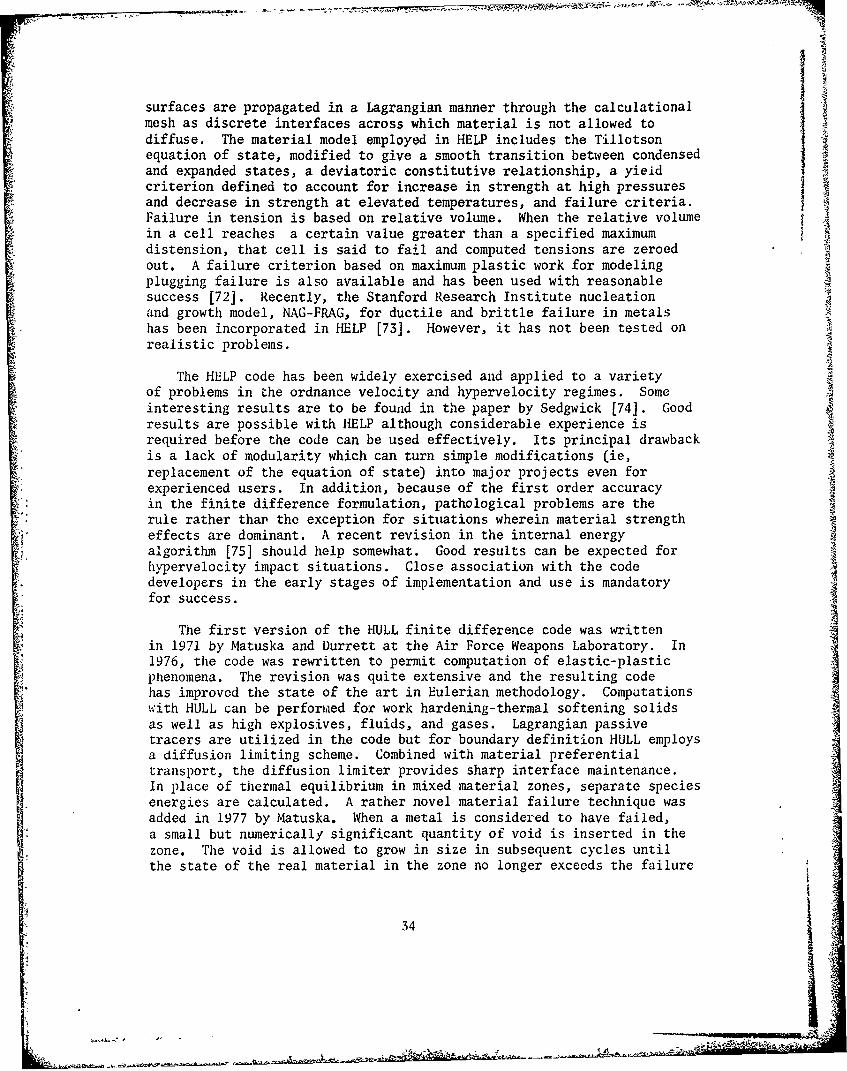
surfaces are propagated in a Lagrangian manner through the calculationalmesh as discrete interfaces across which material is not allowed todiffuse. The material model employed in HELP includes the Tillotsonequation of state, modified to give a smooth transition between condensedand expanded states, a deviatoric constitutive relationship, a yield"criterion defined to account for increase in strength at high pressuresand decrease in strength at elevated temperatures, and failure criteria.Failure in tension is based on relative volume. When the relative volumein a cell reaches a certain value greater than a specified maximumdistension, that cell is said to fail and computed tensions are zeroedout. A failure criterion based on maximum plastic work for modelingplugging failure is also available and has been used with reasonablesuccess [72]. Recently, the Stanford Research Institute nucleationand growth model, NAG-FRAG, for ductile and brittle failure in metalshas been incorporated in HELP [73]. However, it has not been tested onrealistic problems.
The HELP code has been widely exercised and applied to a varietyof problems in the ordnance velocity and hypervelocity regimes. Someinteresting results are to be found in the paper by Sedgwick [74]. Goodresults are possible with HELP although considerable experience isrequired before the code can be used effectively. Its principal drawbackis a lack of modularity which can turn simple modifications (ie,replacement of the equation of state) into major projects even forexperienced users. In addition, because of the first order accuracyin the finite difference formulation, pathological problems are the"rule rather than the exception for situations wherein material strengtheffects are dominant. A recent revision in the internal energyalgorithm [75] should help somewhat. Good results can be expected forhypervelocity impact situations. Close association with the codedevelopers in the early stages of implementation and use is mandatoryfor success.
The first version of the HULL finite difference code was writtenin 1971 by Matuska and Durrett at the Air Force Weapons Laboratory. In1976, the code was rewritten to permit computation of elastic-plasticphenomena. The revision was quite extensive and the resulting codehas improved the state of the art in Eulerian methodology. Computationswith HULL can be performed for work hardening-thermal softening solidsas well as high explosives, fluids, and gases. Lagrangian passivetracers are utilized in the code but for boundary definition HULL employsa diffusion limiting scheme. Combined with material preferentialtransport, the diffusion limiter provides sharp interface maintenance.In place of thermal equilibrium in mixed material zones, separate speciesenergies are calculated. A rather novel material failure technique wasadded in 1977 by Matuska. When a metal is considered to have failed,a small but numerically significant quantity of void is inserted in thezone. The void is allowed to grow in size in subsequent cycles untilthe state of the real material in the zone no longer exceeds the failure
34
criterion. The void can completely take over a zone or neighboringzones if the physical situation decrees such growth necessary, ie, spall.Zone recompression car, reduce the size of voids or eliminate themaltogether. Excellent results with HULL have been obtained at the AirForce Armament Laboratory, Eglin AFB on formidable practical problemsinvolving penetration of thick targets and target arrays. The HULL coderuns on CDC 6600 and 7600 computers as well as Honeywell and IBM machinesand has considerable flexibility in input preparation and displaysof results. Documentation, however, is spartan [76-77]. Assistancefrom experienced users or code developers is virtually mandatory untiladditional documentation becomes available.
Other Eulerian codes used frequently for impact situations are DORF[78-79J which is quite similar to HELP in capabilities and problemsand also CSQ [80-81] which is frequently used in conjunction with theTOODY code to guide rezoning operations. Typical results are to befound in [82].
C. Three-dimensional Codes
A number of three-dimensional codes are available. With exceptionsto be noted below, they are based on their two-dimensional predecessors,the general features of which are described above and in review articles[26, 32, 64].
The Lagrangian finite difference code HEMP3D [83] is an outgrowthof the two-dimensional HEMP code and is designed to olve problemsin solid mechanics involving dynamic plasticity and time-dependent
A:C material behavior. It is based on an incremental formulation forelasto-plastic behavior, employs the von Mises yield criterion andrelies on artificial viscosity for diffusion of steep shock fronts.The code has been applied to a variety of static and dynamic problems,including fracture [84-86]. It is being extended to include slidingsurfaces for treatment of penetration problems.
TRIOIL and TRIDORF are both Eulerian three-dimensional finitedifference codes, developed by W. E. Johnson [87-88]. They have beenapplied to the study of shaped charge penetration of finite thicknessplates (with the jet modeled as a rigid rod) at high obliquity as well
as other problems. Both codes are similar to their predecessors, OILand DORF, except that TRIDORF is a two-material code with a rigid plasticstrength formulation. Similar in spirit is METRIC, developed byHageman et al [89-90]. The numerical methods and material descriptionsare similar to those employed in HELP, its forerunner. The code isnot core-contained so that in theory it can provide any degree of spatialresolution. In its initial development, METRIC relied on mixed cells(cells containing more than one material) to establish materialboundaries. The code was eventually modified and now material interfacesand free surfaces are defined by massless tracer particles, just as inthe HELP code.
35
__ _ _ _ _ _

Finite element methods based on Eulerian material descriptionsare under development by Reddy [91-92] and Chan et al [93]. Thelatter have developed models that include visco-plastic and strainrate effects and account for material failure. Impact is viewed asa problem in the structural response class and the ultimate goal isthe coupling of the Eulerian impact model with a Lagrangian structuralresponse code such as NASTRAN.
The EPIC-3 code developed by G. R. Johnson [94-97] of HoneywellI is based on a Lagrangian finite element lumped mass formulationemploying tetrahedron elements. As with its two-dimensional analog,EPIC-2, the equations of motion are integrated directly, bypassingthe traditional stiffness matrix approach. A fairly comprehensiveI material description capability exists, allowing for strain hardening,strain rate effects, thermal softening, and fracture. Geometrygenerators are included to quickly generate flat plates and rods withvarious nose shapes. Unlike conventional finite element schemes, thefirst version of EPIC-3 did not require an orderly grid.
In later versions [98], the EPIC-3 code has been restructured intothree separate programs: a pre-processor, main processor, andpost-processor. All are connected by a common restart tape. Providedthat the nodal bandwidth can be core-contained, problems of unlimitedsize can in theory be run. In practice, there is an upper limit tothe problem size tractable since as disc storage becomes large, thereis a tendency for the machine to spend most of its running time indata transfers and very little in computation. Cost is also a non-negligible constraint. For smaller problems, where all nodes can becore-contained, an option is provided to bypass this buffering. EPIC-3has been programmed to eventually run on fourth-generation vectorcomputers and should run somewhat faster than the first version oncomputers which have some vectorization features.
The newer version has expanded sliding surface capability whichincludes frictional effects, an improved pre-processing capabilitywhich cuts down oa user input for slide line and geometry definitionand the added capability to automatically generate solid and hollowrods with various nose shapes as well as solid and hollow spheres.Pressure as well as velocity initial conditions may be specified inthe updated version. Further developments [99] have resulted in
an improved post-processing package, provision for elasto-plasticF analysis of orthotropic materials, and incorporation of a material
model for treatment of impact into concrete and other geologicalmaterials. Anisotropic features are also available in TOODY [100]"and in the HELP code [101].
Current developments in this area are noteworthy Two- andthree-dimensional codes using implicit (NIKE2D, NIKE3D) and explicit(DYNA2D, DYNA3D) integration schemes have been developed byJ. 0. Hallquist [102-107] for solution of problems involving lar c.strains and deformations. Spatial discretization can ýI, accomplished
36

in a variety of ways. DYNA2D, for example, permits a choice of constantstress finite elements that can be degenerated into triangular zones,constant pressure variable node elements, nine-node Lagrangian elementsor finite difference zones based on the HEMP difference equations. Ageneral slide line capability is implemented that admits frictionalsliding along arbitrary, intersecting grid lines. Loading functionsadmit pressure and shear loadings along a boundary, body force loadingsdue to spinning and base accelerations and nodal velocity-timehistories. An impressive solution to a difficult problem (deformationof an aluminum rod with length-to-diameter ratio of 48 striking asteel plate at 200 m/s and 100 obliquity) is shown in [104].
The above list is by no means complete. It serves mainly toindicate the types of codes available and the range of problems whichcan be addressed. The previously cited references should be consultedfor a more comprehensive listing and description.
It is not possible to review here the spectrum of calculationswhich have been done with existing codes. Rather, in the next section,examples of three-dimensional calculations performed at the US ArmyBallistic Research Laboratory are presented.
IV. EXAMPLES
A. Sphere Ricochet
In certain impact situations it becomes necessary to account forthe effects of friction on the motion of colliding bodies. Figure 6shows isometric plots of EPIC-3 results for the case of an SAE 52100steel sphere, 0.635cm in diameter, striking a 2024-T3510 aluminumplate, 0.635cm thick at an obliquity of 600 from the plate normal ata velocity of 720 m/s. Experimental data for this problem isgiven by Backman and Finnegan [108]. The problem was first addressed Z4computationally by G. R. Johnson [96] with the early version ofEPIC-3 using a frictionless sliding interface. Despite a very coarsegrid, good agreement was obtained for the deformed profile of targetplate. The present calculation was done with a finer grid (5202 nodesand 24576 elements) with the current version of EPIC-3. A computa- "
tion was also made with a grid consisting of 14768 nodes and 75168elements, but results did not differ appreciably from the identicalcase with the 24576 element configuration.
The variation of projectile velocity with time and sliding frictioncoefficient is shown in Figure 7. For the frictionless interface,the computed residual velocity differs by some 38% from the valueof 303 m/s reported by Backman and Finnegan. Progressive increasein the surface friction coefficient reduces the residual velocity ofthe sphere (and imparts a correspondingly greater spin to it). 'Ate5% friction, the computed residual velocity of 318 m/s differs by
less than 5% from that reported experimentally. The deformationpattern in the target is little affected by the frictional interfaceand is substantially the same for all cases.
37
* - - -- 2 - -
a I
'44
10fl riroecBd
[ 15 Microseconds
150 Microseconds
Figure 6. Deformation profiles for oblique impact of steel
sphere into aluminum target at various times
3) 0

NI
L 02 L Al LAlC3 N N - toNr
' U.'
MA 02 M
Lan
ULU
Ex
M I
ILI
U.:.
Ln
M tr
T IM
CEIW) AD1, i3A
Figure 7. Velocity histories for oblique impact of steel sphereinto aluminum target
39

In actual fact, the surface friction effect would be a functionof the relative velocity of the impacting bodies. It is unlikely tobe significant at impact velocities >1 km/s where very high pressuresare generated at the impact interface producing a thin layer ofmaterial which acts as a fluid. At lower velocities and for drawingand punching problems frictional effects can be significant. Estimatesof frictional coefficients are not easily obtained, however. In arecent paper [109] Ghosh determined the coefficient of frictionfor sheets of various materials being struck by a hemispherical steelpunch. Average values of the coefficient of friction were calculatedfor a number of materials under various conditions of lubrication.The aluminum alloys con3idered were 2036-T4, 3003-0, and 5182-0aluminum. The calculated coefficient of friction for these alloysranged from 0.22-0.41 for the dry state and from 0.07-0.27 for testpieces coated with Teflon and polyethylene. With these results inmind and the close agreement with experiment for projectile residualvelocity and target deformed shape, it is proper to conclude thatEPIC-3 results are a quite reasonable approximation of the principalfeatures of the impact event.
All the computations were done on a CDC 7600 computer. Typicalrunning times for all but the fine grid problems were just under twohours.
B. Yawed Rod Tmpact
!t is now well established that impact encounters at large yawangles seriously degrade the performance of long rod strikers 1110].Knowledge of the deformations and stress states which occur undersuch conditions can prove valuable in understanding rod behavior andimproving projectile design.
The specific problem considered here involves the impact of a2024-T3510 aluminum rod (length 5.57cm, diameter 0.635cm) by acircular plate (diameter 10.16cm, thickness 1.27cm) of rolled homo-geneous armor at a velocity of 550 m/s. The rod was suspended bytungsten wires in a plastic frame at an angle of 450. A four inchgas gun was used to launch the plate against the stationary rod. Axenon flash source ý:as used for back lighting and the eventphotographed at two microsecond intervals with a Cordin model 330framing camera.
Figure 8 shows a comparison of experimentally recorded deformationprofiles with those computed uy EPIC-3 at two differert times. Atotal of 1992 nodes and 8304 tetrahedral elements were used for thecalculation. The agreement is gencrally excellent. For the latertime, it is seen that the curvature of the deformed portion of therod does not quite match that shown in the framing camera
40
le
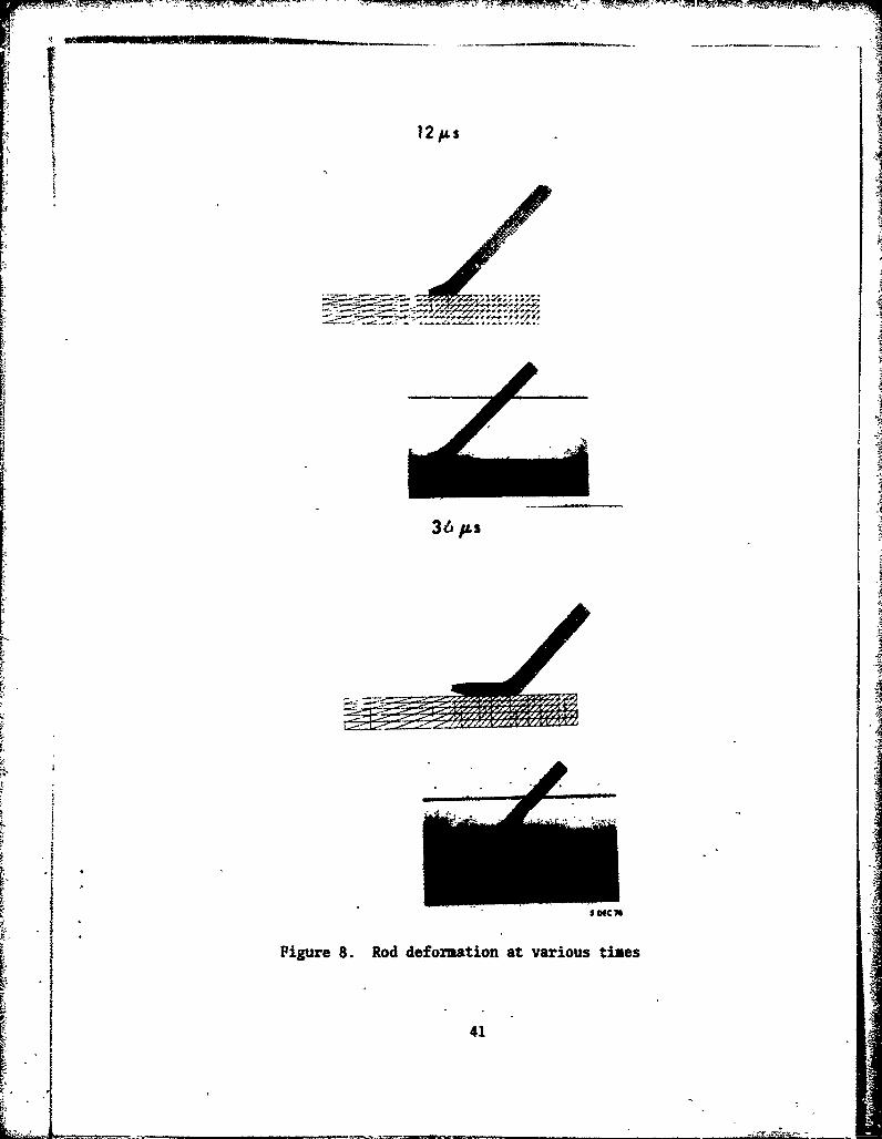
12,IA.s
36 ps
So
Figure 8. Rod deformation at various times
41
36t
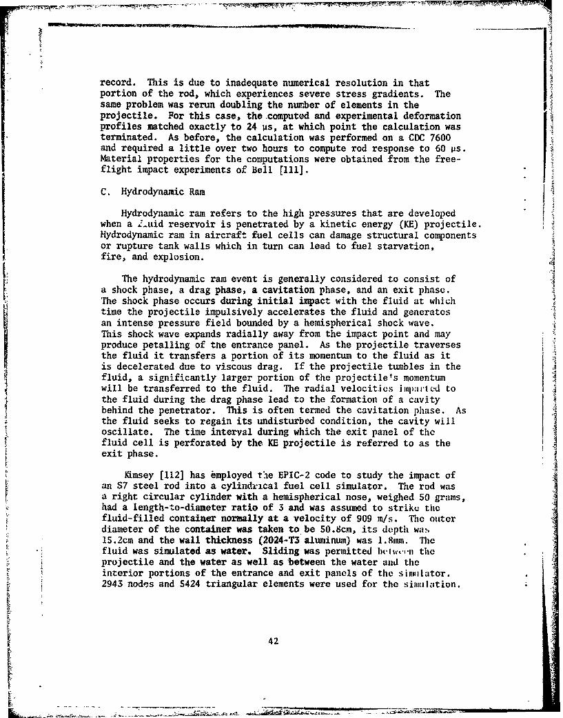
record. This is due to inadequate numerical resolution in thatportion of the rod, which experiences severe stress gradients. Thesame problem was rerun doubling the number of elements in theprojectile. For this case, the computed and experimental deformationprofiles matched exactly to 24 ps, at which point the calculation wasterminated. As before, the calculation was performed on a CDC 7600and required a little over two hours to compute rod response to 60 ps.Material properties for the computations were obtained from the free-flight impact experiments of Bell [111].
C. Hydrodynamic Ram
Hydrodynamic ram refers to the high pressures that are developedwhen a .'-uid reservoir is penetrated by a kinetic energy (KE) projectile.Hydrodynamic ram in aircraft fuel cells can damage structural componentsor rupture tank walls which in turn can lead to fuel starvation,fire, and explosion.
The hydrodynamic ram event is generally considered to consist ofa shock phase, a drag phase, a cavitation phase, and an exit phase.The shock phase occurs during initial impact with the fluid at whichtime the projectile impulsively accelerates the fluid and generatesan intense pressure field bounded by a hemispherical shock wave.This shock wave expands radially away from the impact point and mayproduce petalling of the entrance panel. As the projectile traversesthe fluid it transfers a portion of its momentum to the fluid as itis decelerated due to viscous drag. If the projectile tumbles in thefluid, a significantly larger portion of the projectile's momentumwill be transferred to the fluid. The radial velocities jiiijipi,,'d tothe fluid during the drag phase lead to the formation of a cavitybehind the penetrator. This is often termed the cavitation phase. Asthe fluid seeks to regain its undisturbed condition, the cavity willoscillate. The time interval during which the exit panel of thefluid cell is perforated by the KE projectile is referred to as theexit phase.
Kimsey [112] has employed the EPIC-2 code to study the impact ofan S7 steel rod into a cylindrical fuel cell simulator. The rod wasa right circular cylinder with a hemispherical nose, weighed 50 grams,had a length-to-diameter ratio of 3 and was assumed to strike thefluid-filled container normally at a velocity of 909 m/s. The outerdiameter of the container was taken to be 50.8cm, its depth wa.s15.2cm and the wall thickness (2024-T3 aluminum) was 1.8mm. Thefluid was simulated as water. Sliding was permitted iwitwov.,. theprojectile and the water as well as between the water and theinterior portions of the entrance and exit panels of the sinmlator.2943 nodes and 5424 triangular elements were used for the simulation.
42
Deformation and pressure profiles at 40 and 180 us after impact(112] are shown in Figure 9. The impulsive acceleration of thefluid during the shock phase ( 10 Vs after impact) generates peakpressures of 280 MPa, which decay rapidly to 14 MPa and persist atabout that level during the drag phase. Petalling of the entrancepanel due to the action of the water is also evident. By 180 us,the exit panel has been sufficiently loaded to initiate bulging priorto perforation. The entrance panel has been deflected considerablyand an additional cavity between the entrance panel and the water hasformed. The cavity formed behind the water was formed by permittingtotal failure of elements which exceed an equivalent strain of 2.5.
No experimental data for this case was found. However, Kimseywas able to compare the predicted residual velocity from EPIC-2 withthat determined from an empirical relationship derived on the basisof a number of hydrodynamic ram experiments. The two valuesdiffered by 4%.
V. COMPUTATIONAL FAILURE MODELS
The most serious limitation to extensive use of computationaltechniques described above arises not from their cost or complexity(ballistic experiments are neither less costly nor less complex)but from the inadequacy of the models describing material failure.Under dynamic loading, failure can occur by a variety of mechanismsdependent on the material constitution and the state of stress,temperature, rate of loading, and a number of other variables. Themethods and results of quasi-static fracture studies are of littleuse in situations involving high rate loading.
Simple empirical failure models of varying degrees of complexityexist. Some have been applied successfully in high velocity impactcalculations. For the most part, though, failure criteria and modelsare of an ad hoc nature, lacking a micromechanical basis to treatcomprehensively problems involving brittle, ductile, and shearfailure. Different criteria apply for different impact conditionsand there are at present no guidelines to analysts for selecting anappropriate failure criterion under different conditions.
Computational failure models for impact loading situations are
discussed in receat review articles [113, 3] and in some depth in areport by the National Materials Advisory Board Committeeon Materials Response to UltraHigh Loading Rates [114]. Hence, thefollowing remarks are intended to summarize the current state ofaffairs in numerically simulating material failure. The citedreferences should be consulted for additional details.
It is now generally accepted that material failure under impactloading is a time-dependent phenomenon. Experimental observationslead to the following conclusions about the general features ofmaterials failure (113]:
43

PRESSURE CONTOURSTIME Op~sAT TIME 4O04s
TIME 40I* 14MWeA7M~c
N .99
-- '
-13--13
177 7 .3-7 -3 1A AXIS ICM) W7
It AXIS (cm) S&v 7.
PRESSURE CONTOURSTIME 18$Oju AT TIME 18O1ts
~10
1 3 - 1 3 -
-17 -
-7. 7-3 -15-
Figure 9. DefornationS and pressiares in fuel tank simulatorat 40 to 180 vnn
44 -4
a. a range of damage is possible; there is no instantaneous jumpfrom undamaged to fully separated material.
b. damage grows as a function of time and the applied stress.Hence, a single field variable of continuum mechanics (stress, strain,plastic work, etc.) at any time cannot be expected to characterizethe dynamic fracture process. At least some time-integral quantitymust be used to represent the dynamic strength. Of course, if theintensity of the applied load is so severe that the damage occurs innegligibly short time, reasonable results may be expected frominstantaneous failure criteria.
c. as the level of damage increases, the material is weakenedand its stiffness reduced. This changes the character of the wavepropagation through the material. Ideally4 this should be accountedfor in computational procedures.
d. even incipient damage levels are important since voids orcracks, difficult though they may be to ooserve, may seriously weakena structure.
There are a number of failure descriptions used in currentproduction codes. They involve an initiation criterion and somedescription of the post-failure behavior.
The simplest of the initiation criteria are based on instantaneousvalues of a field variable, such as pressure, stress, strain, plasticwork, or some combination thereof. Once the criterion has beensatisfied at a given location, failure is considered to occurinstantaneously. The post-failure response can be described in anumber of ways. The failed material may be entirely removed from thecomputation or be described by a modified constitutive function whichdescribes a weakened material.
One of the simplest of such models, for example, is the pressurecutoff. When the hydrostatic pressure reaches a critical tensilevalue (or zero), failure is assumed to occur instantaneously.Further expansion occurs at that fixed value of pressure. Ifsubsequently recompression occurs, compressive pressures are againallowed. More complicated versions of this basic approach have beenimplemented. Excellent results have been obtained with criticalstress criteria [24] for hypervelocity impact situations wheredynamic tensile spall situations exist.
Time-depeadent initiation criteria represent the next level ofsophistication and have been successfully applied in several situations.One of the earliest is due to Tuler and Butcher ( 115]. Failure isassumed to occur instantaneously when a critical value of the damageK, defined by the integral
K (u-ao) 0) dtS.00
4S
is reached. Here a(t) is a tensile stress pulse of arbitrary shape, aa threshold stress level below which no significant damage will ooccur regardless of stress duration and A is considered a material-dependent parameter chosen to fit experimental data. The parametersA,a and K . are taken to be material parameters which must bedet8rminedC' •iparate experiments.
Criteria in which the damage accumulation is a function of theextent of damage as well as field variables have also been devised(116]. Here the damage accumulation function is taken to be a functionof strain, temperature, and the current damage level
K f (C, T, K) (6)
and the post-failure description includes progressive weakening ofthe material as the damage increases.
In an attempt to include micromechanical behavior in a continuumdamage model, researchers at SRI International (114, 117-119] havedeveloped models for ductile, brittle and shear failure. For ductilefailure damage is initiated when the average stress exceeds a tensilepressure criterion. Brittle fracture is initiated when the maximumnormal stress exceeds a tensile threshold. Shear banding begins whenthe maximum plastic shear strain exceeds a critical value. Afterinitiation, voids, cracks or shear bands nucleate and grow accordingto experimentally determined rate equations. These equations aredetermined from experiments in which samples are exposed to pulseloads of varying amplitudes and durations. The samples are thensectioned and examined metallographically to measure the microcrack,void or shear band size and orientation distributions as a function ofthe imposed stress and strain histories. Calculations are madeby storing the crack, void or shear band size and orientationdistributions for each location. These distributions serve as internalstate variables. As the damage accumulates, the stresses are relaxedby amounts and in directions governed by the damage distributionfunctions. The brittle fracture and shear banding models have beenextended to predict fragment size distributions on complete failure,based on very simple descriptions of the coalescence of individualflaws.
It is clearly established that the material descriptions whichmost affect computational results are the flow stress and the failuremodel. This latter aspect is especially evident in the computationsperformed by Gupta and Misey [20]. They used the EPIC-2 finite
IS element Lagrangian code and the HELP finite difference Eulerian codeto study surface strains in long rods during penetration. Computationalresults with EPIC-2 in which failure was not allowed to occur showedlittle resemblance to experimentally determined strain-time records.When a failure criterion based on effective plastic strain was included,good agreement was obtained between computed and experimentally
46
L. I.

determined strain-time records. Computations with the HELP code useda failure criterion based on a minimum allowable density ratio. Ingeneral, better agreement with experimental results was obtained with Iithe finite element code using an effective plastic strain failurecriterion than with the finite difference code with failure basedon a density ratio.
For lack of any substantive theoretical guidance, most computationsare performed with the simplest available failure criteria. Thesegenerally require the least amount of material characterization andare easily implemented in computer codes. Too often, the failurecriterion is used as an adjustable parameter to bring into coicidencecomputational and experimental results, with the ensuing argument thatthe close agreement is proof of the applicability of the particularmodel and data chosen. Such arguments can and should be dismissed outof hand. This is most easily done for situations where the failuremodel has no micromechanical basis. But in general the tendency totreat material descriptors as adjustable parameters should be discouraged.A quote from a recent paper [120] very succintly points up the fallacyof this approach: "...the proliferation of parameters, with the aim ofproviding plausible physical explanation for discrepancies betweentheory and experiment, has its limitations. In this connection, wewere recently reminded of a comment attributed to the French mathemati-cian, Cauchy, to the effect that, given four parameters, he could drawa credible version of an elephant and given five, he could make itstail wiggle."
Problems of accounting for dynamic material behavior and fractureare difficult but not insurmountable, even in view of our presentlimited knowledge. A practical approach is suggested in theNMAB report [114]. It is suggested that the iterativeprocedure of successive refinements involving computations withexisting relatively simple failure descriptions, dynamic materialscharacterization employing relatively simple and standardized tech-niques such as those described in the previous -ection, and ballistictest firings may produce useful results for design purposes in manyapplications. The report suggests that "...rough computations,using simple material models with published or even estimated materialproperties, may be used in conjunction with exploratory test firingsto scope an initial design. Comparison of test data with thepredictions may reveal discrepancies which suggest refinements in thecomputations or material models, and the need for some dynamic materialproperty measurements. Once reasonable agreement has been achieved,another round of computations, may then be performed to refine thedesign. Test firings of this design might use more detailed diagnosticinstrumentation. This sequence is iterated, including successivelymore detail in computational models, material property tests andordnance test firings, until a satisfactory design is achieved.In this procedure, unnecessarily detailed computations, material
I4

property studies or test firings are minimized; only the detailsnecessary to achieve a satisfactory design are included."
The ultimate solution to the problem requires development ofmicromechanical failure theories through theoretical and experimentalresearch. It is not likely that this will occur even within the nextdecade. In the interim, the iterative method described above appearsto be a practical approach for rational and cost-effective design ofmaterials and systems which must withstand high-intensity impactloading.
VI. PROGNOSIS
A summary of the state of affairs is in order before hazarding afew opinions on developments which may be anticipated in the nearfuture:
a. the study of impact processes encompasses a wide range ofmaterials responses which cross traditional academic boundaries.Because of the complexity of the subject, no comprehensive solutionto impact problems in all velocity regimes exists. Analytical modelshave very restricted application because of the simplifyingassumptions employed in their derivation. The bulk of the work inthis area is experimental in nature.
b. many of the ballistic tests which are performed have specificIobjectives in mind. Data is gathered to satisfy those objecti.ves.Because of this limited scope, such experiments add little to ourknowledge of impact processes. The information collected fromroutine ballistic tests concerns the initial and final states ofstriker and target (too often, the latter information is obtainedfrom post-mortem examinations). Time and cost constraints do notgenerally permit acquisition of a data base to permit e therdevelopment of unambiguous approximate analytical models orconfirmation or rejection of the various material descriptions usedin present computer codes. Techniques such as instrumented impacttests and cineradiography provide time-resolved information on stress,strain, and deformation states in colliding materials which is ofgreat value in assessing mechanisms governing the impact process anddeveloping models. At present, though, these methods are still intheir infancy and quite expensive.
c. numerical techniques offer the hope of obtaining a completesolution to impact problems. Computational techniques haveadvanced to the point where extremely difficult situations can beanalyzed quickly and cost-effectively. Typically, one-dimensionalproblems can be run in minutes on computers such as the CDC 7600,two-dimensional problems in tens of minutes to a few hours, andthree-dimensional problems in a few hours to tens of hours.
48
d. within broad limits, the geometry of a given problem poses nobarrier to computations. In situations where material failure is nota major problem, computations with simple material models forelastic-plastic behavior produce excellent qualitative and quantitativeresults, especially when care is taken to characterize the materialsinvolved under dynamic conditions appropriate to the problem. Anumber of standard methods are available for such characterization anda small but growing data base for the behavior of technologicallysignificant alloys at high strain rates already exists.
e. hypervelocity impact situations readily lend themselves tocomputations. Here, the principal factor in characterizing materialbehavior is the equation of state. Excellent work in this area hasbeen done over the past three decades and accurate equation of statedata now exists for a wide variety of materials and loading conditions.Good material characterization here leads to good qualitative andquantitative results.
"f. the description of dynamic material behavior, especiallymaterial failure under high loading rates, remains the greatest .!;nglelimitation on the accuracy and utility of computer codes forsolid-solid impact situations.
g. despite lingering uncertainties about the short-durationloading response and failure characteristics of materials, practicalsolutions of an ad hoc nature for difficult problems involving materialfailure can be obtained by the iterative use of computations, dynamicmaterial characterization and ballistic testing.
In short then, a clever analyst with access to a large computer,dynamic materials data, and a ballistic test facility can obtain anengineering solution to almost any problem involving the intenseI impulsive loading of a material or structure, even though the solutionmay be of an ad hoc nature. What refinements does the future holdfor this state of affairs?
The probable situation with regard to computing is somewhateasier to predict. The trend in computer hardware has been towardsincreased capability at ever-decreasing cost. Three-dimensionalimpact simulations inWo.ving penetration or perforation of solidscan now be run in 4-10 hours of CPU time on a CDC 7600 computer.The CRAY-1 computer, now operational at a number of sites, isestimated to be 7-10 times faster than the CDC 7600 for comparableproblems. Further developments of large mainframes should result ineven greater increases in speed and memory capacity. Thus, hardwaredevelopments alone should bring computing times for three-dimensionalpenetration problems to under one hour of CPU time within the nextfive years.
49

In addition, there is ,considerable activity in developing aae'ricalschemes which are both fast and accurate for problems involving lik Istress and velocity gradients. Haliquist's work at Lawrence LivermoreLaboratory has already been mentioned. Hicks at Sandia Laboratories
has developed a two-dimensional wave propagation code using shockfitting techniques [121]. He has also made promising progress inthree-dimensional impact calculations. In many impact situations,there is very little activity in a large part of the mesh. Typically,only 5% of the mesh has significant stress or velocity gradientswhich must be adequately resolved. In explicit schemes, these regionsdetermine the size of time step. This is then used for the entiregrid. Using operator splitting and implicit techniques, Hicks wasable to use a big time step in a large portion of the grid. Inregions of intease activity, subcycling was employed to pick up thenecessary time resolution. These methods are still experimental innature. However, the running time for a three-dimensional impactproblem using the above approach was approximately 1/20 that of anexplicit scheme (122]. Other methods are under development whichwould use both implicit and explicit methods. Explicit integrationwould be used in the early stages of impact where stress or velocitygradients need to be resolved. As the activity then decayed andhigh frequency components were no longer significant, implicit schemeswith their larger time step would then be used to obtain the overalldynamic response of the structure. The combination of improvedhardware and innovative software development should make three-dimensional computations routine within the next decade since theircost will become an insignificant portion of the overall project costs.
Development of software for pre- and post-processing ofcomputational results will also be accelerated as CPU costs decline.Development of interactive graphics software for automatic meshgeneration and graphical analysis of computational results is anexpensive proposition but constitutes a one-time cost, well justifiedby savings of an analyst's time. Software which places anunnecessary burden on an analyst's time is being gradually replaced.Sitaations which were common only a few years ago where a week ormo:e was required to prepare input, and several weeks to analyzethe output of a two-hour computer run can no longer be logicallyor economically justified.
The minicomputer will play a significant role in three-dimensional impact computations. Minicomputers with their associatedmass storage and graphics capability can be used as hosts forelaborate pre- and post-processing packages for production codes.Once meshes have been generated interactively, computations may bedone in batch on a mainframe and the results returned to theminicomputer for post-processing. Alternatively, the minicomputeritself may be used for the computations. Although slower thancurrent mainframes, a minicomputer dedicated to a particular code
50

can readily be justified on the basis of cost and manpower savings.Both the HEMP and TOODY codes will shortly be operational on mini-computers.
The ability to routinely perform three-dimensional impactcalculations at moderate cost will fuel a demand for high strain ratematerials data and better descriptions of materials failure at highloading rates. This should sotp "-.nlt in a substantial data bank ofdynamic properties (at strain ratvs up to 104 s- 1) for many materials,similar to the situation which now exists with equation of statedata. Development of failure models with a firm micromechanical basiswill remain a formidable task. Impressive work is being done at anumber of research centers along this line and it is not unreasonableto expect that first-order models suitable for engineering applicationsfor metals under impact loading may be available within a decade,even though they are likely to be semi-empirical in nature.
Ballistic testing will remain a labor-intensive undertaking.Little reduction in cost can be expected here, but with theavailability of advanced instrumentation techniques and the use ofminicomputers for automated data acquisition, reduction, andreporting, both the quality and quantity of test data should beimproved considerably. This in turn will spur development ofapproximate analytical techniques and refinement of materialdescriptions in computer codes.
No one method-computations, ballistic testing, dynamic materialscharacterization-will by itself lead to fuller understanding of themechanisms which govern the behavior of materials and structuressubject-ad to intense impulsive loading. The judicious combinationof all three can, however, lead to significant advances of ourunderstanding of short-time response phenomena and result in designscapable :f withstanding such severe environments. This requires acommitment in money and time-and a fair amount of coordination-byupper level management in both government and industry. It remainsto be seen whether the challenge will. be met.
ACKNOWLEDGMENT
The author wishes to express his gratitude to Messrs.K. D. Kimsey, G. H. Jonas, and G. Silsby for reviewing andcriticizing portions of the report. Special thanks are due toMrs. Helen Bolen for her diligent and meticulous preparationof the report.
51

REFERENCES
1. Goldsmith, W., Ipact, Edward Arnold, London, 1960.2. Backman, M.E. and Goldsmith, W., "The Mechanics of Penetrationof Projectiles into Targets," Int. J. Engng. Sci., V16, pp 1-99, 1978.3. Jonas, G.H. and Zukas, J.A., "Mechanics of Penetration: Analysisand Experiment," Int. J. Engng. Sci., V16, pp 879-903, 1978.4. Backman, M.E., Terminal Ballistics, NWC TP 578, February 1976.5. Shockey, D.A., Curran, D.R., DeCarli, P.S., "Damage in SteelPlates From Hypervelocity Impact. I. Physical Changes and Effectsof Projectile Material," J. Appl. Phys., V46, #9, pp 3766-3775,September 1975.6. Grabarek, C. and Herr, L., "X-Ray Multi-Flash System forMeasurement of Projectile Performance at the Target," BRL TN 1634,September 1966 (AD 807619).7. Herr, L. and Grabarek, C., "Standardizing the Evaluation ofCandidate Materials for High L/D Penetrators," ARBRL-MR-02860,September 1978 (AD A062101).8. Lambert, J.P. and Ringers, B.E., "Standardization of TerminalBallistics Testing, Data Storage and Retrieval," ARBRL-TR-02066,May 1978. (AD A056366)9. Wenzel, A.B. and Dean, J.K., "Behind Armor Spallation Tests,"BRL-CR-262, September 1975. (AD B008120L)10. Arbuckle, A.L., !Ner-, E.L., and Ricchiazzi, A.J.,"A Computerized Method of Obtaining Behind-the-Target Data fromOrthogonal Flash Radiographs," BRL-MR-2264, January 1973 (AD 908362L).11. Ringers, B.E., "Establishment of a Kinetic Energy PenetratorData Base and Automated Retrieval of Range Data," to appear as aBRL Technical Report.12. Lambert, J.P., "The Terminal Ballistics of Certain 65 GramLong Rod Penetrators Impacting Steel Armor Plate," ARBRL-TR-02072May 1978. (AD A057757)13. Bracher. R.J. and Huston, A.E., "High Speed Radiography ofProjectiles,- Prec. 12th Cong. on High Speed Photography,1-7 August 1976, pp 532-537.14, Hadland, R., "Techniques and Applications of Image ConverterCameras," Proc. 13th Int. Cong. on High Speed Photography andPhotonics, 20-25 August 1978, Tokyo, Japan, pp 151-161.15. Bracher, R.J. and Swift, H.F., "X-Ray Cinematography-An EngineeringDiagnostic Tool," Proc. ICIASFConf., 1979.16. Swift, H.F., "Survey of Recent High-Speed Photographic
Developments in North America," Proc. 13th Int. Cong. on High SpeedPhotography and Photonics 20-25 August 1978, Tokyo, Japan, pp 8-19.17. Hauver, G E.., "Penetration with Instrumented Rods,"Int. J. Engng. £ci__., V16, pp 871-877, 1978.
53

18. Hauver, G.E. and Melani, A., "Strain-Gauge Techniques for Studiesof Rod Behavior During Penetration," to appear as a BRL TechnicalReport.19. Netherwood, P., "Rate of Penetration Measurements," to appearas a BRL Memorandum Report.20. Gupta, A.D. and Misey, J.J., "Comparative Evaluation ofStructural Response at High Strain Rates Using Eulerian and LagrangianHydroynamic Codes," AIAA Paper 80-0403, presented at AIAA 18thAerospace Sciencbs Meeting, 14-16 January 1980, Pasadena, CA.21. Venable, D. and Boyd, Jr., T.J., "PHERMEX Applications to Studiesof Detonation Waves and Shock Waves", Proc. 4th Int. Symp. onDetonation, 12-15 October 1965, Naval Ordnance Laboratory, White Oak,MD, ACR-126, US Government Printing Office, 1965.22. Recht, R.F., "Quasi-Empirical Models of the Penetration Process,"Joint Technical Coordinating Group for Munitions Effectiveness,JTCG/ME Working Party for KE Penetrators, Information Exchange Meeting,13-14 February 1973 at USA Ballistic Research Laboratories, AberdeenProving Ground, MD.23. Baker, W.E., Westine, P.S. and Dodge, F.T., Similarity Methods
in Engineering Dynamics, Spartan Books, Rochelle Park, NJ, 1973.24. Bertholf, L.D. et al, "Damage in Steel Plates from HypervelocityImpact. II. Numerical Results and Spall Measurement," J. Appl. Phys.,V46, #9, pp 3776-3783, September 1975.25. Roddy, D.J., Peppin, R.O., and Merrill, R.B. eds., Impact andExplosion Cratering, Proceedings of a Symposium on PlanetaryCratering Mechanics, Flagstaff, AZ, 13-17 September 1976, PergamonPress, NY, 1977.26. Mescall, J.F., "Shock Wave Propagation in Solids," StructuralMechanics Computer Programs, ed. W. Pilkey, S. Saczalski andH. Schaeffer, U. of Virginia Press, Charlottesville, VA, 1974.
27. Zienkiewicz, O.C., The Finite Element Method in EngineeringScience, McGraw-Hill, London, 1971.28. Chang, J.W., "Structural Dynamics in LMFBR Containment Analysis.A Brief Survey of Computational Methods and Codes," Proc. 4th Int.Conf. on Structural Mechanics in Reactor Technology, Vol E, Part 1,T.A. Jaeger and B.A. Boley, eds., North-Holland, 1977.29. Belytschko, T., "Computer Methods in Shock and Wave PropagationAnalysis," Computing in Applied Mechanics, R. F. Hartung, ed.,pp 139-161, AMD, V18, ASME, NY, 1977.30. Herrmann, W. and Hicks, D.L., "Numerical Analysis Methods,"Metallurgical Effects at High Strain Rates, ed. R.W. Rhode, B.M. Butcher,J.R. Holland, and C.H. Karnes, Plenum Press, NY, 1973.31. Herrmann, W., Bertholf, L.D., and Thompson, S.L., "ComputationalMethods for Stress Wave Propagation in Nonlinear Solid Mechanics,"ed. J.T. Oden, Springer-Verlag, NY, 1975.32. Herrmann, W., "Nonlinear Transient Response of Solids,"Shock and Vibration Computer Programs, Reviews and Summaries,ed. W. and B. Pilkey, Shock and Vibration Information Center, NavalResearch Laboratory, Washington, DC, 1975.
54
I;

33. Herrmann, W., Hicks, D.L., and Young, E.G., "Attenuation of Elastic-Plastic Stress Waves," Shock Waves and the Mechanical Properties of Solids,ed. J.J. Burke and V. Weiss, Syracuse U. Press, 1971.34. Walsh, k.T., "Finite-Difference Methods," Dynamic Response ofMaterials to Intense Impulsive Loading, ed. P.C. Chou and A.K. Hopkins,US Government Printing Office, 1972.35. Argyris, J.H., Doltsinis, J. St., Knudson, W.C., Vaz, L.E., andWilliam, K.J., "Numerical Solution of Transient Nonlinear Problems,"Comp. Methods in Appl. Mech. and Engr., V17/18, pp 341-4J9, 1979.36. 'Herrmann, W., "Current Problems in the F-nite Difference Solutionof Stress Waves," Proceedings of the Workshop-on Nonlinear Waves inSolids, T.C.T. Ting, R.J. Clifton, and T. Belytschko, eds., NationalScience Fohndation, 1977.37. Courant, R., Friedricks, K.O., and Lewy, H., "Uber die PartiallenDifferenzen-gleichungen der Matematischen Physik," Math. Ann. 100 1928.38. Van Thiel, M., "Compendium of Shock Wave Data," Lawrence LivermoreLaboratory, UCRL-50108, V I-Il, 1977.39. Kohn, B.J., "Compilation o? Hugoniot Equations of State," Air ForceWeapons Laboratory, AFWL- TR-69-38, April 1969 (AD 852300).40. Lee, E.H., "Plastic-Wave Propagation Analysis and Elastic-PlacticTheory at Finite Strain," Shock Waves and tne Mechanical Properties ofSolids, ed. J.J. Burke and V. Weiss, Syracuse U. Press, 1970.41. Green, A.E. and Naghdi, P.M., "A General Theory of an Elastic-Plastic Continuum," Arch. Rational Mech. Anal., V18, 1965.42. Armen, H., "Assumptions, Models, and Computational Methods forPlasticity," Computers and Structures, V10, pp 161-174, 1979.43. Wilkins, M.L., "Calculation of Elastic-Plastic Flow," Methods inComputational Physics., V3, ed. B. Alder, S. Fernbach, and M. Rotenberg,Academic iPress, NY 1964.44. Johnson, G.R., Colby, D.D., and Vavrick D.J., "Further Developmentof the EPIC-3 Computer Program for Three-Dimensional Analysis ofIntense Impulsive Loading," Air Force Armament Laboratory, AFATL-TR-78-81,July 1978.45. Herrmann, W. and Lawrence, R.J., "The Effect of Material ConstitutiveModels on Stress Wave Propagation Calculations," Trans. ASME,J. Engineering Matls. and TechnologUy, V100, pp 84-95, January 1978.46. Wilkins, k.L. and Guinan, M.Wo, "Impact of Cylinders on a RigidBoundary," J. Appl. Phys., V94, #3, pp 1200-1206, March 1973.47. Norris, •. M., Scudder, J. K., McMaster, W.H., and Wilkins, J.L.,"Mechanics of Long Rod Penetration at High Obliquity," Proceedings ofthe High Density Alloy Penetrator Materials Conference, Army Materialsand Mechanics Research Center, AMMRC-SP-77-3, April 1977.48. Lindholm, U.S., "High Strain Rate Testing," Techniques of MetalsResearch, V5, Part 1, R.F. Bunshah, ed., Wiley, 1971.49. Bertholf, L.D. and Karnes, C.H., "Two-Dimensional Analysis of theSplit Hopkinson Pressure Bar System," J. Mech. Ph!s. Solids, V23,pp 1-19, 1975."50 Bushan, S. and Jahsman, W.E., "Measurement of Dynamic MaterialBehavior Under Nearly Uniaxial Strain Conditions," Int. J. SolidsStructures, V14, pp 739-753, 1978.
S~55 i
51. Nicholas, T., "Mechanical Properties of Structural Grades of Berylliumat High Strain Rates," Air Force Materials Laboratory, AFML-TR-75-168,October 1975.52. Duffy, J., Campbell, J.D., and Hawley, R.H., "On the Use of aTorsional Split Hopkinson Bar to Study Rate Effects in 1100-0 Aluminum,"J. Appl. Mech., V38E, pp 83-91, 1971.53. Lindholm, U.S., "Some Experiments with the Split Hopkinson PressureBar," J. Mech. Phys. Solids, V12, pp 317-335, 1964.54. Bell, J.F., "The Dynamic Plasticity of Metals at High Strain Rates:An Experimental Generalization," Behavior of Materials Under DynamicLoading, Huffington, N.J. ed., ASME, NY, 1965.55. Bell, J.F., "On the Direct Measurement of Very Large Strain at HighStrain `tes," Exp. Mech., V7, 1967.56. Bell, J.F., The Physics of Large Deformation of Crystalline Solids,Springer-Verlag, NY, 1968.57. VonKarman, T. and Duwez, P.E., "The Propagation of Plastic Deforma-tion in Solids," J. Appl. Phys., V21, 1950.58. Nolle, H., "Significance of Response Characteristics of Materials toDynamic Loading," Int. Metallurgical Revs., V19, pp 223-239, December 1974.59. Taylor, G.I., The Use of Flat-Ended Projectiles for DeterminingDynamic Yield Stress. I: Theoretical Considerations," Proc. Roy. Soc.A, V194, pp 289-299, 1948.60. Whiffen, A.C., "The Use of Flat-Ended Projectiles for DeterminingDynamic Yield Stress. II: Tests on Various Metallic Materials,"Proc. Roy. Soc. A, V194, p 300, 1948.61. Hawkyard, J.B., "Mishrooming of Flat-Ended Projectiles Impinging ona Flat, Rigid Anvil," Int. J. Mech. Sci., Vll, p 313, 1969.62. Karnes, C.H., "The Plate Impact Configuration for DeterminingMechanical Properties of Materials at High Strain Rates," MechanicalBehavior of Materials Under Dynamic Loads, ed. U.S. Lindholm,Springer-Vetlag, NY., 1968.63. Davison, L. and Graham, R.A., "Shock Compression of Solids," Phys.Reports, V55, #4, pp 257-379, October 1979.64. vonRiesemann, W.A., Stricklin, J.A., and Haisler, W.E., "NonlinearContinua," Structural Mechanics Computer Programs, ed. W. Pilkey,K. Saczalski, and H. Schaeffer, U. of Virginia Press, Charlottesville,VA, 1974.65. Wilkins, M.L., "Calculation of Elastic-Plastic Flow," LawrenceLivermore Laburatory, UCRL-7322, Rev. 1, 1969.66. Giroux, E.D., "HEMP User's Manual," Lawrence Livermore Laboratory,UCRL-51079, Rev. 1, 1973.67. Bertholf, L.D. and Benzley, S.E., "TOODY II - A Computer Program forTwo-Dimensional Wave Propagation," Sandia Laboratories, SC-RR-68-41, 1969.68. Thorne, B.J. and Holdridge, D.B., "The TOOREZ Lagrangian RezoningCode." Sandia Laboratories, SLA-73-1057, 1974.69. Sweble, J.W., "TOODY-IV - A Computer Program for Two-DimensionalWave Propagation," Sandia Laboratories, SAND-78-0552, 1978.70. Johnson, G.R., "EPIC-2, A Computer Program for Elastic-Plastic ImpactComputations in 2 Dimensions Plus Spin," USA Ballistic Research Laboratory,
L ARBRL-CR-00373, 1978 (AD A058786).
56• Ii I
L
Lj•

71. Hageman, L.J., Wilkins, D.E., Sedgwick, R.T., and Waddell, J.L.,"HELP, A Multi-Material Eulerian Program for Compressible Fluid andElastic-Plastic Flows in Two Space Dimensions and Time," Systems Scienceand Software, Inc., 1975.72. Hageman, L.J. and Sedgwick, R.T., "Modification to the HELP Code forModeling Plugging Failure," Air Force Armament Laboratory, ContractorReport 3SR-1009, Eglin AFB, FL, 1972.73. Hageman, L.J. and Herrmann, R.G., "Incorporation of the NAG-FRAGModel for Ductile and Brittle Fracture into HELP, a 2D Multi-MaterialEulerian Program," USA Ballistic Research Laboratory, ARBRL-CR-00380,1978. (AD A062335)74. Sedgwick, R.T., Hageman, L.J. Herrmann, R.G., and Waddell, J.L.,"Numerical Investigations in Penetration Mechanics," Int. J. Engng. Scio,V16, #10-11, pp 859-870, 1978.75. Schmitt, J.A., "A New Internal Energy Calculation for the HELP Codeand its Implications to Conical Shaped Charge Simulation," USA BallisticResearch Laboratory, ARBRL-TR-02168, 1979. (AD A072785)76. Durrett, R.E. and Matuska, D.A., "The HULL Code. Finite DifferenceSolution to the Equations of Continuum Mechanics," Air Force ArmamentLaboratory, AFATL-TR-78-125, 1978.77. Gaby, L.P., "HULL System Guide," Air Force Weapons Laboratory,C4-C-4041, 1978.78. Johnson, W.E., "Code Correlation Study," Air Force WeaponsLaboratory, AFWL-TR-70-144, 1971.79. Johnson, W.E., "Development and Application of Computer Programs toHypervelocity Impact," Systems, Science and Software, Inc., SSR-749, 1971.80. Thompson, S.L., "CSQ - A T'o-Dimensional Hydrodynamic Program withEnergy Flow and Material Strength," Sandia laboratories, SAND-74-0122,1975.81. Thompson, S.L., "Input Instructions for CSQ II - A Ten MaterialVersion of CSQ," Sandia Laboratories, RS5166/135, 1975.82. Bertholf, L.D., Kipp, M.E., Brown, W.T., and Stevens, A.L., "KineticEnergy Projectile Impact on Multi-Layered Targets: T'o-Dimensional StressWave Calculations," USA Ballistic Research Laboratory, ARBRL-CR-00391,1979. (AD B037370L)83. Wilkins, M.L., Blum, R.E., Cronshagen, E., and Grantham, P.,"A Method for Computer Simulation of Problems in Solid Mechanics and GasDynamics in Three Dimensions and Time," Lawrence Livermore Laboratory,UCRL-51574, Rev. 1, 1975.84. Wilkins, M.L., "Fracture Studies with Two- and Three-DimensionalComputer Simulation Program," Proc. Conf. on Fracture Mechanics andTechnology, Hong Kong, 21-25 March 1977, Noordoff Int., Leyden.85. Chen, Y.M. and Wilkins, M.L., "Stress Analysis of Crack Problemswith a Three-Dimensional, Time-Dependent Computer Program" Int. J. ofFracture, V12, #4, pp 607-617, 1976.
57

86. Chen, Y.M, "Numerical Solutions of Three-Dimensional Dynamic CrackProblems and Simulation of Dynamic Fracture Phenomena by a 'Non-Standard'Finite Difference Method," Engr. Fracture Mech., V10, pp 699-708, 1978.87. Johnson, W.E., "TRIOIL - A Three-Dimensional Version of theOIL Code,"General Atomic, GAMD-7310, 1967.88. Johnson, W.E., "Three-Dimensional Computations on Penetrator-TargetInteractions," USA Ballistic Research Laboratory, BRL-CR-338, 1977.89. Hageman, L.J., Waddell, J.L., and Herrmann, R.G., "Application of theMulti-Material Eulerian Three-Dimensional Metric Code to Two BallisticImpact Situations," Systems, Science and Software, Inc., SSS-R-76-2973,1976.90. Hageman, L.J. ar4 Lee, E.P., "Development of Ordnance Velocity,Multimaterial, Three-Dimensional Perforation Code for Finite Plates,"USA Ballistic Research Laboratory, BRL-CR-305, 1976. (AD B013125L)91. Reddy, J.N., "Hydrodynamics of Hypervelocity Impact by Finite ElementMethod," Meeting Reprint #2417, ASCE National Structural EngineeringConvention, 14-18 April 1975: New Orleans, LA.92. Reddy, J.N., "Finite Element Analysis of the Initial Stages of Hyper-velocity Impact," Computer Methods in Appl. Mech. aad Engng., V9,pp 47-63, 1976.93. Chan, S.T.K., Lee, C-H., and Brashears, M.R., "Three-DimensionalFinite Element Analysis for High Velocity Impact," NASA-CR-134933, 1975.94. Johnson, G.R., "Analysis of Elastic-Plastic Impact Involving SevereDistortions," J. Appl. Mech., V98, #3, 1976.95. Johnson, G.R., "High Velocity Impact Calculations in Three Dimensions,"J. Appl. Mech., V99, #1, pp 95-100, 1977.96. Johnson, G.R., "A New Computational Technique for Intense ImpulsiveLoads," Proc. 3d Int. Symp. on Ballistic, Karlsruhe, Germany, 1977.97. Johnson, G.R., "EPIC-3, A Computer Program for Elastic-Plastic ImpactCalculations in 3 Dimensions," USA Ballistic Research Laboratory,98. Johnson, G.R., Colby, D.D., and Vavrick, DoJ., "Further Developmentof the EPIC-3 Computer Program for Three-Dimensional Analysis of IntenseImpulsive Loading," AMr Force Armament Laboratory, AFATL-TR-78-81, 1978.99. Johnson, G.R., Vavrick, D.J., and Colby, D.D., "Further Developmentof EPIC-3 for Anisotropy, Slidirg Surfaces, Plotting, and Material Models,"ARBRL-CR-00429, May 1980. (AD B048305L)100. Swegle, J.W. and Hicks, D.L., "An Anisotropic ConstitutiveEquation for Use in Finite Difference Wave Propagation Calculations,"Sandia Laboratories, SAND-79-0382, 1979.101. Sedgwick, R.T., Waddell, J.L., Hageman, L.J., Gurtman, G.A., and
Baker, M., "Influence of ABM Material Properties on Erosion Resultingfrom Particle Impact," USA Ballistic Research Laboratory,BRL-CR-322, 1976. (AD B016036L)102. Hallquist, J.O., "NIKE2D: An Implicit Finite-Deformation FiniteElement Code for Analyzing the Static and Dynamic Response of Two-Dimensional Solids," Lawrence Livermore Laboratories, UCRL-52678, 1979.
58
II

wm- 7M 7- - -
103. Hallquist, J.O., "DYNA2D - An Explicit Finite Element and FiniteGuide)," Lawrence Livermore Laboratory, UCRL-52429, 1978.104. Hallquist, J.O., "Preliminary User's Manuals for DYNA3D and DYNAP(Nonlinear Dynamic Analysis of Solids in Three Dimensions)," LawrenceLivermore Laboratory, UCID-17268, Rev. 1, 1979.105. Hallquist, J.O., "A Numerical Treatment of Sliding Interfaces andImpact," Computational Techniques for Interface Problems, ed. K.C.Parkand D.K. Gartling, A4D - Vol 30, ASME, NY, 1978.106. Hallquist, J.O., "A Numerical Procedure for Three-Dimensional ImpactProblems," Preprint 2956, ASCE Fall Convention and Exhibit, San Francisco,CA, 17-21 October 1977.107. Hallquist, J.O., "A Procedure for the Solution of Finite-DeformationContact-Impact Problems by the Finite Element Method," Lawrence LivermoreLaboratory, UCRL-52066, 1976.108. Backman, M. and Finnegan, S., "Dynamics of Oblique Impact andRicochet of Nondeforming Spheres Against Thin Plates," Naval Weapons Center,109. Ghosh, A.K., "A Method for Determining the Coefficient Friction inPunch Stretching of Sheet Metals," Int. J. Mech. Sci., V19, pp 457-470,1977.110. Bless, S.J., Barber, J.P., Bertke, R.S., and Switft, H.F.,"Penetration Mechanics of Yawed Rods," Int. J. Engng. Sci., V16,#10-11, pp 829-834, 1978.111. Franz, Robert, Solid Mechanics Branch, BRL, private communication.112. Kimsey, K.D., "Numerical Simulation of Hydrodynamic Ram,"ARBRL-TR-02217, February 1980. (AD A083290)113. Seaman, L., "Fracture and Fragmentation Under Shock Loading,"Shock and Vibration Computer Programs, Reviews and Summaries, ed.W. and B. Pilkey, The Shock and Vibration Information Center, 1975.114. "Materials Response to Ultra-High Loading Rates," Report of tkeCommittee on Materials Response to Ultra-High Loading Rates, NationalMaterials Advisory Board, Publication NMAB-356, 1979.115. Tuler, R.F. and Butcher, B.M., "A Criterion for the Time-Dependenceof Dynamic Fracture," Int. J. Fracture Mech., V4, pp 431-437, 1968.116. Davison, L.W., Stevens, A.L., and Kipp, M.E., "Theory of SpallDamage Accumulation in Ductile Metals," J. Mech. Phys Solids,V25, pp 11-28, 1977.117. Seaman, L. and Shockey, D.A., "Models for Ductile and BrittleFracture for Two-Dimensional Propagation Calculations," Army Materialsand Mechanics Research Center, AM4RC-CTR-75-2, 1975.118. Seaman, L. Curran, D.R., and Shockey, D.A., "Computational Modelsfor Ductile and Brittle Fracture," J. Appl. Phys., V47, pp 4814-4826,1976.119. Erhich, DC., Seaman, L., Shockey, D.A., and Curran, D.R., '"Development and Application of Computational Shear Band Model,"ARBRL-CR-00416, March 1980. (AD A084029)120. Glenn, L.A. and Janach, W., "Failure of Granite CylindersUnder Impact Loading," Int. J. Fracture, V13, pp 301-317, 1977.121. Hicks, D.L. and Madsen, M.M., "SKTWO: A Two-Dimensional LagrangianWavecode With Shock Fitting," Sandia Laboratories, SAND-78-1806, 1979.122. Hicks, D.L., Sandia Laboracories, private communication.
59
DISTRIBUTION LIST
No.of No. ofCies Organization Copies Organization
12 Commander 1 CommanderDefense Technical Info Center US Army Materiel DevelopmentATTN: DDC-DDA and Readiness CommandCameron Station ATTN: DRCDMD-STAlexandria, VA 22314 5001 Eisenhower Avenue
Alexandria, VA 223331 Director
Defense Advanced ResearchProjects Agency 10 Commander
ATTN: Tech Info US Army Armament Research1400 Wilson Boulevard and Development CommandArlington, VA 22209 ATTN: DRDAR-TD, Dr. R. Weigle
DRDAR-LC, Dr. J. Frasier1 Director DRDAR-SC, Dr. D. Gyorog
Defense Nuclear Agency DRDAR-LCF, G. DemitrackArlington, VA 22209 DRDAR-LCA,
G. Randers-Pehrson
1 Deputy Assistant Secretary DRDAR-SCS-M,of the Army (R&D) R. Kwatnoski
Department of the Army DRDAR-LCU, E. BarrieresWashington, DC 20310 DRDAR-SCM, Dr. Bloore
DRDAR-TSS (2 cys)2 Commander Dover, NJ 07801
US Army 1N) AdvancedTechnology Center 1 Director
ATTN: BMDATC-M, Mr. P. Boyd US Army ARRADCOMMr. S. Brockway Benet Weapons Laboratory
PO Box 1500 ATTN: DRDAR-LCB-TLHuntsville, AL 35807 Watervliet, NY 12189
1 HQDA (DAMA-ARP) 1 ComnmanderWASH DC 20310 US Army Armament Materiel
Readiness Command1 HqDA (DA4A-MS) ATTN: DRSAR-LEP-L, Tech Lib
WASH DC 203X0 Rock Island, IL 61299
2 Commander I CommanderUS Army Engineer Waterways US Army Aviation Research
Experiment Station and Development CommandATTN: Dr. P. Hadala ATTN: DRSAV-E
Dr. B. Rohani 12th and Spruce StreetsP0 Box 631 St. 1ouis, MO 63166
Vicksburg, MS 39180
61
L- " ","I ', ' ; ... .. .• . -, • ...,• " " """•

DISTRIBUTION LIST
No. of No. ofCopies Organization Copies Organization
Director 6 DirectorUS Army Air Mobility Research US Army Materials and
and Development Laborator" Mechanics Research CenterAmes Research Center ATTN: DRXMR-T, Mr. J. BluhmMoffett Field, CA 94035 Mr. J. Mescall
Dr. M. LenoeCommander R. SheaUS Army Communications Research F. Quigley
and Development Command DRXMR-ATLATTN: DRDCO-PPA-SA Watertown, MA 02172Fort Monmouth, NJ 07703
2 CommanderCommander US Army Research OfficeUS Army Electronics Research ATTN: Dr. E. Saibel
and Development Command Dr. G. MayerTechnical Support Activity PO Box 12211ATTN: DELSD-L Research Triangle ParkFort Monmouth, NJ 07703 NC 27709
3 Commander 1 DirectorUS Army Missile Research and US Army TRADOC Systems
Development ',mmand Analysis ActivityATTN: DRSMI-R ATTN: ATAA-SL (Tech Lib)
DRSKI-RBL White Sands Missile RangeDR!;MI-YDL NM 88002
Redstone Arsenal, AL 358091 Office of Naval Research
2 Commander Department of the NavyUS Army Tank-Automotive Re- ATTN: Code ONR 439, N. Perrone
search and Development Command 800 North Quincy StreetATTN: DRDTA-UL Arlington, VA 22217
V. H. PaganoWarren, M1 48090 3 Commander
Naval Air Systems CommandCdmnander ATTN: AIR-604TARADCOM Tank-Automotive Washington, DC 20360
Systems LaboratoryATTN: T. Dean 3 Commander
Warren, MI 48090 Naval Ordnance Systems CommandWashington, DC 20360
62
DISTRIBUTION LIST
No. of No. ofCopies Organization Copies Organization
2 Commander 3 DirectorNaval Air Development Naval Research Laboratory
Center, Johnsville ATTN: Dr. C. SandayWarminster, PA 18974 Dr. H. Pusey
CmdWashington, DC 20375I Commander
Naval Missile Centert M C 93041 2 Superintendent
Naval Postgraduate SchoolATlN: Dir of Lib
2 Naval Ship Engineering Center Dr of bATTN: J. SchellDrR.BlTeMch LikMnterey, CA 93940
Tech LibWashington, DC 20362 1 Long Beach Naval Shipyard
ATTN: R. KesslerCCommander & Director T. EtoDavid W, Taylor Naval Ship R. Fernandez
Research & Development Center Long Beach, CA 90822Bethesda, MD 20084 3 ADTC/DLJW (Mr. W. Cook)
2 Commander MAJ. G. SpitaleoNava rer WCAPT R. Bell
Naval Surface Weapons Center Eglin AFB, FL 32542ATTN: Dr. W. G. Soper
Mr. N. Rupert 4 ADTC/DLYV (Mr. J. Collins)Dahlgren, VA 22448 Mr. J. Smith
Mr. G. C. Crews2 Commander Mr. J. L. Winger
Naval Surface Weapons Center Eglin APB, FL 32542ATTN: Dr. S. Fishman 1 AFML/LLN (Dr. T. Nicholas)Silver Spring, MD 20084 Wright-Patterson AFB, OH 45433
9 Commander 10 Battelle N. W. LaboratoriesNaval Weapons Center ATTN: G. D. MarrATTN: Code 31814, Mr. M. Keith PO Box 999
Code 326, Mr. P. Cordle Richland, WA 99352Code 3261,Mr. T. Zulkoski 1 Lawrence Livermore Laboratory
Code 3181, John Morrow P0 Box 808Code 3261, Mr. C. Johnson ATTN: Ms. C. WestmorelandCode 3171, Livermore, CA 94550
Mr. B. Galloway 2 Lawrence Livermore LaboratoryCode 3831, Mr. M. Backman PO Box 808
Mr. R. E. Van Devender,Jr.ATTN: Dr. R. WerneDr. O.E.R. Heimdahl Dr. J. 0. Hallquist
China Lake, CA 935S5 Livermore, CA 94550
63
717 ==

DISTRIBUTION LIST
No. of No. ofCopies Organization Copies Organization
6 Los Alamos Scientific Lab 1 Aeronautics ResearchATTN: Dr. R. Karpp Associates of Princeton, Inc.
Dr. J. Dienes SO Washington RoadDr. J. Taylor Princeton, NJ 08540Dr. E. FugelsoDr. D. E. Ulpham 1 Aerospace CorporationDr. R. Keyser ATTN: Mr. L. Rubin
P. 0. Box 1663 2350 E. El Segundo BlvdLos Alamos, NM 87545 El Segundo, CA 90009
5 Sandia Laboratories I AVCO Systems DivATTN: Dr. R. Woodfin ATTN: Chang Sheng Ting
Dr. M. Sears 201 Lowell StreetDr. W. Herrmann Wilmington, MA 01803Dr. L. BertholfDr. A. Chabai 2 Battelle Columbus Labs
Albuquerque, NM 87115 ATTN: Dr. M. F. KanninenDr. G. T. Hahn
1 Headquarters SOS King AvenueNational Aeronautics and Columbus, OH 43201
Space Administration C
Washington, DC 20546 2 Boeing Aerospace CompanyATTN: Mr. R. G. Blaisdell
1 Jet Propulsion Laboratory (M.S. 40-25)ATTN: Dr. Ralph Chen Dr. H.A. Armstrong4800 Oak Grove Drive (MS 8C-23)Pasadena, CA 91102 Seattle, WA 98124
1 Director 2 Brunswick Corporation
National Aeronautics and ATTN: P.S. ChangSpace Administration R. Grover
Langley Research Center 4300 Industrial AvenueLangley Station Lincoln, NE 68504Hampton, VA 23365
1 Computer Code Consultants, Inc.IU.S. Geological Survey ATTN: Dr. Wally Johnson
ATTN: Dr. D. Roddy 1680 Camino Redondo2255 N. Gemini Drive Los Alamos, NM 87544Flagstaff, AZ 86001
I Dresser Center1 Aerojet Ordnance Co. ATTN: Dr. M. S. Chawla
ATTN: Dr. W. B. Freeman P. 0. Box 1407Dr. H. Wolfe Houston, TX 77001
9236 East Hall RoadDowney, CA 90241
64

DISTRIBUTION LIST
No. of No. ofCopies Organization Copies Organization
1 Effects Technology, Inc. 4 Honeywell, Inc.5383 Hollister Avenue Government and AerospaceSanta Barbara, CA 93111 Products Division
ATTN: Mr. J. Blackburn2 Falcon R&D Dr. G. Johnson
Thor Facility Mr. R. SimpsonATTN: Mr. D. Malick Mr. K. H. Doeringsfeld
Mr. J. Wilson 600 Second Street, NE696 Fairmount Avenue Hopkins, M 55343Baltimore, MD 21204
1 Hughes Aircraft Corporation1 FMC Corporation ATTN: Mr. W. Keppel
Ordnance Engineering Div MS M-S, Bldg. 808San Jose, CA 95114 Tucson, AZ 85706
1 General Atomic Co. 1 International Applied
ATTN: -R. M. Sullivan Physics, Inc.F. H. Ho ATTN: Mr. H. F. SwiftS. Kwei 7546 McEwen Road
P. 0. Box 81608 Centerville, OH 45459San Diego, CA 92138
2 Kaman Sciences Corporation1 General Dynamics ATTN: Dr. P. Snow
ATTN: J. Hi. Cuadros Dr. D. WilliamsP. 0. Box 2507 1500 Garden of the Gods RoadPomona, CA • Colorado Springs, CO 80933
I General Ele( i Company I Lockheed Palo Alto ResearchArmament Syst-,,,, Dept. LaboratoryBurlington, %T 05401 ATTN: Org 5230, Bldg. 201
Mr. R. RobersonI President 3251 Hanover Street
General Research Corporation Palo Alto, CA 94394
ATTN. LibMcLean, VA 22101 1 Materials Research Lab, Inc.
1 Science RoadI Goodyear Aerospace Corporation Glenwood, IL 60427
1210 Massillon RoadAkron, OH 44315 2 McDonnell-Douglas Astro. Co.
ATTN: Dr. L: B. Greszczuk1 H. P. White Laboratory Dr. J. Wall
3114 Scarboro Road 5301 Bolsa AvenueStreet, MD 21154 Huntington Beach, CA 92647
65

DISTRIBUTION LIST
No. of No. ofCopies Organization Copies Organization
1 New Mexico Institute of 1 US Steel CorporationMining and Technology Research Center
ATTN: TERA Group 125 Jamison LaneSocorro, NM 87801 Monroeville, PA 15146
1 Northrop Corporation 1 VPI & SUATTN: R. L. Ramkumar ATTN: Dr. M. P. Kamat3901 W. Broadway 106C Norris HallHawthorne, CA 90250 Blacksburg, VA 24061
I Nuclear Assurance Corporation 2 Vought CorporationATTN: T. C. Thompson ATTN: Dr. G. Hough24 Executive Park West Dr. Paul M. KennerAtlanta, GA 30245 P. O. Box 225907
Dallas, TX 75265I Pacific Technical Corporation
ATTN: Dr. F. K. Feldmann 1 Westinghouse, Inc.460 Ward Drive ATTN: J. Y. FanSanta Barbara, CA 93105 P. 0. Box 79
W. Mifflin, PA 151221 Science Applications, Inc.
101 Continental Boulevard 1 Drexel UniversitySuite 310 Department of Mechanical Eng.El Segundo, CA 90245 ATTN: Dr. P. C. Chou
32nd and Chestnut Streets1Ship Systems, Inc. Philadelphia, PA 19104
ATTN: Dr. G. G. Erickson
11750 Sorrento Valley Road I Forrestal Research CenterSan Diego, CA 92121 Aeronautical Eng Laboratory
Princeton UniversitySystems, Science and Software ATTN: Dr. A. EringenATTN: Dr. R. Sedgwick Princeton, NJ 08540P. 0. Box 1620La Jolla, CA 92038 3 Southwest Research Institute
Dept of Mechanical Sciences2 TRW ATTN: Dr. U. Lindholm
ATfN: 0. Ausherman Dr. W. BakerM. Bronstein Dr. R. White
One Space Park, R1/2120 8500 Culebra RoadRedondo Beach, CA 90277 San Antonio, TX 78228
I United Technologies Rsch CtrATTN: P. R. Fitzpatrick438 Weir StreetGlastonbury, CT 06033
66

DISTRIBUTION LIST
No. of No. ofCopies Organization Copies Organization
4 SRI International 2 University of DelawareATTN: Dr. L. Seaman Dept of Mechanical Engineering
Dr. L. Curran ATTN: Prof. J. VinsonDr. D. Shockey Dean I. GreenfieldDr. A. L. Florence Newark, DE 19711
333 Ravenswood AvenueMenlo Park, CA 94025 1 University of Denver
Denver Research Institute1 State University of New ATTN: Mr. R. F. Recht
York at Stony Brook 2390 S. University Blvd.Department of Materials Denver, CO 80210
Science and EngineeringATTN: Dr. H. Herman 2 University of OklahomaStony Brook, NY 11790 School of Aerospace,
Mechanical and Nuclear Eng.2 University of Arizona ATTN: Dr. J. N. Reddy
Civil Engineering Department Dr. C. W. BertATTN: Dr. D. A. DaDeppo Norman, OK 73019
Dr. R. RichardTucson, AZ 85721 1 University of Vermont
ATTN: C. Brown1 University of Arizona 201 Votey Bldg.
School of Engineering Burlington, VT 05405ATTN: Dean R. GallagherTucson, AZ 85721 Aberdeen Proving Ground
1 University of California Dir, USAMSAALos Angeles ATTN: DRXSY-D
ATTN: Dr. M. Ziv DRXSY-MP, H. CohenLos Angeles, CA 90024 Cdr, USATECOM
ATTN: DRSTE-TO-FUniversity of California Dir, USAMTDDepartment of Physics ATTN: Mr. W. PlessATTN: Dr. Harold Lewis Mr. S. KeithleySanta Barbara, CA 93106 Dir, USACSL, EA
ATTN: DRDAR-CLB-PA2 University of California Bldg. E3516
College of EngineeringATTN: Prof. W. Goldsmith
Dr. A. G. Evans
Berkeley, CA 94720
67
USER EVALUATION OF REPORT
Please take a few minutes to answer the questions below; tear outthis sheet and return it to Director, US Army Ballistic ResearchLaboratory, ARRADCOM, ATTN: DRDAR-TSB, Aberdeen Proving Ground,Maryland 21005. Your comments will provide us with informationfor improving future reports.
1. BRL Report Number
2. Does this report satisfy a need? (Comment on purpose, relatedproject, or other area of interest for which report will be used.)
3. How, specifically, is the report being used? (Informationsource, design data or procedure, management procedure, source ofideas, etc.)
4. Has the information in this report led to any quantitativesavings as far as man-hours/contract dollars saved, operating costsavoided, efficiencies achieved, etc.? If so, pl( ise elaborate.
5. General Comments (Indicate what you think should be changed tomake this report and future reports of this type more responsiveto your needs, more usable, improve readability, etc.)
6. If you would like to be contacted by the personnel who preparedthis report to raise specific questions or discuss the topic,please fill in the following information.
L I
Name:__
Telephone Number:
Organization Address:
___


![Ill Fundamentals of Shaped Charges, Zukas and …ciar.org/ttk/mbt/armor/Modern_Armor_I.pdf · Ill Fundamentals of Shaped Charges, Zukas and Walters[pp 374], show these linear shaped](https://img.pdfslide.us/doc/110x75/5ae407117f8b9ae74a8e908e/ill-fundamentals-of-shaped-charges-zukas-and-ciarorgttkmbtarmormodernarmoripdfill.jpg)