Embed Size (px)
Citation preview

Your Ref: 21 March 2012
Our Ref: Jerberra Estate Tomerong
Mr Eric Hollinger
Shoalhaven City Council
PO Box 42
NOWRA 2541
Eric,
LEVEL 3 CONCEPT DESIGN FOR A 166 LOT URBAN SUBDIVISION JERBERRA ESTATE TOMERONG.
As requested AKH Design Services have completed a concept design to supply power to the
proposed subdivision of Jerberra Estate at Tomerong.
The existing reticulation in the area is overhead and the surrounding lands are supplied overhead, it
would indicate that this subdivision would be of a rural or semi-rural zoning rather than urban. This
allows us greater options when selecting a method of supply for the low voltage power to the
individual lots.
There are two relevant options.
1. We are able to reticulate the subdivision with a standard overhead arrangement consisting
of open wire overhead high voltage (11000V) conductors, pole substations and low voltage
(240V) bundled ABC conductor.
2. We are able to reticulate the denser areas of the subdivision with a standard underground
arrangement consisting of underground high voltage (11000V) cables, padmount substations
and low voltage (240V) underground cables. There would still need to be overhead
reticulation as per option 1 in some of the areas of the subdivision.
There are a number of factors to be considered when selecting a method of supply for the
subdivision and as part of this document along with the accompanying concept design plans I will
outline the differences between the two options.
The nature of Level 3 power design within Endeavour Energy’s franchise area is one of constantly
evolving standards and requirements. This design is based on standards relevant at this time, these
are subject to change at any time by Endeavour Energy.
The major constraining factor on the design of a rural or semi-rural subdivision is the control of
voltage drop within the final low voltage circuit. Endeavour Energy sets a maximum of 5 volts drop in
any low voltage distributor on the network for rural areas. As such the relative distances between
substations supplying the low voltage feeders are reduced.

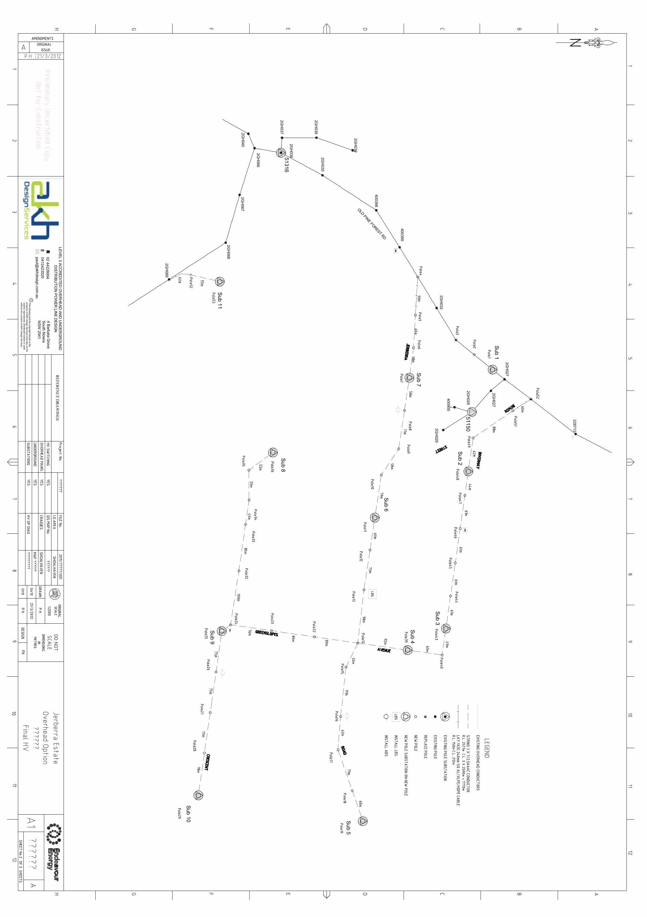
Overhead Option 1
The overall design has been based on a standard figure of allowed of 6.5kVA ADMD per lot, which is
the current requirement for subdivision lots in a coastal non gas area.
The design as set out on the attached plans for the overhead concept design option involves
connections points to the existing high voltage network in Pine Forest Road at pole 4 and pole 52.
These poles would to have high voltage overhead to underground terminations on them to allow for
the undercrossing of the adjacent transmission lines between the existing 11kV overhead network
and the proposed subdivision lots.
This short underground section would then transition back to overhead at pole 5 and poles 51 via 2
more high voltage overhead to underground terminations. The subdivisions would then be
reticulated in high voltage (11kV) open wire (bare conductor) on wood poles. All of the poles are to
be situated in the proposed road reserves in the standard Endeavour Energy footpath allotment for
overhead lines.
The low voltage is to be supplied via pole mounted substations of varying capacity dependant on the
number of customers to be supplied from each substation.
Endeavour Energy’s standards dictate that the area is one that requires a type of earthing called
separate earthing to be installed at each of the pole substation sites as there are insufficient final
customers and low voltage interconnections of the final low voltage network to establish a common
earthed system.
This separate earthing requires that certain restriction zones are placed around the buried high
voltage earths for each substation. The earths and restriction zones are designed to minimise the
transferred voltages to acceptable levels in the case of a fault in the transformer. The restriction
zones around the final HV earth locations are as below.
1. A 3m restriction zone, any building within this zone is to have 120/120/120 fire rating
2. A 4m restriction zone for metallic fences, buildings and pipes.
3. A 30m restriction zone, no swimming pools to be installed in this zone.
The existing soil resistivity is measured at each site and an earth grid configuration is determined. I
have applied an average resistance to all sites for this concept design, both for construction budget
allowance and earth restriction zone requirements.
The 30m restriction zone for swimming pools is shown on the overhead concept plan as a red outline
around each substation location.
The low voltage overhead reticulation is to be a combination of 150mm sq LV ABC and 95mm LV ABC
bundled conductor, to maintain the required voltage drop below the 5 volt standard as required.
Each of the lots has had supply made available from one of the pole mounted substations shown on
the plan. This supply point is indicated by the green line.

Showing a pole construction with bare
overhead high voltage and LV ABC bundled
low voltage on a wood pole in a semi rural
area
Showing a typical pole substation construction
with bare overhead high voltage and LV ABC
bundled low voltage on a wood pole in a semi
rural area

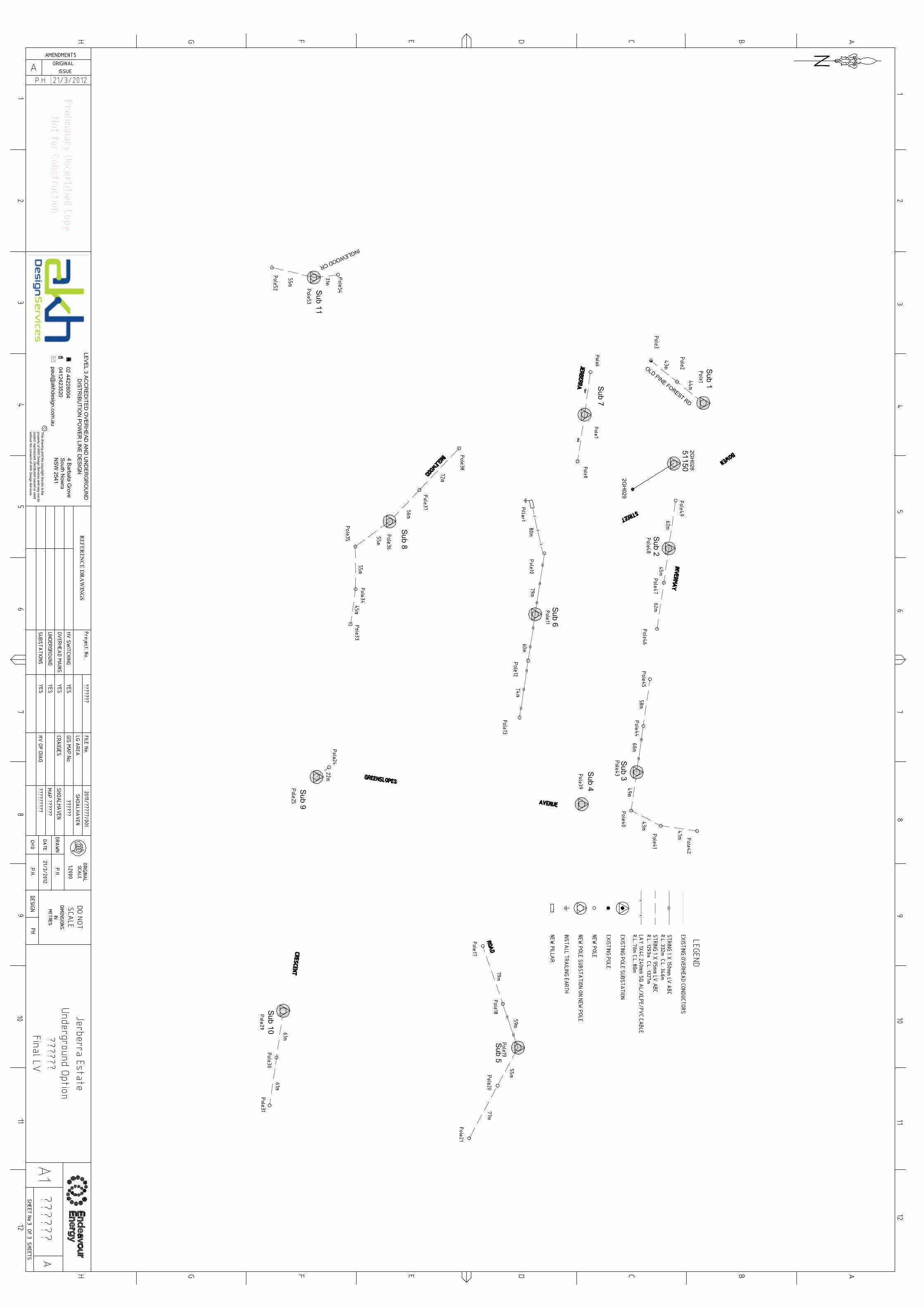
Underground Option 1
The overall design has been based on a standard figure of allowed of 6.5kVA ADMD per lot, which is
the current requirement for subdivision lots in a coastal non gas area.
The design as set out on the attached plans for the overhead concept design option involves
connections points to the existing high voltage network in Pine Forest Road at pole 1 and pole 27.
These poles would to have high voltage overhead to underground terminations on them to allow for
the undercrossing of the adjacent transmission lines between the existing 11kV overhead network
and the proposed subdivision lots.
The densest area of the subdivision would be reticulated underground whilst the sparser area would
remain reticulated in overhead.
Three 315kVA pad mounted substations would be installed on the lots as shown on the attached
concept plan. A high voltage ring feed would be established from pole 27 to Substation 1 then to
Substation 2 and then to substation 3 returning back to pole 1. This ensures that the subdivision is
not on a spur and allows for back feeding in times of emergency and maintenance.
The pad substations would need to be situated on lots with the relevant easements created around
them. The standard Easement size is 5.5m x 2.75m. The high and low voltage underground cables
would be installed in the standard Endeavour Energy footpath allotment for overhead lines.
The low voltage is to be supplied from the 315kVA padmount substations and pole mounted
substations of varying capacity dependant on the number of customers to be supplied from each
substation.
Endeavour Energy’s standards dictate that the area is one that requires a type of earthing called
separate earthing to be installed at each of the pad and pole substation sites as there are insufficient
final customers and low voltage interconnections of the final low voltage network to establish a
common earthed system.
This separate earthing requires that certain restriction zones are placed around the buried high
voltage earths for each substation. The earths and restriction zones are designed to minimise the
transferred voltages to acceptable levels in the case of a fault in the transformer. The restriction
zones around the final HV earth locations are as below.
1. A 3m restriction zone, any building within this zone is to have 120/120/120 fire rating
2. A 4m restriction zone for metallic fences, buildings and pipes.
3. A 30m restriction zone, no swimming pools to be installed in this zone.
The existing soil resistivity is measured at each site and an earth grid configuration is determined. I
have applied an average resistance to all sites for this concept design, both for construction budget
allowance and earth restriction zone requirements.
The 30m restriction zone for swimming pools is shown on the overhead concept plan as a red box
around the poles substations and as a blue box around each of the padmount substation locations.
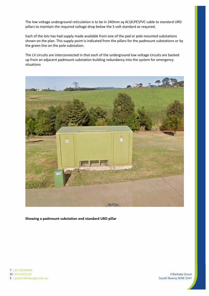
The low voltage underground reticulation is to be in 240mm sq AL\XLPE\PVC cable to standard URD
pillars to maintain the required voltage drop below the 5 volt standard as required.
Each of the lots has had supply made available from one of the pad or pole mounted substations
shown on the plan. This supply point is indicated from the pillars for the padmount substations or by
the green line on the pole substation.
The LV circuits are interconnected in that each of the underground low voltage circuits are backed
up from an adjacent padmount substation building redundancy into the system for emergency
situations
Showing a padmount substation and standard URD pillar

When making a comparison of the two options above. Overhead –v- Underground there are a
number of factors to be considered.
The overhead option will be the lower cost option of the two proposals; however the cost difference
may not be substantial.
Overhead power lines require clearing of 4m either side of the line for construction, whereas the
underground option requires clearing for trenching only.
The overhead option has all assets located in the road reserve whilst the underground option places
pad substations on the lots requiring easements to be created over these sites.
The actual installed earthing electrode requirements for pole mount substations are substantial less
than those for padmount substations; this is reflected both in final cost and the size of the final
restriction zone due to the final earth grid size.
Aesthetically overhead lines are less pleasing to the eye than the underground option where the
only visible assets are the pad substation and URD pillars
The final concern for the options is that of bushfires and how they impact on the assets. Overhead
assets are more susceptible to bushfire damage than underground assets, however in making that
statement a major fire will also cause substantial damage to the pad substations and URD pillars.
The final decision on the preferable option of supply and reticulation will need to be made taking all
of the above factors into consideration, including the particular requirements in relation to the land
approvals process, land clearing, Shoalhaven City Council requirements and the wishes of all
impacted parties.
Should you require any further information in regard to these matters please do not hesitate to call.
Yours Faithfully
Paul Hamilton