Embed Size (px)
Citation preview
LEva Brown - Re: Comparision between Fire Protection Regulations between Gemany and USA _____ ge
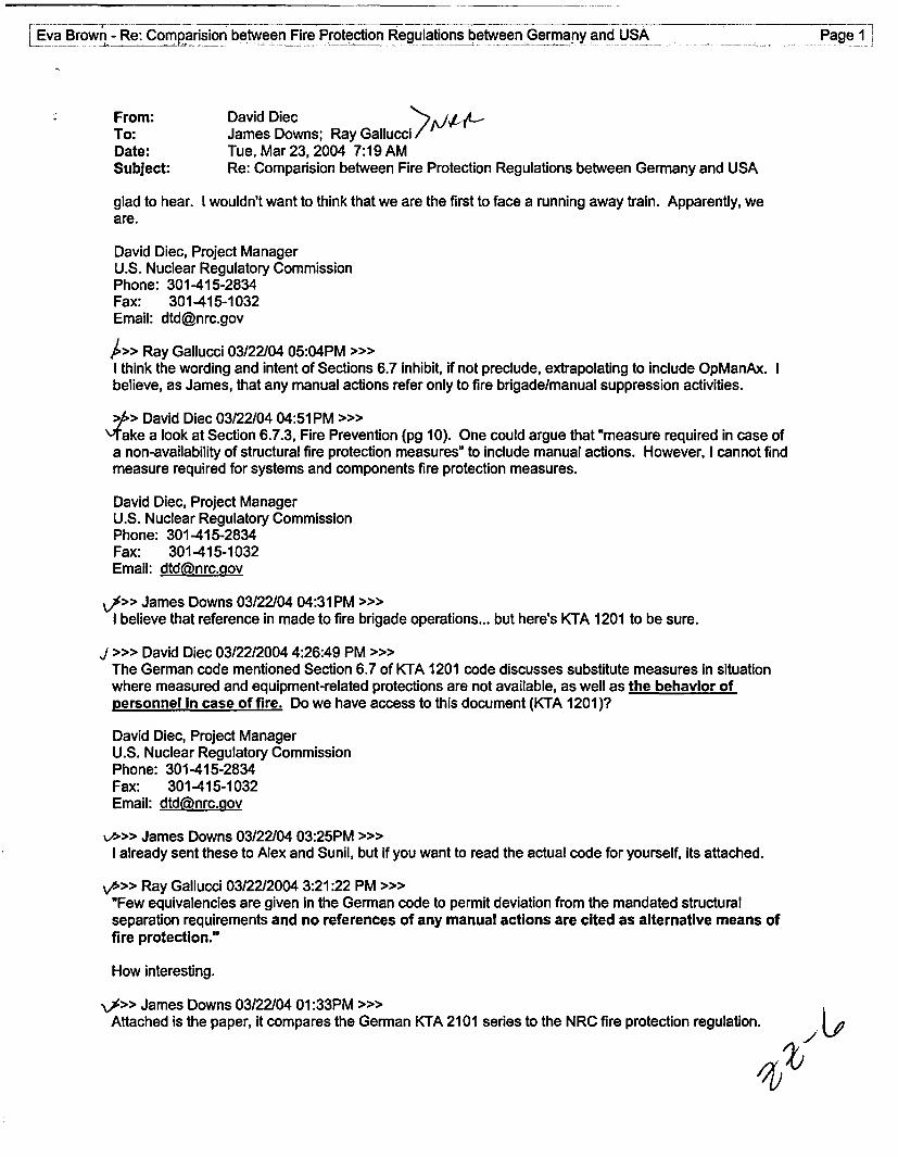
From: David DiecTo: James Downs; Ray GallucciDate: Tue, Mar 23, 2004 7:19 AMSubject: Re: Comparision between Fire Protection Regulations between Germany and USA
glad to hear. I wouldn't want to think that we are the first to face a running away train. Apparently, weare.
David Diec, Project ManagerU.S. Nuclear Regulatory CommissionPhone: 301-415-2834Fax: 301-415-1032Email: dtdenrc.gov
A>> Ray Gallucci 03/22/04 05:04PM >>>I think the wording and intent of Sections 6.7 inhibit, if not preclude, extrapolating to include OpManAx. Ibelieve, as James, that any manual actions refer only to fire brigade/manual suppression activities.
>&> David Diec 03/22/04 04:51 PM >>>\-Take a look at Section 6.7.3, Fire Prevention (pg 10). One could argue that "measure required in case ofa non-availability of structural fire protection measures" to include manual actions. However, I cannot findmeasure required for systems and components fire protection measures.
David Diec, Project ManagerU.S. Nuclear Regulatory CommissionPhone: 301-415-2834Fax: 301-415-1032Email: dtd(ainrc.gov
»>> James Downs 03/22/04 04:31 PM >>>I believe that reference in made to fire brigade operations... but here's KTA 1201 to be sure.
J >>> David Diec 03/22/2004 4:26:49 PM >>>The German code mentioned Section 6.7 of KTA 1201 code discusses substitute measures in situationwhere measured and equipment-related protections are not available, as well as the behavior ofpersonnel In case of fire. Do we have access to this document (KTA 1201)?
David Diec, Project ManagerU.S. Nuclear Regulatory CommissionPhone: 301-415-2834Fax: 301-415-1032Email: dtd(fnrc.aov
»>> James Downs 03/22/04 03:25PM >>>I already sent these to Alex and Sunil, but if you want to read the actual code for yourself, its attached.
\»>> Ray Gallucci 03/22/2004 3:21:22 PM >>>"Few equivalencies are given in the German code to permit deviation from the mandated structuralseparation requirements and no references of any manual actions are cited as alternative means offire protection."
How interesting.
\>> James Downs 03/22/04 01 :33PM >>>Attached is the paper, it compares the German KTA 2101 series to the NRC fire protection regulation.
vBrown - Re:_Comparision between Fire Protection Regulations between Germany and USA Page 2
-JD
A~>> Sunil Weerakkody 03/22/2004 1:12:34 PM >>>This is an outstaning product because it is written at the right level of detail with no editorial errors. I wasable to read the document and understand the high-level diffrences beween us and German regulationswithin about 10 minutes. Please share this with the rest of the section. Please send me an e-copybecause I want to share this with Suzie, Mike and John.
Sunil
CC: Eva Brown; Phil Qualls
Safety Standardsof theNuclear Safety Standards Commission (KTA)
KTA 2101.1 (12/2000)
Fire Protection in Nuclear Power PlantsPart 1: Basic Requirements
(Brandschutz in KernkraftwerkenTeil 1: GrundsAtze des Brandschutzes)
The previous version of this safetystandard was issued 12/85
If there is any doubt regarding the information contained in this translation, the German wording shall apply.
Editor:KTA-Geschaeftsstelle cto Bundesamt fuer Strahlenschutz (BfS)Willy-Brandt-Str. 5 * 38226 Salzgitter * GermanyTelephone +49-(0)1888/333-(0)1621 * Telefax +49-(0)1888/333-1625
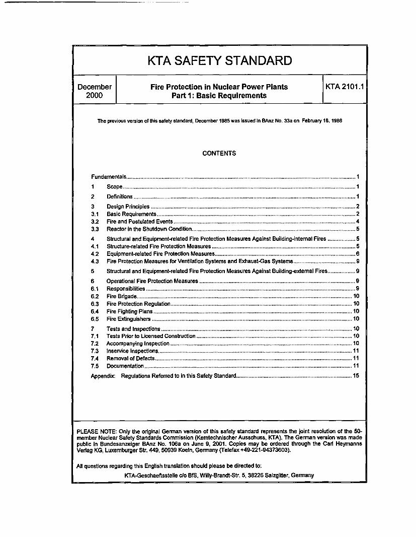
KTA SAFETY STANDARD
December Fire Protection in Nuclear Power Plants KTA 2101.12000 Part 1: Basic Requirements
The previous version of this safety standard, December 1985 was Issued in BAnz No. 33a on February 18, 1986
CONTENTS
Fundamentals.......................................................................................................................................................I
l1 Scope ................................................................... 1
2 Definitions ................................................................... 1
3 Design Principles ..................................................................23.1 Basic Requirements ................................................................... 23.2 Fire and Postulated Events ...................................................................43.3 Reactor in the Shutdown Condition ................................................................... 5
4 Structural and Equipment-related Fire Protection Measures Against Building-intemal Fires .................. 54.1 Structure-related Fire Protection Measures ................................................................... 54.2 Equipment-related Fire Protection Measures ................................................................... 64.3 Fire Protection Measures for Ventilation Systems and Exhaust-Gas Systems ........................................ 9
5 Structural and Equipment-related Fire Protection Measures Against Building-external Fires .................. 9
6 Operational Fire Protection Measures ................................................................... 96.1 Responsibilities .................................................................. 96.2 Fire Brigade .................................................................. 106.3 Fire Protection Regulation .................................................................. 106.4 Fire Fighting Plans .................................................................. 106.5 Fire Extinguishers .................................................................. 10
7 Tests and Inspections .................................................................. 107.1 Tests Prior to Licensed Construction .................................................................. 107.2 Accompanying Inspection .................................................................. 107.3 Inservice Inspections .................................................................. 117.4 Removal of Defects .................................................................. 117.5 Documentation .................................................................. 11
Appendix: Regulations Referred to in this Safety Standard .......................................... 15
PLEASE NOTE: Only the original German version of this safety standard represents the joint resolution of the 50-member Nuclear Safety Standards Commission (Kemtechnischer Ausschuss, KTA). The German version was madepublic in Bundesanzeiger BAnz No. 106a on June 9, 2001. Copies may be ordered through the Carl HeymannsVerlag KG, Luxemburger Str. 449, 50939 Koeln, Germany (Telefax +49-221-94373603).
All questions regarding this English translation should please be directed to:
KTA-Geschaeftsstelle clo BfS, Willy-Brandt-Str. 5, 38226 Salzgitter, Germany

Comments by the editor.
Taking into account the meaning and usage of auxiliary verbs in the German language, in this translation the following agree-ments are effective:
shall
shall basically
shall normally
should
may
indicates a mandatory requirement,
is used in the case of mandatory requirements to which specific exceptions (and only thosel) arepermitted. It is a requirement of the KTA that these exceptions - other than those in the case of shallnormally - are specified in the text of the safety standard,
indicates a requirement to which exceptions are allowed. However, the exceptions used shall besubstantiated during the licensing procedure,
indicates a recommendation or an example of good practice,
indicates an acceptable or permissible method within the scope of this safety standard.
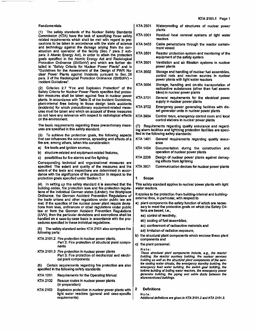
Fundamentals
(1) The safety standards of the Nuclear Safety StandardsCommission (KTA) have the task of specifying those safetyrelated requirements which shall be met with regard to pre-cautions to be taken in accordance with the state of scienceand technology against the damage arising from the con-struction and operation of the facility (Sec. 7 para. 2 sub-para. 3 Atomic Energy Act), in order to attain the protectiongoals specified in the Atomic Energy Act and RadiologicalProtection Ordinance (StrlSchV) and which are further de-tailed in 'Safety Criteria for Nuclear Power Plants and in'Guidelines for the Assessment of the Design of PWR Nu-clear Power Plants against Incidents pursuant to Sec. 28para. 3 of the Radiological Protection Ordinance (StrlSchV) -Incident Guidelines'.
(2) Criterion 2.7 'Fire and Explosion Protection' of theSafety Criteria for Nuclear Power Plants specifies that protec-tion measures shall be taken against fires in nuclear powerplants. In accordance with Table II of the Incident Guidelines,plant-internal fires belong to those design basis accidents(incidents) for which precautionary equipment-related meas-ures must be taken and which on account of these measuresdo not have any relevance with respect to radiological effectson the environment.
The basic requirements regarding these precautionary meas-ures are specified in this safety standard.
(3) To achieve the protection goals, the following aspectsthat can influences the occurrence, spreading and effects of afire are, among others, taken into consideration:a) fire loads and ignition sources,b) structure-related and equipment-related features,c) possibilities for fire alarms and fire fighting.Corresponding technical and organizational measures arespecified. The extent and quality of the measures and theextent of the tests and inspections are determined in accor-dance with the significance of fire protection in respect to theprotection goals specified under Section 1.
(4) In setting up this safety standard it is assumed that thebuilding codes, fire protection laws and fire protection regula-tions of the individual German states (LAnder), the WorkplaceOrdinance, the German Accident Prevention Regulations ofthe trade unions and other regulations under public law aremet. If the specifics of the nuclear power plant require devia-tions from laws, ordinances or other regulations under publiclaw or from the German Accident Prevention Regulations(UW), then the particular deviations and exemptions shall behandled on a case-by-case basis in accordance with the pro-cedures specified in these individual regulations.
(5) The safety standard series KTA 2101 also comprises thefollowing parts:
KTA 2101.2 Fire protection in nuclear power plants,Part 2: Fire protection of structural plant compo-nents
KTA 2101.3 Fire protection in nuclear power plantsPart 3: Fire protection of mechanical and electri-cal plant components
(6) Certain requirements regarding fire protection are alsospecified in the following safety standards:
KTA 1201 Requirements for the Operating Manual
KTA 2102 Rescue routes in nuclear power plants(in preparation)
KTA 2103 Explosion protection in nuclear power plants withlight water reactors (general and case-specificrequirements)
KTA 2101.1 Page 1
KTA 2501 Waterproofing of structures of nuclear powerplants
KTA 3301 Residual heat removal systems of light waterreactors
KTA 3403 Cable penetrations through the reactor contain-ment vessel
KTA 3501 Reactor protection system and monitoring of theequipment of the safety system
KTA 3601 Ventilation and air filtration systems in nuclearpower plants
KTA 3602 Storage and handling of nuclear fuel assemblies,control rods and neutron sources in nuclearpower plants with light water reactors
KTA 3604 Storage, handling and on-site transportation ofradioactive substances (other than fuel assem-blies) in nuclear power plants
KTA 3701 General requirements for the electrical powersupply in nuclear power plants
KTA 3702 Emergency power generating facilities with die-sel generator units in nuclear power plants
KTA 3904 Control room, emergency control room and localcontrol stations in nuclear power plants
(7) Requirements regarding quality assurance and regard-ing alarm facilities and lightning protection facilities are speci-fied in the following safety standards:
KTA 1401 General requirements regarding quality assur-ance
KTA 1404 Documentation during the construction andoperation of nuclear power plants
KTA 2206 Design of nuclear power plants against damag-ing effects from lightning
KTA 3901 Communication devices for nuclear power plants
I Scope
This safety standard applies to nuclear power plants with lightwater reactors.
It applies to the protection from building-internal and building-external fires, in particular, with respect toa) plant components the safety function of which are neces-
sary to meet the protection goals on which the Safety Cri-teria are based, i.e.,aa) control of reactivity,ab) cooling of fuel assemblies,ac) confinement of radioactive materials andad) limitation of radiation exposure,
b) the structural plant components which enclose these plantcomponents and
c) the plant personnel.Note:These structural plant components include, e.g., the reactorbuilding, the reactor auxiliary building, the nuclear servicesbuilding as well as the structural plant components of the serv-ke cooling water circuits, the emergency standby building, theemergency feed water building, the switch gear building, theturbine building of boiling water reactors, the emergency powergenerator building, the piping and cable ducts between theaforementioned buildings.
2 DefinitionsNote:Additional definitions are given in KTA 2101.2 and KTA 2101.3.
KTA 2101.1 Page 2
(1) Postulated EventA postulated event is an event on which the safety relateddesign of a nuclear power plant is based and which can setoff an entire event sequence.
(2) Structural and Equipment-related Fire Protection
Structural and equipment-related fire protection includes struc-ture-related and equipment-related fire protection measures thatprevent the occurrence and spreading of fires and that make itpossible for persons to escape and be rescued and that, also,make effective fire extinguishing activities possible.
a) Structure-related fire protection measures include meas-ures that result from requirements regarding the fire be-havior of structural materials and elements (e.g., walls,ceilings and isolating components), the location of firecompartments and arrangement of fire barriers, the loca-tion, arrangement and design of rescue routes as well asthe on-site access roads and areas for the fire brigade.
b) Equipment-related fire protection measures includeequipment and devices for the detection and fighting offires (fire protection equipment and devices), insofar asthese are permanently attached to the buildings, e.g., fireextinguishing devices, fire detection and alarm systems,heat and smoke removal systems. Equipment-related fireprotection measures also include measures taken with thegoal of preventing fires in mechanical and electrical plantcomponents. These are, e.g., measures resulting from thefire behavior of components and systems including theiroperating media.
(3) Operational Fire ProtectionOperational fire protection includes administrative measures(e.g. plant-internal fire brigade as well as instructions on thehandling of combustible operating and working media) as wellas mobile equipment for fire fighting (e.g., fire extinguishers)and for the escape and rescue of people(e.g., breathing appa-ratus).
Note:Operational tire protection measures are described in the plant-internal Fire Protection Regulation.
(4) Fire CompartmentsAfire compartment is the region of the building within its outerwalls and/or inside walls which are designed as fire wallsextending through all stories.
Note:Requirements for the design of fire walls are specified inKTA 2101.2.
(5) Fire Sub-compartmentsFire sub-compartments are subsections of fire compartmentsthat, on account of an increased fire hazard or for the protec-ton of equipment of the safety system are partitioned off bysufficiently fire resistant structural elements such that firespreading to, and having impermissible effects on, other sub-sections is prevented.
Note:Regarding the design requirements, see KTA 2101.2.
(6) Fire LoadThe fire load in the combustion energy (mass x specific com-bustion heat) of the combustible materials contained in , andbelonging to, the room.
(7) Fire Load DensityFire load density is the ratio of fire load to area of the room orof the group of rooms.
(8) Fire DamperFire dampers are active isolating devices against fire andsmoke that are triggered by the fire variables 'heat" or 'heatand smoke'.
(9) Rescue RouteA rescue route is a route that leads from any place in theroom if required via necessary corridors, protected corridorsand necessary stairways into the open or into a protectedarea; it serves both as escape route and, from the outside, asrescue route.
(10) Functional CapabilityFunctional capability is the ability of a system or of one ofits component parts (e.g., component, subsystem, train)including the necessary auxiliary, supply and power sys-tems to perform the prescribed tasks.
(11 ) Authorized ExpertAuthorized expert is an expert person or organization con-sulted in accordance with Sec. 20 Atomic Energy Act by thelicensing or supervisory authority.
(12) Safety SystemThe safety system comprises all equipment of a nuclear facil-ity that have the task of protecting the facility from an imper-missible loading and, when a design basis accident (incident)occurs, to keep the effects on the plant personnel, on thefacility and the environment within specified limits.
Note:Although equipment-related fire protection measures can be rele-vant to safety, they are not part of the safety system.
(13) Ignition SourcesIgnition sources are the permanently or temporarily availablepossibilities in an area of the plant which could release theamount of ignition energy required to ignite the availablecombustible material.
(14) Random FailureThe random failure is a failure which occurs statistically inde-pendently of failures of other similar equipment.
(15) EncapsulationEncapsulation is a measure that is suitable to protect Individ-ual equipment or combustible materials such that, in the caseof fire within or outside of the encapsulation, they will notbecome part of the fire scenario.
(16) Protected AreaA protected area is an area that is protected against the dan-gerous events that are at the root of the escape or of therescue mission.
3 Design Principles
3.1 Basic Requirements
3.1.1 General
(1) Measures for the protection from fires and the subse-quent effects shall be taken In nuclear power plants. Thesemeasures shall ensure that the protection goals specifiedunder Section 1 are achieved.
(2) A minimization of fire loads shall be taken into account inspecifying, both, the fire protection measures and the fireprotection concept. Measures that are in correspondence withthe chosen fire protection concept as specified under Sec-tion 3.1.2.1 shall be taken for the fire protective separation orencapsulation of combustible materials, for minimizing thesmoke development as well as for preventing anticipatedignitions sources in the areas of open combustible materials.
(3) Its shall, basically, be assumed that the ignition of com-bustible materials is possible. An exception may be made inthe case of the events specified in Section 3.2.2, provided,plausibility considerations prove that the combustible materi-als cannot be ignited as a result of these events. An exceptionmay also be made if the combustible material is encapsulated
and it is proven that the encapsulation retain their functionalcapability during specified normal operation and during thepostulated design basis accidents (incidents) - including fire.
Note:This assumption, that combustible materials will ignite, serves tofind the maximum fire effect for determining the required fire re-sistance rating of the fire enclosures of fire compartments and firesub-compartments. It does not serve as boundary condition offire-sequence related incident analyses.
(4) Fires do not have to be assumed to occur in inertedareas, e.g., the inerted BWR containment vessel. The situa-ton during the non-inerted phases shall be taken into ac-count.
(5) Structure-related fire protection measures of the struc-tural and equipment-related fire protection, e.g. the creation offire compartments, fire sub-compartments and areas sepa-rated by structures that are at least fire resistant, shall begiven priority over equipment-related fire protection measures.Insofar as the above-mentioned structural measures cannotbe implemented to the extent that the necessary protection isensured in the case of fire, additional measures regarding thedetection of fires (e.g. installation of additional fire detectors)as well as the fighting of fires (e.g. installation of stationary fireextinguishing systems) shall be taken.
(6) If safety-related reasons call for additional requirementsregarding structural and equipment-related fire protectionmeasures, e.g., radiation protection requirements, then theirfire protection function shall be evaluated taking these addi-tional requirements into account.
(7) Structural and equipment-related fire protection meas-ures shall be designed such that a fire-related failure need notbe assumed in case of their required operation.
In the case of fire in combination with other events in accor-dance with Section 3.2, the extent to which the structural andequipment-related fire protection measures may be damagedas a result of these events shall be examined, and it shall bedetermined whether further measures are necessary.
(8) Equipment of the safety system necessary fora) shutting down the reactor,b) maintaining long-term subcriticality,c) removing residual heat,d) retaining radioactive substances (adherence to the plan-
ning limits In accordance with Sec. 28 para. 3 StrlSchV)
shall be protected such that they can carry out their safety-related tasks to the required extent even in the event of fire. Inthe case of redundant equipment of the safety system, it shallbasically be ensured that, in case of a fire in the area of oneredundancy, the other redundancies will retain their functionalcapability. A failure of several redundancies as well as thefailure of non-redundant equipment of the safety system in theevent of a fire is permissible, provided, the simultaneousoccurrence of a fire and the necessary safety-related opera-tion of the respective equipment of the safety system does nothave to be assumed.
Note:Whether or not it is required that the nuclear power plant Is shutdown after a fire-related failure of equipment of the safety systemLs not subject of this safety standard.
(9) The fire protection design of anchors and supports ofcomponents shall be in accordance with the correspondingrequirements of the components.
(10) The entirety of fire protection measures shall ensurethat, in the case of a fire, a random failure of a single measureof the structure-related fire protection is not relevant to safety.
Note:The basic measures required in this respect are specified in thissafety standard and are dealt with in detail In safety standards
KTA 2101.1 Page 3
KTA 2101.2 and KTA 2101.3. Accordingly, it is not required in thefire protection design to assume a random failure (single failure)of an individual fire protection measure.
Insofar as individual fire protection measures have specialsignificance with regard to protecting the equipment of thesafety system, their reliability shall be ensured by specialmeasures that shall be specified on a case-by-case basis.
Note:The special significance of individual fire protection measures andthe resulting reliability requirements may be determined on thebasis of probabilistic safety analyses. Special measures are, e.g.,expanded test requirements, stationary fire extinguishing systemsinstead of manual fire fighting or automatic instead of manual trig-gering of the fire extinguishing systems.
(11) With regard to a fire in combination with other events asspecified under Section 3.2, it is not required to assume therandom failure of an individual fire protection measure.
3.1.2 Fire Protection Concept
3.1.2.1 General
A fire protection concept shall be developed and documentedunder consideration of the rules and regulations mentioned inSection Fundamentals (e.g., VBG 30, MBO, ArbStattV) aswell as the requirements specified under Section 3.1.1. Thefire protection concept shall be developed for full power op-eration including the maintenance tasks. Deviations on ac-count of a shutdown reactor as well the starting up and shut-ting down time phases shall be taken into consideration.
All measures directed at achieving the protection goal shall bedescribed in the fire protection concept.
3.1.2.2 Further Particulars on the Fire Protection Concept
The nuclear power plant specific demands on fire protectionshall be incorporated in the fire protection concept. This In-cludes the safety related evaluation of the plant componentsaffected by the fire as well as of the fire protection require-ments specified in the following sections, e.g., with regard to areliable physical separation of redundancies and the designagainst earthquakes.
In the case of plant regions where Sections 3.2 requires thatfire shall be analyzed in conjunction with a postulated otherevent, then the additional requirements or additional influ-ences from this postulated event shall be specified.
Note:The signal cables of the instrumentation and control system maybe neglected when determining the potential ignition sources.
3.1.2.3 Investigation of Fire Effects
(1) If the safety related evaluation of the plant componentsaffected by fire make it necessary to perform a detailed analy-sis of the fire effects, then corresponding data shall be givenwith respect to these fire effects.
This data may be derived from suitable analytical or experi-mental proofs, or may be proven with the help of analogy orplausibility considerations.
Note:Refer to Sec. 3 KTA 2101.2.
(2) The following fire effects shall be considered:
a) heat development Inside of the fire room or area,b) heat development outside of the fire room or area,
c) development and spreading of smoke,d) pressure buildup inside of the fire room or area.
(3) The analysis of fire effects shall take, e.g., the followingparameters into account
KTA 2101.1 Page 4
a) fire loads (taking encapsulations into consideration) andignition sources,
b) spatial geometry and type of component, heat sinks andheat sources,
c) ventilation conditions,d) possibilities for fire alarms and fighting the fire under con-
sideration of the chronological sequence of the fire.
3.2 Fire and Postulated Events
3.2.1 Fire and Subsequent Event
(1) In the case of pressurized vessels and components aswell as of plant components where an inherent failure can beexcluded on account of the individual quality characteristics,or of the limitation of the type of failure, measures shall betaken either to prevent fires in the area of pressurized vesselsor components or to protect against the effects of fires; it may,alternatively, be demonstrated that in the event of fire thequality characteristics making it possible to exclude an [inher-ent] failure or to limit the type of failure are not adversely af-fected in an impermissible way.
Note:Such pressurized vessels and components are, in the case ofpressurized water reactors, e.g., reactor pressure vessel, steamgenerators, pressurizers, primary coolant pumps and accumula-tors, and in the case of nuclear power plants with boiling waterreactors the scram accumulator tanks.Corresponding plant components are, e.g., containment vessel,safety-related supports and associated structural plant compo-nents as well as the storage pool for used fuel assemblies.
With regard to the mentioned quality characteristics, this canpertain to, eg., stress limit usage. A limitation of the type of failureis given, e.g., in case of a basic safety design In accordance withRSK-Guidelines for Pressurized Water Reactors.
(2) In the case of pressurized vessels and components aswell as of plant components where an inherent failure cannotbe excluded, measures shall be taken either to prevent firesor to protect these pressurized vessels and components aswell as the plant components against the effects of fire. Alter-natively, measures may be taken to protect the equipment ofthe safety system against the simultaneous impact of a fireand of a consequential event resulting from the above-mentioned vessels, components and plant components onaccount of the fire.
3.2.2 Postulated Event and Consequential Fire
3.2.2.1 Earthquakes and Consequential Fire
(1) Inside structural plant components which, because oftheir safety-related significance, are designed against earth-quakes in accordance with KTA 2201.1, either the equipmentwhich, on losing integrity, would release combustible materi-als or the equipment which could cause ignition shall basicallyalso be designed to resist the effects of these events by se-lecting suitable materials and by an appropriate design.
Note:By implementing this requirement, a consequential fire due toearthquakes need not be assumed.The individual building parts shag be specified in the fire protec-tion concept
(2) If the equipment mentioned in para. 1 has not beencorrespondingly designed, then structural and equipment-related fire protection measures shall be provided which shallthemselves be designed to resist the effects of these eventsby the selection of suitable materials and mechanical design.In this case, the consequential fire shall be considered tooccur only after the earthquake has subsided.
Note:The individual fire protection measures shag be specified in thefire protection concept
(3) Insofar as the intensity, , of the presumed earthquakeis presumed to be less than or equal to 6 (on the MSK scale),it may be assumed that the structure-related and operationalfire protection measures will remain available even withoutspecial design measures.
3.2.2.2 Plant-internal Events and Consequential Fire
(1) The structure-related fire protection measures shall becarried out such that in the case of redundant equipment ofthe safety system any fire assumed to be a direct conse-quence of a plant-internal event will, basically, remain re-stricted to a single redundancy of this equipment. The failureof several redundancies as well as the failure of non-redundant equipment of the safety system is permissible insubstantiated exceptional cases, provided, the simultaneousoccurrence of a fire and the required safety-related operationof the respective equipment of the safety system does nothave to be assumed.
(2) In this context, the occurrence of a fire does not have tobe assumed for design basis accidents (incidents) involvingthe release of steam.
3.2.3 Postulated Event and an Unrelated Fire
Note:This section does not in any way affect the requirements specifiedunder Section 3.2.2.1.
(1) The simultaneous occurrence of an external event(earthquake or high water) or of an internal event and anunrelated fire, basically, does not have to be assumed be-cause the occurrence probabilities of such combinations aresufficiently small. However, if the combination of the hundred-yearly high water with a fire and restricted access conditionsof the plant has a safety-related significance, then this combi-nation shall be postulated.
(2) An unrelated fire shall, basically, not be excluded afteran earthquake or high water. In this case, however, only thosestructure-related or operational fire protection measures needto be available or be made available which are necessary tofor retaining the functional capability of the equipment speci-fied under Section 3.1.1 para. 8.
Note:In his case it is permissible to also fall back on help external tothe nuclear power pant site.
The following shall apply to this equipment:
a) With respect to minor earthquakes up to the inspectionlevel In accordance with KTA 2201.6, the availability of thestructure-related fire protection measures shall, basically,be maintained by engineering means (e.g., by adhering tothe pipe routing provisions approved In the licensing pro-cedure).
b) Insofar as the intensity, , of the above-mentioned earth-quakes are presumed to be smaller than or equal to 6 (onthe MSK scale), it may be assumed that the structure-related and operational fire protection measures will re-main available even without special design measures.
c) The structure-related and operational fire protectionmeasures need not be designed against larger earth-quakes up to the design-basis earthquake, provided, it isensured that after the occurrence of a design-basis earth-quake the possibly failed structure-related or operationalfire protection measures can be made available or be re-placed by suitable measures immediately after the event.
KTA 2101.1 Page 5
Note:'Immediately after the event' refers to a maximum time period ofone week.
Regardless of these requirements, in case of post-earthquaketasks with special fire hazards (e.g. heat intensive tasks)additional administrative fire protection measures (e.g. mobilefire pumps, fire guard) shall be provided.
3.3 Reactor in the Shutdown Condition
(1) The structure-related and operational fire protectionmeasures shall be reviewed with regard to whether or not theyshall be modified or supplemented in view of the modifiedoperating conditions during this plant condition (shutdownreactor, possible additional combustible materials or a changeof their location, possible ignition sources during repair work,additional personnel during inspection, servicing and repairwork).
(2) The additional fire loads usually present during the revi-sion phase shall be taken into consideration in selecting thestructure-related fire protection measures.
(3) The fire protection concept shall reflect the changedconditions regarding fire protection, shall describe the basicmeasures and shall indicate that additional measures maybecome necessary and that these measures, then, shall bespecified in each individual case.
Note:These measures include, in particular, operational fire protectionmeasures such as fire guard, the availability of additional fire ex-tinguishers and restrictions on bringing in additional fire loads. Inthis regard, also refer to Section 4.2 5.4.
4 Structural and Equipment-related Fire ProtectionMeasures Against Building-internal Fires
4.1 Structure-related Fire Protection Measures
4.1.1 Fire Load
(1) The fire load shall be kept as small as possible.
(2) Non-combustible construction materials in accordancewith Class A DIN 4102-1 shall basically be used. If combusti-ble materials are used it shall be demonstrated that suitablenon-combustible materials are not available.
(3) Combustible construction materials shall, basically, beflame retardant in accordance with Class B 1 DIN 4102-1.With regard to smoke development, they shall, basically,comply with the requirements in accordance with Class A 2DIN 4102-1. They shall be taken into consideration in deter-mining the fire loads.
Note:Specifications regarding the requirements for the fire behavior ofdecontaminable coatings and cold-water insulations are dealt withIn Sec. 7.3 pars. 3 KTA 2101.2 and Sec. 3.12 KTA 2101.3.
(4) Fixed flooring and decontaminable coatings may beignored as fire load, provided, it is proven that they wouldcontribute only negligible amounts to the fire scenario onaccount of their type, amount and condition of Installation.Fire protection coatings (e.g. intumescent coatings) may beignored as fire load, provided, it proven that, under considera-tion of the fire exposure from unprotected fire loads, theywould contribute nothing or only negligible amounts to the firescenario.
4.1.2 Encapsulation
(1) Encapsulations are permissible. These can be in theform of sheet metal jackets, fire protection plates or intumes-cent coatings.
(2) It shall be shown that the individual technical encapsula-tion measures are suitable with regard to the objective of thefire protection concept. This shall take into consideration thetype of combustible material to be protected, the installation,amount and distribution of the unprotected and other fireloads as well as the operating conditions to be observed and,in this connection, the general restrictions to be taken intoconsideration.
4.1.3 Fire Protective SeparationNote:Further details regarding fire protective separation are containedin KTA 2101.2.The formal requirements to be taken Into consideration when de-viating fhom regulations under public law are described in SectionFundamentals pare. 4.
(1) The individual structures in a nuclear power plant shallbe separated from one another either by sufficient distancesor by sufficiently fire resistant structural elements.
(2) The structural components shall basically be subdividedinto fire compartments taking the requirements Imposed bysystems engineering into consideration.
(3) The individual fire compartments shall be subdividedbasically into single-story fire sub-compartments under con-sideration of the fire load densities, the requirements withregard to system engineering and operation as well as theredundancies and rescue routes.
In case systems engineering requires a configuration of multi-story fire sub-compartments, then additional fire protectionmeasures shall be taken in order to achieve an equivalentprotection condition.
(4) The walls, ceilings and isolating components of fire sub-compartments shall have a sufficient resistance to fire.
(5) If the requirements of systems engineering lead to therequirement that the fire compartments must be larger than inaccordance with the building code or that the fire protectionrequirements of individual structural elements cannot becompletely met, then other suitable measures (e.g., creationof fire sub-compartments, encapsulation of fire loads, object-related fire alarms, stationary fire extinguishing systems) shallbe taken if these measures help to achieve the protectivegoals.
Note:Examples of this are: reactor building, reactor auxiliary building,turbine building, reactor service building.
(6) Insofar as pressure equalization openings are necessaryfor the control of design basis accidents (incidents), openingsin structural partitions are permissible, provided, they complywith fire protection requirements.
In this case, it is permissible that the openings are closedautomatically only in case of fire or that the closures areopened only in case of pressure equalization. The corre-sponding protection measures shall be specified in each indi-vidual case.
(7) In the case of necessary openings in outer walls, it shallbe ensured that the spread of fire from one fire compartmentto another is prevented. The corresponding protection meas-ures shall be specified in each individual case.
(8) Ventilation ducts and pipes which pass through thepartitions between fire compartments or fire sub-compartments shall be designed such that a fire cannotspread from one area to another. The fire resistance rating ofthe special elements employed for this purpose shall complywith the fire protection requirements for the partitioning struc-tural elements.
KTA 2101.1 Page 6
(9) Penetrations for cables and pipes through fire walls orthrough separating walls or ceilings of other fire sub-sectionsshall be provided with fire barriers. The fire resistance capa-bility of these fire barriers shall be equal to that of thepartitioning structural elements.
After working on the fire barriers of cables and pipes, it shallbe ensured that these fire barriers either remain in functioningorder or are again returned to this state.
(10) In the case of ventilated pipe and cable ducts that aresectionalized for fire protection purposes, the ventilationopenings shall be provided with fire dampers or fire protectionisolating components. Their fire resistance capability shallcorrespond to that of the partitioning structural elements.
(11) Redundant equipment of the safety system shall beprotected either by sufficiently fire resistant structuralelements (at least F 90-A in accordance with DIN 4102-2) orby physical separation such that a failure of several redun-dancies as a result of a fire can be excluded under theboundary conditions mentioned in Section 3.1.1 para. 8. Inwell founded exceptional cases this same protection goal maybe achieved by encapsulation (ensuring continuation of func-tionality) or by cable systems with ensured continuation offunctionality or by fire extinguishing systems or by combina-tion of these measures.
(12) Insofar as physicals separation is the only suitable fireprotection measure in accordance with Section 3.1.1 to en-sure necessary functional capability of the equipment of thesafety system in case of fire, thena) the stability of the ceilings and walls used for this purpose
as well asb) the functional capability of the fire protection isolating
components and fire barriers required in each individualcase
shall be demonstrated under consideration of the require-ments resulting from the analyses in accordance with Sec-tions 3.2.1, 3.2.2 and 3.2.3.
Note:It shall be assumed that the fire protection closures and fire bari-ers are in specified normal condition at the point in time of theaforementioned loading.
(13) In the case of substantial fire loads, e.g., large assemblyof cables In cable rooms, fuel storage compartments for theemergency power diesels, separate sufficiently fire resistantareas (at least F 90-A in accordance with DIN 4102-2) shallnormally be provided.
4.1.4 Areas and Fire Access Routes for the Fire Brigade
It shall be ensured that, with regard to the preparation for anintervention by the fire brigade, the required free movementareas for the fire engines, for the positioning of equipment andfor the preparation of rescue and fire fighting operations includ-ing the necessary fire access routes and fire entries are avail-able. DIN 14 090 shall basically be applied in this connection.
Note:Exceptions are dealt with in Sec. 4 KTA 2101.2.
Fire access routes for the fire brigade and rescue routes shallbe kept clear of obstructions.
Note:In particular, the rescue routes provided in accordance withKTA 2102 are considered as fire access routes for the fire brigade.
4.2 Equipment-related Fire Protection Measures
4.2.1 Fire Load
(1) Basically, only non-combustible operating media shallnormally be used. Exceptions are permissible for hydraulicand lubrication fluids as well as for other combustible materi-
als, provided, they are unavoidable for operational reasons. Itis recommended to use flame retardant hydraulic fluids.
Note:Corresponding details are specified in safety standardKTA 2101.3.
(2) Basically, only non-combustible materials shall be used.However, the use of combustible materials is permissible,provided, they are unavoidable from a design standpoint, e.g.,insulating materials around cold piping, decontaminablecoatings. The combustible materials shall basically corre-spond to Class B 1 DIN 4102-1. The use of combustible mate-rials required from a design standpoint is permissible withoutcertification, provided, only a negligible increase of the firehazard is incurred, e.g., internal coatings, underground-routedcables outside of buildings, seals and small parts.
Note:Under comparable conditions, materials can be classified ascombustible and non-combustible in accordance with DIN 4102-1.
(3) Negligible fire loads (e.g., flange gaskets, identificationtags, coatings of mechanical components) may be ignored.The determined fire loads may be ignored in the fire protec-tion design, provided,a) they are stored inside the components in a condition
where an ignition can - even under an external fire influ-ence - be precluded, or
b) the components - depending on the external or internalignition possibilities - are designed against possible load-ings during specified normal operation and retain theirfunctional capability during the postulated design basisaccidents (including fire), or
c) it is proven that under consideration of effects of the firethe combustible materials will not be set free.
(4) In the containment vessel of light water reactors, onlysuch cables shall basically be used that counteract rapid firespreading and that do not release corrosive gases in the caseof fire (e.g., special halogen-free cables).
Note:Requirements for such cables are specified in safety standardKTA 2101.3.
Exceptions are permissible where special electrical properties(e.g. measuring cables) or special mechanical properties (e.g.flexibility) are required. In case of an amassing of cables in-side the containment vessel that do not have the above men-tioned characteristics, then the protection goal shall beachieved by other suitable means.
4.2.2 Fire Alarm
(1) A fire detection and alarm system with automatic firedetectors shall be provided. The extent and arrangement ofthe automatic fire detectors depend on the following aspects:
a) fire load density,
b) arrangement of the combustible materials in the rooms,
c) burning behavior (spreading of flames, smoke develop-ment) of the combustible materials,
d) safety relevance of the components or systems,
e) personnel protection (ensuring escape and rescue),f) criteria for triggering fire dampers, fire protection isolating
components,g) criteria for triggering stationary fire extinguishing systems.
Note:Cornesponding details are specified in safety standardKTA 2101.3.
(2) The fire detection and alarm system shall normally bedesigned to ensure a sufficiently exact location of a fire In-cluding the identification at the fire alarm boards.
KTA 2101.1 Page 7
Note:Details are specified in safety standard KTA 2101.3.
(3) Interference levels due to, e.g., soiling of the automaticfire detectors shall normally be automatically compensatedfor.
(4) Erroneous alarms shall not trigger impermissible controlsignals. This pertains, in particular, to earthquakes and plant-internal design basis accidents (incidents).
(5) It shall be possible, depending on the fire protectionconcept, to control the fire protection equipment from the firealarm boards.
(6) Insofar as fire fighting measures are necessary in thecase of fire to ensure the required functional capability ofequipment of the safety system, it shall be demonstrated thatthe fire detection and alarm system retains its functional ca-pability even under consideration of the requirements result-ing from the analyses in accordance with Sections 3.2.1, 3.2.2and 3.2.3.
(7) The displays and controls necessary for the head of fireactions shall be installed in the control room or in a controlroom annex. At least one group alarm of the fire detection andalarm system shall be installed in plain view of the controlroom personnel.
(8) Overview plans indicating the alarm zones, the accessroutes and the locations of fire fighting equipment as well asinstructions regarding proper behavior in the case of firealarms and of malfunctions of the fire detection and alarmsystems shall be provided in the direct vicinity of the controlroom.
Note:Computer printouts are permitted, provided a documentation isavailable in the direct vicinity of the control room.
4.2.3 Fire Water Supply
(1) A sufficiently large fire water system shall be provided.
Note:Corresponding details are specified In safety standardKTA 2101.3.
Either a natural source of water such as rivers, streams,lakes, or an artificial source of water such as a fire water pondin accordance with DIN 14 210, a fire water well in accor-dance with DIN 14 220, or a fire water tank in accordance withDIN 14 230 with a sufficient quantity of water shall be avail-able as fire water supply. The water may be fed into the firewater system by means of fire pumps or high-level storagetanks.
(2) A fire water ring line system shall be installed on the sitein the vicinity of the buildings and shall be kept permanentlyunder pressure. It shall be possible to subdivide the ring linesystem such that, even in case of a break at any point, basi-cally all structural plant components specified in Section 1 canbe supplied with sufficient amounts of fire water, the excep-tions are the cooling-water intake and outfall structures.
(3) The underfloor hydrants in accordance with DIN 3221and the pillar hydrants in accordance with DIN 3221 shall alsobe connected to the fire water ring line system. Hydrants shallbe located near the entrances to buildings and, outside on thesite, in close vicinity of the buildings.
Note:The hydrants may, alternatively, be supplied fromn a dedicatedseparate system, provided, its design is equivalent to that of therng line system.
(4) All buildings accommodating equipment of the safetysystem shall basically be provided with wet rising mains. Itshall be ensured that, in the case of loss of integrity of suchmains, the functional capability of the equipment of the safety
system is retained to the extent that they can still fulfill theirspecified functions in the case of design basis accidents (inci-dents). Wall hydrants in accordance with DIN 14 46-1,DIN 14 461-6, DIN EN 671-1 and DIN EN 671-2 shall be lo-cated such that all possible fire sources can be reached bythe fire water jet.
(5) The fire pumps shall be redundant and shall beequipped with a protected or independent power supply; apressurizer system shall be provided. Fire pumps or high-levelstorage tanks shall be spatially separated or protected suchthat an event causing the failure of an individual fire pump,high-level storage tank or supply line to the ring line systemdoes not lead to a failure of supplying the required amount ofwater in case of required operation.
(6) The fire pumps or high-level storage tanks shall beswitched on line automatically if there Is a pressure drop inthe fire water system. In addition, it shall be possible to moni-tor and operate them from the control room. It shall normallybe only possible to switch off the pumps by manual action.
(7) It shall be possible to reopen the containment vesselpenetration valves of the fire water supply after their closurewas triggered by the reactor protection system.
4.2.4 Fire Extinguishing Systems
(1) Stationary fire extinguishing systems shall be providedfor in the case of large unprotected fire loads either from eas-ily combustible operating media or that are seen in a combi-nation with, e.g.,a) difficult access (e.g., cable duct, rooms with a high local
dose rate) orb) rapid fire propagation or
c) inadequate smoke or heat removal.
(2) Fire extinguishing systems shall be designed such that,in case of malfunctions and operating errors upon requiredoperation, the functional capability of the safety system isretained to the extent that it can perform its specified normalfunction in the case of design basis accidents (incidents). If, Incase of fire, the necessary functional capability of the equip-ment of the safety system is ensured exclusively by means offire extinguishing systems, then the functional capability ofthese fire extinguishing systems shall be demonstrated underconsideration of the conditions resulting from the analysesspecified under Sections 3.2.1, 3.2.2 and 3.2.3. In selectingthe fire extinguishing agent, care shall be taken to ensure thatthe equipment of the safety system to be protected is notrendered Inoperable as a result of the effects cause by the fireextinguishing agent.
(3) Insofar as stationary fire extinguishing systems are pro-vided as exclusive fire protection of the equipment of thesafety system, their reliability shall be ensured in accordancewith Section 3.1.1 by means of special measures to be speci-fied in each individual case.
(4) Stationary fire extinguishing systems shall basically beactivated automatically. Remotely controlled or on-site manu-ally actuated fire extinguishing systems are permissible, pro-vided, the possible fire effects up to the moment when thesefire extinguishing systems become effective can be kept un-der control.
Note:In the assessment of an automatic activation due considerationshall be given to the disadvantages of an erroneous activation,e.g., the failure of safely-related equipment, an erroneous activa-tion in the case of steam leakage, contamination of the fire waterand the effects of the fire extinguishing agent on the parts withhigh surface temperatures.
(5) If cables with an improved behavior in case of fire areused, e.g., special halogen-free cables or cables and cable
KrA 2101.1 Page 8
ducts with a fire protection coating (e.g. intumescent coat-ings), then it shall be demonstrated in the individual casewhether stationary fire extinguishing systems are necessaryor not.
Note:Also refer to Section 4.2.1 para. 4.
(6) Insofar as large quantities of water must be expectedduring the fire extinguishing procedure, e.g. in the case ofspray water suppression systems, possibilities for removingthe water, if necessary by means of mobile pumps, shall beavailable.
Fire water from the controlled area shall basically only bedischarged under controlled conditions. Exceptions are per-missible in the case of temporarily installed controlled areas,provided, the release of radioactive substances is not to beexpected.
(7) In the case of remotely controlled fire extinguishing sys-tems, the electrical triggering devices shall be installed eitherin the control room or in a control room annex.
4.2.5 Heat and Smoke Removal
4.2.5.1 General Requirements
(1) The ventilation systems may be used In case of a fire forthe mechanical smoke removal. When used for this purpose,the requirements to be specified for the temperature andpressure resistance of individual structural elements of theventilation systems may be specified under consideration ofthe mixture temperature attained in the ventilation pipes.
(2) If ventilation systems are planned to be used for heatand smoke removal, they shall be arranged such that smokeis not carried into the air supply.
(3) If mechanical heat and smoke removal equipment isused, it shall be ensured that this does not endanger personsnor any equipment of the safety system in other areas sepa-rated by fire protection measures from the area affected bythe fire.
(4) The measures to be taken in the individual case shall bespecified depending on the local conditions. Specific aspectsare:a) location of the room,b) the possibilities for air supply and air exhaust with the
ventilation system,c) objective of the smoke removal, e.g., ensuring mobile fire
fighting activities,d) restrictions regarding radiation protection, e.g., small air
supply and exhaust volume.
4.2.5.2 Heat and Smoke Removal from Structural PlantComponents Outside the Controlled Area
Heat and smoke removal systems shall be provided for thosestructural plant components specified in Section 1 that areoutside the controlled area unless it is ensured through otherfire protection measures that the heat and smoke removal isnot required for fire fighting. The available ventilation systemsmay be used for this purpose if they are appropriately de-signed and constructed.
4.2.5.3 Heat and Smoke Removal from Structural PlantComponents Inside the Controlled Area
(1) Smoke removal from the structural plant components ofthe controlled area is allowed to the extent required for firefighting and to rescue people. This shall basically carried outonly via the paths designated for the discharge of radioactivesubstances during specified normal operation.
Note:Depending on its location and duration, a fire can lead to circum-stances which must be classified either as abnormal operation oras a design basis accident (incident). A large-volume smoke re-moval is not possible from the Interior of the reactor building be-cause of the requirements regarding control and mitigation of aloss-of coolant accident.
Nuclide-specific measurements are not necessary since the envi-ronmental radiological exposure can be determined to sufficientaccuracy by other ways after the smoke has been removed.
(2) The heat and smoke removal via paths other than thedischarge paths for specified normal operation (e.g. via buiit-in dampers for the heat and smoke removal to the outside) Ispermitted from those sub-areas of the controlled area whichare separated in terms of fire protection and ventilation andwhich have been demonstrated to be radiologically irrelevant(e.g. necessary stairways); it is also permitted from the turbinebuilding (BWR).
(3) If the ventilation system is provided with air filtrationunits, it shall be ensured that, e.g, temperature, pressure, fireproducts or fire extinguishing agents do not have impermissi-bly adverse effects on the air filtration units.
Note:For example, under consideration of the expected environmentalradiological exposure, provisions can be made to bypass the filterunit.
(4) It shall be ensured that the removal of cold smoke aftera fire will be possible. This smoke may also be removed viathe existing ventilation system. Prior to the discharge of coldsmoke, a sample shall be taken and analyzed with respect toits content of radioactive substances
4.2.5.4 Keeping Rescue Routes Free of Smoke
(1) In the case of plant-intemal fires, protected corridors andnecessary stairways shall be kept free of smoke to such ex-tent that there is enough air for breathing and adequate visi-bility for orientation.
Note:Inside the reactor building interior, It may become necessary thatthe ventilation of the rescue routes must be switched off for rea-sons of radiological protection and that as a result the rescueroutes will not be entirely dear of smoke.
(2) Necessary stairways may be kept dear of smoke bynatural convection or by mechanical equipment Mechanicalequipment shall be provided for the protected corridors. Out-side of the rescue routes specified under para. 1, the air sup-ply lines to these rescue routes shall basically be of a fireresistant design. The air supply lines should have the samefire resistance rating as those building elements enclosing theprotected rescue routes. Air exhaust lines shall normally havethe same fire rating as the corresponding air supply lines.
Regarding the reactor building interior, equipment-relatedspecial features shall be taken into consideration.
Note:Details regarding fire rating are specified In safety standardKTA 2101.2.The installation of air supply and exhaust openings for naturalconvection may be complicated by other requirements, e.g. re-garding radiological protection or plant security.In general, natural convection Is only effective in stairway sec-tions above ground level.
(3) Technical measures shall normally be provided withregard to airlock annexes in the reactor building interior andthe stairways connected to these annexes such that, underconditions prevailing during major inspections (e.g. unlockedand open airlock doors of personnel airlocks), a sufficientventilation of these annexes and stairways is achieved for theduration required for the escape from the containment vessel.
KTA2101.1 PageD9
Restrictions arising from radiological protection considerationsshall be taken into consideration. In the case of a fire, theentire air supply shall normally be fed directly into the above-mentioned annexes and stairways.
4.2.6 Displays and Controls of Other Equipment Relevantto Fire Protection
The remote controls and the check-back and malfunctiondisplays of other equipment relevant to fire protection, e.g.,position detectors of the fire dampers, shall be installed in thecontrol room or in a control room annex. At least one groupalarm of the fire alarm system shall be installed in the controlroom or control room annex and to the required extent in theremote shutdown station. At least one optical and acousticalcollective alarm shall be located in the control room.
Note:Details regarding displays and controls of the other equipment arespecified in Sec. 9 KTA 2101.3.
4.3 Fire Protection Measures for Ventilation Systems andExhaust-Gas Systems
4.3.1 General Requirements for Ventilation Systems
(1) The ventilation systems shall be designed such that theyshall basically be designed to be in conformity with the build-ing supervision guidelines.
Exceptions are permitted as specified under Section Funda-mentals para. 4 for the following reasons:a) radiation protection (e.g., maintaining subatmospheric
pressures during design basis accidents (incidents)),b) physical separation of redundancies with the goal of being
able to operate the unaffected redundancy,c) prevention of the spreading of smoke,d) possibilities for the removal of smoke,e) keeping the protected corridors and necessary stairways
free from smoke.
(2) In the event of fire, a spreading of smoke and radioactiv-ity into unaffected areas shall be prevented as long as possi-ble.
Note:This may be achieved, e.g., by avoiding air circulation operationor by proper control of the fire dampers.
(3) In the case of redundant equipment of the safety systemwhere the redundancies are separated from each other bystructure-related fire protection measures, the associatedventilation systems shall be arranged, designed and con-structed such that a fire of one redundancy does not affect thefunctionality of other redundancies.
(4) The ventilation of the control room and the emergencycontrol center and their annexes shall be ensured even in thecase of a fire in directly adjacent fire compartments. This doesnot apply to a fire in the ventilation system itself.
(5) It is recommended that the ventilation equipment pro-vided to ensure the containment closure (quick-closing valveson the containment vessel) be arranged or protected suchthat the ciosing of one valve per ventilation duct is possibleeven in the case of fire.
Note:In this case, i does not have to be assumed that fires break outsimultaneously inside and outside of the containment vessel.
(6) The fans in those ventilation systems the function ofwhich shall be ensured in the case of fire shall be providedwith a reliable power supply. An auxiliary power supply inaccordance with safety standard KTA3701 may be consid-ered as sufficiently reliable. The fans do not have to be re-dundant for fire protection reasons.
(7) Superordinate safety related requirements forbid that theaccident filtration systems controlled by the reactor protectionsystem be blocked off by fire dampers. In such cases, aspreading of fire Into other fire compartments shall be pre-vented by the type and routing of the ducts.
4.3.2 Fire Dampers
(1) In cases where spreading of smoke is not permissible,thermal activation of the fire dampers shall be supplementedby other possibilities, e.g., activation by a fire detection andalarm system, manual activation onsite outside of the fireroom or area, remote activation from the control room. In thisrespect, effects from erroneous activations shall be taken intoaccount.
(2) The controls of those fire dampers which, for reasons ofsafety, may only be activated in the case of fire but shall oth-erwise remain in the 'open' position, shall be designed suchthat their erroneous activation either does not have to beassumed or that, in individual cases, they can be reopenedwithin a predetermined time period.
Note:Corresponding details are specified in safety standardKTA 2101.3.
(3) Position indicators shall normally be located in the controlroom area. At least one group alarm shall be located in plainview of the control room personnel.
4.3.3 Activated Charcoal FiltersSuitable measures shall be taken to prevent the occurrenceand spreading of fires of activated charcoal in the filters of theventilation and exhaust gas systems and to contain such fires.
Note:Corresponding details are specified in safety standardsKTA 2101.2 and KTA 2101.3.
5 Structural and Equipment-related Fire ProtectionMeasures Against Building-external Fires
(1) The fire loads stored as specified on the nuciear powerplant site outside of buildings shall be separated from theindividual buildings of the nuciear power plant by a sufficientdistance or by sufficiently fire-resistant structural elements.
(2) The penetration of smoke and hot fire fumes into theindividual buildings via the ventilation systems shall basicallybe prevented (cf. Construction Supervision Guideline 'Ven-tilation Systems"). The prevention of the penetration of smokeand hot fire gases does not have to be proven In the case ofbuilding areas which do not contain equipment of the safetysystem and which do not have to be occupied by personnelfor safety reasons.
(3) Further measures related to the combination of eventsas specified under Sections 3.2.1, 3.2.2 and 3.2.3 may bedisregarded, provided, the requirements in accordance withSec. 19.1 RSK Guidelines for PWR are met concerning fuelfires in the case of an aircraft crash.
6 Operational Fire Protection Measures
6.1 Responsibilities
(1) In each nuclear power plant one person shall be ap-pointed to be responsible for fire protection. Organizationally,this person shall report directly to the plant management.(2) The duties of this person shall in particular include thesupervision regarding compliance with fire protection meas-ures, e.g., in the case of the storage of combustible materials
KTA2101.1 PagelO
or in the course of welding tasks, as well as the supervision ofthe plant-internal fire brigade, of the maintenance of allequipment-related fire protection measures, of the perform-ance of regular fire drills, of the cooperation with the public firedepartments, of the preparation and regular verification of firealarm and fire fighting plans as well as of verifying that therescue routes and fire brigade areas are kept clear of ob-structions.
(3) The person responsible for fire protection measuresshall have a fire protection knowledge at least in accordancewith Level B 3 BMI Guideline Necessary Knowledge".
6.2 Fire Brigade
In accordance with the State codes a plant-internal fire bri-gade shall be available for the fighting of fires.
6.3 Fire Protection Regulation
A fire protection regulation in accordance with Sec. 6.7KTA 1201 shall be drawn up as part of the operating manualspecifying the measures for fire prevention and fire fighting aswell as the substitute measures in situations where the meas-ures of structure-related and equipment-related fire protectionare not available as well as the behavior of personnel in caseof fire. The fire protection regulation shall also contain infor-mation on the location of the supervisory control station in thecase of fire.
6.4 Fire Fighting Plans
(1) Fire fighting plans for the nuclear power plant site andfor individual structural plant components as agreed upon withthe responsible fire department shall be drawn up, e.g., inaccordance with DIN 14 095-1, with regard to a rapid orienta-tion and assessment of the situation in the event of fire. Theseplans shall contain all necessary details for the tactical actions(cf. Sec. 1.3 DIN 14 095-1). They shall, in particular, containdetails on the measures regarding the structure-related fireprotection, e.g., the number and arrangement of the fire com-partments, the manually operated fire dampers, and on thesystems and equipment for the detection and fighting of fires.
(2) A copy of the fire fighting plans shall be provided at leastin the control room, at the main entrance, with the plant-internal fire brigade and with the person responsible for fireprotection.
6.5 Fire Extinguishers
Fire extinguishers shall be placed at convenient locations inaccordance with ZH 1/201 and ASR 13/1,2.
7 Tests and Inspections
7.1 Tests Prior to Licensed Construction
(1) The license applicant shall submit the following docu-ments for review and examination before he may receive therespective license:a) fire protection concept,b) blueprints with details of the fire protection subdivision and
lists with a room-by-room compilation of the existing fireloads and ignition sources - the latter Insofar as requiredunder Section 3 - as well as safety-related evaluations ofthose plant components which could possibly be affectedby fire,
can be suppressed by stationary fire extinguishing systems,d) description and - insofar as required - proof of suitability
of the fire protection related materials, structural elementsand constructions,
e) description of the ventilation systems with details on theschematics, technical drawings, controls concept and -insofar as required - ventilation rates,
f) description of the heat and heat removal equipment aswell as proof of their adequate design,
g) description of the fire extinguishing systems as well asproof of their adequate design,
h) description of the fire detection and alarm systems as wellas proof of their adequate design,
i) schematic of the areas for the fire brigade.
(2) These documents shall be reviewed to ensure that theyare complete, mutually compatible and that the designs theyincorporate are suited to the respective functions.
Note:See also 'Compilation of the Documents Required for the Testingof Nuclear Faci7ities by Construction Supervision Authorities' ofNovember 6, 1981 (GMBI. 1981, page 518).
7.2 Accompanying Inspection
(1) This includes:
a) design review,b) construction supervision and assembly testing,c) acceptance and functional testing.
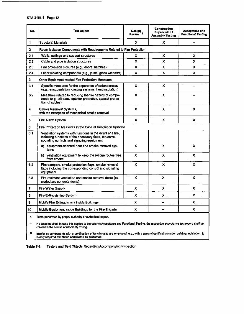
(2) The required tests and inspections are specified in Ta-ble 7-1. Type and extent of the tests depend on the specificcondition of the plant and shall be specified In each individualcase. The test instructions shall be presented in good timebefore acceptance and functional testing.
Note:See also 'Compilation of the Documents Required for the Testingof Nuclear Facilities by Construction Supervision Authorities' ofNovember 6, 1981 (GMBI 1981, page 518).
7.2.1 Design Review
Design review tests shall be performed as specified in Ta-ble 7-1.
7.2.2 Construction Supervision and Assembly Testing
(1) The construction materials and structural elements shallbe checked in the course of construction and assembly. Itshall also be checked that the plant components and equip-ment are manufactured and erected in accordance with thereviewed documents.
(2) Insofar as the manufacture of the construction materials,structural elements and equipment were already subject totests in the manufacturing plant, no further testing in this re-gard is necessary.
7.2.3 Acceptance and Functional Testing
(1) Acceptance and functional test shall be performed asspecified in Table 7-1.
(2) During acceptance testing, the completeness of the fireprotection measures shall be checked.
(3) After repairs and modifications, acceptance and func-tional testing of the respective structural elements, plants andequipment shall be repeated to the extent necessary.
c) technical drawings of the areas monitored by automaticfire detection and alarm systems and the areas where fires
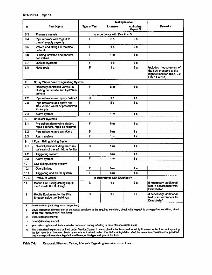
7.3 Inservice Inspections
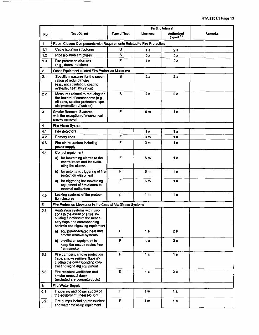
(1) The type of tests, the testing intervals and responsibili-ties regarding inservice inspections are specified in Table 7-2.The licensee shall ensure that the tests and inspections areperformed properly. Insofar as suitability certificates requireshorter testing intervals, these intervals shall be specified ineach individual case.When specifying other testing intervals than the ones listed inTable 7-2 the experience from inservice inspections as wellas the special design characteristics and quality assurancemeasures required in nuclear power plants shall, in closecoordination with the nuclear supervisory authority, be takeninto consideration.(2) A prolongation of the testing interval is permissible,provided, for reasons of, e.g., accessibility, certain tests arepossible only during refueling or reactor shutdown. However,the proper authority must consent to the prolongation of op-eration then required(3) In accordance with safety standard KTA 1202 testinginstructions are required for individual test objects listed inTable 7-2. These shall, in particular, specify the pant-relatedand equipment-related individual testing steps.
Note:Test requirements ar contained in the approvals and test certfi-cates under construction supervision legislation and in the rele-vant standards and guidelines
KTA2101.1 Pagell
(4) The existing combustible materials shall be checked atleast every three years regarding their correspondence withthe licensed fire protection concept as specified under Sec-tion 3.1.2.2. Within the framework of the fire protection roundafter every major revision, it shall be checked that the addi-tionally introduced fire loads have been properly removed.
7.4 Removal of Defects
The licensee shall ensure that any defects determined duringtesting are removed.
7.5 Documentation(1) Test records shall be prepared as proof of the perform-ance of the tests in accordance with Section 7.3 para.3.These test records shall, in particular, contain an evaluation ofthe test results, the detected defects, any necessary timelimits for the removal of defects and the signature of the testerand the date of the test.
Note:Details are specified in safety standards KTA 1202 andKTA 1404.
(2) The test records of inservice inspections shall be storedby licensee.
KTA2101.1 Page 12
No. Test Object Design suctionI Acceptance andReview ) Assembly Testing Functional Testing
1 Structural Materials X _ X
2 Room Isolation Components with Requirements Related to Fire Protection
2.1 Walls, ceilings and support structures X X X
2.2 Cable and pipe isolation structures X X X
2.3 Fire protection ciosures (e.g., doors, hatches) X j X
2.4 Other isolating components (e.g., joints, glass windows) X X X
3 Other Equipment-related Fire Protection Measures
3.1 Specific measures for the separation of redundancies X X(e.g., encapsulation, coating systems, heat insulation)
3.2 Measures related to reducing the fire hazard of compo- X Xnents (e.g., oil pans, splatter protection, special protec-tion of cables)
4 Smoke Removal Systems, X X Xwith the exception of mechanical smoke removal
5 Fire Alarm System X X X
6 Fire Protection Measures in the Case of Ventilation Systems
6.1 Ventilation systems with functions in the event of a fire,including functions of the necessary flaps, the corre-sponding controls and signaling equipment
a) equipment-oriented heat and smoke removal sys- X X Xtems
b) ventilation equipment to keep the rescue routes free X X Xfrom smoke
6.2 Fire dampers, smoke protection flaps, smoke removal X X Xflaps including the corresponding control and signalingequipment
6.3 Fire resistant ventilation and smoke removal ducts (ex- X X Xcluded are concrete ducts)
7 Fire Water Supply X X X
8 Fire Extinguishing System X X X
9 Mobile Fire Extinguishers inside Buildings X X
10 Mobile Equipment inside Buildings for the Fire Brigade X _ X
X Tests performed by proper authority or authorized expert.
- No tests required. In case this applies to the column Acceptance and Functional Testing, the respective acceptance test record shall becreated In the course of assembly testing.
1) Insofar as components with a certification of functionality are employed, e.g., with a general certification under building legislation, Itis only required that these certificates be presented.
Table 7-1: Testers and Test Objects Regarding Accompanying Inspection
KTA 2101.1 Page 13
l Testing Interval
No. Test Object | Type of Test Licensee AuthorizedRemarks
1 Room Closure Components with Requirements Related to Fire Protection
1.1 Cable isolation structures S 1 a 2 a
1.2 Pipe isolation structures S 2 a 2 a
1.3 Fire protection closures 1F a 2 a(e.g., doors, hatches)
2 Other Equipment-related Fire Protection Measures
2.1 Specific measures for the sepa- S 2a 2 aration of redundancies(e.g., encapsulation, coatingsystems, heat insulation)
2.2 Measures related to reducing the S 2 a 2 afire hazard of components (e.g.,oil pans, splatter protectors, spe-cial protection of cables)
3 Smoke Removal Systems, F 6 m 1 awith the exception of mechanicalsmoke removal
4 Fire Alarm System
4.1 Fire detectors F 1 a 1 a
4.2 Primary lines F 3 m I a X
4.3 Fire alarm centers including F 3 m I apower supply
4.4 Control equipment
a) for forwarding alarms to the F 6 m I acontrol room and for evalu-ating the alarms
b) for automatic triggering of fire F 6 m I aprotection equipment
c) for triggering the forwarding F 6 m I aequipment of fire alarms toexternal authorities
4.5 Locking systems of fire protec- F I m 1 ation closures
5 Fire Protection Measures in the Case of Ventilation Systems
5.1 Ventilation systems with func-tions in the event of a fire, in-cluding functions of the neces-sary flaps, the correspondingcontrols and signaling equipment
a) equipment-related heat and F 1 a 2 asmoke removal systems
b) ventilation equipment to F 1 a 2 akeep the rescue routes freefrom smoke
5.2 Fire dampers, smoke protection F I a 1 aflaps, smoke removal flaps in-cluding the corresponding con-trol and signaling equipment
5.3 Fire resistant ventilation and S 1 a 2 asmoke removal ducts(excluded are concrete ducts)
6 Fire Water Supply
6.1 Triggering and power supply ofthe equipment under No. 6.2
6.2 Fire pumps including pressurizeand water make-up equipment
KTA 2101.1 Page 14
Testing Interval
No. Test Object Type of Test Licensee Authorized RemarksI Expert 1)6.3 Pressure vessels In accordance with DruckbehV
6.4 Pipe network with regard to F 2 a 2 aoverall supply capacity
6.5 Valves and fittings in the pipe F I a 2 anetwork
6.6 Building isolation and penetra- F 1 m I ation valves
6.7 Outside hydrants F 1 a 2 a
6.8 Hose reels F I a 2 a Includes measurement ofthe flow pressure at thehighest location (Sec. 9.2DIN 14 461-1)
7 Spray Water Fire Extinguishing System
7.1 Remotely controlled valves (in- F 6 m I acluding pneumatic and hydraulicvalves)
7.2 Pipe networks and spray nozzles S I a I a
7.3 Pipe networks and spray noz- F 5a 5 azles, either, water or pressurizedair supply
7.4 Alarm system F 1 w I a
8 Sprinkler Systems
8.1 Pre-action alarm valve station, F 6 m 1 arapid openers, rapid air removal
8.2 Pipe networks and sprinklers S 6 m I a8.3 Alarm system [ F Iw I a
9 Foam Extinguishing System
9.1 Overall plant including mechani- 1 1Im 1nI acal seals of the admixture facility
9.2 Triggering system F 6 m I a9.3 Alarm system F 1 w 1 a
10 Gas Extinguishing System
10.1 Overall plant F 6 m 1 a
10.2 Triggering and alarm system F 6 m I I a
10.3 Pressure vessel in accordance with DruckbehV
11 Mobile Fire Extinguishing Equip- S 1 a 2 a if necessary, additionalment inside the Buildings test in accordance with
DruckbehV
12 Mobile Equipment for the Fire S 1 a 2 a if necessary, additionalBrigade inside the Buildings test in accordance with
DruckbehV
fluncuonal Wst tinauding visual inspecuore)S visual Inspection (comparison of the actual condition to the required condition, check with respect to damage-free condition, check
of the local measurement locations)w week(s) testing Intervalm month(s) testing intervala year(s) testing interval; tests are to be performed during refueling in case of Inaccessible areas1) The authorized expert (as defined under Section 2 para. 11) also checks the tests performed by licensee In the form of Inspecting
the test records of licensee. Tests by experts authorized under other fields of legislation shall be taken Into consideration, provided,they correspond to nuclear legislation with respect to type and goal of the tests.
Table 7-2: Responsibilities and Testing Intervals Regarding Inservice Inspections
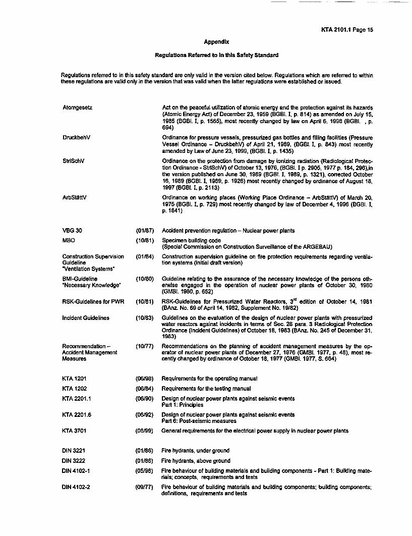
KTA 2101.1 Page 15
Appendix
Regulations Referred to In this Safety Standard
Regulations referred to in this safety standard are only valid in the version cited below. Regulations which are referred to withinthese regulations are valid only in the version that was valid when the latter regulations were established or issued.
Atomgesetz
DruckbehV
StrISchV
ArbSthttV
VBG 30
MBO
Construction SupervisionGuideline'Ventilation Systems'
BMI-Guideline'Necessary Knowledge'
RSK-Guidelines for PWR
Incident Guidelines
Recommendation -Accident ManagementMeasures
KTA 1201
KTA 1202
KTA 2201.1
KTA 2201.6
KTA 3701
DIN 3221
DIN 3222
DIN 4102-1
Act on the peaceful utilization of atomic energy and the protection against its hazards(Atomic Energy Act) of December 23, 1959 (BGBI. I, p. 814) as amended on July 15,1985 (BGBI. I, p. 1565), most recently changed by law on April 6, 1998 (BGBI. , p.694)
Ordinance for pressure vessels, pressurized gas bottles and filling facilities (PressureVessel Ordinance - DruckbehV) of April 21, 1989, (BGBI. I, p. 843) most recentlyamended by Law of June 23, 1999, (BGBI. I, p. 1435)
Ordinance on the protection from damage by ionizing radiation (Radiological Protec-ton Ordinance - StrISchV) of October 13, 1976, (BGBI. I p. 2905, 1977 p. 184, 296),inthe version published on June 30, 1989 (BGBI. 1, 1989, p. 1321), corrected October16, 1989 (BGBI. 1, 1989, p. 1926) most recently changed by ordinance of August 18,1997 (BGBI. I, p. 2113)
Ordinance on working places (Working Place Ordinance - ArbStattV) of March 20,1975 (BGBI. I, p. 729) most recently changed by law of December 4, 1996 (BGBI. I,p. 1841)
(01/87) Accident prevention regulation - Nuclear power plants
(10/81) Specimen building code(Special Commission on Construction Surveillance of the ARGEBAU)
(01/84) Construction supervision guideline on fire protection requirements regarding ventila-tion systems (initial draft version)
(10/80) Guideline relating to the assurance of the necessary knowledge of the persons oth-erwise engaged in the operation of nuclear power plants of October 30, 1980(GMBI. 1980, p. 652)
(10181) RSK-Guidelines for Pressurized Water Reactors, 3T edition of October 14, 1981(BAnz. No. 69 of April 14,1982, Supplement No. 19/82)
(10/83) Guidelines on the evaluation of the design of nuclear power plants with pressurizedwater reactors against Incidents in terms of Sec. 28 para. 3 Radiological ProtectionOrdinance (Incident Guidelines) of October 18, 1983 (BAnz. No. 245 of December 31,1983)
(10/77) Recommendations on the planning of accident management measures by the op-erator of nuclear power plants of December 27, 1976 (GMBI. 1977, p. 48), most re-cently changed by ordinance of October 18, 1977 (GMBI. 1977, S. 664)
(06/98) Requirements for the operating manual
(06/84) Requirements for the testing manual
(06/90) Design of nuclear power plants against seismic eventsPart 1: Principles
(06/92) Design of nuclear power plants against seismic eventsPart 6: Post-seismic measures
(06/99) General requirements for the electrical power supply in nuclear power plants
(01/86) Fire hydrants, under ground
(01/86)
(05/98)
Fire hydrants, above ground
Fire behaviour of building materials and building components - Part 1: Building mate-rials; concepts, requirements and tests
DIN 4102-2 (09177) Fire behaviour of building materials and building components; building components;definitions, requirements and tests
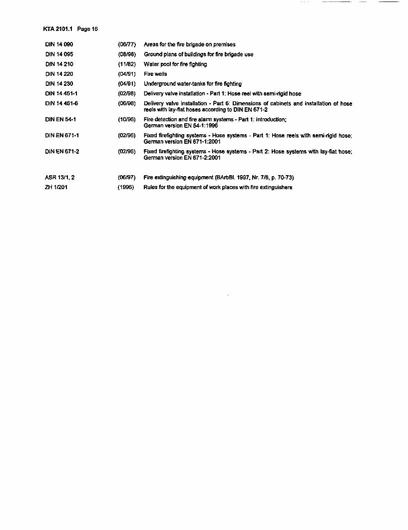
KTA 2101.1 Page 16
DIN 14 090
DIN 14 095
DIN 14 210
DIN 14 220
DIN 14 230
DIN 14 461-1
DIN 14 461-6
DIN EN 54-1
DIN EN 671-1
DIN EN 671-2
ASR 13/1, 2
ZH 1/201
(06/77)
(08/98)
(11/82)
(04/91)
Areas for the fire brigade on premises
Ground plans of buildings for fire brigade use
Water pool for fire fighting
Fire wells
(04/91) Underground water-tanks for fire fighting
(02/98) Delivery valve installation - Part 1: Hose reel with semi-rigid hose
(06/98) Delivery valve installation - Part 6: Dimensions of cabinets and installation of hosereels with lay-flat hoses according to DIN EN 671-2
(10/96) Fire detection and fire alarm systems - Part 1: Introduction;German version EN 54-1:1996
(02/96) Fixed firefighting systems - Hose systems - Part 1: Hose reels with semi-rigid hose;German version EN 671-1:2001
(02/96) Fixed firefighting systems - Hose systems - Part 2: Hose systems with lay-flat hose;German version EN 671-2:2001
(06/97)
(1996)
Fire extinguishing equipment (BArbBI. 1997, Nr. 718, p. 70-73)
Rules for the equipment of work places with fire extinguishers
Safety Standardsof theNuclear Safety Standards Commission (KTA)
KTA 2101.2 (12/2000)
Fire Protection in Nuclear Power PlantsPart 2: Fire Protection of Structural Plant Components
(Brandschutz in KernkraftwerkenTeil 2: Brandschutz an baulichen Anlagen)
If there is any doubt regarding the information contained in this translation, the German wording shall apply.
Editor:KTA-Geschaeftsstelle c/o Bundesamt fuer Strahlenschutz (BfS)Willy-Brandt-Str. 5 * 38226 Salzgitter * GermanyTelephone +49-(0)1888/333-(0)1621 * Telefax +49-(0)1888/333-1625
KTA SAFETY STANDARD
December Fire Protection in Nuclear Power Plants KTA 2101.22000 Part 2: Fire Protection of Structural Plant Components
CONTENTSFundamentals......................................................................................................................................................1
1 Scope.1
2 De ..nitions.1
3 Design of Structure-related Fire Protection Measures 1
4 Location and Accessibility of Buildings of Nuclear Power Plants .24.1 General Principles .24.2 Access Roads.24.3 Access Ways .24.4 Fire Brigade Engagement Areas .24.5 Free Movement Areas .2
5 Fire Compartments and Fire Sub-compartments .35.1 Fire Compartments .35.2 Fire Sub-compartments .35.3 Measures Regarding Adjacent Buildings and Building Comers .3
6 Structural Elements Enclosing Fire Compartments and Fire Sub-compartmnts .46.1 Structural Elements Enclosing Fire Compartments .46.2 Structural Elements Enclosing Fire Sub-compartments .46.3 Closures for Openings and Joints in Structural Elements Enclosing Fire Compartments and Fire
Sub-compartments.46.4 Structure-related Measures in the Case of Transformers .66.5 Measures to Counter Fire Flashover Between Extemal Structural Elements .6
7 Structural Elements for Rescue Routes .77.1 Structural Requirements .77.2 Joints in Enclosing Structural Elements .77.3 Flooring, Lining, Damming and Coating .7
8 Ventilation Systems, Heat and Smoke Removal Systems .78.1 General Principles .78.2 Ventilation Conduits, Fire Dampers and Smoke Dampers .78.3 Smoke Removal Conduits and Smoke Exhaust Dampers .88.4 Heat and smoke Removal .8
9 Cable Ducts, Cable Support Structures including Mounting Elements in the Vicinity of Cable FireShields .8
10 Tests and Inspections .8
Appendix A: Simplified Validation Procedure for Determining the Required Fire Resistance Rating ofStructure-related Fire Protection Measures .9
Appendix B: Regulations Referred to in this Safety Standard ........................................... 15
PLEASE NOTE: Only the original German version of this safety standard represents the joint resolution of the 50-member Nuclear Safety Standards Commission (Kemtechnischer Ausschuss, KTA). The German version was madepublic in Bundesanzeiger BAnz No. 106a on June 9, 2001. Copies may be ordered through the Carl HeymannsVerlag KG, Luxemburger Str. 449, 50939 Koeln, Germany (Telefax +49-221-94373603).
All questions regarding this English translation should please be directed to:
KTA-Geschaeftsstelle c/o BfS, Willy-Brandt-Str. 5, 38226 Salzgifter, Germany
Comments by the editor
Taking into account the meaning and usage of auxiliary verbs in the German language, in this translation the following agree-ments are effective:
shall
shall basically
shall normally
should
may
indicates a mandatory requirement,
is used in the case of mandatory requirements to which specific exceptions (and only those!) arepermitted. It Is a requirement of the KTA that these exceptions - other than those in the case of shallnormally - are specified in the text of the safety standard,
indicates a requirement to which exceptions are allowed. However, the exceptions used shall besubstantiated during the licensing procedure,
indicates a recommendation or an example of good practice,
indicates an acceptable or permissible method within the scope of this safety standard.
KTA 2101.2 Page I
Fundamentals
(1) The safety standards of the Nuclear Safety StandardsCommission (KTA) have the task of specifying those safetyrelated requirements which shall be met with regard to pre-cautions to be taken in accordance with the state of scienceand technology against the damage arising from the con-struction and operation of the facility (Sec. 7 para. 2 sub-para. 3 Atomic Energy Act), in order to attain the protectiongoals specified in the Atomic Energy Act and RadiologicalProtection Ordinance (StrlSchV) and which are further de-tailed in 'Safety Criteria for Nuclear Power Plants' and in'Guidelines for the Assessment of the Design of PWR Nu-clear Power Plants against Incidents pursuant to Sec. 28para. 3 of the Radiological Protection Ordinance (StrlSchV) -Incident Guidelines".
(2) Criterion 2.7 'Fire and Explosion Protection' of theSafety Criteria for Nuclear Power Plants specifies that protec-tion measures shall be taken against fires in nuclear powerplants. In accordance with Table II of the Incident Guidelines,plant-intemal fires belong to those design basis accidents(incidents) for which precautionary plant engineering meas-ures must be taken and which on account of these measuresdo not have any relevance with respect to radiological effectson the environment.
The details of these precautionary measures with respect tostructure-related fire protection measures are specified in thissafety standard.
(3) In setting up this safety standard it is assumed that thebuilding codes, fire protection laws and fire protection regula-tions of the individual German states (LAnder), the WorkplaceOrdinance, the German Accident Prevention Regulations ofthe trade unions and other regulations under public law aremet. If the specifics of the nuclear power plant require devia-tions from laws, ordinances or other regulations under publiclaw or from the German Accident Prevention Regulations(UVV), then the particular deviations and exemptions shall behandled on a case-by-case basis in accordance with the pro-cedures specified in these individual regulations.
(4) This safety standard KTA 2101.2 supplements the safetystandards:KTA 2101.1 Fire protection in nuclear power plants;
Part 1: Basic requirements
KTA 2101.3 Fire protection in nuclear power plants;Part 3: Fire protection of mechanical and electri-cal plant components
Note:Additional relevant KTA safety standards are listed inKTA 2101.1.
1 Scope
This safety standard applies to nuclear power plants with lightwater reactors.
It applies to the protection from building-intemal and building-extemal fires, in particular, with respect toa) plant components, the safety function of which are neces-
sary to meet the protection goals on which the Safety Cri-teria are based, i.e.,aa) control of reactivity,ab) cooling of fuel assemblies,ac) confinement of radioactive substances andad) limitation of radiation exposure,
b) the structural plant components surrounding these plantcomponents and
c) the plant personnel.
Note:These structural plant components include, e.g., the reactorbuilding, the reactor auxiliary building, the nuclear servicesbuilding as well as the structural plant components of the serv-ice cooling water circuits, the emergency standby building, theemergency feed water building, the switch gear building, theturbine building of boiling water reactors, the emergency powergenerator building, the pipe and cable ducts or channels be-tween the aforementioned buildings.
2 DefinitionsNote:Additional definitions are given in safety standards KTA 2101.1and KTA 2101.3.
(1) Acceptance and Functional TestingAcceptance and functional testing comprises testing andevaluation of the constructed and assembled componentsand systems as well as their functional behavior.
(2) Assembly TestingAssembly testing is the performance of tests by the manu-facturer or at the construction site of the finished componentsand systems or those still under construction to show thatthey are in conformance with the design-reviewed documents.
(3) Smoke Exhaust DampersSmoke exhaust dampers are devices that are opened in theevent of fire and are intended for heat and smoke removal.
(4) Smoke Removal ConduitsSmoke removal conduits are conduits, e.g. ducts and chan-nels, for the removal of smoke or heat in the event of fire.
(5) Protected CorridorA protected corridor is a corridor that is meant to be used asescape route. It leads to the necessary stairways or from thenecessary stairways to the outside.
(6) Ventilation ConduitsVentilation conduits are conduits, e.g. ducts and channels,meant for the transport of air.
(7) Smoke DampersSmoke dampers are active isolating devices against smokethat are triggered by the fire variable 'smoke".
(8) Airlock AnnexesAirlock annexes are rooms arranged in advance of the per-sonnel locks (in accordance with safety standard KTA 3402)inside the reactor containment vessel of a pressurized light-water reactor. They are intended to be used as rescue route.
(9) Necessary StairwayA necessary stairway Is a stairway that contains the staircaseneeded to get to a higher-than-ground-level building floor andthat is intended to be used as rescue route.
(10) Design ReviewDesign review is the evaluation of the documents that areprepared for manufacturing, e.g., schedules and plans, writteninstructions, technical drawings and calculations, with respectto whether or not they meet the provisions of the license.
3 Design of Structure-related Fire ProtectionMeasures
(1) Insofar as no prior experience is available, it shall beconfirmed experimentally or analytically, or by analogy orplausibility considerations that the structure-related fire pro-tection measures will withstand the fire effects determined inaccordance with Sec. 3.1.2.3 KTA 2101.1 without losing their
KTA 2101.2 Page 2
function regarding fire protection (e.g., stability, room isola-tion).
(2) In the case of an analytical validation it is permissible touse simplified procedures, provided, the calculations lead toconservative results.
Note:One such conservative procedure is presented in Appendix A.
(3) In the case of analogy considerations, they shall be basedon referential results of experimental or analytical confirmationsthat were performed for comparable structure-related fire pro-tection measures (comparable to, e.g., type of construction,building materials, dimensions) und for comparable loadings(e.g., temperature effects, operational loading, if necessaryadditional loading due to design basis accidents (incidents)).
(4) Plausibility consideration may be performed on the basisof the design of structure-related fire protection measures forother load cases with the objective of proving that the actualdesign can be considered as ensured to be sufficiently safe.
(5) It is not required to prove the fire resistance rating ofstructure-related fire protection measures during earthquakes,provided, they are designed in accordance with KTA 2201.1for the design-basis earthquake.
(6) If additional requirements in accordance with Sec. 3.1.1para. 6 KTA 2101.1 must be considered in the design (e.g.,gas leak tightness, lower component temperature on the farside of the fire) then the determination of the fire resistancerating of the components shall be based also on these re-quirements.
The testing guidelines and criteria in accordance with techni-cal standards series DIN 4102 shall be applied, however, onlyafter adjustment to the above requirements.
(7) If additional events in accordance with Sec. 3.1.1 para. 7KTA 2101.1 must be considered in the design, then the de-termination of the fire resistance rating of the componentsshall be based also on these events.
(8) Those structure-related fire protection measures the fireprotection function of which must be ensured even afterearthquakes shall be designed in accordance with Sec. 3.2.3para. 2 KTA 2101.1.
4 Location and Accessibility of Buildings of NuclearPower Plants
4.1 General Principles
(1) The buildings of nuclear power plants shall be arrangedtaking operational and, additionally, the following require-ments into consideration:a) the fire protective separation by the distance between
buildings,b) the rapid and safe escape and rescue of persons in case
of an emergency andc) the access ways for danger aversion missions.
(2) The requirements in accordance with DIN 14 090 shallbasically be applied and those specified under Sections 4.2through 4.5 shall additionally be applied.
(3) Deviating specifications regarding the location and ac-cessibility of the buildings require the consent of the properauthorities in the course of the licensing procedure.
(4) In planning accident management measures, the locationof the personnel assembly points shall be specified such thatthey present no hindrance to the mission of the fire brigade.
4.2 Access Roads
(1) Basically all surface areas on the site of the power plantthat are used for vehicular traffic shall be designed at least asa fire brigade surface area in accordance with DIN 14 090.
Exceptions are permissible in the case of remote vehicularsurface areas, e.g., parking lots, provided, they have no sig-nificance with respect to the access to buildings or plant com-ponents. In case they have a reduced load-carrying capacityin accordance with DIN 14 090 they shall be marked accord-ingly.
(2) Buildings with safety-related system and plant compo-nents shall basically be accessible via two independent ac-cess routes that are at least 6 meters wide. Exceptions arepermissible in the case of access routes to remote buildingswith a low fire load density, e.g., the auxiliary service waterpump building.
(3) The width of the access route may be reduced to aminimum of 3.5 meters if plant engineering so requires. How-ever, the length of such bottlenecks shall be limited to amaximum of 40 meters.
4.3 Access Ways
(1) In view of rescue and danger aversion missions, it shallbe possible to open the access ways from the outside andsecure them in the open position during emergencies. Thisalso applies to inside access ways to enclosed building re-gions.
(2) The doors of the access ways dedicated to rescue anddanger aversion missions shall open to their full width andbasically in the direction of escape. Exceptions are permissi-ble for reasons of plant engineering, e.g., in the case of roomswhere the ventilation system keeps a below-atmosphericpressure or if only a small number of persons have to dependon these doors.
4.4 Fire Brigade Engagement Areas
(1) Insofar as the necessary rescue routes in buildings leadto windows and roof surfaces that can be used for rescueoperations, individual fire brigade engagement areas in ac-cordance with DIN 14 090 shall be assigned to these windowsand roof surfaces for the positioning of rescue hoist vehicles.
(2) Fire brigade engagement areas may be integrated intodriveways such that, in accordance with DIN 14 090, a pas-sage of at least 5 meters remains next to the fire brigadeengagement area.
4.5 Free Movement Areas
(1) A free movement area with an area of at least 7 metersby 40 meters shall be assigned to each of the necessaryaccess point of the buildings with regard to rescue and dangeraversion missions. The distance between the free movementarea and the assigned access points shall normally not ex-ceed 25 meters.
(2) The free movement areas may be integrated into drive-ways such that, in accordance with DIN 14 090, a driveway ofat least 3 meters remains free next to the free movementarea.
(3) Walk ways or other similarly paved ways that are bor-dered off by curb stones may be integrated up to a width of2 meters into the free movement areas.
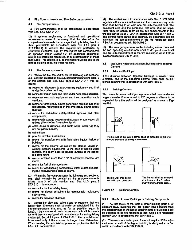
KTA 2101.2 Page 3
5 Fire Compartments and Fire Sub-compartments
5.1 Fire Compartments
(1) Fire compartments shall be established in accordancewith Sec. 4.1.3 KTA 2101.1.
(2) If systems engineering or functional and operationalrequirements make it necessary that the size of a firecompartments exceeds the size specified by building law it is,then, permissible (in accordance with Sec. 4.1.3 para. 2KTA 2101.1) to achieve the required fire protection byequivalent measures, e.g., by creating fire sub-compartmentsas specified under Section 5.2, by additional equipment-related fire protection measures, or by a combination of thesemeasures. This applies, e.g., to the reactor building and to theturbine building of boiling water reactors.
5.2 Fire Sub-compartments
(1) Within the fire compartments the following sub-sections,e.g., shall be created as fire sub-compartments taking para. 3of this section and Sec. 4.1.3 para. 3 KTA 2101.1 into ac-count,:a) rooms for electronic data processing equipment and their
under-floor cable sections,b) rooms for switch gear and their under-floor cable sections,c) rooms for electronic equipment and their under-floor cable
sections,d) rooms for emergency power generation facilities and their
fuel depots, redundancies of the emergency power supplyfacilities,
e) rooms for redundant safety-related systems and plantcomponents,
f) rooms with storage vessels and facilities for lubrication oil,turbine oil and other flammable liquids,
g) cable ducts or channels and cable wells, insofar as theyare not part of a room,
h) cable floors,i) pool for new fuel assemblies,j) rooms for transformers with flammable liquids inside of
buildings,k) rooms for the external oil supply (oil storage vessel in-
cluding auxiliary equipment). In the case of boiling waterreactors, this room shall be located outside of the controlrod drive room.
I) rooms in which more that 3 m3 of activated charcoal arestored,
m) rooms for fuel oil storage tanks,n) rooms for conditioning combustible waste material includ-
ing the corresponding storage rooms.
(2) Within the fire compartments the following sub-sections,e.g., shall normally be created as fire sub-compartmentstaking para. 3 of this section and Sec. 4.1.3 para. 3KTA 2101.1 into account,:a) rooms for the fuel oil day tanks,b) rooms for closed containers for combustible radioactive
substances.c) rooms for activated charcoal.
(3) Accessible pipe and cable ducts or channels that arelonger than 50 meters shall basically be subdivided into firesub-compartments that are, as far as possible, equal inlength. If the channels do not contain any combustible materi-als or if they are equipped with a stationary fire extinguishingsystem (cf. Sec. 4.2.4 para. I KTA 2101.1) then a subdivisionis required only if the channel is longer than 100 meters.When creating the subdivision, personnel protection shall betaken into consideration.
(4) The control room in accordance with Sec. 3 KTA 3904together with its functional areas and the corresponding cablefloor shall belong to at least one fire sub-compartment. Thedocument area and the personnel rest area shall be sepa-rated from the control room as fire sub-compartments in thefire resistance class F 90-A in accordance with DIN 4102-2.The control room annex shall normally be separated into anindividual fire sub-compartment in the fire resistance classF 30-A in accordance with DIN 4102-2.
(5) The emergency control center including annex room andthe corresponding conduit room shall be designed as at leastone fire sub-compartment in the fire resistance class F 90-Ain accordance with DIN 4102-2.
5.3 Measures Regarding Adjacent Buildings and BuildingComers
5.3.1 Adjacent Buildings
If the distance between adjacent buildings is smaller than5 meters, one of the opposing external walls shall be de-signed as a fire wall in accordance with DIN 4102-3.
5.3.2 Building Comers
The comer between building components that meet under anangle a smaller than or equal to 120 degrees and have to beseparated by a fire wall shall be designed as shown in Fig-ure S-1.
ALl
The fire wall at the Inside corner shall be extended in either ofthe two directions to a length 2 5 meters.
The fire wall shall be ex-tended in both directions.
Figure 5-1: Building Comers
The fire wall shall be arrangedat a distance of 2 5 metersaway from the inside corner.
5.3.3 Roofs of Lower Buildings or Building Components
(1) The roof levels or the roofs of lower building parts or ofadjacent lower buildings that are closer than 5 meters fromthe external walls of the larger building parts or buildings shallbe designed to be fire resistant at least with a fire resistancerating F 90-A in accordance with DIN 4102-2.
(2) The measures under para. 1 are not required if the adja-cent external wall of the higher building Is designed as a firewall in accordance with DIN 4102-3.
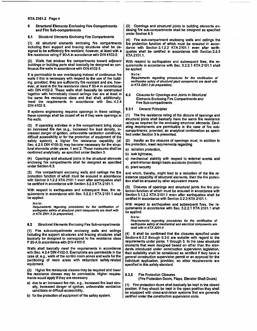
KTA 2101.2 Page 4
6 Structural Elements Enclosing Fire Compartmentsand Fire Sub-compartments
6.1 Structural Elements Enclosing Fire Compartments
(1) All structural elements enclosing fire compartmentsincluding their support and bracing structures shall be de-signed to be sufficiently fire resistant, however, at least with afire resistance rating F 90-A in accordance with DIN 4102-2.
(2) Walls that enclose fire compartments toward adjacentbuildings or building parts shall basically be designed as con-tinuous fire walls in accordance with DIN 4102-3.
It is permissible to use overlapping instead of continuous firewalls if this is necessary with respect to the use of the build-ing, provided, they are sufficiently fire resistant and are, how-ever, at least In the fire resistance class F 90-A in accordancewith DIN 4102-2. These walls shall basically be constructedtogether with hermetically closed ceilings that are at least inthe same fire resistance class and that shall, additionally,meet the requirements in accordance with Sec. 4.2.4DIN 4102-3.
If systems engineering requires openings in these ceilings,these openings shall be closed off as if they were openings infire walls.
(3) If operating activities in a fire compartment bring aboutan increased fire risk (e.g., increased fire load density, in-creased danger of ignition, unfavorable ventilation conditions,difficult accessibility or for the protection of equipment of thesafety system), a higher fire resistance capability (cf.Sec. 4.2.5 DIN 4102-3) may become necessary for the struc-tural elements under pares. I and 2. These measures shall beconfirmed analytically as specified under Section 3.
(4) Openings and structural joints in the structural elementsenclosing fire compartments shall be designed as specifiedunder Section 6.3.
(5) Fire compartment enclosing walls and ceilings the fireprotection function of which must be ensured in accordancewith Section 3.1.2.2 KTA 2101.1 even after earthquakes shallbe certified in accordance with Section 3.2.3 KTA 2101.1.
With respect to earthquakes and subsequent fires, the re-quirements in accordance with Sec. 3.2.2.1 KTA 2101.1 shallbe applied.
Note:Requirements regarding procedures for the certification ofearthquake safety of structural plant components are dealt within KTA 2201.3 (in preparation).
6.2 Structural Elements Enclosing Fire Sub-compartments
(1) Fire sub-compartments enclosing walls and ceilingsincluding the support structures and bracing structures shallbasically be designed to correspond to fire resistance classF 90-A in accordance with DIN 4102-2.
Walls shall basically meet the requirements in accordancewith Sec. 4.2.4 DIN 4102-3. Exemptions are permissible in thecase of, e.g., walls of the control room annex and walls for thepartitioning of room areas with redundant safety-relatedequipment.
(2) Higher fire resistance classes may be required and lowerfire resistance classes may be permissible. Higher require-ments would apply if they are necessarya) due to an increased fire risk, e.g., increased fire load den-
sity, increased danger of ignition, unfavorable ventilationconditions or difficult accessibility,
(3) Openings and structural joints in building elements en-closing fire sub-compartments shall be designed as specifiedunder Section 6.3.
(4) Fire sub-compartment enclosing walls and ceilings thefire protection function of which must be ensured in accor-dance with Section 3.1.2.2 KTA 2101.1 even after earth-quakes shall be certified in accordance with Section 3.2.3KTA 2101.1.
With respect to earthquakes and subsequent fires, the re-quirements in accordance with Sec. 3.2.2.1 KTA 2101.1 shallbe applied.
Note:Requirements regarding procedures for the certification ofearthquake safety of structural plant components are dealt within KTA 2201.3 (in preparation).
6.3 Closures for Openings and Joints in StructuralElements Enclosing Fire Compartments andFire Sub-compartments
6.3.1 General Principles
(1) The fire resistance rating of the closure of openings andstructural joints shall basically have the same fire resistancerating as required for the enclosing structural elements. Devi-ating requirements are permissible in the case of fire sub-compartments, provided, an analytical confirmation as speci-fied under Section 3 is presented.
(2) Insofar as the closures of openings must, in addition tofire protection, meet requirements regardinga) radiation protection,b) leak tightness,c) mechanical stability with respect to external events and
plant-intemal design basis accidents (incident)d) plant security
and which, thereby, might lead to a reduction of the fire re-sistance capability of structural elements, then the fire protec-tion shall be ensured by other equivalent means.
(3) Closures of openings and structural joints the fire pro-tection function of which must be ensured In accordance withSection 3.1.2.2 KTA 2101.1 even after earthquakes shall becertified in accordance with Section 3.2.3 KTA 2101.1.
With respect to earthquakes and subsequent fires, the re-quirements in accordance with Sec. 3.2.2.1 KTA 2101.1 shallbe applied.
Note:Requirements regarding procedures for the certification ofearthquake safety of mechanical and electrical components aredealt with In KTA 2201.4
(4) It shall be confirmed that the closures specified underSections 6.3.2 through 6.3.6 are suitable with regard to therequirements under paras. 1 through 3. In the case structuralelements that were designed based on other than the stan-dards Introduced under construction supervision legislation,their suitability shall be considered as certified if they have ageneral construction supervision permit or an approval for theindividual application, provided, no other requirements arespecified in this safety standard.
6.3.2 Fire Protection Closures(Fire Protection Doors, Flaps, Elevator Shaft Doors)
(1) Fire protection doors shall basically be kept in the dosedposition. If they should be kept in the open position they shallbe equipped with close-and-retain systems that are generallycertified under the construction supervision code.b) for the protection of equipment of the safety system.
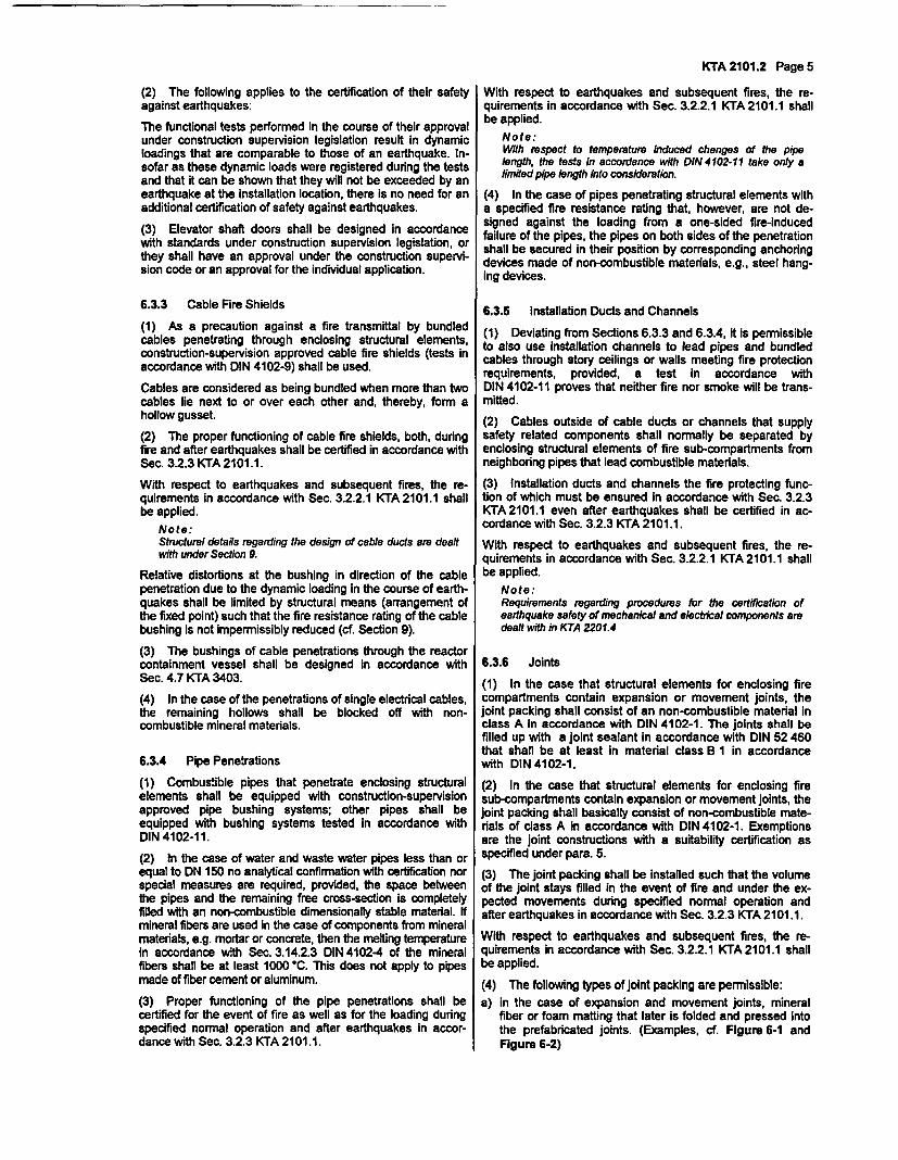
(2) The following applies to the certification of their safetyagainst earthquakes:
The functional tests performed in the course of their approvalunder construction supervision legislation result in dynamicloadings that are comparable to those of an earthquake. In-sofar as these dynamic loads were registered during the testsand that it can be shown that they will not be exceeded by anearthquake at the installation location, there is no need for anadditional certification of safety against earthquakes.
(3) Elevator shaft doors shall be designed in accordancewith standards under construction supervision legislation, orthey shall have an approval under the construction supervi-sion code or an approval for the individual application.
6.3.3 Cable Fire Shields
(1) As a precaution against a fire transmittal by bundledcables penetrating through enclosing structural elements,construction-supervision approved cable fire shields (tests inaccordance with DIN 4102-9) shall be used.
Cables are considered as being bundled when more than twocables lie next to or over each other and, thereby, form ahollow gusset.
(2) The proper functioning of cable fire shields, both, duringfire and after earthquakes shall be certified in accordance withSec. 3.2.3 KTA 2101.1.
With respect to earthquakes and subsequent fires, the re-quirements in accordance with Sec. 3.2.2.1 KTA 2101.1 shallbe applied.
Note:Structural details regarding the design of cable ducts are dealtwith under Section 9.
Relative distortions at the bushing in direction of the cablepenetration due to the dynamic loading in the course of earth-quakes shall be limited by structural means (arrangement ofthe fixed point) such that the fire resistance rating of the cablebushing is not Impermissibly reduced (cf. Section 9).
(3) The bushings of cable penetrations through the reactorcontainment vessel shall be designed in accordance withSec. 4.7 KTA 3403.
(4) In the case of the penetrations of single electrical cables,the remaining hollows shall be blocked off with non-combustible mineral materials.
6.3.4 Pipe Penetrations
(1) Combustible pipes that penetrate enclosing structuralelements shall be equipped with construction-superisionapproved pipe bushing systems; other pipes shall beequipped with bushing systems tested in accordance withDIN 41 02-11.
(2) In the case of water and waste water pipes less than orequal to DN 150 no analytical confirmation with certification norspecial measures are required, provided, the space betweenthe pipes and the remaining free cross-section is completelyfilled with an non-combustible dimensionally stable material. Ifmineral fibers are used in the case of components from mineralmaterials, e.g. mortar or concrete, then the melting temperaturein accordance with Sec. 3.14.2.3 DIN 4102-4 of the mineralfibers shall be at least 1000 'C. This does not apply to pipesmade of fiber cement or aluminum.
(3) Proper functioning of the pipe penetrations shall becertified for the event of fire as well as for the loading duringspecified normal operation and after earthquakes in accor-dance with Sec. 3.2.3 KTA 2101.1.
KTA 2101.2 Page 5
With respect to earthquakes and subsequent fires, the re-quirements in accordance with Sec. 3.2.2.1 KTA 2101.1 shallbe applied.
Note:With respect to temperature induced changes of the pipelength, the tests in accordance with DIN 4102-11 take only alimited pipe length into consideration.
(4) In the case of pipes penetrating structural elements witha specified fire resistance rating that, however, are not de-signed against the loading from a one-sided fire-inducedfailure of the pipes, the pipes on both sides of the penetrationshall be secured in their position by corresponding anchoringdevices made of non-combustible materials, e.g., steel hang-ing devices.
6.3.5 Installation Ducts and Channels
(1) Deviating from Sections 6.3.3 and 6.3.4, it is permissibleto also use installation channels to lead pipes and bundledcables through story ceilings or walls meeting fire protectionrequirements, provided, a test in accordance withDIN 4102-11 proves that neither fire nor smoke will be trans-mitted.
(2) Cables outside of cable ducts or channels that supplysafety related components shall normally be separated byenclosing structural elements of fire sub-compartments fromneighboring pipes that lead combustible materials,
(3) Installation ducts and channels the fire protecting func-tion of which must be ensured in accordance with Sec. 3.2.3KTA 2101.1 even after earthquakes shall be certified in ac-cordance with Sec. 3.2.3 KTA 2101.1.
With respect to earthquakes and subsequent fires, the re-quirements in accordance with Sec. 3.2.2.1 KTA 2101.1 shallbe applied.
Note:Requirements regarding procedures for the certification ofearthquake safety of mechanical and electrical components aredealt with in KTA 2201.4
6.3.6 Joints
(1) In the case that structural elements for enclosing firecompartments contain expansion or movement joints, thejoint packing shall consist of an non-combustible material Inclass A in accordance with DIN 4102-1. The joints shall befilled up with a joint sealant in accordance with DIN 52 460that shall be at least In material class B 1 in accordancewith DIN 4102-1.
(2) In the case that structural elements for enclosing firesub-compartments contain expansion or movement joints, thejoint packing shall basically consist of non-combustible mate-rials of class A in accordance with DIN 4102-1. Exemptionsare the joint constructions with a suitability certification asspecified under para. 5.
(3) The joint packing shall be installed such that the volumeof the joint stays filled in the event of fire and under the ex-pected movements during specified normal operation andafter earthquakes In accordance with Sec. 3.2.3 KTA 2101.1.
With respect to earthquakes and subsequent fires, the re-quirements in accordance with Sec. 3.2.2.1 KTA 2101.1 shallbe applied.
(4) The following types of joint packing are permissible:
a) in the case of expansion and movement joints, mineralfiber or foam matting that later is folded and pressed intothe prefabricated joints. (Examples, cf. Figure 6-1 andFigure 6-2)
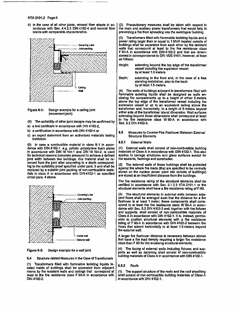
KTA 2101.2 Page 6
b) in the case of all other joints, mineral fiber sheets in ac-cordance with Sec. 4.4.2.3 DIN 4102-4 and mineral fiberbraids with comparable characteristics.
(2) Precautionary measures shall be taken with respect tothe main and auxiliary power transformers that would help inpreventing a fire from spreading into the switchgear building.
(3) Transformers filled with flammable isolating liquids and apower rating larger than or equal to I MVA located outside ofbuildings shall be separated from each other by fire resistantwalls that correspond at least to the fire resistance classF 90-A in accordance with DIN 4102-2 and that are dimen-sioned in correspondence to DIN VDE 0101, however, at leastas follows:
Height: extending beyond the top edge of the transformervessel including the expansion vessel:by at least 1.0 meters
Depth: extending to the front and, in the case of a freestanding installation, also to the back:by at least 1.5 meters.
(4) The walls of buildings adjacent to transformers filled withflammable isolating liquids shall be designed as walls en-closing fire compartments up to a height of either 5 metersabove the top edge of the transformer vessel including theexpansion vessel or up to an equivalent ceiling above thetransformer and, horizontally, to a length of 5 meters beyondeither side of the transformer lateral dimension. Wall surfacesextending beyond these dimensions shall correspond at leastto the fire resistance class W 90-A In accordance withSec. 5.2 DIN 4102-3.
Figure 6-1: Design example for a ceiling joint(movement joint)
(5) The suitability of other joint designs may be confirmed by
a) a test certificate in accordance with DIN 4102-2,
b) a certification in accordance with DIN 4102-4 or
c) an expert statement from an authorized materials testinginstitution.
(6) In case a combustible material in class B I in accor-dance with DIN 4102-1, e.g. cellular polystyrene foam platesin accordance with DIN 18 164-1 and DIN 18 164-2, is usedfor technical reasons (concrete pressure) to achieve a definedjoint width between two buildings, this material shall be re-moved from the joint after concreting to a depth correspond-ing to the suitability proof specified under para. 5 and shall bereplaced by a suitable joint packing of non-combustible mate-rials in class A in accordance with DIN 4102-1 as specifiedunder para. 4 above.
o/ffiXigX |Covering L-bar
/JWint p atici
Inside wdOutside wi
Figure 6-2: Design example for a wall joint
6A Structure-related Measures in the Case of Transformers
(1) Transformers filled with flammable isolating liquids lo-cated inside of buildings shall be separated from adjacentrooms by fire resistant walls and ceilings that correspond atleast to the fire resistance class F 90-A in accordance withDIN 4102-2.
6.5 Measures to Counter Fire Flashover Between ExternalStructural Elements
6.5.1 Extemal Walls
(1) External walls shall consist of non-combustible buildingmaterials of Class A in accordance with DIN 4102-1. This alsoapplies to barrage structures and glass surfaces except forthe sealants, flashings and sunshades.
(2) The external walls of those buildings shall be protectedagainst fire where fire loads (that are specified to be normallystored on the nuclear power plant site outside of buildings)are stored at an insufficient distance from the buildings.
The fire resistance rating of the structural elements shall becertified in accordance with Sec. 3.1.2.3 KTA 2101.1 or thestructural elements shall have a fire resistance rating of F-90.
(3) The structural elements in external walls between adja-cent floors shall be arranged such that the distance for a fireflashover Is at least 1 meter, these components shall corre-spond to at least the fire resistance class W 90-A in accor-dance with Sec. 5.2 DIN 4102-3 and, together with the fixturesand supports, shall consist of non-combustible materials ofClass A in accordance with DIN 4102-1. It is, instead, permis-sible to position structural elements with a fire resistancerating of F 90-A in accordance with DIN 4102-2 between thefloors that extend horizontally to at least 1.5 meters beyondthe external wall.
A larger fire flashover distance is necessary between storiesthat have a fire load density requiring a larger fire resistanceclass than F 90 for the enclosing structural elements.
(4) The facing of external walls including fixtures and sup-ports as well as damming shall consist of non-combustiblebuilding materials of Class A in accordance with DIN 4102-1.
6.5.2 Roofs
(1) The support structure of the roofs and the roof sheathingshall consist of non-combustible building materials of Class Ain accordance with DIN 4102-1.
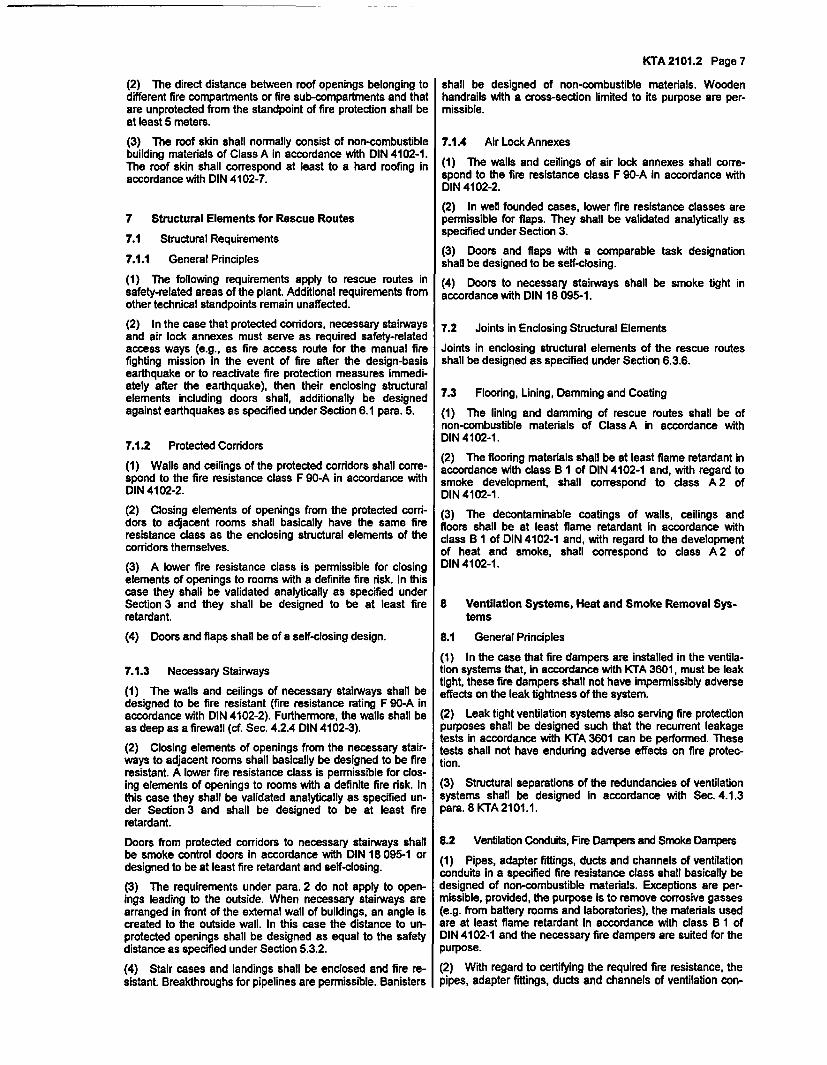
(2) The direct distance between roof openings belonging todifferent fire compartments or fire sub-compartments and thatare unprotected from the standpoint of fire protection shall beat least 5 meters.
(3) The roof skin shall normally consist of non-combustiblebuilding materials of Class A in accordance with DIN 4102-1.The roof skin shall correspond at least to a hard roofing inaccordance with DIN 4102-7.
7 Structural Elements for Rescue Routes
7.1 Structural Requirements
7.1.1 General Principles
(1) The following requirements apply to rescue routes insafety-related areas of the plant Additional requirements fromother technical standpoints remain unaffected.
(2) In the case that protected corridors, necessary stairwaysand air lock annexes must serve as required safety-relatedaccess ways (e.g., as fire access route for the manual firefighting mission in the event of fire after the design-basisearthquake or to reactivate fire protection measures immedi-ately after the earthquake), then their enclosing structuralelements including doors shall, additionally be designedagainst earthquakes as specified under Section 6.1 para. 5.
7.1.2 Protected Corridors
(1) Walls and ceilings of the protected corridors shall corre-spond to the fire resistance class F 90-A in accordance withDIN 4102-2.
(2) Closing elements of openings from the protected corri-dors to adjacent rooms shall basically have the same fireresistance class as the enclosing structural elements of thecorridors themselves.
(3) A lower fire resistance class is permissible for closingelements of openings to rooms with a definite fire risk. In thiscase they shall be validated analytically as specified underSection 3 and they shall be designed to be at least fireretardant.
(4) Doors and flaps shall be of a self-closing design.
7.1.3 Necessary Stairways
(1) The walls and ceilings of necessary stairways shall bedesigned to be fire resistant (fire resistance rating F 90-A inaccordance with DIN 4102-2). Furthermore, the walls shall beas deep as a firewall (cf. Sec. 4.2.4 DIN 4102-3).
(2) Closing elements of openings from the necessary stair-ways to adjacent rooms shall basically be designed to be fireresistant. A lower fire resistance class is permissible for clos-ing elements of openings to rooms with a definite fire risk. Inthis case they shall be validated analytically as specified un-der Section 3 and shall be designed to be at least fireretardant.
Doors from protected corridors to necessary stairways shallbe smoke control doors in accordance with DIN 18 095-1 ordesigned to be at least fire retardant and self-closing.
(3) The requirements under para. 2 do not apply to open-ings leading to the outside. When necessary stairways arearranged in front of the external wall of buildings, an angle iscreated to the outside wall. In this case the distance to un-protected openings shall be designed as equal to the safetydistance as specified under Section 5.3.2.
(4) Stair cases and landings shall be enclosed and fire re-sistant. Breakthroughs for pipelines are permissible. Banisters
KTA 2101.2 Page 7
shall be designed of non-combustible materials. Woodenhandrails with a cross-section limited to its purpose are per-missible.
7.1.4 Air Lock Annexes
(1) The walls and ceilings of air lock annexes shall corre-spond to the fire resistance class F 90-A in accordance withDIN 4102-2.
(2) In well founded cases, lower fire resistance classes arepermissible for flaps. They shall be validated analytically asspecified under Section 3.
(3) Doors and flaps with a comparable task designationshall be designed to be self-dosing.
(4) Doors to necessary stairways shall be smoke tight inaccordance with DIN 18 095-1.
7.2 Joints in Enclosing Structural Elements
Joints in enclosing structural elements of the rescue routesshall be designed as specified under Section 6.3.6.
7.3 Flooring, Lining, Damming and Coating
(1) The lining and damming of rescue routes shall be ofnon-combustible materials of Class A in accordance withDIN 4102-1.
(2) The flooring materials shall be at least flame retardant inaccordance with class B I of DIN 4102-1 and, with regard tosmoke development, shall correspond to class A 2 ofDIN 4102-1.
(3) The decontaminable coatings of walls, ceilings andfloors shall be at least flame retardant in accordance withclass B 1 of DIN 4102-1 and, with regard to the developmentof heat and smoke, shall correspond to class A 2 ofDIN 4102-1.
8 Ventilation Systems, Heat and Smoke Removal Sys-tems
8.1 General Principles
(1) In the case that fire dampers are installed in the ventila-tion systems that, in accordance with KTA 3601, must be leaktight, these fire dampers shall not have impermissibly adverseeffects on the leak tightness of the system.
(2) Leak tight ventilation systems also serving fire protectionpurposes shall be designed such that the recurrent leakagetests in accordance with KTA 3601 can be performed. Thesetests shall not have enduring adverse effects on fire protec-tion.
(3) Structural separations of the redundancies of ventilationsystems shall be designed in accordance with Sec. 4.1.3para. 8 KTA 2101.1.
8.2 Ventilation Conduits, Fire Dampers and Smoke Dampers
(1) Pipes, adapter fittings, ducts and channels of ventilationconduits in a specified fire resistance class shall basically bedesigned of non-combustible materials. Exceptions are per-missible, provided, the purpose is to remove corrosive gasses(e.g. from battery rooms and laboratories), the materials usedare at least flame retardant In accordance with class B 1 ofDIN 4102-1 and the necessary fire dampers are suited for thepurpose.
(2) With regard to certifying the required fire resistance, thepipes, adapter fittings, ducts and channels of ventilation con-
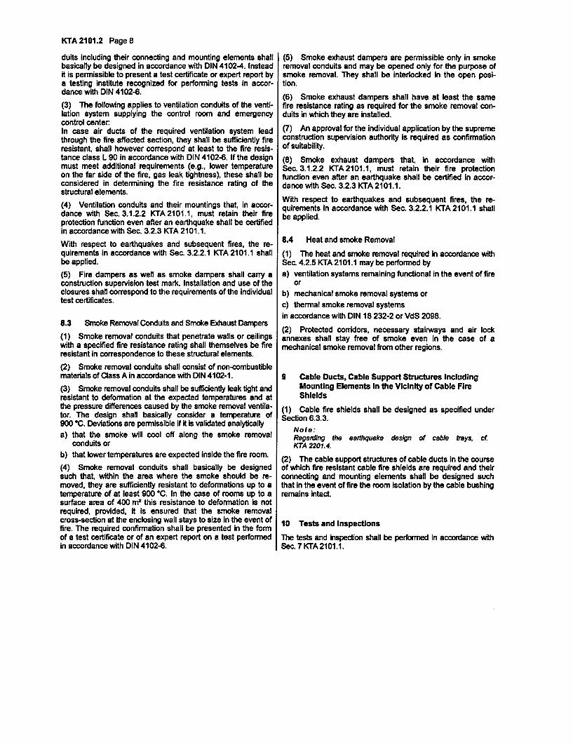
KTA 2101.2 Page 8
duits including their connecting and mounting elements shallbasically be designed in accordance with DIN 4102-4. Insteadit is permissible to present a test certificate or expert report bya testing institute recognized for performing tests in accor-dance with DIN 4102-6.
(3) The following applies to ventilation conduits of the venti-lation system supplying the control room and emergencycontrol centerIn case air ducts of the required ventilation system leadthrough the fire affected section, they shall be sufficiently fireresistant, shall however correspond at least to the fire resis-tance class L 90 in accordance with DIN 4102-6. If the designmust meet additional requirements (e.g., lower temperatureon the far side of the fire, gas leak tightness), these shall beconsidered In determining the fire resistance rating of thestructural elements.
(4) Ventilation conduits and their mountings that, in accor-dance with Sec. 3.1.2.2 KTA 2101.1, must retain their fireprotection function even after an earthquake shall be certifiedin accordance with Sec. 3.2.3 KTA 2101.1.
With respect to earthquakes and subsequent fires, the re-quirements in accordance with Sec. 3.2.2.1 KTA 2101.1 shallbe applied.
(5) Fire dampers as well as smoke dampers shall carry aconstruction supervision test mark. Installation and use of theclosures shall correspond to the requirements of the individualtest certificates.
8.3 Smoke Removal Conduits and Smoke Exhaust Dampers
(1) Smoke removal conduits that penetrate walls or ceilingswith a specified fire resistance rating shall themselves be fireresistant in correspondence to these structural elements.
(2) Smoke removal conduits shall consist of non-combustiblematerials of Class A in accordance with DIN 4102-1.
(3) Smoke removal conduits shall be sufficiently leak tight andresistant to deformation at the expected temperatures and atthe pressure differences caused by the smoke removal ventila-tor. The design shall basically consider a temperature of900 'C. Deviations are permissible if it is validated analyticallya) that the smoke will cool off along the smoke removal
conduits orb) that lower temperatures are expected inside the fire room.
(4) Smoke removal conduits shall basically be designedsuch that, within the area where the smoke should be re-moved, they are sufficiently resistant to deformations up to atemperature of at least 900 'C. In the case of rooms up to asurface area of 400 n2 this resistance to deformation is notrequired, provided, it is ensured that the smoke removalcross-section at the enclosing wall stays to size in the event offire. The required confirmation shall be presented in the formof a test certificate or of an expert report on a test performedin accordance with DIN 4102-8.
(5) Smoke exhaust dampers are permissible only in smokeremoval conduits and may be opened only for the purpose ofsmoke removal. They shall be interlocked in the open posi-tion.
(6) Smoke exhaust dampers shall have at least the samefire resistance rating as required for the smoke removal con-duits in which they are installed.
(7) An approval for the individual application by the supremeconstruction supervision authority is required as confirmationof suitability.
(8) Smoke exhaust dampers that, in accordance withSec. 3.1.2.2 KTA 2101.1, must retain their fire protectionfunction even after an earthquake shall be certified in accor-dance with Sec. 3.2.3 KTA 2101.1.
With respect to earthquakes and subsequent fires, the re-quirements in accordance with Sec. 3.2.2.1 KTA 2101.1 shallbe applied.
8.4 Heat and smoke Removal
(1) The heat and smoke removal required in accordance withSec. 4.2.5 KTA 2101.1 may be performed bya) ventilation systems remaining functional in the event of fire
orb) mechanical smoke removal systems orc) thermal smoke removal systemsin accordance with DIN 18 232-2 or VdS 2098.
(2) Protected corridors, necessary stairways and air lockannexes shall stay free of smoke even in the case of amechanical smoke removal from other regions.
9 Cable Ducts, Cable Support Structures IncludingMounting Elements In the Vicinity of Cable FireShields
(1) Cable fire shields shall be designed as specified underSection 6.3.3.
Note:Regarding the earthquake design of cable brays, cf.KTA 2201.4.
(2) The cable support structures of cable ducts in the courseof which fire resistant cable fire shields are required and theirconnecting and mounting elements shall be designed suchthat In the event of fire the room Isolation by the cable bushingremains intact.
10 Tests and Inspections
The tests and inspection shall be performed in accordance withSec. 7 KTA 2101.1.
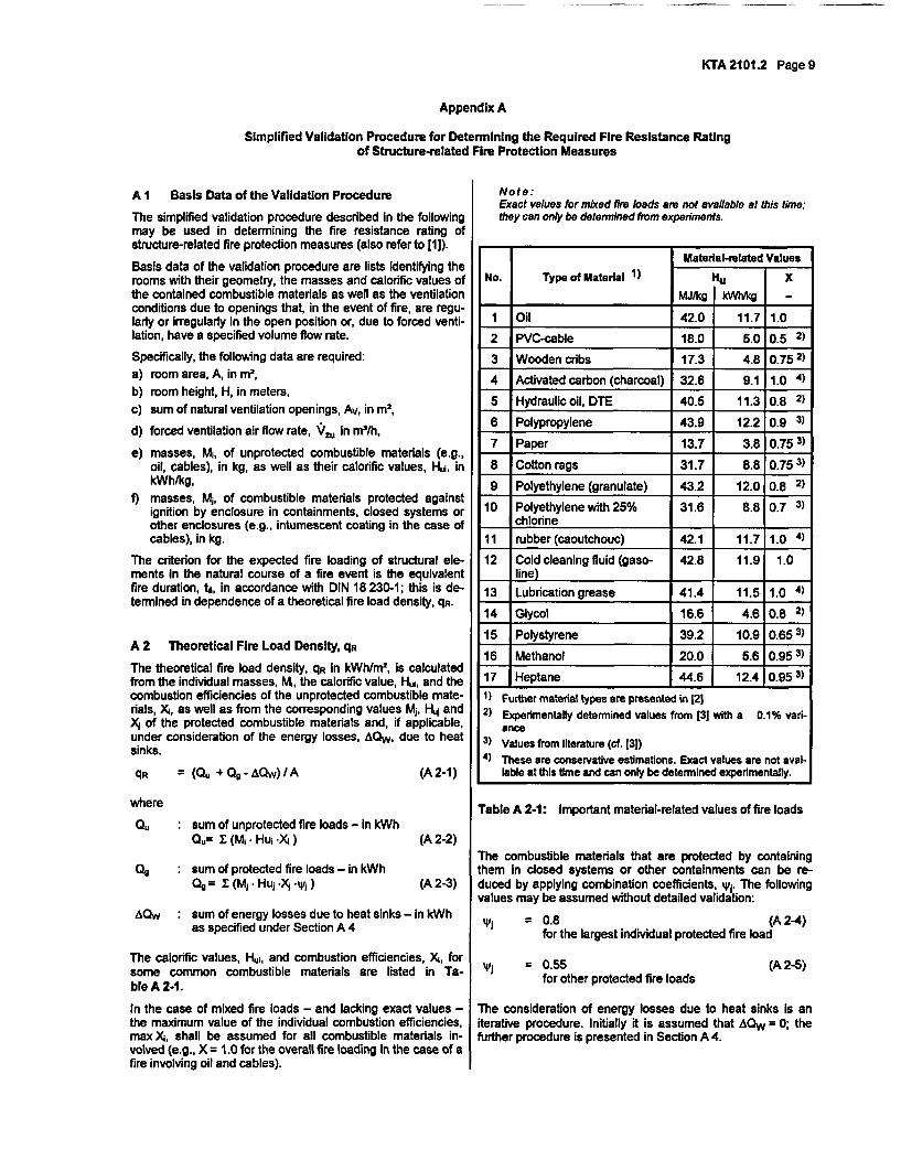
KTA 2101.2 Page 9
Appendix A
Simplified Validation Procedure for Determining the Required Fire Resistance Ratingof Structure-related Fire Protection Measures
A I Basis Data of the Validation Procedure
The simplified validation procedure described in the followingmay be used in determining the fire resistance rating ofstructure-related fire protection measures (also refer to [1]).
Basis data of the validation procedure are lists Identifying therooms with their geometry, the masses and calorific values ofthe contained combustible materials as well as the ventilationconditions due to openings that, in the event of fire, are regu-larly or Irregularly in the open position or, due to forced venti-lation, have a specified volume flow rate.
Specifically, the following data are required:a) room area, A, in m2,
b) room height, H, in meters,c) sum of natural ventilation openings, Av, in m2
,
d) forced ventilation air flow rate, V,, in m2/h,
e) masses, Mi, of unprotected combustible materials (e.g.,oil, cables), in kg, as well as their calorific values, Hui, inkWh/kg,
f) masses, Mj, of combustible materials protected againstignition by enclosure in containments, closed systems orother enclosures (e.g., intumescent coating in the case ofcables), in kg.
The criterion for the expected fire loading of structural ele-ments in the natural course of a fire event is the equivalentfire duration, ts, in accordance with DIN 18 230-1; this is de-termined in dependence of a theoretical fire load density, qR.
A 2 Theoretical Fire Load Density, qR
The theoretical fire load density, qR in kWh/i 2, is calculatedfrom the individual masses, Mi, the calorific value, Hu, and thecombustion efficiencies of the unprotected combustible mate-rials, Xi, as well as from the corresponding values Mj, Huj andX; of the protected combustible materials and, if applicable,under consideration of the energy losses, AQw, due to heatsinks.
Note:&act values fbr mixed fire loads are not available at this time;they can only be determined frm experiments.
Material-related ValuesNo. Type of Material 1) Hu X
MJ/kg kWihg -
1 Oil 42.0 11.7 1.0
2 PVC-cable 18.0 5.0 0.5 2)
3 Wooden cribs 17.3 4.8 0.75 2)
4 Activated carbon (charcoal) 32.8 9.1 1.0 4)
5 Hydraulic oil, DTE 40.5 11.3 0.8 2)
6 Polypropylene 43.9 12.2 0.9 3)
7 Paper 13.7 3.8 0.75 3)
8 Cotton rags 31.7 8.8 0.75 3)
9 Polyethylene (granulate) 43.2 12.0 0.8 2)
10 Polyethylene with 25% 31.6 8.8 0.7 3)I chlorine
11 rubber (caoutchouc) 42.1 11.7 1.0 4)
12 Cold cleaning fluid (gaso- 42.8 11.9 1.0__ _ line)_ _ _ _
13 Lubrication grease 41.4 11.5 1.0 4)
14 Glycol 16.6 4.6 0.8 2)
15 Polystyrene 39.2 10.9 0.65 3)
16 Methanol 20.0 5.6 0.95 3
17 Heptane 44.6 12.4 0.95 3)
1) Further material types are presented in [212) Experimentally determined values from [3] with a 0.1% vari-
ance3) Values from literature (cf. [3])4) These are conservative estimations. Exact values are not avai-
lable at this time and can only be determined experimentally.qR = (Qu + O- AQw)/A (A 2-1)
where
Ou : sum of unprotected fire loads - in kWhQu= v (M. - Hui .X )
49 : sum of protected fire loads - in kWhQ = z(Mj Hu1.X.Wj )
(A 2-2)
(A 2-3)
Table A 2-1: Important material-related values of fire loads
The combustible materials that are protected by containingthem in dosed systems or other containments can be re-duced by applying combination coefficients, yi. The followingvalues may be assumed without detailed validation:
qu = 0.8 (A 2-4)for the largest individual protected fire load
AQw : sum of energy losses due to heat sinks - in kWhas specified under Section A 4
The calorific values, Hui, and combustion efficiencies, X, forsome common combustible materials are listed in Ta-ble A 2-1.
In the case of mixed fire loads - and lacking exact values -the maximum value of the individual combustion efficiencies,max ), shall be assumed for all combustible materials in-volved (e.g., X = 1.0 for the overall fire loading in the case of afire involving oil and cables).
= 0.55for other protected fire loads
(A 2-5)
The consideration of energy losses due to heat sinks is aniterative procedure. Initially it is assumed that AQW = 0; thefurther procedure is presented in Section A 4.
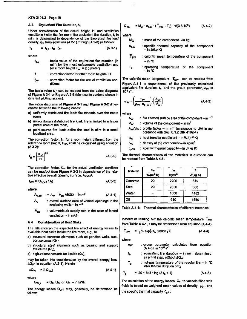
KTA 2101.2 Page 10
A 3 Equivalent Fire Duration, to
Under consideration of the actual height, H, and ventilationconditions inside the fire room, the equivalent fire duration, tU inmin, is determined in dependence of the theoretical fire loaddensity, qR, from equations (A 2-1) through (A 2-3) as follows:
Qwi =Mw cpw (Tsw- T0) 11(3.6106) (A 4-2)
to = tA, fH fAV (A 3-1)
wheretoo :basic value of the equivalent fire duration (in
min) for the most unfavorable ventilation andfor a room height Href = 2.5 meters
fH :correction factor for other room heights, H
fAv : correction factor for the actual ventilation con-ditions
The basic value ta,o can be readout from the value diagramsof Figure A 3-1 or Figure A 3-2 (identical in content, shown indifferent plotting scales).
The value diagrams of Figure A 3-1 and Figure A 3-2 differ-entiate between the following cases:a) uniformly distributed fire load: fire extends over the entire
room,b) non-uniformly distributed fire load: fire is limited to a larger
partial area of the room,c) point-source fire load: entire fire load is afire in a small
localized area.
The correction factor, fH, for a room height different from thereference room height, Hre, shall be calculated using equation(A 3-2):
whereMw :mass of the component - in kg
cp.w : specific thermal capacity of the component- in JI(kg K)
Tsw : calorific mean temperature of the component
- in 'C
To : operating temperature of the component- In @C
The calorific mean temperature, TSW, can be readout from
Figure A 4-1 in dependence of the previously calculatedequivalent fire duration, to, and the group parameter, ow inI b-s vf
(,_ aWa' .w cp'W)_(Vj (A 4-3)
whereAw
VwAW/Vw
aw
PwcP'w
: fire affected surface area of the component - in m2
: volume of the component - in m3
: profile factor - in m-1 (analogous to UIA in ac-cordance with Sec. 6.1.2 DIN 4102-4)
: heat transfer coefficient - in WI(m2 -K)
: density of the component - in kg/M3
: specific thermal capacity - in J/(kg K)
[ H, ]fH = [- (A 3-2) The thermal characteristics of the materials in question canbe readout from Table A 4-1.
The correction factor, fAx, for the actual ventilation conditioncan be readout from Figure A 3-3 in dependence of the rela-tive effective overall opening surface, Av,effIA:
fAv = f(Aveff I A) (A 3-3)
where
Av eff Av + Vu /6000 - in m2 (A 3-4)
Av : overall surface area of vertical openings In theenclosing walls - in m2
volumetric air supply rate in the case of forced
ventilation - in m3/h
A 4 Consideration of Heat Sinks
The influence on the expected fire effect of energy losses toavailable heat sinks inside the fire room, e.g., toa) structural concrete elements such as partition walls, sup-
port columns (QB),b) structural steel elements such as bearing and support
structures (Qs),c) high-volume vessels for liquids (QF),
may be taken into consideration by the overall energy loss,AQW, in equation (A 2-1). Herein
AQw = Y Qwi (A 4-1)
whereQWi = , QS or OF -in kWh
Material aw PW cWI(m2.K) kg/m 3 JI(kg K)
Concrete 20 2200 879
Steel 20 7850 600
Water - 1000 4182
Oil - 910 1880
Table A 4-1: Thermal characteristics of different materials
Instead of reading out the calorific mean temperature Tswfrom Table A 4-1, it may be determined from equation (A 4-4)
Tsw =Tgl-exp(-sw x60xta)] (A 4-4)
whererw : group parameter calculated from equation
(A 4-5) in 104 s-1
ta : equivalent fire duration - in min, determined,as a first step, without AQw
Tg : hot-gas temperature of the regular fire - in 0Cafter the fire duration of tg
Tg = 20+ 345 * log (8-4 1) (A 4-5)
The calculation of the energy losses, QF, to vessels filled with
fluids is based on weighted mean values of density, AF, and
the specific thermal capacity dPF:The energy losses QW i may, generally, be determined asfollows:
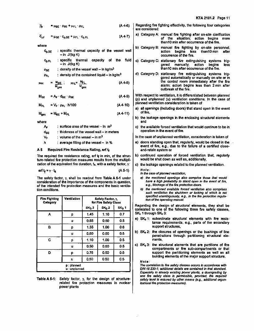
KTA 2101.2 Page 11
fF 1± BE 'PBE +IIFL -PPL
CPF = lPBE CpBE + PFL' CpFL
(A 4-6) Regarding fire fighting effectivity, the following four categoriesI are considered:
(A 4-7) a) Category A:
whereCPBE : specific thermal capacity of the vessel wall
- in J/(kg K)
CPFL : specific thermal capacity of the fluid-in J(kg K)
b) Category B:
c) Category C:
d) Category D:
manual fire fighting after on-site clarificationof the situation; action begins morethan1O min after occurrence of the fire.manual fire fighting by on-site personnel;action begins less thanlO min afteroccurrence of the fire.
stationary fire extinguishing systems trig-gered manually; action begins lessthan 10 min after occurrence of the fire.stationary fire extinguishing systems trig-gered automatically or manually on site or inthe control room immediately after the firealarm; action begins less than 2 min afteroutbreak of the fire.
PBE
PFL
: density of the vessel wall - in kg/m3
: density of the contained liquid - in kg/m3
MaE = MBE; MFL= MFLMges Mges
(A 4-8)
MBE = AF dBE 'PBE (A 4-9)
MFL = VF -pFL h/100 (A 4-10)
Mges = MBE + MFL
where
(A 4-11)
AF
dBE
VF
: surface area of the vessel - in m2
: thickness of the vessel wall - in meters: volume of the vessel - in m3
h : average filling of the vessel - in %
A 5 Required Fire Resistance Rating, erf t
The required fire resistance rating, erf tf in min, of the struc-ture-related fire protection measures results from the multipli-cation of the equivalent fire duration, to, with a safety factor, y:
erf tf = , to (A 5-1)
The safety factor, y, shall be readout from Table A 5-1 underconsideration of the importance of the components in question,of the intended fire protection measures and the basic ventila-tion conditions.
Fire Fighting Ventilation Safety Factor, y,Category for Fire Safety Class
SKb 3 SKb 2 SKb 1
A p 1.45 1.10 0.7
u 0.85 0.50 0.5
B p 1.35 1.00 0.6
u 0.80 0.50 0.5
C P 1.10 1.00 0.5
u 0.50 0.50 0.5
D P 0.75 0.50 0.5
u 0.50 0.50 0.5
p: plannedu : unplanned
With respect to ventilation, it is differentiated between planned(p) and unplanned (u) ventilation conditions. In the case ofplanned ventilation consideration is taken ofa) all openings (including doors) that stand open in the event
of fire,b) the leakage openings in the enclosing structural elements
andc) the available forced ventilation that would continue to be in
operation in the event of fire.
In the case of unplanned ventilation, consideration is taken ofa) doors standing open that, regularly, would be dosed in the
event of fire, e.g., due to the failure of a certified close-and-retain system or
b) continued operation of forced ventilation that, regularlywould be shut down as well as, additionally,
c) the leakage openings related to the planned ventilation.Note:In the case of planned ventilation,a) the mentioned openings also comprise those that would
have a high probability to stand open in the event of fire,e.g., blockage of the fir protection doors.
b) the mentioned available forced ventilation also comprisessuch ventilation the shutdown or locking of which is notspecified unambiguously, e.g., in the fire protection regula-tion of the operating manual.
Regarding the design of structural elements, they shall becorrelated to one of the following three fire safety classes,SKb 1 through SKb 3:
a) SKb 1: subordinate structural elements with fire resis-tance requirements, e.g., parts of the secondarysupport structures,
b) SKb 2: the closures of openings or the bushings of linepenetrations through partitioning structural ele-ments,
c) SKb 3: the structural elements that are partitions of firecompartments or fire sub-compartments or thatsupport the partitioning elements as well as allbuilding elements of the major support structure.
Note:The correlation to fire safety classes occurs in accordance withDIN 18 230-1; additional details are contained in that standard.Especially in already existing power plants, a downgrading byone fire safety class is permissible, provided, the requiredsafety level is ensured by other means (e.g., additional organ-izational fire protection measures).
Table A 5-1: Safety factor, y, for the design of structure-related fire protection measures in nuclearpower plants
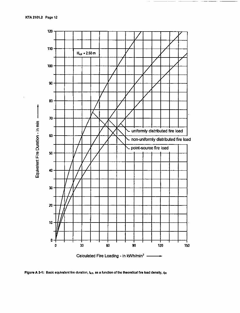
KTA 2101.2 Page 12
120 :rziziziv Tu111IVl IIZ I IzII I / /
110 ej = 2.50 rnI;I- t _
100- ___-,;Z __ 7 f__ I -- AZ fF
8- _ _ __g -TZ r- _ __7
0
0
6-.C_0)
0*w
uV /_j~/ _ L , ,j\ J \ uniformly distributed fire load
60
50
40
30
20
10
0
/ / 00,/\ I\ non-uniformly distributed fire load
_ _ T _ _ o <point-source fire load
-- _ I I I
1 Z V __ I I I_A r1 I I I
/Z V/II0 30 60 90 120 150
Calculated Fire Loading - in kWh/min2
Figure A 3-1: Basic equivalent fire duration, ta,o, as a function of the theoretical fire load density, qR
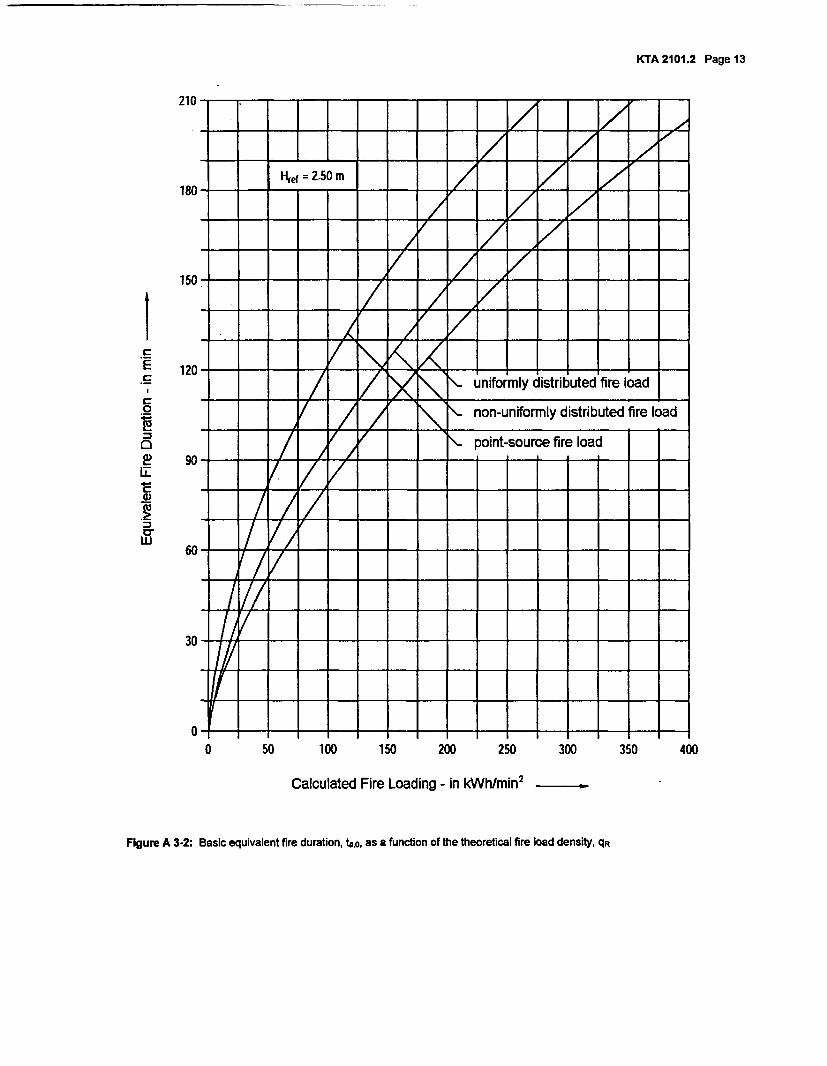
KTA 2101.2 Page 13
.EL
C0
20
C
0)
w
0 50 100 150 200 250 300 350 400
Calculated Fire Loading - in kWh/min2
Figure A 3-2: Basic equivalent fire duration, too, as a function of the theoretical fire load density, qR
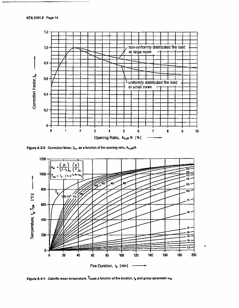
KTA 2101.2 Page 14
1",I 1 I - T - f - I - I - - ¶ - I -t - r - I - - - - I - I - I - I - I 1�
I I I I I I I I
1,0 )-._ , -- = = - fon-uniformly distributed fire load
= =Z = - ~-7 or large room . I I I= - _ _ ! 1 1 1 1
; _I I 1 1 1--. II an
0
._
W
LL
0
00
0,6-uniformly distributed fire load
…___ _ or smallroom
0A- -
0O-- - -= - = = =
z
0 1 2 3 4 5 6 7
Opening Ratio, Av~e, A [% -
8 9 10
Figure A 3-3: Correction factor, fA, as a function of the opening ratio, Av.,f/A
----l
i.-
La;
E0)
1 2 0 0 - I_ __I
ow
10001
Xg gg k125
800- - 10
6 -
0 20 40 60 80 100 120 140 160 180 200
Fire Duration, 4 Imini
Figure A 4-1: Calorific mean temperature, TsAas a function of fire duration, t and group parameter aw
KTA 2101.2 Page 15
Appendix B
Regulations Referred to In this Safety Standard
Regulations referred to in this safety standard are only valid in the version cited below. Regulations which are referred to withinthese regulations are valid only in the version that was valid when the latter regulations were established or issued.
KTA 2101.1 (12/00) Fire protection in nuclear power plants; Part 1: Basic requirements
KTA 2201.1 (06/90) Design of nuclear power plants against seismic events; Part 1: Principles
KTA 2201.4 (06/90) Design of nuclear power plants against seismic events; Part 4: Requirements for the proceduresfor verifying the safety of mechanical and electrical components against earthquakes(amended by BAnz. No. 115 of June 25, 1996)
KTA 3402 (11/76) Air locks through the containment vessel of nuclear power plants - Personnel locks
KTA 3403 (10/80) Cable penetrations through the reactor containment vessel
KTA 3601 (06/90) Ventilation and air filtration systems in nuclear power plants
KTA 3904 (09/88) Control room, emergency control room and local control stations in nuclear power plants
DIN 4102-1 (05/98) Fire behaviour of building materials and building components - Part 1: Building materials;Concepts, requirements and tests
DIN 4102-1 (08/98) Corrigenda to DIN 4102-1:1998-05
DIN 4102-2 (09/77) Fire behaviour of building materials and building components; Building components; definitions,requirements and tests
DIN 4102-3 (09/77) Fire behaviour of building materials and building components; Fire walls and non-load-bearingexternal walls; Definitions, requirements and tests
DIN 4102-4 (03/94) Fire behaviour of building materials and building components; synopsis and application ofclassified building materials, components and special components
DIN 4102-6 (09/77) Fire behaviour of building materials and building components; Ventilation ducts; Definitions,requirements and tests
DIN 4102-7 (07/98) Fire behaviour of building materials and building components - Part 7: Roofing; definitions,requirements and testing
DIN 4102-9 (05/90) Fire behaviour of building materials and elements; Seals for cable penetrations; Concepts,requirements and testing
DIN 4102-11 (12/85) Fire behaviour of building materials and building components; Pipe encasements, pipe bushings,service shafts and ducts, and barriers across inspection openings; Terminology, requirementsand testing
DIN 14 090 (06/77) Areas for the fire brigade on premises
DIN 18 095-1 (10/88) Smoke control doors; Concepts and requirements
DIN 18 164-1 (08/92) Rigid cellular plastics insulating building materials; Thermal insulating materials
DIN 18 164-2 (03/91) Rigid Cellular plastics insulating building materials; Polystyrene foam impact sound insulatingmaterials
DIN 18 232-2 (11/89) Structural fire protection in industrial buildings; Smoke and heat control installations; Design,construction, performance and installation of smoke vents
DIN 52 460 (05/91) Sealing and glazing; Terms
DIN VDE 0101 (05/89) Erection of power installations with rated voltages exceeding I kV
VdS 2098 (05/90) Heat and smoke removal systems; Guidelines for design and installation
KTA 2101.2 Page 16
Literature
11] Hosser, D. et. al.Untersuchungen zur Regelfahigkeit von brandschutztechnischen Nachweisen im Rahmen von KTA 2101.2(Abschlullbericht). Schriftenreihe Reaktorsicherheit und Strahlenschutz, BMU-1996-467, im Auftrag des Bundesmi-nisteriums fOr Umwelt, Naturschutz und Reaktorsicherheit, Februar 1996, ISSN 0724-3316Examining the possibilities for establishing standards regarding the verification of fire protection measures within theframework of KTA 2101.2 (Final Report)
[2] Schneider, U.Festlegung von Brandszenarien fOr den Entwurf von Gebauden und fOr die Risikobetrachtung. VdS-Fachtagung .In-genieurmailige Verfahren im Brandschutt am 25. und 26. April 1995 in Koln.Specification of fire scenarios for the design of buildings and for the risk assessments
[3] Hosser, D.; Blume, G.; Siegfried, W.; Will, J.Untersuchungen zur Regelfahigkeit von brandschutztechnischen Nachweisen im Rahmen von KTA 2101.2 - Ermitt-lung effektiver Heizwerte; Untersuchung im Auftrag des BMU, Aktenzeichen SR 2226-81225-UA-1457Examining the possibilities for establishing standards regarding the verification of fire protection measures within theframework of KTA 2101.2 - Determining actual calorific values
Safety Standardsof theNuclear Safety Standards Commission (KTA)
KTA 2101.3 (12/2000)
Fire Protection in Nuclear Power PlantsPart 3: Fire Protection of Mechanical and Electrical Plant
Components
(Brandschutz in KernkraftwerkenTeil 3: Brandschutz an maschinen- und elektrotechnischen
Anlagen)
If there is any doubt regarding the information contained in this translation, the German wording shall apply.
Editor:KTA-Geschaeftsstelle c/o Bundesamt fuer Strahlenschutz (BfS)Willy-Brandt-Str. 5 * 38226 Salzgitter * GermanyTelephone +49-(0)1888/333-(0)1621 * Telefax +49-(0)1888/333-1625
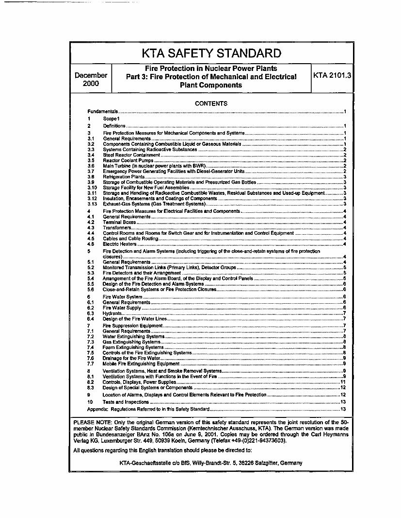
KTA SAFETY STANDARDFire Protection in Nuclear Power Plants
December Part 3: Fire Protection of Mechanical and Electrical KTA 2101.32000 Plant Components
CONTENTSFundamentals ......... 1
I Scopel2 Definitions ................................................................... 1
3 Fire Protection Measures for Mechanical Components and Systems ................................................................... 13.1 General Requirements ................................................................... 13.2 Components Containing Combustible Liquid or Gaseous Materials ................................................................... 13.3 Systems Containing Radioactive Substances ................................................................... 23.4 Steel Reactor Containment ................................................................... 23.5 Reactor Coolant Pumps ................................................................... 23.6 Main Turbine (in nuclear power plants with BWR) ................................................................... 23.7 Emergency Power Generating Facilities with Diesel-Generator Units .................................................................. 23.8 Refrigeration Plants ................................................................... 33.9 Storage of Combustible Operating Materials and Pressurized Gas Bottles ................................................................ 33.10 Storage Facility for New Fuel Assemblies .................................................................................. 33.11 Storage and Handling of Radioactive Combustible Wastes, Residual Substances and Used-up Equipment .............. 33.12 Insulation, Encasements and Coatings of Components ................................................................................... 33.13 Exhaust-Gas Systems (Gas Treatment Systems) ................................................................................... 3
4 Fire Protection Measures for Electrical Facilities and Components Measures.for.Electrical...........and.Components..44.1 ...................................................................General Requirements.44.2 T r n l o e .............................................................Terminal Boxes.44.3 T a f r r ............. ................ ..... .. .... ........ ....... .......Transformers.44.4 Control Rooms and Rooms for Switch Gear and for Instrumentation and Control Equipment .44.5 ...................................................................Cables and Cable Routing.44.6 Ee . c e t s............................................................Electric Heaters.45 Fire Detection and Alarm Systems (including triggering of the close-and-retain systems of fire protection
closures).45.1 G n a R u e n ..................................................General Requirements.45.2 Monitored Transmission Links (Primary Links), Detector Groups.m .. . .s), D.......Groups.55.3 .........................................................Fire Detectors and their Arrangement.55.4 Arrangement of the Fire Alarm Board, of the Display and Control Panels .65.5 Design of the Fire Detection and Alarm Systems S y s t e m s..65.6 ........................................................Close-and-Retain Systems or Fire Protection Closures .6
6 Fr W e S t ...................................................Fire W ater System.66.1 G n a R u e n ..................................................General Requirements.66.2 Fr W e S p ...................................................Fire W ater Supply.66.3 H r t . . . . . . . . . . . . . . . . . . . . . . . . . . . . . . . . . . . . . . . . . . . . . . . . . . . . ..Hydrants.76.4 D s n fh F e ae L e ..............................................Design of the Fire Water Lines.77 Fr S p s o E u m t...............................................Fire Suppression Equipment.77.1 G n a R u e n ..................................................General Requirements.77.2 WtE.gsiSsm...............................................Water Extinguishing Systems.87.3 G s xn i i S se ................................................Gas Extinguishing Systems387.4 F a E n u hn S t s...............................................Foam Extinguishing Systems.87.5 .........................................................Controls of the Fire Extinguishing Systems.87.6 Da a frh F e a r...............................................Drainage for the Fire Water.97.7 Mobile Fire Extinguishing Equipment .9
8 Ventilaion Sytems, eat.andSmoke.emovalSystems............Ventilation Systems, Heat and Smoke Removal Systems.98.1 Ventilation Systems with Functions In the Event of Fire E v ent. o f . F i r e..98.2 Controls, Displays, Power Supplies .118.3 Design of Special Systems or Components. .12
9 Location of Alarms, Displays and Control Elements Relevant to Fire Protection. .and.Control.Elements.Relevant.to..re..........12
10 .........................................................Testsand Inspe tions 13
Appendix: Regulations Referred to In this Safety Standard ......................................... 13
PLEASE NOTE: Only the original German version of this safety standard represents the joint resolution of the 50-member Nuclear Safety Standards Commission (Kemtechnischer Ausschuss, KTA). The German version was madepublic in Bundesanzeiger BAnz No. 106a on June 9, 2001. Copies may be ordered through the Carl HeymannsVerlag KG, Luxemburger Str. 449, 50939 Koeln, Germany (Telefax +49-(0)221-94373603).
All questions regarding this English translation should please be directed to:
I
KTA-Geschaeftsstelle c/o BfS, Willy-Brandt-Str. 5, 38226 Salzgitter, Germany
KTA 2101.3 Page 4
Comments by the editor:
Taking into account the meaning and usage of auxiliary verbs in the German language, in this translation the following agree-ments are effective:
shall
shall basically
shall normally
should
may
indicates a mandatory requirement,
is used in the case of mandatory requirements to which specific exceptions (and only thosel) arepermitted. It is a requirement of the KTA that these exceptions - other than those in the case of shallnormally - are specified in the text of the safety standard,
indicates a requirement to which exceptions are allowed. However, the exceptions used shall besubstantiated during the licensing procedure,
indicates a recommendation or an example of good practice,
indicates an acceptable or permissible method within the scope of this safety standard.
KTA 2101.3 Page 1
Fundamentals
(1) The safety standards of the Nuclear Safety StandardsCommission (KTA) have the task of specifying those safetyrelated requirements which shall be met with regard to precau-tions to be taken in accordance with the state of science andtechnology against the damage arising from the constructionand operation of the facility (Sec. 7 para. 2 subpara. 3 AtomicEnergy Act), in order to attain the protection goals specified inthe Atomic Energy Act and Radiological Protection Ordinance(StrlSchV) and which are further detailed in 'Safety Criteria forNuclear Power Plants' and in 'Guidelines for the Assessment ofthe Design of PWR Nuclear Power Plants against Incidentspursuant to Sec. 28 para. 3 of the Radiological Protection Ordi-nance (StrlSchV) - Incident Guidelines'.
(2) Criterion 2.7 'Fire and Explosion Protection" of the SafetyCriteria for Nuclear Power Plants specifies that protectionmeasures shall be taken against fires in nuclear power plants.In accordance with Table II of the Incident Guidelines, plant-internal fires belong to those design basis accidents (incidents)for which precautionary plant engineering measures must betaken and which on account of these measures do not have anyrelevance with respect to radiological effects on the environ-ment.The details of these precautionary measures with respect tomechanical and electrical equipment-related fire protectionmeasures are specified in this safety standard.
(3) In setting up this safety standard it is assumed that thebuilding codes, fire protection laws and fire protection regula-tons of the individual German states (Lander), the WorkplaceOrdinance, the German Accident Prevention Regulations of thetrade unions, the VdS guidelines and other regulations underpublic law are met. If the specifics of the nuclear power plantrequire deviations from Laws, ordinances or other regulationsunder public law or from the German Accident PreventionRegulations (UVV), then the particular deviations and excep-tions shall be handled on an individual basis in accordance withthe procedures specified in those individual regulations.
(4) This safety standard KTA 2101.3 supplements the safetystandardsKTA2101.1 Fire protection in nuclearpowerplants;
Part 1: Basic requirementsKTA 2101.2 Fire protection in nuclear power plants;
Part 2: Fire protection of structural plant components
by additional requirements that apply specifically to the fireprotection of mechanical and electrical plant components innuclear power plants. It is closely connected to the structuralrequirements specified in safety standard KTA 2101.2, inparticular to those specified for ventilation systems as well ascable and pipe penetration bushings.
Note:Additional relevant KTA safety standards are listed InKTA 2101.1.
1 Scope
This safety standard applies to nuclear power plants with lightwater reactors.
It applies to the protection from building-internal and building-external fires, in particular, with respect toa) plant components the safety function of which are neces-
sary to meet the protection goals on which the Safety Cri-teria are based, i.e.,aa) control of reactivity,ab) cooling of fuel assemblies,ac) confinement of radioactive substances andad) limitation of radiation exposure,
b) the structural plant components which enclose these plantcomponents and
c) the plant personnel.Note:These stnuctural plant components include, e.g., the reactor build-ing, the reactor auxiliary building, the nuclear services building aswell as the structural plant components of the service cooing watercircuits, the emergency standby bu,7ding, the emergency feed waterbuilding, the switch gear building, the turbine bulding of boiling wa-ter reactors, the emergency power generator building, the pipingand cable ducts between the aforementioned buildings.
2 DefinitionsNote:Additional definitions are given in safety standards KTA 2101.1and KTA 2101.2.
(1) Mechanical smoke removal
Mechanical smoke removal is based on exhausts equippedwith ventilators.
(2) Thermal smoke removal
Thermal smoke removal is based on exhausts that work bythermal convection.
(3) Heat and smoke removal systems
Heat and smoke removal systems (HSR) are the entirety of allequipment that normally and predominantly serve as exhaustfor the smoke and hot combustion gases in the event of fire.This includes mechanical and thermal smoke removal.
3 Fire Protection Measures for Mechanical Compo-nents and Systems
3.1 General Requirements
(1) An analytical confirmation with regard to the loadingfrom external events is required for those fire protectionequipment of mechanical components that, in the course ofthe individual nuclear licensing procedure, are specified inconjunction with the fire protection concept.
(2) Oil supplies shall be designed such that possible leak-age oil will not come into contact with plant components hav-ing a surface temperature higher than 200 "C. The heat insu-lation in the vicinity of oil supplies shall be designed such thatautoxidation from leakage oil seeping Into the heat insulationis prevented.
(3) Insofar as the measures specified under Sections 3.2through 3.13 cannot be applied to the extent needed to en-sure the required protection in the event of fire, additionalmeasures regarding fire detection (e.g., by installing additionalfire detectors) as well as regarding fire fighting (e.g., by install-ing stationary fire extinguishing systems) shall be specified.
3.2 Components Containing Combustible Liquid or Gase-ous Materials
Note:Special reference Is made to VBG 61 (Gases), to the TechnicalStandards for Flammable Liquids (TRbF), Technical Standards forPressure Vessels (TRB), Technical Standards for PressurizedGases (TRG) and to Technical Standards for Acetylene Facilitiesand Calcium Carbide Depots (TRAC). General requirements arecontained, e.g., in VGB Guideline "Fire Protection in NuclearPower Plants' (VGB-R 108). Protective measures against explo-sions are specified in safety standard KTA 2103.
(1) Only non-combustible materials shall basically be used.Exceptions are permissible in the case of sealants and gas-kets, provided, they are protected against direct flames in the
KTA 2101.3 Page 2
event of fire. Combustible hoses shall normally be completelysurrounded by metal sheathing.
(2) The systems containing flammable liquid or gaseousmaterials shall normally be provided equipment for leakagedetection, e.g., filling level monitors in the case of liquid mate-rials and pressure monitors in the case of gaseous materials,and, if applicable, for the draining off of leakages.
(3) Vessels containing larger amounts of flammable liquidsshall be provided with collecting facilities. The volume of thecollecting facilities shall be specified under consideration of themaximum possible non-isolatable leakage amount of the largestindividual vessel and, in the case of the presence of a stationaryfire extinguishing system, also of the accumulated fire suppres-sant; measures shall be taken to enable a controlled draining offof the accumulated fire suppressant and liquid leakage.
(4) Combustible materials escaping from safety valves shallbe safely drained or dissipated off.
(5) Any hot component parts shall basically be avoided inthe vicinity of components containing combustible orcombustion supporting materials. If this is not possible fortechnical reasons, measure shall be taken to prevent self-ignition of the leakages (e.g., insulation, concentric guardpipe, encapsulation, air exhaust).
(6) It is not permissible to use cutting ring fittings for pres-sure retaining pipes containing flammable liquid materials.
3.3 Systems Containing Radioactive Substances
The necessity for a fire protection of pipes and componentscontaining radioactive substances shall be specified in eachindividual case on the basis of the inventory of radioactivity.
3.4 Steel Reactor Containment
(1) The integrity of the reactor containment in the event of fireshall be ensured. Therefore, larger fire loads in the direct vicinityof the containment wall shall basically be avoided. Exceptionsare such fire loads that are protected by suitable structure-related or equipment-related fire protection measures. In casesuch measures cannot be applied, other requirements shall bespecified in each individual case, e.g., protective coating of thecables in the vicinity of cable penetrations.
(2) The measures specified under para. I shall also ensurethat no fire spreading occurs on account the influence fromdirect heat or thermal radiation on the other side of the con-tainment wall.
(3) The air locks and air lock annexes shall be kept free ofany fire loads that are not required for the operation of thelocks or for the purpose of personnel protection.
Note:Requirements regarding the structural and other technical rneas-ures for air locks and air lock annexes are dealt with in safetystandard KTA 2102 (in preparation). Requirements regarding thearrangement of the functional controls is specified in Sec. 15.2KTA 3402 (Air locks through the containment vessel of nuclearpower plants - Personnel locks) and in Sec. 14.2 KTA 3409 (Airlocks through the containment vessel of nuclear power plants -Material locks).
(4) The function of safety-related actuators, valves andfittings shall be ensured such that even in the event of fire thenecessary safety-related measures can be taken to the re-quired extent.
Note:This applies, e.g., to the inside main steam isolation valves and tothe safety and relief valves of boiling water reactors (BWR), in or-der to ensure that an 'intentional pressure relief is possible evenin the event of fire.
3.5 Reactor Coolant Pumps
(1) In the case of an external oil supply, the oil amount inthe oil tank shall be monitored by suitable means. As soon asthe oil amount falls below a minimum value to be specifieddepending on the oil supply, the oil supply shall automaticallybe interrupted.
(2) In the case of reactor coolant pumps and associatedmotors are provided with an integrated oil supply, the pumpsshall be equipped with a collecting facility for the entire oilamount of the largest individual supply vessel.
(3) In the case of an Integrated oil supply with coolingequipment inside the oil vessel, the level in the oil vessel shallbe monitored. When the maximum permissible level isreached, the cooling water supply to the oil cooler shall beshut off.
(4) Sec. 3.2.2.1 KTA 2101.1 shall be taken into considera-tion in the design of the oil supply lines of the reactor coolantpumps against external events. This shall basically also applyto the oil tank including the auxiliary equipment. In the case ofan external oil tank, the oil tank including the auxiliary equip-ment in the same room does not need to be designed againstexternal events, provided, it is validated analytically that thestructural partitions of the fire sub-compartment of the oil tankcompartment will remain functional even after an externalevent and that the oil collection vessel is still leak tight.
Note:Requirements regarding the structural partitions of the fire sub-compartment of the oil tank are contained in safety standardKTA 2101.2.
(5) In the case of boiling water reactors with an external oilsupply, the design of the reactor coolant pumps shall incorpo-rate measures that will prevent an uncontrolled release of oil.
3.6 Main Turbine (in nuclear power plants with BWR)
(1) The pressurized oil supply lines including return linesshall be routed to and from the turbine deck in separatechannels.
(2) A flame retardant control medium in fluid group HFD inaccordance with VDMA 24317, or an equivalent fluid, shallnormally be used for the turbine control system.
Note:VGB-R 108 contains additional fire protection requirements.
3.7 Emergency Power Generating Facilities with Diesel-Generator Units
(1) The fuel oil storage tank of each redundancy shall belocated, and the fuel oil day tank of each redundancy shallbasically be located, in individual fire sub-compartments apartfrom the diesel generator units.
(2) The exhaust gas lines shall be insulated and encasedwith non-combustible building materials of Class A 1 in accor-dance with DIN 4102-1 such that the surface temperatureeven during continuous operation will not exceed 200 *C. Itshall be ensured that neither fuel oil nor lubrication oil willpenetrate into the Insulation.
(3) The fuel oil system and the lubrication oil system of thediesel motor shall be routed or insulated such that no leak-ages can come in contact with components the surface tem-peratures of which are above 200 *C. The fuel oil injectionlines shall be designed with a concentric guard pipe or with acomparable shielding.
(4) The pipe connections of fuel oil injection lines shall bemetallically sealing or of an equivalent design.
KTA 2101.3 Page 3
(5) Fuel or oil leakages from the diesel motor, from the fueloil day tank, fuel oil storage tank or supply lines shall be col-lected in, or drained into vats or vessels and shall be moni-tored and displayed. If applicable, a siphoning effect from thefuel oil tanks shall be taken into consideration.
3.8 Refrigeration Plants
(1) Non-combustible refrigerants shall normally be used.
(2) Insofar as combustible insulation materials are used, thefire protection measures specified under Section 3.12 shall beapplied.
3.9 Storage of Combustible Operating Materials and Pres-surized Gas Bottles
(1) It is not permissible to store combustible or combustionsupporting gases, e.g., oxygen, in the vicinity of safety-relatedplant components. The storage of combustible or combustionsupporting gases inside the controlled area shall be limited tothe amounts required for the individual task.
(2) The storage of flammable liquids or other combustible orcombustion supporting materials in the vicinity of safety-relatedplant components shall basically be avoided. This storage isonly permissible if a fire of the materials stored cannot endan-ger any of the safety-related plant components. The exceptionsare the diesel fuel required in accordance with KTA 3702 aswell as the operating materials contained in the systems.
(3) It is not permissible to store flammable liquids in hazardclasses Al, A2 and B in accordance with VbF together withother combustible or combustion supporting materials.
(4) In the case of storage of flammable liquids, means forthe collection of the maximum possible non-isolatable amountof leakage from the largest individual vessel shall be providedfor in the direct vicinity of the place of installation of this ves-sel; furthermore, means shall be provided to enable a con-trolled draining off of the accumulated fire suppressant andliquid leakage.
(5) No stationary pressurized gas bottles, even for non-flammable gases, may be installed in the vicinity of massivefire loads. Exempted are pressurized gas bottles for small fireextinguishing systems and for equipment protection systems.
3.10 Storage Facility for New Fuel Assemblies
(1) Neither pipe lines carrying combustible materials, norcables and power lines nor combustible materials not requiredfor the operation of the storage facility shall be led through, orstored in, the storage room.
(2) In the storage room only such fire suppressants shall beused for which the criticality analysis in accordance withSec. 3.1.2.1 para. 3 KTA 3602 has confirmed that they will notcause criticality. The permissible fire suppressants shall bespecified in the operating manual and listed at the entranceways to the storage room.
3.11 Storage and Handling of Radioactive CombustibleWastes, Residual Substances and Used-up Equipment
Note:Reference Is made to VdS 2199 'Fire protection In the storage fa-ciy and VdS 2218 'Guideline for the tire protection of storagefacilities for dangerous materials".
(1) Such materials shall be collected in non-combustibleand lockable containers. Flammable liquids shall be collectedseparately. The containers shall be marked with appropriatedanger symbols. The containers shall normally be stored in aventilated room until further treatment.
(2) When storing such materials, an impermissible releaseof radioactive materials shall be prevented even under con-sideration of the fact that autoxidation can lead to combustiblegases. Safety standard KTA 2103 shall be taken into accountif the creation of combustible gases cannot be precluded.
3.12 Insulation, Encasements and Coatings of Components
(1) The insulation of pipes and components shall basicallyconsist of non-combustible materials in building materialclass A in accordance with DIN 4102-1
(2) In the case of low-temperature insulations it is permissi-ble to use combustible foam isolation materials or combusti-ble auxiliary materials, provided,a) the insulation material is in building material class B 1 in
accordance with DIN 4102-1,b) the insulation material after installation
ba) is comparable to building materials in building materialclass B 1 in accordance with DIN 4102-1,
bb) is protected from direct flames by a sheet metal en-casement and
bc) it is proven that inside the insulation a sustained fire isnot possible.
(3) In the vicinity of possible leakages of flammable liquids,special measures shall be taken to prevent the penetration ofthese liquids into the insulation materials, e.g., by baffles orsheet metal encasements.
(4) The decontaminable coatings of components shall be atleast flame retardant in accordance with building materialclass B 1 of DIN 4102-1 and, with regard to the developmentof heat and smoke, they shall correspond to materials inbuilding material class A 2 in accordance with DIN 4102-1.
3.13 Exhaust-Gas Systems (Gas Treatment Systems)
Note:Plant engineering measures and measure regarding surveillanceand functional controls are dealt with in safety standard KTA 3605Treatment of radioactively contaminated gases in nuclear power
plants with light water reactorm Reference is made to VdS 2154'Vnertisation of silos in the event of fire; Memorandum regardingdamage prevention'
(1) With regard to exhaust-gas systems, measures shall betaken that will prevent the occurrence of a fire, that will ensurefire detection and will limit the extent of the fire.
Note:In the case of boiling water reactors this Is achieved at the stateof art by providing, e.g.,a) at least one pre-adsorber limited to the operationally re-
quired volume,b) measurement equipment for carbon monoxide in the ex-
haust of the pre-adsorber the signals of which are displayedin the control room,
c) connections for the Introduction of inertising gaseous firesuppressants and
d) individual Isolating valves for the pre-adsorbers that can beisolated.
(2) The exhaust-gas systems in power plants with pressur-ized water reactors shall basically be operated under inert gasatmosphere.
(3) In the room of the place of installation, combustible ma-terials are permissible only In such amounts as are requiredfor the operation of the activated charcoal filters.
(4) The filter containers shall consist of non-combustiblematerials.
KTA 2101.3 Page 4
4 Fire Protection Measures for Electrical Facilities andComponents
4.1 General Requirements
(1) A low risk of occurrence of fire and fire spreading inelectrical facilities and components shall be achieved by theproper choice of materials and by corresponding protectivemeans. To attain this goal the fire protection measures inaccordance with the technical standards of VDE and DIN shallbe supplemented by meeting the additional requirements asspecified under this safety standard.
(2) The redundancies of electrical facilities and componentsshall be protected from each other, either by sufficiently fireresistant structural elements or the physical separation orencapsulation of combustible materials, such that a fire can-not cause the failure of an impermissible number of redundantequipment.
(3) The fire protection measures for electrical facilities andequipment specified in the following sections shall be appliedwith highest priority. Insofar as the measures specified underSections 4.2 through 4.6 cannot be applied to the extentneeded to ensure the required protection in the event of fire,additional measures regarding fire detection (e.g., by theinstallation of additional fire detectors) as well as regardingfire fighting (e.g., by installing stationary fire extinguishingsystems) shall be specified.
4.2 Terminal Boxes
(1) Terminal boxes in areas with water extinguishing sys-tems shall be protected as type IP 54 in accordance withDIN VDE 0470-1. Terminal boxes in the vicinity of fire loadsshall normally meet the same requirement.
(2) Predetermined breaking points (designed weak points)on the terminal boxes of high-voltage motors shall be ar-ranged such that escaping electric arc gases are guided ontothe motor housing to which the boxes are mounted.
4.3 Transformers
It is not permissible to install transformers that contain liquidPCB. The use of transformers with any insulation liquids ofclass L in accordance with DIN EN 60 076-2 (VDE 0532Part 102) shall, if required, be specified in each individual case.
4.4 Control Rooms and Rooms for Switch Gear and forInstrumentation and Control Equipment
(1) No cable ducts or large assemblies of cables other thanrequired for the function of the switch gear itself are permissiblein those regions which the manufacturer - with regard to electri-cal arc effects - has specified as the minimum distance be-tween the switch gear and adjacent walls or plant components.
(2) Switch gear and the instrumentation and control equip-ment shall be housed in metal cabinets.
4.5 Cables and Cable Routing
(1) The instrumentation and electrical supply cables (inshort, cables, in the following) of the fire protection equipmentof one fire compartment or fire sub-section shall basically bedesigned or routed such that, in the event of a fire in this firecompartment or fire sub-section, the function of the corre-sponding fire protection equipment is ensured. The only ex-ceptions permissible are in those cases where the function ofthe fire protection equipment has already been fulfilled at thepoint in time of cable destruction and later functioning of thisequipment is not required.
Note:Requirements regarding the functional capability of such cablesare specified in DIN 4102-12.
(2) The use of cable fire shields in excess of 50 cm lengthand the use of coating materials requires certifying that themechanical and electrical characteristics of the cables andtheir connections are maintained. Heat dissipation of thecables shall not be impermissibly impaired.
(3) Pipe lines that are conduit to combustible materials maynot be routed in cable ducts.
(4) In the case that, in accordance with Sec. 4.2.1 para. 4KTA 2101.1, cables with an improved behavior in the event offire are required, the cables shall be in accordance withDIN VDE 0250-214, DIN VDE 0266, DIN VDE 0282-9 andDIN VDE 0815/Al.
Note:Additional details regarding 'Halogen-free cables and special-application rubber cables with improved behavior in the event offirer are contained in DIN VDE 0250-606 (in preparation).
(5) The cables (including cable mounting elements) used insystems that must be ensured to function in the event of fireshall be certified as being able to function for the requiredduration.
Note:The functional performance of electric cables, especially for fireprotection equipment, may be certified in accordance withDIN 4102-12.
(6) In the case of large assemblies of cables in those roomsof the controlled area which are designated for mobile firefighting without heat and smoke removal systems, additionalmeasures shall be taken with respect to the fire behavior ofthe cables.
Note:Additional measures can comprise the use of coatings or of spe-cial cables.
4.6 Electric Heaters
(1) Mobile electric heaters shall be equipped with protectivetemperature limit switches in accordance with DIN EN 60730-1.
(2) In the case of electric heaters being used as stationaryinstallations it shall be ensured that there is sufficient distanceto combustible materials and that the dissipation of heat isunhindered. In the case of mobile electric heaters this shall beensured by administrative measures.
5 Fire Detection and Alarm Systems(Including triggering of the close-and-retain systemsof fire protection closures)
6.1 General Requirements
(1) The pertinent standards and regulations shall be ap-plied; in particular, technical standards DIN VDE 0833-1 and -2 and standards series DIN EN 54 and DIN 14 675 shall beapplied and VdS 2095 shall be taken into consideration. Sup-plementary and additional requirements are contained in thefollowing sections.
(2) Insofar as fire detection and alarm systems must bedesigned against earthquakes, safety standard KTA 2201.4shall be applied. It Is permissible to altematively assume thatthe fire detection and alarm facility stays available after anearthquake, provided, it is proven that the support structure ofthe fire alarm board retains its stability during earthquakesand it is ensured that any failed components in the fire alarmcontrol center and in the corresponding local control centers
can, if required, be replaced (e.g., by exchanging the mod-ules) or repaired at short notice.
5.2 Monitored Transmission Links (Primary Links), Detec- a)tor Groups I
Note:The terms 'primary link' and 'detector group' are used in accor-dance with DIN VDE 0833-1.
(1) Fire detectors shall be connected to monitored transmis-sion links (primary links). Several detector groups may beconnected to a single monitored transmission link.
In the case that several detector groups are connected to asingle monitored transmission link, it shall be ensured that amalfunction of the transmission link will not cause the failureof more than one detector group.
(2) It shall be prevented that a single malfunction can causethe failure of all detector groups in a fire compartment that areconnected to an individual monitored transmission link.
(3) In the case of partitioned buildings (e.g., switch gearbuilding, emergency feed building, emergency diesel building)and branch line facilities, only the detectors of the particularpartition shall be connected to the individual transmission link.The detectors shall normally be correlated to only one redun-dancy.
(4) In the case of ring line systems, transmission linkstransgressing the different fire compartments are permissible,provided the following requirements are met:a) Each ring shall be connected via two independent output
lines to the fire alarm board.b) Neither a malfunction nor an external event (e.g., fire) may
cause a complete failure of the ring.c) Each element connected to the ring shall automatically
disconnect itself from the ring in the case of malfunction(e.g., by separator modules) without impairing the functionof the other elements in this partition.
d) Any failures of the transmission links that could transgressthe redundancies shall be prevented by proper arrange-ment and design.
(5) The detectors of a detector group shall normally be ar-ranged to be in accordance with the arrangement of the re-dundant systems.
(6) In the case that a single fire compartment contains sev-eral ventilation areas that can be partitioned from each otherby fire dampers and each ventilation area requires an individ-ual control signal to activate the respective fire dampers in theventilation ducts, then an individual detector group shall beavailable for each ventilation area.
(7) In the case that stationary fire extinguishing systems areautomatically triggered from the fire detection and alarmsystem then the actuation of each fire suppression system inits fire extinguishing area requires a two-out-of-two depend-ency of the detector groups.
(8) The detectors belonging to one group shall normally bearranged such that they are all within, or all outside of, per-manent exclusion areas in accordance with StrlSchV.
(9) Preventive measures shall be taken (e.g., radiationshielding) to ensure that the fire detectors in areas inaccessi-ble during operation of the nuclear power plant will not be-come inoperative from operational effects (e.g., radiation)before the next major plant revision (refueling). It shall bepossible to inactivate individual detectors from outside of theinaccessible areas. A malfunctioning detector shall not impairother detectors.
KTA 2101.3 Page 5
3 Fire Detectors and their Arrangement
Automatic fire detectors are required in the followingmas or in areas with the following equipmentswitch gear, dc-dc converters,
cabinets for instrumentation and control equipment.telecommunications centers,process computers,
transformers,stationary battery facilities, unless free of any fire load,diesel units including the fuel oil depot,
large assemblies of cables (in particular, cable cellars,cable ducts or channels, cable wells conduit rooms, cablefloors),
non-continuously manned control stations (this also com-prises the control room area behind the control room pan-els and, furthermore, the local control stations, the remoteshutdown station and the control room annexes),storage for new fuel assemblies,area for the storage and handling of combustible radioac-tive wastes in the radioactive waste storage facility,other areas for the storage of combustible materials. e.g.,oil depot,
decontamination room,
hot workshop,oil-lubricated components with an oil reservoir or oil supplysystem, e.g., of the turbo-generator set (in BWR), of themain coolant pumps, of the feed water pumps, of the safetyinjection pumps, of the high-pressure charging pumps,central air conditioning facility including, if applicable, filtercompartments and air ducts of air-recirculation systems,other important and fire endangered areas that are inac-cessible during plant operation.
The requirement for manual fire detectors in accordanceh DIN EN 54-1 and, additionally, the automatic fire detec-s shall be specified in each individual case.
5.4 Arrangement of the Fire Alarm Board, of the Displayand Control Panels
(1) At least one display and control panel of the fire detec-tion and alarm system shall be installed in the control room orin a control room annex.
(2) The display and control panel for detector groups asso-ciated with protective functions after external events shall,additionally, be installed in an appropriately protected area.
(3) In case the fire alarm board is installed in the controlroom annex but the display and control panels in the controlroom, then the transmission links between the two shall bemonitored.
(4) If the display and control panels are Installed in the con-trol room annex, then the group alarm for fire and the one fora malfunction in the fire detection and alarm system shall beannunciated and optically displayed in the control room and -if the fire detection and alarm facilities have protective func-tions after external events - additionally in the emergencyshutdown station. These alarms shall be designed as staticand dynamic group alarms in accordance with DIN 19 235such that every alarm coming from the fire alarm board andthe last standing alarm are considered and that it can be seenthat an alarm pertaining to a new operating condition is in thequeue. A failure of a display and control panel shall be dis-played in conjunction with the malfunction group alarm.
KTA 2101.3 Page 6
(5) In the case of a serial display of the fire alarms, thegeneral display, namely, that further alarms are in the queue,shall be supplemented by a printout of the queued alarms toserve as a quick information for the head of fire actions.
(6) It is permissible to subdivide the fire alarm board intoseparate decentralized units, provided, the requirements inaccordance with DIN VDE 0833-1 and DIN VDE 0833-2 and,additionally, the following requirements are met:a) The individual subunits of the fire alarm control center shall
continue self-sufficient operation even in the case of a mal-function of the transmission links to the other subunits.
b) Fire and malfunction alarms shall be displayed at the self-sufficiently operating subunit to the same extent as at themain display panel (e.g., display of the individual fire de-tectors and detector groups).
c) In case of a malfunction of the transmission links betweenthe subunits, it shall be ensured that at least the fire andmalfunction group alarms will be transmitted to the controlroom via an additional, monitored transmission link. Therouting of individual transmission links shall be separatedfrom the standpoint of fire protection.
d) The individual subunits of the fire alarm control centershall be arranged such that they are easily accessible.
(7) Data processing means with short access time shall beavailable for handling the fire alarms from the fire detectors.The incoming alarms shall be documented automatically. Anaction data file shall be available.
The tactical fire-fighting mission data shall also be available atall times to those subunits of the fire alarm board that arerequired to operated self-sufficiently in case of malfunctioningtransmission links.
(8) In case the fire alarms require manual control proce-dures for the fire protection equipment, then the displays ofthe fire detection and alarm system, of the data processingmeans specified under para. 7 and of the actuating equipmentof the controls shall be ergonomically coordinated such that afast and unambiguous correlation to the affected regions, e.g.,fire extinguishing areas, redundancy groups of the systems, ispossible.
5.5 Design of the Fire Detection and Alarm Systems
The design of the fire detection and alarm system shall meetthe requirements in accordance with Sec. 4.2.2 KTA 2101.1.
Malfunctions in, or impacts on, the fire alarm board and thecontrol equipment, e.g., from electrical, magnetic, mechanical,or thermal influences, shall not lead to a simultaneous erro-neous tripping of fire protection equipment in different redun-dancies unless it is certified that erroneous tripping is harm-less from the standpoint of safety. Otherwise, the required firealarm control centers and the control equipment shall bedecentralized.
5.6 Close-and-Retain Systems or Fire Protection Closures
(1) Only those dose-and-retain-systems shall be used thatare approved under construction supervision legislation.
(2) The close-and-retain systems of those fire protectionclosures that must be kept open for safety-related reasonsshall meet the following additional requirements:a) The power supply of the close-and-retain systems shall be
designed such that temporary voltage drops up to a dura-ton of 1 second will not lead to triggering of the close-and-retain system.
b) Unless an uninterruptible emergency power supply isused, possible power interruptions (e.g., during busswitch-over or diesel start-up) shall be bridged for
30 seconds by a battery such that this interruption will notlead to triggering of the close-and-retain system. Otherfunctions shall not be affected by this battery.
c) It is permissible to connect the close-and-retain system tothe power supply of the fire alarm board, provided, the re-quirement of zero feed-back in accordance with Sec. 3.9.2DIN VDEE 0833-1 is met. If applicable, the additionalpower requirements shall be taken into consideration indesigning the battery and power supply.
d) If the fire detectors that, In accordance with Sec. 4.1 Fest-stellanlagenRL, must be installed on both sides of a fireprotection closure and these detectors are themselves apart of the fire detection and alarm system, then they maybelong to the same detector group.
e) The position 'NOT OPEN' of the fire protection closuresshall be signaled.
6 Fire Water System
6.1 General Requirements
(1) If individual fire water systems must be designed againstexternal events in order to satisfy the requirements underSec. 3.2.2.1 para. 2 and Sec. 4.2.4 para. 2 KTA 2101.1, thenthose components of the fire suppression water supply sys-tem that are necessary for the function of the fire water sys-tems after the specific external event shall also be designedagainst this external event.
(2) Branch-offs to system parts that are not designedagainst external events shall be capable of being shut off byisolation valves that are designed against these externalevents.
(3) Insofar as the design against external events specifiedunder para. 1 pertains specifically to earthquakes in accor-dance with KTA 2201.1. then the required parts of the systemshall be designed in accordance with KTA 2201.4.
Note:Requirements regarding the corresponding structural plant com-ponents are dealt with In KTA 2201.3 (in preparation).
(4) In order to protect against flooding it is permissible thatisolation valves are installed in the fire water lines leading intothe individual buildings; under normal conditions, these valvesare in the closed position. It is permissible to manually oper-ate these isolation valves from the control room whenever afire alarm is given. Measures shall be taken to maintain waterpressure in the blocked-off pipe line sections.
(5) Given a corresponding capacity for flooding, it is, alter-natively, permissible that the inflow of fire water is limited bycorrespondingly qualified instrumentation and control equip-ment.
(6) The retention of fire water shall be dimensioned in ac-cordance with the pertinent conventional guidelines and underconsideration of the protection goal.
6.2 Fire Water Supply
(1) The fire water demand (100%) results from the largeststationary fire extinguishing system inside or outside of thebuildings (sprinkler systems, spray water or foamextinguishing systems) plus a water demand of 1600 Ii-ters/min, e.g., for the open-air hydrants and the wall hydrants.The overall supply of available water shall amount to at least3200 liters/min.
(2) In case the fire suppression water is supplied entirely fromtanks or fire water pools, the following requirements apply:a) The supply shall cover the fire water demand (100%) as
specified under para. I for at least one hour.
b) The useable water supply shall, however, amount to atleast 600 m3.
c) If the water is stored entirely in tanks, the number andcapacity of these tanks shall be such that 100% of thewater supply specified under items a and b will be avail-able even if one tank fails.
d) With specified normal operation of the fire water supplysystem, it shall be possible to refill the entire water supply(100%) within 8 hours.
(3) With regard to fire water removal by the fire brigade, adriveway for fire engines in accordance with DIN 14 090 shallbe installed at a suitable location (e.g., water intake structure,cooling tower dish) and additionally, sufficient parking andmaneuvering space as well as suction armatures for firepumps shall be available. The supply inlet for the fire waterring line system in accordance with Sec. 4.2.3 KTA 2101.1shall be at this location.
(4) In the condition ready for operation, the pipe systemshall normally be filled with water that shall be harmless to thepipe system with respect to corrosion. Any suspended mattercontained in the water shall not cause functional disturbancesin the fire water supply.
(5) In the case of fire drills of the plant internal fire brigade thatinclude tapping the fire water ring line system, a fire water flowrate of 600 liters/min shall be sustained for at least 15 min.During fire drills that include the fire water systems specifiedunder para. 4, river water or waters of a similarly low qualityshall be prevented from getting into the supply pipes and pipenetworks of the fire water system.
(6) In the case that, during a fire fighting mission or for otherreasons, waters of a lower quality have gotten into the firewater supplies including the stationary fire extinguishing sys-tems, then the fire suppression system including all supplypipes, branchings, valves, fittings and nozzles shall be flushedand subsequently refilled with waters of a quality specifiedunder para. 4.
(7) Fire water wells are permissible, provided, the wells arecontinuously in use - in order to prevent silting up of the well- not just for the supply of fire water but also for general op-erational water demands.
6.3 Hydrants
(1) Outside hydrants shall be installed in the direct vicinity ofthe buildings with a distance between hydrants of about60 meters but no more than 80 meters. The hydrants shall,preferentially, be located close to the entrance ways of thebuilding or dose to other openings that are suitable to beused for fire fighting missions into the building. However, theyshall be located away from regions endangered by falling-down structural components. The hydrants shall normally belocated near the free movement areas for the fire brigade.
Note:Details regarding the free movement areas for the fire brigade amecontained in KTA 2101.2.
(2) Wall hydrants shall, preferentially, be located close tothe stairways and shall normally be supplied by wet supplylines or wet rising mains. DIN 1988-6 applies to the dimen-sioning of the supply lines.
(3) In those areas where fires of liquids are possible, e.g., inthe turbine or diesel areas, the wall hydrants shall, addition-ally, be equipped with foam extinguishing equipment.
6.4 Design of the Fire Water Lines
(1) The fire water ring line system shall be dimensionedsuch that the available flowing pressure is larger than or equalto 2 bar at the highest extraction point.
KTA 2101.3 Page 7
(2) The water velocity shall normally not exceed5 meters/sec in the pipe lines and 10 meters/sec in the valvesand fittings.
(3) The fire water lines shall be routed such that they arefrost proof.
(4) The fire water lines shall be routed such that a leakagewill not impair the function of more than one redundancy ofsafety-related equipment.
(5) In the case of underground-routed fire water lines, ductilecast-iron pipes shall normally be used that, under considerationof DIN 2614, are in accordance with DIN 28 610-1. A certifica-tion of suitability is required if other pipe materials are used.
7 Fire SuppressIon Equipment
7.1 General Requirements
(1) Stationary, automatically triggered fire extinguishingsystems shall be installed for the oil-filled high-power trans-formers of the main off-site power connection and for theauxiliary station service branch-off in accordance withKTA 3701. This requirement also applies to the standbymains transformers If they are located in the direct vicinity ofbuildings.
Note:Suitable for the triggering action are, e.g., Buchholz relays, differ-ential relays or temperature sensitive triggeing systems.
(2) Stationary fire extinguishing systems shall normally beinstalled in rooms and on objects with, e.g., the followingequipment:a) turbine oil tanks and turbine oil channels,b) fuel oil stored in the storage tanks and the fuel oil day
tanks for diesel units,c) main coolant pumps including oil tanks,d) large unprotected assemblies of cables such as in cable
ducts or channels, conduit rooms and cable floors,e) unprotected cable transition points inside the reactor
building,f) waste treatment and storage of radioactive, combustible
materials,g) electronic data processing facilities.
(3) The need with respect stationary fire extinguishing sys-tems having to meet special requirements in accordance withSec. 4.2.4 para. 3 KTA 2101.1 shall be specified in each indi-vidual case.
(4) Depending on the individual application (cf. Table 7.1-1)the following fire extinguishing systems shall normally beemployed:a)b)c)
water extinguishing systems,gas extinguishing systems,foam extinguishing systems.
Note:Special conditions such as room geometry, environment, tigger-ing behavior and danger from flooding, can lead to a differentevaluation than shown in Table 7.1-1. it may be that, after as-sessment of an individual case, the application of other stationaryfire extinguishing systems will be seen as more practical. Drypowder extinguishing systems in accordance with VdS Guideline2111 are not dealt with In this safety standard because within itsscope (cf. Section 1) they would be applicable only in very specialcases, mainly because of the large effort required for a post-fireremoval of the fire extinguishing agent.
(5) In the case of storage and handling of radioactive mate-rials precautionary measures shall be taken to prevent distri-bution of radioactivity by the fire extinguishing agent.
KTA 2101.3 Page 8
In case of a fire in the controlled area, the entire fire watershall be retained inside the controlled area.
(6) If, in accordance with Sec. 3.2.2.1 KTA 2101.1,the function of fire extinguishing systems must be ensuredeven after an external event, then they shall be designedagainst the corresponding external event.
(7) Manual fire fighting measures may be used to replacepossibly failed stationary fire extinguishing systems in thosecases where fire fighting is required as being possible afterthe design-basis earthquake, provided,a) it is ensured that an alarm is immediately issued (cf. Sec-
tion 5.1) when a fire breaks out,b) the supply of fire water is ensured (cf. Section 6.1)c) the design-basis earthquake is considered in designing
the stability of the required fire access routes.Note:Requirements regarding the design of the fire access routesagainst design-basis earthquakes are contained in KTA 2101.2.
Administrative arrangements (e.g., fire-fighting mission plans)shall be specified for these cases and shall be contained inthe operating manual.
7.2 Water Extinguishing Systems
7.2.1 Spray Water Extinguishing Systems
(1) Spray water extinguishing systems shall be designed inaccordance with DIN 14 494 under consideration of VdS 2109and taking the deviating specifications under Sections 6, 7and 10 regarding triggering, power supply, fire water supplyand the tests and inspections into account. Spray water extin-guishing systems with fine-spray nozzles shall be designedcorrespondingly.
(2) In the case of oil-conducting components and systems,each individual case shall be evaluated regarding the need forsimultaneously triggering further fire extinguishing systems inthe same fire sub-compartment; if a need exists, this shall bedescribed in the fire protection concept.
7.2.2 Sprinkler Systems
Sprinkler systems shall be designed in accordance withDIN 14 489 under consideration of VdS 2092 and taking thedeviating specifications under Sections 6, 7 and 10 regardingfire fighting water supply and the tests and inspections intoaccount.
7.3 Gas Extinguishing SystemsNote:In this context, also refer to KTA 2101.1 and to KTA 2102 (inpreparation).
(1) Gas extinguishing systems shall be designed in accor-dance with the VdS Guidelines.
(2) Any damage to the pressure vessels including the asso-ciated valves and fittings of gas extinguishing systems shallhave no adverse effects on safety-related plant components.
(3) Any impermissible pressure build-up and overly rapidreduction of the fire-gas concentration shall be prevented inthe fire extinguishing area.
(4) When gas extinguishing systems are triggered in thecontrolled area, any cross-over gas flow, e.g., for pressurecontrol, shall lead only into rooms of the controlled area.
7.4 Foam Extinguishing Systems
Foam extinguishing systems shall be designed in accordancewith DIN 14 493 Parts 2 through 4 under consideration ofVdS 2108 and taking the deviating specifications under Sec-Uons 6, 7 and 10 regarding triggering, power supply, fire fightingwater supply and the tests and inspections into account
7.5 Controls of the Fire Extinguishing Systems
7.5.1 General Requirements
(1) The energy supply systems for the controls shall be of areliable design; in the case of electrical controls the powersupply shall be ensured also upon failure of the normal powercircuit.
(2) On-site manual triggering shall be independent of theauxiliary power for remote triggering and automatic triggering.
(3) Stationary fire extinguishing systems shall basically betriggered automatically. If an erroneous triggering could dam-age any equipment of the safety system or lead to a reducedpower operation, then remotely triggered or on-site manuallytriggered fire extinguishing systems are permissible. In thiscase it shall be ensured that the possible fire effects can bekept under control up to the moment when these fire suppres-sion systems become effective.
(4) The remote controls for fire extinguishing systems shallbe installed in the control room.
(5) In the case of non-automatic triggering it shall be en-sured that triggering occurs in good time and with high reli-ability. This requires that the triggering criteria as well as theinstructions for manual triggering of the fire extinguishingsystems are included in the operating manual. Triggeringcriteria shall be specified for each individual application.
Note:Such criteria are, e.g., response of the fire detection and alarmsystem, visual surveillance with the closedcircuit television sys-tem of the plant as well as alarm signals indicating failure or mal-function.
(6) Manually triggered fire extinguishing systems shall bedesigned such that they will remain functional under the ac-tual fire load density for the duration that it takes to performmanual triggering. Unless certified otherwise, a time of15 minutes and a load density in accordance with the stan-dard temperature curves (ETK) specified in DIN 4102-2 shallbe taken as basis.
(7) The design and arrangement of the controls shall ensurethat, in the event of fire in a particular fire-extinguishing area,the corresponding stationary fire extinguishing systems aretriggered.
(8) Measures shall be taken to prevent erroneous triggeringof fire extinguishing systems.
Note:Such preventive measures are, e.g., combining two detectorgroups in the fire extinguishing area If automatic triggering is initi-ated by fire detectors, or applying the open-circuit principle to thecontrols.
(9) In the case of automatically triggered spray water extin-guishing systems, it is permissible in well-founded cases tolimit the spray Induction time to a minimum of 5 minutes.
(10) Triggering of a fire extinguishing system shall be dis-played in the control room.
(11) The requirements under paras. 2 through 6 do not applyto the sprinkler systems specified under Section 7.2.2.
7.5.2 Special Requirements for Gas Extinguishing Sys-tems
KTA 2101.3 Page 9
d) heat and smoke removal systems,e) systems for keeping the rescue routes free of smoke,
(1) Gas extinguishing systems in the control room region f) systems for removing the heat transferred from areas ofshall be triggered exclusively by hand. I neighboring redundancies in the event of fire.
Note:Personal safety has high priority in the area of the control roomand control room annexes. It can be assumed that the continuedpresence of shift personnel ensures an immediate manual trig-gering of the gas extinguishing system.
(2) When triggering gas extinguishing systems, personalsafety in accordance with the guidelines of the trade associa-tions shall be ensured.
(3) Upon triggering a gas extinguishing system the roomsurrounding the corresponding fire extinguishing area shall beisolated. Unless other measures prevent an impermissiblepressure build-up in the fire-extinguishing area, pressure reliefdevices shall be kept open during the gas induction proce-dure. These devices shall be closed shut after the end of gasinduction in order to prevent an overly rapid reduction of thegas concentration.
7.6 Drainage for the Fire Water
(1) In rooms and areas protected by sprinkler systems orspray water extinguishing systems, the fire water shall eitherbe collected or be drained off in a controlled and safe way.
(2) In the case of oil supply facilities with sprinkler systemsor spray water extinguishing systems, the floor space of theoil supply facility shall be designed such that the water-oilmixture from the oil leakage and one single fire extinguishingprocedure can either be collected or be directly drained off ina controlled and safe way; precautionary measures are re-quired to ensure that the accumulated fire extinguishing agentand liquid leakage are drained off in a controlled way.
7.7 Mobile Fire Extinguishing Equipment
(1) Instead of portable fire extinguishers, it is permissible toalso provide part of the fire extinguishing agent amount re-quired in accordance with ZH 1/201 and ASR 13/1 in mobileequipment (no heavier than 50 kg).
(2) In the case of electrical equipment DIN VDE 0132 shalladditionally be taken into consideration when applying thesuitability table in accordance with ZH 1/201.
Note:The possible damages caused by the fire extinguishing agent,e.g., in electrical and electronic equipment, shall be taken into ac-count when choosing the fire suppressant.
8 VentilatIon Systems, Heat and Smoke Removal Sys-tems
8.1 Ventilation Systems with Functions in the Event of Fire
8.1.1 General Requirements
(1) Ventilation systems with functions in the event of firecomprise the following systems:
a) systems for removing the operational heat in areas notafflicted by the fire,
b) systems for maintaining a negative pressure with respectto the outer atmosphere,
c) systems for aerating the control room and emergencyshut-down station,Note:The functions required of the systems under items a), b) and c) inthe event of fire result from their technical scope during operationof the power plant
(2) In the case of air-recirculation systems that supply morethan one fire compartment or fire sub-compartment, the af-fected fire compartment or fire sub-compartment shall basi-cally be isolated by closing appropriate fire dampers by re-mote control. If the fire dampers are not remotely controlled, aremote switchover to external air supply and air exhaust shallbe possible.
(3) Those ventilation systems that, for safety related rea-sons, must retain their fire protection related functions evenafter external events, shall be designed against these events.Insofar as this involves earthquakes, the functional confirma-tion shall be performed in accordance with KTA 2201.4.
8.1.2 Heat and Smoke Removal
(1) The time required for the removal of smoke shall be speci-fied in each individual case depending on the local conditions.
(2) The air volume flows required for the mechanical smokeremoval shall be specified in each individual case.
Note:Details regarding analytic methods are dealt with inDIN V 18 232-6 'Smoke and heat control installations - Poweredsmoke exhaust systems - Part 6: Requirements for componentsand suitability testing.
(3) During the specified time required for the removal ofsmoke, the air volume flow shall not be interrupted, e.g., byclosing fire dampers, constrictions in mufflers and clogging upof filters.
(4) The inlet air volume flow required for the removal ofsmoke shall be ensured. In the case of mechanical smokeremoval, it is permissible that the required inlet air volume flowis also supplied from the inlet air to the air conditioning plant ofthe respective room; in this case, continued operation of thesmoke removal system after a dosing of the possibly installedinlet-air-oriented fire dampers is permissible, provided, theresulting pressure differences are not impermissibly high.
Note:In this context, also refer to DIN V 18 232-6.
(5) In order to ensure the functional capability of the smokeremoval, all components must be able to withstand the ex-pected temperatures and pressures during the specified timefor the removal of smoke. The cables Including their mountingelements shall be designed as specified under Sec-ton 4.5 para. 5.
(6) Heat and smoke removal systems designed to serveseveral stories or fire compartments shall normally have specialsmoke removal conduits in addition to the air exhaust ducts.
(7) Only sufficiently flame resistant smoke exhaust dampersshall be used in order to prevent the spreading of fire throughthe smoke removal conduits into regions unaffected by the fire.
(8) The actuating equipment for opening the smoke exhaustdampers shall ensure that they will open reliably in the eventof fire. Unfavorable effects from the circumambient flowaround the flap shall be taken into consideration.
(9) Ventilators used for heat and smoke removal shall bedesigned for the temperatures to be expected. The design shallbasically consider a temperature of 600 "C. A lower designtemperature is permissible, provided, it is proven that lowersmoke temperatures can be expected due to, e.g., a cooling-offalong the smoke removal conduits, a lower temperature of thefire, or the admixture of air. The temperature design of the ven-tlators shall be proven by a test certificate or expert report.
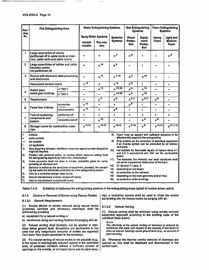
KTAA2101.3 Page 10
Fire Extinguishing Area Water Extinguishing Systems Gas Extinguishing Foam ExtinguishingRun- gSystems SystemsningNo. Spray Water Systems Sprinkier Room Equip- Heavy Light and
normal fine noz- Systems Protec- ment Foam Mediumnozzles ztesidon Protec- Foam
tion
I Large assemblies of cables:partitioned off in cable ducts or chan- + + 01) o I - 0 3nels, cable wells and cable rooms
2 Large assemblies of cables and cable + 015) 0 4) - -
transition points:not partitioned off
3 Rooms with electronic data processing - 14) o ) 18) 0 2) o 14) -
and electronics
Associated conduit rooms o 13) + 0 13) o
2 ) / -
Switch gear, S 1000 V - o014 ) 0 5)11) o2 o21 -)
4 switch gear buildings 1000 V _ - _ o)5)18) 0 2 o0 -
5 Transformers + 1 ° o02) n oZ 2 °-
accessible o 13) + 2)
-
6 False-floor hollows_not accessible o 13) + o2 /e
Fuel-oil containing partitioned off + + + + + +7 components and not partitioned off + 15) = o V o 0
system noI attoe ff +o+-o o8
8 Storage rooms for combustible mate- o 10)12) o 10)12) 10 12) 02 )12) 0 01 o11)12)
rials
+ suitable 8) Foam must be applied with sufficient adhesion to beo partly suitable effective with regard to fire extinguishing.- not suitable 9) Only suitable as fire protection of Individual equipment/ not applicable if an inverse ignition can be precluded for all compo-
nent parts.1) Slow triggering behavior; additional measures against smoke dissipation 10) Not suitable for flammable liquids of hazard class A 1
might be required. and A 2 In accordance with VbF nor for combustible2) Problem with personal safety; no cooling effect; pressure buildup from gases.
fire extinguishing agent to be taken into consideration. 11) The expected fire Intensity and local conditions shall3) Foam generator shall not draw in smoke; possibility given for corre- not cause a premature destruction of the foam.
sponding air displacement. . 12) Cf. Section 7.1 para. 54) Sprinkler is suited as fire protection of equipment, provided, the remain- 13
ing fire loads are Individually protected by a fire extinguishing system. 13) Depending on the height.
5) Only as a controlled deluge valve facility. 14) As protection for the cabinets.
6) Only for transformers In small, closed-off rooms. 15) Depending on the room geometry and air flow.7) Only for transformers In closed-off rooms. 16) As protection of the buildings.
Table 7.1-1: Suitability of stationary fire extinguishing systems in fire-extinguishing areas typical of nuclear power plants
8.1.3 Dilution or Removal of Smoke along Rescue Routes
8.1.3.1 General Requirements
(1) Smoke dilution or smoke removal along rescue routes(protected corridors and necessary stairways) shall beachieved by providinga) equipment for a natural venting orb) mechanical airing and venting facilities for purging with air.
(2) Natural venting shall basically not be applied in stair-ways below ground level. Exceptions are permissible in thecase that only insignificant amounts of smoke are expectedfrom lower floor levels connected to the stairways..
(3) If a natural venting of rescue routes is not possible (e.g.,in the cases of radiologically relevant regions in the controlledarea, of protected corridors without a sufficient number ofopenings to the outside, or of closed doors due to plant secu-
rity), a ventilation system shall be used to dilute the smokepenetrating into the rescue routes by purging with air.
8.1.3.2 Natural Venting
(1) Natural venting shall be achieved using smoke removalequipment approved according to the building code of theindividual State (Land).
Note:The effectivity of the natural venting of stairways is reduced byrestrictions that apply with respect to the opening of exit doors orother air inlet-air openings above ground level (e.g., on account ofplant security).
(2) Whenever the thermal smoke removal of stairways areopened up, this shall be displayed and documented in thecontrol room.
KTA 2101.3 Page II
8.1.3.3 Mechanical Airing and Venting Facilities for Purg-ing with Air
(1) Regarding the mechanical airing and venting facilitiesoutside of the containment interior, the ventilation system forpurging with air shall be designed such that a sufficient dilu-tion of the smoke is achieved for the assumed duration of theescape procedure. The dilution factor shall be specified ineach individual case. The assumed duration of the escapeprocedure shall be specified in the fire protection concept.
Note:a) An escape procedure is generally assumed to take up to 15
minutes.b) The requirements with respect to the air volume flow rate of
the mechanical airing and venting facilities to be used for thedilution of smoke by purging can be reduced by consideringthe arrangement of annexes and air locks that lie between thefire room and the rescue route.
(2) The air flow shall be guided such that it purges the res-cue routes along their entire lengths and is supported as faras possible by thermal updraft.
(3) The supply of the amount of air required for diluting thesmoke shall be ensured by an additional ventilation system orby utilizing the air supply from other areas.
(4) It is recommended that the pressure difference in thevicinity of doorways does not exceed p = 50 Pa in order to avoidthat the force required for opening the doors becomes too large.
8.1.3.4 Stairways and Air Lock Annexes inside the Con-tainment of a PWR
(1) In the event of fire inside the containment of a PWR, asmuch as possible of the entire normal-operation inlet air flowshall normally be branched off for the airing of stairways andair lock annexes.
Note:The inlet air low is limited by the fact that openings penetratingthe containment must be kept small. The inlet air flow shall bespecified in each individual case.
(2) During major revisions when there is a significant in-crease in the number of persons inside the containment, theair supply to the stairways and air lock annexes shall be in-creased in the event of fire. The requirements shall be speci-fied in each individual case.
(3) The necessary controls with regard to paras. 1 and 2shall be performed remotely from the control room.
8.2 Controls, Displays, Power Supplies
8.2.1 Controls for Fire Dampers, Smoke Dampers andSmoke Exhaust Dampers
(1) If fire dampers must be closed before the soft-soldertriggering occurs for reasons of preventing the spreading ofsmoke (e.g., to keep the rescue routes in the controlled areafree of smoke or to protect sensitive components), these firedampers shall be provided with triggering that is independentof the soft-solder triggers.
(2) The independent triggering specified under para. 1 shallnormally be performed automatically by smoke detectors or atleast from well accessible local control stations. In the case ofdifficult accessibility, a remote triggering shall normally bepossible from the control room. It shall be checked in eachindividual case whether or not the automatic triggering bysmoke detectors can be applied.
(3) The smoke dampers in ventilation systems with air recir-culation shall be triggered by devices that react to smoke andare built into the air recirculation ducts.
Note:The suitability of the automatic triggering devices is tested in ac-cordance with the 'Construction and testing principles for shut-offdevices against smoke in ventilation ducts' issued by the GermanInstitute for Civil Engineering (DIB0.
(4) In the case that air conditioning and ventilation systemsare also employed for heat and smoke removal, it shall be en-sured that the required fire dampers and smoke exhaustdampers are properly controlled even under the room tem-peratures expected upon required operation (cf. Section 8.1.2).
(5) Additional triggering devices and motorized actuatorsmay be employed for different tasks, provided, they are com-pletely separated from the thermal triggers and the relatedclosing devices.
(6) In order to prevent an unwanted closing of the air inletflap caused by reversed currents, the controls for the smokeexhaust damper shall be designed such that this damperopens up automatically when a fire damper in the air exhaustduct closes.
Note:It is necessary that the smoke exhaust damper is automaticallyopened in order to prevent an unwanted closing of the air inletflap caused by a reversed flow of hot smoke.
8.2.2 Controls of Heat and Smoke Removal Systems
(1) The controls for the smoke removal for stairways shallbe installed near the exit to the outside and, additionally, atleast at the top floor. In case of an automatic triggering of thesmoke removal for stairways, one control station at the exitlevel is sufficient.
(2) In the case that air conditioning and ventilation systemsare also employed for the heat and smoke removal, theswitch-over from mixed or recirculated air operation to inletand exhaust air operation shall be triggered automatically bysmoke detectors.
(3) Early smoke detection and the design and arrangementof the switching and control equipment shall be such thatproper functioning of the heat and smoke removal systems isensured upon required operation. This applies, especially, tocomponents catching fire in the same room where theswitching and control equipment is installed.
(4) Thermal smoke removal shall, in addition to the trigger-ing devices in accordance with DIN 18 232-2 (soft-soldertrigger on the exhaust flap itself), be provided with on-sitedevices for their manual triggering.
8.2.3 Position Indicators, Alarms
(1) Fire dampers shall issue at least the following feedbacksignals:a) Each fire damper shall Individually signal its status 'NOT
OPEN' to the corresponding local control station. Each lo-cal control station shall send a corresponding group alarmto the control room.
b) Each fire damper shall Individually signal its status to thecontrol room area if this feedback is necessary for furthercontrol actions from the control room area such as'Smoke Removal ON' or if the fire damper is located in anarea where the creation of combustible gases is possible.
c) Each fire dampers in explosion endangered areas shallsignal its individual status 'NOT OPEN" to the controlroom area if ventilating actions are required with regard toexplosion protection.
(2) In addition to the fire damper position signals, the fol-lowing information shall be displayed at least at the respectivelocal control station:
KTA 2101.3 Page 12
a) the operation of those ventilation systems with functions in (e.g., the cables and routing including the controls) is main-the event of fire, I tained for the duration of the required function.
b) the closing of the fire protection doors (fire protectionclosure) which during normal operation are in the openposition for reasons of ventilation.
A corresponding group alarm shall be displayed in the controlroom.
(3) Each smoke exhaust damper shall signal its status'OPEN' to the corresponding local control station.
8.3 Design of Special Systems or Components
8.3.1 Stationary Activated Charcoal Filters and High-efficiency Particulate Air Filters
Note:Requirements regarding mobile filter systems are specified ineach individual case.
8.2.4 Routing of Cables for Controls and Signaling and for (1) Filter shells shall consist of non-combustible materialsOther Controls-Oriented Transmission Devices (cf. Sec. 4.2.1 para. 2 KTA 2101.1)
(1) Cables required for controls and feedback signaling shallbasically meet the requirements specified under Section 4.5.
(2) It is permissible, in deviation of para. 1, to route thecontrols and feedback signaling cables of fire dampers di-rectly through the room to be protected, provided, it is en-sured that the fire dampers are immediately triggered whenthe fire alarm is issued.
(3) Cables required for controls and feedback signaling of heatand smoke removal equipment shall be routed such that theequipment maintains its required functionality in the event of fire.
(4) In the case of fire dampers in accordance with KTA2101.1 Sec. 4.3.2 para. 2, the open-circuit principle shall beapplied to the design of the controls in order to prevent erro-neous triggering.
8.2.5 Controls for Ventilators
(1) Ventilators used exclusively for keeping the rescueroutes free from smoke shall be equipped with on-site controlsfor their manual triggering. In the case of stairways, theseventilators shall be triggered either remotely from the controlroom or automatically by smoke detectors.
The local control stations shall be located at the access pointsto the secured corridors and, in the case of stairways, at leastat the top and bottom levels as well as at the exit level. Incase of an automatic triggering of the ventilators, one controlstation at the exit level is sufficient.
(2) Ventilators used for the heat and smoke removal shallbe equipped with on-site controls for their manual triggering.These ventilators shall be, additionally, triggered either re-motely from the control room or automatically by smoke de-tectors. It shall be ensured that during the startup of thesmoke removal ventilator the corresponding smoke exhaustdamper is already open or that it can still be opened duringoperation of the ventilator.
(3) A buildup of impermissible pressures that could lead tofailure of the structural elements, e.g., due to insufficient inletair, shall be prevented.
8.2.6 Power Supply
(1) A reliable power supply shall be provided for the ventila-tion systems as specified under Section 8. The auxiliarypower supply in accordance with Sec. 2 para. 1 KTA 3701may be considered as sufficiently reliable.
(2) The ventilation systems specified under Section 8.1.1para. 3 shall, additionally, be connected to the emergencypower supply.
(3) All controls and displays of the ventilation systemsspecified under Section 8.1 shall be connected to the emer-gency power supply.
(2) Tightly closing ventilation flaps shall be arranged beforeand after filter units with activated charcoal. The ventilationflaps shall be triggered from the control room. Smoke detec-tors shall be installed in the duct on the inlet air side of thefirst ventilation flap. A fire damper shall be installed before thefilter if smoke temperatures above 100 "C can occur due tolocal conditions (e.g., duct length, mixture temperature, fireload, ingression of fire).
(3) If the exhaust air system is used for the removal ofsmoke then the activated charcoal filters and high-efficiencyparticulate air filters shall be bypassed.
(4) In order to be able to detect a fire in the activated charcoalfilters, alarm devices, e.g., carbon monoxide measuring de-vices, shall be installed after the filters and before the ventilationflaps. The alarms shall be displayed in the control room.
Note:In non-flow-through filter system the natural buildup of the carbonmonoxide concentration can lead to false alarms.
(5) In the room where activated charcoal filters and high-efficiency particulate air filters are installed, combustible ma-terials are permissible only in such amounts as are requiredfor the operation of these filters and of the ventilation systems.
8.3.2 Accident Filtration Systems
Note:Accident filtration Systems are the exhaust air filtration facilities inaccordance with KTA 3601.
(1) Accident filtration systems shall not be used for the re-moval of smoke. The requirements specified under Sec-tion 8.3.1 paras. 2 through 4 do not apply to accident filtrationfacilities.
(2) The penetrations of air ducts of the accident filtrationsystem through structural partitioning elements that have fireprotection functions shall be designed in accordance with KTA2101.1 Sec. 4.3.1 para. 7. The design shall also be such thata transmittal of smoke is prevented.
Note:This may be achieved for the penetration Itself by designing it asa steel pipe penetration In accordance with DIN 4102-11.
9 Location of Alarms, Displays and Control ElementsRelevant to Fire Protection
Note:Alarms of the fire detection and alarm system are dealt with inSection 5, the alarms, displays and control elements of the fireextinguishing systems in Section 7.5.
(1) The remote controls and the displays of the feedbacksignals from the fire dampers and from the close-and-retainsystems for doors specified under Section 5.6 shall be locatedin a control room annex or in local control stations. Positionindicators shall be provided in the control room for those fire
(4) It shall be ensured in the case of ventilation systems withspecified functions in the event of fire, that the power supply
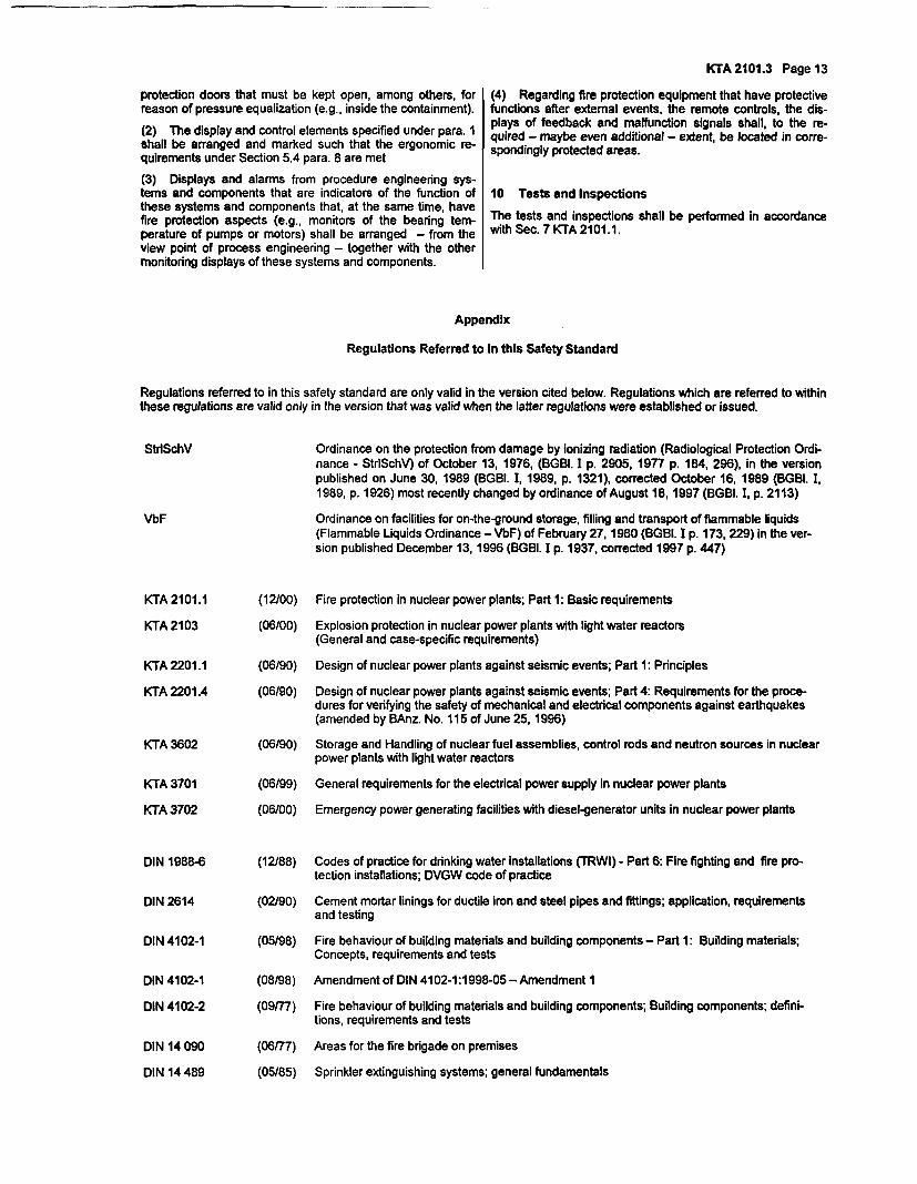
KTA 2101.3 Page 13
protection doors that must be kept open, among others, forreason of pressure equalization (e.g., inside the containment).
(2) The display and control elements specified under para. Ishall be arranged and marked such that the ergonomic re-quirements under Section 5.4 para. 8 are met
(3) Displays and alarms from procedure engineering sys-tems and components that are indicators of the function ofthese systems and components that, at the same time, havefire protection aspects (e.g., monitors of the bearing tem-perature of pumps or motors) shall be arranged - from theview point of process engineering - together with the othermonitoring displays of these systems and components.
(4) Regarding fire protection equipment that have protectivefunctions after external events, the remote controls, the dis-plays of feedback and malfunction signals shall, to the re-quired - maybe even additional - extent, be located in corre-spondingly protected areas.
10 Tests and Inspections
The tests and inspections shall be performed in accordancewith Sec. 7 KTA 2101.1.
Bndlx
Regulations Referred to In this Safety Standard
Regulations referred to in this safety standard are only valid in the version cited below. Regulations which are referred to withinthese regulations are valid only in the version that was valid when the latter regulations were established or issued.
StrlSchV Ordinance on the protection from damage by ionizing radiation (Radiological Protection Ordi-nance - StrlSchV) of October 13, 1976, (BGBI. I p. 2905, 1977 p. 184, 296), in the versionpublished on June 30, 1989 (BGBI. I, 1989, p. 1321), corrected October 16, 1989 (BGBI. I,1989, p. 1926) most recently changed by ordinance of August 18, 1997 (BGBI. I, p. 2113)
VbF Ordinance on facilities for on-the-ground storage, filling and transport of flammable liquids(Flammable Liquids Ordinance - VbF) of February 27, 1980 (BGBI. I p. 173, 229) in the ver-sion published December 13, 1996 (BGBI. I p. 1937, corrected 1997 p. 447)
KTA 2101.1 (12100) Fire protection in nuclear power plants; Part 1: Basic requirements
KTA 2103 (06/00) Explosion protection in nuclear power plants with light water reactors(General and case-specific requirements)
KTA 2201.1 (06/90) Design of nuclear power plants against seismic events; Part 1: Principles
KTA 2201.4 (06/90) Design of nuclear power plants against seismic events; Part 4: Requirements for the proce-dures for verifying the safety of mechanical and electrical components against earthquakes(amended by BAnz. No. 115 of June 25, 1996)
KTA 3602 (06190) Storage and Handling of nuclear fuel assemblies, control rods and neutron sources in nuclearpower plants with light water reactors
KTA 3701 (06/99) General requirements for the electrical power supply in nuclear power plants
KTA 3702 (06/00) Emergency power generating facilities with diesel-generator units in nuclear power plants
DIN 1988-6 (12/88) Codes of practice for drinking water installations (TRWI) - Part 6: Fire fighting and fire pro-tection installations; DVGW code of practice
DIN 2614 (02/90) Cement mortar linings for ductile iron and steel pipes and fittings; application, requirementsand testing
DIN 4102-1 (05/98) Fire behaviour of building materials and building components - Part 1: Building materials;Concepts, requirements and tests
DIN 4102-1 (08/98) Amendment of DIN 4102-1:1998-05 - Amendment 1
DIN 4102-2 (09/77) Fire behaviour of building materials and building components; Building components; defini-tions, requirements and tests
DIN 14 090
DIN 14 489
(06177)
(05/85)
Areas for the fire brigade on premises
Sprinkler extinguishing systems; general fundamentals
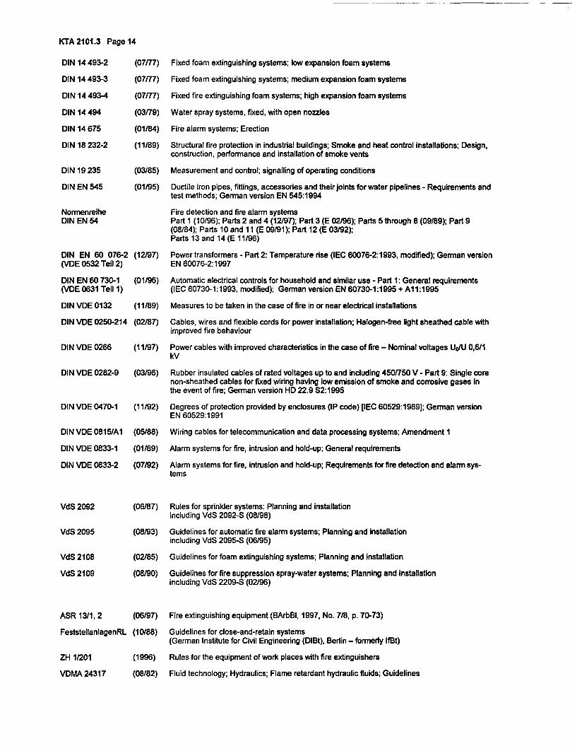
KTA 2101.3 Page 14
DIN 14 493-2 (07177) Fixed foam extinguishing systems; low expansion foam systems
DIN 14 493-3 (07/77) Fixed foam extinguishing systems; medium expansion foam systems
DIN 14 493-4 (07/77) Fixed fire extinguishing foam systems; high expansion foam systems
DIN 14 494 (03179) Water spray systems, fixed, with open nozzles
DIN 14 675 (01/84) Fire alarm systems; Erection
DIN 18 232-2 (11/89) Structural fire protection in industrial buildings; Smoke and heat control installations; Design,construction, performance and installation of smoke vents
DIN 19 235 (03/85) Measurement and control; signalling of operating conditions
DIN EN 545 (01/95) Ductile iron pipes, fittings, accessories and their joints for water pipelines - Requirements andtest methods; German version EN 545:1994
Normenreihe Fire detection and fire alarm systemsDIN EN 54 Part 1 (10/96); Parts 2 and 4 (12/97); Part 3 (E 02/96); Parts 5 through 8 (09/89); Part 9
(08/84); Parts 10 and 11 (E 09/91); Part 12 (E 03/92);Parts 13 and 14 (E 11/96)
DIN EN 60 076-2 (12/97) Power transformers - Part 2: Temperature rise (IEC 60076-2:1993, modified); German version(VDE 0532 Teil 2) EN 60076-2:1997
DIN EN 60 730-1 (01/96) Automatic electrical controls for household and similar use - Part 1: General requirements(VDE 0631 Teil 1) (IEC 60730-1:1993, modified); German version EN 60730-1:1995 + Al 1:1995
DIN VDE 0132 (11/89) Measures to be taken in the case of fire in or near electrical installations
DIN VDE 0250-214 (02/87) Cables, wires and flexible cords for power installation; Halogen-free light sheathed cable withimproved fire behaviour
DIN VDE 0266 (11/97) Power cables with improved characteristics in the case of fire - Nominal voltages UoIU 0,6/1kV
DIN VDE 0282-9
DIN VDE 0470-1
DIN VDE 0815/Al
DIN VDE 0833-1
DIN VDE 0833-2
VdS 2092
VdS 2095
VdS 2108
VdS 2109
ASR 1311, 2
FeststellanlagenRL
ZH 1/201
VDMA 24317
(03/96) Rubber insulated cables of rated voltages up to and including 450/750 V - Part 9: Single corenon-sheathed cables for fixed wiring having low emission of smoke and corrosive gases inthe event of fire; German version HD 22.9 S2:1995
(11/92) Degrees of protection provided by enclosures (IP code) fIEC 60529:1989]; German versionEN 60529:1991
(05/88) Wiring cables for telecommunication and data processing systems; Amendment 1
(01/89) Alarm systems for fire, intrusion and hold-up; General requirements
(07/92) Alarm systems for fire, intrusion and hold-up; Requirements for fire detection and alarm sys-tems
(06/87) Rules for sprinkler systems: Planning and installationincluding VdS 2092-S (08/98)
(08/93) Guidelines for automatic fire alarm systems; Planning and installationincluding VdS 2095-S (06/95)
(02/85) Guidelines for foam extinguishing systems; Planning and installation
(08190) Guidelines for fire suppression spray-water systems; Planning and installationincluding VdS 2209-S (02/96)
(06197)
(10188)
(1996)
(08/82)
Fire extinguishing equipment (BArbBI, 1997, No. 7/8, p. 70-73)
Guidelines for close-and-retain systems(German Institute for Civil Engineering (DlBt), Berlin - formerly IflBt)
Rules for the equipment of work places with fire extinguishers
Fluid technology; Hydraulics; Flame retardant hydraulic fluids; Guidelines