Embed Size (px)
Citation preview
SAFETY LOCKING DEVICES
L200
Heavy-Duty L200 Safety Locking Device on a very large gate in a logistics opera-tion with forklift traffic
The L200 Safety Locking Device designedfor highly demanding applications is pre-destined for guarding large protectivedoors and sliding gates, in logistics opera-tions, for example, or with very big machin-ery, and under harsh conditions. It is insen-sitive here to high recoil forces, such aswhen massive, heavy doors and gatesslam. The guard interlocking is especiallyimpressive due to its slender but veryrobust structure. It is used according torequirements with appropriate lockingtypes (spring-force or magnet-actuatedlocking). The contact set enables safety-related integration up to category 4 inaccordance with EN ISO 13849. If anescape route is planned, then when usingthe PB variant, the locking device can bequickly unlocked by pressing the ergonom-ically optimized unlocking button installedin the danger zone. The available exten-sions for the emergency release buttonmake it easy to adapt to local conditions onsite.
Typical areas of application Use with harsh ambient conditions and
high mechanical demand
Access guarding on big machinery and systems with dangerous movementsthat run-on
Guard interlocking of heavy protectivedoors or sliding gates where theprevention of undefined interruptions is required
Phone: 800.894.0412 - Fax: 888.723.4773 - Web: www.clrwtr.com - Email: [email protected]
Saf
ety
Sw
itch
es
Saf
ety
Lo
ckin
g
Dev
ices
S
afet
y C
om
man
d
Dev
ices
S
afet
y R
elay
s P
rog
ram
mab
le
Saf
ety
Co
ntr
olle
rs
Acc
esso
ries
Glo
ssar
yP
rod
uct
Fin
der
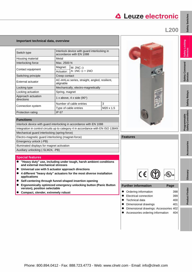
L200
Important technical data, overview
Switch type Interlock device with guard interlocking in accordance with EN 1088
Housing material Metal
Interlocking force Max. 2500 N
Contact equipmentMagnet: M: 2NC
A: 1NC + 1NOActuator:
Switching principle Creep contact
External actuator AC-AHLxx series, straight, angled, resilient, alignable
Locking type Mechanically, electro-magnetically
Locking actuation Spring, magnet
Approach actuation directions 1 x above, 4 x side (90°)
Connection systemNumber of cable entries 3
Type of cable entries M20 x 1.5
Protection rating IP 67
FunctionsInterlock device with guard interlocking in accordance with EN 1088
Integration in control circuits up to category 4 in accordance with EN ISO 13849
Mechanical guard interlocking (spring-force)
Electro-magnetic guard interlocking (magnet-force)
Emergency unlock (-PB)
Illuminated displays for magnet activation
Auxiliary unlocking (-SLM24, -PB)
Special features "Heavy duty" use, including under tough, harsh ambient conditions
and external mechanical stresses Universal use with 5 actuator approach directions 4 different "heavy duty" actuators for the most diverse installation
applications Self-centering through funnel-shaped insertion opening Ergonomically optimized emergency unlocking button (Panic Button
version), position selectable Compact, slender, extremely robust
Features
Further information Page
Ordering information 398 Electrical connection 399
Technical data 400
Dimensional drawings 401 Dimensional drawings: Accessories 402
Accessories ordering information 404
Phone: 800.894.0412 - Fax: 888.723.4773 - Web: www.clrwtr.com - Email: [email protected]
SAFETY LOCKING DEVICES
Actuators must be ordered separately, see page 404.
Ordering information
L200Included in delivery: Application information (print document)
Functions: Interlock device with guard interlocking inaccordance with EN 1088, emergency unlocking button (-PB), illuminated displays, auxiliary release (-SLM24, -PB)
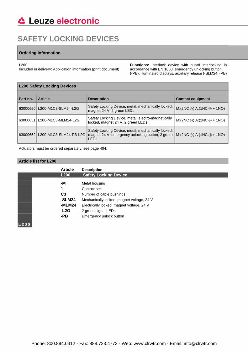
L200 Safety Locking Devices
Part no. Article Description Contact equipment
63000650 L200-M1C3-SLM24-L2G Safety Locking Device, metal, mechanically locked, magnet 24 V, 2 green LEDs M:(2NC ) A:(1NC + 1NO)
63000651 L200-M1C3-MLM24-L2G Safety Locking Device, metal, electro-magnetically locked, magnet 24 V, 2 green LEDs M:(2NC ) A:(1NC + 1NO)
63000652 L200-M1C3-SLM24-PB-L2GSafety Locking Device, metal, mechanically locked, magnet 24 V, emergency unlocking button, 2 green LEDs
M:(2NC ) A:(1NC + 1NO)
Article list for L200
Article DescriptionL200 Safety Locking Device
-M Metal housing
1 Contact set
C3 Number of cable bushings
-SLM24 Mechanically locked, magnet voltage, 24 V
-MLM24 Electrically locked, magnet voltage, 24 V
-L2G 2 green signal LEDs
-PB Emergency unlock button
L 2 0 0
Phone: 800.894.0412 - Fax: 888.723.4773 - Web: www.clrwtr.com - Email: [email protected]
L200 Saf
ety
Sw
itch
es
Saf
ety
Lo
ckin
g
Dev
ices
S
afet
y C
om
man
d
Dev
ices
S
afet
y R
elay
s P
rog
ram
mab
le
Saf
ety
Co
ntr
olle
rs
Acc
esso
ries
Glo
ssar
yP
rod
uct
Fin
der
Electrical connection
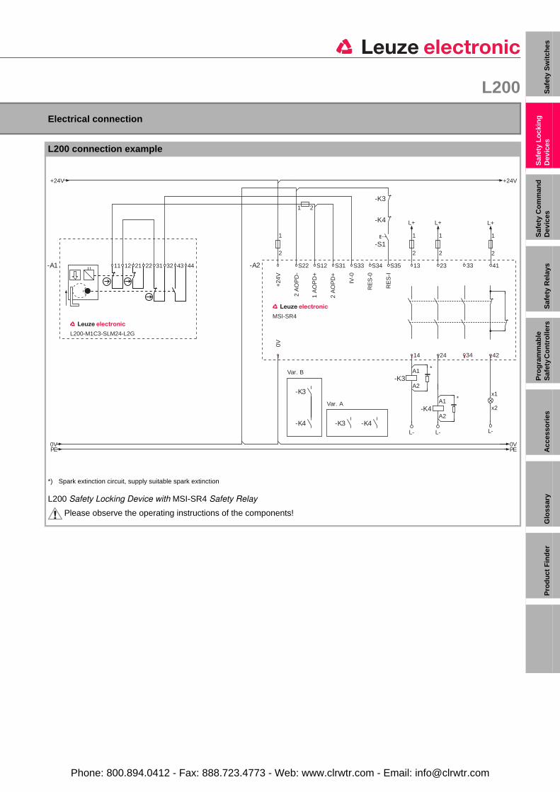
L200 connection example
*) Spark extinction circuit, supply suitable spark extinction
L200 Safety Locking Device with MSI-SR4 Safety Relay
Please observe the operating instructions of the components!
L200-M1C3-SLM24-L2G
11 12 21 22-A1 3231
0VPE PE
0V
Var. B
Var. A
MSI-SR4
-K3
-A2
-K4-K4
-K3 x1
x2
L-
13 23 41S22 S12 S31 S33 S34 S35 33
+24
V
2 A
OP
D-
1 A
OP
D+
2 A
OP
D+
IV-0
RE
S-0
RE
S-I
1
2
L+
-K3
-K4
14 24 42
0V
34
1
2
1
2
L+ L+
A1
A2-K3
L- L-
*
A1
A2-K4
*
1
2
+24V +24V
4443
1 2
-S1
Phone: 800.894.0412 - Fax: 888.723.4773 - Web: www.clrwtr.com - Email: [email protected]
SAFETY LOCKING DEVICES
Please note the additional information in the connecting and operating instructions at Leuze website.
Technical data
Switch type Interlock device with guard interlocking in accordance with EN 1088Service life (TM ) in accordance with EN ISO 13849-1 20 years
Number of cycles until 10% of the components have a failure to danger (B10d) 5,000,000
Locking type Mechanically (L200-M1C3-SLM24-L2G, L200-M1C3-SLM24-PB-L2G)Electro-magnetically (L200-M1C3-MLM24-L2G)
Locking actuation Spring (L200-M1C3-SLM24-L2G, L200-M1C3-SLM24-PB-L2G)Magnet (L200-M1C3-MLM24-L2G)
Ambient temperature, operation -25…+60°CDirt levels, external, in accordance with EN 60947-1 3
Housing material MetalExternal actuator AC-AHLxx series, straight, angled, resilient, alignableDimensions See dimensional drawingProtection rating IP 67Contact protection EarthingApproach actuation directions 1 x above, 4 x side (90°)Mechanical life time in accordance with IEC 6047-5-1 1 x 10⁶ actuation cycles
Actuation frequency according to IEC 6047-5-1 Max. 600 per hour
Approach speed Max. 0.5 m/sActuation force (pull-out) 30 NRecoil tolerance 4.5 mmInterlocking force Max. 2500 N
Contact equipmentMagnet: 2NC Actuator: 1NC + 1NO
Switching principle Creep contactContact opening Force-fitContact material Silver alloyMagnet operating voltage and tolerance 24 V DC (-10% to +25%)Duty cycle 100%Power consumption Average, 9 VAUsage category in accordance with EN 60947-5-1
AC 15: Ue 250 V, Ie 5 ADC 13: Ue / Ie: 24 V / 6 A, 125 V / 1.1 A, 250 V / 0.4 A
Rated insulation voltage 250 V AC, 300 V DCConventional thermal current Max. 10 A
Short-circuit protection according to IEC 60269-1
Magnet 0.5 A, 24 V, type gGSafety circuit 500 V, 10 A, type gG
Connection systemNumber of cable entries 3Type of cable entries M20 x 1.5Cable cross-section (wire) 1 x 0.34 mm² to 2 x 1.5 mm²
Phone: 800.894.0412 - Fax: 888.723.4773 - Web: www.clrwtr.com - Email: [email protected]
L200 Saf
ety
Sw
itch
es
Saf
ety
Lo
ckin
g
Dev
ices
S
afet
y C
om
man
d
Dev
ices
S
afet
y R
elay
s P
rog
ram
mab
le
Saf
ety
Co
ntr
olle
rs
Acc
esso
ries
Glo
ssar
yP
rod
uct
Fin
der
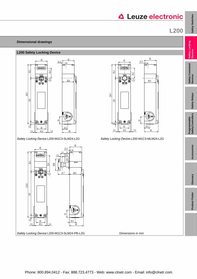
Dimensional drawings
L200 Safety Locking Device
Safety Locking Device L200-M1C3-SLM24-L2G Safety Locking Device L200-M1C3-MLM24-L2G
Dimensions in mmSafety Locking Device L200-M1C3-SLM24-PB-L2G
33.2
144
45.2
5.4
302.440.22.4
5.519
4.7
4012.3
18.346
40
38.8
24
33.2
40
5.4
302.4 40.2 2.4
5.514
445
.219
4.7
12.3
18.346
24
38.8
40
53.465
.414
45.5 30
40
5.4
40.22.4 2.4
214.9
18.3
24
12.3
5.5 9.515 15
46
40
Ø 17
Ø38
38.837.7
Phone: 800.894.0412 - Fax: 888.723.4773 - Web: www.clrwtr.com - Email: [email protected]
SAFETY LOCKING DEVICES
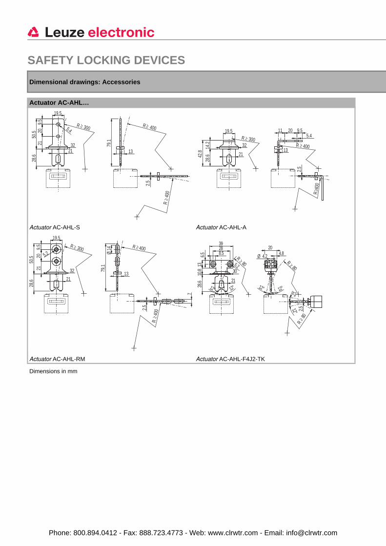
Dimensions in mm
Dimensional drawings: Accessories
Actuator AC-AHL…
Actuator AC-AHL-S Actuator AC-AHL-A
Actuator AC-AHL-RM Actuator AC-AHL-F4J2-TK
R 300
19.5
9.5
2021
50.5
28.6
5.4
3221
≥
R
400
R 400
13
79.1
2.5
≥
≥
R 30032
21
19.5
14.2
28.642
.8
≥R 400
R 4
00
2.5
13
9.520115.4
≥
≥
R 300
19,5
9,5
2021
50,5
28,6
32
21
5,2≥ R 400
R
400
Ø14
13
79,1
2,5
7
≥
≥
12°1
1310
.828
.66.5
2°21
2839
8.5
80≥
5.20
R
3
12°
4.8Ø 4.2
20
1
12°
R80
2°
.5≥
R80
≥
2
12°
Phone: 800.894.0412 - Fax: 888.723.4773 - Web: www.clrwtr.com - Email: [email protected]
L200 Saf
ety
Sw
itch
es
Saf
ety
Lo
ckin
g
Dev
ices
S
afet
y C
om
man
d
Dev
ices
S
afet
y R
elay
s P
rog
ram
mab
le
Saf
ety
Co
ntr
olle
rs
Acc
esso
ries
Glo
ssar
yP
rod
uct
Fin
der
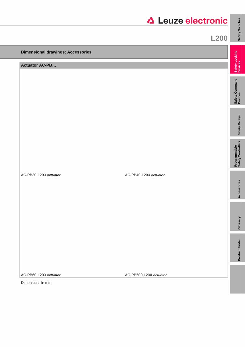
Dimensions in mm
Dimensional drawings: Accessories
Actuator AC-PB…
AC-PB30-L200 actuator AC-PB40-L200 actuator
AC-PB60-L200 actuator AC-PB500-L200 actuator
18.3
24
5.5 9.2
46
Ø38
Ø17
30 max
14.7
44.7
5.5 12.2
Ø38
Ø17
40 MAX
17.7
Ø17
5.5 12.2
Ø38
60 MAX
17.7
5.5Ø
17
500 MAX60 MIN
25 MAX10 MIN
Ø38
Phone: 800.894.0412 - Fax: 888.723.4773 - Web: www.clrwtr.com - Email: [email protected]
SAFETY LOCKING DEVICES
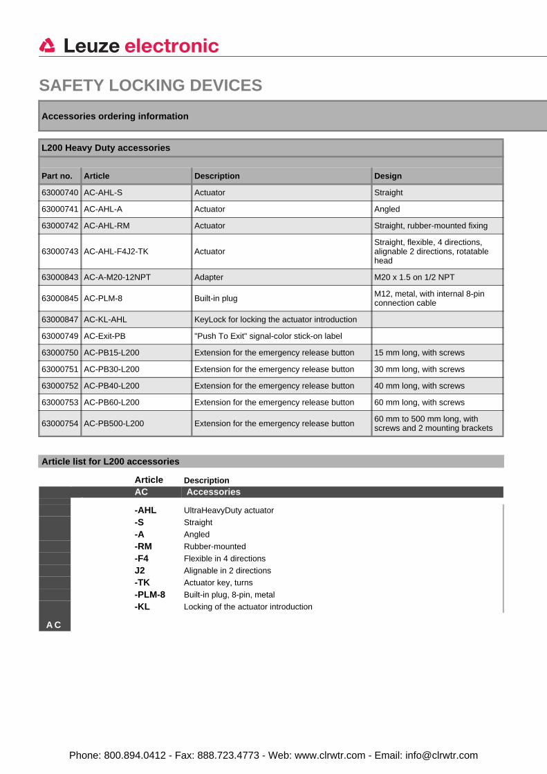
Accessories ordering information
L200 Heavy Duty accessories
Part no. Article Description Design
63000740 AC-AHL-S Actuator Straight
63000741 AC-AHL-A Actuator Angled
63000742 AC-AHL-RM Actuator Straight, rubber-mounted fixing
63000743 AC-AHL-F4J2-TK ActuatorStraight, flexible, 4 directions, alignable 2 directions, rotatable head
63000843 AC-A-M20-12NPT Adapter M20 x 1.5 on 1/2 NPT
63000845 AC-PLM-8 Built-in plug M12, metal, with internal 8-pin connection cable
63000847 AC-KL-AHL KeyLock for locking the actuator introduction
63000749 AC-Exit-PB "Push To Exit" signal-color stick-on label
63000750 AC-PB15-L200 Extension for the emergency release button 15 mm long, with screws
63000751 AC-PB30-L200 Extension for the emergency release button 30 mm long, with screws
63000752 AC-PB40-L200 Extension for the emergency release button 40 mm long, with screws
63000753 AC-PB60-L200 Extension for the emergency release button 60 mm long, with screws
63000754 AC-PB500-L200 Extension for the emergency release button 60 mm to 500 mm long, with screws and 2 mounting brackets
Article list for L200 accessories
Article DescriptionAC Accessories
-AHL UltraHeavyDuty actuator
-S Straight
-A Angled
-RM Rubber-mounted
-F4 Flexible in 4 directions
J2 Alignable in 2 directions
-TK Actuator key, turns
-PLM-8 Built-in plug, 8-pin, metal
-KL Locking of the actuator introduction
A C
Phone: 800.894.0412 - Fax: 888.723.4773 - Web: www.clrwtr.com - Email: [email protected]


![Mitsubishi L200 [134hp_175hp (4D56)]](https://img.pdfslide.us/doc/110x75/55cf9b51550346d033a5960b/mitsubishi-l200-134hp175hp-4d56.jpg)