Embed Size (px)
Citation preview

Letter of Transmittal
November 17, 2014
Ali Said
Structural Thesis Advisor
The Pennsylvania State University
Dear Doctor Said,
The following technical report fulfills the fourth Technical Report assigned by the structural
faculty for senior thesis.
Technical Report 4 includes a structural analysis of the lateral system in 11141 Georgia Ave in
Wheaton, MD. Included is a list of codes and documents used to compile this report. A review
of the lateral load calculations and values is included as well as typical member spot checks for
lateral loads and lateral load modeling.
Thank you for your time in reviewing this report. I look forward to hearing your feedback and
discussing it with you.
Sincerely,
Samantha deVries
Enclosed: Technical Report 4

TECHNICAL REPORT 1 SAMANTHA DEVRIES STRUCTURAL OPTION
11141 GEORGIA AVENUE 2
11141 Georgia Avenue
Located in Wheaton, MD
Technical Report 4
Samantha deVries
Structural Option
Advisor: Ali Said
November 17, 2014

TECHNICAL REPORT 1 SAMANTHA DEVRIES STRUCTURAL OPTION
11141 GEORGIA AVENUE 3
Table of Contents
Executive Summary………………………………………………………………………………………4
Purpose……………………………………………………………………………………………………5
Building Abstract………………………………………...……………………………………….……….6
Site Plan and Location of Building……………………………………………………………...………7
Documents used during preparation of report…….…………………………….…………………….8
Load Summary…..…………………………………………………………………………….………….9
Gravity Loads…………………………………..……………………………………..……..…….…9
Wind Load Summary…………………………………………….……….………………..…….…10
Seismic Load Summary ………………………………………..…..…………...………..…….…12
Lateral Load Modeling………………………………………………………..………………..…….…14
Hand Calculations………………………………………………………...………………..…….…14
Calculation Process………………………………………………..…………...……..…….…15
Relative Stiffness……………………………………………………..………………..…….…16
Story Shears……………………………………………..………………………...…..…….…17
Summary of Distributed Loads……………………………………..…….…………..…….…18
Three-dimensional modeling……………………………………..………………..……..…….…19
Story Drift Check…….……………………………………………..…………...……..…….…21
Member Forces……………………………..………………………..………………..…….…22
Joint Reactions……….……………………………………….…………………...…..…….…24
Hand Methods and Computer Analysis Comparison……………………….………....…….…25
Typical Member Spot Checks for Lateral Loads…………………..………………………..…….…27
Appendix……………………………………………………..…………………………………………..31
Lateral Framing Plans………..……………………………………………...……………………..31
Hand Method Excel Calculations………..……………………………....………………………..34

TECHNICAL REPORT 1 SAMANTHA DEVRIES STRUCTURAL OPTION
11141 GEORGIA AVENUE 4
Executive Summary
11141 Georgia Avenue, located in Wheaton, MD, is a 1960’s concrete office building on which a
7-story steel addition was completed in August 2014 for $20 million. The building is a high rise
apartment building with one and two bedroom studios, a rooftop terrace and penthouse, and is
conveniently located next to the metro station.
The Foundations are spread footings with piers and a foundation retaining wall where the building
steps from the lowest basement level to the next. Modifications were required to the foundations
and slab on grade only where a new elevator pit was added and the old pit was removed.
The structure of the original building is reinforced concrete with typical two-way concrete slab
bays that are approximately 22’ by 21’. Again, the slabs in the original building only required
modifications where new stairwells and elevators were added and the original ones were
removed. The addition’s structure is framed in structural steel with rolled W-shapes for the
columns, girders, and beams, and composites joists for the bays in the floors and on the
roof. Each floor has metal deck with a concrete topping.
The lateral system consists of concrete moment frames in the original structure, and steel moment
frames in the new structure. Some columns were expanded for additional stiffness to resist an
increase in lateral loads due to an increased building height.
There are many joints and connections that involved tying the new columns, beams, and other
structural elements into the original building through drilling a hole to embed and grout rebar,
anchors, or other connections.
The loads used in the structural design on the project all followed IBC 2009, which allows the use
of ASCE 7-05. Due to a change in building use which allows a smaller reduced live load, the
removal of the original penthouse, and the use of steel rather than concrete for the addition, the
total loads reaching the foundations were close to the original 1960’s design loads.

TECHNICAL REPORT 1 SAMANTHA DEVRIES STRUCTURAL OPTION
11141 GEORGIA AVENUE 5
Purpose
The Purpose of this report is to analyze the lateral system in 11141 Georgia Avenue in
Wheaton, MD. Both hand methods and a three-dimensional computer model analysis will be
used to compare to each other. These results will be used for the purpose of understanding
how lateral loads are distributed in the building as well as spot checking a lateral frame for
strength and drift. The lateral system analysis will be further used to guide the upcoming
proposal for redesign work during the upcoming spring semester.

TECHNICAL REPORT 1 SAMANTHA DEVRIES STRUCTURAL OPTION
11141 GEORGIA AVENUE 6

TECHNICAL REPORT 1 SAMANTHA DEVRIES STRUCTURAL OPTION
11141 GEORGIA AVENUE 7
Site Plan and Location of Building
11141 Georgia Ave is Located in Wheaton Maryland near the Wheaton Metro Station. To the
west of the site is a mainly commercial zone, while to the east is a residential zone. The site itself
is combined commercial-residential. Figures 1 and 2 below illustrate the building’s location.
Figure 1: Building Location on Site, Courtesy of Bonstra Haresign Architects
State College, PA
Harrisburg, PA
11141 Georgia Ave
Figure 2: Map showing building location relative to State College and Harrisburg

TECHNICAL REPORT 1 SAMANTHA DEVRIES STRUCTURAL OPTION
11141 GEORGIA AVENUE 8
Documents used during preparation of report
The following is a list of the structural codes used on the project. The codes used in the original
1962 drawings were not available. The codes used on the new addition to and renovation of the
original building will be the referenced codes in this technical report.
International Code Council
International Building Code 2009
American Society of Civil Engineers
ASCE 7-05: Minimum Design Loads for Buildings and Other Structures
American Concrete Institute
ACI 318-11
American Institute of Steel Construction
AISC Steel Manual 14th Edition
Vulcraft Deck Catalog
Steel Joist Institute
Standard Specifications for Composite Steel Joists
Previous Course Notes
Concrete Design (AE 402)
Advanced Concrete Design (AE 431)
Advanced Steel Design (AE 403)
Computer Modeling of Building Structures (AE 530)

TECHNICAL REPORT 1 SAMANTHA DEVRIES STRUCTURAL OPTION
11141 GEORGIA AVENUE 9
Gravity Loads Summary
Below is a summary of the gravity loads calculated in Technical Report 2:
Roof Dead Load (Penthouse) = 27 psf
Roof Dead Load (12th Level Terrace) = 98 psf
Roof Live Load (Penthouse) = 30 psf
Roof Live Load (12th Level Terrace) = 100 psf
Snow Load = 20 psf with max drift of 65 psf
Floor Dead Load (steel) = 75 psf
Floor Dead Load (concrete) = 105 psf for 6.5” slab
= 123 psf for 8” slab
Floor Live Load = 40 psf (Residential, Parking, Corridors above 1st level)
= 100 psf (Lobbies, Stairs, Exits)
Exterior Wall (original) = 992 plf
Exterior Wall (metal panels) = 443 plf
Exterior Wall (new brick) = 487 plf
At drop panels = 9 psf (additional to slab)

TECHNICAL REPORT 1 SAMANTHA DEVRIES STRUCTURAL OPTION
11141 GEORGIA AVENUE 10
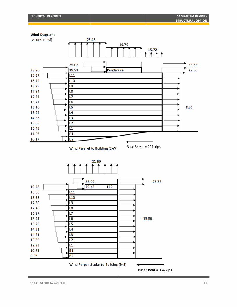
Wind Loads Summary
The following section includes a summary of the wind loads calculated in Technical Report 2.
Below is the general wind design information.
B = 60 ft
L = 214 ft
Basic Wind Speed = 90 mph
Mean Height = 145 ft
Occupancy Category II
Exposure Category B
Topographic Factor = 1
Gust Effect Factor = 0.85
Wind Load at each level = qzGfCp – qi (+/- GCpi)
Base Shear = ∑ (Plevel i * Hstory * B or L)
Overturning Moment = ∑ (Plevel i * Hstory * B or L* distance from base at level)
The Following Page includes a summary of the wind loads determined at each level and the Base
Shear. Technical Report 2 determined that wind loads control over seismic loads for lateral.
TECHNICAL REPORT 1 SAMANTHA DEVRIES STRUCTURAL OPTION
11141 GEORGIA AVENUE 11
Base Shear = 227 kips
Base Shear = 964 kips

TECHNICAL REPORT 1 SAMANTHA DEVRIES STRUCTURAL OPTION
11141 GEORGIA AVENUE 12
Seismic Loads Summary
The following section includes a summary of the seismic loads calculated in Technical Report 2.
Below is the general seismic design information.
Site Class C
SS = 0.155g
S1 = 0.050g
SDS = 0.124g
SD1 = 0.057g
Seismic Design Category A
Total Seismic Weight = 20,864 kip
Response Modification Factor = 3.0
Ta = 1.4s
TL = 5.5S
CS = 0.116
Seismic Load at each level = V * (wxhxk / ∑wihi
k)
Base Shear = ∑ (Plevel i)
Overturning Moment = ∑ (Plevel i * distance from base at level)
The Following Page includes a summary of the seismic loads determined at each level and the
Base Shear and overturning moment. Technical Report 2 determined that wind loads control over
seismic loads for lateral.

TECHNICAL REPORT 1 SAMANTHA DEVRIES STRUCTURAL OPTION
11141 GEORGIA AVENUE 13

TECHNICAL REPORT 1 SAMANTHA DEVRIES STRUCTURAL OPTION
11141 GEORGIA AVENUE 14
Lateral Load Modeling
Lateral loads in 11141 Georgia Ave were analyzed using a combination of hand methods and
software analysis.
Hand Methods Overview and Assumptions
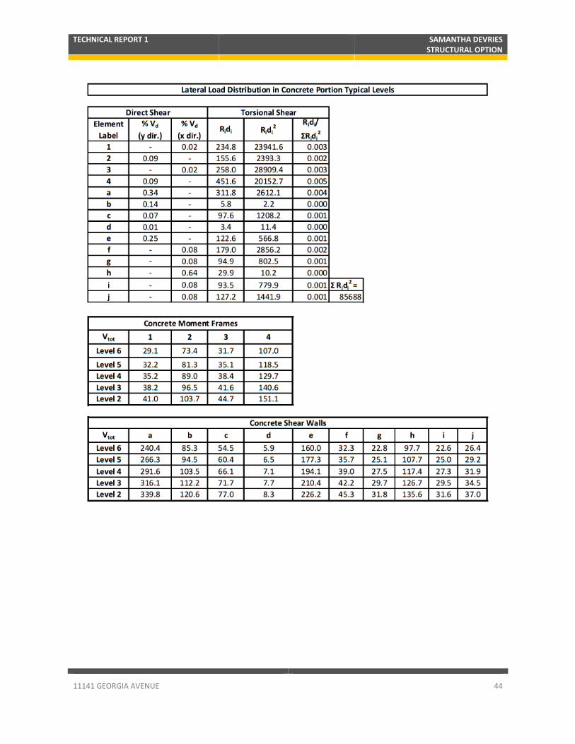
Hand calculations were completed by determining the stiffness of the frames relative to each
other and then distributing loads based on relative stiffness at each level. Since wind was the
controlling case over seismic, only wind was considered in the hand methods. Seismic will be
studied in addition to wind in the 3D computer model. The distributed load at each level is the
shear force at that level, which was found by converting the wind pressures into a point force at
each level and summing up the total force at a given level and all of the levels above it. The
next few pages include the calculation process, a chart of relative stiffness of the frames and
walls, the shear loads used for distribution, and the final loads in the frames and shear walls at
each level. Additional calculation charts and plans with the lateral elements highlighted and
labeled for reference in the calculations are available in the Appendix.

TECHNICAL REPORT 1 SAMANTHA DEVRIES STRUCTURAL OPTION
11141 GEORGIA AVENUE 15

TECHNICAL REPORT 1 SAMANTHA DEVRIES STRUCTURAL OPTION
11141 GEORGIA AVENUE 16

TECHNICAL REPORT 1 SAMANTHA DEVRIES STRUCTURAL OPTION
11141 GEORGIA AVENUE 17

TECHNICAL REPORT 1 SAMANTHA DEVRIES STRUCTURAL OPTION
11141 GEORGIA AVENUE 18

TECHNICAL REPORT 1 SAMANTHA DEVRIES STRUCTURAL OPTION
11141 GEORGIA AVENUE 19
Computer Analysis Process and Assumptions
The building’s full lateral system was modeled in ETABS with only lateral forces applied, with
both wind loads and seismic loads included in the model. Gravity loads and members were
neglected for the purpose of focusing the analysis on the lateral system. In addition to the wind
and seismic loads, soil loads were applied to basement walls wherever applicable, using an at
rest pressure of 60 psf per foot of depth per IBC 2009. Wind loads were applied to the center of
pressure, seismic loads to the center of mass, and the soil loads were applied as a uniform area
load to the applicable basement walls. A rigid diaphragm was modeled due to the rigid nature
of the concrete slab in the original building and concrete on steel deck in the addition.
The elevator and stair core shear walls were modeled as concrete masonry unit walls, and the
basement walls were modeled as poured concrete walls. Both wall types were modeled with a
0.35 Ig cracking modifier. The walls were also meshed using an automatic mesh with a mesh
size no larger than 4 feet. Beams and columns were modeled as poured concrete, with a 0.35
Ig cracking modifier for the beams, and a 0.7 Ig modifier for the columns. There was a large
variety of different beam sizes, so for simplification purposes, the beams were all modeled as an
average size of 12 inches wide by 24 inches deep.
Fixities at the base included fixed connections for the concrete columns and pins at the edges of
each mesh element in the basement and shear walls. All frames have fixed moment
connections in all members. Going from the original concrete building to the steel addition, the
connection of the steel columns to the concrete columns was considered pinned.
The following pages include drift checks, wind and seismic forces, base reactions, and an
equilibrium check.

TECHNICAL REPORT 1 SAMANTHA DEVRIES STRUCTURAL OPTION
11141 GEORGIA AVENUE 20
Image of ETABS model for Reference

TECHNICAL REPORT 1 SAMANTHA DEVRIES STRUCTURAL OPTION
11141 GEORGIA AVENUE 21
Drift is checked against 0.02hsx for seismic, where hsx = story height below level x, and for l/400
for wind. Some of the individual steel stories do not meet the drift requirements for wind,
however, the steel addition and overall building do meet drift requirements for both wind and
seismic. The steel addition was modeled to have pinned connections at the base where it
attaches to the original concrete building, but in reality, the connection has four bolts and will
most likely take some moment, thus reducing the drift in those stories in the addition.

TECHNICAL REPORT 1 SAMANTHA DEVRIES STRUCTURAL OPTION
11141 GEORGIA AVENUE 22
Shear in Frame G first due to wind, followed by seismic:
(Steel Moment Frame along Column Line 11)

TECHNICAL REPORT 1 SAMANTHA DEVRIES STRUCTURAL OPTION
11141 GEORGIA AVENUE 23
Moment in Frame G first due to wind, followed by seismic:
(Steel Moment Frame along Column Line 11)

TECHNICAL REPORT 1 SAMANTHA DEVRIES STRUCTURAL OPTION
11141 GEORGIA AVENUE 24
The joint reactions shown in the table above include force in the x and y directions and moment
in the x, y, and z directions due to seismic and wind loading for both computer analysis and
hand methods. The values found using both methods are very close, therefore verifying both
processes.

TECHNICAL REPORT 1 SAMANTHA DEVRIES STRUCTURAL OPTION
11141 GEORGIA AVENUE 25
Comparisons between Hand Methods and Computer Analysis
The following section contains some comparisons between results of the hand methods and the
computer analysis including center of mass and center of rigidity and frame loads. Some
discussion is included where results are not consistent between the two methods used.
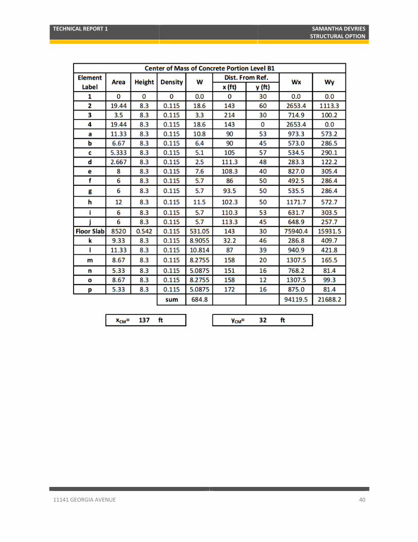
All of the centers of mass for both the steel addition and the concrete portion are very close to
each other when comparing the hand methods to the computer analysis, within a five percent
difference, which shows that the results of the computer analysis verify the center of mass hand
method calculations.
Most of the centers of rigidity are very similar between the hand methods and the computer
analysis, again, mostly within five to ten percent. The center of rigidity of level 1 is very different
between the 2 methods, which may be due to the simplifications made to the hand method
calculations of the basement wall stiffness.

TECHNICAL REPORT 1 SAMANTHA DEVRIES STRUCTURAL OPTION
11141 GEORGIA AVENUE 26
The shear in the frames was compared for a steel moment frame in both the x and y directions
and for a concrete moment frame. The values of shear in frame C are fairly close among both
methods, however the values for frames G and 3 are significantly larger using the hand method
than the computer analysis. This could be due to difference in how the software analysis
distributes the loads among the lateral frames relative to the simplified hand method of
determining relative stiffness and distributing loads. Another reason behind the difference in
values could be related to the effect of the pinned connection at the base of addition.
Ultimately, all three frames followed similar loading patterns between the two methods.

TECHNICAL REPORT 1 SAMANTHA DEVRIES STRUCTURAL OPTION
11141 GEORGIA AVENUE 27
Typical Member Spot Checks for Lateral Loads
Strength checks were completed for a critical column and a beam in the steel addition to the
building. Both the column and the beam come from Frame C. This frame was chosen as a
typical representative steel moment frame and because the shear forces in the frame closely
matched the shear forces found using hand methods. The column strength check takes into
account the combined interaction equations included flexure and compression, where the axial
force was found by adding the axial force due to lateral loading to the force from gravity loads
found in technical report 2. The beam strength check includes a check of shear forces due to
lateral loads and moment due to load combinations including lateral load and gravity loads.
Factored loads will be used in the strength checks.
The following page provides a plan showing Frame C for reference. The column studied is
column C5 at level 6, and the beam being checked is the beam spanning between columns C7
and C8 on level 8.

TECHNICAL REPORT 1 SAMANTHA DEVRIES STRUCTURAL OPTION
11141 GEORGIA AVENUE 28
Figure 3: Plan Showing Lateral Frame Studied in Typical Spot Checks

TECHNICAL REPORT 1 SAMANTHA DEVRIES STRUCTURAL OPTION
11141 GEORGIA AVENUE 29

TECHNICAL REPORT 1 SAMANTHA DEVRIES STRUCTURAL OPTION
11141 GEORGIA AVENUE 30

TECHNICAL REPORT 1 SAMANTHA DEVRIES STRUCTURAL OPTION
11141 GEORGIA AVENUE 31
Appendix
A
B
D
C
E
F
G
H
Steel Moment
Frames

TECHNICAL REPORT 1 SAMANTHA DEVRIES STRUCTURAL OPTION
11141 GEORGIA AVENUE 32
Perimeter Concrete
Moment Frames
1
2 4
3

TECHNICAL REPORT 1 SAMANTHA DEVRIES STRUCTURAL OPTION
11141 GEORGIA AVENUE 33
Note: Building Drawing sets and images pulled from those sets which appear in this report are courtesy of Rathgeber
Goss Association and Bonstra Haresign Architects.
Walls Only on
Level B2
Walls k, l, and
the portion of a
extending from
the box are only
on Level B2 and
B12
a
f
g b
l k
c
i
e
j
h
d
m o
n
p
CMU Shear Walls

TECHNICAL REPORT 1 SAMANTHA DEVRIES STRUCTURAL OPTION
11141 GEORGIA AVENUE 34

TECHNICAL REPORT 1 SAMANTHA DEVRIES STRUCTURAL OPTION
11141 GEORGIA AVENUE 35

TECHNICAL REPORT 1 SAMANTHA DEVRIES STRUCTURAL OPTION
11141 GEORGIA AVENUE 36

TECHNICAL REPORT 1 SAMANTHA DEVRIES STRUCTURAL OPTION
11141 GEORGIA AVENUE 37

TECHNICAL REPORT 1 SAMANTHA DEVRIES STRUCTURAL OPTION
11141 GEORGIA AVENUE 38

TECHNICAL REPORT 1 SAMANTHA DEVRIES STRUCTURAL OPTION
11141 GEORGIA AVENUE 39
TECHNICAL REPORT 1 SAMANTHA DEVRIES STRUCTURAL OPTION
11141 GEORGIA AVENUE 40

TECHNICAL REPORT 1 SAMANTHA DEVRIES STRUCTURAL OPTION
11141 GEORGIA AVENUE 41

TECHNICAL REPORT 1 SAMANTHA DEVRIES STRUCTURAL OPTION
11141 GEORGIA AVENUE 42

TECHNICAL REPORT 1 SAMANTHA DEVRIES STRUCTURAL OPTION
11141 GEORGIA AVENUE 43
TECHNICAL REPORT 1 SAMANTHA DEVRIES STRUCTURAL OPTION
11141 GEORGIA AVENUE 44

TECHNICAL REPORT 1 SAMANTHA DEVRIES STRUCTURAL OPTION
11141 GEORGIA AVENUE 45

TECHNICAL REPORT 1 SAMANTHA DEVRIES STRUCTURAL OPTION
11141 GEORGIA AVENUE 46

TECHNICAL REPORT 1 SAMANTHA DEVRIES STRUCTURAL OPTION
11141 GEORGIA AVENUE 47