Embed Size (px)
Citation preview

Letter of Clarification No. 2 Hammer Lane Widening Phase 3B, Project No. PW1427 June 23, 2016 Page 2
The Engineer will approve the beginning of work disturbing the ground or vegetation between February 15 and August 1.
4. Page 68, Section 9-1.02, “Quantities”: REVISE, the following changes were made:
Item # Description Unit Estimated Quantity
35 Base Failure Repair SF 1,220
82 Thermoplastic Traffic Stripe (Sprayable) LF 22,000
83 Thermoplastic Traffic Stripe LF 5,660
95 Remove Trees EA 75
5. Page 112, Section 20-1.01A, “Cost Breakdown”:
DELETE “Remove Trees” and its quantity from the Street Planting Cost Breakdown. A Bid Item was created for this quantity.
6. Page 112, Section 20-1.01A, “Cost Breakdown”:
DELETE “Stamped Concrete” and its quantity from the Street Planting Cost Breakdown. Stamped Concrete is Bid Item 73.
7. Page 138, Section 39-1.03, “Hot Mix Asphalt”: CHANGE the last paragraph to read: Full compensation for conforming to the requirements of this provision, furnishing all labor, materials (including roadway pavement aggregate base), tools, equipment and incidentals and for doing all the work involved in installing Hot Mix Asphalt shall be considered as included in the unit price paid per ton for “Hot Mix Asphalt (Type A)” as adjusted herein, and no additional compensation will be allowed therefor. No additional compensation will be paid to the Contractor if the bitumen ratio in the approved mix design increases or decreases the amount of asphalt binder assumed in preparing the Contractor’s bid.
8. Page 145, Section 73-1.01, “Concrete Curbs, Gutters and Sidewalks”: CHANGE the first paragraph to read:
Letter of Clarification No. 2 Hammer Lane Widening Phase 3B, Project No. PW1427 June 23, 2016 Page 3
Concrete curb, gutter, sidewalk, curb return, wheelchair ramp, controller walkway, retaining curb, concrete header, stamped concrete, commercial and residential driveway and Portland cement concrete flat work shall conform to the provisions in Section 73, "Concrete Curbs and Sidewalks," and Section 90, “Concrete” of the Caltrans Standard Specifications and these special provisions. All concrete used in constructing these items shall be Class 2 Portland cement concrete per Section 90 of the Caltrans Standard Specifications.
9. Page 145, Section 73-1.01, “Concrete Curbs, Gutters and Sidewalks”: CHANGE the fifth paragraph to read: For the concrete header, Contractor shall provide a light broom finish with strokes perpendicular to direction of band.
10. Page 145, Section 73-1.01, “Concrete Curbs, Gutters and Sidewalks”: CHANGE the sixth paragraph to read: For stamped concrete within the roadway median, imprint pattern shall be “Octagon Paver” with Limestone Sandblast texture as available from Bomanite, 8777 Auburn Folsom Rd., #108, Granite Bay, CA 95746, (303) 369-1115. Integral color admixture shall be “Mexican Tile” available from Bomanite. Mix integral color at a rate per manufacturer’s specifications. The stamped and colored concrete used for driveway conforms, imprint pattern and color shall match the existing. Driveway conforms (including stamped and colored concrete) are included in the “Residential/Commercial Driveway” bid item.
11. Page 145, Section 73-1.01, “Concrete Curbs, Gutters and Sidewalks”: CHANGE the last paragraph to read: Full compensation for furnishing all labor, materials (including aggregate base), tools, equipment and incidentals, traffic control, and doing all work involved in installing various items of work shall be considered as included in the contract prices paid per lineal for “Vertical Curb and Gutter”, “Roll Type Curb and Gutter”, “Concrete Header”, “Type “C” Vertical Curb”, “Type “D” Vertical Curb”, “Type “E” Vertical Curb”, “Median Curb (Type 4)”, “Median Curb (Type 4A)”, “Retaining Curb”, per unit for “Wheelchair Ramps”, and per square foot for “Sidewalk”, “Stamped Concrete”, “Residential/Commercial Driveway”, and “Controller Walkway,” and no additional compensation will be allowed therefor.
Letter of Clarification No. 2 Hammer Lane Widening Phase 3B, Project No. PW1427 June 23, 2016 Page 4
12. Pages 150 through 153, Section 84-1.01, “Thermoplastic Traffic Stripe
(Sprayable), Section 84-1.02, “Thermoplastic Traffic Stripe and Pavement Marking” and Section 84-1.03, “Pavement Markers”: REPLACE these sections with the following: 84-1.01 Traffic Stripes, Pavement Markings, and Pavement Markers Traffic stripes and pavement legends, including crosswalks, shall be placed as shown on the plans, as specified in the California MUTCD and Sections 84, "Markings of the Caltrans Specifications, as modified herein, and as directed by the Engineer. All pavement traffic stripes, legends, arrows and crosswalks shall be installed with hot applied thermoplastic pavement material. The thermoplastic material shall be free of lead and chromium and conform to State Specification PTH-02ALKYD (for markings) and PTH-02SPRAY (for stripes). Thermoplastic material shall be applied to the pavement at a minimum thickness of 0.060 inches for long lines (4 inches stripes and 8 inches stripes in width) and 0.100 inches for all legends and arrows. The crosswalk lines and limit lines shall be installed at a minimum thickness of 0.125 inches. A double extruded thermoplastic traffic stripe consisting of two 4-inch wide stripes is measured as 2 traffic stripes. A double sprayable thermoplastic traffic stripe consisting of two 4-inch wide stripes is measured as 1 traffic stripe. If the contractor chooses to install stripes by using a cart (extruded) rather than a striping vehicle, all striping shall be applied to the pavement at a minimum thickness of 0.090 inches. Glass beads shall conform to State Specification 8010-004 dated December 22, 2009. Thermoplastic pavement markings and stripes shall be free of runs, bubbles, craters, drag marks, stretch marks, and debris. Use appropriate installation procedures according to manufacturer. If pavement markings are applied to existing surface over existing painted legends (arrows and crosswalks), existing pavement legends (arrows and sidewalks) shall be removed before thermoplastic material is applied. For either material, pavement shall be preheated to remove all residual moisture prior to installation.
Letter of Clarification No. 2 Hammer Lane Widening Phase 3B, Project No. PW1427 June 23, 2016 Page 5
At intersections where existing pavement is removed and replaced, Contractor shall install new crosswalk control points for the City Traffic Engineering Department to review and approve. Configuration of traffic stripes, pavement markings, and crosswalks shall conform to the detail and methods as set forth in the latest issue of the State of California MUTCD and Caltrans Specifications, unless specifically modified on the plans. All existing traffic stripes and pavement markings shall be removed where shown on the plans, where the existing striping conflicts with proposed striping, and as designated by the Engineer. Existing pavement markers, including underlying adhesive, when no longer required for traffic lane delineation, as directed by the Engineer, shall be removed and disposed of. Removal of traffic stripes and pavement markings, or the removal of objectionable material, shall be performed using methods approved in advance by the Engineer. All resulting residue and dust shall be removed immediately from the surface being treated. Such removal shall be by a vacuum attachment operating concurrently with the blast cleaning operation. The removal of yellow paint and thermoplastic material shall be considered as Hazardous Waste Residue. The removal of yellow paint and thermoplastic material shall include testing for lead prior to disposal of the material. Disposal of materials containing lead shall conform to state approved practices. Work associated with the testing and disposal of the thermoplastic material shall be paid for as extra as provided in Section 5-1.14 “Extra Work” of these special provisions. The Contractor shall place control points for the Engineer to review and approve. No additional "cat tracks" shall be placed until control points are approved by the Engineer. The Contractor shall obtain approval from the Engineer on all striping cat tracks prior to final application and striping and markers. The Contractor shall place and remove any temporary striping required for routing traffic through the project area. All thermoplastic shall be provided by the Contractor. Manufacturer and specifications shall be submitted for approval and shall conform to the specifications contained herein. All thermoplastic supplied shall conform to the local air pollution regulations. Traffic line markings shall be reflectorized and shall
Letter of Clarification No. 2 Hammer Lane Widening Phase 3B, Project No. PW1427 June 23, 2016 Page 6
conform to the Caltrans Specifications, Section 84-2,”Thermoplastic Traffic Stripes and Pavement Markings”. Existing surface which is to receive the thermoplastic material shall be mechanically wire brushed to remove all dirt and contaminants. Thermoplastic material shall be applied only to the dry pavement surfaces and only when the pavement surface temperature is above fifty (50°F) degrees Fahrenheit. Thermoplastic shall be applied only on a thoroughly dry surface and during periods of favorable weather. The Contractor shall make all necessary conform striping as required. The completed stripes and markings shall be sharp and clear with clean, well-defined edges. Any damage by the elements to the newly stripe or marking due to the failure of any Contractor to protect his work shall be repaired by him at no additional cost. Any over-spray or tracking of fresh thermoplastic material onto unpainted surfacing shall be removed by any methods to the satisfaction of the Engineer. On one-way streets and median-divided streets, the side of the retroreflective raised pavement markers that is visible to traffic proceeding in the wrong direction shall be red. The other retroreflective side shall be white or yellow as per the detail. This section is applicable to Details 9, 10, 12, 13, 25, 25A, 26 and 27. Blue Raised Pavement Markers shall be installed after any surface treatment (overlay, micro-surfacing, chip-seal, cape-seal, etc.) solely for aiding in locating fire hydrants. (1) Two-Way Streets—Markers should be placed 6 inches from the edge of painted centerline on the side nearest the fire hydrant. If the street has no centerline, the marker should be placed 6 inches from the approximate center of the roadway on the side nearest the hydrant. (2) Streets with Left Turn Lane at Intersection—Markers should be placed 6 inches from the edge of painted white channelizing line on the side nearest the hydrant. (3) Streets with Continuous Two-Way Turn Lane—Markers should be placed 6 inches from the edge of the painted yellow barrier line on the side nearest the fire hydrant.
Letter of Clarification No. 2 Hammer Lane Widening Phase 3B, Project No. PW1427 June 23, 2016 Page 7
(4) One-way streets and median-divided streets—Markers should be placed 6 inches from the edge of lane line on the side nearest the fire hydrant (at least 12’ from curb or edge of traveled way). Typical marker locations are shown on Figure 3B-102 (CA) of California MUTCD. The contract price paid per lineal foot for Thermoplastic Traffic Stripe and square foot for Thermoplastic Pavement Marking shall include full compensation for furnishing all labor, materials, tools, equipment and incidentals, and for doing all the work involved in removing and applying Thermoplastic Traffic Stripes (regardless of the number, widths, and patterns of individual stripes involved in each traffic stripe) and pavement markings including establishing alignment for stripes and layout work, complete in place, as shown on the plans, as specified in the Standard Specifications and these Special Provisions, and as directed by the Engineer.
13. Page 153, Section 84-1.04 “General”. DELETE Materials header and paragraph.
14. Page 172, Section 86-2.19 “Detectors”. ADD the following to the section: Multi-Sensor (Video Imaging and Radar) Vehicle Detection System 1. General
This specification sets forth the minimum requirements for a system that detects vehicles on a roadway using a multi-sensor detection system. The multi-sensor system shall utilize two different sensors of different technologies, video imaging and radar, to detect and track licensed and unlicensed vehicles at distances up to 600 feet (180 meters). The sensor system shall fuse vehicle information from the two sensors to provide highly accurate and precise detection for special or advanced applications. The multi-sensor system shall use a primary detector rack mounted processor to interface with the traffic control cabinet. The module shall process information from both video imaging and radar sensors simultaneously in real-time. 1.1 System Configurations
Letter of Clarification No. 2 Hammer Lane Widening Phase 3B, Project No. PW1427 June 23, 2016 Page 8
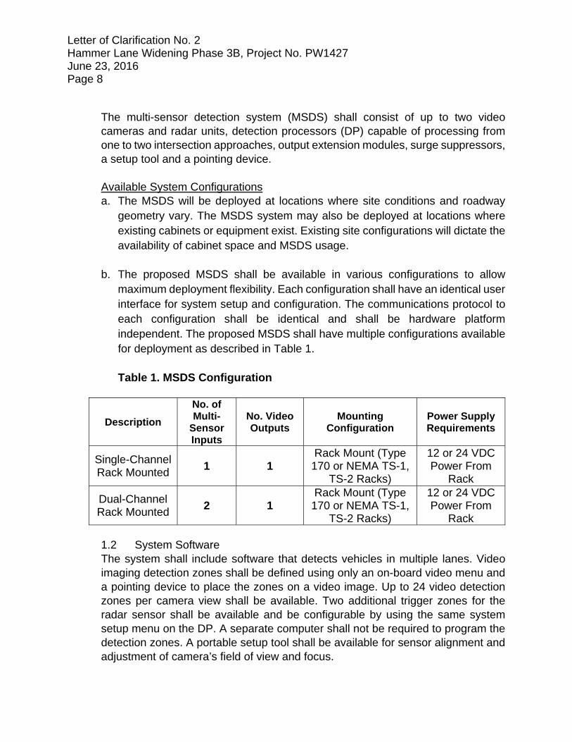
The multi-sensor detection system (MSDS) shall consist of up to two video cameras and radar units, detection processors (DP) capable of processing from one to two intersection approaches, output extension modules, surge suppressors, a setup tool and a pointing device. Available System Configurations a. The MSDS will be deployed at locations where site conditions and roadway
geometry vary. The MSDS system may also be deployed at locations where existing cabinets or equipment exist. Existing site configurations will dictate the availability of cabinet space and MSDS usage.
b. The proposed MSDS shall be available in various configurations to allow
maximum deployment flexibility. Each configuration shall have an identical user interface for system setup and configuration. The communications protocol to each configuration shall be identical and shall be hardware platform independent. The proposed MSDS shall have multiple configurations available for deployment as described in Table 1. Table 1. MSDS Configuration
Description
No. of Multi-
Sensor Inputs
No. Video Outputs
Mounting Configuration
Power Supply Requirements
Single-Channel Rack Mounted
1 1 Rack Mount (Type 170 or NEMA TS-1,
TS-2 Racks)
12 or 24 VDC Power From
Rack
Dual-Channel Rack Mounted
2 1 Rack Mount (Type 170 or NEMA TS-1,
TS-2 Racks)
12 or 24 VDC Power From
Rack 1.2 System Software The system shall include software that detects vehicles in multiple lanes. Video imaging detection zones shall be defined using only an on-board video menu and a pointing device to place the zones on a video image. Up to 24 video detection zones per camera view shall be available. Two additional trigger zones for the radar sensor shall be available and be configurable by using the same system setup menu on the DP. A separate computer shall not be required to program the detection zones. A portable setup tool shall be available for sensor alignment and adjustment of camera’s field of view and focus.
Letter of Clarification No. 2 Hammer Lane Widening Phase 3B, Project No. PW1427 June 23, 2016 Page 9
2. Multi-Sensor Detection System Hardware
The MSDS hardware shall consist of the following four elements: a. Video imaging camera sensor b. Radar sensor c. Sensor data combiner d. Detection processor 2.1 Video Imaging Camera Sensor To accommodate deployment flexibility, the MSDS camera sensor shall be compatible will all DP platforms identified in Table 1. The MSDS camera sensor shall be supplied by the MSDS manufacturer.
2.1.1 The advanced camera enclosure shall utilize Indium Tin Oxide (ITO) technology for the heating element of the front glass. The transparent coating shall not impact the visual acuity and shall be optically clear.
2.1.2 Cable terminations at the data combiner for video and power shall not
require crimping or special tools.
2.1.3 The camera sensor shall allow the user to set the focus and field of view via Wi-Fi connectivity.
2.1.4 The camera shall produce a useable video image of the bodies of
vehicles under all roadway lighting conditions, regardless of time of day. The minimum range of scene luminance over which the camera shall produce a useable video image shall be the minimum range from nighttime to daytime, but not less than the range 1.0 lux to 10,000 lux.
2.1.5 The camera electronics shall include automatic gain control (AGC) to
produce a satisfactory image at night.
2.1.6 The imager luminance signal-to-noise ratio (S/N) shall be more than 50 dB with the automatic gain control (AGC) disabled.
2.1.7 The imager shall employ three dimensional dynamic noise reduction
(3DDNR) to remove unwanted image noise.

Letter of Clarification No. 2 Hammer Lane Widening Phase 3B, Project No. PW1427 June 23, 2016 Page 10
2.1.8 The camera imager shall employ wide dynamic range (WDR) technology to compensate for wide dynamic outdoor lighting conditions. The dynamic range shall be greater than 100 dB.
2.1.9 The camera shall be digital signal processor (DSP) based and shall use
a CCD sensing element and shall output color video with resolution of not less than 550 TV lines. The color CCD imager shall have a minimum pixel count of 380K (NTSC) / 440K (PAL).
2.1.10 The camera sensor shall include an electronic shutter control based
upon average scene luminance and shall be equipped with an auto-iris lens that operates in tandem with the electronic shutter. The electronic shutter shall operate between the ranges of 1/4 to 1/10,000th second.
2.1.11 The camera sensor shall utilize automatic white balance.
2.1.12 The camera sensor shall include a variable focal length lens with
variable focus that can be adjusted, without opening up the camera housing, to suit the site geometry by means of a portable interface device designed for that purpose and manufactured by the detection system supplier.
2.1.13 The horizontal field of view shall be adjustable from 4.6 to 53.6 degrees.
This camera configuration may be used for the majority of detection approaches in order to minimize the setup time and spares required by the user. The lens shall be a 12x zoom lens with a focal length of 3.7mm to 44.0mm.
2.1.14 The lens shall also have an auto-focus feature with a manual override
to facilitate ease of setup.
2.1.15 The camera shall incorporate the use of preset positioning that store zoom and focus positioning information. The camera shall have the capability to recall the previously stored preset upon application of power.
2.1.16 The camera shall be housed in a weather-tight sealed enclosure
conforming to IP-67 specifications. The housing shall allow the camera
Letter of Clarification No. 2 Hammer Lane Widening Phase 3B, Project No. PW1427 June 23, 2016 Page 11
to be rotated to allow proper alignment between the camera and the traveled road surface.
2.1.17 Recommended camera placement height shall be 18-33 feet (or 6-10
meters) above the roadway, and over the traveled way on which vehicles are to be detected. For optimum detection the camera should be centered above the traveled roadway. The camera shall view approaching vehicles at a distance not to exceed 350 feet (107 meters) for reliable detection (height to distance ratio of 10:100). Camera placement and field of view (FOV) shall be unobstructed and as noted in the installation documentation provided by the supplier.
2.1.18 The video signal shall be fully isolated from the camera enclosure and
power cabling.
2.1.19 A weather-proof protective cover shall be provided to protect all terminations at the camera.
2.1.20 The camera enclosure shall be equipped with a sunshield. The
sunshield shall include a provision for water diversion to prevent water from flowing in the camera's field of view.
2.1.21 The camera enclosure shall be design so that the pan, tilt and rotation
of the camera assembly can be accomplished independently without affecting the other settings.
2.1.22 The camera enclosure shall include a proportionally controlled Indium
Tin Oxide heater design that maximizes heat transfer to the lens. The output power of the heater shall vary with temperature, to assure proper operation of the lens functions at low temperatures and prevent moisture condensation on the optical faceplate of the enclosure.
2.1.23 The glass face on the front of the enclosure shall have an anti-reflective
coating to minimize light and image reflections.
2.1.24 When mounted outdoors in the enclosure, the camera shall operate in a temperature range from -30 o F to +165 o F (-34 °C to +74 °C) and a humidity range from 0% RH to 100% RH. Measurement of satisfactory video shall be based upon DP system operation.
Letter of Clarification No. 2 Hammer Lane Widening Phase 3B, Project No. PW1427 June 23, 2016 Page 12
2.1.25 The camera sensor shall acquire its power from the sensor data
combiner. 2.2 Radar Sensor
2.2.1 The radar sensor shall operate in the 24 GHz frequency band and shall operate on 1 of 7 available enumerated channels that is user selectable.
2.2.2 The radar detection range shall be 600 feet (180 meters) minimum, +/-
5%.
2.2.3 The radar sensor shall be able to track up to 20 independent objects simultaneously.
2.2.4 Object speed detection shall be within a range of 0 to 150 miles per hour
+/- 1.0 miles per hour (240 km per hour ± 1.5 km per hour).
2.2.5 The radar sensor shall be able to detect vehicles in 1 to 4 traffic lanes.
2.2.6 The radar sensor shall be housed in a weather-tight sealed enclosure conforming to IP-67 specifications. The housing shall allow the radar to be adjusted to allow proper alignment between the sensor and the traveled road surface.
2.2.7 When mounted outdoors in the enclosure, the radar shall operate in a
temperature range from -30 o F to +165 o F (-34 °C to +74 °C) and a humidity range from 0% RH to 100% RH.
2.2.8 The radar sensor shall communicate with the sensor data combiner.
2.2.9 The radar sensor shall acquire its power from the sensor data combiner.
2.3 Multi-Sensor Assembly
2.3.1 Both camera and radar sensors shall be housed in an overall, single enclosure assembly.
2.3.2 The overall size of the multi-sensor enclosure shall not exceed 14 inches
x 15 inches x 17 inches (355mm x 380mm x 430mm).

Letter of Clarification No. 2 Hammer Lane Widening Phase 3B, Project No. PW1427 June 23, 2016 Page 13
2.3.3 The overall weight of the multi-sensor unit shall not exceed 11 pounds (5kg).
2.3.4 The effective projected area (EPA) shall not exceed 2.0 square feet (0.6
square meters).
2.3.5 The maximum power consumption for the multi-sensor assembly shall be less than 10 watts typical, 20 watts peak.
2.4 Sensor Data Combiner
2.4.1 A sensor data combiner that combines sensor information from both video and radar sensors shall be employed.
2.4.2 The sensor data combiner shall supply primary power to each sensor
unit.
2.4.3 The sensor data combiner shall facilitate digital communications between the sensor data combiner and each of the sensor units.
2.4.4 The sensor data combiner shall get its primary power from an AC power
source using industry standard 3-conductor cabling.
2.4.5 The sensor data combiner shall communicate with the detection processor using a single coax cable. Both video imaging and radar data shall use the single coax cable.
2.4.6 The sensor data combiner shall also employ industry standard Wi-Fi
connectivity for remote sensor system setup using a mobile programming device such as a netbook or tablet computer. Video camera and radar sensor shall be able to be configured independently.
2.4.7 The sensor data signal shall be fully isolated from the mechanical
enclosure and power cabling.
2.4.8 Cable terminations at the sensor data combiner shall not require crimping tools.
2.4.9 The sensor data combiner shall be housed in a weather-tight sealed
enclosure conforming to IP-67 specifications.
Letter of Clarification No. 2 Hammer Lane Widening Phase 3B, Project No. PW1427 June 23, 2016 Page 14
2.5 Detection Processor
2.5.1 Each sensor input shall accept RS170 (NTSC) or CCIR (PAL) signals from an external video source. The interface connector shall be BNC type and shall be located on the front of the processing unit. The sensor input shall have the capability to be terminated into 75-ohms or high impedance (Hi-Z) using dip switches or software control from the user menu. The sensor input shall also facilitate the data from the radar sensor.
2.5.2 A LED indicator shall be provided to indicate the presence of the sensor
signal. The LED shall illuminate upon valid sensor synchronization and turn off when the presence of a valid sensor signal is removed.
2.5.3 One video output shall be provided. The video output shall be RS170 or
CCIR compliant and shall pass through the input video signal. For multichannel video input configurations, a momentary push-button shall be provided on the front panel to cycle through each input video channel. In the absence of a valid sensor signal, the channel shall be skipped and the next valid sensor signal shall be switched. The real time video output shall have the capability to show text and graphical overlays to aid in system setup. The overlays shall display real-time actuation of detection zones upon vehicle detection or presence. Overlays shall be able to be turned off by the user. Control of the overlays and sensor switching shall also be provided through the serial communications port. The video output interface connector shall be positive locking BNC type. Friction type (e.g. RCA type) connectors shall not be allowed.
2.5.4 A serial communications port shall be provided on the front panel. The
serial port shall compliant with EIA232 electrical interfaces and shall use a DB9 type connector mounted on the front panel of the DP. The serial communications interface shall allow the user to remotely configure the system and/or to extract calculated vehicle/roadway information. The interface protocol shall be documented or interface software shall be provided. The interface protocol shall support multi-drop or point-to-multipoint communications. Each MSDS shall have the capability to be addressable. The DP shall support data rates of 1200 bps to 230,400 bps, inclusive.

Letter of Clarification No. 2 Hammer Lane Widening Phase 3B, Project No. PW1427 June 23, 2016 Page 15
2.5.5 Open collector (contact closure) outputs shall be provided. Four (4) open collector outputs shall be provided for the single or dual channel rack-mount configuration. Additionally, the DP shall allow the use of extension modules to provide up to 24 open collector contact closures per camera input. Each open collector output shall be capable of sinking 30 mA at 24 VDC. Open collector outputs will be used for vehicle detection indicators as well as discrete outputs for alarm conditions. The DP outputs shall be compatible with industry standard detector racks assignments.
2.5.6 Logic inputs such as delay/extend or delay inhibit shall be supported
through the appropriate detector rack connector pin or front panel connector in the case of the I/O module. For DPs and extension modules, 4 inputs shall be supported via detector rack interface. The I/O module shall accommodate eight (8) inputs through a 15-pin “D” connector.
2.5.7 Detection status LEDs shall be provided on the front panel. The LEDs
shall illuminate when a contact closure output occurs. Rack-mounted detection processors shall have a minimum of four (4) LEDs. Rack-mounted extension modules shall have two (2), four (4) or eight (8) LEDs (depending upon extension module type) to indicate detection.
2.5.8 The front panel of the DP shall have detector test switches to allow the
user to manually place calls on each DP output channel. The test switch shall be able to place either a constant call or a momentary call depending on the position of the switch.
2.5.9 A USB mouse port shall be provided on the front panel of the rack mount
detection processing unit. The mouse port shall not require special mouse software drivers. The mouse port shall be used as part of system setup and configuration. A mouse shall be provided with each detection processor.
2.5.10 Extension modules shall be connected to the DP by an 8-wire twisted-
pair cable with modular RJ45 connectors. DP and EM communications shall be accommodated by methods using differential signals to reject electrically coupled noise.
Letter of Clarification No. 2 Hammer Lane Widening Phase 3B, Project No. PW1427 June 23, 2016 Page 16
2.5.11 Extension modules (EM) shall be available to eliminate the need of rewiring the detector rack, by enabling the user to plug an extension module into the appropriate slot in the detector rack to provide additional open collector outputs. The extension module shall be available in both 2 and 4 channel configurations. EM configurations shall be programmable from the DP. A separate I/O module with 32 outputs through a 37-pin “D” connector on the front panel and 8 inputs through a 15-pin “D” connector using an external wire harness for expanded flexibility shall also be available.
2.5.12 The DP and EM shall be specifically designed to mount in a standard
detector rack, using the edge connector to obtain power, provide contact closure outputs and accept logic inputs (e.g. delay/extend). No adapters shall be required to mount the DP or EM in a standard detector rack. Detector rack rewiring shall not be required.
2.5.13 The DP shall utilize non-volatile memory technology to store on-board
firmware and operational data.
2.5.14 The DP shall enable the loading of modified or enhanced software through the EIA232 or USB port (using a USB thumb drive) and without modifying the DP hardware.
2.5.15 The DP and EM shall be powered by 12 or 24 volts DC. DP and EM
modules shall automatically compensate for either 12 or 24 VDC operation. DP power consumption shall not exceed 7.5 watts. The EM power consumption shall not exceed 3 watts.
2.5.16 The DP shall operate satisfactorily in a temperature range from -30 o F
to +165 o F (-34 °C to +74 °C) and a humidity range from 0%RH to 95%RH, noncondensing as set forth in NEMA specifications.
2.5.17 An Edco CX-06M video surge suppresser shall be provided for each
sensor input. The surge suppresser shall be appropriately grounded to the cabinet ground rod using 14 AWG wire (2.5 mm2 ) minimum.
Letter of Clarification No. 2 Hammer Lane Widening Phase 3B, Project No. PW1427 June 23, 2016 Page 17
3. System Software 3.1 General System Functions
3.1.1 Detection zones shall be programmed via an on board menu displayed on a video monitor and a pointing device connected to the DP. The menu shall facilitate placement of detection zones and setting of zone parameters or to view system parameters. A separate computer shall not be required for programming detection zones or to view system operation.
3.1.2 The DP shall store up to three different detection zone patterns in non-
volatile memory. The DP can switch to any one of the three different detection patterns within 1 second of user request via menu selection with the pointing device. Each configuration shall be uniquely labeled and able to be edited by the user for identification. The currently active configuration indicator shall be displayed on the monitor.
3.1.3 The DP shall detect vehicles in real time as they travel across each
detection zone.
3.1.4 The DP shall accept new detection patterns from an external computer through the EIA232 port when the external computer uses the correct communications protocol for downloading detection patterns. A Windows™- based software designed for local or remote connection and providing video capture, real-time detection indication and detection zone modification capability shall be provided with the system.
3.1.5 The DP system shall have the capability to automatically switch to any
one of the stored configurations based on the time of day which shall be programmable by the user.
3.1.6 The DP shall send its detection patterns to an external computer through
the EIA232 port when requested when the external computer uses the appropriate communications protocol for uploading detection patterns.
Letter of Clarification No. 2 Hammer Lane Widening Phase 3B, Project No. PW1427 June 23, 2016 Page 18
3.1.7 The DP shall default to a safe condition, such as a constant call on each active detection channel, in the event of unacceptable interference or loss of the sensor signal.
3.1.8 The system shall be capable of automatically detecting a low-visibility
condition such as fog and respond by placing all effected detection zones in a constant call mode. A user-selected alarm output shall be active during the low-visibility condition that can be used to modify the controller operation if connected to the appropriate controller input modifier(s). The system shall automatically revert to normal detection mode when the low-visibility condition no longer exists.
3.1.9 Up to 24 detection zones per camera input shall be supported and each
detection zone can be sized to suit the site and the desired vehicle detection region.
3.1.10 The DP shall provide up to 24 open collector output channels per sensor
input using one or more extension modules.
3.1.11 A single detection zone shall be able to replace multiple inductive loops and the detection zones shall be OR'ed as the default or may be AND'ed together to indicate vehicle presence on a single approach of traffic movement.
3.1.12 Placement of detection zones shall be done by using only a pointing
device, and a graphical interface built into the DP and displayed on a video monitor, to draw the detection zones on the video image from each video camera. No separate computer shall be required to program the detection zones.
3.1.13 When a vehicle is detected within a detection zone, a visual indication
of the detection shall activate on the video overlay display to confirm the detection of the vehicle for the zone.
3.1.14 Detection shall be at least 98% accurate in good weather conditions,
with slight degradation possible under adverse weather conditions (e.g. rain, snow, or fog) which reduce visibility. Detection accuracy is dependent upon site geometry, camera placement, camera quality and
Letter of Clarification No. 2 Hammer Lane Widening Phase 3B, Project No. PW1427 June 23, 2016 Page 19
detection zone location, and these accuracy levels do not include allowances for occlusion or poor video due to camera location or quality.
3.1.15 The DP shall provide dynamic zone reconfiguration (DZR). DZR enables
normal operation of existing detection zones when one zone is being added or modified during the setup process. The new zone configuration shall not go into effect until the configuration is saved by the operator.
3.1.16 Detection zone setup shall not require site specific information such as
latitude and longitude to be entered into the system.
3.1.17 The DP shall process the video input from each camera at 30 frames per second. Multiple camera processors shall process all video inputs simultaneously.
3.1.18 The DP shall output a constant call during the background learning
period of no more than 3 minutes.
3.1.19 Detection zone outputs shall be configurable to allow the selection of presence, pulse, extend, and delay outputs. Timing parameters of pulse, extend, and delay outputs shall be user definable between 0.1 to 25.0 seconds.
3.1.20 Up to six video detection zones per sensor input shall have the capability
to count the number of vehicles detected. The count value shall be internally stored for later retrieval through the EIA232 port. The zone shall also have the capability to calculate and store average speed and lane occupancy at bin intervals of 10 seconds, 20 seconds, 1 minute, 5 minutes, 15 minutes, 30 minutes and 60 minutes. One radar sensor zone shall also count vehicles, calculate, and store the average speed and lane occupancy across the approach.
3.1.21 In addition to the count type zone, the DP shall be able to calculate
and/or acquire average speed and lane occupancy using both video and radar sensors. These values shall be stored in non-volatile memory for later retrieval.
3.1.22 The DP shall have an “advance” zone type where detection outputs to
the traffic controller is compensated for angular occlusion and distance.

Letter of Clarification No. 2 Hammer Lane Widening Phase 3B, Project No. PW1427 June 23, 2016 Page 20
3.1.23 The DP shall support bicycle type zones where the zone can
differentiate between motorized vehicles and bicycles, producing a call for one but not the other.
3.1.24 Bicycle zone types shall only output when a bicycle is detected. Larger
motorized vehicles such as cars and trucks that traverse a bicycle zone shall not provide an output.
3.1.25 Six additional count zones for bicycles, separate from the 6 data
collection zones for vehicles, shall be provided to accumulate bicycle counts at user specified intervals.
3.1.26 Bicycle zones shall have the ability to have extensions assigned to
individual bicycle zones for applications where the traffic controller does not have bicycle specific detection inputs.
3.1.27 The DP shall provide the ability to assign a separate output channel for
bicycle zones to allow traffic controllers to implement special bicycle timing for applications where the traffic controller has separate bicycle detection inputs.
3.1.28 The DP shall employ color overlays on the video output.
3.1.29 The DP shall have the ability to show phase status (green, yellow, or
red) for up to 8 phases. These indications shall also be color coded.
3.1.30 The user shall have the ability to enable or disable the display of the phase information on the video output.
3.1.31 The DP shall have the capability to change the characteristics of a
detection zone based on external inputs such as signal phase. Each detection zone shall be able to switch from one zone type (i.e. presence, extension, pulse, etc.) to another zone type based on the signal state. For example, a zone may be a “count” zone when the phase is green but change to a “presence” zone type when the phase is not green. Another application would be zone type of “extension” when the signal phase is green and then “delay” when red.
Letter of Clarification No. 2 Hammer Lane Widening Phase 3B, Project No. PW1427 June 23, 2016 Page 21
3.1.32 For alpha numeric user inputs, the DP shall utilize a virtual keyboard on the video overlay system to ease user input. The virtual keyboard shall use the standard QWERTY keyboard layout.
3.1.33 The DP shall aid the user in drawing additional detection zones by
automatically drawing and placing zones at appropriate locations with only a single click of the mouse. The additional zone shall utilize geometric extrapolation of the parent zone when creating the child zone. The process shall also automatically accommodate lane marking angles and zone overlaps.
3.1.34 When the user wishes to modify the location of a zone, the DP shall
allow the user move a single zone, multiple zones or all zones simultaneously.
3.1.35 When the user wishes to modify the geometric shape of the zone, the
DP shall allow the user to change the shape by moving the zone corner or zone sides.
3.1.36 On screen zone identifiers shall be modifiable by the user. The user shall
be allowed to select channel output assignments, zone type, input status, zone labels or zone numbers to be the identifier.
3.1.37 For multiple camera input DPs, the user shall have the ability to enable
automatic video output switching. The dwell time for each sensor input shall be user programmable.
3.1.38 The DP shall support 3 independent trigger points for radar outputs for
standard dilemma zone applications.
3.1.39 For radar sensor zones, the output can be triggered by presence of a vehicle only or by presence of a vehicle above a user-defined speed threshold.
3.1.40 The radar sensor system shall also provide a platoon detection or
“group” detection and provide a user-definable output when a minimum specified number of vehicles are detected in the region of interest.
Letter of Clarification No. 2 Hammer Lane Widening Phase 3B, Project No. PW1427 June 23, 2016 Page 22
3.1.41 The system shall provide a method of providing a continuous output for dynamic dilemma zone applications where each individual vehicle is tracked and an output is provided only when the vehicle is within dilemma zone parameters.
3.1.42 The system shall provide the ability to provide a user-definable output in
a continuous mode when specific, continuously monitored, distance and speed parameters of vehicles are met.
3.1.43 In the continuous mode, the user shall have the ability to define the
region of interest by providing a minimum distance and maximum distance parameters for the region of interest.
3.1.44 In the continuous mode and within the region of interest, the user shall
have the ability to define the minimum speed and maximum speed thresholds for both the minimum and maximum distances.
3.1.45 In the continuous mode, no output shall be provided if vehicles do not
meet the parameters of the dynamic dilemma zone detection application.
4. Installation 4.1 General
4.1.1 The coaxial cable to be used between the multi-sensor assembly and the DP in the traffic cabinet shall be Belden 8281. This cable shall be suitable for installation in conduit or overhead with appropriate span wire. BNC plug connectors shall be used where applicable. The coaxial cable, BNC connector, and crimping tool shall be approved by the supplier of the MSDS, and the manufacturer's instructions must be followed to ensure proper connection.
4.1.2 The power cabling shall be 16 AWG (1.0 mm2 ) three-conductor cable
with a minimum outside diameter of 0.325 inch (8.25 mm) and a maximum diameter of 0.490 inch (12.45 mm). The cabling shall comply with the National Electric Code, as well as local electrical codes. Cameras may acquire power from the luminaire if necessary.
Letter of Clarification No. 2 Hammer Lane Widening Phase 3B, Project No. PW1427 June 23, 2016 Page 23
4.1.3 The MSDS shall be installed by factory-certified installers and shall be IMSA Level II Traffic Signal Technician certified. Proof of certifications shall be provided.
4.2 Setup Tool
4.2.1 A set up tool shall be provided for the MSDS. The setup tool will provide secure access to the Sensor Data Combiner. The secure access will be on two levels; the first is a ten digit hexadecimal WiFi key embedded in the setup tool. The second is a user selectable alphanumeric password of between four and ten digits.
4.2.2 The setup tool shall provide the following Video Image Camera Sensor
functions; Zoom and auto focus adjustments, low frame rate video and image snapshot storage functions.
4.2.3 The setup tool shall provide the following Radar Sensor functions;
height, operating channel and sensor offset adjustments. The setup tool shall provide a visualization of the roadway with icons representing vehicles at the approach along with simulated detector outputs and instantaneous vehicle speed. The icon will be one of three sizes representing the classification of the vehicle. The detector trigger points shall be user adjustable along with the stop bar to MSDS distance.
4.2.4 The setup tool shall provide other general functions; MSDS labeling,
password setting and Sensor Data Combiner firmware upgrades.
4.2.5 The set up tool shall be provided on a personal computer having an embedded Wi-Fi module running at 2.4 GHz ISM band.
4.2.6 The set up tool shall be provided on a tablet computer having an
embedded Wi-Fi module running at 2.4 GHz ISM band.
5. Warranty 5.1 The supplier shall provide a limited three-year warranty on the MSDS. 5.2 During the warranty period, technical support shall be available from the
supplier via telephone within 4 hours of the time a call is made by a user,

Letter of Clarification No. 2 Hammer Lane Widening Phase 3B, Project No. PW1427 June 23, 2016 Page 24
and this support shall be available from factory-certified personnel or factory certified installers.
5.3 During the warranty period, updates to DP software shall be available from
the supplier without charge. 6. Maintenance and Support 6.1 The supplier shall maintain an adequate inventory of parts to support
maintenance and repair of the MSDS. These parts shall be available for delivery within 30 days of placement of an acceptable order at the supplier's then current pricing and terms of sale for said parts.
6.2 The supplier shall maintain an ongoing program of technical support for the
MSDS. This technical support shall be available via telephone, or via personnel sent to the installation site upon placement of an acceptable order at the supplier's then current pricing and terms of sale for on site technical support services.
6.3 Installation or training support shall be provided by a factory-authorized
representative and shall be a minimum IMSA-Level II Traffic Signal Technician certified.
6.4 All product documentation shall be written in the English language.
IMPROVEMENT PLANS:
15. Modification to the IMPROVEMENT PLANS Sheet 4, “Typical Cross Sections” are hereby incorporated below and shall be reviewed and considered by bidders:
Modify Typical Cross Section “HL3” 100+53.76 TO 101+30.00 (WB)/”HL3” 100+95.70 TO 101+30.00 (EB) to change Interlocking Pavers to Stamped Concrete in the roadway median.
Modify Typical Cross Section “HL3” 101+30.00 TO 104+33.44 to change Interlocking Pavers to Stamped Concrete in the roadway median.
Modify Typical Cross Section “HL3” 104+33.44 TO 106+94.14 to change Interlocking Pavers to Stamped Concrete in the roadway median.
Letter of Clarification No. 2 Hammer Lane Widening Phase 3B, Project No. PW1427 June 23, 2016 Page 25
Modify Typical Cross Section “HL3” 106+94.14 TO 109+53.00 to change Interlocking Pavers to Stamped Concrete in the roadway median.
16. Modification to the IMPROVEMENT PLANS Sheet 5, “Typical Cross Sections” are hereby incorporated below and shall be reviewed and considered by bidders:
Modify Typical Cross Section “HL3” 109+53.00 TO 110+00.00 to change Interlocking Pavers to Stamped Concrete in the roadway median.
Modify Typical Cross Section “HL3” 110+00.00 TO 111+13.99 to change Interlocking Pavers to Stamped Concrete in the roadway median.
Modify Typical Cross Section “HL3” 111+13.99 TO 113+06.90 to change Interlocking Pavers to Stamped Concrete in the roadway median.
17. Modification to the IMPROVEMENT PLANS Sheet 6 “Typical Cross Sections,” are hereby incorporated below and shall be reviewed and considered by bidders:
Modify Typical Cross Section “HL3” 119+19.50 TO 121+63.08 to change Interlocking Pavers to Stamped Concrete in the roadway median.
Modify Typical Cross Section “HL3” 121+63.08 TO 124+80.00 to change Interlocking Pavers to Stamped Concrete in the roadway median.
Modify Typical Cross Section “HL3” 124+80.00 TO 127+24.27 to change Interlocking Pavers to Stamped Concrete in the roadway median.
BID FORMS:
18. Bid Forms: REPLACE with the attached revised Bid Forms. The following items have been revised:
a. Page 1 and 2 revised Bid Opening date to read, “June 30, 2016, 2:00 p.m.”
b. Page 5 to Page 9 revised Bidding Schedule, the following changes were
made:
Item # Work Description Modification
35 Base Failure Repair Quantity Change
82 Thermoplastic Traffic Stripe (Sprayable) Quantity Change
83 Thermoplastic Traffic Stripe Unit and Quantity Change


![SERIAL CIRCULAR NO · Copy of Board's letter No. E[NG]-II/2005/RR-1/7 dated 27-12-2006 (RBE No.196 /06) Sub: Clarification regarding acceptance of trade of ITI for direct recruitment](https://img.pdfslide.us/doc/110x75/5e79efbee3ea2b18fb15c3f2/serial-circular-no-copy-of-boards-letter-no-eng-ii2005rr-17-dated-27-12-2006.jpg)