Embed Size (px)
Citation preview
Fade Countermeasures and Adaptive Resource Sharing for an Experimental TDMA Satellite Communications
System Operating at &-Band
MICHAEL SCHNELL Institute for Communications Technology, German Aerospace Center (DLR)
P.O. Box 11 16, D-82230 Wessling - Germany MichaeI.SchneI1 @Odlr.de
Deutsche Telekom AG, Technology Center Darmstadt P.O. Box 10 00 03, D-64276 Darmstadt - Germany
von-hugo@ tzd.telekom.de
DIRK VON HUGO -
.
Abstract. Satellite communications systems operating at KO-band suffer from severe rain fading. Thus, in order to achieve an acceptable availability fade countermeasures have to be applied which are efficiently implemented using adaptive resource shar- ing. In this letter, the results from a measurement campaign during which an experimental time-division multiple-access satellite communications system applying fade countermeasures has been operated at KO-band are reported and discussed. The results show that fade countermeasures can be used efficiently leading to a considerable improvement in performance and/or availability.
1. INTRODUCTION
Currently, there is considerably research interest in satellite communications systems operating at the fre- quency range 20/30 GHz (&-band) in Europe [ I , 2 , 3, 41 as well as in the United States [5, 61 and Japan [7]. The main driving force for these investigations is the growing demand for satellite transmission capacity. Utilizing KO-band transmission there are large band- widths available for satellite communications systems. Besides the higher transmission capacity, this frequency range offers advantages which result from the fact that the size of the antenna beam shape decreases with increasing radio frequency. Thus, either the distortion due to interference from adjacent satellite systems is reduced or antennas with smaller diameter can be used. These advantages, however, are often masked by the disadvantage of the higher impact due to atmospheric propagation effects.
Considering satellite transmission at K,,-band, the transmitted signal can be highly attenuated due to rain. According to ITU-R this rain fading can achieve attenua- tion values over 30 dB for a short period and in 0.1% of the time the attenuation is about 15 dB [S]. Thus, counter- measures have to be applied in order to guarantee a cer- tain system performance and availability. Generally, any action to counteract the influence of atmospheric propa- gation effects on satellite communications systems is known as fade countermeasure (FCM). An efficient pos- sibility to implement FCM is to use adaptive resource
sharing (ARS). Instead of providing a fixed link mar,’ o m a common system resource is shared between a11 participat- ing earth stations of a satellite communications system according to the actual propagation conditions.
In this letter, the capability of FCM employing ARS to alleviate the deterioration due to atmospheric propa- gation effects is investigated for &-band transmission. Section 2 discusses several FCM and gives the design example for FCM which has been used within an experimental time-division multiple-access (TDMA) satellite communications system. The results obtained during the operation of the experimental TDMA satel- lite communications system are reported and evaluated in section 3. Finally, section 4 is devoted to summarize the main issues of this letter.
2. DESIGN OF FADE COUNTERMEASURES
Considering FCM it has to be distingueshed between central and decentral FCM. Whereas decentral FCM can be applied at any earth station site individually, cen- tral FCM require interaction between all stations con- cerned before invocation.
Possible decentral FCM are uplink power control (UPC) [9] and site diversity [lo, 111. Whereas for UPC additional capacity by means of higher amplifier power or larger antenna size is necessary, applying site diversity requires an additional earth station located several kilom- eters apart in distance. This enables a re-routing of the
Vol. 9. No. 6 November - December 1998 56 1
traffic via the less affected earth station site whenever a severe attenuation event occurs. Without site diversity a large-scale earth station providing high link margin is necessary in order to achieve high availability, whereas two small ground terminals with considerably smaller link margin are sufficient in the case of site diversity.
Frequency diversity is a central FCM where the com- mon back-up capacity consists of an additional trans- ponder at a lower frequency less affected by attenuation [12]. The utilization of this FCM requires additional earth station equipment, such as antennas and amplifiers at each station site within the system. The other possible central FCM utilize additional bandwidth as common re- source or in the case of TDMA transmission additional frame time. Choosing a more robust modulation tech- nique, e.g. 4-PSK instead of 8-PSK in case of phase shift keying (PSK), is one possible central FCM requiring additional bandwidth or frame time, respectively. Other possible central FCM are forward error correction ( E C ) coding and the reduction of the transmission bit rate.
For the experimental TDMA satellite communica- tions system the following FCM has been implemented:
- Increasing the transmit power; UPC - Increasing redundancy by applying FEC coding;
- Increasing energy per bit by reducing transmis- code rate switching
sion bit rate; data rate switching
UPC is a decentral FCM which can be used only to compensate for uplink attenuations. During a fading event the UPC is activated in order to keep the signal level at the satellite transponder constant over a certain dynamic range. Code and data rate switching are central FCM which are applicable to both uplink and downlink attenuations. They have to be coordinated between the participating stations within the satellite network, since they allow for ARS.
In order to compensate for uplink and/or downlink fading events the instantaneous attenuations of all com- munication links have to be determined. Each station measures periodically the attenuation for its downlink and its uplink. Whereas the downlink attenuation can be measured directly through measuring the level of the 20 GHz beacon signal of the satellite, the uplink attenuation is determined indirectly. In the experimental TDMA sat- ellite communications system, it is possible to measure the overall attenuation, uplink and downlink, in a satel- lite loop using the socalled housekeeping burst of the TDMA system [13]. Thus, the uplink attenuation is obtained as the difference in dB between the overall attenuation and the downlink attenuation assuming that the satellite transponder is operated in its linear working range. After determination of the instantaneous attenua- tions of all communication links, the obtained attenua- tion values have to be distributed among all stations. This information exchange is accomplished using the housekeeping burst of the TDMA system. Thus, each
station has the knowledge about the uplink and downlink attenuation values of all its communication links ena- bling each station to apply adequate FCM.
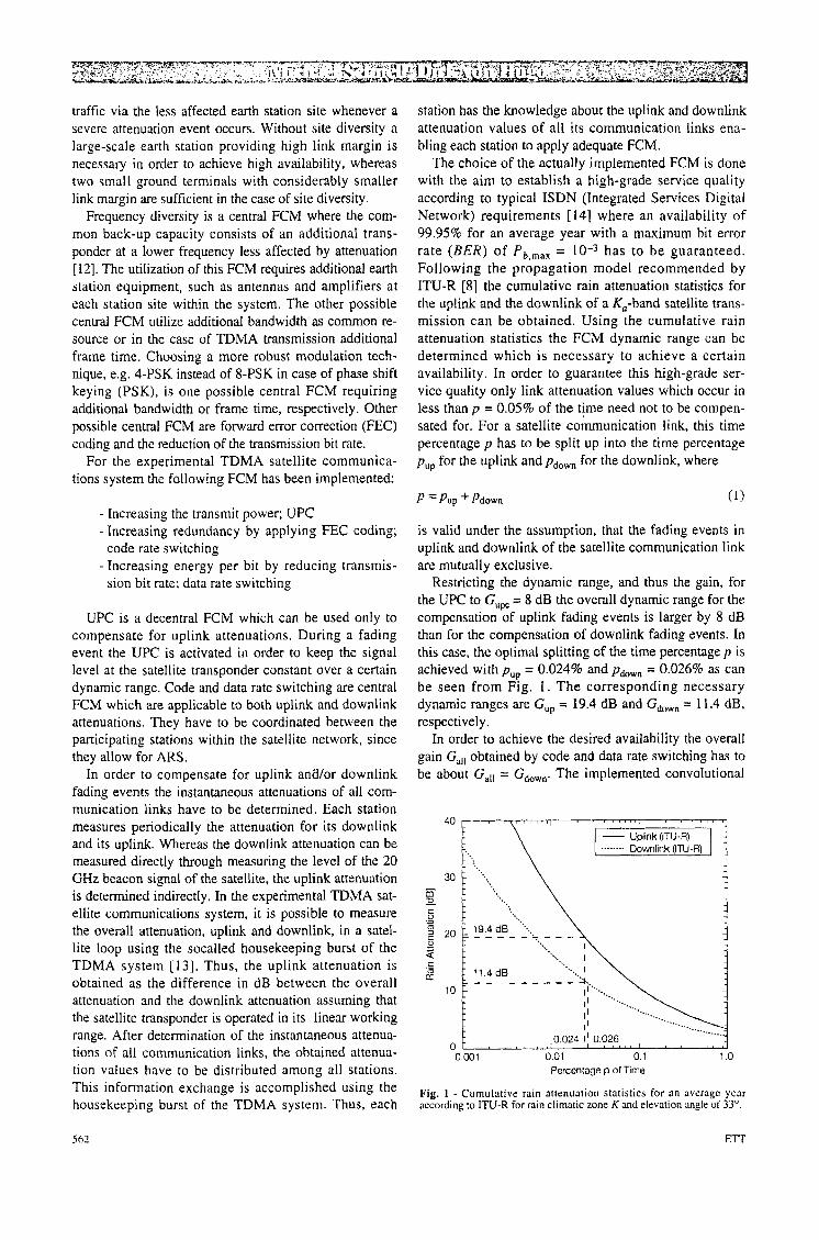
The choice of the actually implemented FCM is done with the aim to establish a high-grade service quality according to typical ISDN (Integrated Services Digital Network) requirements [ 141 where an availability of 99.95% for an average year with a maximum bit error rate ( B E R ) of Pb,max = has to be guaranteed. Following the propagation model recommended by ITU-R [8] the cumulative rain attenuation statistics for the uplink and the downlink of a Ka-band satellite trans- mission can be obtained. Using the cumulative rain attenuation statistics the FCM dynamic range can be determined which is necessary to achieve a certain availability. In order to guarantee this high-grade ser- vice quality only link attenuation values which occur in less than p = 0.05% of the time need not to be cornpen- sated for. For a satellite cokun ica t ion link, this time percentage p has to be split up into the time percentage pup for the uplink andpPdown for the downlink, where
is valid under the assumption, that the fading events in uplink and downlink of the satellite communication link are mutually exclusive.
Restricting the dynamic range, and thus the gain, for the UPC to G,, = 8 dB the overall dynamic range for the compensation of uplink fading events is larger by 8 dB than for the compensation of downlink fading events. In this case., the optimal splitting of the time percentage p is achieved with p = 0.024% and pdown = 0.026% as can be seen from Fig. 1. The corresponding necessary dynamic ranges are G,, = 19.4 dB and Gdown = 11.4 dB, respectively.
In order to achieve the desired availability the overall gain G,,, obtained by code and data rate switching has to be about Gal, = Gdown. The implemented convolutional
0.001 0.01 0.1 1 .o Percentage p of Time
Fig. 1 - Cumulative rain attenuation statistics for an average year according to ITU-R for rain climatic zone K and elevation angle of 33".
562 Err
’:; . . .
~-
Table 1 - Implemented FCM for uplink and downlink
Code Rate Switching 8.5 dB
Data Rate Switching 3.0 dB
Doubled Frame Time
Doubled Frame Time
i UPC I 8.0 dB I Transmit Power i
Total 19.5 d 8 Transmit Power + Fourfold Frame Time
___ Code Rate Switching 8.5 dB
I Data Rate Switching I 3.0 dB I Doubled Frame Time I
.-
Doubled Frame Time
~ Total I 11.5 dB I . Foudold Frame Time I
Attenuation
c 2.0dB
> 2.0dB
> 5.0dB
> 6.5 dB
> 8.0dB
___-
code [ 13, 151 allows for different code rates r = 415, 213, 112 using puncturing techniques [ 161. The resulting theo- retical coding gains at a BER of P, = 10-6 are 4.2, 6.7, and 8.5 dB, respectively. Thus, the maximum achievable coding gain is 8.5 dB. The possible data rate reduction factors K supported by the experimental TDMA system are K = 2,4,8 and the corresponding theoretical gains are 3, 6, 9 dB. As can be seen, code rate switching is much more efficient than data rate switching i n terms of achievable gain versus time expansion. Data rate switch- ing can be restricted to a factor K = 2 avoiding large time expansion, since a maximum data rate switching gain of 3 dB is sufficient to achieve the required overall gain of Gall = 11.4 dB. In Table 1 the implemented FCM for both the uplink and the downlink are summarized. Besides the corresponding theoretical gains the costs to be paid for the different FCM are reported.
The UPC is realized by a closed loop control algo- rithm. The transmission power is increased until the received signal level at the satellite approaches the specified nominal value. The received signal level can be calculated using the measured uplink attenuation. In order to obtain reliable attenuation data all short-time signal oscillations caused by noise and tropospheric scintillations have to be removed by a corresponding smoothing procedure. Online smoothing of the meas- ured data is performed applying a first-order low-pass filter with 3 dB cut-off frequency&, = 0.2 Hz.
Code and data rate switching are implemented apply- ing a table look-up control algorithm. Since code rate switching is much more efficient than data rate switching, code rate switching is applied before data rate switching. The corresponding look-up table is shown in Table 2, where an additional system margin Msys = 2 dB is consid- ered. Note, the chosen switching threshold do not fully exploit the theoretical gains of code and data rate switch- ing. Due to implementation losses the swichting threshold are chosen slightly lower than indicated by the theoretical
Code Rate Data Rate Gain Switching Switching
( r ) (R,) EJNO
111 4.0 MBaud 0.0 dB
415 4.0 MBaud 3.0 dB
213 4.0 MBaud 4.5 dB
1 I2 4.0 MBaud 6.0 dB
1 12 2.0 MBaud 9.0 dB
gains. The switching thresholds refer to the “remaining attenuation”, i.e. the attenuation of a satellite link which is present after substraction of the gain obtained by UPC. If the remaining attenuation exceeds a threshold switching is done immediately. Switching back, however, is retard- ed employing a hysteresis of 1 dB.
Table 2 - Look-up table for code and data rate switching
3. MEASUREMENT CAMPAIGN AND RESULTS
The experimental TDMA satellite network consists of four k,-band terminals located at four sites in Germany and Switzerland within three different rain cli- matic regions following ITU-R [17]. The locations are at the Deutsche Telekom AG at Berlin (ITU-R rain cli- matic zone E ) , the Technology Center of Deutsche Telekom AG at Darmstadt (zone H), the Institute for Communications Technology at the German Aerospace Center (DLR) at Oberpfaffenhofen near Munich (zone K ) , and the Swiss Telecom at Bern (zone K ) . Although originally a transmission via K,,-band payload of OLYMPUS had been foreseen due to satellite unavail-
Vol. 9. No. 6 November- December I Y Y Y 563
10.0
~ 8.0 - 5.0
d 4.0 .-
2 2.0
0.0 L? g -2.0
7 -6.0
$ -8.0
- 5 -4.0 1
-1 0.0
-1 2.0
;? t Lost Data Bursts 2 2) 1000 Zk! 3
Downlink Attenuation
~ 1 0 0 0 0 : I I I I ' I I 1 1 I ' I " 1 ' " ' i? Number of Bit Errors m + Lost Data Bursts - m 1000 3 2
9.58 9.60 9.62 9.64 9.56 9.68 9.70 9.72 Time (UTC) F]
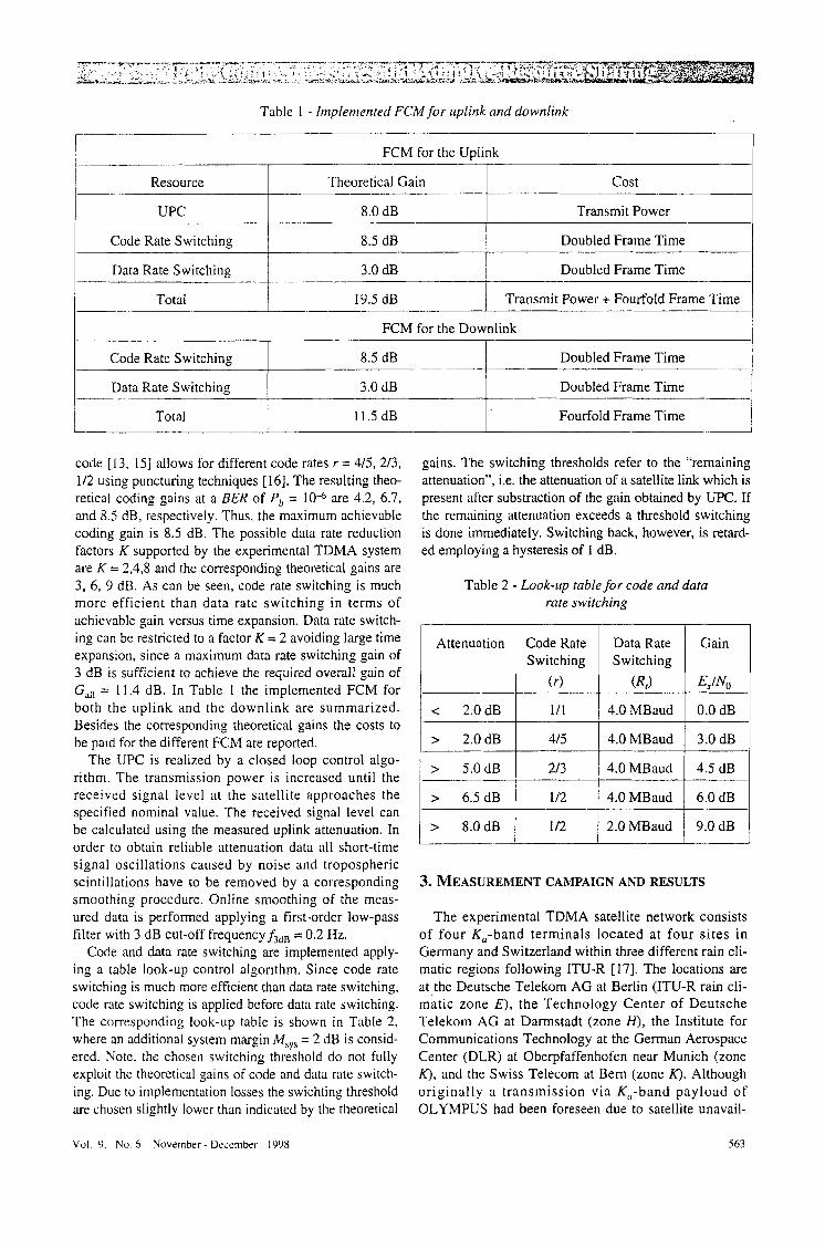
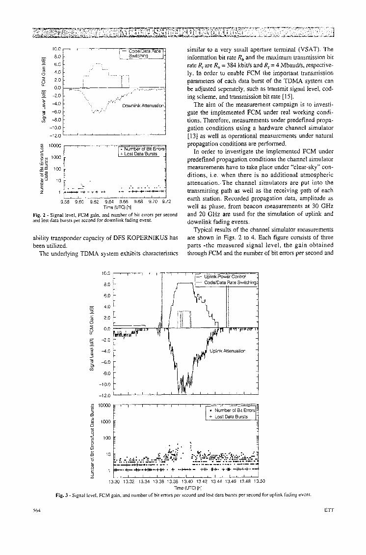
Fig. 2 - Signal level, FCM gain, and number of bit errors per second and lost data bursts per second for downlink fading event.
ability transponder capacity of DFS KOPERNIKUS has been utilized.
The underlying TDMA system exhibits characteristics
similar to a very small aperture terminal (VSAT). The information bit rate R, and the maximum transmission bit rate R, are R, = 384 kbit/s and R, = 4 Mbaud/s, respective- ly. In order to enable FCM the important transmission parameters of each data burst of the TDMA system can be adjusted seperately, such as transmit signal level, cod- ing scheme, and transmission bit rate [15].
The aim of the measurement campaign is to investi- gate the implemented FCM under real working condi- tions. Therefore, measurements under predefined propa- gation conditions using a hardware channel simulator [ 131 as well as operational measurements under natural propagation conditions are performed.
In order to investigate the implemented FCM under predefined propagation conditions the channel simulator measurements have to take place under "clear-sky'' con- ditions, i.e. when there is no additional atmospheric attenuation. The channel siinulators are put into the transmitting path as well as the receiving path of each earth station. Recorded propagation data, amplitude as well as phase, from beacon measurements at 30 GHz and 20 GHz are used for the simulation of uplink and downlink fading events.
Typical results of the channel simulator measurements are shown in Figs. 2 to 4. Each figure consists of three parts -the measured signal level, the gain obtained through FCM and the number of bit errors per second and
10.0
8.0
6.0
.c 2.0 8 5 0.0 lL
3 -2.0 U - -
-4.0 - 3 - 2 -6.0 - m 5
-8.0
-10.0
- -
-12.0
c
4
--++-*-+I+. c *- **it. +1+4+t+-k.- l ~ l ~ l ~ i ~ l c l ~ l t l ~ ~ ~
13.30 13.32 13.34 13 36 1338 13.40 13.42 13.44 13.46 13.48 13.50 Time (UTC) [hI
Fig. 3 - Signal level, FCM gain. and number of bit errors per second and lost data bursts per second for uplink fading event
lost data bursts per second. Fig. 2 shows the results for a downlink fading event, whereas in Fig, 3 the results for an uplink fading event are given. The results for simulta- neously occuring fading events at the transmitting and receiving earth station are shown in Fig. 4.
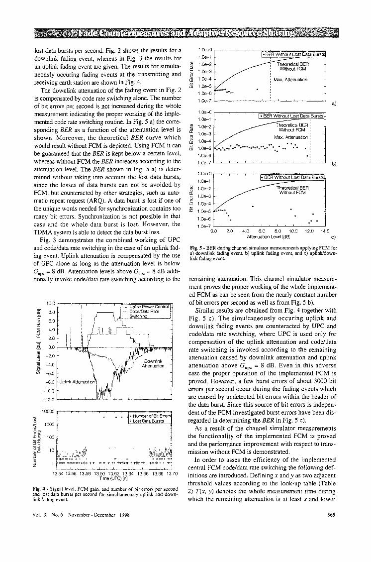
The downlink attenuation of the fading event in Fig. 2 is compensated by code rate switching alone. The number of bit errors per second is not increased during the whole measurement indicating the proper working of the imple- .merited code rate switching routine. In Fig. 5 a) the corre- sponding BER as a function of the attenuation level is shown. Moreover, the theoretical BER curve which would result without FCM is depicted. Using FCM it can be guaranteed that the BER is kept below a certain level, whereas without FCM the BER increases according to the attenuation level. The BER shown in Fig. 5 a) is deter- mined without taking into account the lost data bursts, since the losses of data bursts can not be avoided by FCM, but counteracted by other strategies, such as auto- matic repeat request (ARQ). A data burst is lost if one of the unique words needed for synchronization contains too many bit errors. Synchronization is not possible in that case and the whole data burst is lost. However, the TDMA system is able to detect the data burst loss.
Fig. 3 demonstrates the combined working of UPC and code/data rate switching in the case of an uplink fad- ing event. Uplink attenuation is compensated by the use of UPC alone as long as the attenuation level is below G,, = 8 dB. Attenuation levels above G,, = 8 dB addi- tionally invoke code/data rate switching according to the
I ' - Uplink Power Control - - m 8.0 - -. Code/Oata Rate 9 Switching
4.0
2.0 Y E 0.0
: -2.0 y 4 . 0
8 -6.0
- - _1
0
4 . 0
-10.0 ' -12.0 ' ' ' '
1 0 0 0 0 ~ , I , I , I ~ , , 9 . . . - Number of Bit Errors
3 t Lost Data Bursts E c
5 1 yI-ci-+-tt++ t+++-*+*i+ +-+.. i- 1 , , , , / , , , , 1 , / I
13.54 13.56 13.58 13.60 13.62 13.64 13.66 13.68 13.70 Time (UTC) [h]
Fig. 4 - Signal level. FCM gain, and number of bit errors per second and lost data bursts per second for simultaneously uplink and down- link fading event.
1 .Oe+O 1.oe-1
0 1.oe-2 a: 1 .Oe-3
. I % 1.Oe-5
1 .Oe+O 1 .oe-1
g 1.oe-2 1.0e3
& 1.Oe-4 % 1.Oe-5
Max. Attenuation :
.. 1 .oe-6 * : 1.Oe-7 ' I " " " " ' I
EER Without Lost Data Burst
, Theoretical BER Without FCM
1 .Oe+O
1 .Oel 'u 1.oe-2 2 L 1.0e-3 e z 1.Oe-4
hout Lost Data Burst
2 L 1.0e-3 e z 1.Oe-4
1.Oe-6 *. 2- -1 ."" I
0.0 2.0 4.0 6.0 8.0 10.0 12.0 14.0 Attenuation Level [dE] C)
Fig. 5 - BER during channel simulator measurements applying FCM for a) downlink fading event, b) uplink fading event, and c) uplidddown- link fading event.
remaining attenuation. This channel simulator measure- ment proves the proper working of the whole implement- ed FCM as can be seen from the nearly constant number of bit errors per second as well as from Fig. 5 b).
Similar results are obtained from Fig. 4 together with Fig. 5 c). The simultaneously occuring uplink and downlink fading events are counteracted by UPC and code/data rate switching, where UPC is used only for compensation of the uplink attenuation and code/data rate switching is invoked according to the remaining attenuation caused by downlink attenuation and uplink attenuation above GUq. = 8 dB. Even in this adverse case the proper operation of the implemented FCM is proved. However, a few burst errors of about 3000 bit errors per second occur during the fading events which are caused by undetected bit errors within the header of the data burst. Since this source of bit errors is indepen- dent of the FCM investigated burst errors have been dis- regarded in determining the BER in Fig. 5 c).
As a result of the channel simulator measurements the functionality of the implemented FCM is proved and the performance improvement with respect to trans- mission without FCM is demonstrated.
In order to asses the efficiency of the implemented centraf FCM codefdata rate switching the following def- initions are introduced. Defining x and y as two adjacent threshold values according to the look-up table (Table 7) T(x, y ) denotes the whole measurement time during which the remaining attenuation is at least x and lower
Vol. 9, No. 6 November - December I998 565
-- ?.I-
,%
Max. Remaining Att.
T (0.0,2.0) [s]
R (0.0. 2.0) [%]
w (0.0, 2.0) [%I
than y . The FCM reliability R (x, y) is defined as
7.0 dB 3.75 dB 6.5 dB
183 956 392
94.5 98.3 90.3
5.5 1.7 9.7
where T, (x, y ) is that fraction of T (x, y ) where FCM are performed according to the remaining attenuation. Denoting T, (x, y ) as that fraction of T (x, y ) where more powerful FCM are performed than necessary the waste of FCM resources W (x, y ) is given by
F (0.0, 2.0) [%]
T (2.0,5.0) [s]
R (2.0, 5.0) [%]
Finally, the FCM failure F (x, y ) is defined as
0.0 0.0 0.0
55 27 138
78.2 88.9 71.7
(3)
W (2.0, 5.0) [%]
F (2.0, 5.0) [%]
T (5.0,6.5) [s] _.
(4)
-~ 14.5 0.0 26.1
7.3 11.1 2.2
33 37
___-
where 7) (x, y ) is that fraction of T (x, y ) where less pow- erful FCM are performed than necessary. Evidently, eqs. ( 2 ) to (4) fulfil the relation
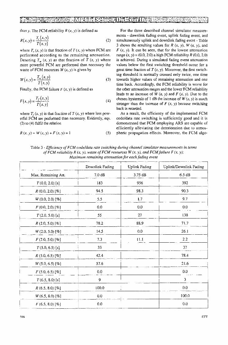
For the three described channel simulator measure- ments - downlink fading event, uplink fading event, and simultaneously uplink and downlink fading event - Table 3 shows the resulting values for R (x, y ) , W (x, y). and F (x, y ) . It can be seen, that for the lowest attenuation range (x. y ) = (0.0,2.0) a high FCM reliability R (0.0,2.0) is achieved. During a simulated fading event attenuation values below the first switching threshold occur for a great time fraction of T (x, y). Moreover, the first switch- ing threshold is normally crossed only twice, one time towards higher values of remaining attenuation and one time back. Accordingly, the FCM reliability is worse for the other attenuation ranges and the lower FCM reliability leads to an increase of W (x, y ) and F (x, y) . Due to the chosen hysteresis of 1 dB the increase of W (x, y ) is much stronger than the increase of F (x, y ) because switching back is retarded.
As a result, the efficiency of the implemented FCM code/data rate switching is sufficiently good and it is demonstrated that FCM employing ARS are capable of efficiently alleviating the deterioration due to atmos- pheric propagation effects. Moreover, the FCM algo-
Table 3 - Efficiency of FCM code/data rate switching during channel simulator measurements in terms of FCM reliability R (x, y), wasfe of FCM resources W (x, y) , and FCM failure F (x, y);
Maximum remaining attenuation for each fading event
I 1 Downlink Fading I Uplink Fading I UplinkDownlink Fading I
42.4 78.4 I I I I R (5.0,6.5) [%]
~~
R (6.5, 8.0) [%I 100.0 0.0
W (6.5, 8.0) [%] 0.0 100.0
F (6.5. 8.0) [%] 0.0 0.0 .-
566 E r r
l'oe+o 1 .Owl
' ' ' ' ' ' [ BER Without Lost Data Bursts
1.Oe-5 f .Ow6
i Without FCM
- . ....... 2. ***f ............. ......... * . . .........
R (0.0, 2.0) [%]
w (0.0.2.0) [%I F (0.0, 2.0) [%I T (2.0, 5.0) [s]
rithms may be further improved for later commercial applications leading to an even higher efficiency.
76.0
24.0
0.0
8365
Table 4 - Efficiency of FCM code/data rate switching during operational measurements in terms of FCM
reliability R (x, y ) , waste of FCM resources W (x, y), and FCM failure F (x, y ) ; Maximum remaining
attenuation for all fading events
Operational Measurements
Max. Remaining Att. 12.25 dB
T (0.0,2.0) [s]
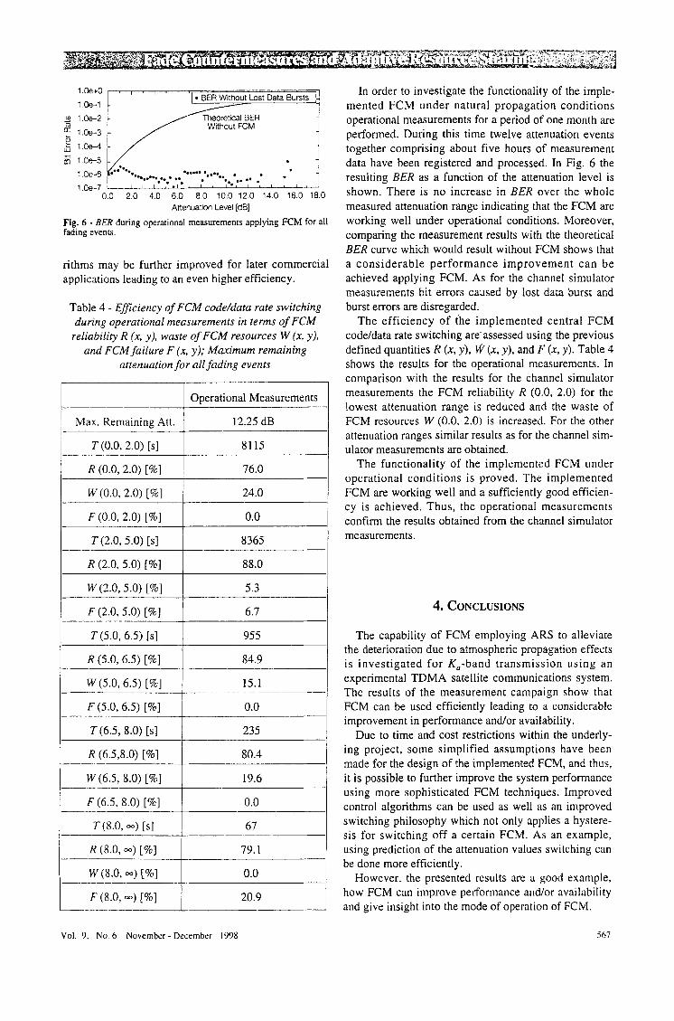
In order to investigate the functionality of the imple- mented FCM under natural propagation conditions operational measurements for a period of one month are performed. During this time twelve attenuation events together comprising about five hours of measurement data have been registered and processed. In Fig. 6 the resulting BER as a function of the attenuation level is shown. There is no increase in BER over the whole measured attenuation range indicating that the FCM are working well under operational conditions. Moreover, comparing the measurement results with the theoretical BER curve which would result without FCM shows that a considerable performance improvement can be achieved applying FCM. As for the channel simulator measurements bit errors caused by lost data burst and burst errors are disregarded.
The efficiency of the implemented central FCM codeldata rate switching are-assessed using the previous defined quantities R (x , y ) , (x, y), and F (x. y ) . Table 4 shows the results for the operational measurements. In comparison with the results for the channel simulator measurements the FCM reliability R (0.0, 2.0) for the lowest attenuation range is reduced and the waste of FCM resources W (0.0, 2.0) is increased. For the other attenuation ranges similar results as for the channel sim- ulator measurements are obtained.
The functionality of the implemented FCM under operational conditions is proved. The implemented FCM are working well and a sufficiently good efficien- cy is achieved. Thus, the operational measurements confirm the results obtained from the channel simulator measurements.
R (2.0, 5.0) [%]
W (2.0, 5.0) [%]
F (2.0, 5.0) [%] 4. CONCLUSIONS
T (5.0, 6.5) [s] 955 I R (5.0.6.5) [%]
W (5.0, 6.5) [%I
F (5.0.6.5) [%I T(6 .5 , 8.0) [s] 1 235 I R (6.5.8.0) [%I 1 80.4 I W (6.5, 8.0) [%I F (6.5, 8.0) [%]
R (8.0, -) [%I w (8.0, =) [%I
F (8.0, -) [%] 20.9
The capability of FCM employing ARS to alleviate the deterioration due to atmospheric propagation effects is investigated for K,-band transmission using an experimental TDMA satellite communications system. The results of the measurement campaign show that FCM can be used efficiently leading to a considerable improvement in performance and/or availability.
Due to time and cost restrictions within the underly- ing project, some simplified assumptions have been made for the design of the implemented FCM, and thus, it is possible to further improve the system performance using more sophisticated FCM techniques. Improved control algorithms can be used as well as an improved switching philosophy which not only applies a hystere- sis for switching off a certain FCM. As an example, using prediction of the attenuation values switching can be done more efficiently.
However, the presented results are a good example, how FCM can improve performance and/or availability and give insight into the mode of operation of FCM.
Vol. 9, No. 6 November - December 1998 Sh7
Acknowledgement
The authors would like to thank all researchers from the Swiss Telecom, the Deutsche Telekom AG, the RWTH Aachen, and the DLR who have contributed to the successful operation of the experimental TDMA sat- ellite communications system.
Manuscript received on November 12, 1996.
REFERENCES
[ I ] F. Carassa: Adaptive methods to counteract rain attenuation effects in the 20/30 GHz band. “Space Communications and Broadcasting”, Vol. 2, 1984, p. 253-269.
[2] F. Dintelmann, G. Ortgies, F. Riicker, R. Jakoby: Results from 12- to 30 Glfz German propagation experiment carried out with radiometers and the olympus satellite. “Proceedings o f the
[3] M. Lugert et al.: The 20130 GHr cooperative TDMA-experi- ments. Proceedings of the 2-nd Olympus Utilization Conference, Sevilla. April 1993.
[4] L. Dossi. E. Matricciani. M. Mauri: Robust control system for rerource-shared satellite communication networks affected by rain attenuation: experimental perfonnancr ut 20/30 CH:. “Aka Frequenza-Rivista di Eletuonica”, Vol. 6, 1994, p. 121-124.
[ 5 ] F. Davarian: K,-band propagation research using ACTS. “International Journal on Satellite Communications”, Vol. 14,
[6] R. Bauer: KO-band propagation measurements: an opportunity with the advanced Communications technology satellite (ACTS). “Proceedings o f the IEEE, Vol. 85, No. 6, 1997, p. 853 - 862
[7] N. Fugono. K. Yoshimura, R. Hayashi: Japans millimeter wave
IEEE”, VOI. 81, 1993, p. 876-884.
1996. p. 267 - 282.
satellite communication program. “IEEE Transactions on Communications”, Vol. COM-27, 1979, p. 1381-1391.
[8] ITU-R Recommendation 61 8-2: Propagation data and predic- tion methods required for the design of earth-space telecommu- nications systems. “ITU-R RPN Series Recommendations, Propagation in Non-Ionized Media”, Geneva 1992.
[9] J. Horle: Uplink power control of satellite earth-stations as a fade-countermeasure of 20/30 GHz communicarion svstems. *“International Journal on Satellite Communications”, ’Vol. 6, 1988, p. 323 - 330.
[lo] D. B. Hodge: An improved model for diversity gain on earth- space propagation paths. “Radio Science”, Vol. 17, 1982, p.
[ I l l Y. Suzuki. M. Shimada, H. Mineno, T. Shozuka, H. Kuroiwa, H. Inomata: TDMA site diversity switching experiments with Iapanese CS. “IEEE Journal on Selected Areas in Communications”, Vol.
[ 121 F. Carassa, E. Matricciani. G. Tartara: Frequency diversity and its apphcations. “International Journal on Satellite Communications”.
[I31 D. von Hugo, A. Wilde: An adaptive resource sharing strategy for TDMA, “International Joumal o f Satellite Communications”,
[I41 ITU-R Rec. 614-1: Allowable error performance for a hypio- thetical reference digital path in the fixed-satellite service .... “ITU-R RPN Series Recommendations, Propagation in Non- Ionized Media’’, Geneva 1992.
1151 D. Kreuer, A. Radermacher. S. Martin, Th. Frach: A protofype adaptive fade countermeasure system for TDMA operation at K, band. Proceedings of the Personal, Indoor, and Mobile Radio Conference (PIMRC.94). September 1994, The Hague, The Netherlands.
[ 161 J. Hagenauer: Rate compatible punctured convolutional codes (RCP C-Codes) and their application. “IEEE Transactions on Communications”, Vol. 36, 1988. p. 389-400.
[ 171 ITU-R Recommendation 837: Characteristics of precipitation for propagation modeling. “ITU-R RPN Series Recommendations, Propagation in Non-Ionized Media”, Geneva 1992.
1393 - 1399.
SAC-1.1983, p. 674 - 680.
Vol. 6, 1988, p. 313-322.
Vol. 12, 1994, p. 249-256.
568