Embed Size (px)
Citation preview

Lessons Learned From Generator Destructive Testing
Calvin Howard, Beth Andrews, and Douglas Taylor Avista Utilities
Normann Fischer, Dale Finney, and Matchyaraju Alla Schweitzer Engineering Laboratories, Inc.
Presented at the 74th Annual Georgia Tech Protective Relaying Conference
Virtual Format April 28–30, 2021
Previously presented at the 74th Annual Conference for Protective Relay Engineers, March 2021,
and 12th Australian Protection Symposium, November 2020
Previous revised editions released April 2020 and October 2019
Originally presented at the 46th Annual Western Protective Relay Conference, October 2019

1
Lessons Learned From Generator Destructive Testing Calvin Howard, Beth Andrews, and Douglas Taylor, Avista Utilities
Normann Fischer, Dale Finney, and Matchyaraju Alla, Schweitzer Engineering Laboratories, Inc.
Abstract—Avista Utilities, an energy company primarily servicing eastern Washington and northern Idaho, has been in the process of upgrading a set of 8.8 MVA, 4 kV, 48-pole, 60 Hz generators at one of their hydroelectric facilities on the Spokane River. The authors took this unique opportunity to perform destructive testing on one of these generators prior to its scheduled upgrade. The testing was performed during the fall of 2018. This paper describes the planning and execution components of this destructive testing and also discusses the lessons learned throughout the entire process.
In this paper we discuss the layout of the power station and the generator, as well as the constraints they placed on the tests that could be performed. We describe the fault survey we performed on the machine and the resulting fault locations the survey identified for testing. We describe the process used to estimate the fault currents, the test setup and fixtures that were implemented, and the safety precautions established for the various tests. We provide an overview of the test results, including the generator terminal voltages and currents, the branch currents of the faulted phases, and the field voltage and current at the time of the fault. Lastly, in the paper we discuss future uses of the fault data, such as protection function development and verification and generator computer model validation. This paper is the first in a series of papers that will discuss the destructive testing of this generator and what we learned.
I. INTRODUCTION This paper describes the destructive testing (also known as
staged-fault testing) carried out on a hydro generator prior to rewind and provides analysis of the test results.
Synchronous generators form the backbone of the electric power system. When a fault occurs within a generator, it not only impacts the generator, but could also jeopardize the stability of the power system. Therefore, it is essential that faults in a generator be detected and isolated as rapidly as possible.
To effectively protect a generator, a thorough understanding of the different failure modes and their impact on the generator is required.
In its simplest form, a synchronous generator consists of a set of windings wound onto a rotor onto which a dc voltage is impressed. This creates a stationary magnetic field. The prime mover spins the rotor at a synchronous speed to create a rotating magnetic field. This rotating magnetic field induces ac voltage on a set of stationary windings known as the stator windings. A winding failure in either the rotor or the stator will impact the performance of the synchronous generator and its ability to deliver power to the power system.
Winding failures (both stator and rotor) are responsible for most generator outages. One study reported that stator winding failures alone account for approximately 40 percent of generator outages [1].
Before deciding on the type and location of faults to apply during the testing, we examined the mechanisms that can lead to a winding failure. Winding failure (both in the stator and in the rotor) occurs mainly as a result of insulation failure. In this paper, we will briefly discuss how insulation failure occurs, but a more detailed description can be found in [2] and [3].
Some of the insulation failure mechanisms are as follows: • Thermal deterioration. This is one of the most
common forms of winding failure, especially in air- or hydrogen-cooled generators. Thermal deterioration is essentially an oxidation reaction that occurs when the temperature is high enough to cause the chemical bonds in the organic parts of the insulation to break because of induced thermal vibrations. The main cause of thermal deterioration is operating the generator at too high of a temperature.
• Loose stator coils. This is one of the most common failures in large gas and steam turbine generators [3]. As the MVA of the machine increases, the forces acting on the winding bars or coils increase with the square of the current. If the coils are securely held in the slot, these forces have little impact. However, if the coils are not held securely in the slot, as the current increases, the coils begin to vibrate radially more vigorously in the slot. Loose coils can develop because of insulation shrinkage or thermal cycling [4]. The serrated edge of the core laminations makes an effective abrasive surface, and the increase in coil vibration abrades away the coil insulation. Prolonged exposure to an external fault can also result in loose coils in the stator.
• Wearing or cracking of insulation. This can also occur in the end winding as a result of excessive vibration. The root cause can be poor bracing or high transient torque events such as close-in faults or out-of-phase synchronizing.
• Repetitive voltage surges. These can induce gradual deterioration of the turn or groundwall and phase insulation. Lightning or switching surges have very short rise times (high frequency), so the surge voltage is not evenly distributed across the winding. At this high frequency, the winding’s series inductive impedance is much larger than the shunt capacitive impedance to ground. As much as 40 percent of the voltage surge can appear across the first turn [3]. A high interturn voltage can give rise to a partial discharge if there is an air pocket near the copper

2
conductor, which will degrade the conductor insulation. If enough surges occur and the insulation has sufficiently degraded, a turn-to-ground or turn-to-turn fault will result.
• Electrical tracking. This is caused by winding contamination that enables current to flow over the surface of the insulation, especially in the end windings. These currents degrade the groundwall insulation and eventually cause it to fail, leading to a turn-to-ground fault. Contaminants such as oil, dust, and water can also weaken the insulation mechanically.
From these failure mechanisms, we conclude that when the turn insulation fails, the generator will experience one of the following types of faults:
• Turn-to-ground (phase-to-ground) faults occur if both the turn and groundwall insulation fails. The location of the insulation failure and the grounding of the generator determine the magnitude of the fault current. In general, in high-impedance grounded generators (generators connected to the power systems via a generator step-up [GSU] transformer), the ground fault current is limited to less than 15 A for a ground fault close to the terminals of the generator. It should be noted, however, that a ground fault often begins as an intermittent fault [5]. In this case, the capacitive discharge currents increase the damage potential. A ground fault closer to the neutral terminal of the generator will result in a lower fault current.
• Turn-to-turn faults occur if the turn insulation between two or more adjacent turns of the same branch fails. The magnitude of the fault current in the shorted turn is several times the full-load current of the generator. For example, assume that a generator has a nominal voltage of 13.8 kVLL (7.967 kVLN) and that each winding consists of 200 turns where each turn has an impedance of approximately 3 mΩ. A turn-to-turn fault involving a single turn will result in a fault current of approximately 13 kA flowing in that turn.
• Branch-to-branch faults occur in generators that have multiple parallel branches per phase, as is the case for the Little Falls generator discussed later in this paper (see Section III). Faults between branches can occur at the end windings or if the branches share the same slot. These faults result in high fault currents that are not detected by the generator differential protection element.
• Phase-to-phase faults occur if the turn insulation between two adjacent turns of two different phases fails. This can occur in the end winding. It is also possible to have a turn-to-ground fault on two different phases. Essentially, this is a phase-to-phase fault and results in a large fault current.
Although not commonly employed, a fault survey examines the layout of the winding to identify possible locations where failures can occur. This can help determine the possible fault
types and the required types of protection. Ideally, by determining the fault currents and voltages at the potential fault points, the worst-case operating quantities can be determined [6].
The paper is laid out as follows: • Section II addresses the reasons staged-fault testing is
beneficial to the industry. • Section III covers the requirements to do staged-fault
testing, from the constraints the utility imposed onto the test team, to the selection of the correct fault switch, to the selection of the fault points and the correct placement of instrumentation transformers to capture the required fault data. Equally important are the safety requirements during such testing.
• Section IV covers the results obtained during the staged-fault testing, observations we made during the testing, and the lessons learned.
• Section V describes the conclusions we drew from the staged-fault testing.
II. IMPORTANCE OF STAGED-FAULT TESTING Most generator faults can be attributed to winding insulation
failures. However, there are very few complete event recordings available for these faults. Therefore, studying these types of failures and developing the appropriate protection algorithms to detect them is challenging. Rotor and stator turn-to-turn faults were of interest to the authors because they wanted data to validate protection algorithms specifically designed for the detection of turn-to-turn faults in generators [7] [8].
Until a few years ago, electromagnetic transient program (EMTP) generator and transformer models were not developed for internal fault applications. When EMTP developers for generator and transformer models developed models that allowed the application of internal faults, protection engineers began studying these types of faults in more detail. These models presently have limitations with respect to the location and type of faults that can be applied. The fidelity of some models is problematic. For example, a certain model may not accurately reproduce the third harmonic, upon which some generator protection principals are built. Furthermore, the model may not have been validated against actual field cases because of the lack of actual field data. So, how can these models be validated?
Staged-fault testing allows the application of faults in a controlled manner and environment. Furthermore, it allows for the capture of all relevant data. The data produced during these tests can be used not only to study the behavior of a generator during such fault conditions but can also be used to verify and improve the EMTP models.
III. REQUIREMENTS FOR STAGED-FAULT TESTING In a staged-fault test, the goal is to create a controlled fault
on a generator to capture the resulting currents and voltages. The equipment used to create the fault is exposed to primary

3
currents and voltages. This section introduces the layout of the Little Falls generating station in Washington State, where the destructive testing was performed, and discusses the constraints the station placed on testing. Following the discussion of the station layout and constraints, this section focuses on four main points:
• Where on the stator windings the fault points should be located.
• The fault current carrying and breaking capacity of the fault switch.
• How the generator should be instrumented to measure all the relevant data.
• Safety requirements for the testing.
A. Station Layout and Constraints The generation station consists of four hydro generation
units connected to the power system through two GSU transformers, as shown in Fig. 1. Unit 4 was the final generator in the station scheduled for an upgrade and was the unit that testing was performed on. Unit 3 had recently been upgraded. Avista did not want to risk damaging the unit; therefore, no tests were performed while Unit 3 was online.
Fig. 1. Simplified one-line diagram of Little Falls generation station.
The generator upgrade consisted of a complete replacement of the generator stator and turbine to provide increased capacity; therefore, any modifications to the stator windings as part of the testing were permissible. However, the generator rotor poles were going to be refurbished, so no permanent alterations to the field windings were allowed. The generator breaker was also not part of the upgrade, so faults placed on the generator had to have enough generator impedance between the fault point and the power system to limit the fault current to an acceptable level. For the tests, the maximum fault current that the generator breaker could break had to be below the maximum load current of the generator. Faults that would generate fault currents above the maximum load current of the generator had to be conducted with the generator offline.
All the protection for the unit was left in operation for the testing. These protective relays were all electromechanical relays not capable of recording fault data.
B. Fault Point Locations To determine where the fault (test) points on the stator
winding should be physically located, we needed the following three sets of drawings:
• The physical representation of the generator, as shown in Fig. 2.
• A winding configuration and terminal connection diagram of the generator, as shown in Fig. 3.
• The partial winding layout, winding span (coil pitch), coil configuration, and grouping for the Little Falls generator, as shown in Fig. 4.
Fig. 2. Physical representation of the generator at Little Falls, showing the four quadrants of the generator and the location of the winding neutral (N) and terminal (T) connections. Note that this is a horizontal hydro generator.
Fig. 3. Winding configuration and terminal connection diagram showing the location of fault points.

4
Fig. 4. Partial winding layout diagram for the Little Falls generator showing the coil pitch and coil groups.
Fig. 3 shows that each generator phase is composed of four windings (branches). Reflecting this back onto Fig. 2 demonstrates that the generator is divided into four quadrants. Each quadrant contains a set of three phase windings or branches. Fig. 4 shows that an individual phase winding branch is made up of 12 coil groups of 6 turns (i.e., 3 coils of 2 turns each per group), yielding a total of 72 turns per branch per phase. The location of each winding’s terminal and neutral connections is also shown in Fig. 4. With an examination of the physical layout of the machine (i.e., when we map Fig. 4 onto Fig. 2), we can perform a fault survey and thereby establish where and which types of faults are most likely. A few interesting observations are as follows:
• The terminal connection for one winding is almost adjacent to the neutral connection of another winding. In Fig. 4, the A-phase terminal connection of Branch 1 in slot 1 is two slots away from the B-phase neutral connection of Branch 4 in slot 4. The letters T and N in Fig. 1 illustrate the fact that the neutral connection from Branch 1 is adjacent to the terminal connection of Branch 4. Therefore, phase-to-phase faults in the end-winding are possible.
• Coils from the same phase but from a different branch share the same slot. Furthermore, these coils are from different locations on the winding (i.e., in some cases, one coil is located close to the neutral connection and the other coil is located close to the terminal connection). For example, in Fig. 4 slot 13, a coil that
connects to the terminal connection of Branch 1, B-phase shares the slot with a coil close to the neutral terminal of Branch 4 B-phase. From the survey, we identified 12 possibilities for this type of inter-branch fault.
• The notion that turn-to-turn faults can only occur between consecutive turns (e.g., between turns 1 and 2 or turns 2 and 3), as is the case in shunt reactors and transformers is not correct in multi-branch generators. For example, examining slot 10 in Fig. 4 shows that for the A-phase, Branch 1, Coil 2 (turn 3 and 4) share a slot with Branch 1, Coil 4 (turn 7 and 8). Therefore, it is possible to have a multiturn fault that shorts out more than one turn.
The accurate identification of fault points is critical. A fault connection that is off by one slot can place the fault at a completely different location in the winding or on a different phase, producing misleading results.
Furthermore, the fault points need to be located where they are easily accessible, and the distance between the fault points and fault switch must be a short as possible. A further point of consideration was that we wanted the fault points to be located closer to the neutral connection so that the potential difference to ground was low. Taking all these factors into consideration, all of the test points except for one are in Quadrant 1, and one test point is in Quadrant 4. The location of the test points is shown in Fig. 3, where the numbers following the hyphens indicate the number of winding turns the fault point is located at.

5
C. Fault Switch Carrying and Breaking Capacity To determine the carrying and breaking capacity for the fault
switch, we calculated the maximum fault current that would develop during the staged-fault testing. To calculate the maximum fault current, we used the following known generator electrical parameters:
Xd = 0.68 pu (steady-state direct axis reactance) Xd' = 0.161 pu (transient direct axis reactance) Xd'' = 0.161 pu (subtransient direct axis reactance)* Td' = 3.4 sec (transient time direct axis) Td'' = 0.0 sec (subtransient time direct axis)*
Xq = 0.5 pu (steady-state quadrature axis reactance) Xq' = 0.5 pu (transient quadrature axis reactance)** Xq'' = 0.161 pu (subtransient quadrature axis reactance) Tq' = 0.0 sec (transient time quadrature axis)** Tq'' = 0.03 sec (subtransient time quadrature axis)
* The Xd'' and Xd' are identical because Td'' = 0 sec. ** The Xq' and Xq are identical, because Tq' = 0 sec.
Fig. 3 shows that we need to calculate the fault current for the following fault types:
• Turn-to-turn faults (e.g., F1-to-F2 in Fig. 3) • Phase-to-phase faults (e.g., F2-to-F9) • Double phase-to-neutral faults (e.g., F2-to-F0 and
F8-to-F0) Using these data, we calculate the approximate maximum
symmetrical fault current that the fault switch will have to carry and break under the given fault conditions.
1) Turn-to-Turn Faults The fault current produced by a turn-to-turn fault is
proportional to the volts per turn and the number of turns involved, and inversely proportional to the impedance of the fault loop. For all practical purposes, the resistance of the stator winding is negligible when compared to the leakage inductance of the stator winding. We can calculate the self-inductance using (1). From the self-inductance, we can calculate self-reactance using the nominal frequency of the power system.
2 0 rself
AL n •
lµ µ
= (1)
where: n = number of turns μ0 = permeability of free space μr = relative permeability A = area in m2 l = length in m
All the parameters for (1) are obtainable except the value for μr for the generator stator core. Typical values of μr range from 2,000 to 80,000 for materials used in transformers and rotating machinery [9]. Furthermore, the self-inductance (Lself) is the
sum of the mutual inductance (LM) and the leakage impedance (LL), as shown in (2): self M LL L L= + (2)
However, only LL is important during a fault condition. Typically, LL is in the range of 0.06 to 0.1 pu of the total Lself for larger generators (5 MVA and higher). Therefore, by following this route, we would have had a wide range of values to choose from for the LL of the winding to calculate the fault current for a single turn-to-turn fault. Instead, we used the data we had. We knew the total steady-state self-reactance of the generator’s direct axis (Xd) was 0.68 pu. Each phase was comprised of four branches in parallel; therefore, Xd for one branch was equal to four times the Xd of the generator. Having obtained the Xd for one branch, we then calculated the value of total XLL for one branch by using the lower range value of 0.06 pu. Then, assuming a linear relationship between the total XLL and the number of turns, even though this was not strictly true, we calculated the fault current for a single turn-to-turn fault as shown in (3):
L _1wind d
per _ turnflt _1turn
L _ per _ turn
L X • 4 • 0.060.163 pu
VI
XL6.135 pu
=
=
=
=
(3)
To verify that our logic and thinking were correct and that our results were reasonable, we performed a similar analysis on a laboratory-sized generator—an 18 kVA, 6-pole machine at the University of Idaho. Our calculated values and measured values were within 10 percent of one another [10]. The generator is rated at 220 V, and the rated current is 46 A. The highest fault current we observed in this generator was 6.5 pu (≈300 A) for a fault involving 5 turns. The values are also consistent with the results of staged-fault tests carried out in the 1950s [11].
2) Phase-to-Phase Fault For a phase-to-phase fault at the terminals of the generator,
or if you have a phase-to-ground fault near the terminal connection of one phase and a second phase-to-ground fault near the terminal of a different phase, the symmetrical positive sequence current (I1) for these faults can be calculated as shown in (4):
11
1 2
1 2
fault 1 2
VI
Z Z
I I
I a • (a • I I )
=+
= −
= +
(4)
where: I2 = negative sequence current a = 1∠120° Z1 = positive sequence impedance Z2 = negative sequence impedance

6
For a phase-to-phase fault at the terminals of the generator we can make the substitutions shown in (5):
( )1 d ''
d '' q ''2
Z X
X XZ
2
=
+=
(5)
Substituting (5) into (4) results in (6):
11
d '' q ''d ''
VI
X XX
2
=+
+
(6)
Substituting the values of Xd'' and Xq'' into (6), we calculate the value of I1 and Ifault as follows:
fault
1I 3.125 pu
I 5.413 pu
=
= (7)
3) Double-Phase-to-Ground Fault (Same Phase) We can view a double-phase-to-ground fault as a single
turn-to-ground or single line-to-ground fault on the same phase, but not necessarily on the same branch, where the neutral grounding resistor is bypassed or short-circuited by the second turn-to-ground fault. These types of faults can occur in multi-branch generators, as described in the fault survey.
11
1 2 0
1 2 0
fault 1 2 0
VIZ Z Z
I I II I I I
=+ +
= == + +
(8)
where: I0 = zero sequence current
For a generator, we know that the value of the zero-sequence impedance (Z0) is much smaller than Z1 and is generally between 0.05 pu and 0.2 pu for a salient pole machine with damper winding [12]. To err on the conservative side, we used a value of Z0 = 0.05 pu. Using (4) for the Z1 and Z2 and (8), we calculated the symmetrical positive sequence and fault current.
fault
1I 2.703 pu
I 8.109 pu
=
= (9)
The rated current of the generator is 1,284 A (1 pu); therefore, the maximum symmetrical rms fault current that the fault switch will need to interrupt is 10.41 kA. To obtain accurate fault information, we selected a minimum fault of 100 ms (6 cycles at 60 Hz), neglecting the transition of the generator reactance from the sub-transient value to the transient value and ignoring the dc component current decay. The maximum asymmetrical rms current that the fault switch would have to break is 18.603 kA.
D. Correctly Instrumenting the Generator for Testing Instrumenting the generator is a critical task during testing
since it ensures that we capture all relevant data. A simple schematic of the generator and the locations of the instrument transformers and the recording points is shown in Fig. 5.
Fig. 5. Measuring points for the destructive testing of the Little Falls generator.
The generator was equipped with the following instrumentation, from which measurements could be obtained during the test. It was not possible to change these for the purposes of the test.
1. A set of three-phase CTs with a ratio of 1500/5 and a C400 rating located at the neutral side of the generator.
2. A set of three-phase 1500/5 CTs located at the terminals of the generator.
3. An open-delta PT located at the terminals of the generator with a ratio of 4800/120 V.
4. The neutral grounding transformer (NGT) is a 5 kVA distribution transformer with a turn ratio of 4160/240 for voltage measurement across the grounding resistor (2.4 Ω) of the generator.
To obtain better visibility during this test series, the following additional measuring points were added to the generator.
1. Field current measurement using the voltage drop across a shunt resistor (500 A/50 mVdc).
2. Field voltage measurement. 3. Fault current measurement via a built-in CT in the
fault switch with a CT ratio of 1000/5 and a C400 rating.
4. A voltage measurement across the contacts of the fault switch. This was included for many reasons, but the primary reason was for safety i.e., to verify that the fault switch was opened before the beginning of every test and that we connected to the correct fault point. For this, we used a PT with a ratio of 4160/120 V.
5. Current measurement of three of the four branch currents. The reason for only instrumenting three of the four branches is that we could not secure the fourth CT properly because it would have been located at the top of the generator and we could not run the secondary wiring to the measuring point easily. We decided to omit this CT since we had the phase current measurement from the CT at the neutral and we could calculate the current in the fourth branch from this and the other three branch CTs. For this task, we selected CTs with a ratio of 400/5 and a C50 rating.
The complete set of measurement and recording devices used during the testing is shown in the appendix.

7
E. Safety Consideration During Testing Since safety was of the utmost importance, Avista and the
authors began meeting more than a year in advance of the scheduled generator outage to define the testing itinerary and to strategize the safest method of executing the test plan. A secondary but also important requirement was to prevent damage to the plant equipment, including the generator under test. The following precautions were put into place to protect both personnel and the plant equipment during the generator testing:
• All personnel onsite wore approved personal protective equipment.
• All the generator relay protection was left in place and active during the generator testing.
• Unit 4, the generator chosen for the test, was located furthest from the control room and closest to the plant entrance. Someone stood guard on the outside of the entrance during testing to prevent anyone from entering the plant.
• A temporary, eight-foot wooden wall was erected between the generator and the pathway from the plant entrance to the control room.
• In case of a fire during the testing, select individuals remained on the generator floor to improve response times, including the recloser operator, the high-speed camera operator, and the individual responsible for issuing the fault initiation countdown.
• All the personnel on the generator floor, and their equipment, were positioned between Units 2 and 3 to provide a significant barrier between them and Unit 4.
• Fire extinguishers were placed near the personnel on the generator floor and with the guard at the plant entrance.
• To synchronize communication, the plant operator, the personnel at the measurement station, the plant entrance guard, and the individual issuing the countdown on the plant floor were all issued radios.
IV. SUMMARY OF THE TEST RESULTS The following section details the result from the destructive
generator tests and discusses observations and what we learned during this series of tests. The results are presented in the order that they were executed.
A. Rotor Turn-to-Turn Fault Because of restrictions placed on the test team by Avista
with regards to faults on the rotor field winding, only one rotor turn-to-turn fault could be executed. For this test, we shorted a complete rotor pole because this did not require any drilling or altering of the rotor pole. The pole was shorted while the generator was stationary with no excitation applied. For a 48-pole generator, this is approximately equivalent to 2 percent of the rotor field winding.
In general, rotor turn-to-turn faults that only involve a few turns are not catastrophic in nature and the generator can continue operation. However, these types of faults are not easily detectable using electrical measuring techniques. This test was carried out both when the generator was offline and online.
An interesting observation from this test is that the asymmetry in the air-gap flux introduced by the rotor turn-to-turn fault caused a disturbance in the split-phase currents, as can be seen in Fig. 6.
This was an unexpected and interesting result from this test. As a result, we recommend that when a split-phase protection element operates, the integrity of rotor windings be tested. If we examine Fig. 6, we observe that the asymmetry in the air-gap flux caused a disturbance in the branch currents every 100 ms. This can be easily explained because the generator rotates at 150 rpm (48-pole generator), or 2.5 revolutions per second. The generator stator winding is made up of four parallel branches; therefore, the shorted pole passes a branch every 100 ms. When the shorted pole enters a branch, it changes the flux density in that branch, and this gives rise to the change in the branch current.
Fig. 6. A-phase branch currents during a 2 percent rotor turn-to-turn fault on the generator.
A rotor turn-to-turn fault involving a few turns is not readily observable by monitoring the voltage terminals, the phase currents, or the field current, as can be seen by examining Fig. 7.
8
Fig. 7. Generator terminal voltages, phase currents, and field current during a rotor turn-to-turn fault on the generator.
B. Phase-to-Ground Faults Following the rotor turn fault, we began the stator tests with
the phase-to-ground fault test series for several reasons, one of which was that this series of tests would produce the lowest fault current (less than 15 A). This would give the team time to work through any issues and gain confidence before engaging in the higher fault current tests. For this series of tests, the generator was online and exporting about 20 percent of rated power.
As mentioned in Section III, the generator was not instrumented with either wye-connected (star) PTs, nor was the generator instrumented with a broken-delta PT. Therefore, the only method available to identify a stator ground fault close to the generator neutral was to make use of the third harmonic undervoltage element. The results for a turn-to-ground fault one turn from the neutral of the generator (at 1.39 percent of the winding) are shown in Fig. 8.
The results for a turn-to-ground fault three turns from the neutral of the generator (at 4.16 percent of the winding) are shown in Fig. 9.
Fig. 8. A-phase Branch 1 current, neutral fundamental voltage magnitude, and third harmonic voltage magnitude for a stator turn-to-ground fault one turn from the neutral of the generator.
Fig. 9. A-phase Branch 1 current, neutral fundamental voltage magnitude, and third harmonic voltage magnitude for a stator turn-to-ground fault three turns from the neutral of the generator.
If we examine Fig. 8 and Fig. 9, we can make the following observations. The closer the ground fault is to the neutral of the generator, the larger the collapse of the third harmonic voltage at the neutral of the generator and the lower the fundamental voltage drop developed across the grounding resistor of the generator. The further the ground fault is from the neutral, the smaller the collapse of the third harmonic voltage at the neutral of the generator and the higher the fundamental voltage developed across the grounding resistor of the generator. These results are as expected and help give the team confidence in the equipment and the test methodology. As expected, there were no changes in the faulted branch current.
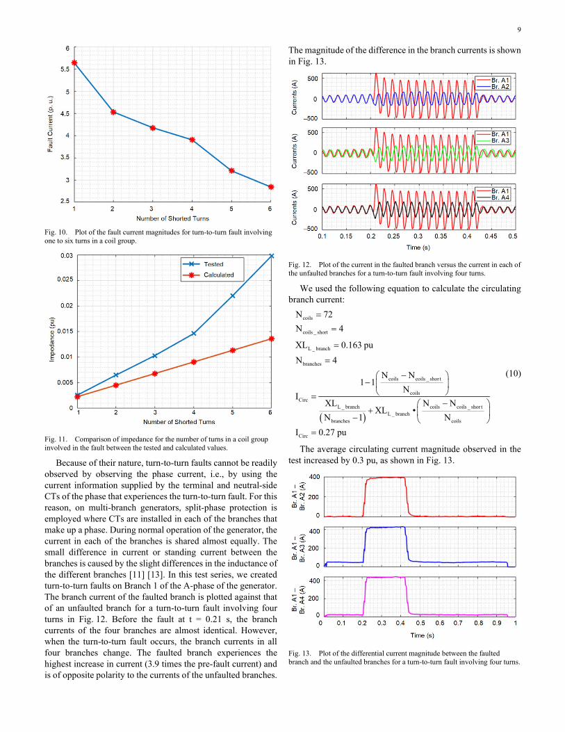
C. Turn-to-Turn Fault (on the Same Branch) The fault current magnitudes for the turn-to-turn fault series
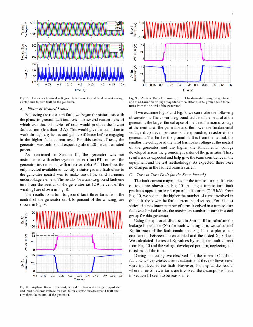
of tests are shown in Fig. 10. A single turn-to-turn fault produces approximately 5.6 pu of fault current (7.19 kA). From Fig. 10, we see that the higher the number of turns involved in the fault, the lower the fault current that develops. For this test series, the maximum number of turns involved in a turn-to-turn fault was limited to six, the maximum number of turns in a coil group for this generator.
Using the approach discussed in Section III to calculate the leakage impedance (XL) for each winding turn, we calculated XL for each of the fault conditions. Fig. 11 is a plot of the comparison between the calculated and the tested XL values. We calculated the tested XL values by using the fault current from Fig. 10 and the voltage developed per turn, neglecting the resistance of the turn.
During the testing, we observed that the internal CT of the fault switch experienced some saturation if three or fewer turns were involved in the fault. However, looking at the results where three or fewer turns are involved, the assumptions made in Section III seem to be reasonable.
9
Fig. 10. Plot of the fault current magnitudes for turn-to-turn fault involving one to six turns in a coil group.
Fig. 11. Comparison of impedance for the number of turns in a coil group involved in the fault between the tested and calculated values.
Because of their nature, turn-to-turn faults cannot be readily observed by observing the phase current, i.e., by using the current information supplied by the terminal and neutral-side CTs of the phase that experiences the turn-to-turn fault. For this reason, on multi-branch generators, split-phase protection is employed where CTs are installed in each of the branches that make up a phase. During normal operation of the generator, the current in each of the branches is shared almost equally. The small difference in current or standing current between the branches is caused by the slight differences in the inductance of the different branches [11] [13]. In this test series, we created turn-to-turn faults on Branch 1 of the A-phase of the generator. The branch current of the faulted branch is plotted against that of an unfaulted branch for a turn-to-turn fault involving four turns in Fig. 12. Before the fault at t = 0.21 s, the branch currents of the four branches are almost identical. However, when the turn-to-turn fault occurs, the branch currents in all four branches change. The faulted branch experiences the highest increase in current (3.9 times the pre-fault current) and is of opposite polarity to the currents of the unfaulted branches.
The magnitude of the difference in the branch currents is shown in Fig. 13.
Fig. 12. Plot of the current in the faulted branch versus the current in each of the unfaulted branches for a turn-to-turn fault involving four turns.
We used the following equation to calculate the circulating branch current:
( )
coils
coils _ short
L _ branch
branches
coils coils _ shor t
coilsCirc
L _ branch coils coils _ shor tL _ branch
branches coils
Circ
N 72N 4
XL 0.163 puN 4
N N1 1
NI
XL N NXL •
N 1 NI 0.27 pu
==
=
=
− −
=−
+ − =
(10)
The average circulating current magnitude observed in the test increased by 0.3 pu, as shown in Fig. 13.
Fig. 13. Plot of the differential current magnitude between the faulted branch and the unfaulted branches for a turn-to-turn fault involving four turns.

10
D. Phase-to-Phase Fault For this test, we connected the generator to the power system
(i.e., the generator breaker was closed). The fault switch was connected between the A-phase, one turn from the neutral (F2) and the B-phase, and two turns from the neutral (F9). This is effectively a phase-to-phase fault close to the neutral of the generator. Fig. 14 shows a plot of the fault current in the A-phase generator and neutral CTs. A plot of the calculated operating and restraint is also shown in Fig. 14.
Using IOP-CALC and IRT-CALC, we created the percentage differential plot shown in Fig. 15.
Fig. 14. Plot of the A-phase neutral and terminal CTs for a phase-to-phase fault close to the neutral of the generator. Also shown is a plot of the calculated operating (IOP-CALC) and restraint (IRT-CALC) currents.
Fig. 15. Plot of the percentage differential for the phase-to-phase fault close to the neutral of the generator using a slope of 35 percent.
Fig. 15 shows that the differential element will readily detect a phase-to-phase fault at this location.
After the first test was successful, an Avista engineer asked, “What would a 100 percent phase-to-phase fault look like?” We replied, “Let us see.” The generator was then readied for a
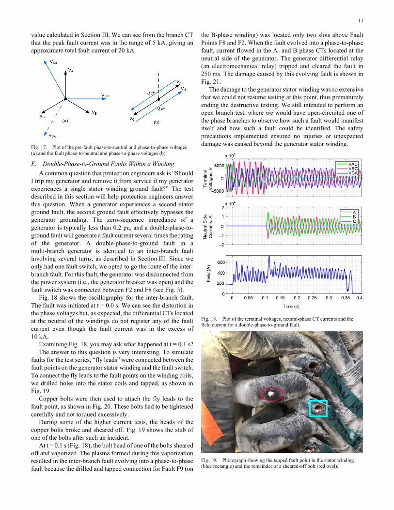
100 percent AB fault. The generator was disconnected from the power system (i.e., the generator breaker was opened). The fault switch was connected between the A-phase terminal connection and the B-phase terminal connection (T1-to-T3) in Fig. 3. Fig. 16 shows that the VAB voltage collapsed and the VBC and the VCA voltages increased when the fault was initiated.
Fig. 16. Plot of the terminal voltages, the phase currents measured by the neutral-side CT of the generator, the current measured by the individual branch CTs involved in the phase, and the field current for a 100 percent AB fault with the generator offline.
At first glance, it appeared as if the generator went into saturation, but this was not the case. Recall that the PT at the generator terminal is an open-delta PT. Pre-fault, the phase-to-phase voltages were of equal magnitude and balanced, as can be seen in Fig. 17a. However, when the fault was initiated, the line-to-ground voltages of the A and B phases decreased. The generator automatic voltage regulator (AVR) was in auto mode. When the AVR detected the drop in terminal voltage (i.e., below 1 pu), it boosted the field current as can be seen in Fig. 16, to increase the terminal voltage of the generator back to 1 pu. This increase in the field current increased the generator internal voltage (EMF), which increased the voltage magnitude of all three phases. It is this increase of the generator voltage that ultimately resulted in the saturation of the open-delta PT. The A- and B-phase voltages also shifted into phase with one another so that the potential difference between them became zero (as is expected for a phase-to-phase fault at the measuring point.) This shift in the line-to-neutral voltages resulted in an increase in the VBC and VCA voltages, as can be seen in Fig. 17b. This increase of VBC and VCA resulted in the PT becoming saturated and the voltage becoming distorted.
We observed that the CTs in the generator neutral (used for differential protection) also saturated. The fault was initiated close to voltage zero; therefore, the current had a large dc offset, which contributed to the rapid saturation of the CTs. However, we observed that as the fault progressed, the CTs began to pull out of saturation and the steady-state values approached the
11
value calculated in Section III. We can see from the branch CT that the peak fault current was in the range of 5 kA, giving an approximate total fault current of 20 kA.
Fig. 17. Plot of the pre-fault phase-to-neutral and phase-to-phase voltages (a) and the fault phase-to-neutral and phase-to-phase voltages (b).
E. Double-Phase-to-Ground Faults Within a Winding A common question that protection engineers ask is “Should
I trip my generator and remove it from service if my generator experiences a single stator winding ground fault?” The test described in this section will help protection engineers answer this question. When a generator experiences a second stator ground fault, the second ground fault effectively bypasses the generator grounding. The zero-sequence impedance of a generator is typically less than 0.2 pu, and a double-phase-to-ground fault will generate a fault current several times the rating of the generator. A double-phase-to-ground fault in a multi-branch generator is identical to an inter-branch fault involving several turns, as described in Section III. Since we only had one fault switch, we opted to go the route of the inter-branch fault. For this fault, the generator was disconnected from the power system (i.e., the generator breaker was open) and the fault switch was connected between F2 and F8 (see Fig. 3).
Fig. 18 shows the oscillography for the inter-branch fault. The fault was initiated at t = 0.0 s. We can see the distortion in the phase voltages but, as expected, the differential CTs located at the neutral of the windings do not register any of the fault current even though the fault current was in the excess of 10 kA.
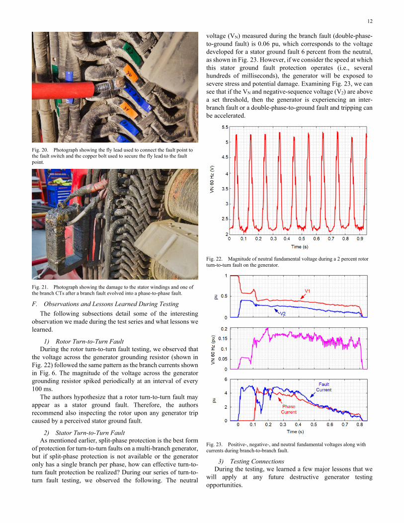
Examining Fig. 18, you may ask what happened at t = 0.1 s? The answer to this question is very interesting. To simulate
faults for the test series, “fly leads” were connected between the fault points on the generator stator winding and the fault switch. To connect the fly leads to the fault points on the winding coils, we drilled holes into the stator coils and tapped, as shown in Fig. 19.
Copper bolts were then used to attach the fly leads to the fault point, as shown in Fig. 20. These bolts had to be tightened carefully and not torqued excessively.
During some of the higher current tests, the heads of the copper bolts broke and sheared off. Fig. 19 shows the stub of one of the bolts after such an incident.
At t = 0.1 s (Fig. 18), the bolt head of one of the bolts sheared off and vaporized. The plasma formed during this vaporization resulted in the inter-branch fault evolving into a phase-to-phase fault because the drilled and tapped connection for Fault F9 (on
the B-phase winding) was located only two slots above Fault Points F8 and F2. When the fault evolved into a phase-to-phase fault, current flowed in the A- and B-phase CTs located at the neutral side of the generator. The generator differential relay (an electromechanical relay) tripped and cleared the fault in 250 ms. The damage caused by this evolving fault is shown in Fig. 21.
The damage to the generator stator winding was so extensive that we could not resume testing at this point, thus prematurely ending the destructive testing. We still intended to perform an open branch test, where we would have open-circuited one of the phase branches to observe how such a fault would manifest itself and how such a fault could be identified. The safety precautions implemented ensured no injuries or unexpected damage was caused beyond the generator stator winding.
Fig. 18. Plot of the terminal voltages, neutral-phase CT currents and the field current for a double-phase-to-ground fault.
Fig. 19. Photograph showing the tapped fault point in the stator winding (blue rectangle) and the remainder of a sheared-off bolt (red oval).
12
Fig. 20. Photograph showing the fly lead used to connect the fault point to the fault switch and the copper bolt used to secure the fly lead to the fault point.
Fig. 21. Photograph showing the damage to the stator windings and one of the branch CTs after a branch fault evolved into a phase-to-phase fault.
F. Observations and Lessons Learned During Testing The following subsections detail some of the interesting
observation we made during the test series and what lessons we learned.
1) Rotor Turn-to-Turn Fault During the rotor turn-to-turn fault testing, we observed that
the voltage across the generator grounding resistor (shown in Fig. 22) followed the same pattern as the branch currents shown in Fig. 6. The magnitude of the voltage across the generator grounding resistor spiked periodically at an interval of every 100 ms.
The authors hypothesize that a rotor turn-to-turn fault may appear as a stator ground fault. Therefore, the authors recommend also inspecting the rotor upon any generator trip caused by a perceived stator ground fault.
2) Stator Turn-to-Turn Fault As mentioned earlier, split-phase protection is the best form
of protection for turn-to-turn faults on a multi-branch generator, but if split-phase protection is not available or the generator only has a single branch per phase, how can effective turn-to-turn fault protection be realized? During our series of turn-to-turn fault testing, we observed the following. The neutral
voltage (VN) measured during the branch fault (double-phase-to-ground fault) is 0.06 pu, which corresponds to the voltage developed for a stator ground fault 6 percent from the neutral, as shown in Fig. 23. However, if we consider the speed at which this stator ground fault protection operates (i.e., several hundreds of milliseconds), the generator will be exposed to severe stress and potential damage. Examining Fig. 23, we can see that if the VN and negative-sequence voltage (V2) are above a set threshold, then the generator is experiencing an inter-branch fault or a double-phase-to-ground fault and tripping can be accelerated.
Fig. 22. Magnitude of neutral fundamental voltage during a 2 percent rotor turn-to-turn fault on the generator.
Fig. 23. Positive-, negative-, and neutral fundamental voltages along with currents during branch-to-branch fault.
3) Testing Connections During the testing, we learned a few major lessons that we
will apply at any future destructive generator testing opportunities.

13
One major lesson we learned was that we need a better way to secure the fault switch fly leads to the fault points. At the time, drilling holes into the stator winding and tapping them seemed the best method. Copper is a relatively soft metal and torqueing the bolts too much risks stripping the tapped thread. Also, using copper bolts is not optimal because the force created during a high-current fault can easily shear a copper bolt.
The second major lesson we learned is to not leave an unused fault point exposed because, if for some reason a fly lead breaks loose or a piece of metal breaks loose and vaporizes, that vapor can become a plasma which can then result in an unanticipated fault condition. During the inter-branch fault, we did not anticipate that a sheared-off copper bolt could vaporize and create a plasma that would change the inter-branch fault into a phase-to-phase fault. This omission in our planning resulted in a premature end to the destructive testing.
V. CONCLUSION Faults on synchronous generators are rare. As such, good
recordings of such events are not generally available. A destructive fault test is the closest analog to an actual fault. The tests summarized in this paper simulated most of the winding failures that can occur on a synchronous generator. The resulting currents and voltages were captured with a high degree of fidelity. In addition, quantities were captured that are
not normally available from fault records, including high-resolution field measurements, individual branch currents, and the current at the fault point.
These data show interesting characteristics. For example, the impact of the unbalanced flux resulting from a rotor turn fault is noticeable in the branch currents and in the neutral voltage.
The primary consideration for these tests was the safety of the site personnel. Another important consideration was the need to confine any damage to the stator winding of the generator under test.
Since destructive fault tests are rarely carried out, detailed planning is very important. For example, calculations are required to ensure that the test equipment can carry and interrupt the worst-case fault current. The planning proved its value for unanticipated occurrences during these tests.
In the future, we plan to use the captured data to do more detailed validation of the effectiveness of existing protection functions. The data will be used for validation of the latest simulation software tools and should also provide insight into enhanced or novel generator protection functions.
VI. APPENDIX The layout of the test equipment and measuring points for
the destructive testing of the Little Falls generator is shown in Fig. 24, which also shows all the measuring points and where and at which rate the data were acquired.
Fig. 24. Layout of test and measuring devices for the Little Falls destructive testing.

14
Fig. 25. Picture of the destructive testing team showing the generator and turbine in the background.
VII. ACKNOWLEDGMENT The authors recognize that to perform destructive testing on
a generator requires the knowledge and assistance of many qualified and enthusiastic individuals. The authors would like to thank the following individuals for the help and assistance during this testing: Mr. Howard Johnson (Avista), Mr. Tom Berg (Avista), Mrs. Amber Blackstock (Avista), and Dr. Brian Johnson (University of Idaho), plus the operators and mechanical crew at Little Falls. A picture of the team that was involved in the destructive testing is shown in Fig. 25.
VIII. REFERENCES [1] D. L. Evans, “IEEE Working Group Report of Problems With
Hydrogenerator Thermoset Stator Windings Part I-Analysis of Survey,” IEEE Transactions on Power Apparatus and Systems, Vol. PAS-100, Issue 7, July 1981, pp. 3,284–3,291.
[2] N. Fischer, D. Finney, and D. Taylor, “How to Determine the Effectiveness of Generator Differential Protection,” proceedings of the 67th Annual Conference for Protective Relay Engineers, College Station, TX, March 2014.
[3] G.C. Stone, E.A. Boulter, I. Culbert, and H. Dhirani, Electrical Insulation For Rotating Machines, IEEE Press, 2004.
[4] P. Tavner, L. Ran, J. Penman, and H. Sedding, Condition Monitoring of Rotating Electrical Machines, The Institution of Engineering and Technology, London, United Kingdom, 2008.
[5] G. Koeppl and D. Braun, “New Aspects for Neutral Grounding of Generators Considering Intermittent Faults,” September 2010.
[6] R. Chowdhury, D. Finney and N. Fischer, “Using the Multi-Loop Fault Analysis Method for Setting and Evaluating Generator Protection Elements,” proceedings of the 71st Annual Conference for Protective Relay Engineers, College Station, TX, 2018.
[7] B. Kasztenny, N. Fischer, and H. J. Altuve, “Negative-Sequence Differential Protection – Principles, Sensitivity, and Security,” proceedings of the 68th Annual Conference for Protective Relay Engineers, College Station, TX, March 2015.
[8] B. Kasztenny, N. Fischer, H. J. Altuve, and D. Taylor, “Generator Turn-to-Turn Fault Protection Using a Stator-Rotor-Bound Differential Element,” proceedings of the Southern African Power System Protection & Automation Conference, Johannesburg, South Africa, November 2017.
[9] A. E. Fitzgerald, C. Kingsley Jr., and S.D. Umans, Electric Machinery, Fifth Edition, McGraw-Hill Publishing Company, New York, NY, 1990.
[10] M. Alla, “Analysis of Synchronous Machine Turn-to-Turn Fault Currents,” M.S. Thesis, University of Idaho, ProQuest Dissertations Publishing, Publication Number 10268575, May 2017.
[11] H. R. Sills and J. L. McKeever, “Characteristics of Split-Phase Currents as a Source of Generator Protection,” Transactions of the American Institute of Electrical Engineers. Part III: Power Apparatus and Systems, Vol. 72, Issue: 5, October 1953, pp. 11,005–11,016.
[12] E.W. Kimbark Power System Stability, Volume III: Synchronous Machines, IEEE Press, 1995.
[13] S. Kim, D. Finney, N. Fischer, and B. Kasztenny, “CT Requirements for Generator Split-Phase Protection,” proceedings of the 38th Annual Western Protective Relay Conference, Spokane, WA, October 2011.
IX. BIOGRAPHIES Calvin Howard received his BS and MS in electrical engineering from Portland State University in 2012 and 2013. Upon graduating, he joined POWER Engineers as a system studies and protection engineer in the SCADA and Analytical Services division. In 2016, Calvin joined the system protection department at Avista Utilities. Calvin has broad experience in the field of power system operations, maintenance, modeling, and protection. Calvin is a registered professional engineer in Washington State and a member of the IEEE Power and Energy Society.
Beth Andrews graduated from Gonzaga University in 2015 with a B. S. in electrical engineering. After graduation, she joined Avista Utilities in the System Protection group where she has spent the last four years developing a deeper understanding of protection systems. She is an IEEE member and currently the Vice Chair of the Spokane Section Young Professionals. She is a registered EIT in Washington.

15
Douglas Taylor received his BSEE and MSEE degrees from the University of Idaho in 2007 and 2009. He joined Schweitzer Engineering Laboratories, Inc. in 2009 and worked as a protection engineer and research engineer in the Research and Development division. Currently, Doug is working as a protection engineer at Avista Utilities. He is a registered professional engineer in the state of Washington and is a member of the IEEE. His main interests are power system protection and power system analysis. Doug holds 3 patents and has helped author more than 15 technical papers in the area of power system protection.
Normann Fischer received a Higher Diploma in Technology, with honors, from Technikon Witwatersrand, Johannesburg, South Africa, in 1988; a BSEE, with honors, from the University of Cape Town in 1993; an MSEE from the University of Idaho in 2005; and a PhD from the University of Idaho in 2014. He joined Eskom as a protection technician in 1984 and was a senior design engineer in the Eskom protection design department for three years. He then joined IST Energy as a senior design engineer in 1996. In 1999, Normann joined Schweitzer Engineering Laboratories, Inc., where he is currently a fellow engineer in the research and development division. He was a registered professional engineer in South Africa and a member of the South African Institute of Electrical Engineers. He is currently a senior member of IEEE and a member of the American Society for Engineering Education (ASEE). Normann has authored over 60 technical and 10 transaction papers and 20 patents related to electrical engineering and power system protection.
Dale Finney received his bachelor of engineering degree from Lakehead University and his master of engineering degree from the University of Toronto. He began his career with Ontario Hydro, where he worked as a protection and control engineer. Currently, Mr. Finney is employed as a principal power engineer with Schweitzer Engineering Laboratories, Inc. His areas of interest include generator protection, line protection, and substation automation. Mr. Finney holds more than 10 patents and has authored more than 30 papers in the area of power system protection. He is a member of the main committee and chair of the rotating machinery subcommittee of the IEEE PSRC. He is a senior member of the IEEE and a registered professional engineer in the province of Nova Scotia.
Matchyaraju Alla received his bachelor of engineering degree from Gitam University, India, in 2010 and his master of engineering degree from the University of Idaho, USA, in 2017. He received his post-graduate diploma in thermal power plant engineering from National Power Training Institute, India, in 2012. He began his career with Vedanta Resources PLC, where he worked in generator protection and control and was in charge of testing and commissioning three 660 MW thermal power plants. Since 2016, Mr. Raju has been employed as a power engineer with Schweitzer Engineering Laboratories, Inc. His areas of interest include generator protection, transformer protection, and motor protection. He is a member of IEEE.
© 2019, 2020 by Avista Utilities and
Schweitzer Engineering Laboratories, Inc. All rights reserved.
20200309 • TP6930-01