Embed Size (px)
Citation preview

1
Lesson 8 GMPLS (Generalized Multi-protocol Label Switching)
Objectives :GMPLS is a protocol that is applied to the TDM layer, the wavelength-path layer, and the fiber layer by generalizing the label concept of MPLS. GMPLS makes it possible to execute distributed control ― a feature of MPLS ― thereby simplifying the operation. It is also possible to totally engineer the traffic based on the traffic information or topology information of each layer and to improve the utilization efficiency of the network.

2Fig.8.1
Network layer structure
Packet layer
TDM layer
Fiber layer
TDM layer
Fiber layer
Packet layer
layer
Fiber layer
Packet layer
layer
(a) (b) (c)
20052000 2010
(a) (b) (c)

3Fig.8.3
IP packet
(a) Packet
Label
…
… …
(b) TDM
…
Time slot
Wavelength
(c) λ
Link
Link
Link
Link
(d) Fiber
…
Fiber
Concept of label
MPLS Shim header
Time Slot #
λ1 : Red
λ2 : Blue
Fiber #

4Fig.8.4
FSC-LSP
LSC-LSP TDM-LSP PSC-LSP
Hierarchization of LSP
LSP : Label Switching Path

5Fig.8.5
LSCTDMPSC FSC FSC
TDM region
PSC region
LSC region
FSC region
LSC TDM PSC
PSC: Packet Switching CapabilityTDM: Time Division MultiplexingLCS: Lambda Switching CapabilityFSC: Fiber Switching Capability
Relationship between the switching capability and the region

6Fig.8.6
Packet layer(Distributed control)
TDM layer(Distributed control)
λ-layer(Distributed control)
Fiber layer
Central controlling device
Central controlling device
Current IP/MPLS network

7Fig.8.7
Packet layer(Distributed control)
TDM layer(Distributed control)
Fiber layer
λ-layer(Central control)
GMPLS network of which each layer is used distributed control method

8Fig.8.8
Fiber layer
Packet layer+
TDM layer+
λ-layer
(Distributed control)
GMPLS network that is controlled distributtedly and integratedly with multiple layers
Integrated traffic engineering = Multi-layer TE

9Fig.8.9
Fiber layerλ-layerPacket layer
Multi-layer traffic engineering

10Fig.8.10
RSVP-TE extensionOSPF extension LMP
GMPLS architecture
Major protocols of GMPLS
OSPF-TE : Routing
RSVP-TE : Signaling
LMP : Link Management Protocol

11Fig.8.11(b) Physical link topology
A
B C
D
E
Packet layerTE link
A
B C
DE
TDM layer
TDM LSP
(a) TE link topology
Concept of TE (Traffic Engineering)
TE Link
A→E direct link for packet layer

12Fig.8.12
Opaque LSA format (RFC2370)
0 1 2 3 4 5 6 7 8 9 0 1 2 3 4 5 6 7 8 9 0 1 2 3 4 5 6 7 8 9 0 1
+-+-+-+-+-+-+-+-+-+-+-+-+-+-+-+-+-+-+-+-+-+-+-+-+-+-+-+-+-+-+-+-+| LS age | Options |Link-state type|+-+-+-+-+-+-+-+-+-+-+-+-+-+-+-+-+-+-+-+-+-+-+-+-+-+-+-+-+-+-+-+-+| Opaque Type | Instance |+-+-+-+-+-+-+-+-+-+-+-+-+-+-+-+-+-+-+-+-+-+-+-+-+-+-+-+-+-+-+-+-+| Advertising Router |+-+-+-+-+-+-+-+-+-+-+-+-+-+-+-+-+-+-+-+-+-+-+-+-+-+-+-+-+-+-+-+-+| LS Sequence Number |+-+-+-+-+-+-+-+-+-+-+-+-+-+-+-+-+-+-+-+-+-+-+-+-+-+-+-+-+-+-+-+-+| LS checksum | Length |+-+-+-+-+-+-+-+-+-+-+-+-+-+-+-+-+-+-+-+-+-+-+-+-+-+-+-+-+-+-+-+-+| |+ +| Opaque Information |+ +| ... |
0 1 2 3 4 5 6 7 8 9 0 1 2 3 4 5 6 7 8 9 0 1 2 3 4 5 6 7 8 9 0 1+-+-+-+-+-+-+-+-+-+-+-+-+-+-+-+-+-+-+-+-+-+-+-+-+-+-+-+-+-+-+-+-+| Sub-TVL Type | length |+-+-+-+-+-+-+-+-+-+-+-+-+-+-+-+-+-+-+-+-+-+-+-+-+-+-+-+-+-+-+-+-+| Value... |+-+-+-+-+-+-+-+-+-+-+-+-+-+-+-+-+-+-+-+-+-+-+-+-+-+-+-+-+-+-+-+-+
1
10 Advertisement within areaNumber attached to identify the multiple traffic engineering LSAs
Indicates traffic engineering LSA
1-9 (MPLS extension)11,14,15,16 (GMPLS extension)
Length of Sub-TLV

13Fig. 8.13
1 1 Link type2 4 Link ID3 4 Local interface IP address4 4 Remote interface IP address5 4 Traffic engineering metric6 4 Maximum bandwidth7 4 Maximum reservable bandwidth8 32 Unreserved bandwidth9 4 Administrative group11 8 Link Local/Remote Identifiers 14 4 Link Protection Type15 variable Interface Switching Capability Descriptor16 variable Shared Risk Link Group
Added for GMPLSAdded for GMPLSAdded for GMPLSAdded for GMPLS
Sub-TLVType Length Name
Sub-TLV of opaque LSA in GMPLS OSPFOpaque ←→ transparent
Numbered link = IP address is assigned to link
Un-numbered link = Router ID + Link ID

14Fig.8.14
A B C D
PATH PATH PATH
RESV RESV RESV
Label request
Originating node Destination node
Label
{301}{201}{101}Label
PATH message and RESV message

15Fig.8.17
Terminator(Destination node)
A B C DPATH PATH PATH
RESV RESV RESV
Initiator(Originating node)
{505}
Upstream label
{613} {658}
{301}{201}{101}(Downstream) label
Upstream label Upstream label
Switch setup Switch setup
Upstream labelMPLS = One-Way path
GMPLS (TDM and λ , fiber) = Bidirectional Path
Downstream Upstream Bath label can be assigned simultaneously

16Fig.8.18
Label set
Input Output Wavelength
101 201 Red115 215 Yellow120 220 Green150 250 Blue
Input Output Wavelength
201 301 Red215 315 Yellow220 320 Green250 350 Blue
Correspondence table between wavelength and label (node-B)
A B C DPATH PATH PATH
RESV RESV RESV
Originating node Destination node
{101, 115, 120, 150}
Label set
{201, 220, 250} {301, 350}
{301}{201}{101}
Assigned label
Correspondence table between wavelength and label (node-C)
If the wavelength converter is not exist, the label or wavelength which can be reserved all the links.

17Fig.8.19
Node-1 Node-2 Node-3 Node-4 Node-5
PATH (PSC)
PATH (LSC)PATH (LSC)
RESV (LSC)RESV (LSC)
PATH (PSC)PATH (PSC)
RESV (PSC)
RESV (PSC)
RESV (PSC)
LSC-LSPPSC-LSP
Hierarchization of LSPTriggered Signaling
Hierarchical Signaling

18Fig.8.20
OC-48c
OC-192c
OC-192
(a) Port
(b) Component link
OC-192c
OC-192c
TE-link(bundling)
Port
OC-192
OC-192
TE-link(bundling)
Component link
Label
Types of data link, Port and component link
Port : Minimum physical link that cannot be divided anymore
Component link : Minimum physical link that can be divided by using time-slot or a shim label

19
Link Management Protocol : LMP
・Control channel management“LMP neighbors”= establish and manage the control channel
・Link-property correlationPort or component link?
・Connectivity certificationTest message using data link
・Failure management
“Channel status”
“Channel status Ack”
downstream

20Fig.8.21
Node-A(Local)
Node-B(Remote)
TE-link
Control channel
Link identifier
13
14
25
26
Link management by LMP
10
11
12
1
2
3
1
2
3
10
1112
Interface identifier
IP network
101
Label
102
103
101102
103
Link management protocol

Multi-layer TE enable GMPLS Node
21
FiberLayer
Layer
Packet Layer
layer topology
Packet layer topology
IP packet traffic monitor
TE Engine Extended OSPF
Extended RSVP
GMPLS Controller
GMPLS Control Unit
Packet Switching
Switching

Trade-off between Node cost and Link cost
22
Node1
Node2
Node3 Node4Node5
Node6
Node1
Node2
Node3 Node4
Node5
Node6
Fiber
LSC LSP
(a) Link cost>Node cost
(b) Node cost>Link cost
Node Link

GMPLS Control Flexible Network Topology
23
0 500 1000 1500 2000 25000
0.2
0.4
0.6
0.8
1Fixed Topology
Cost Reduction
Traffic Demand
Net
wor
k Cos
t (A
rv. U
nit)
Flexible Topology

Optical Crossconect Architecture
24
Input port#0
Input port#1
Output port#0
Output port#1
Wavelength Converter
Wavelength Demultiplexer Wavelength MultiplexerSwitching Block
Input port#0
Input port#1
Output port#0
Output port#1
Wavelength Converter
(a) Wavelength Converter at each output line
(b) Shared Wavelength Converter

25Figure 9.34.
Examples of AND usageSource Destination
WC WCAvailableUnavailable 1 2 3 4 1 2 3 4 1 2 3 4
1 0 1 1 0 0 1 1 0 0 1 0
Link A Link B Link C
Selected wavelength 3-3-3
1 2 3 4 1 2 3 4 1 2 3 4
1 0 1 1 0 0 1 1 1 0 0 0
Selected wavelength 3-3-1
(a) Case 1
(b) Case 2
Wavelengthconversion
Node 1 Node 2
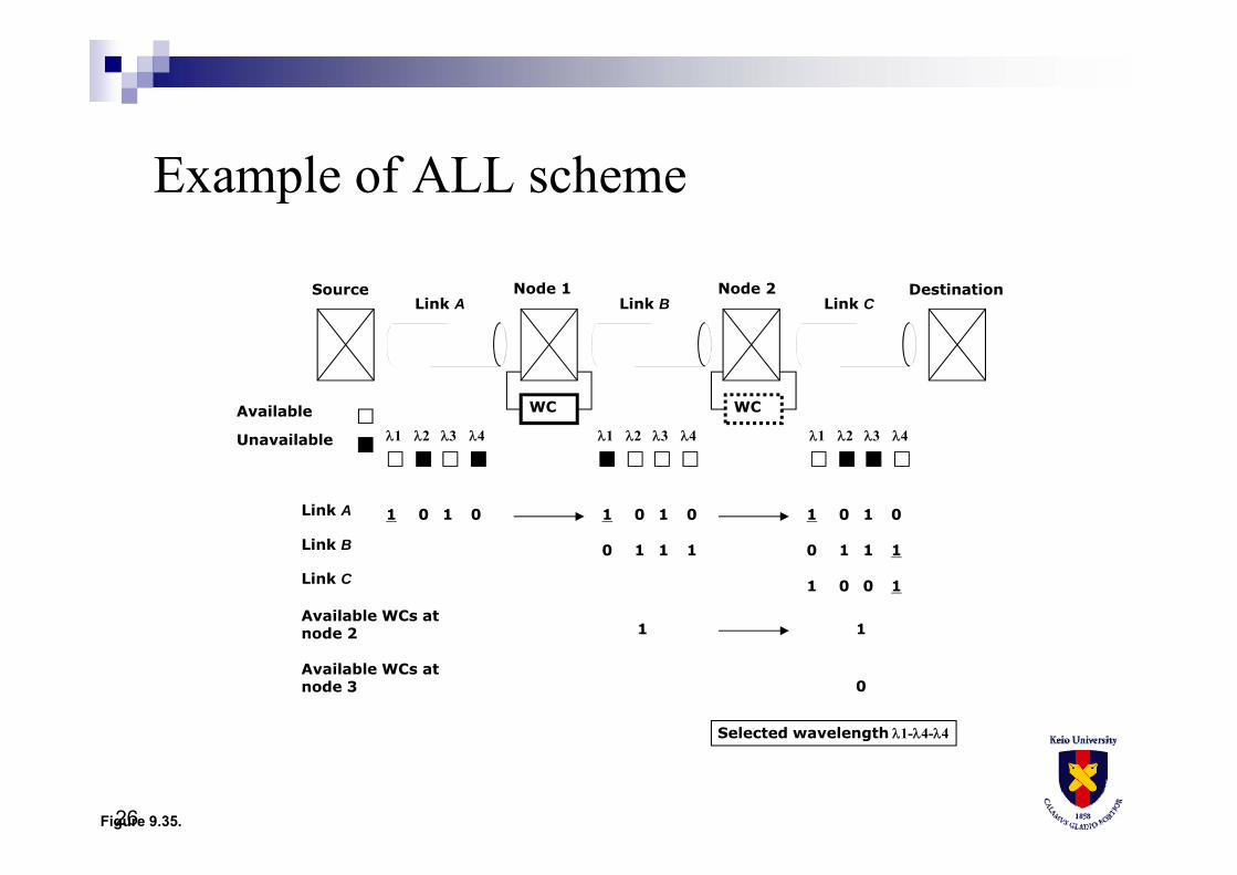
26
WC WCAvailable
Unavailable 1 2 3 4 1 2 3 4 1 2 3 4
1 0 1 0 1 0 1 0 1 0 1 0
0 1 1 1
1 0 0 1
0 1 1 1
Source DestinationLink A Link B Link C
Link A
Link B
Link C
Available WCs at node 2
Node 1 Node 2
Available WCs at node 3
1 1
0
Selected wavelength 1-4-4
Figure 9.35.
Example of ALL scheme

27
Source Destination
0
1 2
4
3
6srlg(2, 6, 0)=1
srlg(5, 6, 0)=1
COSPF(0, 4)=1.5
COSPF(5, 6)=1
COSPF(0, 1)=1 COSPF(1, 2)=1 COSPF(2, 6)=1
COSPF(3, 6)=1.5COSPF(1, 3)=1
5
COSPF(4, 5)=1
Figure 9.41.
Network example
COSPF ( i, j ) : link costsrlg ( i, j, g ) = 0 doesn’t belong to ―srlg ( i, j, g ) = 0 belong to srlg “1”

28
Node 5
Node 2
Node 6
Fiber
λ1
λ2
Optical crossconnect
SRLG #0
Figure 9.42.
SRLG example
Node 5 → 6
Node 2 → 6Same srlg #0

29
Source Destination
0
1 2
4
3
6
5
Figure 9.43.
Example of conventional disjoint path selection algorithm
These links are same srlg No.

30
Source Destination
0
1 2
4
3
6
5
Figure 9.44.
Example of WSRLG path selection algorithm
These two link cost become large, because srlg shared link.
“ SRLG disjoint ”
Waited-SRLG Path selection

31
Single control plane
LSC path
IP router
OXC
IP router
Fig.8.22
Peer model
All the IP router

32Fig.8.23
IP router
OpticalUNI
OpticalUNI
IP control plane(Client)
Optical control plane(Server) LSC path
IP router
Overlay model

Topology reconfiguration
Midori : Automatic Self-configured Network Topology (Experimental)
Layer‐2 Switches
ON
OFFAC
meter
MiDORi PCE
Traffic Generators

34
Conclusions for Lesson8
Basic concept of GMPLS has been described.
GMPLS is extended MPLS label to TDM time-slot
or Lambda wavelength. It introduced TE-link for
lower layer topology. Signaling, Routing and LMP
are important.


![Internet-Draft draft-ali-pce-remote-initiated-gmpls-lsp-02 · - GMPLS also specifics support for asymmetric bandwidth requests [RFC6387]. - GMPLS extends the addressing to include](https://img.pdfslide.us/doc/110x75/5b1e55d57f8b9a116d8b6ebe/internet-draft-draft-ali-pce-remote-initiated-gmpls-lsp-02-gmpls-also-specifics.jpg)