Embed Size (px)
Citation preview

1/15/2016
1
LESSON 20 ALTERNATOR OPERATION OF
SYNCHRONOUS MACHINES
ET 332b
Ac Motors, Generators and Power Systems
1
Lesson 20_et332b.pptx
LEARNING OBJECTIVES
Lesson 20_et332b.pptx
2
After this presentation you will be able to:
Interpret alternator phasor diagrams under different
load conditions.
Explain the infinite bus concept and compute power
delivered to an infinite bus.
Explain how alternators are synchronized.
Define alternator stiffness.

1/15/2016
2
ALTERNATOR OPERATION
Lesson 20_et332b.pptx
3
Synchronous machines can convert from motor to generator operation by
having the shaft driven by a source of mechanical power
Note: reversal of current direction in
machine electrical model
Current exits for
generator
operation
PHASOR DIAGRAMS OF MACHINE OPERATION
Lesson 20_et332b.pptx
4
Motor operation: d lags the terminal voltage VT. Armature current Ia can
either lead or lag VT depending on value of excitation.
Lagging Ia
Leading Ia
1/15/2016
3
Lesson 20_et332b.pptx
5
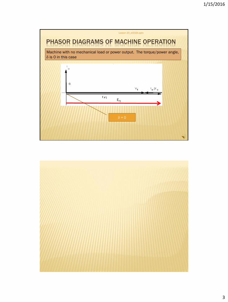
PHASOR DIAGRAMS OF MACHINE OPERATION
Machine with no mechanical load or power output. The torque/power angle,
d is 0 in this case
d = 0
Ef1
PHASOR DIAGRAMS OF MACHINE OPERATION
Lesson 20_et332b.pptx
6
Generator operation (Alternator) Ef1 leads the terminal
voltage for generator
operation
Power factor angle can either
lag or lead depending on field
excitation

1/15/2016
4
ALTERNATOR CIRCUIT MODEL
Lesson 20_et332b.pptx
7
Synchronous Generator Equations and Model Circuit
Ia reversed
)sin(X
EVP
s
fT
in d
Power equation (Watts/phase)
Note: equation is positive and d is positive for
Alternator (generator) operation
safT jXIEV
Voltage equation
Where: VT = terminal voltage/phase (V)
Ef = excitation voltage/phase (V)
Ia = armature current/phase (A)
Xs = synchronous reactance/phase (ohms)
Governor
GENERATOR LOADING
Lesson 20_et332b.pptx
8
Prime Mover Generator
Mechanical power
converted to active
power
Exciter Excess field
flux converted
to reactive power
ELECTRIC
LOADS
Pmech
Idc
Pe
Q
Electrical load produces
counter-torque
Prime
Mover
Torque
Increased electrical load produces counter torque that
prime mover must overcome or prime mover slows down
Speed Governor – device that regulates
speed to match electric load

1/15/2016
5
INFINITE BUS CONCEPT
Lesson 20_et332b.pptx
9
In large power systems, VT and system frequency are assumed constant.
Individual generators added to large system can not change VT and f.
Good approximation when generator small with respect to all other
generation connected
Power Grid
(100’s of interconnected
generators. Psys = sum of
all generator’s outputs)
System Tie
Bus
Local Generator
Po <<< Psys VT and f
constant
here
INFINITE BUS EXAMPLE
Lesson 20_et332b.pptx
10
Example 20-1: 3-phase, 460 V, 2-pole, 60 Hz, wye-connected,
synchronous alternator. Xs = 1.26 ohm/phase. Connected to
an infinite bus and supplies 117 kW with a power angle of 25
degrees. Neglect losses and find:
a.) turbine torque supplied to alternator;
b.) excitation voltage;
c.) active, reactive power and machine power factor;
d.) neglecting saturation effects of the field, the excitation
voltage if the field current is reduced to 85% of its original
value in part a;
e.) the turbine speed for 60 Hz operation

1/15/2016
6
EXAMPLE 20-1 SOLUTION (1)
Lesson 20_et332b.pptx
11
Find torque developed by prime mover to generate 117 kW neglecting losses
Need synchronous speed
EXAMPLE 20-1 SOLUTION (2)
Lesson 20_et332b.pptx
12
Find the excitation voltage Ef
Solve for Ef

1/15/2016
7
EXAMPLE 20-1 SOLUTION (3)
Lesson 20_et332b.pptx
13
Part c.) Find Sout Pout and Qout of generator. Need armature current
EXAMPLE 20-1 SOLUTION (4)
Lesson 20_et332b.pptx
14
Find the power phasor using the following formulas

1/15/2016
8
EXAMPLE 20-1 SOLUTION (5)
Lesson 20_et332b.pptx
15
Find the power factor and the change in excitation voltage
PARALLELING SYNCHRONOUS GENERATORS
Lesson 20_et332b.pptx
16
:Required initial conditions : Machines must have same phase sequence (order
of voltages) (ABC) or (BAC). Incorrect phase sequence causes short circuit.
1.) Adjust voltage
of incoming
machine to
match system
voltage
VT
2.) Adjust
frequency of
incoming
generator to
match system f
(Synchronize to
system)
3.) Close
generator
breaker
Turbine speed
should be a
fraction of Hz
faster than
system to prevent
motoring of
generator

1/15/2016
9
MEASURING SYSTEM/MACHINE FREQUENCY
Lesson 20_et332b.pptx
17
Synchroscope - instrument to determine if machine frequency is the same
as system frequency. Instrument indicates fast-slow operation by
comparing the frequencies of the two voltages (system-generator)
t
0
gs dt )t(ffMathematically, phase
shift is integral of
frequency change
Where: = phase shift
fs = system frequency
fg(t) = generator frequency
SYNCH EXAMPLE
Lesson 20_et332b.pptx
18
Generator voltage lagging system voltage - crosses zero later in time
D
Closing Generator breaker with phase shifts of greater than 10 degrees causes high
armature currents and will trip the generator off line
Also cause
rotor
oscillations
which cause
the generator
to be unstable

1/15/2016
10
SYNCHRONIZING GENERATOR TO SYSTEM
Lesson 20_et332b.pptx
19
Increasing speed of prime mover increases frequency which reduces phase
difference
SYNCHRONIZING GENERATOR TO SYSTEM
Lesson 20_et332b.pptx
20
Phase shift near zero at ts. Prime mover is
accelerating the rotor ahead of the system
voltage after this point. (Vg leads Vs)
Close generator breaker
when phase is slightly
leading system
Machine will remain
locked to system
frequency after breaker
is closed assuming
infinite bus

1/15/2016
11
STIFFNESS OF SYNCHRONOUS MACHINES
Lesson 20_et332b.pptx
21
Stiffness -Ability of a synchronous machine to resist forces that pull it out of
synchronism. Slope of the power-angle curve around a given operating point
Operating point in graph above is at do
STIFFNESS OF SYNCHRONOUS MACHINES
Lesson 20_et332b.pptx
22
Remember power equation
)sin(X
EV3P
s
fT
d
To find slope, take derivative of P with respect to d. This is defined as
the stiffness
Units of Ps are watts/radian (or degree)
)cos(X
EV3
d
dPPP
s
fT
s d
d
dD
D

1/15/2016
12
STIFFNESS OF SYNCHRONOUS MACHINES
Lesson 20_et332b.pptx
23
Example 20-2: A 3-phase 13.2 kV 60 Hz, 50 MVA wye-
connected cylindrical rotor synchronous generator has Xs =
2.49 ohms/phase and an internally generated voltage at the
operating point of 15,767 VLL with a power angle of 11.1
degrees. The machine has 8 poles. Determine:
a.) the synchronizing power in MW/rad and MW/ mechanical
degree
b.) synchronizing torque in N-n/radian
EXAMPLE 20-2 SOLUTION (1)
Lesson 20_et332b.pptx
24
Find the per phase quantities of VT and Ef from the line-to-line values

1/15/2016
13
EXAMPLE 20-2 SOLUTION (2)
Lesson 20_et332b.pptx
25
Number of poles is 8, so... de= (dm) ∙(P/2)
b.) Now compute the synchronizing torque
Compute
synchronous speed
Convert to
Radians/second
ET 332b
Ac Motors, Generators and Power Systems
Lesson 20_et332b.pptx
26
END LESSON 20
ALTERNATOR OPERATION OF
SYNCHRONOUS MACHINES