Embed Size (px)
Citation preview

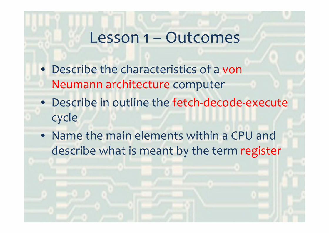
Lesson 1 – Outcomes
• Describe the characteristics of a von Neumann architecture computer
• Describe in outline the fetch‐decode‐executecycle
• Name the main elements within a CPU and describe what is meant by the term register

Early Computers• Before ‘memory’ existed …
– Programs – wired‐in to the hardware– Data – input on punched card or paper tape and output straight away
• John von Neumann – American mathematician – working on Manhattan Project in Los Alamos (making atomic bomb) used ENIAC machine
• Alan Turing – British mathematician – working at Bletchley Park – designed code breaking machines (later contributed to Colossus)
1.0 kB/s
1.4 kB/s
3000 kB/s

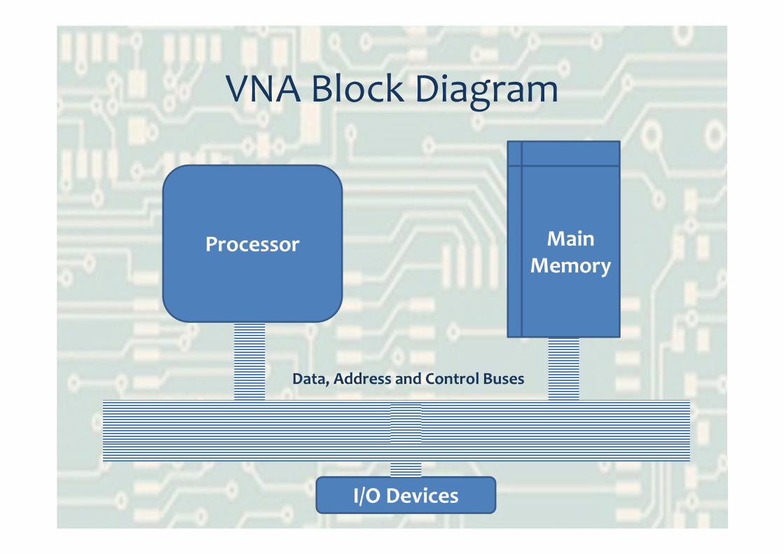
von Neumann Architecture• Means a stored program computer• The memory stores both program and data• A processor (CPU) interprets and acts on the program codes
• Exam mark scheme definition:– program and data stored together in memory– having a single CPU– which executes one instruction at a time– using fetch‐decode‐execute cycle
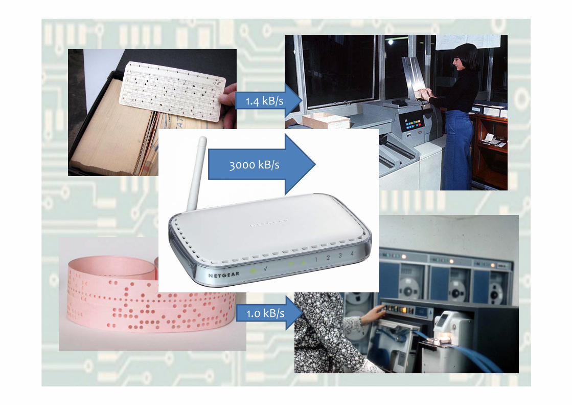
64 magnetic cores = 8 bytesSD card: 1 billion times more
Each magnetic core stores 1 bitHow many times more can the SD card store?

VNA Block Diagram
Main Memory
ALUProcessor
Data, Address and Control BusesWhat am I called?
I/O Devices

Main Memory Diagram
Main Memory
ALU
Data, Address and Control Buses
000
001
002
003
004
005
10010011
00000001
10001000
01100110
10101010
11111101 Latch
Tristate bufferWhat am I in decimal?And in hex?
VNA Block Diagram
Main Memory
ALUProcessor
Data, Address and Control Buses
I/O Devices

Processor Block Diagram
ALUControl
ALURegisters
Clock
Tristate buffer
What can you remember about the roles of ALU, control unit and registers?

Registers
• Registers are groups of electronic circuits called flip‐flops– They stick in one of two states, 1 or 0– By applying voltages to the inputs, they can be flipped into the other state under control of the clock signal
• These properties mean they can be used to store data (permanently, so long as the power is on)
• They are fast, but expensive to build compared to ‘normal’ memory
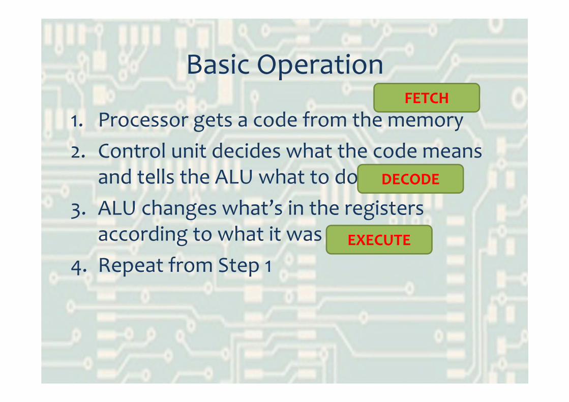
Basic Operation
1. Processor gets a code from the memory2. Control unit decides what the code means
and tells the ALU what to do3. ALU changes what’s in the registers
according to what it was told to do4. Repeat from Step 1
FETCH
DECODE
EXECUTE

Key Points for Exam• A von Neumann architecture computer:
– program and data stored together in memory– having a single CPU– which executes one instruction at a time– using fetch‐decode‐execute cycle
• A register is:– a temporary storage location– in the CPU (not in RAM)– usually having a specific purpose (RAM: general)– accessed very quickly (compared to RAM)
Lesson 1 – Outcomes
• Describe the characteristics of a von Neumann architecture computer
• Describe in outline the fetch‐decode‐executecycle
• Name the main elements within a CPU and describe what is meant by the term register

Lesson 2 – Outcomes
• Describe in detail the fetch‐decode‐executecycle including the use of specific registers
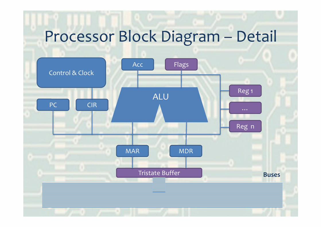
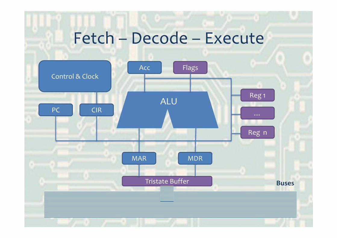
Processor Block Diagram – Detail
ALU
Acc Flags
CIR
MDR
PC
MAR
Reg 1
…
Reg n
BusesTristate Buffer
Control & Clock
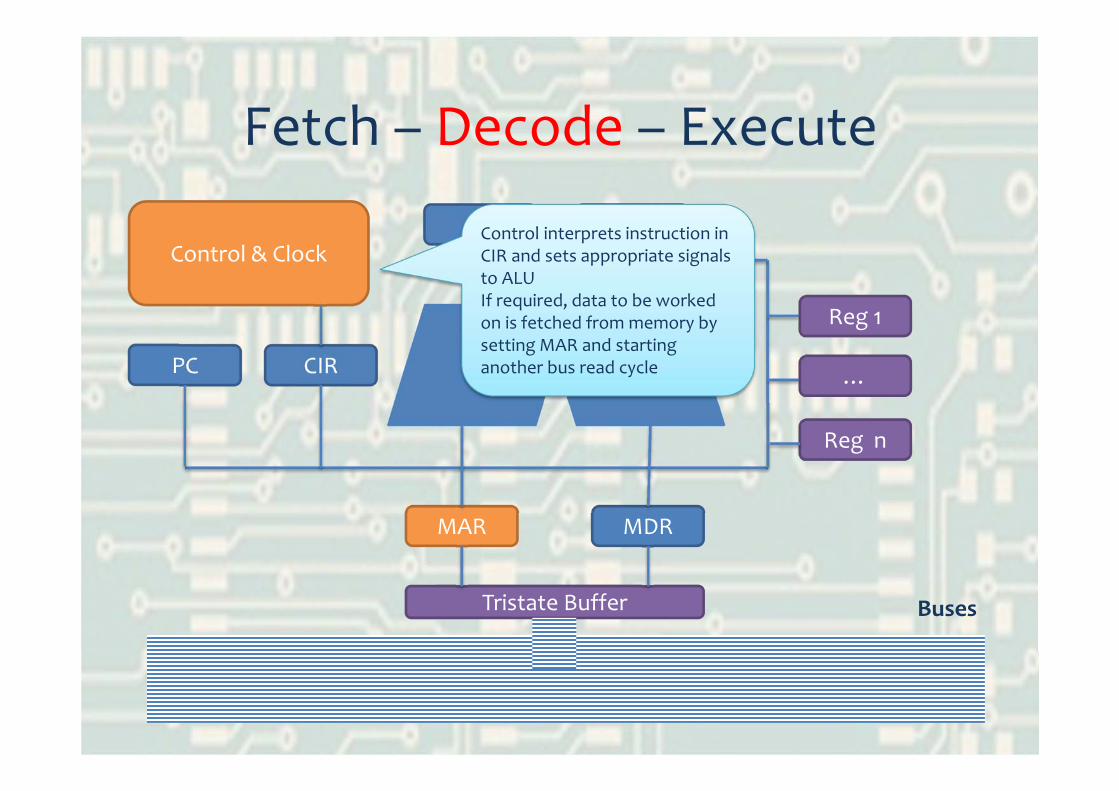
Fetch – Decode – Execute
ALU
Acc Flags
CIR
MDR
PC
MAR
Reg 1
…
Reg n
BusesTristate Buffer
Control & Clock

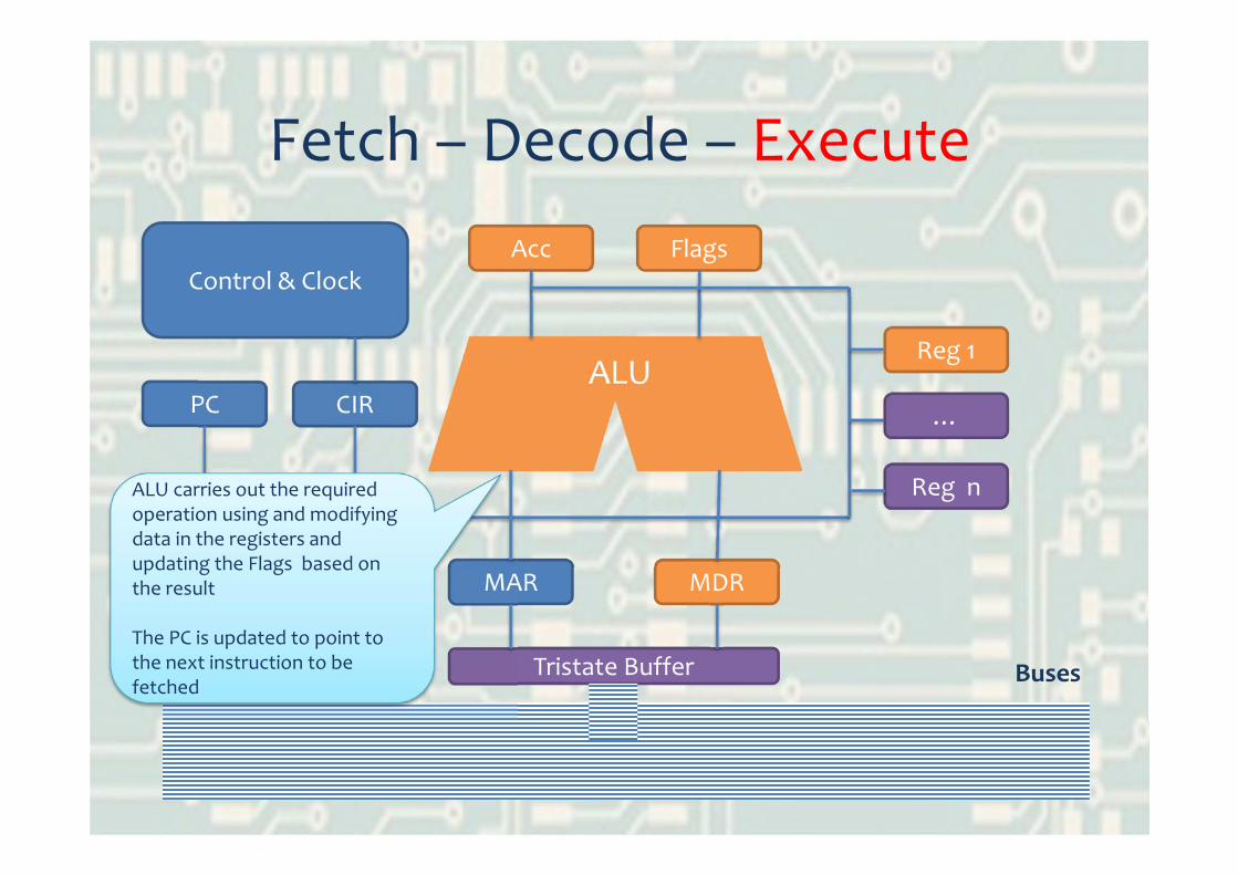
Fetch – Decode – Execute
ALU
Acc Flags
CIR
MDR
PC
MAR
Reg 1
…
Reg n
BusesTristate Buffer
Control & Clock
PC = 0Copied to MARBus read cycle initiated by control

Fetch – Decode – Execute
ALU
Acc Flags
CIR
MDR
PC
MAR
Reg 1
…
Reg n
BusesTristate Buffer
Memory responds with contents of location 0Latched from bus into MDR and copied to CIR
Control & Clock
Fetch – Decode – Execute
ALU
Acc Flags
CIR
MDR
PC
MAR
Reg 1
…
Reg n
BusesTristate Buffer
Control interprets instruction in CIR and sets appropriate signals to ALUIf required, data to be worked on is fetched from memory by setting MAR and starting another bus read cycle
Control & Clock
Fetch – Decode – Execute
ALU
Acc Flags
CIR
MDR
PC
MAR
Reg 1
…
Reg n
BusesTristate Buffer
ALU carries out the required operation using and modifying data in the registers and updating the Flags based on the result
The PC is updated to point to the next instruction to be fetched
Control & Clock

Key Points for Exam• The Program Counter (PC):
– holds address of next instruction to be fetched …– … in the fetch‐decode‐execute cycle;– is copied to MAR to fetch from main memory (and value returned to MDR is copied to CIR)
– is incremented after each instruction– unless jump/branch when CIR address copied to PC
• The accumulator:– all input/output data passes through it, because it– holds the data currently being worked on by ALU;– receives the results of ALU operations
Lesson 2 – Outcomes
• Describe in detail the fetch‐decode‐executecycle including the use of specific registers
Lesson 3 – Outcomes
• Describe what is meant by the terms machine code and assembly language
• Be able to write simple assembly language code fragments

Assembly Language
25 LDA 9 / load A from 926 SUB 1 / subtract from 127 STA 9 / store A back in 928 BNZ 25 / branch if not zero
What does this code fragment do?What would make it easier to program?
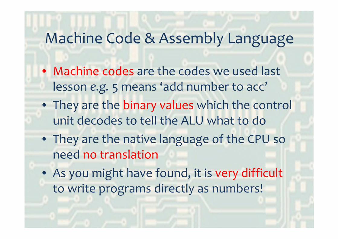
Machine Code & Assembly Language
• Machine codes are the codes we used last lesson e.g. 5 means ‘add number to acc’
• They are the binary values which the control unit decodes to tell the ALU what to do
• They are the native language of the CPU so need no translation
• As you might have found, it is very difficult to write programs directly as numbers!
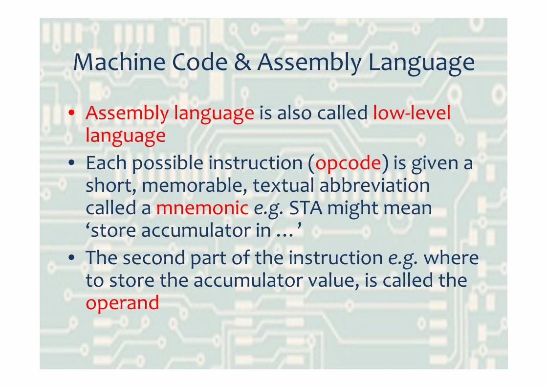
Machine Code & Assembly Language
• Assembly language is also called low‐level language
• Each possible instruction (opcode) is given a short, memorable, textual abbreviation called a mnemonic e.g. STA might mean ‘store accumulator in …’
• The second part of the instruction e.g. where to store the accumulator value, is called the operand

ExampleLDA 9 / Loads acc with the contents of memory 9ADD #7 / Adds the number 7 to the accumulatorSTA 5 / Stores acc result into memory 5
This is then translated by the assembler directly into machine code (which in this case might be) …
0011 10011001 01111000 0101
LDA is the mnemonic
5 is the operand
These are the corresponding machine codes

Concept Map – Answer
OpcodeOperand
Mnemonic
Machine Code
Assembler
is representedby …
acts on …
translatedby …
translatedinto …
Memorable text representation
of opcode
Instruction for ALU to perform
Data to perform operation on
Binary values for instructions
Translator

Exam Definitions• Opcode
– machine code instruction (binary number) e.g. 1001– tells ALU what to do with operand– represented by mnemonic
• Operand– is the (binary) value in the address field of an instruction– holds a data value or an address to be worked with
• Mnemonic– easily remembered– text representation of an opcode– letters stand for binary machine code– assembler translates mnemonic into machine code

Lesson 3 – Outcomes
• Describe what is meant by the terms machine code and assembly language
• Be able to write simple assembly language code fragments

Lesson 4 – Outcomes
• Explain what addressing modes are and how they can be used
• Write more complex assembly language code fragments
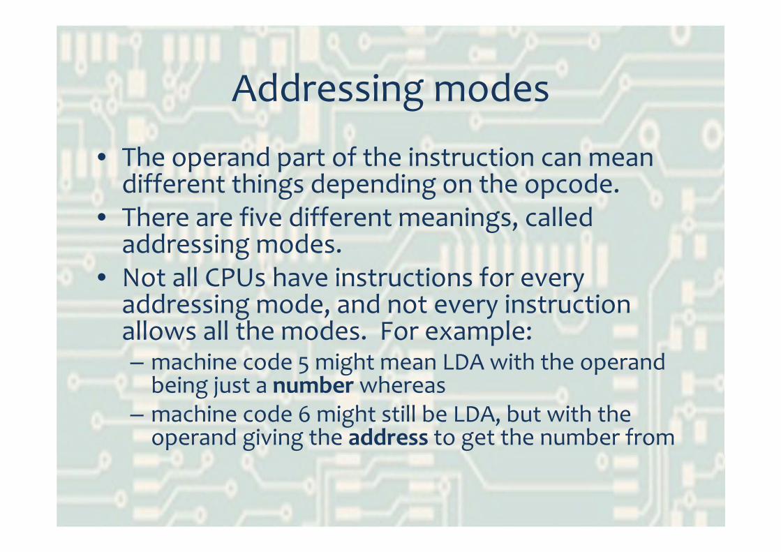
Addressing modes
• The operand part of the instruction can mean different things depending on the opcode.
• There are five different meanings, called addressing modes.
• Not all CPUs have instructions for every addressing mode, and not every instruction allows all the modes. For example:– machine code 5 might mean LDA with the operand being just a number whereas
– machine code 6 might still be LDA, but with the operand giving the address to get the number from

Addressing modes
Immediate Addressing• The operand is just a number, not an address e.g. LDA #5
Direct Addressing• The operand is the memory address where the number you want is stored e.g. LDA 12
Acc =0
LDA #5
Acc = 5
Acc =0
LDA 12
Acc = 7
12 7
I’m used when you just want a constant
I’m used when you know where the data is stored
… but I can only refer to limited
memory locations
0101 1001
1101 1100

Addressing modes
Indirect Addressing• The operand is a memory address. In that memory location is stored anotheraddress; it is this latter address which tells you where the data is stored e.g. LDA (12)
Acc =0
LDA (12)
Acc = 4
12 27
27 4
This address contains a pointer to the address of my data
Load from the address pointed to by address 12(and address 12 points to address 27)
Enables the same code to operate on different data (by adjusting the pointer)
Re‐usable code means functions or procedures

Addressing modes
Indexed Addressing• The operand is an address but instead of looking in thatmemory location, you look in the one X places further on, where X is the value in another register called an index register e.g. LDA 12,X
Acc =0, X=2
LDA 12,X
Acc = 6 12 8
13 7
14 6
15 5
I’m used when you have a table of data (array)
The index register is used like a loop variable so you can work on each data item in the array in turn

Addressing modes
Relative Addressing• The operand is a number which is added to the PC to find the address to be used e.g. BNE +3 means branch (if negative) three instructions further on from the current PC
BNE +3
LDA 12,X
ADD #5
STA 15
INX
I’m rarely used because you can use labels in assembly language
(symbolic addressing)
storeit
BNE storeit
Lesson 4 – Outcomes
• Explain what addressing modes are and how they can be used
• Write more complex assembly language code fragments
Lesson 5 – Outcomes
• Compare and contrast machine code, low‐level (assembly) language and high‐level languages
Comparison
• List the features of – Machine code– Assembly language– High level languages
• In what circumstances would you use each?

Machine Code
• Binary numbers• No translation• Very hard to write
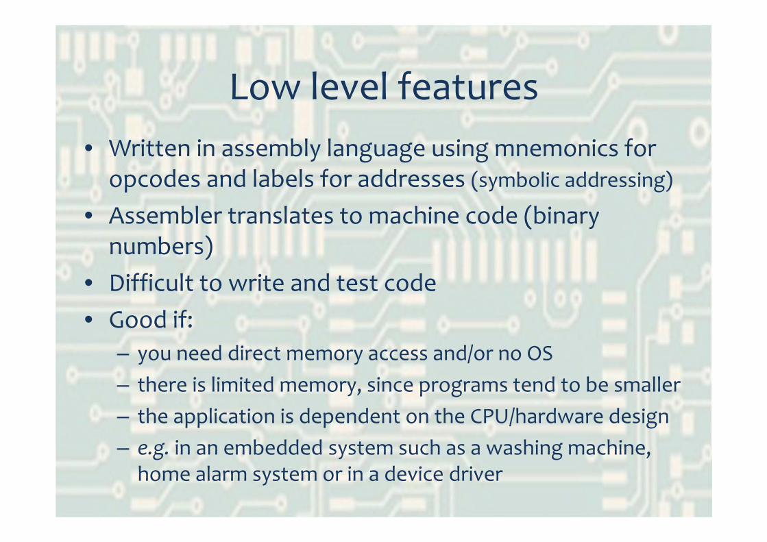
Low level features• Written in assembly language using mnemonics for
opcodes and labels for addresses (symbolic addressing)
• Assembler translates to machine code (binary numbers)
• Difficult to write and test code• Good if:
– you need direct memory access and/or no OS– there is limited memory, since programs tend to be smaller– the application is dependent on the CPU/hardware design– e.g. in an embedded system such as a washing machine,
home alarm system or in a device driver

High level features
• Like human language so easy to write• Can use maths functions like square root• Portable – can be compiled to run on different CPUs and machine architectures
• Can reuse the code for other applications• Can use existing library functions• Easier to test and debug

Lesson 5 – Outcomes
• Compare and contrast machine code, low‐level (assembly) language and high‐level languages

Lesson 6 – Outcomes
• Describe the trade‐offs that can be made in CPU design and define RISC
• Describe alternatives to von Neumann architecture including their advantages and disadvantages

Types of von Neumann CPUs
• CPUs are made from transistorsetched onto a silicon wafer
• A CPU that does complex tasksrequires a lot of circuitry andtherefore a large chip
• It sometimes pays to have a smaller ALU to make space on the chip for e.g.more registers
• This means the ALU can only perform a small number of simple operations
• Such a CPU is described as a RISC chip

Types of von Neumann CPUs
• RISC CPUs– have small instruction set– instructions all one size and take one clock cycle– often have higher clock rates– fewer addressing modes are supported– ALU performs only simple tasks– complex tasks need several instructions and so take many clock cycles to complete
– have many register banks as there is more chip area available

Types of von Neumann CPUs
• In contrast, CISC CPUs– have large instruction set– instructions of varying size– many addressing modes are supported– ALU performs complex tasks– single instructions can take many clock cycles to complete
– have fewer registers

Which is best?
• Nowadays the boundary is blurred– RISC chips have started including more instructions
– CISC chips can do some operations in a RISC‐like way
– Both have developed other CPU speed improvements like pipelining
• For exam, CISC slower at performing a specific operation ‘because it takes many clock cycles’
Not‐quite von Neumann architecture
• Co‐processors (e.g. for maths or graphics) operate at the same time as the main CPU
• Advantage: main processor can do something else while co‐processor works on a job, so programs run faster
• Disadvantage: have to program carefully to be able to make use of the time that is freed‐up (if it is possible)

Non von Neumann architectures
• Array processing (SIMD)– Many ALUs, all doing the same operation on multiple data values
– Extremely fast compared to von Neumann– But only good for certain jobs such as graphics, signal processing, weather forecasting …
• Parallel processing (MIMD)– Many CPUs, synchronised, each doing tasks that are parts of the whole job
– Complex operating system needed to divide the job between CPUs
– Really hard to write and compile programs
Lesson 6 – Outcomes
• Describe the trade‐offs that can be made in CPU design and define RISC
• Describe alternatives to von Neumann architecture including their advantages and disadvantages


![[ 1 2 ] Mnemonic Value and Historic P re s e rv a t i o n](https://img.pdfslide.us/doc/110x75/628099dc10a0c475f45b860a/-1-2-mnemonic-value-and-historic-p-re-s-e-rv-a-t-i-o-n.jpg)