Embed Size (px)
Citation preview

PARE PROJECT NO. 08216 .00
INSPECTION REPORT LEONARD’S WHARF
NEW BEDFORD WATERFRONT
FACILTIES INSPECTIONS NEW BEDFORD, MASSACHUSETTS
MARCH 2009

Leonard’s Wharf
Pare Corporation i
EXECUTIVE SUMMARY Leonard’s Wharf is a 1080 foot long filled pier structure retained by steel sheet piling, which was installed in 1974. The pier provides operational berthage for fishing vessels. Leonard’s Wharf was observed to be in generally poor to serious condition, with significant deficiencies. These deficiencies include severe corrosion of bolts fastening the tie back wale to the sheeting, and the presence of several large areas of subsidence at the eastern end of the wharf, corresponding with holes in the sheeting. Other deficiencies noted during the inspection include damages and deterioration of the timber fender system, cleats and timber curb. High priority remedial repairs include:
• A test pit investigation of the tie back system should be performed in order to verify the integrity of its components. Any of the internal components that are in similar deteriorated condition to the external hardware should be removed and replaced. The opinion of probable cost for this work is approximately $15,000.
• Replace the connection hardware to the lower wale. This will include excavation behind
the bulkhead to expose the internal wale along the length of the bulkhead and the removal and replacement of all fastening bolts. The opinion of probable construction cost for this work is approximately $204,000.
• Repair the holes observed in the steel sheetpile bulkhead. The opinion of probable
construction cost for this work is approximately $20,000. • Install concrete reinforcement of the sheeting near the head of the wharf. A six inch
thick reinforced concrete overlay, attached to the existing sheeting, will result in a cost of approximately $500 per lineal foot, resulting in an opinion of probable cost of $651,000 to reinforce the entire pier.
• Replace areas of the UHMW rub rail on the face of the timber wale. The opinion of
probable construction cost for this work is approximately $27,000. • Replace the corroded and damaged access ladders. The opinion of probable construction
cost for this work is approximately $22,000. Low priority remedial repairs include:
• Install cathodic protection along the steel sheetpile. Sacrificial anodes minimize
corrosion along the sheetpile by corroding at a higher rate than the metal sheetpile. The opinion of probable construction cost for this work is approximately $183,000.

Leonard’s Wharf
Pare Corporation ii
• Remove and replace damaged and worn areas of the timber wale. The opinion of probable construction cost for this work is approximately $46,500.

Leonard’s Wharf
Pare Corporation iii
TABLE OF CONTENTS
Page
SECTION 1 INTRODUCTION 1.1 Background and Objectives 1 1.2 Scope of Work 1
SECTION 2 DESCRIPTION OF SITE
2.1 Site Location 1 2.2 Facility Description 1
SECTION 3 EXISTING CONDITIONS
3.1 General 2 3.2 Steel Sheet Piling 2
3.3 Subsidence 3 3.4 Fender System 4 3.5 Appurtenances 4
SECTION 4 STRUCTURAL CONDITION ASSESSMENT
4.1 General 5 SECTION 5 RECOMMENDATIONS AND OPINION OF PROBABLE COST
5.1 Recommendations – General 6 5.2 High Priority 6 5.3 Lower Priority 7
TABLES: Table 3.1 – Underwater Readings Table 4.1 – Remaining Steel Sheetpile Thickness FIGURES: Figure 1 – Locus Plan Figure 2 – Existing Site Plan Figure 3 – Existing Sections and Details APPENDICES: Appendix A: Photographs Appendix B: Key Personnel Appendix C: Backup Data for Cost Estimates Appendix D: References Appendix E: Field Notes

Leonard’s Wharf
Pare Corporation 1
SECTION 1 INTRODUCTION 1.1 – Background and Objectives The New Bedford Harbor Development Commission (HDC) has retained Pare Corporation (PARE) and Childs Engineering Corporation (CEC) to perform an above and below water inspection, and to develop a report of existing conditions for Leonard’s Wharf in New Bedford, Massachusetts. Inspections were performed in accordance with the ASCE Manuals and Reports on Engineering Practice No. 101 – Underwater Investigations: Standard Practice Manual. The major objectives of the inspection report are to provide the HDC with an assessment of existing conditions at the facility, and to substantiate requests for funding for the maintenance and repair of the facility. 1.2 – Scope of Work The scope of this investigation is to provide an inspection and evaluation of the present condition of the pier and appurtenant structures, and to provide information that will assist in both prioritizing repair needs and planning/conducting maintenance and operation. The investigation is divided into three parts: 1) provide a description of the facility, including review of available reports, investigations, and data previously submitted to the owner pertaining to the wharf and appurtenant structures; 2) perform a visual inspection of the site above and below water; 3) prepare and submit a final report presenting the evaluation of the structure, including recommendations for remedial actions, and associated costs. SECTION 2 DESCRIPTION OF SITE 2.1 - Site Location Leonard’s Wharf is an approximate 1,058 foot long steel sheet pile bulkhead pier structure with solid fill. It is located south of Homer’s Wharf and north of the NSTAR storage tank and power facility along the New Bedford waterfront on Buzzard’s Bay as shown in Figure 1 – Locus Plan. 2.2 - Facility Description The original structure was an earth-filled stone wharf and was mainly used for the berthing of whaling vessels. Currently Leonard’s Wharf consists of a steel sheet pile bulkhead with solid fill and an asphalt deck providing dock space for modern fishing draggers and lobster boats. The steel sheet piling bulkhead is comprised of a PZ-38 section, installed in 1974. The sheeting is provided with interior double channel tieback wales, with tierods spaced at 6 foot intervals. The sheeting is fastened to the wales with two 1.5 inch diameter bolts at three foot intervals.

Leonard’s Wharf
Pare Corporation 2
The bulkhead is partially protected with 12 inch diameter timber fender piles at approximately 10 feet on center with 12 inch by 12 inch top and bottom timber wales. Most of the wharf, however, is protected with a 6 inch x 8 inch timber chock bolted to the top of the steetpile wall with a 2 inch x 5 inch UHMW rub rail bolted to the waterside face. Rubber tire fenders are attached to the face of the sheetpile spaced 12 feet on center. A C15 x 40 steel channel cap is located on top of the sheeting. An 8 inch x 12 inch timber curb is supported by 3 inch x 3 inch x 12 inch timber blocking spaced 36 inches on center on top of the cap channel. 32 inch long mooring cleats are spaced approximately 30 feet on center, and are bolted to a concrete block measuring 54 inches long by 16 inches wide and 12 inches high. The wharf is provided with an asphalt deck. According to available plans, the most recent repairs to the structure were completed in 1998. The repairs included but are not limited to: removal of the original timber fender system, installation of current rubber tire fenders, installation of fender pile clusters at the corners of the wharf, upgrading light posts and fixtures, installation of new safety ladders, patching holes in the sheetpile wall, and various repairs to the bituminous deck surface.
SECTION 3 EXISTING CONDITIONS 3.1 General The topside and underwater inspections of Leonard’s Wharf were performed on November 18, 2008. For reference purposes, a baseline was established along the top of the bulkhead during the inspection. Station 0+00 was located at the northwest corner of the bulkhead at its intersection with Homer’s Wharf and extended to station 10+58 at the southwestern end of the bulkhead at its intersection with the NSTAR property. Observations were made in relation to their location along the baseline as appropriate and as noted herein. Leonard’s Wharf was observed to have significant deficiencies, including several large areas of subsidence at the head of the wharf, corresponding with holes in the sheeting. Severe corrosion of bolts fastening the tie back wale to the sheeting was observed along the majority of the pier. Other deficiencies noted during the inspection include a broken portion of the timber curb from Station 6+37 to Station 6+45 and a broken cleat at Station 7+45. 3.2 Steel Sheet Piling The steel sheet piling system at Leonard’s Wharf is in poor condition. Major deficiencies observed include severely corroded connection hardware and two large corrosion holes in the sheeting. The bolts connecting the internal wale to the steel sheetpile between station 5+00 and 10+00 were observed to be severely corroded, with typically 70-100% section loss. The first corrosion hole is located at station 5+70, approximately 2 feet below Mean Low Water. It is 13 inches long by 5 inches wide and runs through both the flange and web. Fill material could be seen inside and is actively being flushed out from behind the sheet. The second large corrosion hole was observed approximately 1 foot below Mean Low Water at Station 6+71. The

Leonard’s Wharf
Pare Corporation 3
hole was located within the web of the steel sheetpile section and measured 1 foot long by 4 inches wide. Fill was observed escaping from this hole. It is understood that prior patching was performed at the head of the wharf in 1998. Typically, below the mean low water elevation the steel sheetpile bulkhead was observed to have a corrosion byproduct buildup of approximately 1/8 inch to ¼ inch. The byproduct was apparently getting thicker closer to the mudline. Small pits were observed on the steel and are approximately 1/16 inch to 1/8 inch deep. It was also noted that the bottom 3 rungs of the safety ladders are all severely corroded and are either completely missing or are unusable. During the inspection of the sheetpile, ultrasonic thickness (UT) and cathodic potential (CP) reading were taken. The readings were taken at the mudline, mean low water, and approximately halfway between the two. Conditions at this facility were found to be similar to adjacent facilities such as Fisherman’s Wharf, Steamship Pier, and Homer’s Wharf which all indicated potential readings between .3 and .5 volts. The following table illustrates the results.
Table 3.1 – Underwater Readings
STATION ELEVATION UT
Inner Flange UT Web
UT Outer Flange CP
0+00 Mud 0.460 0.265 0.420 0.398 Mid MLW 0.450 0.265 0.495 0.391
2+00 Mud 0.470 0.325 0.470 0.403 Mid 0.465 0.300 0.475 0.402 MLW 0.520 0.320 0.510 0.356
4+00 Mud 0.485 0.290 0.435 0.402 Mid 0.455 0.330 0.445 0.394 MLW 0.495 0.355 0.505 0.363
6+00 Mud 0.480 0.355 0.510 0.400 Mid 0.425 0.225 0.455 0.393
MLW 0.295 0.235 Too Heavy
Pitting 0.370 8+00 Mud 0.460 0.330 0.475 0.346
Mid 0.465 0.315 0.455 0.345 MLW 0.510 0.315 0.510 0.396
10+00 Mud 0.485 0.330 0.475 0.397 Mid 0.460 0.330 0.460 0.390
MLW 0.500 0.385 0.470 0.387 3.3 Subsidence Several areas of local subsidence were observed behind the bulkhead. Smaller depressions with water ponding were observed behind the bulkhead from Station 5+50 to Station 5+62 as shown in Photo No. 4 in Appendix A: Photographs. Two depressions were observed to have grass and weeds growing within the exposed fill material. The depression at Station 5+70 measured 24

Leonard’s Wharf
Pare Corporation 4
inch wide by 16 inches long by 4 inches deep, with the depression at Station 5+75 measuring 22 inches wide by 36 inches long by 15 inches deep. Large sinkholes were observed on both sides of the concrete block that supports the cleat at Station 5+72 as shown in Photos No. 5 and 6 in Appendix A: Photographs. A sinkhole observed at Station 6+70 was 12 inches wide by 30 inches long and was 16 inches deep as shown in Photo No. 12 in Appendix A: Photographs. These sinkholes correspond with corrosion holes in the sheetpile bulkhead that were observed during the underwater inspection. 3.4 Fender System The fender system at Leonard’s Wharf was observed to be in overall fair condition. Typical deficiencies were similar to the adjacent structures including damaged timber wale and missing or loose UHMW rub rails. The rubber tire fenders attached to the bulkhead face were observed to be in good condition. From Station 0+00 to Station 0+20, an older timber fender system protects the steel sheetpile bulkhead. It is comprised of 12 inch diameter timber fender piles at approximately 10 feet on center with 12 inch by 12 inch top and bottom timber wales. Only 1 fender pile was observed as part of this fender system and it was in overall fair condition with some signs of minimal rot. The top and bottom wales were observed to be in overall poor condition. They were predominantly hollow due to rot. At the time of the inspection, no vessels were observed docked against the older fender system. From Station 0+20 to the end of the new fender system at Station 10+58, the timber wales and UHMW rub rails were observed to be in overall poor condition. The rubber tire fenders were observed to be in overall good condition. Typical deficiencies include loose or missing UHMW rub rail and significant damage to the wales in several areas, as shown in Photographs No. 2, 3, 8, 9, and 13 in Appendix A: Photographs. Specific locations of damaged wales, loose rub rails, and missing rub rails are provided in Appendix E: Field Notes. 3.5 Appurtenances Galvanized steel ladders are located around the bulkhead to provide access to and from the deck to the water below. Overall the ladders were observed to be in poor condition. Some of the ladders are in good condition above mean high water, while others have been damaged during impact with vessels causing damage to the rungs and buckling of members. All of the ladders are corroded below mean high water rendering them useless during times of low water. Life rings were observed along the bulkhead at several locations, attached with a 4 inch x 4 inch post notched into the timber curb.

Leonard’s Wharf
Pare Corporation 5
4.0 – Structural Condition Assessment 4.1 General Based on the observations obtained from the site inspections, the following provides our assessment of the various structural components. Existing structural condition determinations were based on visual and tactile observations only, and were limited to accessible and visible portions of the structures. Based upon the visual inspection of topside and underwater structures along with the observed thickness readings, Leonard’s Wharf is in generally poor to serious condition and is in need of rehabilitation. The severely corroded connection hardware reduces the structural capacity of the bulkhead. This condition needs to be addressed without delay. It is recommended that the allowable loading on the head of the pier be restricted to light vehicular traffic, in an effort not to overstress the deteriorated fasteners. It is also recommended that this area be further inspected, with test pits carried out, to determine the degree of corrosion of the interior wale and to enable the design of repairs to the tieback system. While the majority of the steel sheet piling was observed to exhibit typical section loss for steel of this age in a marine environment, the head of the pier has several large holes in the steel sheetpile bulkhead near the head of the pier require rehabilitation. If not addressed quickly, the fill materials will continue to wash out through the hole, creating sinkholes in the pier deck above. The sheeting at the head of the pier has advanced corrosion as compared to the rest of the facility, and should be reinforced to continue to provide service. The corners of the sheeting at the head of the pier have been previously repaired in 1998. The following table represents the thickness readings and estimated remaining section of the steel sheetpile.
Table 4.1 – Remaining Steel Sheetpile Thickness Nominal Flange Thickness = 0.500” Nominal Web Thickness =0.375”
Inner Flange Percent Remaining Web Percent Remaining
Outer Flange Percent Remaining
0.460 92.0 0.265 70.7 0.420 84.0 0.450 90.0 0.265 70.7 0.495 99.0 0.470 94.0 0.325 86.7 0.470 94.0 0.465 93.0 0.300 80.0 0.475 95.0 0.520 104.0 0.320 85.3 0.510 102.0 0.485 97.0 0.290 77.3 0.435 87.0 0.455 91.0 0.330 88.0 0.445 89.0 0.495 99.0 0.355 94.7 0.505 101.0 0.480 96.0 0.355 94.7 0.510 102.0 0.425 85.0 0.225 60.0 0.455 91.0 0.295 59.0 0.235 62.7 0.475 95.0 0.460 92.0 0.330 88.0 0.455 91.0 0.465 93.0 0.315 84.0 0.510 102.0

Leonard’s Wharf
Pare Corporation 6
0.510 102.0 0.315 84.0 0.475 95.0 0.485 97.0 0.330 88.0 0.460 92.0 0.460 92.0 0.330 88.0 0.470 94.0 0.500 100.0 0.385 102.7
Typical UT thickness readings on the web indicated average section loss of 17.3% with a maximum reading of 40.0% loss at Station 6+00 midway between mean low water and the mudline. Average section loss on the flanges was 6.9% with a maximum reading of 41.0% section loss on the inner flange at Station 6+00 at the mudline. Using the average section loss and estimating the construction date to 1974, average corrosion rates indicate a loss of section of approximately 0.009 inches per year. SECTION 5 RECOMMENDATIONS AND OPINION OF PROBABLE COST 5.1 – Recommendations - General Based on conditions observed during the inspections, and the corresponding assessments of the existing structures, the following recommendations are provided for the repair and rehabilitation of these structures. Opinions of probable cost were generated based upon current industry unit prices for similar work. Breakdowns of cost are provided in the Appendix. The cost opinions provided are for construction only and do not include allowances for engineering, permitting, or construction administration. A 20 percent contingency has been included with these costs. The opinions shown herein are based on a limited investigation and are provided for general information only. This should not be considered an engineer’s estimate, as final design has not been performed, and actual construction costs may be somewhat less or considerably more than indicated, due to fluctuations in the market. In general, the overall condition of Leonard’s Wharf is critical, with severely corroded tieback connection hardware, and holes in the steel sheet piling. The repairs presented below must be implemented to maintain the integrity of the structure. If deferred these maintenance items could develop into larger safety concerns and deficiencies that are more costly to address. 5.2 – High Priority The following items are considered to have a High Priority, as they affect the usability and safety of the structure:
A test pit investigation of the tie back system should be performed in order to verify the integrity of its components. Any of the internal components that are in similar to the external hardware should be removed and replaced. The opinion of probable construction cost for this work is approximately $15,000.

Leonard’s Wharf
Pare Corporation 7
Replace the connection hardware to the lower wale. This will include excavation behind the bulkhead to expose the internal wale along the length of the bulkhead and the removal and replacement of all fastening bolts. The opinion of probable construction cost for this work is approximately $204,000. Repair the holes observed in the steel sheetpile bulkhead. Similar conditions at nearby structures have been repaired using a steel plate patch welded to the bulkhead face. The opinion of probable construction cost for this work is approximately $20,000. Install reinforcement of the sheeting near the head of the wharf. While the limits of the reinforcement can be determined with a more thorough investigation, it has been assumed that the entire face of the pier will need reinforcement. A six inch thick reinforced concrete overlay, attached to the existing sheeting, will result in a cost of approximately $500 per lineal foot, resulting in an opinion of probable cost of $651,000 to reinforce the entire pier.
Replace the UHMW rub rail on the face of the timber wale. Some of the existing UHMW is in good condition and may be reused. If the rub rail is not replaced and refastened, replacement of the timber wale will also become a high priority. The opinion of probable construction cost for this work is approximately $27,000. Replace the corroded and damaged access ladders. The ladders are built into the fender system and therefore incur similar damage from docking vessels. The opinion of probable construction cost for this work is approximately $22,000.
Install cathodic protection along the steel sheetpile. Sacrificial anodes minimize corrosion along the sheetpile by corroding at a higher rate than the metal sheetpile. The opinion of probable construction cost for this work is approximately $183,000.
5.3 – Lower Priority The following items are considered to have a Lower Priority, as they presently do not affect the usability and safety of the structure, but will need to be addressed in approximately 5 to 10 years. Remove and replace damaged and worn timber wale. Currently the UHMW rub rail protects the wale, which will extend the life of the timber; however, if the current condition of the rub rail is not addressed, the timber wale may be damaged to the extent that it will be moved to the list of high priority repairs. The opinion of probable construction cost for this work is approximately $46,500.

Figures Leonard’s Wharf
New Bedford, Massachusetts

FIGURE 1
LOCUS PLAN
LEONARD’S WHARFNEW BEDFORD, MASSACHUSETTS
NEW BEDFORD HARBOR DEVELOPMENT COMMISSIONNEW BEDFORD WATERFRONT FACILITY INSPECTIONS
NOVEMBER 2008
PROJECT LOCATION


Appendix A Photographs
Leonard’s Wharf New Bedford, Massachusetts

Leonard’s Wharf, New Bedford, MA
Inspection Date: November 18, 2008New Bedford Waterfront Facilities InspectionsInspection Photographs
Photo No. 1: Overview of the Leonard’s Wharf bulkhead with docked vessel from Station 0+00 looking east.
Photo No. 2: Overview of the timber curb. Note the loose UHMW rub rail along the timber wale.

Leonard’s Wharf, New Bedford, MA
Inspection Date: November 18, 2008New Bedford Waterfront Facilities InspectionsInspection Photographs
Photo No. 3: Loose UHMW held to fender system with nylon rope.
Photo No. 4: Subsidence with ponded water from Station 5+50 to Station 5+62.

Leonard’s Wharf, New Bedford, MA
Inspection Date: November 18, 2008New Bedford Waterfront Facilities InspectionsInspection Photographs
Photo No. 5: Area of subsidence (4” deep) at Station 5+70.
Photo No. 6: Area of subsidence (15” deep) at Station 5+75.

Leonard’s Wharf, New Bedford, MA
Inspection Date: November 18, 2008New Bedford Waterfront Facilities InspectionsInspection Photographs
Photo No. 7: Corrosion hole in the steel sheetpile at Station 5+70. (Photo by Childs Engineering Corp).
Photo No. 8: Corrosion hole in the steel sheetpile at Station 5+70. (Photo by Childs Engineering Corp).

Leonard’s Wharf, New Bedford, MA
Inspection Date: November 18, 2008New Bedford Waterfront Facilities InspectionsInspection Photographs
Photo No. 10: Damaged fender system from Station 6+00 to Station 6+60.
Photo No. 9: Damaged timber wale near Station 5+90.

Leonard’s Wharf, New Bedford, MA
Inspection Date: November 18, 2008New Bedford Waterfront Facilities InspectionsInspection Photographs
Photo No. 11: Broken and missing timber curb from Station 6+37 to Station 6+45.
Photo No. 12: Area of subsidence (16” deep) at Station 6+70.

Leonard’s Wharf, New Bedford, MA
Inspection Date: November 18, 2008New Bedford Waterfront Facilities InspectionsInspection Photographs
Photo No. 13: Corrosion hole in the steel sheetpile at Station 6+71. (Photo by Childs Engineering Corp.)
Photo No. 14: Corrosion hole in the steel sheetpile at Station 6+71. (Photo by Childs Engineering Corp.)

Leonard’s Wharf, New Bedford, MA
Inspection Date: November 18, 2008New Bedford Waterfront Facilities InspectionsInspection Photographs
Photo No. 15: Loose UHMW from Station 6+80 to approximately Station 7+19.
Photo No. 16: Broken cleat at Station 7+45.

Leonard’s Wharf, New Bedford, MA
Inspection Date: November 18, 2008New Bedford Waterfront Facilities InspectionsInspection Photographs
Photo No. 17: Buckled galvanized ladder at Station 7+89.
Photo No. 18: Overview of the bituminous deck.

Leonard’s Wharf, New Bedford, MA
Inspection Date: November 18, 2008New Bedford Waterfront Facilities InspectionsInspection Photographs
Photo No. 19: Overview of the pier from Station 10+63 looking East.
Photo No. 20: Typical view of the steel sheetpile bulkhead, rubber tire fender, loose UHMW rub rail, and damaged wale.

Leonard’s Wharf, New Bedford, MA
Inspection Date: November 18, 2008New Bedford Waterfront Facilities InspectionsInspection Photographs
Photo No. 21: Typical underwater hardware. (Photo by Childs Engineering Corp.)
Photo No. 22: Typical underwater view of the steel sheetpile. (Photo by Childs Engineering Corp.)
Leonard’s Wharf, New Bedford, MA
Inspection Date: November 18, 2008New Bedford Waterfront Facilities InspectionsInspection Photographs
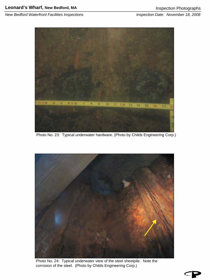
Photo No. 23: Typical underwater hardware. (Photo by Childs Engineering Corp.)
Photo No. 24: Typical underwater view of the steel sheetpile. Note the corrosion of the steel. (Photo by Childs Engineering Corp.)

Appendix B Key Personnel
Leonard’s Wharf New Bedford, Massachusetts

Coal Pocket Pier
Pare Corporation
KEY PERSONNEL
The following personnel were involved with this project including but not limited to the topside and underwater inspections and the preparation of this report: Name Employer Responsibilities Karl Hammond, P.E. PARE Corporation Project Manager, Lead Engineer Ernest O. Rabideau, Jr., P.E. PARE Corporation Project Reviewer Matt Bellisle, P.E. PARE Corporation Principal in Charge Craig Sams, P.E. Childs Engineering Corporation Principal in Charge Robert Garrity, P.E. Childs Engineering Corporation Project Engineer for Underwater Inspections Kevin Champagne, P.E. PARE Corporation Support Engineer Richard Fitzgerald, P.E. Childs Engineering Corporation Underwater Inspection Team Charlie Marshall Roberts Childs Engineering Corporation Underwater Inspection Team Robert Welch Childs Engineering Corporation Underwater Inspection Team Phil Iantosca Childs Engineering Corporation Underwater Inspection Team Nicholas B. Sarata Childs Engineering Corporation Underwater Inspection Team Ryan McCoy PARE Corporation Topside Inspection Briscoe B. Lang PARE Corporation Permitting Services

Appendix C Backup Data for Cost Estimates
Leonard’s Wharf New Bedford, Massachusetts

LEONARD'S WHARFOPINION OF PROBABLE CONSTRUCTION COST
February, 2009
QTY UNIT UNIT PRICE TOTALHigh Priority Repairs1. Mobilization/Demobilization 1 LS 25,000.00$ 25,000.00$ 2. Demolition and Removal 1 LS 25,000.00$ 25,000.00$ 3. Tieback Test Pits 1 LS 15,000.00$ 15,000.00$ 4. Tieback Connection Repair 4a. Tieback Excavation/Backfill 3,805 CY 30.00$ 114,150.00$ 4b. New Tieback Hardware 30 DAY 3,000.00$ 90,000.00$ 5. Sheetpile Patching 2 EACH 10,000.00$ 20,000.00$ 6. UHMW Rub Rail 1,070 LF 30.00$ 32,100.00$ 7. Ladders 11 EACH 2,000.00$ 22,000.00$ 8. Cathodic Protection 73,200 LB 2.50$ 183,000.00$
Subtotal 526,250.00$ Contingency 20% 105,250.00$ Total 631,500.00$
Low Priority Repairs1. Timber Wale 7 MBF 6,500.00$ 46,410.00$
Subtotal 46,410.00$ Contingency 20% 9,282.00$ Total 55,692.00$
WHARF REHABILITATION
PARE Project No.: 08216.00


Appendix D References
Leonard’s Wharf New Bedford, Massachusetts

Coal Pocket Pier
Pare Corporation
REFERENCES
The following references were utilized during the preparation of this report and the development of the recommendations presented herein: 1. “About the Port – Key Locations”, New Bedford Harbor Development Commission,
http://www.newbedford-ma.gov/PortofNewBedford/AboutPort/KeyLocations.html 2. “Maritime History of Massachusetts – Merrill’s Wharf Historic District”, National Park
Service, http://www.nps.gov/history/NR/travel/maritime/mer.htm. 3. Construction Drawings “Proposed Repairs and Improvements to Wharves and Piers in
New Bedford and Fairhaven, MA”, Tibbetts Engineering Corp., January 23, 1998 (Revised March 20, 1998).
4. Construction Drawings “Construction of Steamship Pier and Coalpocket Pier”, Tibbetts
Engineering Corp., June 1977 (Revised November 1977).

Appendix E Field Notes
Leonard’s Wharf New Bedford, Massachusetts