Embed Size (px)
Citation preview
Lensless Diffractive Imaging Using Tabletop Coherent High-Harmonic Soft-X-Ray Beams
Richard L. Sandberg,* Ariel Paul, Daisy A. Raymondson, Steffen Hadrich, David M. Gaudiosi, Jim Holtsnider,Ra’anan I. Tobey, Oren Cohen, Margaret M. Murnane, and Henry C. Kapteyn
JILA and Department of Physics, University of Colorado and NSF Engineering Research Center in Extreme UltravioletScience and Technology, Boulder, Colorado 80309, USA
Changyong Song and Jianwei MiaoDepartment of Physics and Astronomy, University of California, Los Angeles, California 90095, USA
Yanwei Liu and Farhad SalmassiCenter for X-Ray Optics, Lawrence Berkeley National Laboratory, Berkeley, California 94720, USA
(Received 18 April 2007; published 29 August 2007)
We present the first experimental demonstration of lensless diffractive imaging using coherent softx rays generated by a tabletop soft-x-ray source. A 29 nm high harmonic beam illuminates an object, andthe subsequent diffraction is collected on an x-ray CCD camera. High dynamic range diffraction patternsare obtained by taking multiple exposures while blocking small-angle diffraction using beam blocks ofvarying size. These patterns reconstruct to images with 214 nm resolution. This work demonstrates apractical tabletop lensless microscope that promises to find applications in materials science, nanoscience,and biology.
DOI: 10.1103/PhysRevLett.99.098103 PACS numbers: 87.59.�e, 61.10.�i, 41.50.+h, 42.65.�k
Microscopy has been a critical enabling technology forunderstanding materials and biological systems since itsinvention. Using innovative imaging and labeling tech-niques, visible light microscopes can image living cellswith a resolution as high as 200 nm [1]. However, thisresolution is fundamentally limited by the wavelength oflight in the visible to near-UV range. To further increaseresolution, the much shorter wavelength of moderate-energy electrons can be used, and atomic level resolutionhas been demonstrated in electron microscopy [2].However, electron microscopes are limited by the mean-free-path of the charged particles, and therefore this tech-nique is restricted to imaging thin samples, typically<500 nm. Many biological specimens, as well as samplesof interest for materials science, are too thick for electronmicroscopy. Furthermore, low contrast in electron micros-copy also requires sophisticated labeling techniques. Thus,new techniques for nanomicroscopy are of great interest.
One of the most promising alternative approaches forhigh-resolution imaging of thicker samples is to use shorterwavelength light, in the extreme ultraviolet (EUV) or soft-x-ray (SXR) regions of the spectrum [3]. EUVor SXR lightcan be used for nondestructive imaging applications re-quiring high resolution in thick samples [4]. Furthermore,numerous core-level absorption edges and widely varyingelemental absorption cross sections provide excellent in-herent image contrast, particularly for biological imagingin the ‘‘water window’’ (300 eV–500 eV) region of thespectrum, or for magnetic domain imaging around 800 eV[3–6]. Successful soft-x-ray imaging techniques use dif-fractive or reflective optics such as Fresnel zone plates ormultilayer mirrors, since the very strong absorption by
matter and low index contrast of materials at short wave-lengths precludes the use of refractive optics. Zone-plateimaging has been demonstrated at resolutions as highas 15 nm using state-of-the-art diffractive optics at syn-chrotron sources [7], while zone-plate imaging with tab-letop high harmonic sources can achieve resolutions of� 200 nm [8]. Zone plates require very careful manufac-turing, with feature sizes equal to the desired resolution,and dimensional tolerances several times smaller. Fur-thermore, microscopes based on zone-plate optics have arelatively short depth of field.
Lensless imaging is a relatively new coherent imagingtechnique that is complementary to zone-plate imaging [9–13]. This technique requires spatially coherent beams andeliminates imaging elements in the optical system byreplacing them with a computerized phase retrieval algo-rithm. By obviating the need for an imaging system, lens-less imaging is well-suited to x rays, and it was firstdemonstrated in 1999 using spatially filtered light from asynchrotron source [9]. In lensless imaging, the x-ray beamilluminates an object, and the scatter pattern (diffractedlight) from the object is collected on an x-ray CCD camera.For this technique to work, the diffraction pattern must beoversampled, i.e., the diffraction peaks coming from thehighest spatial frequency of interest must be sampled at ahigher rate than the Nyquist criterion [14]. If a sharpdiffraction pattern has been obtained and the oversamplingrequirement is met, the image can be reconstructed usingiterative algorithms that retrieve both its amplitude andphase [15].
Given the need for coherent illumination, most small-scale EUV=SXR sources are not suitable for lensless imag-
PRL 99, 098103 (2007) P H Y S I C A L R E V I E W L E T T E R S week ending31 AUGUST 2007
0031-9007=07=99(9)=098103(4) 098103-1 © 2007 The American Physical Society
ing. Thus, to date, lensless imaging has been the soledomain of large x-ray facilities such as synchrotrons orfree-electron lasers, where the bright beams can be madecoherent by spatial filtering. Recently, the first lenslessimaging using a soft-x-ray free-electron laser facility at32 nm was demonstrated. In that work, the high per-pulseenergy of the FEL allowed single shot diffraction data to becollected [16]. However, because the sample was destroyedin the process, multiple exposures to increase the dynamicrange of the data were not possible, and low spatial fre-quency information about the sample was missing.
High harmonic generation in gas-filled waveguide gen-erates spatially coherent EUV beams and is ideally suitedfor lensless imaging [17,18]. This light source has alreadybeen used for Gabor holography with resolution <10 �m[17]. Although Gabor holography and lensless imaging areboth coherent imaging techniques, geometric and fluxconsiderations make lensless imaging better suited tohigh resolution imaging in a compact geometry. Here, wepresent the first experimental demonstration of lenslessimaging using a tabletop source of coherent soft x rays.By taking multiple exposures while blocking small-anglescattered light using beam blocks of varying size, weobtain very high dynamic range diffraction patterns whichsuccessfully reconstruct to images with resolution near200 nm. Moreover, no low spatial frequency informationis missing from the reconstructions. This work thus dem-onstrates that lensless diffractive imaging can be success-fully implemented using tabletop light sources, with broadpotential application in nanoimaging and biologicalimaging.
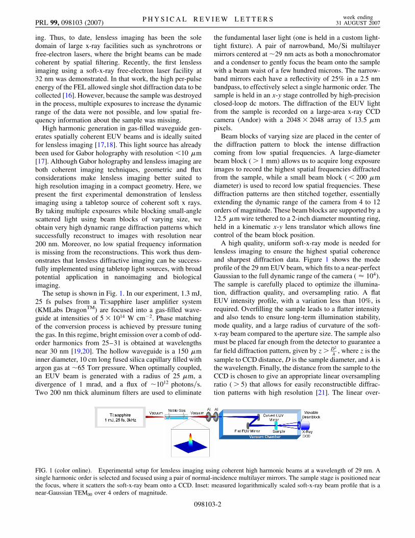
The setup is shown in Fig. 1. In our experiment, 1.3 mJ,25 fs pulses from a Ti:sapphire laser amplifier system(KMLabs DragonTM) are focused into a gas-filled wave-guide at intensities of 5� 1014 W cm�2. Phase matchingof the conversion process is achieved by pressure tuningthe gas. In this regime, bright emission over a comb of odd-order harmonics from 25–31 is obtained at wavelengthsnear 30 nm [19,20]. The hollow waveguide is a 150 �minner diameter, 10 cm long fused silica capillary filled withargon gas at �65 Torr pressure. When optimally coupled,an EUV beam is generated with a radius of 25 �m, adivergence of 1 mrad, and a flux of �1012 photons=s.Two 200 nm thick aluminum filters are used to eliminate
the fundamental laser light (one is held in a custom light-tight fixture). A pair of narrowband, Mo=Si multilayermirrors centered at�29 nm acts as both a monochromatorand a condenser to gently focus the beam onto the samplewith a beam waist of a few hundred microns. The narrow-band mirrors each have a reflectivity of 25% in a 2.5 nmbandpass, to effectively select a single harmonic order. Thesample is held in an x-y stage controlled by high-precisionclosed-loop dc motors. The diffraction of the EUV lightfrom the sample is recorded on a large-area x-ray CCDcamera (Andor) with a 2048� 2048 array of 13:5 �mpixels.
Beam blocks of varying size are placed in the center ofthe diffraction pattern to block the intense diffractioncoming from low spatial frequencies. A large-diameterbeam block (> 1 mm) allows us to acquire long exposureimages to record the highest spatial frequencies diffractedfrom the sample, while a small beam block (< 200 �mdiameter) is used to record low spatial frequencies. Thesediffraction patterns are then stitched together, essentiallyextending the dynamic range of the camera from 4 to 12orders of magnitude. These beam blocks are supported by a12:5 �m wire tethered to a 2-inch diameter mounting ring,held in a kinematic x-y lens translator which allows finecontrol of the beam block position.
A high quality, uniform soft-x-ray mode is needed forlensless imaging to ensure the highest spatial coherenceand sharpest diffraction data. Figure 1 shows the modeprofile of the 29 nm EUV beam, which fits to a near-perfectGaussian to the full dynamic range of the camera ( � 104).The sample is carefully placed to optimize the illumina-tion, diffraction quality, and oversampling ratio. A flatEUV intensity profile, with a variation less than 10%, isrequired. Overfilling the sample leads to a flatter intensityand also tends to ensure long-term illumination stability,mode quality, and a large radius of curvature of the soft-x-ray beam compared to the aperture size. The sample alsomust be placed far enough from the detector to guarantee afar field diffraction pattern, given by z > D2
� , where z is thesample to CCD distance,D is the sample diameter, and � isthe wavelength. Finally, the distance from the sample to theCCD is chosen to give an appropriate linear oversamplingratio (> 5) that allows for easily reconstructible diffrac-tion patterns with high resolution [21]. The linear over-
FIG. 1 (color online). Experimental setup for lensless imaging using coherent high harmonic beams at a wavelength of 29 nm. Asingle harmonic order is selected and focused using a pair of normal-incidence multilayer mirrors. The sample stage is positioned nearthe focus, where it scatters the soft-x-ray beam onto a CCD. Inset: measured logarithmically scaled soft-x-ray beam profile that is anear-Gaussian TEM00 over 4 orders of magnitude.
PRL 99, 098103 (2007) P H Y S I C A L R E V I E W L E T T E R S week ending31 AUGUST 2007
098103-2
sampling ratio relates the smallest diffraction patternspeckles to CCD pixels, and it is given by O � z�
pD , wherep is the pixel size of the CCD camera. For the two imagesdescribed here, the linear oversampling ratios were�10. Inthe reconstructed image, each image pixel (not to be con-fused with a CCD pixel) corresponds to a size d given byd � z�
pN , where N is the number of pixels. This image pixelsize is thus the ultimate resolution for any given geometry.Another limit on the resolution, r, of the reconstruction isthe spectral bandwidth, �=�� of the source, where r �OD�=�� [21]. By inspecting the speckle pattern at high scat-tering angles, we estimate a spectral bandwidth >200.
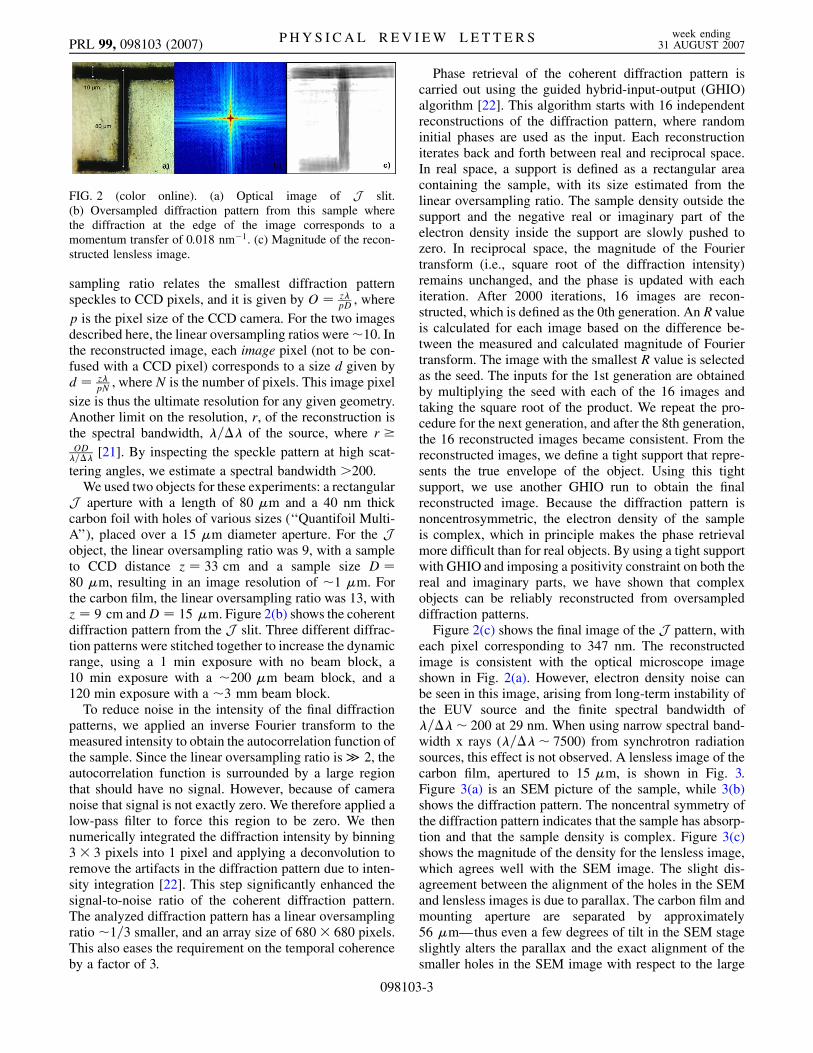
We used two objects for these experiments: a rectangularJ aperture with a length of 80 �m and a 40 nm thickcarbon foil with holes of various sizes (‘‘Quantifoil Multi-A’’), placed over a 15 �m diameter aperture. For the Jobject, the linear oversampling ratio was 9, with a sampleto CCD distance z � 33 cm and a sample size D �80 �m, resulting in an image resolution of �1 �m. Forthe carbon film, the linear oversampling ratio was 13, withz � 9 cm andD � 15 �m. Figure 2(b) shows the coherentdiffraction pattern from the J slit. Three different diffrac-tion patterns were stitched together to increase the dynamicrange, using a 1 min exposure with no beam block, a10 min exposure with a �200 �m beam block, and a120 min exposure with a �3 mm beam block.
To reduce noise in the intensity of the final diffractionpatterns, we applied an inverse Fourier transform to themeasured intensity to obtain the autocorrelation function ofthe sample. Since the linear oversampling ratio is� 2, theautocorrelation function is surrounded by a large regionthat should have no signal. However, because of cameranoise that signal is not exactly zero. We therefore applied alow-pass filter to force this region to be zero. We thennumerically integrated the diffraction intensity by binning3� 3 pixels into 1 pixel and applying a deconvolution toremove the artifacts in the diffraction pattern due to inten-sity integration [22]. This step significantly enhanced thesignal-to-noise ratio of the coherent diffraction pattern.The analyzed diffraction pattern has a linear oversamplingratio �1=3 smaller, and an array size of 680� 680 pixels.This also eases the requirement on the temporal coherenceby a factor of 3.
Phase retrieval of the coherent diffraction pattern iscarried out using the guided hybrid-input-output (GHIO)algorithm [22]. This algorithm starts with 16 independentreconstructions of the diffraction pattern, where randominitial phases are used as the input. Each reconstructioniterates back and forth between real and reciprocal space.In real space, a support is defined as a rectangular areacontaining the sample, with its size estimated from thelinear oversampling ratio. The sample density outside thesupport and the negative real or imaginary part of theelectron density inside the support are slowly pushed tozero. In reciprocal space, the magnitude of the Fouriertransform (i.e., square root of the diffraction intensity)remains unchanged, and the phase is updated with eachiteration. After 2000 iterations, 16 images are recon-structed, which is defined as the 0th generation. An R valueis calculated for each image based on the difference be-tween the measured and calculated magnitude of Fouriertransform. The image with the smallest R value is selectedas the seed. The inputs for the 1st generation are obtainedby multiplying the seed with each of the 16 images andtaking the square root of the product. We repeat the pro-cedure for the next generation, and after the 8th generation,the 16 reconstructed images became consistent. From thereconstructed images, we define a tight support that repre-sents the true envelope of the object. Using this tightsupport, we use another GHIO run to obtain the finalreconstructed image. Because the diffraction pattern isnoncentrosymmetric, the electron density of the sampleis complex, which in principle makes the phase retrievalmore difficult than for real objects. By using a tight supportwith GHIO and imposing a positivity constraint on both thereal and imaginary parts, we have shown that complexobjects can be reliably reconstructed from oversampleddiffraction patterns.
Figure 2(c) shows the final image of the J pattern, witheach pixel corresponding to 347 nm. The reconstructedimage is consistent with the optical microscope imageshown in Fig. 2(a). However, electron density noise canbe seen in this image, arising from long-term instability ofthe EUV source and the finite spectral bandwidth of�=��� 200 at 29 nm. When using narrow spectral band-width x rays (�=��� 7500) from synchrotron radiationsources, this effect is not observed. A lensless image of thecarbon film, apertured to 15 �m, is shown in Fig. 3.Figure 3(a) is an SEM picture of the sample, while 3(b)shows the diffraction pattern. The noncentral symmetry ofthe diffraction pattern indicates that the sample has absorp-tion and that the sample density is complex. Figure 3(c)shows the magnitude of the density for the lensless image,which agrees well with the SEM image. The slight dis-agreement between the alignment of the holes in the SEMand lensless images is due to parallax. The carbon film andmounting aperture are separated by approximately56 �m—thus even a few degrees of tilt in the SEM stageslightly alters the parallax and the exact alignment of thesmaller holes in the SEM image with respect to the large
FIG. 2 (color online). (a) Optical image of J slit.(b) Oversampled diffraction pattern from this sample wherethe diffraction at the edge of the image corresponds to amomentum transfer of 0:018 nm�1. (c) Magnitude of the recon-structed lensless image.
PRL 99, 098103 (2007) P H Y S I C A L R E V I E W L E T T E R S week ending31 AUGUST 2007
098103-3
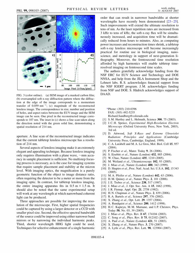
aperture. A line scan of the reconstructed image indicatesthat the current tabletop lensless microscope has a resolu-tion of 214 nm.
Several aspects of lensless imaging make it an extremelyelegant and appealing technique. Because lensless imagingonly requires illumination with a plane wave, �mm accu-racy in sample placement is sufficient. No multistep focus-ing process is necessary, as is the case for imaging systemsthat require sample placement and stability at the micronlevel. With imaging optics, the magnification is a purelygeometric function of the object to image distance ratio,often requiring the detector to be a meter or more from theimaging optic. In contrast, for tabletop lensless imaging,the entire imaging apparatus fits in 0:5 m� 1:5 m. Itshould also be noted that the same experimental setupwill work at any wavelength at which narrowband coherentlight can be produced.
Three approaches are possible for improving the reso-lution of the microscope. First, higher spatial frequenciescould be captured by using a larger detector or a CCD withsmaller pixel size. Second, the effective spectral bandwidthof the source could be improved using either narrower bandmirrors or by narrowing the individual harmonic peaks.Third, shorter wavelength HHG light could be used.Techniques for selective enhancement of a single harmonic
order that can result in narrower bandwidths at shorterwavelengths have recently been demonstrated [23–25].Such improvements will extend the ultimate resolution totens of nm. As the laser repetition rates are increased from3 kHz to tens of kHz, the soft-x-ray flux will be simulta-neously increased, and acquisition time will be dramati-cally reduced from hours to minutes. Also, as computingpower increases and reconstruction times shrink, a tabletopsoft-x-ray lensless microscope will become increasinglypractical for routine use in biological imaging, nano-science, and metrology in support of next-generation li-thography. Moreover, the femtosecond time resolutionafforded by high harmonics will enable tabletop time-resolved imaging on femtosecond time scales.
The authors gratefully acknowledge funding from theNSF ERC for EUV Science and Technology and DOENNSA, and help from the JILA Instrument Shop and theLehnert labs. R. S. acknowledges financial support fromthe NSF IGERT program. J. M. acknowledges fundingfrom NSF and DOE. S. Hadrich acknowledges support ofDAAD.
*Phone: (303) 210-0396FAX: (303) [email protected]
[1] S. M. Hurtley and L. Helmuth, Science 300, 75 (2003).[2] J. C. H. Spence, Experimental High-Resolution Electron
Microscopy (Oxford University Press, New York, 2003),3rd ed.
[3] D. Attwood, Soft X-Rays and Extreme UltravioletRadiation: Principles and Applications (CambridgeUniversity Press, Cambridge, England, 1999).
[4] C. A. Larabell and M. A. Le Gros, Mol. Biol. Cell 15, 957(2004).
[5] P. Fischer et al., Mater. Today 9, 26 (2006).[6] S. Eisebitt et al., Nature (London) 432, 885 (2004).[7] W. Chao, Nature (London) 435, 1210 (2005).[8] M. Weiland et al., Ultramicroscopy 102, 93 (2005).[9] J. Miao et al., Nature (London) 400, 342 (1999).
[10] D. Shapiro et al., Proc. Natl. Acad. Sci. U.S.A. 102, 15 343(2005).
[11] M. A. Pfeifer et al., Nature (London) 442, 63 (2006).[12] H. M. Quiney et al., Nature Phys. 2, 101 (2006).[13] J. E. Trebes et al., Science 238, 517 (1987).[14] J. Miao et al., J. Opt. Soc. Am. A 15, 1662 (1998).[15] J. R. Fienup, Appl. Opt. 21, 2758 (1982).[16] H. N. Chapman et al., Nature Phys. 2, 839 (2006).[17] R. A. Bartels et al., Science 297, 376 (2002).[18] X. Zhang et al., Opt. Lett. 29, 1357 (2004).[19] A. Rundquist et al., Science 280, 1412 (1998).[20] H. C. Kapteyn, M. M. Murnane, and I. P. Christov, Phys.
Today 58, No. 03, 39 (2005).[21] J. Miao et al., Phys. Rev. B 67, 174104 (2003).[22] C. Song et al., Phys. Rev. B 75, 012102 (2007).[23] A. Paul et al., Nature (London) 421, 51 (2003).[24] X. Zhang et al., Nature Phys. 3, 270 (2007).[25] A. Lytle et al., Phys. Rev. Lett. 98, 123904 (2007).
FIG. 3 (color online). (a) SEM image of a masked carbon film;(b) oversampled soft-x-ray diffraction pattern where the diffrac-tion at the edge of the image corresponds to a momentumtransfer of 0:059 nm�1; (c) magnitude of the reconstructedlensless image. The correspondence in size, number and positionof holes, and aspect ratios between the EUV image and the SEMimage can be seen. One pixel in the reconstructed image corre-sponds to 107 nm. The inset in (c) shows a line scan taken alongthe direction noted with the green solid line, demonstrating aspatial resolution of 214 nm.
PRL 99, 098103 (2007) P H Y S I C A L R E V I E W L E T T E R S week ending31 AUGUST 2007
098103-4