Embed Size (px)
Citation preview
Version 1.0 2010.01
Hardware Replacement GuideC310/C315 Series
31041677

Hardware Replacement Guide
Contents
Overview ......................................................................................1
Chapter 1 Locations ................................................................. 5Locating components and connectors ...........................................5
Chapter 2 Replacing hardware ............................................... 9General information ........................................................................9
Replacing a memory module ........................................................9
Replacing the keyboard ..............................................................12
Replacing the mouse ...................................................................13
Replacing the power cord or power adapter ................................14
Appendix. .................................................................................. 15
1Hardware Replacement Guide
Overview
This guide is intended to be used by customers who are replacing Customer Replaceable Units (CRUs) as well as trained service personnel who are replacing Field Replaceable Units (FRUs). In this guide, CRUs and FRUs will often be referred to as parts.
Note: Trained service personnel should refer to the Hardware Maintenance Manual (HMM) for parts ordering information.
This guide does not include procedures for all parts. It is expected that cables, switches, and certain mechanical parts can be replaced by trained service personnel without the need for step-by-step procedures.
Note: Use only parts provided by Lenovo®.
The description of the TV-Tuner card in this manual applies only to those computer models that have the TV-Tuner card installed. It does not apply to those computer models that do not have the TV-Tuner card installed.
This guide contains procedures for replacing the following parts:
• Memorymodules
• Keyboard,Mouse(wired)
• Powercord,Poweradapter
Safety information for replacing CRUs
Do not open your computer or attempt any repair before reading the “Important safety information” in the Safety and Warranty Guide that was included with your computer. If you no longer have this copy of the Safety and Warranty Guide, you can obtain one online from the Support Web site at http://consumersupport.lenovo.com.
Additional information resources
If you have Internet access, the most up-to-date information for your computer is available from the World Wide Web.
You can find the following information:
• CRUremovalandinstallationinformation
2 Hardware Replacement Guide
• Publications
• Troubleshootinginformation
• Partsinformation
• Linkstootherusefulsourcesofinformation
To access this information, go to: http://consumersupport.lenovo.com.
Tools required
To disassemble the computer, you need the following tools:
• Wristgroundingstrapandconductivematforpreventingelectrostaticdischarge
• Flatscrewdriver
• Phillipsscrewdriver
• Hexscrewdriver
• Plasticflatscrewdriver
• Plastictweezers
Note: Thescrewsforthedifferentcomponentsvaryinsize.Duringthedisassembly procedure, group the screws with their corresponding components to avoid a mismatch when replacing the components.
Handling static-sensitive devices
Static electricity, although harmless to you, can seriously damage computer components.
When you are replacing a part, do not open the static-protective package containing the new part until the defective part has been removed from the computer and you are ready to install the new part.
When you handle parts and other computer components, take these precautions to avoid static-electricity damage:
• Limityourmovement.Movementcancausestatic-electricitytobuilduparoundyou.
• Alwayshandlepartsandothercomputercomponentscarefully.Handleadapters, memory modules, system boards, and microprocessors by the edges. Never touch any exposed circuitry.
• Preventothersfromtouchingthepartsandothercomputercomponents.
3Hardware Replacement Guide
• Beforeyoureplaceanewpart,touchthestatic-protectivepackagecontainingthe part to a metal expansion-slot cover or other unpainted metal surface on the computer for at least two seconds. This reduces static electricity in the package and your body.
• Whenpossible,removethenewpartfromthestatic-protectivepackaging,and install it directly in the computer without setting the part down. When this is not possible, place the static-protective package that the part came in on a smooth, level surface and place the part on it.
• Donotplacethepartonthecomputercoverorothermetalsurface.

4 Hardware Replacement Guide
5Hardware Replacement Guide
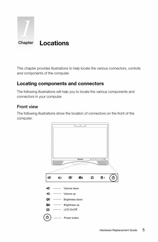
LocationsChapter
This chapter provides illustrations to help locate the various connectors, controls and components of the computer.
Locating components and connectors
The following illustrations will help you to locate the various components and connectors in your computer.
Front view The following illustrations show the location of connectors on the front of the computer.
LCD On/Off
Brightness up
Volume up
Brightness down
Volume down
Power button

6 Hardware Replacement Guide
Left and right viewThe following illustrations show the location of connectors on the left and right side of the computer.
Attention: Besurenottoblockanyairventsonthecomputer.Blockedairvents may cause thermal problems.
1 2 3
Memory card reader Optical drive slot
USBports(2)
7Hardware Replacement Guide
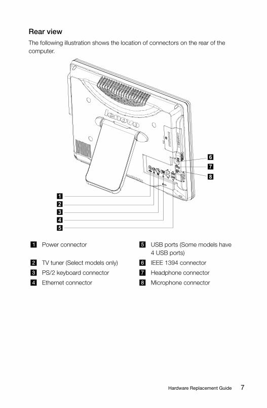
Rear viewThe following illustration shows the location of connectors on the rear of the computer.
1
2
3
4
5
6
7
8
Powerconnector USBports(Somemodelshave4USBports)
TV tuner (Select models only) IEEE 1394 connector
PS/2keyboardconnector Headphone connector
Ethernet connector Microphone connector

8 Hardware Replacement Guide
9Hardware Replacement Guide
Attention:
Do not remove the computer cover or attempt any repair before reading the “Important safety information” in the Safety and Warranty Guide that was included with your computer or in the Hardware Maintenance Manual (HMM) for the computer. To obtain copies of the Safety and Warranty Guide or HMM, go to the Support Web site at http://consumersupport.lenovo.com.
Note: Use only parts provided by Lenovo.
General information
Pre-disassembly instructions
Beforeproceedingwiththedisassemblyprocedure,makesurethatyoudothefollowing:
1. Turn off the power to the system and all peripherals.
2. Unplug all power and signal cables from the computer.
3.Placethesystemonaflat,stablesurface.
Replacing a memory module
Attention:
Turn off the computer and wait 3 to 5 minutes to let the computer cool before removing the computer cover.
To remove the computer cover:
Note: For this procedure, it helps to place the computer face-down on a soft flatsurface.Lenovorecommendsthatyouuseablanket,towel,orothersoftcloth to protect the touch screen surface from scratches or other damage.
Replacing hardware Chapter
10 Hardware Replacement Guide
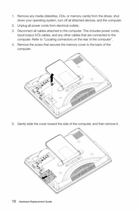
1. Remove any media (diskettes, CDs, or memory cards) from the drives, shut down your operating system, turn off all attached devices, and the computer.
2. Unplug all power cords from electrical outlets.
3. Disconnect all cables attached to the computer. This includes power cords, input/output (I/O) cables, and any other cables that are connected to the computer. Refer to “Locating connectors on the rear of the computer”.
4. Remove the screw that secures the memory cover to the back of the computer.
5. Gently slide the cover toward the side of the computer, and then remove it.
11Hardware Replacement Guide
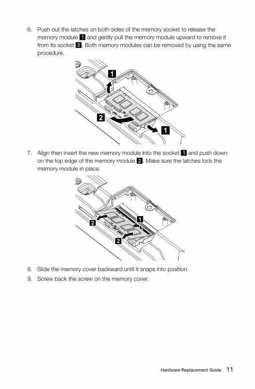
6. Pushoutthelatchesonbothsidesofthememorysockettoreleasethememory module and gently pull the memory module upward to remove it from its socket .Bothmemorymodulescanberemovedbyusingthesameprocedure.
1
1
2
7. Aligntheninsertthenewmemorymoduleintothesocket and push down on the top edge of the memory module . Make sure the latches lock the memory module in place.
21
2
8. Slide the memory cover backward until it snaps into position.
9. Screw back the screw on the memory cover.
12 Hardware Replacement Guide
Replacing the keyboard
Attention:
Do not remove the computer cover or attempt any repair before reading the “Important safety information” in the Safety and Warranty Guide that was included with your computer or in the Hardware Maintenance Manual (HMM) for the computer. To obtain copies of the Safety and Warranty Guide or HMM, go to the Support Web site at http://consumersupport.lenovo.com.
To replace the keyboard:
1. Remove any media (diskettes, CDs, or memory cards) from the drives, shut down your operating system, and turn off all attached devices and the computer.
2. Unplug all power cords from electrical outlets.
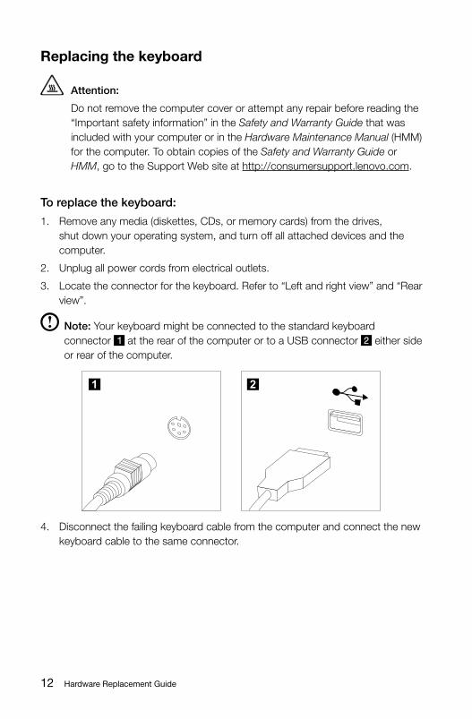
3. Locate the connector for the keyboard. Refer to “Left and right view” and “Rear view”.
Note: Your keyboard might be connected to the standard keyboard connector attherearofthecomputerortoaUSBconnector either side or rear of the computer.
1 2
4. Disconnect the failing keyboard cable from the computer and connect the new keyboard cable to the same connector.
13Hardware Replacement Guide
Replacing the mouse
Attention:
Do not remove the computer cover or attempt any repair before reading the “Important safety information” in the Safety and Warranty Guide that was included with your computer or in the Hardware Maintenance Manual (HMM) for the computer. To obtain copies of the Safety and Warranty Guide or HMM, go to the Support Web site at http://consumersupport.lenovo.com.
To replace the mouse:
1. Remove any media (diskettes, CDs, or memory cards) from the drives, shut down your operating system, and turn off all attached devices and the computer.
2. Unplug all power cords from electrical outlets.
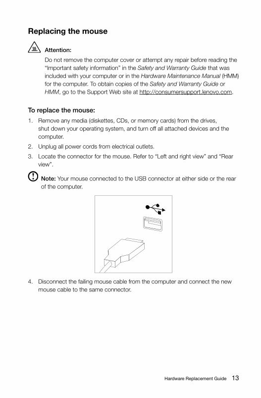
3. Locate the connector for the mouse. Refer to “Left and right view” and “Rear view”.
Note: YourmouseconnectedtotheUSBconnectorateithersideortherearof the computer.
4. Disconnect the failing mouse cable from the computer and connect the new mouse cable to the same connector.
14 Hardware Replacement Guide
Replacing the power cord or power adapter
Attention: Do not remove the computer cover or attempt any repair before reading the
“Important safety information” in the Safety and Warranty Guide that was included with your computer or in the Hardware Maintenance Manual (HMM) for the computer. To obtain copies of the Safety and Warranty Guide or HMM, go to the Support Web site at http://consumersupport.lenovo.com.
To replace the power cord and power adapter:
1. Remove any media (diskettes, CDs, or memory cards) from the drives, shut down your operating system, and turn off all attached devices and the computer.
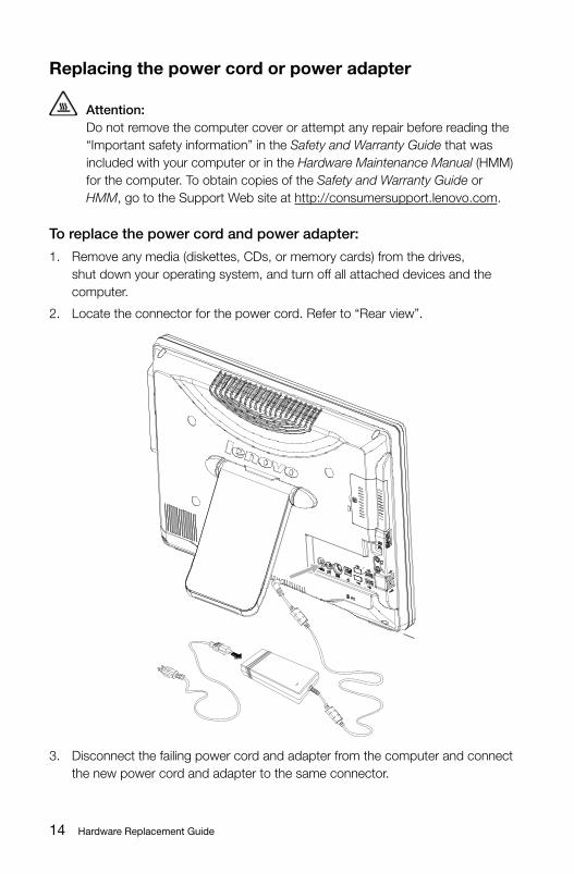
2. Locate the connector for the power cord. Refer to “Rear view”.
3. Disconnect the failing power cord and adapter from the computer and connect the new power cord and adapter to the same connector.
15Hardware Replacement Guide
Appendix.
Statement
Thanks for using Lenovo products.Carefully read all of the documents shipped with your computer before you install and use the product for the first time. Lenovo will not assume responsibility for damage that results from failure to operate the product according to instructions and requirements described in the manuals included with your computer. Lenovo will not assume responsibility for any loss caused except that caused by the installation or operations carried out by Lenovo professional service staff.
Lenovo has made every attempt to ensure that the manuals included with your computer, are correct and accurate, but makes no guarantee that the publications are error free.To provide better service, Lenovo reserves the right to improve and/or modify the products and software programs described in the manuals included with your computer and the content of the manual at any time without additional notice.
AllofthemanualsincludedwithyourcomputerareprovidedtohelpyouuseLenovo products appropriately, but do not provide any description of the software/hardware configuration for the product. For the configuration of the product, refer to related contract (if any), product packing list for the product or retailer.The content of the manuals included with your computer is protected by copyright laws and rules. None of the manuals included with your computer may be reproduced or transcribed by any means, or transmitted through wired or wireless network in any form, or translated into any language without prior written permissionofLenovo.AllLenovopublicationsincludedwithyoursystemareprotected by Copyright © 2010 Lenovo.
The software and hardware configuration included with your computer depends on the actual configuration of the computer and may differ from other similar models.
Customers are welcome to contact us for any inconsistency between the product and the manuals included with your computer. For the latest information or any questions or comments, please visit consumer support website at: http://consumersupport.lenovo.com
16 Hardware Replacement Guide
Lenovo is a registered trademark of Lenovo.
Microsoft, Windows, and Windows Vista are trademarks of the Microsoft group of companies.
Intel Inside is the registered trademark of Intel.
AMD,theAMDArrowlogo,ATI,theATIlogo,AMDAthlon,AMDLIVE,AMDOpteron,AMDPhenom,AMDSempron,Avivo,Catalyst,Cool'n'Quiet,CrossFireX,Overdrive,Powerplay,Radeon,TheUltimateVisualExperience,andcombinationsthereofaretrademarksofAdvancedMicroDevices,Inc.intheUnitedStatesand/or other jurisdictions.
The table above includes the logo and registered trademarks of Lenovo and its partners.
Other registered trademarks mentioned in all the manuals included with your computer belong to the specific company respectively.
The manual included with your computer is protected by copyright laws and rules. None of the manuals included with your computer may be reproduced or transcribed by any means, or transmitted through wired or wireless network in any form, or translated into any language without prior written permission of Lenovo.
Names or marks of certain companies mentioned in the manuals included with your computer or this document are only used to state trademark rights, and they will not necessarily indicate that related software or hardware is included. The concrete configuration of the product depends on the description of the specific model.