Embed Size (px)
Citation preview
LEITZ means precision -worldwide.
" = Registered Trademark Des ign subject to alterations without notice.
ERNST LEITZ Wri:TZLAR GMBH D-6330 Wetzlar Tel. : (06441) 291 Telex : 483 84'3 leiz d
Subsidiary : Erns! Leitz (Canada) Ltd ., Midland, On tario Leitz Portugal S.A.R.L., Vi la Nova de Famalicao
List I 512-150/Eng I. I Pr inted in W-Germany I/77/GX/SD
LEITZ DIALUX 20 Laboratory and Research Microscope
Instructions
Leitz instruments are guaranteed for two years
against manufacturing defects when purchased
through an authorized dealer and registered
with E. Leitz, Inc. Rockleigh, N. J., within 10
days of receipt. A registration card is enclosed
with each instruntent for this purpose.
512-150/Engl. I
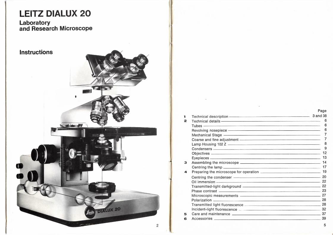
LEITZ DIALUX 20 Laboratory and Research Microscope
Instructions
Page
1 Technical description 3 and 38 2 Technical details 6
Tubes 6
Revolving nosepiece 6
Mechanical Stage 7
Coarse and fine adjustment 7
Lamp Housing 102 Z 8
Condensers 9
Objectives 12
Eyepieces 13
3 Assembling the microscope 14 Centring the lamp 17
4 Preparing the microscope for operation 19
Centring the condenser 20
Oil immersion 22
Transmitted-light darkground 22
Phase contrast 23
Microscopic measurements 27 Polarization 28 Transmitted light fluorescence 28
Incident-light fluorescence 32 5 Care and maintenance 37 6 Accessories 39
2 5
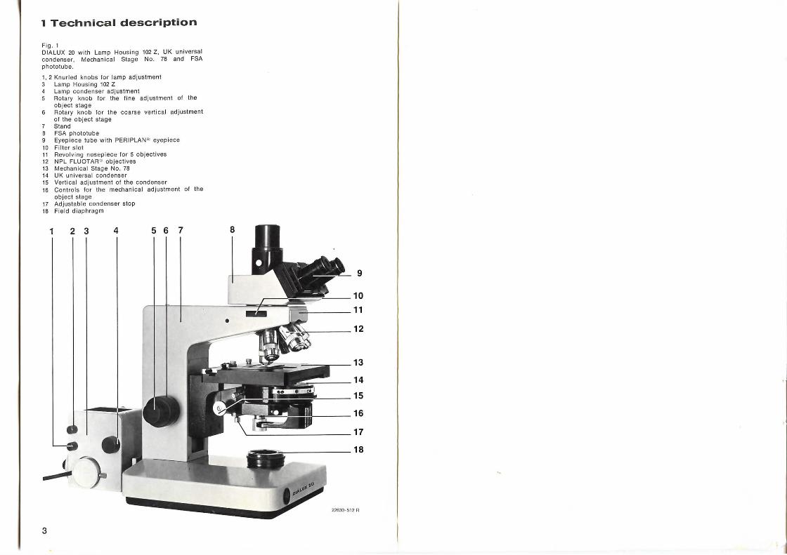
1 Technical description
Fig . 1 DI ALUX 20 with Lamp Housi ng 102 Z, UK universal condenser , Mechanica l Stage No. 78 and FSA phototube.
1, 2 Knurled knobs for lamp adjustment 3 Lamp Housing 102 Z 4 Lamp condenser adj ustment 5 Rotary knob for the fine adj ustment of the
object stage 6 Rotary knob for the coarse verti cal adjustment
of the object stage 7 Stand 8 FSA phototube 9 Eyepiece tube with PERIPLAN " eyepiece 10 Filter slot 11 Revol ving nosepiece fo r 5 objectives 12 NPL FLUOTAR"' objectives 13 Mechani cal Stage No. 78 14 UK universal condenser 15 Vertical adjustment of the condenser 16 Controls for the mechani ca l adj ustment of the
object stage 17 Adjustable condenser stop 18 Fi eld diaphragm
1 2
3
9
13
:;;o..,.,..-------14
="'----__ 15
2 Technical details
Tubes
• - c; -~ 22639 -5 13 R
22654 -513 R
6
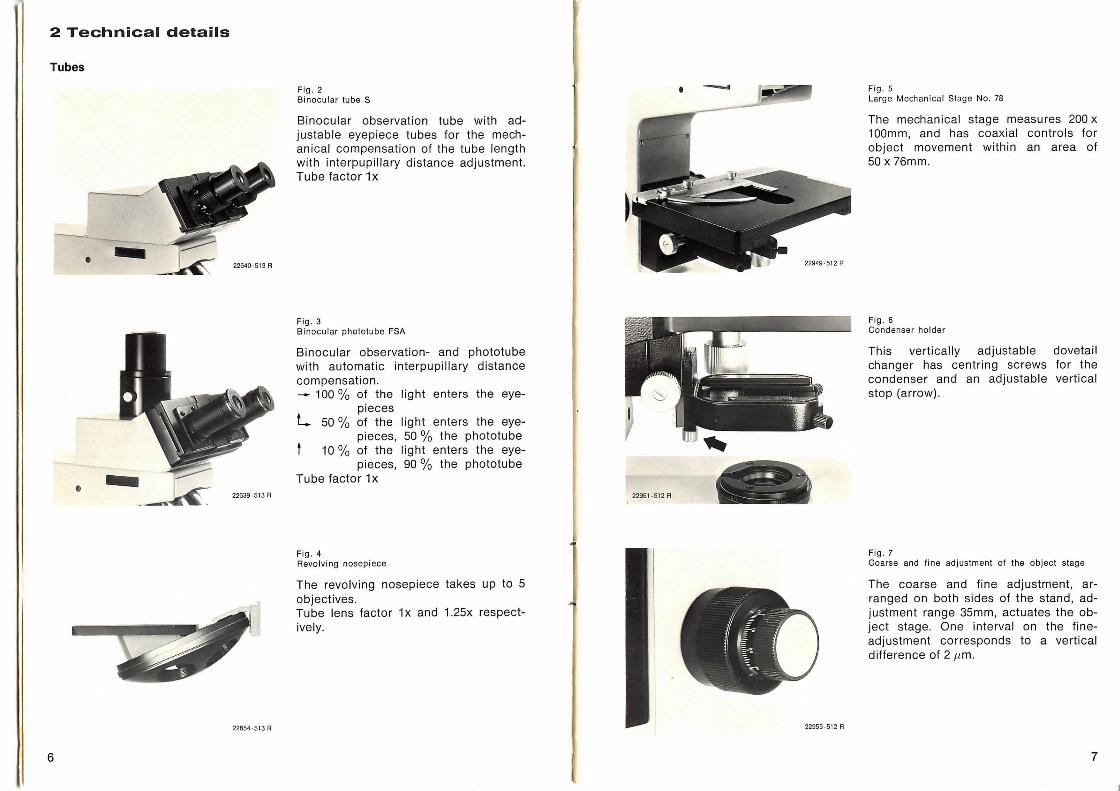
Fig_ 2 Binocular tube S
Binocular observation tube with adjustable eyepiece tubes for the mechanical compensation of the tube length with interpupillary distance adjustment. Tube factor 1x
Fig_ 3 Binocular phototube FSA
Binocular observation- and phototube with automatic interpupillary distance compensation. - 100% of the light enters the eye
pieces L 50% of the light enters the eye
pieces, 50 % the phototube 10% of the light enters the eye
pieces, 90 % the phototube Tube factor 1 x
Fig . 4 Revol ving nosepiece
The revolving nosepiece takes up to 5 objectives. Tube lens factor 1 x and 1.25x respectively.
22951 ·512 R
• -
-__ ,....... _ ..::::._ ..:
"'-. : l -----,--
22955-51 2 R
Fig. 5 Larg e Mechanical Stage No. 78
The mechanical stage measures 200 x 100mm, and has coaxial controls for object movement within an area of 50 x 76mm.
Fig . 6 Condenser holder
This vertically adjustable changer has centring screws condenser and an adjustable stop (arrow).
Fig. 7
dovetail for the vertical
Coarse and fine adjustment of the obj ect stage
The coarse and fine adjustment, arranged on both sides of the stand, adjustment range 35mm, actuates the object stage. One interval on the fineadjustment corresponds to a vertical difference of 2 ,um.
7
22656 · 514 A
22962· 514 R
8
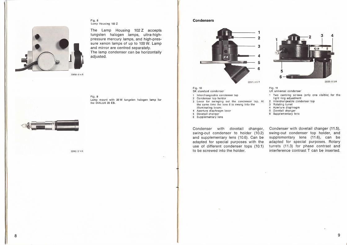
Fig . 8 Lamp Housing 102 Z
The Lamp Housing 102 Z accepts tungsten halogen lamps, ultra-highpressure mercury lamps, and high-pressure xenon lamps of up to 100 W. Lamp and mirror are centred separately. The lamp condenser can be horizontally adjusted .
Fig . 9 Lamp mount w ith 20 W tungsten halogen lamp for the DIALUX 20 EB.
Condensers
Fig. 10 SK stand ard cond enser
1 In terchangeabl e cond enser top 2 Condenser top holder
1 2
3
4
5
6
3 Lever fo r sw inging out the condenser to p. At the same time the lens 6 is swung into the i ll uminating beam;
4 Aperture di aphrag m lever 5 Dove tai l changer 6 Supplementary lens
Condenser with dovetail changer, swing-out condenser to holder (1 0.2) and supplementary lens (10.6) . Can be adapted for special purposes with the use of different condenser tops (10.1) to be screwed into the holder.
22655·513 R
Fig. 11 UK unive rsa l condenser
1 Two cen tring sc rews (o nly one visib le) for the li ght rin g adjustment
2 In te rchangeabl e condenser top 3 Rota ting turret 4 Aperture di aphrag m 5 Dovetail changer 6 Suppl ementary lens
Condenser with dovetail changer (11 .5) , swing-out condenser top holder, and supplementary lens (11 .6), can be adapted for special purposes. Rotary turrets (11.3) for phase contrast and interference contrast T can be inserted .
9
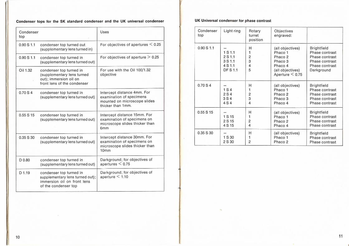
. Condenser tops for the SK standard condenser and the UK universal condenser UK Universal condenser for phase contrast
Condenser Uses Condenser Light ring Rotary Objectives
top top turret engraved: position
0.90 81.1 condenser top turned out For objectives of apertures < 0.25 (supplementary lens turned in) 0.90 8 1.1 - H (all objectives) Brightfield
1 8 1.1 1 Phaco 1 Phase contrast 0.90 8 1.1 condenser top turned in For objectives of aperture > 0.25 2 8 1.1 2 Phaco 2 Phase contrast
(supplementary lens turned out) 3 8 1.1 3 Phaco 3 Phase contrast 4 8 1.1 4 Phaco 4 Phase contrast
Oil1 .32 condenser top turned in For use with the Oil100/1.32 OF 8 1.1 5 (all objectives) Darkground (supplementary lens turned objective Aperture < 0.75 out) ; immersion oil on front lens of the condenser 0.70 8 4 - H (all objectives) Brightfield
0.70 8 4 condenser top turned in Intercept distance 4mm. For (supplementary lens turned out) examination of specimens
mounted on microscope slides thicker than 1 mm.
1 8 4 1 Phaco 1 Phase contrast 284 2 Phaco 2 Phase contrast 384 3 Phaco 3 Phase contrast 484 4 Phaco 4 Phase contrast
0.55 8 15 condenser top turned in Intercept distance 15mm. For (supplementary lens turned out) examination of specimens on
microscope slides thicker than 6mm
0.55 8 15 - H (all objectives) Brightfield 1 8 15 1 Phaco 1 Phase contrast 2 815 2 Phaco 2 Phase contrast 4 815 4 Phaco 4 Phase contrast
0.35 8 30 - H (all objectives) Brightfield 0.35 8 30 condenser top turned in Intercept distance 30mm. For 1 8 30 1 Phaco 1 Phase contrast
(supplementary lens turned out) examination of specimens on 2 8 30 2 Phaco 2 Phase contrast microscope slides thicker than 10mm
D 0.80 condenser top turned in Darkground; for objectives of (supplementary lens turned out) apertures < 0.75
D 1.19 condenser top turned in Darkground ; for objectives of supplementary lens turned out) ; aperture < 1.10 immersion oil on front lens of the condenser top
10 11
Objectives
1__!gl!l! 2 - JW.,.,......:.;::t;;j
3:=;~.:.,-4 5-...... ~~ s-....... ~---~~-. 7-s ;;,.;;:;::;::;:::;:;::
22952-519 R
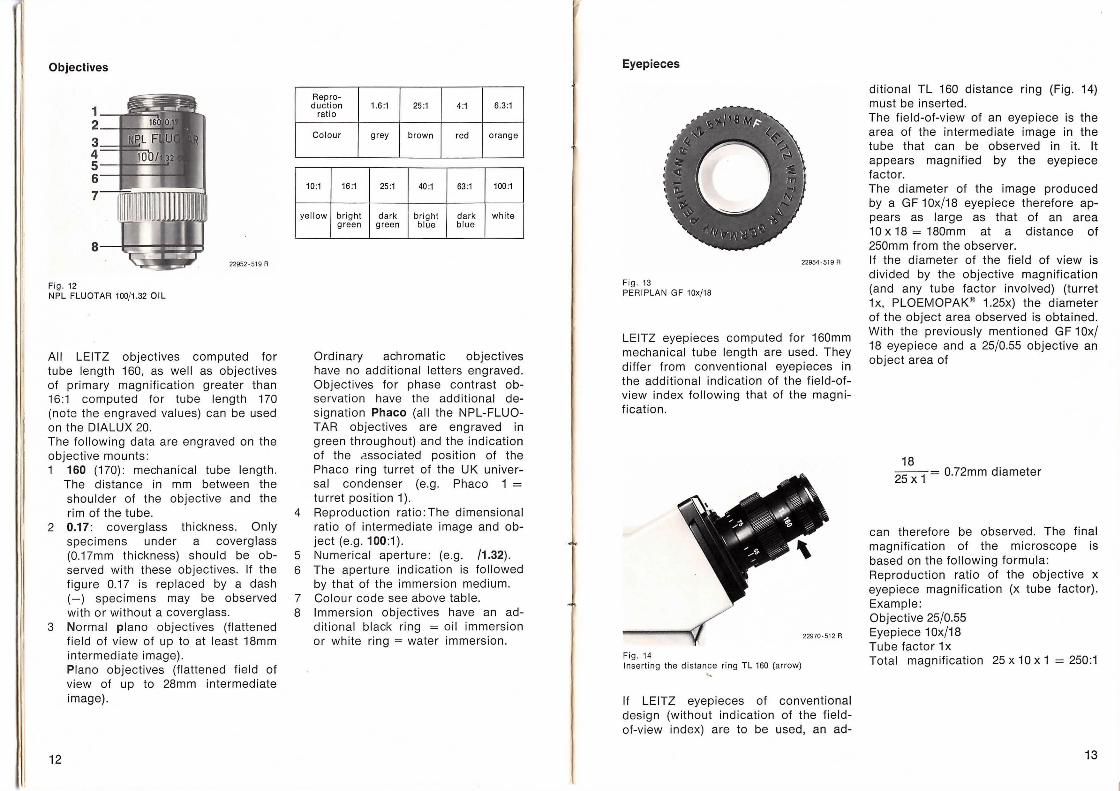
Fig . 12 NPL FLUOTAR 100/1.32 OIL
All LEITZ objectives computed for tube length 160, as well as objectives of primary magnification greater than 16:1 computed for tube length 170 (note the engraved values) can be used on the DIALUX 20. The following data are engraved on the objective mounts: 1 160 (170) : mechanical tube length.
The distance in mm between the shoulder of the objective and the rim of the tube.
2 0.17: coverglass thickness. Only specimens under a coverglass (0.17mm thickness) should be observed with these objectives. If the figure 0.17 is replaced by a dash (-) specimens may be observed with or without a coverglass.
3 Normal piano objectives (flattened field of view of up to at least 18mm intermediate image).
12
Piano objectives (flattened field of view of up to 28mm intermediate image).
Repro-duction 1.6:1 25:1 4:1 6.3:1
ratio
Col our grey brown red orange
10:1 16:1 25 :1 40:1 63 :1 100 :1
yellow bright dark bright dark white green gree n blue blue
Ordinary achromatic objectives have no additional letters engraved . Objectives for phase contrast observation have the additional designation Phaco (all the NPL-FLUOTAR objectives are engraved in green throughout) and the ind ication of the associated position of the Phaco ring turret of the UK universal condenser (e.g. Phaco 1 = turret position 1 ).
4 Reproduction ratio: The dimensional ratio of intermediate image and object (e.g. 100:1).
5 Numerical aperture : (e.g. /1.32). 6 The aperture indication is followed
by that of the immersion medium. 7 Colour code see above table. 8 Immersion objectives have an ad
ditional black ring = oil immersion or white ring = water immersion.
Eyepieces
22954-519 R
Fig . 13 PERIPLAN GF 10x/18
LEITZ eyepieces computed for 160mm mechanical tube length are used. They differ from conventional eyepieces in the additional indication of the field-ofview index following that of the magnification.
22970-512 R
Fi g. 14 Insertin g the distance ring TL 160 (arrow)
" If LEITZ eyepieces of conventional design (without indication of the fieldof-view index) are to be used, an ad-
ditional TL 160 distance ring (Fig. 14) must be inserted. The field-of-view of an eyepiece is the area of the intermediate image in the tube that can be observed in it it appears magnified by the eyepiece factor. The diameter of the image produced by a GF 10x/18 eyepiece therefore appears as large as that of an area 10 x 18 = 180mm at a distance of 250mm from the observer. If the diameter of the field of view is divided by the objective magnification (and any tube factor involved) (turret 1 x, PLOEMOPAK® 1.25x) the diameter of the object area observed is obtained. With the previously mentioned GF 1 Ox/ 18 eyepiece and a 25/0.55 objective an object area of
18
25 x
1 = 0.72mm diameter
can therefore be observed. The final magnification of the microscope is based on the following formula: Reproduction ratio of the objective x eyepiece magnification (x tube factor) . Example: Objective 25/0.55 Eyepiece 1 Ox/18 Tube factor 1x Total magnification 25 x 10 x 1 = 250:1
13
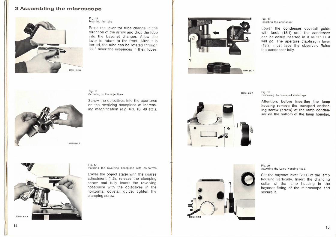
3 Assembling the microscope
14
Fig. 15 Inserting the tube
Press the lever for tube change in the direction of the arrow and drop the tube into the bayonet changer. Allow the lever to return to the front. After it is locked, the tube can be rotated through 360° .lnsertthe eyepieces in their tubes.
Fig . 16 Screwing in the objectives
Screw the objectives into the apertures on the revolving nosepiece at increasing magnification (e .g. 6.3, 16, 40 etc.).
Fi g. 17 Insert ing the revo lving nosepi ece w ith ob jectives
Lower the object stage with the coarse adjustment (1 .6) , release the clamping screw and fully insert the revolving nosepiece with the objectives in the horizontal dovetail guide; tighten the clamping screw.
1
.tO 22636-512 A
-512 A
22956-514 A
Fig. 18 Inserting the condenser
Lower the condenser dovetai l guide with knob (18.1) unti l the condenser can be easi ly inserted in it as far as it will go. The aperture diaphragm lever (18.2) must face the observer. Ra ise the condenser fully.
Fig. 19 Removing the transport anchorage
Attention: before inserting the lamp housing remove the transport anchoring screw (arrow) of the lamp condenser on the bottom of the lamp housing.
Fig. 20 Attaching the Lamp Housi ng 102 Z
Set the bayonet lever (20.1) of the lamp hous ing vertica ll y. Insert the changing collar of the lamp housing in the bayonet fitting of the microscope and secure it.
15
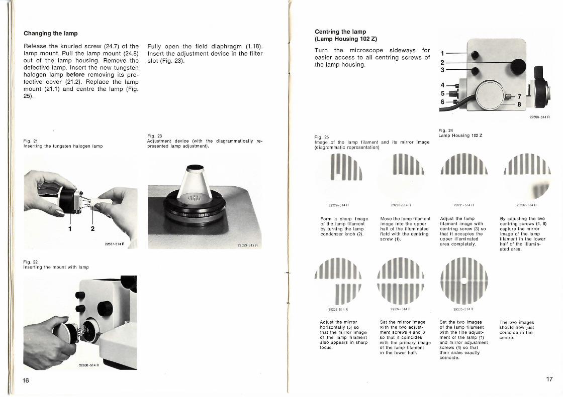
Changing the lamp
Release the knurled screw (24.7) of the lamp mount. Pull the lamp mount (24.8) out of the lamp housing . Remove the defective lamp. Insert the new tungsten halogen lamp before removing its protective cover (21.2) . Replace the lamp mount (21 .1) and centre the lamp (Fig. 25) .
Fig. 21 Inserting the tungsten halogen lamp
22637·514 A
Fig . 22 Inserting the mou nt with lamp
16
Fully open the field diaphragm (1.18) . Insert the adjustment device in the filter slot (Fig. 23).
Fig . 23 Adjustment device (with the diagrammatically represented lamp adjustment).
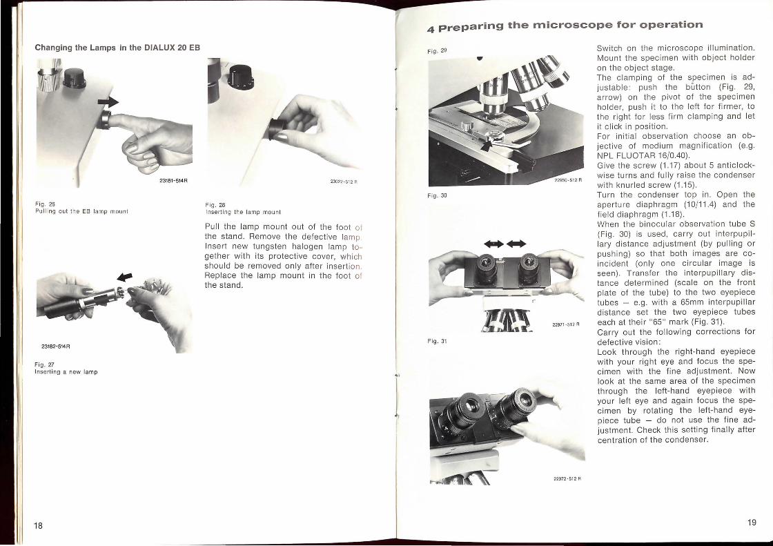
Centring the lamp (Lamp Housing 102 Z)
Turn the microscope sideways for easier access to all centring screws of the lamp housing.
Fig. 25 Image of the lamp filament and its mirror image (diagrammatic representation)
I I ~ 29229-514 A
Form a sharp image of the lamp filament by turning the lamp condenser knob (2).
29233-514 A
Adjust the mirror horizontall y (5) so that the mirror image of the lamp fil ament also appears in sharp foc us.
29230-514 A
Move the lamp filament image into the upper half of the illuminated field with the centring screw (1).
29234-514A
Set the mirror image with the two ad justment screws 4 and 6 so that it coincides with the primary image of the lamp filament in the lower half.
Fig. 24 Lamp Housing 102 Z
29231-514 A
Adjust the lamp fi lament image with centring screw (3) so that it occupi es the upper illuminated area co mpletely.
29235·514 A
Set the two images of the lamp filament with the fin e adjustment of the lamp (1) and mirror adjustment screws (4) so that their sides exactly coincide.
22656·5 14 A
29232·514 A
By ad justing the two centri ng screws (4, 6) capture the mirror image of the lamp filament in the lower half of the illuminated area.
The two images should now just co incide in the centre.
17
Changing the Lamps in the DIALUX 20 EB
23181-514R
Fig. 26 Pull ing out th e EB lamp mount
Fig . 27 Insert ing a new lamp
18
23022-5 12 A
Fig. 28
Inserting th e lamp mount
Pull the lamp mount out of the foot of the stand. Remove the defective lamp Insert new tungsten halogen lamp together with its protective cover, which should be removed only after inserti on . Replace the lamp mount in the foot of the stand.
...
4 preparing the microscope for operation
Fig . 29
Fig. 30
....
.liE_ Fig. 31
22972-512 A
Switch on the microscope illumination. Mount the specimen with object holder on the ob ject stage. The c lamping of the specimen is adjustab le: push the button (Fig. 29, arrow) on the pivot of the spec imen holder, push it to the left for firmer, to the right for less firm clamping and let it cl ick in position. For initial observation choose an objective of medium magnification (e.g . NPL FLUOTAR 16/0.40). Give the screw (1 .17) about 5 anticlockwise turns and fully raise the condenser with knurled screw (1.15). Turn the condenser top in. Open the aperture diaphragm (10/11.4) and the field diaphragm (1.18). When the binocular observation tube S (Fig . 30) is used, carry out interpupillary distance adjustment (by pulling or pushing) so that both images are coincident (only one circular image is seen). Transfer the interpupillary distance determined (scale on the front plate of the tube) to the two eyepiece tubes - e.g. with a 65mm interpupillar distance set the two eyepiece tubes each at their "65" mark (Fig. 31). Carry out the fo ll owing corrections for defective vision: Look through the right-hand eyepiece with your right eye and focus the specimen w ith the fine adjustment. Now look at the same area of the specimen through the left-hand eyepiece with your left eye and again focus the specimen by rotating the left-hand eyepiece tube - do not use the fine adjustment. Check this setting finally after centration of the condenser.
19
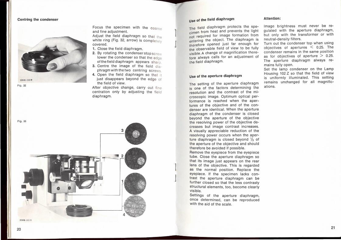
Centring the condenser
Fig . 32
Fig. 33
. .
' -- -r •Ju, l!loltl!
~ 22958-512 A
20
Focus the specimen with the coarse and fine adjustment. Adjust the field diaphragm so that the white ring (Fig. 32, arrow) is com pletely covered. 1. Close the field diaphragm. 2. By rotating the condenser stop sc rew
lower the condenser so that the edge of the field diaphragm appears sharp.
3. Centre the image of the field di aphragm with the two centring sc rews.
4. Open the field diaphragm so that it just disappears beyond the edge of the field of view.
After objective change, carry ou t fi ne centration only by adjusting the fi eld diaphragm.
[
t
use of the field diaphragm
The field diaphragm protects the specimen from heat and prevents the light not required for image formation from entering the object. The diaphragm is therefore opened just far enough for the observable field of view to be fully visible. A change of magnification therefore always calls for an adjustment of the field diaphragm.
Use of the aperture diaphragm
The setting of the aperture diaphragm is one of the factors determining the resolution and the contrast of the microscopic image. Optimum optical performance is reached when the apertures of the objective and of the condenser are identical. When the aperture diaphragm of the condenser is closed beyond the aperture of the objective the resolving power of the objective decreases but image contrast increases. A visually appreciable reduction of the resolving power occurs when the aperture diaphragm is closed beyond lj3 of the aperture of the objective and should therefore be avoided if possible. Remove the eyepiece from the eyepiece tube. Close the aperture diaphragm so that its image just appears on the rear lens of the objective. This is regarded as the normal position . Replace the eyepiece. If the specimen lacks contrast the aperture diaphragm can be further closed so that the less contrasty structural elements, too, become clearly visible. Settings of the aperture diaphragm, once determined, can be reproduced with the aid of the scale.
Attention:
Image brightness must never be regulated with the aperture diaphragm, but only with the transformer or with neutral-density filters. Turn out the condenser top when using objectives of apertures < 0.25. The condenser remains in the same position as for objectives of aperture > 0.25. The aperture diaphragm always remains fully open. Set the lamp condenser on the Lamp Housing 102 Z so that the field of view is uniformly illuminated. This setting remains unchanged for all magnifications.
21
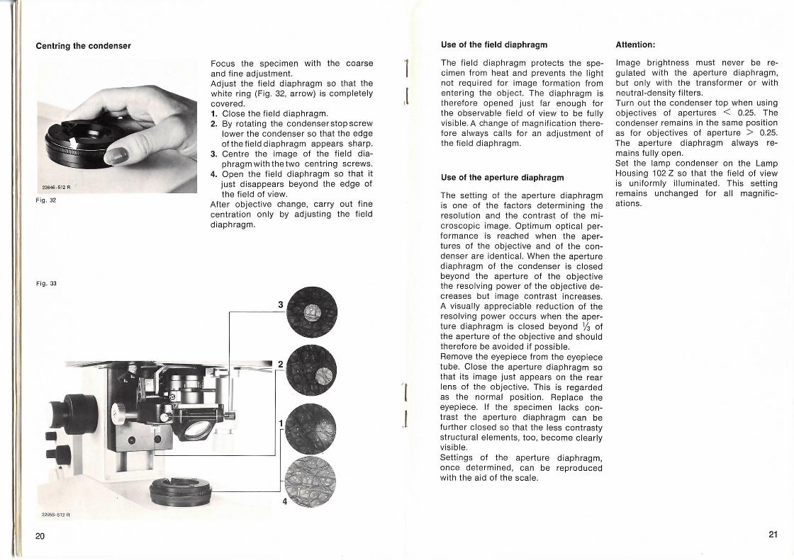
Centring the condenser
Fig . 32
Fig. 33
22958 · 512 A
.I 20
I
- -- -YL -----.... -
Focus the specimen with the coarse and fine adjustment. Adjust the field diaphragm so that the white ring (Fig . 32, arrow) is completely covered. 1. Close the field diaphragm. 2. By rotating the condenser stop screw
lower the condenser so that the edge of the field diaphragm appears sharp.
3. Centre the image of the field diaphragm with the two centring screws.
4. Open the field diaphragm so that it just disappears beyond the edge of the field of view.
After objective change, carry out fine centration only by adjusting the field diaphragm.
'(
.l
Use of the field diaphragm
The field diaphragm protects the specimen from heat and prevents the light not required for image formation from entering the object. The diaphragm is therefore opened just far enough for the observable field of view to be fully visible. A change of magnification therefore always calls for an adjustment of the field diaphragm.
Use of the aperture diaphragm
The setting of the aperture diaphragm is one of the factors determining the resolution and the contrast of the microscopic image. Optimum optical performance is reached when the apertures of the objective and of the condenser are identical. When the aperture diaphragm of the condenser is closed beyond the aperture of the objective the resolving power of the objective decreases but image contrast increases. A visually appreciable reduction of the resolving power occurs when the aperture diaphragm is closed beyond v3 of the aperture of the objective and should therefore be avoided if possible. Remove the eyepiece from the eyepiece tube. Close the aperture diaphragm so that its image just appears on the rear lens of the objective. This is regarded as the normal position . Replace the eyepiece. If the specimen lacks contrast the aperture diaphragm can be further closed so that the less contrasty structural elements, too, become clearly visible. Settings of the aperture diaphragm, once determined, can be reproduced with the aid of the scale.
Attention:
Image brightness must never be regulated with the aperture diaphragm, but only with the transformer or with neutral-density filters . Turn out the condenser top when using objectives of apertures < 0.25. The condenser remains in the same position as for objectives of aperture > 0.25. The aperture diaphragm always remains fully open. Set the lamp condenser on the Lamp Housing 102 Z so that the field of view is uniformly illuminated. This setting remains unchanged for all magnifications.
21
Oil immersion
Oil immersion objectives bear the engraving "OIL" and a black ring round the bottom rim of their mount. The immersion oil has the same refractive index nd = 1.518 as the coverglass and the front lens of the objective. Focal length and working distance of an immersion objective are usually very short. This demands great care during work with such objectives. Use the coarse adjustment only until the immersion objective has entered the oil (look across the top of the slide) . Focusing must now be carried out only with the fine adjustment and constant observation through the eyepiece. Ensure that no air bubbles are present in the immersion oil. Use only LEITZ immersion oil. Even with oil immersion objectives it is generally possible to manage with the condenser top 0.90 S 1.1. If, however, the full aperture of the immersion objective is to be utilized, for instance for the examination of very delicate structures, the aplanatic-achromatic condenser top A 1.32 should be used. Here, immersion oil should be applied also between the condenser top and the underside of the microscope slide. After the examination is completed, the immersion oil must be carefully removed from all areas of application with a soft piece of cloth soaked in petrol or methylated spirit.
22
Transmitted-light darkground
. , ' ----
" "·'"-1'
22957 ·513 A
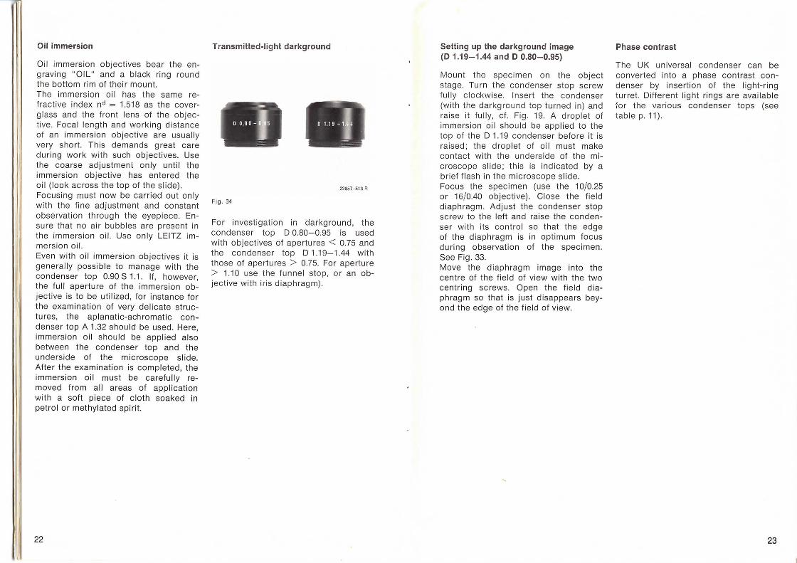
Fig. 34
For investigation in darkground, the condenser top D 0.80-0.95 is used with objectives of apertures < 0.75 and the condenser top D 1.19-1.44 with those of apertures > 0.75. For aperture > 1.10 use the funnel stop, or an objective with iris diaphragm).
Setting up the darkground image (D 1.19-1.44 and D 0.80-0.95)
Mount the specimen on the object stage. Turn the condenser stop screw fully clockwise. Insert the co ndenser (with the darkground top turned in) and raise it full y, cf. Fig. 19. A droplet of immersion oil should be applied to the top of the D 1.19 condenser before it is raised; the droplet of oil must make contact with the underside of the microscope slide; this is indicated by a brief flash in the microscope slide. Focus the specimen (use the 10/0.25 or 16/0.40 objective). Close the field diaphragm. Adjust the condenser stop screw to the left and raise the condenser with its control so that the edge of the diaphragm is in optimum focus during observation of the specimen . See Fig. 33. Move the diaphragm image into the centre of the field of view with the two centring screws. Open the field diaphragm so that is just disappears beyond the edge of the field of view.
Phase contrast
Th e UK universal condenser can be converted into a phase contrast condenser by insertion of the light-ring turret. Different light rings are available ~or the various condenser tops (see table p. 11).
23
Inserting and changing the light rings
All the light rings are marked for the required position in the light-ring turret and fo r the condenser tops to be used for them (see Fig. 35) . Release the Alien screw (2mm) so that the head of the screw is flush with the knurled screw of the light-ring turret. Push the light ring against the sprung holding pin to remove or insert it. Screw the two centring screws in far enough for the light ring to be roughly central (cf. also Fig . 37) . The light -rings must be inserted always in the aperture opposite their position indication (Fig . 36) . The aperture opposite the position indication "H " remains empty, and therefore has no centring screw.
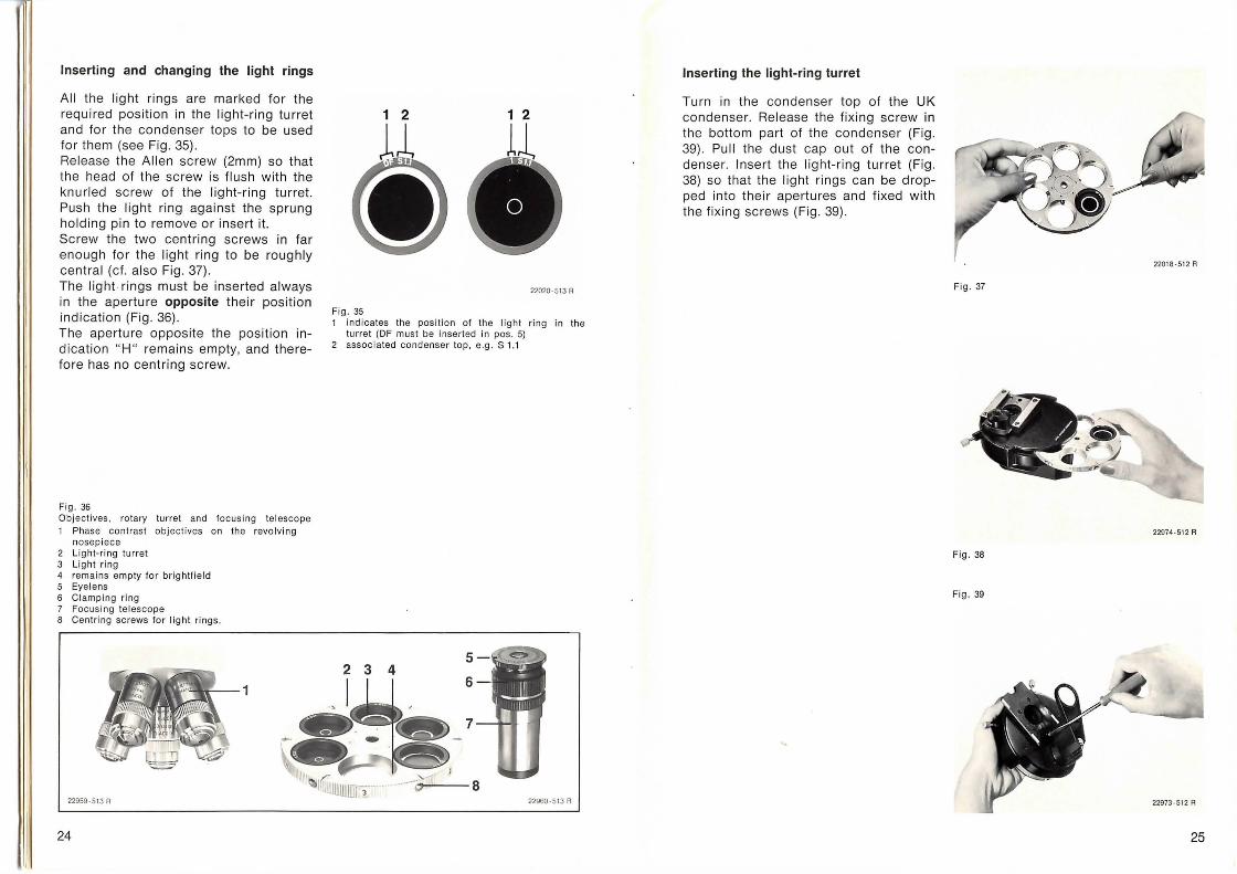
Fig. 36 Objec ti ves, rotary turret and focus ing telescope 1 Phase contrast objec ti ves on the revolving
nosepiece 2 Light-ring turret 3 Light ring 4 remains empty for brightf ie ld 5 Eye lens 6 Clamping ring 7 Focus ing te lescope 8 Cent rin g screws for light rings.
22959 -513 R
24
1 2
s .
D 22020·5 13 R
Fig . 35 1 indi cates the pos ition of th e light r ing in the
turret (OF must be inserted in pas. 5) 2 associated condenser top, e.g. S 1.1
Inserting the light-ring turret
Turn in the condenser top of the UK condenser. Release the fi xi ng screw in the bottom part of the condenser (Fig. 39). Pull the dust cap out of the condenser. Insert the light-ring turret (Fig. 38) so that the light rings can be dropped into their apertures and fi xed with the fi x ing screws (Fig. 39).
Fig. 37
Fig . 38
Fig. 39
22018 · 512 R
22974 -512 R
25
Setting up phase contrast
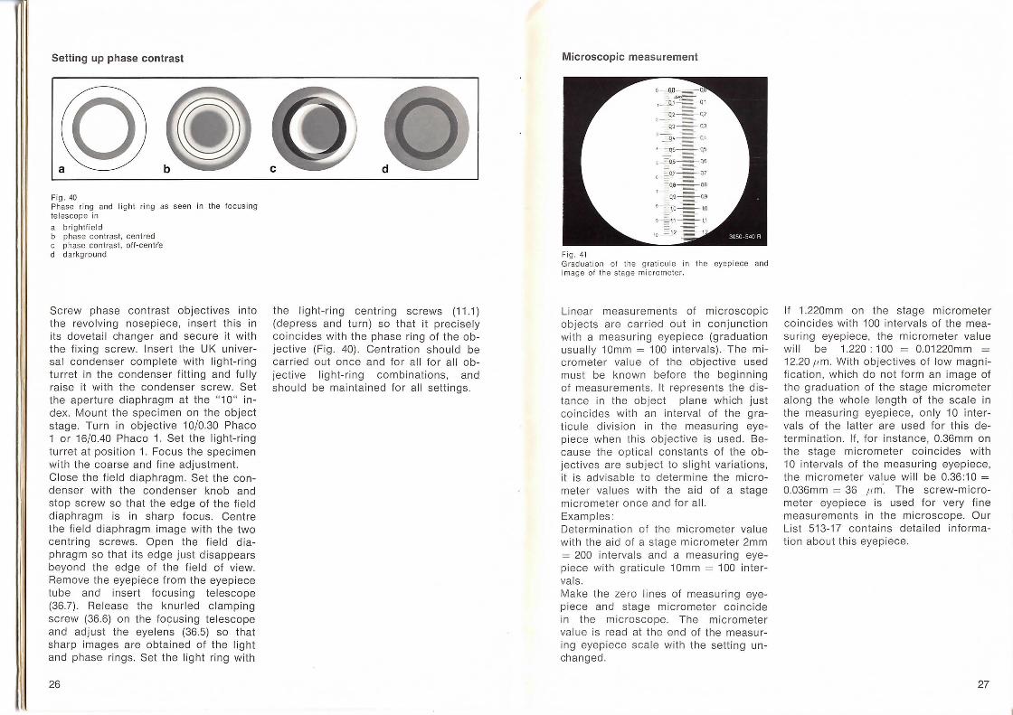
Fig. 40 Ph ase ring and li ght ring as seen in the focusing te lescope in
a brightfield b phase contrast, centred c phase contrast, oil-centre d darkground
Screw phase contrast objectives into the revo lving nosepiece, insert this in its dovetai l changer and secure it with the fixing screw. Insert the UK universa l condenser complete with light-ring turret in the condenser fitting and fully raise it with the condenser screw. Set the aperture diaphragm at the "10" index. Mount the spec imen on the object stage. Turn in objective 10/0.30 Phaco 1 or 16/0.40 Phaco 1. Set the light-ring turret at position 1. Focus the specimen with the coarse and fine ad justment. Close the field diaphragm. Set the condenser with the condenser knob and stop screw so that the edge of the field diaphragm is in sharp focus. Centre the field diaphragm image w ith the two centring screws. Open the field diaphragm so that its edge just disappears beyond the edge of the field of view. Remove the eyepiece from the eyepiece tube and insert focusing telescope (36.7) . Release the knurled clamping screw (36.6) on the focusing telescope and adjust the eye lens (36.5) so that sharp images are obtained of the light and phase rings. Set the light ring w ith
26
the light-ring centring screws (11.1) (depress and turn) so that it prec ise ly coincides with the phase ring of the objective (Fig . 40). Centrat ion shou ld be carried out once and for al l for all objective light-ring combinations, and should be maintained for all sett ings.
Microscopic measurement
Fig. 41 Graduation ol the graticule in the eyepiece and image ol th e stage micrometer.
Linear measurements of microscopic objects are carried out in conjunction wi th a measuring eyep iece (graduation usually 1 Omm = 100 intervals). · The micrometer value of the objective used must be known before the beginning of measurements. lt represents the distance in the ob ject plane wh ich just coincides with an interva l of the graticule division in the measur ing eyepiece when this objective is used. Because the optica l constants of the objectives are subject to slight variations, it is advisable to determine the micrometer values w ith the aid of a stage micrometer once and for all. Examp les: Determination of the micrometer value wi th the aid of a stage micrometer 2mm = 200 interva ls and a measuring eyepiece w ith graticule 10mm = 100 interva ls. Make the zero lines of measuring eyepiece and stage micrometer coincide in the microscope. The micrometer va lue is read at the end of the measuring eyepiece scale with the setting unchanged .
If 1.220mm on the stage micrometer coincides with 100 intervals of the measuring eyepiece, the micrometer value wi ll be 1.220: 100 = 0.01220mm = 12.20 ,um. With objectives of low magnification, wh ich do not form an image of the graduation of the stage micrometer along the whole length of the scale in the measuring eyep iece, on ly 10 interva ls of the latter are used for th is determination . If, for instance, 0.36mm on the stage micrometer coinc ides with 10 intervals of the measuring eyepiece, the micrometer value wi ll be 0.36:10 = 0.036mm = 36 ,um·. The screw-m icrometer eyepiece is used for very fine measurements in the microscope. Our List 513-17 contains detailed informat ion about this eyepiece.
27
Centring the 50 W ultra-high-pressure mercury lamp
microscope. Insert neutral-density screen in the optical path to reduce the lighting intensity. Place the adjustment device on the dustglass of the microscope.
Remove all filters from the filter slot. Fully open the field diaphragm in the
Fig . 45
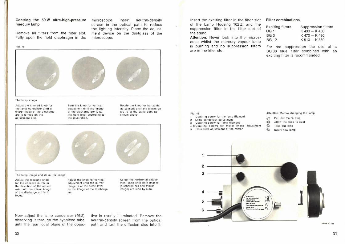
The lamp imag e
Ad just th e knurl ed knob for the lamp co nde nser unti I a sharp image of the discharge arc is fo rm ed on the adjustment d isc.
The lamp image and its mirror imag e
Ad just the focusing knob for the concave mirro r in the direct ion of the optical axis un ti l the mirror image of the discharge arc is in focus.
Turn the kn ob for verti cal adj us tment un ti l the imag e of th e d ischarge arc is at the rig ht level according to the illustrat ion.
Adjust the knob fo r ve rtica l ad justment until the mirror image is at the same leve l as the image of the discharge arc .
Rotate the kno b for horizontal ad jus tm ent unti l th e discharge arc is at the same spot as shown above.
Ad just the horizontal adjustment knob unti l both images (discharge arc and mi rror image) are side by side.
Now adjust the lamp condenser (46.2). obse rving it through the eyepiece tube, unt i l the rear focal plane of the objec-
live is evenly illuminated. Remove the neutral-density sc reen from the optical path and turn the diffusion disc into it.
30
Insert the exciting filter in the filter slot of the Lamp Housing 102 Z, and the suppression filter in the filter slot of the stand . Attention: Never look into the microscope whilst the mercury vapour lamp is burning and no suppression filters are in the filter slot.
Fig . 46 1 Centri ng screw for the lamp fil ament 2 Lamp cond enser adjustment 3 Centr ing screw for lamp fi lament 4, 6 Centri ng screws for mirror image adjustment 5 Hor izonta l adjustment of the mir ro r
1
2
3
4
5
6
Filter combinations
Exciting filters UG 1 BG 3 BG 12
Suppression filters K 430- K 460 K 470- K 490 K 510- K 530
For red suppression the use of a BG 38 blue filter combined with an exciting filter is recommended.
Attention : Before chang ing th e lamp
, :0 Pull out mains pl ug
'* Al low the lamp to cool
' QI Take out lamp
•Q1 Insert new lamp
j 22656 · 514 A
31
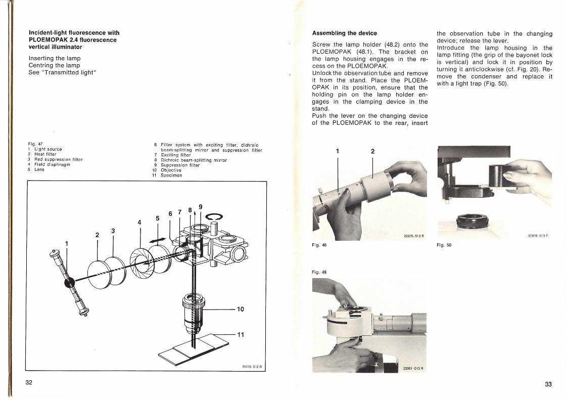
Incident-light fluorescence with PLOEMOPAK 2.4 fluorescence vertical illuminator
Inserting the lamp Centring the lamp See "Transmitted light "
Fig. 47 1 Li ght source 2 Hea t filter 3 Red suppress ion filter 4 Fi eld diap hrag m 5 Lens
32
6 Filter system with exci t ing fil ter, d ichroic beam-splitting mirror and suppress ion fil te r
7 Exc iting filter 8 Di ch ro ic beam-splitting mirror 9 Suppression filter
10 Objective 11 Specimen
6 7 8 9
c:>
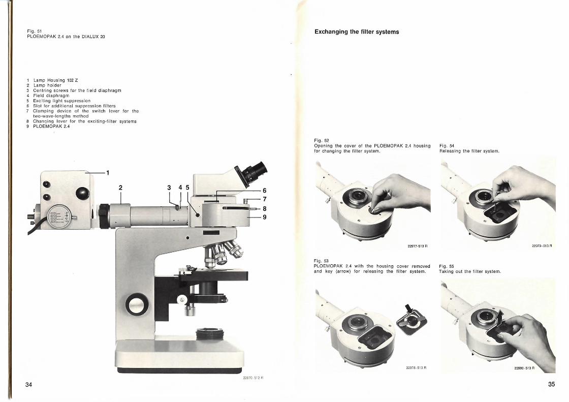
Assembling the device
Screw the lamp holder (48.2) onto the PLOEMOPAK (48.1) . The bracket on the lamp housing engages in the recess on the PLOEMOPAK. Unlock the observation tube and remove it from the stand . Place the PLOEMOPAK in its posit ion, ensure that the holding pin on the lamp holder engages in the clamping device in the stand . Push the lever on the changing device of the PLOEMOPAK to the rear, insert
1 2
Fig . 48
Fig. 49
the observation tube in the changing device ; release the lever. Introduce the lamp housing in the lamp fitting (the grip of the bayonet lock is vertical) and lock it in position by turning it anticlockwise (cf. Fig . 20) . Remove the condenser and replace it with a light trap (Fig . 50) .
22976·5 13 A
Fig. 50
33
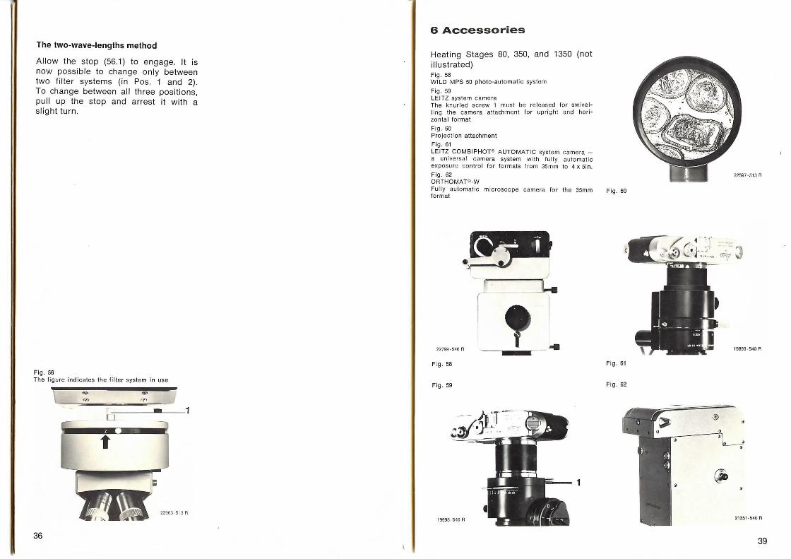
Fi g. 51 PLOEMOPAK 2.4 on the 0/ALUX 20
1 Lamp Housing 102 Z 2 Lamp holder 3 Cent rin g sc rews for the field diaphragm 4 Field diaphragm 5 Exci ting light suppression 6 Slot for addi tional suppression fi lters
Clamp ing dev ice of the switch lever for the two-wave-lengths method
8 Chanqing lever fo r the exc iting-fi l ter systems 9 PLOEMOPAK 2.4
--1
34
~ 6 7
8 9
22670 ·5 12 A
Exchanging the filter systems
Fig. 52 Open ing the cover of the PLOEMOPAK 2.4 housing for changing the filter system.
'
22977-513 A
Fi g. 53 PLOEMOPAK 2.4 with the hous ing cover removed and key (arrow) for releas ing the filter system.
22978-513 A
Fig . 54 Releasing the filter system.
22979·513 A
Fig . 55 Taking out the fi lter system.
35
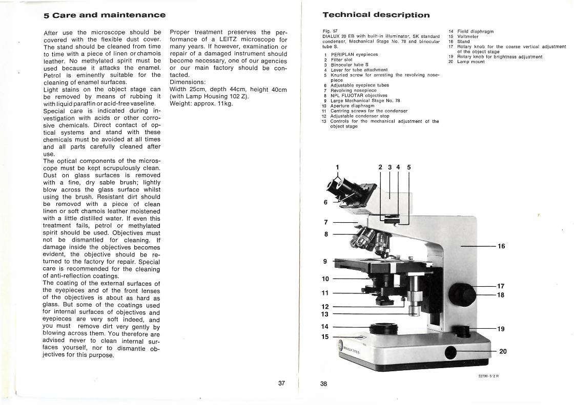
The two-wave-lengths method
Allow the stop (56.1) to engage. lt is now possible to change only between two filter systems (in Pos . 1 and 2) . To change between all three positions, pull up the stop and arrest it with a slight turn .
Fig. 56 The figure indicates the filter system in use
36
6 Accessories
Heating Stages 80, 350, and 1350 (not illustrated) Fig . 58 WILD MPS so photo-automatic system
Fig. 59 LEITZ system camera Th e knurled sc rew 1 must be released for swivelling the camera attachment for upright and hori zon tal format
Fig. 60 Projection attachment
Fig. 61 LEITZ COMBIPHOT" AUTOMATIC system camera -a universa l camera system with fully automatic exposure control for formats from 35mm to 4 x Sin. Fig. 62 ORTHOMAT" -W Fully automatic microscope camera for the 35mm format
_____ """"'! )
_=-:1-. I r
22799-540 A ---.-- ... Fig. 58
Fig. 59
1
Fig. 60
=-~~~~,.~~~--- ¥·~
19693-540 A
Fig. 61
Fig. 62
39
5 Care and maintenance
After use the microscope should be covered with the flexible dust cover. The stand should be cleaned from time to time with a piece of linen or chamois leather. No methylated spirit must be used because it attacks the enamel. Petrol is eminently suitable for the cleaning of enamel surfaces. Light stains on the object stage can be removed by means of rubbing it with liquid paraffin or acid-free vaseline. Special care is indicated during investigat ion with acids or other corrosive chemicals . Direct contact of optical systems and stand with these chemicals must be avoided at all times and all parts carefully cleaned after use. The optical components of the microscope must be kept scrupulously clean. Dust on glass surfaces is removed with a fine , dry sable brush; lightly blow across the glass surface whilst using the brush . Resistant dirt should be removed with a piece of clean linen or soft chamois leather moistened with a little distilled water. If even this treatment fails , petrol or methylated spirit should be used. Objectives must not be dismantled for cleaning. If damage inside the objectives becomes evident, the objective should be returned to the factory for repair. Special care is recommended for the cleaning of anti-reflection coatings. The coating of the external surfaces of the eyepieces and of the front lenses of the objectives is about as hard as glass. But some of the coatings used for internal surfaces of objectives and eyepieces are very soft indeed, and you must remove dirt very gently by blowing ac ross them. You therefore are advised never to clean internal surfaces yourself, nor to dismantle objectives for this purpose.
Proper treatment preserves the performance of a LEITZ microscope for many years. If however, examination or repair of a damaged instrument should become necessary, one of our agencies or our main factory should be contacted. Dimensions : Width 25cm, depth 44cm, height 40cm (with Lamp Housing 102 Z) . Weight : approx. 11 kg.
37
Technical description
Fig. 57 DIALUX 20 EB wi th bui lt-in illuminato r, SK standard cond ense r, Mechani ca l Stage No. 78 and bin oc ul ar tube S.
1 PERIPLAN eyepieces 2 Filter slot 3 Binocular tube S 4 Lever for tube attach ment 5 Knur led screw for arres ting the revo lving nose-
piece 6 Ad j ustab le eyepi ece tubes 7 Revo lving nosepiece 8 NPL FLUOTAR obj ectives 9 Large Mechanica l Stage No . 78
10 Aperture diaphrag m 11 Centri ng screws fo r the condenser 12 Ad justable condenser stop 13 Contro ls for the mechani ca l adj ustment of the
obj ect stag e
38
14 Field di aphrag m 15 Voltmeter 16 Stand 17 Rotary knob fo r the coarse verti cal ad justment
of the object stage 19 Rotary knob for brightness adjustment 20 Lamp mount
22709 ·512 R