Embed Size (px)
Citation preview

ROTR 110428ALS70_Overview_110428.ppt
Leica LIDAR SolutionsALS70 Product Line Overview
28 April 2011
ROTR 110428ALS70_Overview_110428.ppt
Content
What is LIDAR? What is ALS70? For customers considering upgrade from ALS60 For customers considering competing sensors

ROTR 110428ALS70_Overview_110428.ppt
ALS70 Product Line OverviewElements of a generic LIDAR system
ROTR 110428ALS70_Overview_110428.ppt
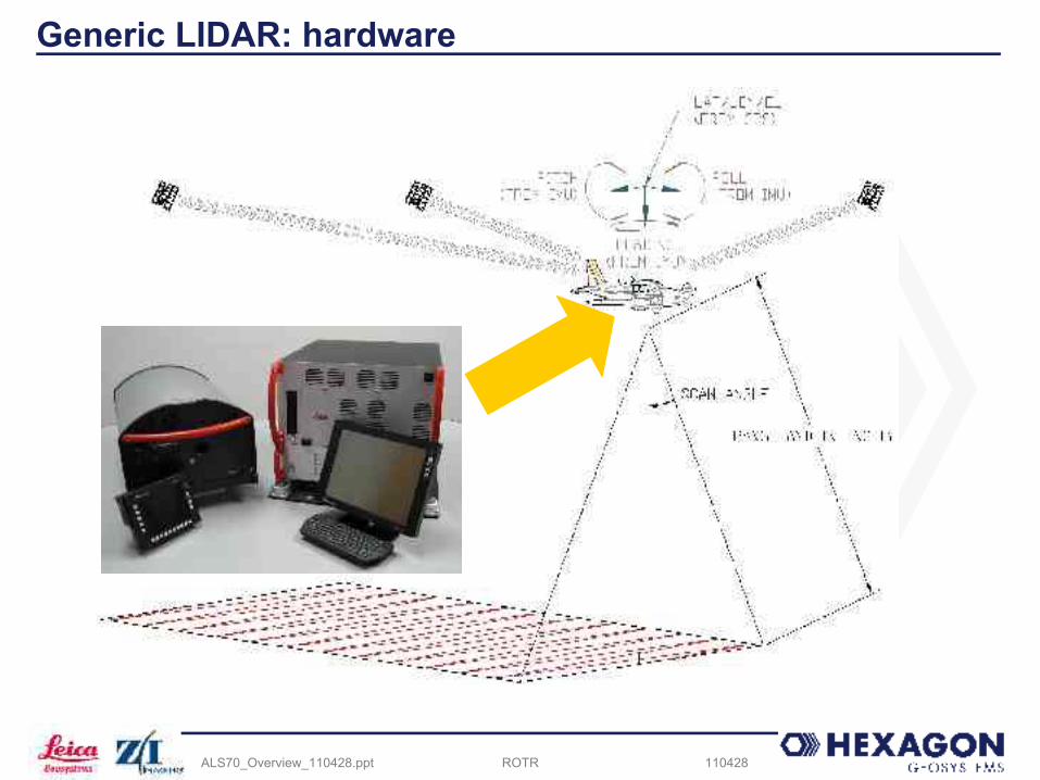
Generic LIDAR: hardware
ROTR 110428ALS70_Overview_110428.ppt
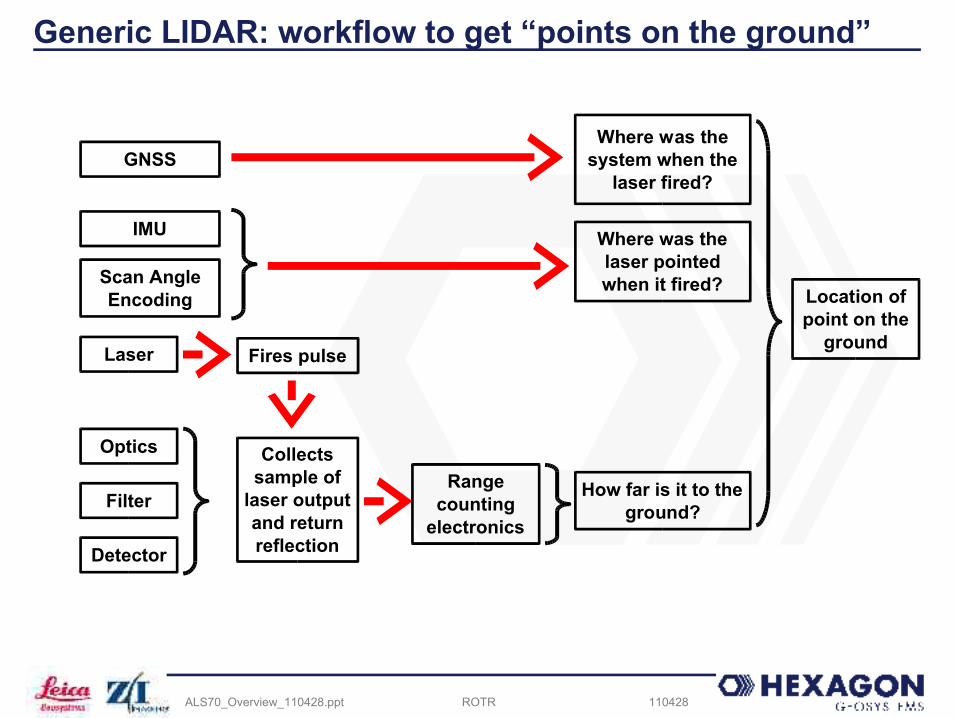
Generic LIDAR: workflow to get “points on the ground”
GNSS
IMU
Scan Angle Encoding
Range counting
electronics
Laser
Optics
Where was the system when the
laser fired?
Where was the laser pointed when it fired?
How far is it to the ground?
Location of point on the
groundFires pulse
Filter
Detector
Collects sample of
laser output and return reflection
ROTR 110428ALS70_Overview_110428.ppt
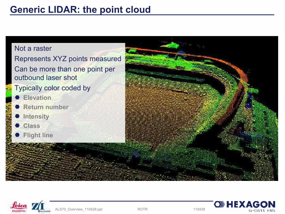
Generic LIDAR: the point cloud
Not a rasterRepresents XYZ points measuredCan be more than one point per outbound laser shotTypically color coded by Elevation Return number Intensity Class Flight line

ROTR 110428ALS70_Overview_110428.ppt
ALS70 Product Line OverviewWhat is ALS70?
ROTR 110428ALS70_Overview_110428.ppt
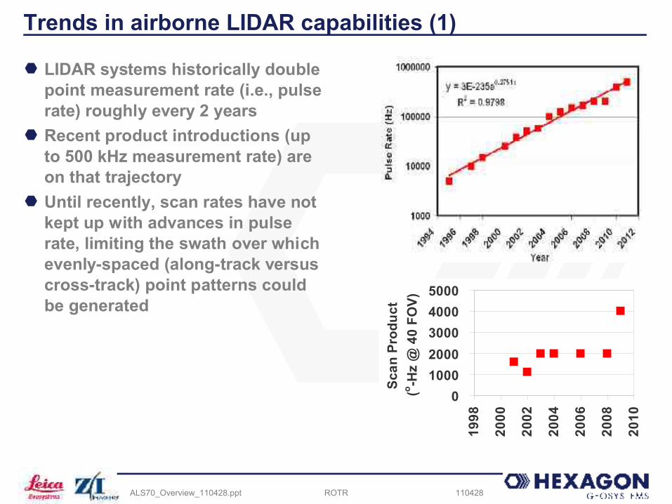
Trends in airborne LIDAR capabilities (1)
LIDAR systems historically double point measurement rate (i.e., pulse rate) roughly every 2 years
Recent product introductions (up to 500 kHz measurement rate) are on that trajectory
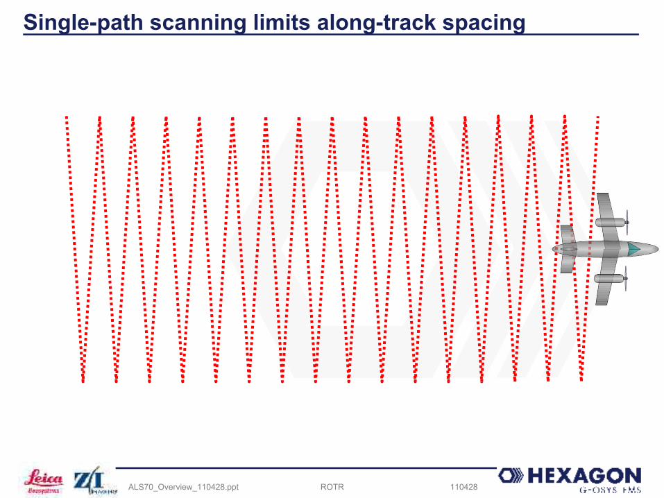
Until recently, scan rates have not kept up with advances in pulse rate, limiting the swath over which evenly-spaced (along-track versus cross-track) point patterns could be generated
010002000300040005000
1998
2000
2002
2004
2006
2008
2010
Scan
Pro
duct
(o -Hz
@ 4
0 FO
V)
ROTR 110428ALS70_Overview_110428.ppt
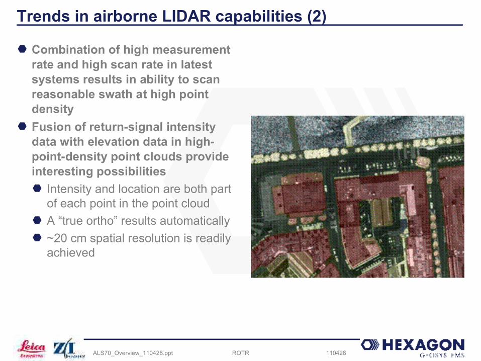
Trends in airborne LIDAR capabilities (2)
Combination of high measurement rate and high scan rate in latest systems results in ability to scan reasonable swath at high point density
Fusion of return-signal intensity data with elevation data in high-point-density point clouds provide interesting possibilities Intensity and location are both part
of each point in the point cloud A “true ortho” results automatically ~20 cm spatial resolution is readily
achieved
ROTR 110428ALS70_Overview_110428.ppt
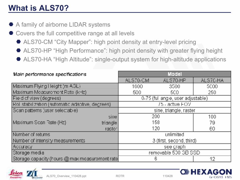
What is ALS70?
A family of airborne LIDAR systems Covers the full competitive range at all levels
ALS70-CM “City Mapper”: high point density at entry-level pricing ALS70-HP “High Performance”: high point density with greater flying height ALS70-HA “High Altitude”: single-output system for high-altitude applications
ROTR 110428ALS70_Overview_110428.ppt
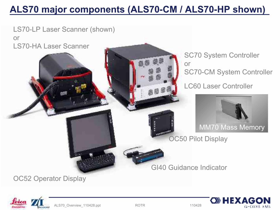
ALS70 major components (ALS70-CM / ALS70-HP shown)
LS70-LP Laser Scanner (shown)orLS70-HA Laser Scanner
SC70 System ControllerorSC70-CM System Controller
LC60 Laser Controller
OC50 Pilot Display
GI40 Guidance IndicatorOC52 Operator Display
MM70 Mass Memory
ROTR 110428ALS70_Overview_110428.ppt
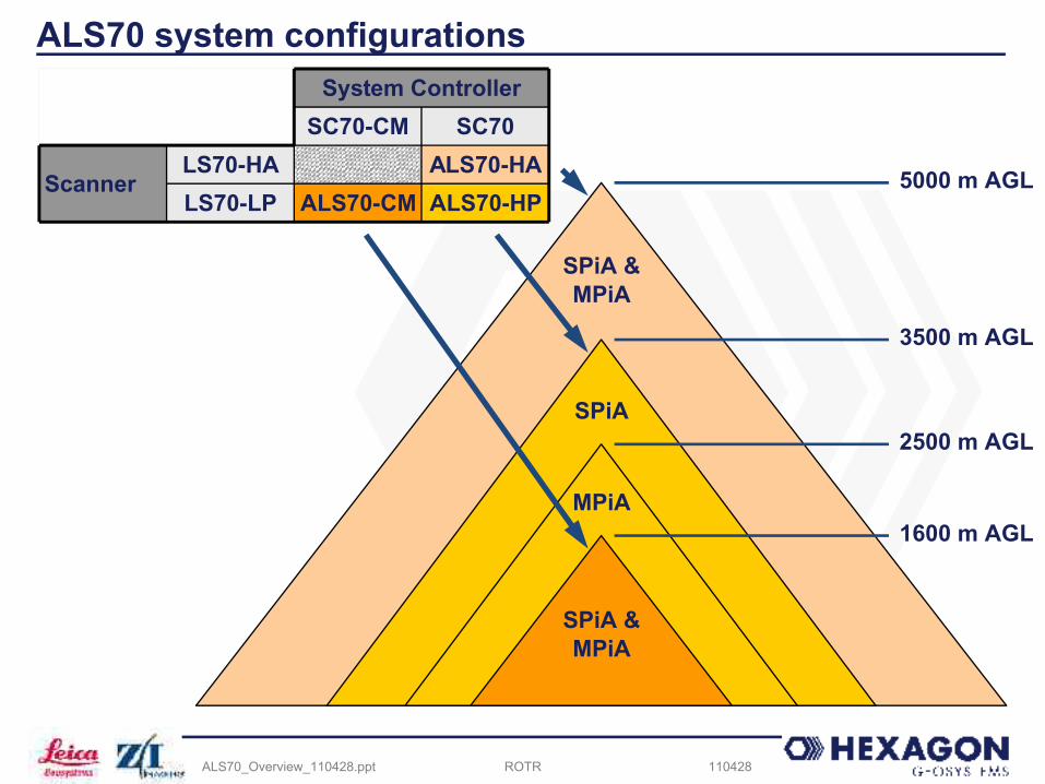
ALS70 system configurations
LS70-LPLS70-HA
SC70SC70-CM
ALS70-HPALS70-CMALS70-HA
Scanner
System Controller
MPiA
SPiA
SPiA & MPiA
SPiA & MPiA
5000 m AGL
3500 m AGL
2500 m AGL
1600 m AGL
ROTR 110428ALS70_Overview_110428.ppt
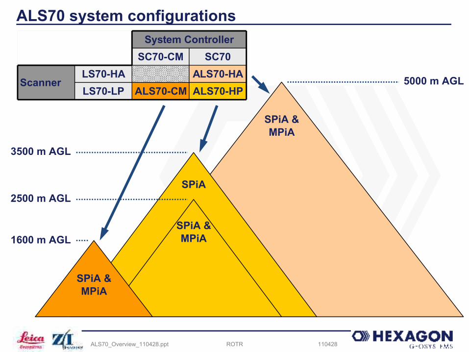
ALS70 system configurations
LS70-LPLS70-HA
SC70SC70-CM
ALS70-HPALS70-CMALS70-HA
Scanner
System Controller
SPiA & MPiA
SPiA
SPiA & MPiA
SPiA & MPiA
5000 m AGL
3500 m AGL
2500 m AGL
1600 m AGL

ROTR 110428ALS70_Overview_110428.ppt
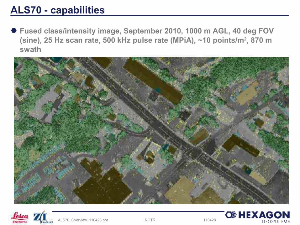
ALS70 - capabilities
Intensity image, 11 Mar 2011, 2300 m AGL, 40 deg FOV (sine), 25 Hz scan rate, 119 kHz pulse rate (MPiA), installed on PAV80 mount, 2 points/m2 (~70 cm post spacing)
ROTR 110428ALS70_Overview_110428.ppt
ALS70 - capabilities
Fused class/intensity image, September 2010, 1000 m AGL, 40 deg FOV (sine), 25 Hz scan rate, 500 kHz pulse rate (MPiA), ~10 points/m2, 870 m swath

ROTR 110428ALS70_Overview_110428.ppt
Major new technologies in ALS70
Point Density Multiplier – doubling productivity New range counting circuitry
Low electronic “overhead”, allowing pulse rates closer to the “speed of light” limit for given flying height (all models)
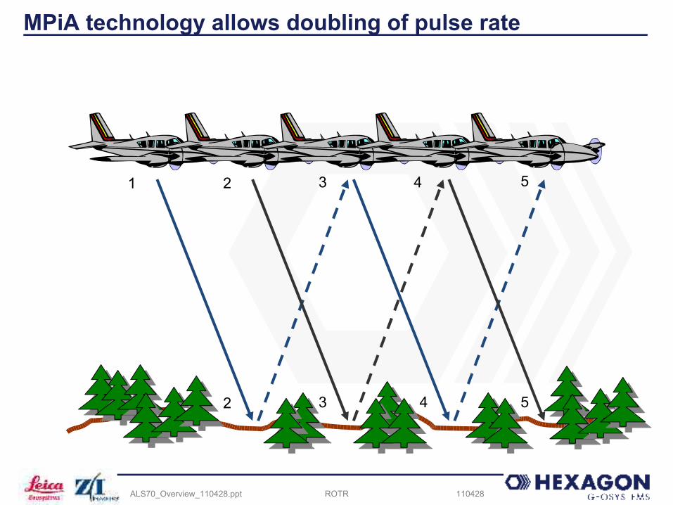
25% reduction in number of PCBs Dual-output scanner (ALS70-CM and ALS70-HP only) doubles effective pulse rate
and scan rate Single laser Single galvanometer scanner Single receiver optics Laser output split into two beams (slight forward and slight rearward look
angle) Dual receivers Autoscan feature monitors flying height and speed over round and adjusts
scan rate to help to keep scan patterns out-of-phase with one another (see separate ppt for details)
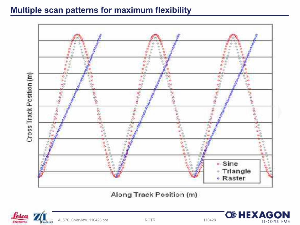
Multiple scan patterns (sine, triangle and raster) for greater flexibility in point pattern on ground
Increased receiver bandwidth and dynamic range, for better detection of small and/or low-reflectivity surfaces (e.g., power lines, fresh asphalt)
ROTR 110428ALS70_Overview_110428.ppt
Single-path scanning limits along-track spacing

ROTR 110428ALS70_Overview_110428.ppt
Dual-output scanning doubles scan rate, pulse rate

ROTR 110428ALS70_Overview_110428.ppt
SPiA technology limits pulse rate
1 3 5
2 4
ROTR 110428ALS70_Overview_110428.ppt
MPiA technology allows doubling of pulse rate
1 3
3
52
2
4
4 5
ROTR 110428ALS70_Overview_110428.ppt
Multiple scan patterns for maximum flexibility

ROTR 110428ALS70_Overview_110428.ppt
ALS70 family – additional features
Laser features consistent pulse shape over wide range of pulse rates for high range accuracy/low range jitter
High-accuracy scan angle encoder preserves planimetric accuracy as altitude increases
Powerful galvanometer scanner Allows use of large-aperture optics Scans fast at any given FOV, allowing:
Small along-track spacing in fixed wing aircraft Balanced along-track and cross-track (very important when using high
pulse rates and/or higher-speed aircraft) Allows widest available FOV and greatest roll compensation range
3 AUX sensor ports for connection of additional devices e.g., RCD30, infrared imagers, hyperspectral, etc. Provides 1 PPS pulse, trigger output, MEP inputs, LAN connections Limited power available (unfiltered 28 VDC)

ROTR 110428ALS70_Overview_110428.ppt
ALS70 family – mounting configurations (ALS70-CM/HP shown)
ALS only
ALS with / without RCD, Dart pod
ALS with / without RCD on PAV80
ALS with / without RCD, low profile
In pod
In cabin
ROTR 110428ALS70_Overview_110428.ppt
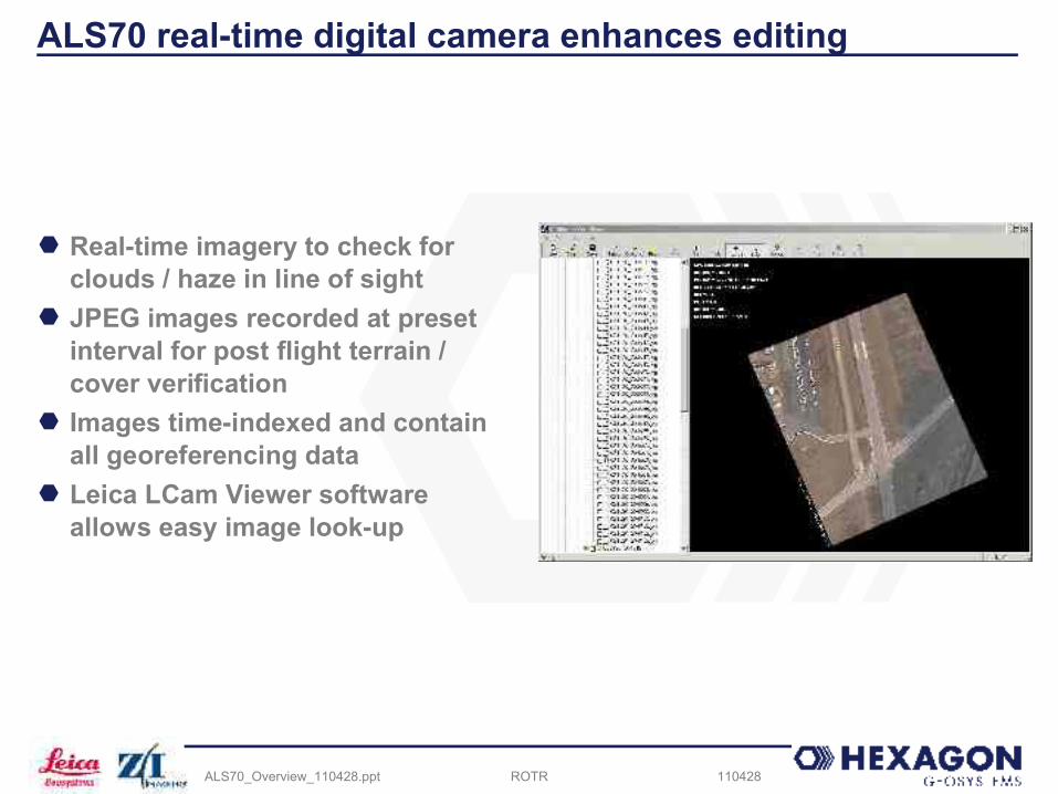
ALS70 real-time digital camera enhances editing
Real-time imagery to check for clouds / haze in line of sight
JPEG images recorded at preset interval for post flight terrain / cover verification
Images time-indexed and contain all georeferencing data
Leica LCam Viewer software allows easy image look-up
ROTR 110428ALS70_Overview_110428.ppt
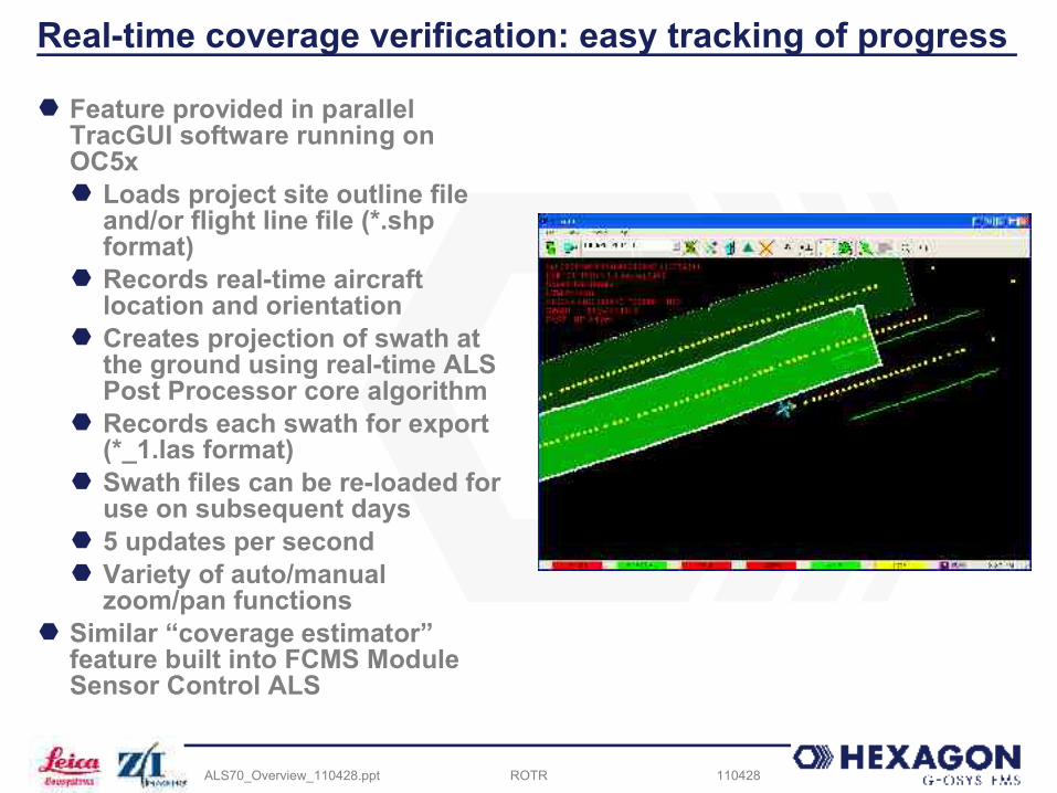
Real-time coverage verification: easy tracking of progress
Feature provided in parallel TracGUI software running on OC5x Loads project site outline file
and/or flight line file (*.shp format)
Records real-time aircraft location and orientation
Creates projection of swath at the ground using real-time ALS Post Processor core algorithm
Records each swath for export (*_1.las format)
Swath files can be re-loaded for use on subsequent days
5 updates per second Variety of auto/manual
zoom/pan functions Similar “coverage estimator”
feature built into FCMS Module Sensor Control ALS
ROTR 110428ALS70_Overview_110428.ppt
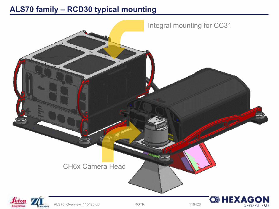
ALS70 family – RCD30 typical mounting
CH6x Camera Head
Integral mounting for CC31
ROTR 110428ALS70_Overview_110428.ppt
ALS70 Product Line OverviewALS70 Workflow

ROTR 110428ALS70_Overview_110428.ppt
ALS70 workflow: planning to point cloud under one roofPlanning Collection Ground Processing
FPES
AeroPlan70
FCMS
IPAS TC
IPAS CO
IPAS BST
ALSpp

ROTR 110428ALS70_Overview_110428.ppt
ALS70 workflow
FPES / AeroPlan70
Mission Planning
modealtitudescan rateFOVflight speedflight linesflight height
record DGPS base station data
Airborne Operations
record position and attitude data•GPS•IMU
record scanner data•range•scan angle•intensity•timing info
extract position
and attitude
data
DGNSS processing
trajectoryprocessing
•point cloud generation•output formatting – LDI, LAS, ASCII•projection - WGS 84, UTM, state plane, Swiss, TW 97, user- supplied•datum (state plane only) - NGVD 29, NAVD 88
•tiling•coverage verification•outlier removal•bare earth•thinning•catenary generation
deliverables
Ground Operations
Planning Collection Processing
real-time nav file
*.SCN raw scanner files
ALS, FCMS
IPAS TC IPAS TC
ALS Post Processor
position and
attitude file
GPS
TerraScan
IPAS TC
MicroStation
•TIN/contour•control report
TerraModeller
laser boresitecalibration
Attune
“LAS” file
ROTR 110428ALS70_Overview_110428.ppt
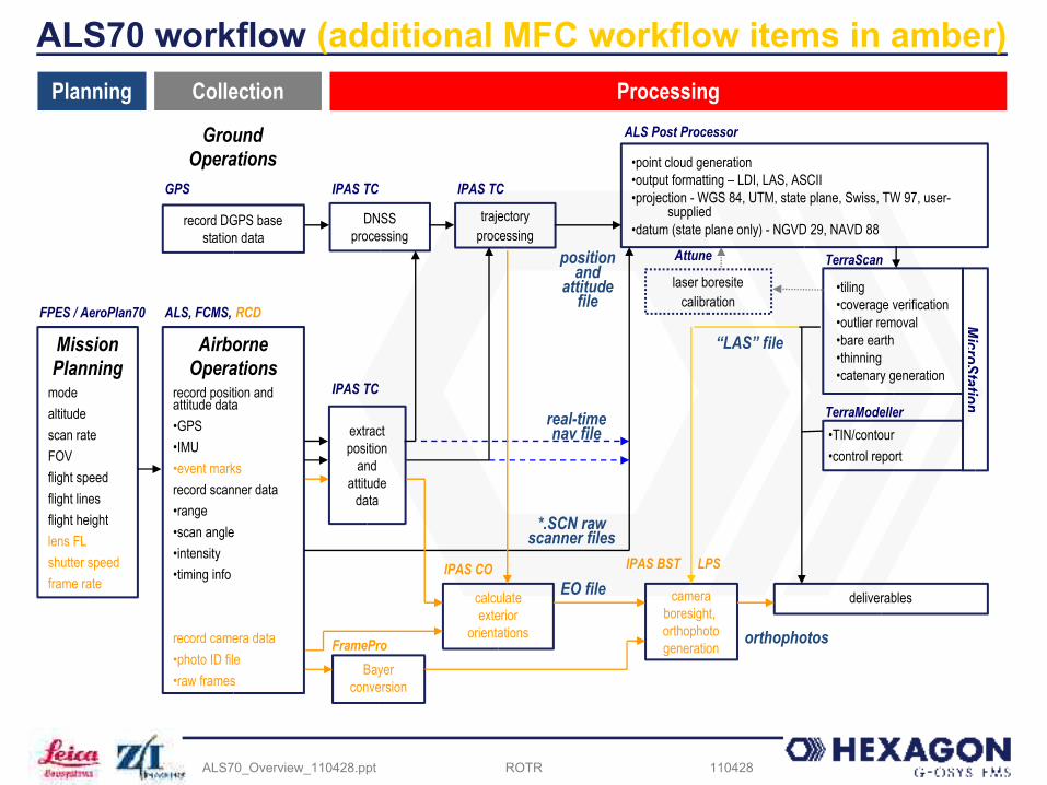
ALS70 workflow (additional MFC workflow items in amber)
FPES / AeroPlan70
Mission Planning
modealtitudescan rateFOVflight speedflight linesflight heightlens FLshutter speedframe rate
record DGPS base station data
Airborne Operations
record position and attitude data•GPS•IMU•event marksrecord scanner data•range•scan angle•intensity•timing info
record camera data•photo ID file•raw frames
extract position
and attitude
data
DNSS processing
trajectoryprocessing
•point cloud generation•output formatting – LDI, LAS, ASCII•projection - WGS 84, UTM, state plane, Swiss, TW 97, user- supplied•datum (state plane only) - NGVD 29, NAVD 88
•tiling•coverage verification•outlier removal•bare earth•thinning•catenary generation
deliverables
Ground Operations
Planning Collection Processing
real-time nav file
*.SCN raw scanner files
ALS, FCMS, RCD
IPAS TC IPAS TC
ALS Post Processor
position and
attitude file
GPS
TerraScan
IPAS TC
MicroStation
•TIN/contour•control report
TerraModeller
laser boresitecalibration
Attune
calculate exterior
orientations
EO fileIPAS CO
camera boresight, orthophoto generation
IPAS BST
“LAS” file
orthophotos
Bayer conversion
FramePro
LPS
ROTR 110428ALS70_Overview_110428.ppt
ALS70 Product Line OverviewALS70 versus ALS60

ROTR 110428ALS70_Overview_110428.ppt
For those considering ALS60-CM to ALS70-CM upgrade
Pulse rates ALS70-CM pulse rates 2.5x that of
ALS60-CM ALS70-CM has MPiA capability (not
available in ALS60-CM) ALS70-CM carries 500 kHz
performance to 1107 m AGL @ 40o FOV
ALS70-CM max AGL 1600 m versus 1000 m AGL for ALS60-CM
Scan Rates ALS70 sine rate ~2.0x ALS60 sine
rates New triangle scan pattern ~1.4x - 1.6x
ALS60 sine rates New raster scan pattern ~0.8x ALS60
sine rates
Mor
e pr
oduc
tivity
Bet
ter a
long
-trac
k sp
acin
g
ROTR 110428ALS70_Overview_110428.ppt
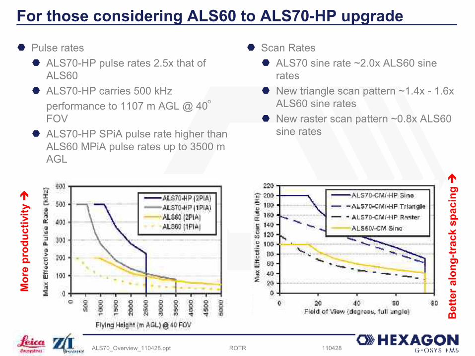
For those considering ALS60 to ALS70-HP upgrade
Pulse rates ALS70-HP pulse rates 2.5x that of
ALS60 ALS70-HP carries 500 kHz
performance to 1107 m AGL @ 40o FOV
ALS70-HP SPiA pulse rate higher than ALS60 MPiA pulse rates up to 3500 m AGL
Scan Rates ALS70 sine rate ~2.0x ALS60 sine
rates New triangle scan pattern ~1.4x - 1.6x
ALS60 sine rates New raster scan pattern ~0.8x ALS60
sine rates
Mor
e pr
oduc
tivity
Bet
ter a
long
-trac
k sp
acin
g
ROTR 110428ALS70_Overview_110428.ppt
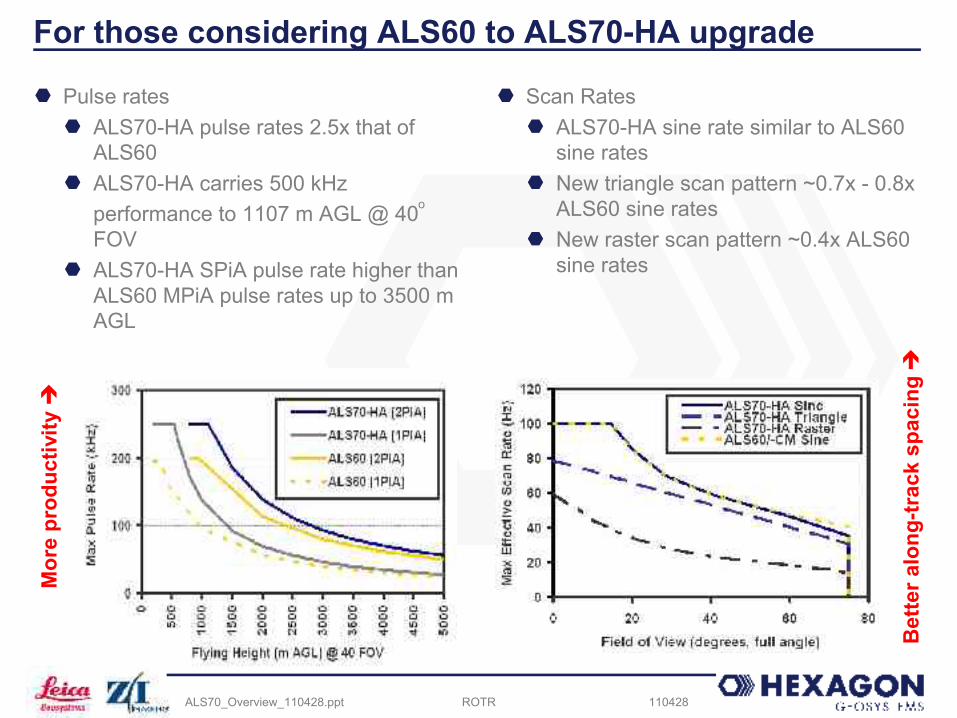
For those considering ALS60 to ALS70-HA upgrade
Pulse rates ALS70-HA pulse rates 2.5x that of
ALS60 ALS70-HA carries 500 kHz
performance to 1107 m AGL @ 40o FOV
ALS70-HA SPiA pulse rate higher than ALS60 MPiA pulse rates up to 3500 m AGL
Scan Rates ALS70-HA sine rate similar to ALS60
sine rates New triangle scan pattern ~0.7x - 0.8x
ALS60 sine rates New raster scan pattern ~0.4x ALS60
sine rates
Mor
e pr
oduc
tivity
Bet
ter a
long
-trac
k sp
acin
g

ROTR 110428ALS70_Overview_110428.ppt
Upgrading from ALS60 to ALS70
ROTR 110428ALS70_Overview_110428.ppt
ALS70 Product Line OverviewALS70 versus competing sensors
ROTR 110428ALS70_Overview_110428.ppt
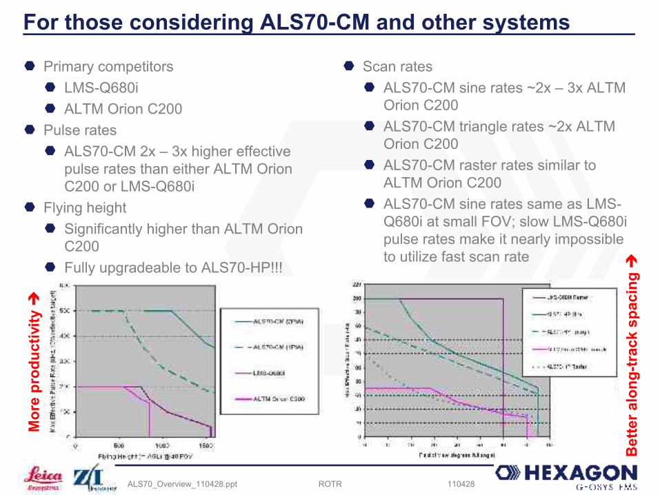
For those considering ALS70-CM and other systems
Primary competitors LMS-Q680i ALTM Orion C200
Pulse rates ALS70-CM 2x – 3x higher effective
pulse rates than either ALTM Orion C200 or LMS-Q680i
Flying height Significantly higher than ALTM Orion
C200 Fully upgradeable to ALS70-HP!!!
Scan rates ALS70-CM sine rates ~2x – 3x ALTM
Orion C200 ALS70-CM triangle rates ~2x ALTM
Orion C200 ALS70-CM raster rates similar to
ALTM Orion C200 ALS70-CM sine rates same as LMS-
Q680i at small FOV; slow LMS-Q680i pulse rates make it nearly impossible to utilize fast scan rate
Mor
e pr
oduc
tivity
Bet
ter a
long
-trac
k sp
acin
g
ROTR 110428ALS70_Overview_110428.ppt
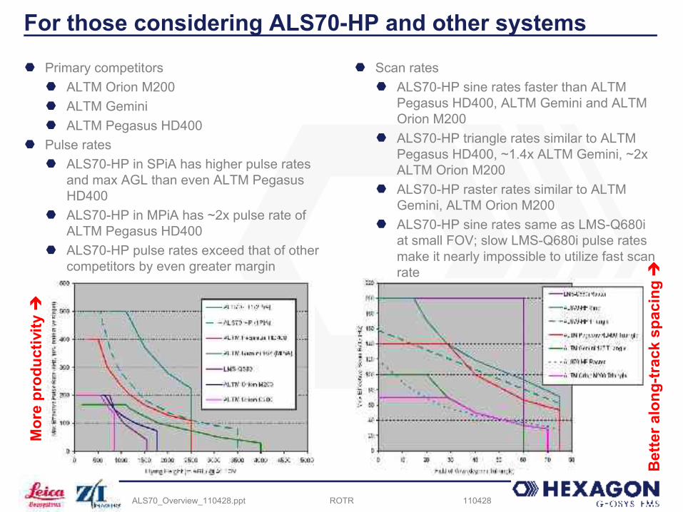
For those considering ALS70-HP and other systems
Primary competitors ALTM Orion M200 ALTM Gemini ALTM Pegasus HD400
Pulse rates ALS70-HP in SPiA has higher pulse rates
and max AGL than even ALTM Pegasus HD400
ALS70-HP in MPiA has ~2x pulse rate of ALTM Pegasus HD400
ALS70-HP pulse rates exceed that of other competitors by even greater margin
Scan rates ALS70-HP sine rates faster than ALTM
Pegasus HD400, ALTM Gemini and ALTM Orion M200
ALS70-HP triangle rates similar to ALTM Pegasus HD400, ~1.4x ALTM Gemini, ~2x ALTM Orion M200
ALS70-HP raster rates similar to ALTM Gemini, ALTM Orion M200
ALS70-HP sine rates same as LMS-Q680i at small FOV; slow LMS-Q680i pulse rates make it nearly impossible to utilize fast scan rate
Mor
e pr
oduc
tivity
Bet
ter a
long
-trac
k sp
acin
g

ROTR 110428ALS70_Overview_110428.ppt
For those considering ALS70-HA and other systems
Primary competitors ALTM Orion M200 ALTM Gemini ALTM Pegasus HD400
Pulse rates ALS70-HA in MPiA has higher pulse
rates and max AGL than ALTM Pegasus HD400 above 1000 m AGL and ALTM Gemini at all altitudes
ALS70-HA in SPiA has higher pulse rate than ALTM Orion M200
Max AGL greater than all competitors
Scan rates ALS70-HA sine rates faster than ALTM
Gemini and ALTM Orion M200 over most FOVs
ALS70-HA triangle rates similar to ALTM Orion M200
ALS70-HA raster pattern not available on ALTM Pegasus HD400, ALTM Gemini or ALTM Orion M200
Raster scan pattern is ideal for the larger post spacing typical for high-AGL acquisition
Mor
e pr
oduc
tivity
Bet
ter a
long
-trac
k sp
acin
g

ROTR 110428ALS70_Overview_110428.ppt
Thank you!
ROTR 110428ALS70_Overview_110428.ppt
ALS70 Product Line OverviewAppendix 1 – 12-bit intensity versus ALS70-HP
ROTR 110428ALS70_Overview_110428.ppt
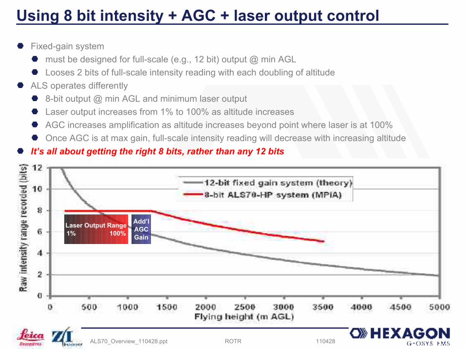
Using 8 bit intensity + AGC + laser output control
Fixed-gain system must be designed for full-scale (e.g., 12 bit) output @ min AGL Looses 2 bits of full-scale intensity reading with each doubling of altitude
ALS operates differently 8-bit output @ min AGL and minimum laser output Laser output increases from 1% to 100% as altitude increases AGC increases amplification as altitude increases beyond point where laser is at 100% Once AGC is at max gain, full-scale intensity reading will decrease with increasing altitude
It’s all about getting the right 8 bits, rather than any 12 bits
Laser Output Range1% 100%
Add’l AGCGain

ROTR 110428ALS70_Overview_110428.ppt
ALS70 Product Line OverviewAppendix 2 – Accuracy plots
ROTR 110428ALS70_Overview_110428.ppt
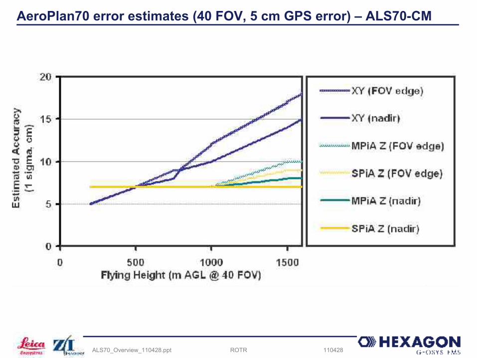
AeroPlan70 error estimates (40 FOV, 5 cm GPS error) – ALS70-CM

ROTR 110428ALS70_Overview_110428.ppt
AeroPlan70 error estimates (40 FOV, 5 cm GPS error) – ALS70-HP
ROTR 110428ALS70_Overview_110428.ppt
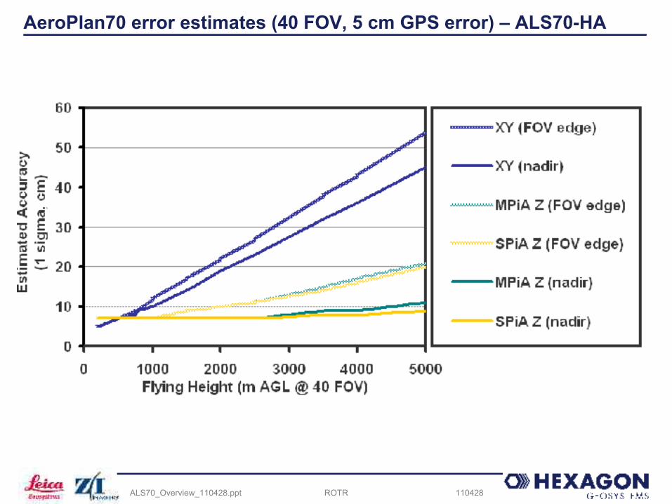
AeroPlan70 error estimates (40 FOV, 5 cm GPS error) – ALS70-HA