Embed Size (px)
Citation preview
Leica CS10/CS15 & GS SensorsUser Manual
Version 5.0English

2CS10/CS15 & GS Sensors, Introduction
IntroductionPurchase Congratulations on the purchase of a Leica SmartWorx Viva instrument.
This manual contains important safety directions as well as instructions for setting up the product and operating it. Refer to "5 Safety Directions" for further informa-tion.Read carefully through the User Manual before you switch on the product.
Product identifica-tion
The type and serial number of your product are indicated on the type plate.Enter the type and serial number in your manual and always refer to this information when you need to contact your agency or Leica Geosystems authorised service work-shop.
Type: _______________
Serial No.: _______________
CS10/CS15 & GS Sensors, Introduction 3
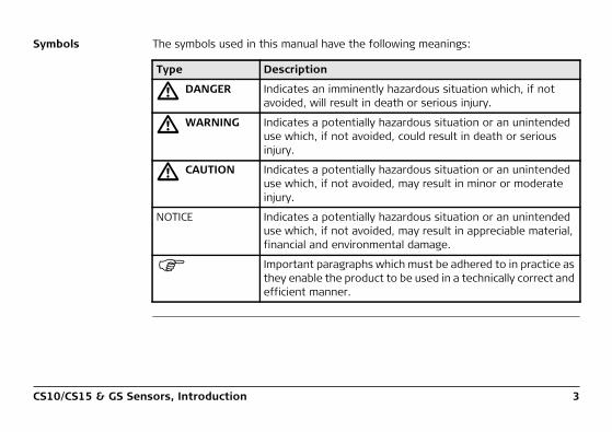
Symbols The symbols used in this manual have the following meanings:
Type Description
� DANGER Indicates an imminently hazardous situation which, if not avoided, will result in death or serious injury.
� WARNING Indicates a potentially hazardous situation or an unintended use which, if not avoided, could result in death or serious injury.
� CAUTION Indicates a potentially hazardous situation or an unintended use which, if not avoided, may result in minor or moderate injury.
NOTICE Indicates a potentially hazardous situation or an unintended use which, if not avoided, may result in appreciable material, financial and environmental damage.
Important paragraphs which must be adhered to in practice as they enable the product to be used in a technically correct and efficient manner.

4CS10/CS15 & GS Sensors, Introduction
Trademarks • Windows is a registered trademark of Microsoft Corporation in the United States and other countries
• CompactFlash and CF are trademarks of SanDisk Corporation• Bluetooth is a registered trademark of Bluetooth SIG, Inc.• SD is a trademark of the SD Card AssociationAll other trademarks are the property of their respective owners.
Validity of this manual
This manual applies to the CS10/CS15, GS05/GS06, GS08plus/GS12 and CTR16 instru-ments. Differences between the various models are marked and described.
CS10/CS15 & GS Sensors, Introduction 5
Availabledocumentation
Name Description/Format
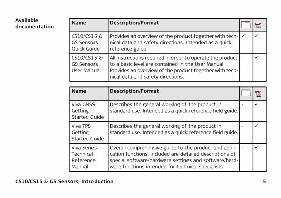
CS10/CS15 & GS Sensors Quick Guide
Provides an overview of the product together with tech-nical data and safety directions. Intended as a quick reference guide.
CS10/CS15 & GS Sensors User Manual
All instructions required in order to operate the product to a basic level are contained in the User Manual. Provides an overview of the product together with tech-nical data and safety directions.
-
Name Description/Format
Viva GNSS Getting Started Guide
Describes the general working of the product in standard use. Intended as a quick reference field guide.
-
Viva TPS Getting Started Guide
Describes the general working of the product in standard use. Intended as a quick reference field guide.
-
Viva Series Technical Reference Manual
Overall comprehensive guide to the product and appli-cation functions. Included are detailed descriptions of special software/hardware settings and software/hard-ware functions intended for technical specialists.
-

6CS10/CS15 & GS Sensors, Introduction
Refer to the following resources for all CS10/CS15 & GS Sensor documenta-tion/software:• the Leica Viva Series DVD• https://myworld.leica-geosystems.com
myWorld@Leica Geosystems (https://myworld.leica-geosystems.com) offers a wide range of services, information and training material.With direct access to myWorld, you are able to access all relevant services whenever it is convenient for you, 24 hours a day, 7 days per week. This increases your effi-ciency and keeps you and your equipment instantly updated with the latest informa-tion from Leica Geosystems.
Service Description
myProducts Simply add all Leica Geosystems products that you and your company own. View detailed information on your products, buy additional options or Customer Care Packages (CCPs), update your products with the latest software and keep up-to-date with the latest documentation.
myService View the service history of your products in Leica Geosystems Service Centers and detailed information on the services performed on your products. For your products that are currently in Leica Geosystems Service Centers view the current service status and the expected end date of service.

CS10/CS15 & GS Sensors, Introduction 7
mySupport Create new support requests for your products that will be answered by your local Leica Geosystems Support Team. View the complete history of your Support and view detailed information on each request in case you want to refer to previous support requests.
myTraining Enhance your product knowledge with the Leica Geosystems Campus - Information, Knowledge, Training. Study the latest online training material or download training material on your products. Keep up-to-date with the latest News on your products and register for Seminars or Courses in your country.
Service Description
8CS10/CS15 & GS Sensors, Table of Contents
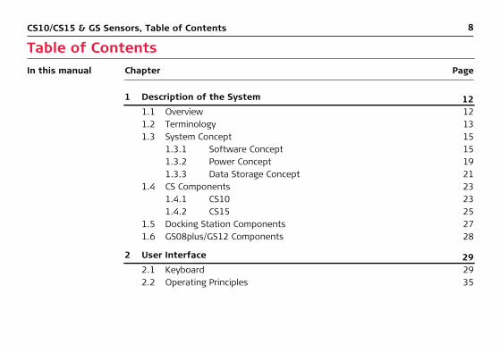
Table of ContentsIn this manual Chapter Page
1 Description of the System 121.1 Overview 121.2 Terminology 131.3 System Concept 15
1.3.1 Software Concept 151.3.2 Power Concept 191.3.3 Data Storage Concept 21
1.4 CS Components 231.4.1 CS10 231.4.2 CS15 25
1.5 Docking Station Components 271.6 GS08plus/GS12 Components 28
2 User Interface 292.1 Keyboard 292.2 Operating Principles 35
CS10/CS15 & GS Sensors, Table of Contents 9
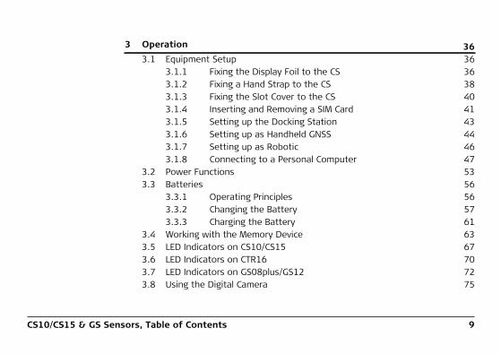
3 Operation 363.1 Equipment Setup 36
3.1.1 Fixing the Display Foil to the CS 363.1.2 Fixing a Hand Strap to the CS 383.1.3 Fixing the Slot Cover to the CS 403.1.4 Inserting and Removing a SIM Card 413.1.5 Setting up the Docking Station 433.1.6 Setting up as Handheld GNSS 443.1.7 Setting up as Robotic 463.1.8 Connecting to a Personal Computer 47
3.2 Power Functions 533.3 Batteries 56
3.3.1 Operating Principles 563.3.2 Changing the Battery 573.3.3 Charging the Battery 61
3.4 Working with the Memory Device 633.5 LED Indicators on CS10/CS15 673.6 LED Indicators on CTR16 703.7 LED Indicators on GS08plus/GS12 723.8 Using the Digital Camera 75

10CS10/CS15 & GS Sensors, Table of Contents
4 Care and Transport 774.1 Transport 774.2 Storage 784.3 Cleaning and Drying 79
5 Safety Directions 815.1 General Introduction 815.2 Definition of Use 825.3 Limits of Use 845.4 Responsibilities 855.5 Hazards of Use 865.6 Electromagnetic Compatibility EMC 945.7 FCC Statement, Applicable in U.S. 97
6 Technical Data 1026.1 CS10/CS15 Technical Data 1026.2 GS05/GS06 Technical Data 107
6.2.1 Tracking Characteristics 1076.2.2 Accuracy 1096.2.3 Technical Data 110
6.3 CTR16 Technical Data 1136.4 GS08plus/GS12 115
CS10/CS15 & GS Sensors, Table of Contents 11
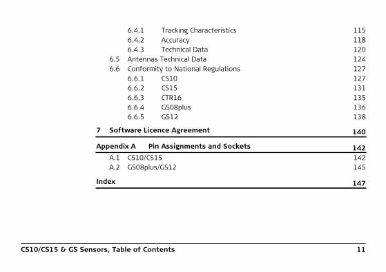
6.4.1 Tracking Characteristics 1156.4.2 Accuracy 1186.4.3 Technical Data 120
6.5 Antennas Technical Data 1246.6 Conformity to National Regulations 127
6.6.1 CS10 1276.6.2 CS15 1316.6.3 CTR16 1356.6.4 GS08plus 1366.6.5 GS12 138
7 Software Licence Agreement 140
Appendix A Pin Assignments and Sockets 142A.1 CS10/CS15 142A.2 GS08plus/GS12 145
Index 147

12CS10/CS15 & GS Sensors, Description of the System
1 Description of the System1.1 Overview
System compo-nents
003982_001 CS10 GS12
GS08plus
CS15
GS05 GS06
CTR16

CS10/CS15 & GS Sensors, Description of the System 13
1.2 Terminology
CS general descrip-tion
CS is a collective term describing the various models (CS10/CS15) of the multi-purpose field controller which is used with GNSS and TPS instruments.
CS available models
*1 removable
Mod
el
Touc
h sc
reen
Colo
ur d
ispl
ay
Inte
rnal
rad
io
mod
em
Inte
rnal
3.5
GSM
/U
MTS
mod
em
Inte
rnal
bat
tery
*1
SD c
ard
Com
pact
Flas
h ca
rd
Blue
toot
h
Wir
eles
s LA
N80
2.11
b/g
Win
dow
s CE
Basic (CS10/CS15) - - -
Radio (CS10) -
3.5G (CS10/CS15) -
Use the supplied stylus on the screens of the touch screen.

14CS10/CS15 & GS Sensors, Description of the System
CS available radios Radios for remote control (RCS) are available in the following variations:
Type Description
CS10 with internal radio
Field controller with an integrated radio modem. This field controller has a colour display.
CS15 with CTR16, no internal radio
Field controller without integrated radio modem. A high perfor-mance wireless data transfer device (CTR16) can be attached. The field controller has a colour display.

CS10/CS15 & GS Sensors, Description of the System 15
1.3 System Concept1.3.1 Software Concept
Software for all CS models
Software for the GS05/GS06
Software for the GS08plus/GS12
Software type Description
CS firmware This software includes:
(CS_xx.fw) - The language-specific version of Windows CE.
- The basic functionality of the CS.
Software type Description
GS firmware This software includes:
(GS_xx.fw) - The firmware for the measurement engine.
Software type Description
ME firmware This software includes:
(ME_xx.fw) - The firmware for the measurement engine.
16CS10/CS15 & GS Sensors, Description of the System
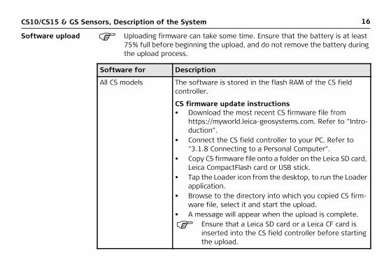
Software upload Uploading firmware can take some time. Ensure that the battery is at least 75% full before beginning the upload, and do not remove the battery during the upload process.
Software for Description
All CS models The software is stored in the flash RAM of the CS field controller.
CS firmware update instructions• Download the most recent CS firmware file from
https://myworld.leica-geosystems.com. Refer to "Intro-duction".
• Connect the CS field controller to your PC. Refer to "3.1.8 Connecting to a Personal Computer".
• Copy CS firmware file onto a folder on the Leica SD card, Leica CompactFlash card or USB stick.
• Tap the Loader icon from the desktop, to run the Loader application.
• Browse to the directory into which you copied CS firm-ware file, select it and start the upload.
• A message will appear when the upload is complete.
Ensure that a Leica SD card or a Leica CF card is inserted into the CS field controller before starting the upload.

CS10/CS15 & GS Sensors, Description of the System 17
GS05/GS06 The software is stored in the flash RAM of the GS05/GS06.
GS firmware update instructions• Download the most recent GS firmware file from
https://myworld.leica-geosystems.com. Refer to "Intro-duction".
• Connect the CS field controller to your PC. Refer to "3.1.8 Connecting to a Personal Computer".
• Copy GS firmware file into the /SYSTEM directory of the Leica SD card or Leica CompactFlash card.
• Connect the GS05/GS06 to the CS field controller. Refer to "3.1.6 Setting up as Handheld GNSS".
• Establish a connection between the GS05/GS06 and the CS field controller. Refer to the Leica Viva TechRef (Connections.. - GPS connection wizard).
• Start the upload. Refer to the Leica Viva GNSS Getting Started Guide (Appendix B Uploading System Files).
• A message will appear when the upload is complete.
Software for Description

18CS10/CS15 & GS Sensors, Description of the System
GS08plus/GS12 The software is stored in the flash RAM of the GS08plus/GS12.
ME firmware update instructions• Download the most recent ME firmware file from
https://myworld.leica-geosystems.com. Refer to "Intro-duction".
• Connect the CS field controller to your PC. Refer to "3.1.8 Connecting to a Personal Computer".
• Copy ME firmware file into the /SYSTEM directory of the Leica SD card or Leica CompactFlash card.
• Connect the GS08plus/GS12 with the GEV234/GEV237 cable to the CS field controller and establish a connec-tion between the GS08plus/GS12 and the CS field controller. Refer to the Leica Viva TechRef (Connections.. - GPS connection wizard).
• Start the upload. Refer to the Leica Viva GNSS Getting Started Guide (Appendix B Uploading System Files).
• A message will appear when the upload is complete.
Software for Description
CS10/CS15 & GS Sensors, Description of the System 19
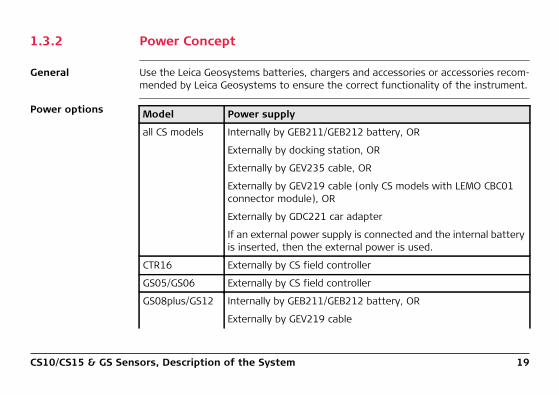
1.3.2 Power Concept
General Use the Leica Geosystems batteries, chargers and accessories or accessories recom-mended by Leica Geosystems to ensure the correct functionality of the instrument.
Power options Model Power supply
all CS models Internally by GEB211/GEB212 battery, OR
Externally by docking station, OR
Externally by GEV235 cable, OR
Externally by GEV219 cable (only CS models with LEMO CBC01 connector module), OR
Externally by GDC221 car adapter
If an external power supply is connected and the internal battery is inserted, then the external power is used.
CTR16 Externally by CS field controller
GS05/GS06 Externally by CS field controller
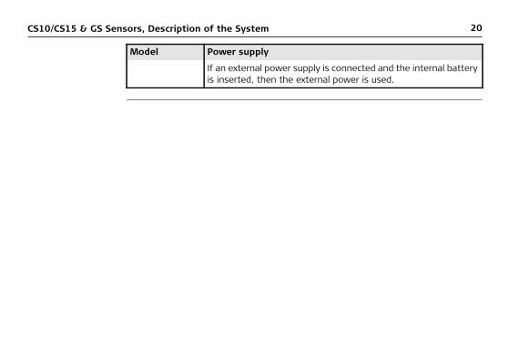
GS08plus/GS12 Internally by GEB211/GEB212 battery, OR
Externally by GEV219 cable
20CS10/CS15 & GS Sensors, Description of the System
If an external power supply is connected and the internal battery is inserted, then the external power is used.
Model Power supply
CS10/CS15 & GS Sensors, Description of the System 21
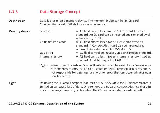
1.3.3 Data Storage Concept
Description Data is stored on a memory device. The memory device can be an SD card, CompactFlash card, USB stick or internal memory.
Memory device
While other SD cards or CompactFlash cards can be used, Leica Geosystems recommends to only use Leica SD cards or Leica CompactFlash cards and is not responsible for data loss or any other error that can occur while using a non-Leica card.
Removing the SD card, CompactFlash card or USB stick while the CS field controller is turned on can cause loss of data. Only remove the SD card, CompactFlash card or USB stick or unplug connecting cables when the CS field controller is switched off.
SD card: All CS field controllers have an SD card slot fitted as standard. An SD card can be inserted and removed. Avail-able capacity: 1 GB.
CompactFlash card: All CS field controllers have a CF card slot fitted as standard. A CompactFlash card can be inserted and removed. Available capacity: 256 MB, 1 GB.
USB stick: All CS field controllers have a USB port fitted as standard.Internal memory: All CS field controllers have an internal memory fitted as
standard. Available capacity: 1 GB.

22CS10/CS15 & GS Sensors, Description of the System
Transfer data Data can be transferred in various ways. Refer to "3.1.8 Connecting to a Personal Computer".
CompactFlash cards and SD cards can directly be used in an OMNI drive as supplied by Leica Geosystems. Other PC card drives can require an adaptor.
CS10/CS15 & GS Sensors, Description of the System 23
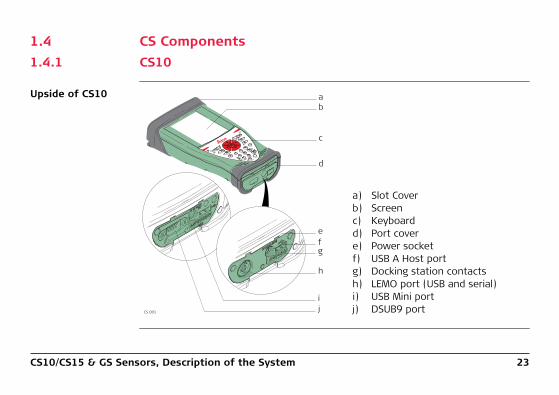
1.4 CS Components1.4.1 CS10
Upside of CS10
a) Slot Coverb) Screenc) Keyboardd) Port covere) Power socketf) USB A Host portg) Docking station contactsh) LEMO port (USB and serial)i) USB Mini portj) DSUB9 portCS_001
ba
c
d
fe
g
h
ij

24CS10/CS15 & GS Sensors, Description of the System
Underside of CS10
a) Hand strap bottom clipsb) Hand strapc) Battery compartmentd) Digital camerae) Hand strap top clipsf) Slotsg) Slot coverh) Stylusi) GS05 contactsj) CompactFlash card slotk) SIM card slotl) SD card slot
ab
efg
h
ijkl
cd
CS_008
SD
CF
CS10/CS15 & GS Sensors, Description of the System 25
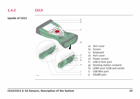
1.4.2 CS15
Upside of CS15
a) Slot coverb) Screenc) Keyboardd) Port covere) Power socketf) USB A Host portg) Docking station contactsh) LEMO port (USB and serial)i) USB Mini portj) DSUB9 portCS_002
fe
g
h
ij
ba
c
d
26CS10/CS15 & GS Sensors, Description of the System
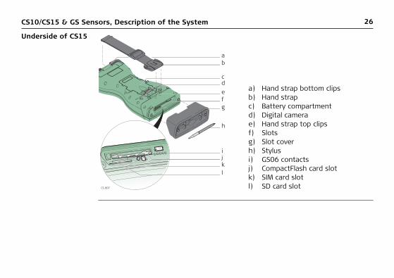
Underside of CS15
a) Hand strap bottom clipsb) Hand strapc) Battery compartmentd) Digital camerae) Hand strap top clipsf) Slotsg) Slot coverh) Stylusi) GS06 contactsj) CompactFlash card slotk) SIM card slotl) SD card slot
ab
efg
h
ijkl
cd
CS_007
SD
CF
CS10/CS15 & GS Sensors, Description of the System 27
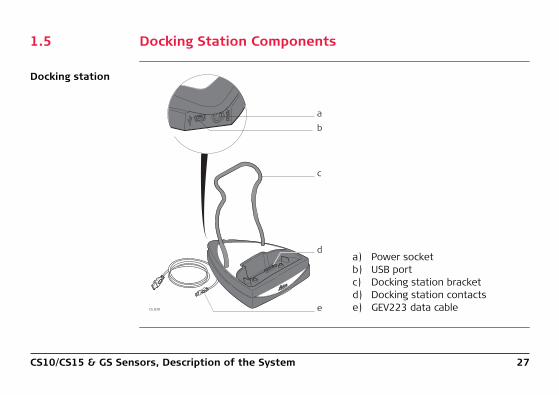
1.5 Docking Station Components
Docking station
a) Power socketb) USB portc) Docking station bracketd) Docking station contactse) GEV223 data cableCS_020
a
c
e
b
d

28CS10/CS15 & GS Sensors, Description of the System
1.6 GS08plus/GS12 Components
GS08plus/GS12 components
a) ON/OFF buttonb) LEDsc) LEMO port including USB portd) Mechanical Reference Plane (MRP)e) Clip-on contacts (only GS12)f) Battery compartment
TR
K BT P
WR
ONOFF
004097_001
ab
cdef
CS10/CS15 & GS Sensors, User Interface 29
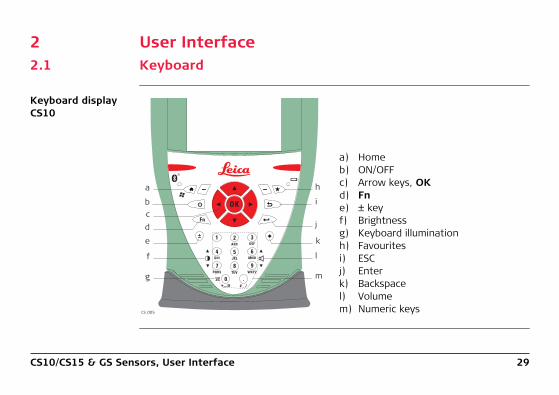
2 User Interface2.1 Keyboard
Keyboard display CS10
a) Homeb) ON/OFFc) Arrow keys, OKd) Fne) ± keyf) Brightnessg) Keyboard illuminationh) Favouritesi) ESCj) Enterk) Backspacel) Volumem) Numeric keys
2 31
.
5 64
8 97
0
Fn
ABC DEF
GHI JKL MNO
PQRS TUV WXYZ
OK
CS_005
e
f
g
d
a
bc
h
i
j
k
l
m
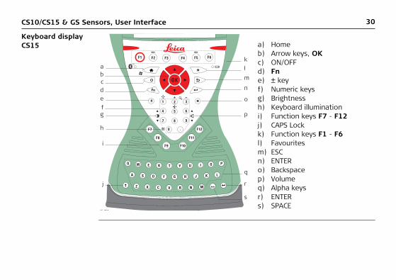
30CS10/CS15 & GS Sensors, User Interface
Keyboard display CS15 a) Home
b) Arrow keys, OKc) ON/OFFd) Fne) ± keyf) Numeric keysg) Brightnessh) Keyboard illuminationi) Function keys F7 - F12j) CAPS Lockk) Function keys F1 - F6l) Favouritesm) ESCn) ENTERo) Backspacep) Volumeq) Alpha keysr) ENTERs) SPACE
F1 F2
F7
F8
F9 F10
F11
F12
F3 F4 F5 F6
.
2 31
54
Fn
6
8 97
0
Q W E R T Y U I O P
L K J H G F D S A
Z X C V B N M
OK
k
e
g
h
c
ab
d
f
i
j
lm
n
o
p
q
r
s
CS 006
CS10/CS15 & GS Sensors, User Interface 31
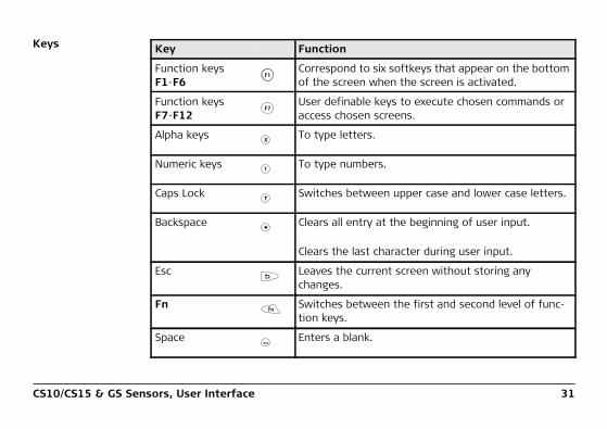
Keys Key Function
Function keysF1-F6
Correspond to six softkeys that appear on the bottom of the screen when the screen is activated.
Function keysF7-F12
User definable keys to execute chosen commands or access chosen screens.
Alpha keys To type letters.
Numeric keys To type numbers.
Caps Lock Switches between upper case and lower case letters.
Backspace Clears all entry at the beginning of user input.
Clears the last character during user input.
Esc Leaves the current screen without storing any changes.
Fn Switches between the first and second level of func-tion keys.
Space Enters a blank.
F1
F7
X
1
Fn

32CS10/CS15 & GS Sensors, User Interface
Enter Selects the highlighted line and leads to the next logical menu/ dialog.
Starts the edit mode for editable fields.
Opens a selectable list.
ON/OFF If CS10/CS15 already off: Turns on CS10/CS15 when held for 2 s.
If CS10/CS15 in stand-by mode: Turns on CS10/CS15 when held < 2 s.
If CS10/CS15 already on:• Puts CS10/CS15 into stand-by mode when held
< 2 s. Refer to "Stand-by".• Turns to Power Options menu when held for 2 s.
Refer to "Power Options menu".• Turns off CS10/CS15 when held for 5 s.
Favourites Goes to a website by simply clicking its name.
Home Switches to the Windows CE Start Menu.
Key Function

CS10/CS15 & GS Sensors, User Interface 33
Arrow keys Move the focus on the screen.
OK Selects the highlighted line and leads to the next logical menu/ dialog.
Starts the edit mode for editable fields.
Opens a selectable list.
Key Function
OK
OK
34CS10/CS15 & GS Sensors, User Interface
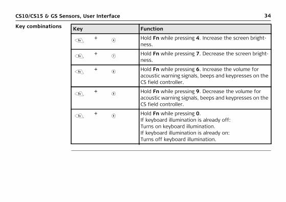
Key combinations Key Function
+ Hold Fn while pressing 4. Increase the screen bright-ness.
+ Hold Fn while pressing 7. Decrease the screen bright-ness.
+ Hold Fn while pressing 6. Increase the volume for acoustic warning signals, beeps and keypresses on the CS field controller.
+ Hold Fn while pressing 9. Decrease the volume for acoustic warning signals, beeps and keypresses on the CS field controller.
+ Hold Fn while pressing 0.If keyboard illumination is already off:Turns on keyboard illumination.If keyboard illumination is already on:Turns off keyboard illumination.
Fn 4
Fn 7
Fn 6
Fn 9
Fn 0
CS10/CS15 & GS Sensors, User Interface 35
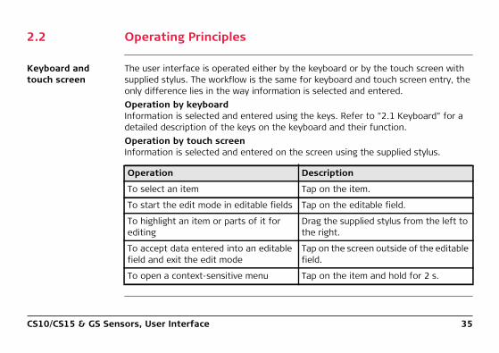
2.2 Operating Principles
Keyboard and touch screen
The user interface is operated either by the keyboard or by the touch screen with supplied stylus. The workflow is the same for keyboard and touch screen entry, the only difference lies in the way information is selected and entered.Operation by keyboardInformation is selected and entered using the keys. Refer to "2.1 Keyboard" for a detailed description of the keys on the keyboard and their function.Operation by touch screenInformation is selected and entered on the screen using the supplied stylus.
Operation Description
To select an item Tap on the item.
To start the edit mode in editable fields Tap on the editable field.
To highlight an item or parts of it for editing
Drag the supplied stylus from the left to the right.
To accept data entered into an editable field and exit the edit mode
Tap on the screen outside of the editable field.
To open a context-sensitive menu Tap on the item and hold for 2 s.
36CS10/CS15 & GS Sensors, Operation
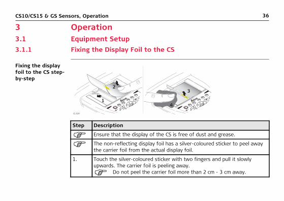
3 Operation3.1 Equipment Setup3.1.1 Fixing the Display Foil to the CS
Fixing the display foil to the CS step-by-step
Step Description
Ensure that the display of the CS is free of dust and grease.
The non-reflecting display foil has a silver-coloured sticker to peel away the carrier foil from the actual display foil.
1. Touch the silver-coloured sticker with two fingers and pull it slowly upwards. The carrier foil is peeling away.
Do not peel the carrier foil more than 2 cm - 3 cm away.
CS_029
1
23
4

CS10/CS15 & GS Sensors, Operation 37
2. Fix the laid open adhesive underside of the display foil at the display border.
Pay attention that the display foil is not fixed between display and display frame.
3. Peel away the carrier foil bit by bit and smooth it out slowly onto the display.
4. Potential air bubbles between display and display foil have to be smoothed out using the included microfibre cloth.
Do not use sharp objects!
Step Description

38CS10/CS15 & GS Sensors, Operation
3.1.2 Fixing a Hand Strap to the CS
Fixing the CS to a hand strap step-by-step
Step Description
Turn the CS field controller over.
1. Take the end of the hand strap and clip it to the base of CS field controller.
2. Compress the clips of the main hook.
3. Lower the main hook onto the pivot knob of the CS field controller. A click can be felt when the clip is secure.
CS_009
1
2
4
3
CS10/CS15 & GS Sensors, Operation 39
4. Adjust the length of the hand strap.
Step Description
40CS10/CS15 & GS Sensors, Operation
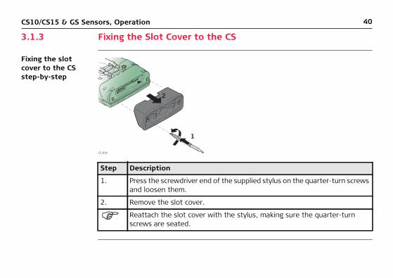
3.1.3 Fixing the Slot Cover to the CS
Fixing the slot cover to the CS step-by-step
Step Description
1. Press the screwdriver end of the supplied stylus on the quarter-turn screws and loosen them.
2. Remove the slot cover.
Reattach the slot cover with the stylus, making sure the quarter-turn screws are seated.
2
1
CS_016

CS10/CS15 & GS Sensors, Operation 41
3.1.4 Inserting and Removing a SIM Card
Insert and remove a SIM card step-by-step
Description
The SIM card is inserted into a slot inside the top of the CS10/CS15.
1. Loosen the screws inside the slot cover on top of the CS10/CS15 using the screwdriver end of the stylus.
2. Detach the slot cover from the CS10/CS15.
3. Slide the card firmly into the slot until it clicks into position.
SD
CF
24
3
1
CS_019
42CS10/CS15 & GS Sensors, Operation
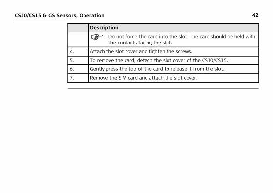
Do not force the card into the slot. The card should be held with the contacts facing the slot.
4. Attach the slot cover and tighten the screws.
5. To remove the card, detach the slot cover of the CS10/CS15.
6. Gently press the top of the card to release it from the slot.
7. Remove the SIM card and attach the slot cover.
Description

CS10/CS15 & GS Sensors, Operation 43
3.1.5 Setting up the Docking Station
Mounting compo-nents of the docking station step-by-step
Step Description
1. Hold the docking station bracket as shown in the illustration in relation to the docking station rack.
2. Slightly press the holder into the docking station rack. A click can be felt when the holder is secure.
CS_027
11
2
2

44CS10/CS15 & GS Sensors, Operation
3.1.6 Setting up as Handheld GNSS
The setup GS05/CS10 is identical to the setup GS06/CS15. For simplicity, the setup GS05/CS10 is used in the following.
Attaching the GS05 to the CS10 step-by-step
Step Description
Detach the slot cover from the CS10. Refer to "3.1.3 Fixing the Slot Cover to the CS".
1. Check the position of the contacts in the inner surface of the GS05.
1
2
34
CS_011

CS10/CS15 & GS Sensors, Operation 45
2. Attach the GS05 to the CS10.
3. Press the screwdriver end of the supplied stylus on the quarter-turn screws and tighten them.
4. To achieve the optimal satellite tracking performance, mount the AS05 (external GNSS antenna) on the GS05.
Step Description
46CS10/CS15 & GS Sensors, Operation
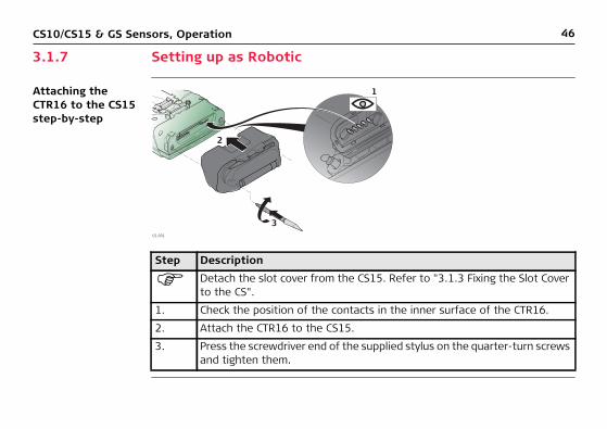
3.1.7 Setting up as Robotic
Attaching the CTR16 to the CS15 step-by-step
Step Description
Detach the slot cover from the CS15. Refer to "3.1.3 Fixing the Slot Cover to the CS".
1. Check the position of the contacts in the inner surface of the CTR16.
2. Attach the CTR16 to the CS15.
3. Press the screwdriver end of the supplied stylus on the quarter-turn screws and tighten them.
CS_031
1
2
3

CS10/CS15 & GS Sensors, Operation 47
3.1.8 Connecting to a Personal Computer
Microsoft ActiveSync (for PCs with Windows XP operating system) or Windows Mobile Device Center (for PCs with Windows Vista or Windows 7 operating system) is the synchronisation software for Windows mobile-based pocket PCs. Microsoft ActiveSync or Windows Mobile Device Center enables a PC and a Windows mobile-based pocket PC to communicate.
Install Leica Viva USB drivers
Step Description
1. Start the PC.
2. Insert the Leica Viva Series DVD.
3. Run the SetupViva&GR_USB_XX.exe to install the drivers necessary for Leica Viva devices. Depending on the version (32bit or 64bit) of the oper-ating system on your PC, you have to select between the three setup files following:• SetupViva&GR_USB_32bit.exe• SetupViva&GR_USB_64bit.exe• SetupViva&GR_USB_64bit_itanium.exe
The setup has to be run only once for all Leica Viva devices.

48CS10/CS15 & GS Sensors, Operation
4. The Welcome to InstallShield Wizard for Leica Viva & GR USB drivers window appears.
Ensure that all Leica Viva devices are disconnected from your PC before you continue!
5. Next>.
6. The Ready to Install the Program window appears.
7. Install. The drivers will be installed on your PC.
For PCs with Windows Vista or Windows 7 operating system: If not already installed, Windows Mobile Device Center will be installed additionally.
8. The InstallShield Wizard Completed window appears.
9. Check I have read the instructions and click Finish to exit the wizard.
Step Description
CS10/CS15 & GS Sensors, Operation 49
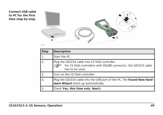
Connect USB cable to PC for the first time step-by-step
Step Description
1. Start the PC.
2. Plug the GEV234 cable into CS field controller.
For CS field controllers with DSUB9 connector, the GEV223 cable has to be used.
3. Turn on the CS field controller.
4. Plug the GEV234 cable into the USB port of the PC. The Found New Hard-ware Wizard starts up automatically.
5. Check Yes, this time only. Next>.
CS_026
2
3
4

50CS10/CS15 & GS Sensors, Operation
6. Check Install the software automatically (Recommended). Next>. The software for Remote NDIS based LGS CS Device will be installed on your PC.
7. Finish.
8. The Found New Hardware Wizard starts up automatically a second time.
9. Check Yes, this time only. Next>.
10. Check Install the software automatically (Recommended). Next>. The software for LGS CS USB Device will be installed on your PC.
11. Finish.
For PCs with Windows XP operating system:
12. Run the ActiveSync installation program if not already installed.
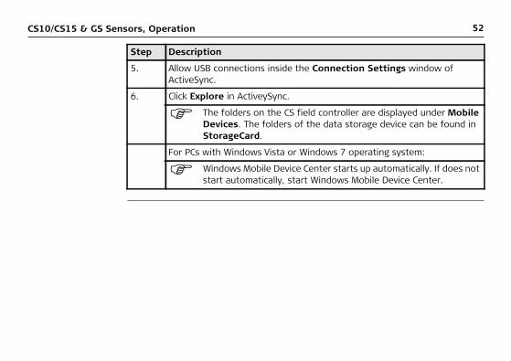
13. Allow USB connections inside the Connection Settings window of ActiveSync.
For PCs with Windows Vista or Windows 7 operating system:
14. Windows Mobile Device Center starts up automatically. If does not start automatically, start Windows Mobile Device Center.
Step Description

CS10/CS15 & GS Sensors, Operation 51
Connect to PC via USB cable step-by-step
Step Description
1. Start the PC.
2. Plug the GEV234 cable into CS field controller.
For CS field controllers with DSUB9 connector, the GEV223 cable has to be used.
3. Turn the CS field controller on.
4. Plug the GEV234 cable into the USB port of the PC.
For PCs with Windows XP operating system:
ActiveSync starts up automatically. If does not start automatically, start ActiveSync. If not already installed, run the ActiveSync instal-lation program.
CS_026
2
3
4
52CS10/CS15 & GS Sensors, Operation
5. Allow USB connections inside the Connection Settings window of ActiveSync.
6. Click Explore in ActiveySync.
The folders on the CS field controller are displayed under Mobile Devices. The folders of the data storage device can be found in StorageCard.
For PCs with Windows Vista or Windows 7 operating system:
Windows Mobile Device Center starts up automatically. If does not start automatically, start Windows Mobile Device Center.
Step Description

CS10/CS15 & GS Sensors, Operation 53
3.2 Power Functions
Turning CS field controller on
Press and hold power key ( ) for 2 s.
CS field controller must have a power supply.
Turning CS field controller off
Press and hold power key ( ) for 5 s.
CS field controller must be on.
Putting CS field controller into stand-by
Press and hold power key ( ) < 2 s.
CS field controller must be on.
54CS10/CS15 & GS Sensors, Operation
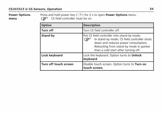
Power Options menu
Press and hold power key ( ) for 2 s to open Power Options menu.
CS field controller must be on.
Option Description
Turn off Turn CS field controller off.
Stand-by Put CS field controller into stand-by mode.
In stand-by mode, CS field controller shuts down and reduces power consumption. Rebooting from stand-by mode is quicker than a cold start after turning off.
Lock keyboard Lock the keyboard. Option turns to Unlock keyboard.
Turn off touch screen Disable touch screen. Option turns to Turn on touch screen.

CS10/CS15 & GS Sensors, Operation 55
Turn on GS08plus/GS12
To turn on the instrument press and hold the ON/OFF button for 2 s.
Turn off GS08plus/GS12
To turn off the instrument press and hold the ON/OFF button for 2 s.
Reset... Perform one of the following options:• Restart (restarts Windows CE)• Reset Windows CE (resets Windows CE and
communication settings to factory defaults)• Reset installed software (resets settings of
all installed software)• Reset Windows CE and installed software
(resets Windows CE and settings of all installed software)
Option Description
56CS10/CS15 & GS Sensors, Operation
3.3 Batteries3.3.1 Operating Principles
Charging / first-time use
• The battery must be charged prior to using it for the first time because it is deliv-ered with an energy content as low as possible.
• The permissible temperature range for charging is between 0°C to +40°C/ +32°F to +104°F. For optimal charging, we recommend charging the batteries at a low ambient temperature of +10°C to +20°C/+50°F to +68°F if possible.
• It is normal for the battery to become warm during charging. Using the chargers recommended by Leica Geosystems, it is not possible to charge the battery if the temperature is too high.
• For new batteries or batteries that have been stored for a long time (> three months), it is effectual to make only one charge/discharge cycle.
• For Li-Ion batteries, a single discharging and charging cycle is sufficient. We recommend carrying out the process when the battery capacity indicated on the charger or on a Leica Geosystems product deviates significantly from the actual battery capacity available.
Operation / Discharging
• The batteries can be operated from -20°C to +55°C/-4°F to +131°F.• Low operating temperatures reduce the capacity that can be drawn; high oper-
ating temperatures reduce the service life of the battery.
CS10/CS15 & GS Sensors, Operation 57
3.3.2 Changing the Battery
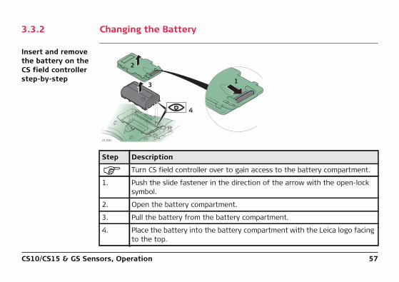
Insert and remove the battery on the CS field controller step-by-step
Step Description
Turn CS field controller over to gain access to the battery compartment.
1. Push the slide fastener in the direction of the arrow with the open-lock symbol.
2. Open the battery compartment.
3. Pull the battery from the battery compartment.
4. Place the battery into the battery compartment with the Leica logo facing to the top.
1
2
3
4
CS_010

58CS10/CS15 & GS Sensors, Operation
5. Close the battery compartment by pushing the slide fastener in the direc-tion of the arrow with the close-lock symbol.
Step Description
CS10/CS15 & GS Sensors, Operation 59
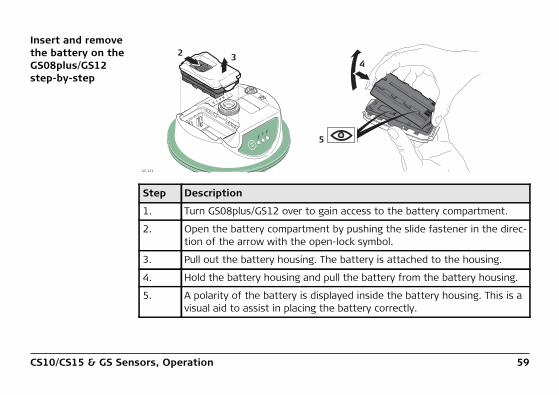
Insert and remove the battery on the GS08plus/GS12 step-by-step
Step Description
1. Turn GS08plus/GS12 over to gain access to the battery compartment.
2. Open the battery compartment by pushing the slide fastener in the direc-tion of the arrow with the open-lock symbol.
3. Pull out the battery housing. The battery is attached to the housing.
4. Hold the battery housing and pull the battery from the battery housing.
5. A polarity of the battery is displayed inside the battery housing. This is a visual aid to assist in placing the battery correctly.
2 3
GS_121
4
5
TR
KBTP
WR
ONOFF
60CS10/CS15 & GS Sensors, Operation
6. Place the battery onto the battery housing, ensuring that the contacts are facing outward. Click the battery into position.
7. Close the battery compartment by pushing the slide fastener in the direc-tion of the arrow with the close-lock symbol.
Step Description
CS10/CS15 & GS Sensors, Operation 61
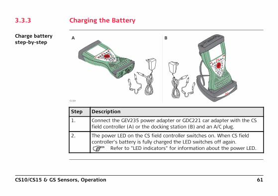
3.3.3 Charging the Battery
Charge battery step-by-step
Step Description
1. Connect the GEV235 power adapter or GDC221 car adapter with the CS field controller (A) or the docking station (B) and an A/C plug.
2. The power LED on the CS field controller switches on. When CS field controller’s battery is fully charged the LED switches off again.
Refer to "LED indicators" for information about the power LED.
A B
CS_024

62CS10/CS15 & GS Sensors, Operation
Charge battery for GS08plus/GS12
To charge the batteries for GS08plus/GS12, use the Leica Geosystems chargers GKL211 or GKL221. Refer to the GKL211 or GKL221 User Manual for further informa-tion.
CS10/CS15 & GS Sensors, Operation 63
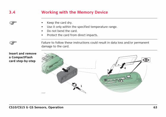
3.4 Working with the Memory Device
• Keep the card dry.• Use it only within the specified temperature range.• Do not bend the card.• Protect the card from direct impacts.
Failure to follow these instructions could result in data loss and/or permanent damage to the card.
Insert and remove a CompactFlash card step-by-step
CS_017
1
2 34
SD
CF

64CS10/CS15 & GS Sensors, Operation
Step Description
The CompactFlash card is inserted into a slot inside the top of the CS10/CS15.
1. Refer to "Fixing the slot cover to the CS step-by-step". Loosen the screws inside the slot cover on top of the CS10/CS15 using the screwdriver end of the stylus.
2. Detach the slot cover from the CS10/CS15.
3. Slide the card firmly into the slot until it clicks into position.
Do not force the card into the slot.
4. The card must be held with the contacts facing the slot.
5. Attach the slot cover and tighten the screws.
6. To remove the card, detach the slot cover of the CS10/CS15.
7. Press the eject button next to the card slot twice.
8. Remove the CompactFlash card and attach the slot cover.

CS10/CS15 & GS Sensors, Operation 65
Insert and remove an SD card step-by-step
Step Description
The SD card is inserted into a slot inside the top of the CS10/CS15.
1. Refer to "Fixing the slot cover to the CS step-by-step". Loosen the screws inside the slot cover on top of the CS10/CS15 using the screwdriver end of the stylus.
2. Detach the slot cover from the CS10/CS15.
3. Slide the card firmly into the slot until it clicks into position.
Do not force the card into the slot.
4. The card must be held with the contacts facing the slot.
CS_018
1
24
SD
CF
3
66CS10/CS15 & GS Sensors, Operation
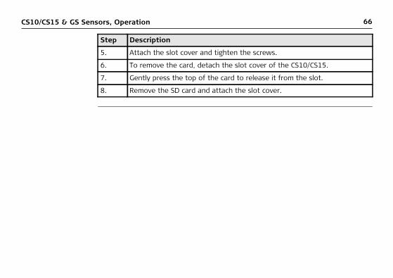
5. Attach the slot cover and tighten the screws.
6. To remove the card, detach the slot cover of the CS10/CS15.
7. Gently press the top of the card to release it from the slot.
8. Remove the SD card and attach the slot cover.
Step Description

CS10/CS15 & GS Sensors, Operation 67
3.5 LED Indicators on CS10/CS15
LED indicators DescriptionThe CS field controller has Light Emitting Diode indicators. They indicate the basic field controller status.
Diagram
a) Bluetooth LEDb) Power LED
Fn
OK
CS_023
ab
68CS10/CS15 & GS Sensors, Operation
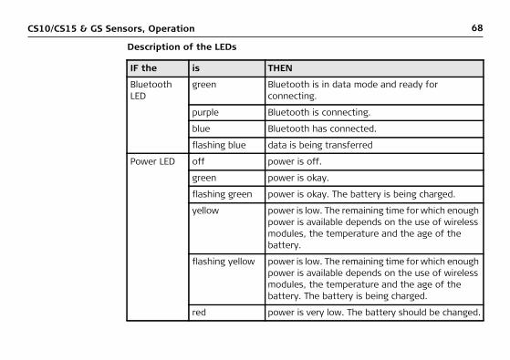
Description of the LEDs
IF the is THEN
Bluetooth LED
green Bluetooth is in data mode and ready for connecting.
purple Bluetooth is connecting.
blue Bluetooth has connected.
flashing blue data is being transferred
Power LED off power is off.
green power is okay.
flashing green power is okay. The battery is being charged.
yellow power is low. The remaining time for which enough power is available depends on the use of wireless modules, the temperature and the age of the battery.
flashing yellow power is low. The remaining time for which enough power is available depends on the use of wireless modules, the temperature and the age of the battery. The battery is being charged.
red power is very low. The battery should be changed.
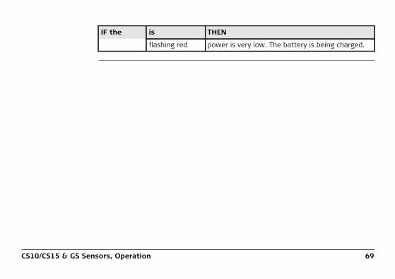
CS10/CS15 & GS Sensors, Operation 69
flashing red power is very low. The battery is being charged.
IF the is THEN

70CS10/CS15 & GS Sensors, Operation
3.6 LED Indicators on CTR16
LED indicators DescriptionThe CTR16 has a Light Emitting Diode indicator. It indicates the basic radio status.
Diagram
a) TPS radio LEDCS_033
a
CS10/CS15 & GS Sensors, Operation 71
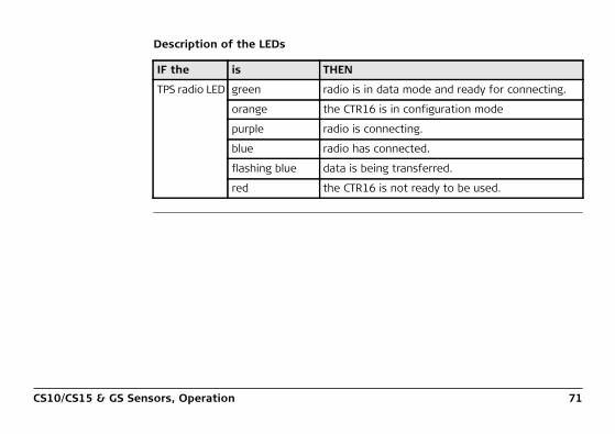
Description of the LEDs
IF the is THEN
TPS radio LED green radio is in data mode and ready for connecting.
orange the CTR16 is in configuration mode
purple radio is connecting.
blue radio has connected.
flashing blue data is being transferred.
red the CTR16 is not ready to be used.

72CS10/CS15 & GS Sensors, Operation
3.7 LED Indicators on GS08plus/GS12
LED indicators DescriptionThe GS08plus/GS12 instrument has Light Emitting Diode indicators. They indicate the basic instrument status.
Diagram
a) Tracking LED (TRK)b) Bluetooth LED (BT)c) Power LED (PWR)
TRKBT
PWR
ONOFF
003983_001
a b c a b c

CS10/CS15 & GS Sensors, Operation 73
Description of the LEDs
IF the is THEN
TRK LED off No satellites are tracked.
flashing green Less than four satellites are tracked, a position is not yet available.
green Enough satellites are tracked to compute a position.
red GS08plus/GS12 instrument is initialising.
BT LED green Bluetooth is in data mode and ready for connecting.
purple Bluetooth is connecting.
blue Bluetooth has connected.
flashing blue Data is being transferred.
GS12 PWR LED
off Power is off.
green Power is okay.
flashing green Power is low. The remaining time for which enough power is available depends on the type of survey, the temperature and the age of the battery.

74CS10/CS15 & GS Sensors, Operation
GS08plus PWR LED
off Power is off.
green Power is 100% - 20%.
red Power is 20% - 5%.
flashing red Power is low (<5%).The remaining time for which enough power is avail-able depends on the type of survey, the temperature and the age of the battery.
IF the is THEN

CS10/CS15 & GS Sensors, Operation 75
3.8 Using the Digital Camera
Overview Both CS field controllers are equipped with a digital camera located at the underside (refer to "1.4 CS Components"). If a hand strap or pole holder plate is mounted, the camera view is not limited. The camera application can be started from the desktop icon Camera or from the Start menu Start - Programs - Camera.
Taking a picture step-by-step
Step Description
1. Aim the camera to the desired target.
2. Check the view at the display.
3. Press OK or click Capture to take the picture.
Capture changes to Save.
4. Press OK again or click Save to open the Save As dialog.
5. Click Discard to reject the picture.
76CS10/CS15 & GS Sensors, Operation
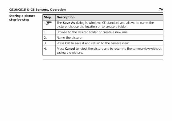
Storing a picture step-by-step
Step Description
The Save As dialog is Windows CE standard and allows to name the picture, choose the location or to create a folder.
1. Browse to the desired folder or create a new one.
2. Name the picture.
3. Press OK to save it and return to the camera view.
4. Press Cancel to reject the picture and to return to the camera view without saving the picture.

CS10/CS15 & GS Sensors, Care and Transport 77
4 Care and Transport4.1 Transport
Transport in a road vehicle
Never carry the product loose in a road vehicle, as it can be affected by shock and vibration. Always carry the product in its transport container and secure it.
Shipping When transporting the product by rail, air or sea, always use the complete original Leica Geosystems packaging, transport container and cardboard box, or its equiva-lent, to protect against shock and vibration.
Shipping, transport of batteries
When transporting or shipping batteries, the person in charge of the product must ensure that the applicable national and international rules and regulations are observed. Before transportation or shipping, contact your local passenger or freight transport company.

78CS10/CS15 & GS Sensors, Care and Transport
4.2 Storage
Product Respect the temperature limits when storing the equipment, particularly in summer if the equipment is inside a vehicle. Refer to "6 Technical Data" for information about temperature limits.
Li-Ion batteries • Refer to "6 Technical Data" for information about storage temperature range.• Remove batteries from the product and the charger before storing.• After storage recharge batteries before using.• Protect batteries from damp and wetness. Wet or damp batteries must be dried
before storing or use.• A storage temperature range of -20°C to +30°C/-4°F to 86°F in a dry environ-
ment is recommended to minimise self-discharging of the battery.• At the recommended storage temperature range, batteries containing a 50% to
100% charge can be stored for up to one year. After this storage period the batteries must be recharged.

CS10/CS15 & GS Sensors, Care and Transport 79
4.3 Cleaning and Drying
Product and acces-sories
• Use only a clean, soft, lint-free cloth for cleaning. If necessary, moisten the cloth with water or pure alcohol. Do not use other liquids; these may attack the polymer components.
Damp products Dry the product, the transport container, the foam inserts and the accessories at a temperature not greater than 40°C/104°F and clean them. Remove the battery cover and dry the battery compartment. Do not repack until everything is dry. Always close the transport container when using in the field.

80CS10/CS15 & GS Sensors, Care and Transport
Cables and plugs Keep plugs clean and dry. Blow away any dirt lodged in the plugs of the connecting cables.
Connectors with dust caps
Wet connectors must be dry before attaching the dust cap.

CS10/CS15 & GS Sensors, Safety Directions 81
5 Safety Directions5.1 General Introduction
Description The following directions enable the person responsible for the product, and the person who actually uses the equipment, to anticipate and avoid operational hazards.
The person responsible for the product must ensure that all users understand these directions and adhere to them.

82CS10/CS15 & GS Sensors, Safety Directions
5.2 Definition of Use
Intended use • Remote control of product.• Data communication with external appliances.• Recording measurements.• Computing with software.• Carrying out measurement tasks using various GNSS measuring techniques.• Recording GNSS and point related data.• Measuring raw data and computing coordinates using carrier phase and code
signal from GNSS satellites.

CS10/CS15 & GS Sensors, Safety Directions 83
Reasonably fore-seeable misuse
• Use of the product without instruction.• Use outside of the intended use and limits.• Disabling safety systems.• Removal of hazard notices.• Opening the product using tools, for example screwdriver, unless this is
permitted for certain functions.• Modification or conversion of the product.• Use after misappropriation.• Use of products with recognisable damages or defects.• Use with accessories from other manufacturers without the prior explicit
approval of Leica Geosystems.• Inadequate safeguards at the working site.• Controlling of machines, moving objects or similar monitoring application without
additional control- and safety installations.

84CS10/CS15 & GS Sensors, Safety Directions
5.3 Limits of Use
Environment Suitable for use in an atmosphere appropriate for permanent human habitation: not suitable for use in aggressive or explosive environments.
� DANGER Local safety authorities and safety experts must be contacted before working in hazardous areas, or close to electrical installations or similar situations by the person in charge of the product.
The following advice is only valid for battery charger, power adapter and car adapter.
Environment Suitable for use in dry environments only and not under adverse conditions.

CS10/CS15 & GS Sensors, Safety Directions 85
5.4 Responsibilities
Manufacturer of the product
Leica Geosystems AG, CH-9435 Heerbrugg, hereinafter referred to as Leica Geosystems, is responsible for supplying the product, including the user manual and original accessories, in a safe condition.
Person respon-sible for the product
The person responsible for the product has the following duties:• To understand the safety instructions on the product and the instructions in the
user manual.• To ensure that it is used in accordance with the instructions.• To be familiar with local regulations relating to safety and accident prevention.• To inform Leica Geosystems immediately if the product and the application
becomes unsafe.• To ensure that the national laws, regulations and conditions for the operation of
e.g. radio transmitters, lasers are respected.

86CS10/CS15 & GS Sensors, Safety Directions
5.5 Hazards of Use
� DANGER Because of the risk of electrocution, it is dangerous to use poles and extensions in the vicinity of electrical installations such as power cables or electrical railways.Precautions:Keep at a safe distance from electrical installations. If it is essential to work in this environment, first contact the safety authorities responsible for the electrical instal-lations and follow their instructions.
� WARNING During dynamic applications, for example stakeout procedures there is a danger of accidents occurring if the user does not pay attention to the environmental condi-tions around, for example obstacles, excavations or traffic.Precautions:The person responsible for the product must make all users fully aware of the existing dangers.
CS10/CS15 & GS Sensors, Safety Directions 87
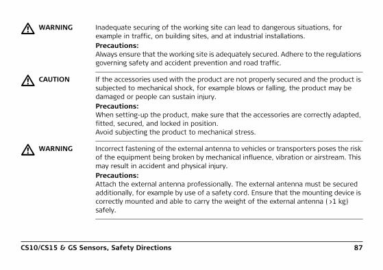
� WARNING Inadequate securing of the working site can lead to dangerous situations, for example in traffic, on building sites, and at industrial installations.Precautions:Always ensure that the working site is adequately secured. Adhere to the regulations governing safety and accident prevention and road traffic.
� CAUTION If the accessories used with the product are not properly secured and the product is subjected to mechanical shock, for example blows or falling, the product may be damaged or people can sustain injury.Precautions:When setting-up the product, make sure that the accessories are correctly adapted, fitted, secured, and locked in position.Avoid subjecting the product to mechanical stress.
� WARNING Incorrect fastening of the external antenna to vehicles or transporters poses the risk of the equipment being broken by mechanical influence, vibration or airstream. This may result in accident and physical injury.Precautions:Attach the external antenna professionally. The external antenna must be secured additionally, for example by use of a safety cord. Ensure that the mounting device is correctly mounted and able to carry the weight of the external antenna (>1 kg) safely.

88CS10/CS15 & GS Sensors, Safety Directions
� WARNING If the product is used with accessories, for example masts, staffs, poles, you may increase the risk of being struck by lightning.Precautions:Do not use the product in a thunderstorm.
� DANGER If the product is used with accessories, for example on masts, staffs, poles, you may increase the risk of being struck by lightning. Danger from high voltages also exists near power lines. Lightning, voltage peaks, or the touching of power lines can cause damage, injury and death.Precautions:• Do not use the product in a thunderstorm as you can increase the risk of being
struck by lightning.• Be sure to remain at a safe distance from electrical installations. Do not use the
product directly under or close to power lines. If it is essential to work in such an environment contact the safety authorities responsible for electrical installations and follow their instructions.
• If the product has to be permanently mounted in an exposed location, it is advis-able to provide a lightning conductor system. A suggestion on how to design a lightning conductor for the product is given below. Always follow the regulations in force in your country regarding grounding antennas and masts. These instal-lations must be carried out by an authorised specialist.
• To prevent damages due to indirect lightning strikes (voltage spikes) cables, for example for antenna, power source or modem should be protected with appro-

CS10/CS15 & GS Sensors, Safety Directions 89
priate protection elements, like a lightning arrester. These installations must be carried out by an authorised specialist.
• If there is a risk of a thunderstorm, or if the equipment is to remain unused and unattended for a long period, protect your product additionally by unplugging all systems components and disconnecting all connecting cables and supply cables, for example, instrument - antenna.
Lightning conduc-tors
Suggestion for design of a lightning conductor for a GNSS system:1) On non-metallic structures
Protection by air terminals is recommended. An air terminal is a pointed solid or tubular rod of conducting material with proper mounting and connection to a conductor. The position of four air terminals can be uniformly distributed around the antenna at a distance equal to the height of the air terminal.The air terminal diameter should be 12 mm for copper or 15 mm for aluminium. The height of the air terminals should be 25 cm to 50 cm. All air terminals should be connected to the down conductors. The diameter of the air terminal should be kept to a minimum to reduce GNSS signal shading.
2) On metallic structuresProtection is as described for non-metallic structures, but the air terminals can be connected directly to the conducting structure without the need for down conductors.
90CS10/CS15 & GS Sensors, Safety Directions
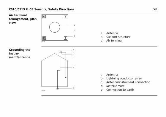
Air terminal arrangement, plan view
Grounding the instru-ment/antenna
a) Antennab) Support structurec) Air terminalGS_039
a
b
c
a) Antennab) Lightning conductor arrayc) Antenna/instrument connectiond) Metallic maste) Connection to earthGS_040
e
d
c
ab
CS10/CS15 & GS Sensors, Safety Directions 91
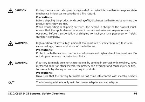
� CAUTION During the transport, shipping or disposal of batteries it is possible for inappropriate mechanical influences to constitute a fire hazard.Precautions:Before shipping the product or disposing of it, discharge the batteries by running the product until they are flat.When transporting or shipping batteries, the person in charge of the product must ensure that the applicable national and international rules and regulations are observed. Before transportation or shipping contact your local passenger or freight transport company.
� WARNING High mechanical stress, high ambient temperatures or immersion into fluids can cause leakage, fire or explosions of the batteries.Precautions:Protect the batteries from mechanical influences and high ambient temperatures. Do not drop or immerse batteries into fluids.
� WARNING If battery terminals are short circuited e.g. by coming in contact with jewellery, keys, metalized paper or other metals, the battery can overheat and cause injury or fire, for example by storing or transporting in pockets.Precautions:Make sure that the battery terminals do not come into contact with metallic objects.
The following advice is only valid for power adapter and car adapter.

92CS10/CS15 & GS Sensors, Safety Directions
� WARNING If you open the product, either of the following actions may cause you to receive an electric shock.• Touching live components• Using the product after incorrect attempts were made to carry out repairsPrecautions:Do not open the product. Only Leica Geosystems authorised service workshops are entitled to repair these products.
The following advice is only valid for power adapter or docking station.
� WARNING The product is not designed for use under wet and severe conditions. If unit becomes wet it may cause you to receive an electric shock.Precautions:Use the product only in dry environments, for example in buildings or vehicles. Protect the product against humidity. If the product becomes humid, it must not be used!
CS10/CS15 & GS Sensors, Safety Directions 93
� WARNING If the product is improperly disposed of, the following can happen:• If polymer parts are burnt, poisonous gases are produced which may impair
health.• If batteries are damaged or are heated strongly, they can explode and cause
poisoning, burning, corrosion or environmental contamination.• By disposing of the product irresponsibly you may enable unauthorised persons
to use it in contravention of the regulations, exposing themselves and third parties to the risk of severe injury and rendering the environment liable to contamination.
Precautions:
Product-specific treatment and waste management information can be downloaded from the Leica Geosystems home page at http://www.leica-geosystems.com/treatment or received from your Leica Geosystems dealer.
� WARNING Only Leica Geosystems authorised service workshops are entitled to repair these products.
The product must not be disposed with household waste.Dispose of the product appropriately in accordance with the national regulations in force in your country.Always prevent access to the product by unauthorised personnel.
94CS10/CS15 & GS Sensors, Safety Directions
5.6 Electromagnetic Compatibility EMC
Description The term Electromagnetic Compatibility is taken to mean the capability of the product to function smoothly in an environment where electromagnetic radiation and elec-trostatic discharges are present, and without causing electromagnetic disturbances to other equipment.
� WARNING Electromagnetic radiation can cause disturbances in other equipment.
Although the product meets the strict regulations and standards which are in force in this respect, Leica Geosystems cannot completely exclude the possibility that other equipment may be disturbed.
� CAUTION There is a risk that disturbances may be caused in other equipment if the product is used with accessories from other manufacturers, for example field computers, personal computers, two-way radios, non-standard cables or external batteries.Precautions:Use only the equipment and accessories recommended by Leica Geosystems. When combined with the product, they meet the strict requirements stipulated by the guidelines and standards. When using computers and two-way radios, pay attention to the information about electromagnetic compatibility provided by the manufac-turer.

CS10/CS15 & GS Sensors, Safety Directions 95
� CAUTION Disturbances caused by electromagnetic radiation can result in erroneous measure-ments.Although the product meets the strict regulations and standards which are in force in this respect, Leica Geosystems cannot completely exclude the possibility that the product may be disturbed by intense electromagnetic radiation, for example, near radio transmitters, two-way radios or diesel generators.Precautions:Check the plausibility of results obtained under these conditions.
� CAUTION If the product is operated with connecting cables attached at only one of their two ends, for example external supply cables, interface cables, the permitted level of electromagnetic radiation may be exceeded and the correct functioning of other products may be impaired. Precautions:While the product is in use, connecting cables, for example product to external battery, product to computer, must be connected at both ends.
96CS10/CS15 & GS Sensors, Safety Directions
Radios or digital cellular phones
Use of product with radio or digital cellular phone devices:
� WARNING Electromagnetic fields can cause disturbances in other equipment, in installations, in medical devices, for example pacemakers or hearing aids and in aircraft. It can also affect humans and animals.Precautions:Although the product meets the strict regulations and standards which are in force in this respect, Leica Geosystems cannot completely exclude the possibility that other equipment can be disturbed or that humans or animals can be affected.
• Do not operate the product with radio or digital cellular phone devices in the vicinity of filling stations or chemical installations, or in other areas where an explosion hazard exists.
• Do not operate the product with radio or digital cellular phone devices near to medical equipment.
• Do not operate the product with radio or digital cellular phone devices in aircraft.

CS10/CS15 & GS Sensors, Safety Directions 97
5.7 FCC Statement, Applicable in U.S.
The greyed paragraph below is only applicable for products without radio.
� WARNING This equipment has been tested and found to comply with the limits for a Class B digital device, pursuant to part 15 of the FCC rules.These limits are designed to provide reasonable protection against harmful interfer-ence in a residential installation.This equipment generates, uses and can radiate radio frequency energy and, if not installed and used in accordance with the instructions, may cause harmful interfer-ence to radio communications. However, there is no guarantee that interference will not occur in a particular installation.If this equipment does cause harmful interference to radio or television reception, which can be determined by turning the equipment off and on, the user is encour-aged to try to correct the interference by one or more of the following measures:• Reorient or relocate the receiving antenna.• Increase the separation between the equipment and the receiver.• Connect the equipment into an outlet on a circuit different from that to which
the receiver is connected.• Consult the dealer or an experienced radio/TV technician for help.
98CS10/CS15 & GS Sensors, Safety Directions
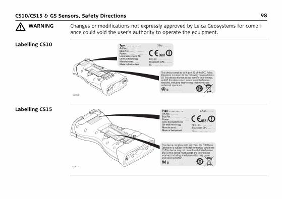
� WARNING Changes or modifications not expressly approved by Leica Geosystems for compli-ance could void the user's authority to operate the equipment.
Labelling CS10
Labelling CS15
CS_014
CS_015

CS10/CS15 & GS Sensors, Safety Directions 99
Labelling CTR16
Labelling GS05, GS06
CS_032
This device complies with part 15 of the FCC Rules. Operation is subject to the following two conditions: (1) This device may not cause harmful interference, and (2) this device must accept any interference received, including interference that may cause undesired operation.
Type: CTR16Equip.No.: . . . . . . .FCC-ID: RFD-CTR16IC: 3177A-CTR16
Leica Geosystems AGCH-9435 HeerbruggManufactured: . . . .Made in Switzerland
S.No.: . . . . . .Art.No.: . . . . . .
CS_012
100CS10/CS15 & GS Sensors, Safety Directions
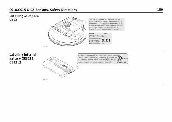
Labelling GS08plus, GS12
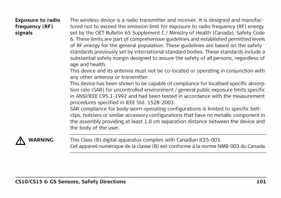
Labelling internal battery GEB211, GEB212
This device complies with part 15 of the FCC Rules. Operation is subject to the following two conditions: (1) This device may not cause harm-ful interference, and (2) this device must accept any interference received, including inter-ference that may cause undesired operation.
Type: GS....... Art.No.: ......Equip.No.: XXXXXX S.No.: ......Power: 12V---, nominal 1/0.5A max.Leica Geosystems AGCH-9435 HeerbruggManufactured: 2004Made in Switzerland S.No.: ......
GS_123
This device complies with part 15 of the FCC Rules. Operation is subject to the following two conditions: (1) This device may not cause harmful interference, and (2) this device must accept any interference received, including interference that may cause undesired operation.
.................................
.......................
......................................................
..........................................
....
..........
.................................................................................
GEB_001
CS10/CS15 & GS Sensors, Safety Directions 101
Exposure to radio frequency (RF) signals
The wireless device is a radio transmitter and receiver. It is designed and manufac-tured not to exceed the emission limit for exposure to radio frequency (RF) energy set by the OET Bulletin 65 Supplement C / Ministry of Health (Canada), Safety Code 6. These limits are part of comprehensive guidelines and established permitted levels of RF energy for the general population. These guidelines are based on the safety standards previously set by international standard bodies. These standards include a substantial safety margin designed to assure the safety of all persons, regardless of age and health.This device and its antenna must not be co-located or operating in conjunction with any other antenna or transmitter.This device has been shown to be capable of compliance for localised specific absorp-tion rate (SAR) for uncontrolled environment / general public exposure limits specific in ANSI/IEEE C95.1-1992 and had been tested in accordance with the measurement procedures specified in IEEE Std. 1528-2003.SAR compliance for body-worn operating configurations is limited to specific belt-clips, holsters or similar accessory configurations that have no metallic component in the assembly providing at least 1.0 cm separation distance between the device and the body of the user.
� WARNING This Class (B) digital apparatus complies with Canadian ICES-003.Cet appareil numérique de la classe (B) est conforme à la norme NMB-003 du Canada.

102CS10/CS15 & GS Sensors, Technical Data
6 Technical Data6.1 CS10/CS15 Technical Data
Design Glass reinforced polymer housing with optional integrated battery and radio modem.
Control unit CS10
Display: VGA (480 x 640 pixels),graphics capable LCD, illumination,touch screen, colour
Keyboard: 26 keys, illuminationTouch screen: Toughened film on glassSound: Integrated sealed speaker and microphoneDigital camera: Resolution: 1600 x 1200 pixels, fixed focus lens, image
capture: JPEG

CS10/CS15 & GS Sensors, Technical Data 103
CS15
Dimensions
Weight
Display: VGA (640 x 480 pixels),graphics capable LCD, illumination,touch screen, colour
Keyboard: 65 keys including 12 function keys, illuminationTouch screen: Toughened film on glassSound: Integrated sealed speaker and microphoneDigital camera: Resolution: 1600 x 1200 pixels, fixed focus lens, image
capture: JPEG
Type Length [m] Width [m] Thickness [m]
CS10 0.200 0.102 0.045
CS15 0.245 0.125 0.045
Type Weight [kg]/[lbs]
CS10, with battery, internal radio and WLAN 0.720/1.587
CS15, with battery, internal radio and WLAN 0.870/1.918
104CS10/CS15 & GS Sensors, Technical Data
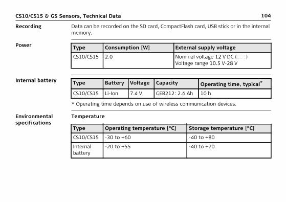
Recording Data can be recorded on the SD card, CompactFlash card, USB stick or in the internal memory.
Power
Internal battery
* Operating time depends on use of wireless communication devices.
Environmental specifications
Temperature
Type Consumption [W] External supply voltage
CS10/CS15 2.0 Nominal voltage 12 V DC ( )Voltage range 10.5 V-28 V
Type Battery Voltage Capacity Operating time, typical*
CS10/CS15 Li-Ion 7.4 V GEB212: 2.6 Ah 10 h
Type Operating temperature [°C] Storage temperature [°C]
CS10/CS15 -30 to +60 -40 to +80
Internal battery
-20 to +55 -40 to +70

CS10/CS15 & GS Sensors, Technical Data 105
Protection against water, dust and sand
Humidity
Interfaces
Type Protection
CS10/CS15 IP67 (IEC60529)Dust tightWaterproof to 1 m temporary immersion
Type Protection
CS10/CS15 Up to 100 %The effects of condensation are to be effectively counteracted by periodically drying out CS10/CS15.
Type RS232 USB Host USB OTG Bluetooth WLAN
CS10/CS15 LEMO port or DSUB9
LEMO port or USB A
LEMO port, USB Mini-AB or docking station contacts
Class 2 802.11b/g
106CS10/CS15 & GS Sensors, Technical Data
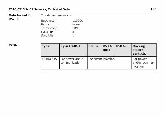
Data format for RS232
The default values are:
Ports
Baud rate: 115200 Parity: NoneTerminator: CR/LFData bits: 8Stop bits: 1
Type 8 pin LEMO-1 DSUB9 USB A Host
USB Mini Docking station contacts
CS10/CS15 For power and/or communication
For communication For power and/or commu-nication

CS10/CS15 & GS Sensors, Technical Data 107
6.2 GS05/GS06 Technical Data6.2.1 Tracking Characteristics
Instrument tech-nology
SmartTrack+
Satellite reception Single frequency
Instrument chan-nels
Depending on the satellite systems and signals configured, a maximum number of 14 channels is allocated.
Supported codes and phases
GPS
GS05/GS06: Up to 14 channels continuous tracking on L1 (GPS); up to 14 channels continuous tracking on L1 (GLONASS); one channel tracking SBAS.
Type L1
GS05/GS06 Carrier phase, C/A-code

108CS10/CS15 & GS Sensors, Technical Data
GLONASS
Carrier phase and code measurements on L1 (GPS) are fully independent with AS on or off.
Satellites tracked
Type L1
GS05/GS06 Carrier phase, C/A-code
GS05/GS06: Up to 14 simultaneously on L1 (GPS) + up to 14 simultaneously on L1 (GLONASS) + up to one SBAS

CS10/CS15 & GS Sensors, Technical Data 109
6.2.2 Accuracy
Accuracy is dependent upon various factors including the number of satellites tracked, constellation geometry, observation time, ephemeris accuracy, ionospheric disturbance, multipath and resolved ambiguities.
The following accuracies, given as root mean square, are based on measurements processed using LGO and on real-time measurements.
The use of multiple GNSS systems can increase accuracy by up to 30% relative to GPS only.
Differential code The baseline precision of a differential code solution for static and kinematic surveys is 40 cm. The measurement of accuracy is compliant with ISO 17123-8.
Differential phase in post-processing
Static Kinematic
Horizontal Vertical Horizontal Vertical
5 mm + 0.5 ppm 10 mm + 0.5 ppm 10 mm + 1 ppm 20 mm + 1 ppm

110CS10/CS15 & GS Sensors, Technical Data
6.2.3 Technical Data
Description and use
The table gives a description and the intended use of the GS05/GS06.
Dimensions
Connector 5 pin interface port
Type Description Use
GS05 L1 GPS, GLONASS SmartTrack+ antenna.
With CS10 field controller.
GS06 L1 GPS, GLONASS SmartTrack+ antenna.
With CS15 field controller.
Type Length [m] Width [m] Thickness [m]
GS05 with CS10
0.278 0.102 0.045
GS06 with CS15
0.323 0.125 0.045

CS10/CS15 & GS Sensors, Technical Data 111
Weight
Power
Electrical data
Type Weight [kg]/[lbs]
GS05 with CS10 0.750/1.653
GS06 with CS15 0.910/2.006
Power consumption: 0.5 W typically, 45 mAExternal supply voltage: Nominal 12 V DC ( ), voltage range 5 V-28 V DC
Type GS05/GS06
Voltage -
Current -
Frequency GPS L1 1575.42 MHz
GLONASS L1 1602.5625 MHz-1611.5 MHz
Gain Typically 27 dBi
Noise Figure Typically < 2 dBi

112CS10/CS15 & GS Sensors, Technical Data
Environmental specifications
Temperature
Protection against water, dust and sand
Humidity
Operating temperature [°C] Storage temperature [°C]
-30 to +60 -40 to +80
Protection
IP67 (IEC 60529)
Dust tight
Protected against water jets
Waterproof to 1 m temporary immersion
Protection
Up to 100 %
The effects of condensation are to be effectively counteracted by periodically drying out the antenna.

CS10/CS15 & GS Sensors, Technical Data 113
6.3 CTR16 Technical Data
Description and use
The CTR16 is a high performance wireless data transfer device operating in the 2.4 GHz frequency band. The CTR16 can be used on CS15 controller only for commu-nication to a total station with RH16 or TCPS29 attached.
Dimensions
Connector 5 pin interface port
Weight 0.155 kg / 0.342 lbs
Power
Type Length [m] Width [m] Thickness [m]
CTR16 0.131 0.069 0.053
Type CTR16
Power consumption 100 mA nominal (5 V), 200 mA max.
Power supply From instrument
114CS10/CS15 & GS Sensors, Technical Data
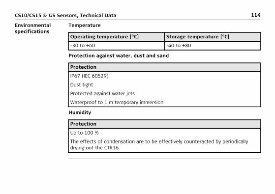
Environmental specifications
Temperature
Protection against water, dust and sand
Humidity
Operating temperature [°C] Storage temperature [°C]
-30 to +60 -40 to +80
Protection
IP67 (IEC 60529)
Dust tight
Protected against water jets
Waterproof to 1 m temporary immersion
Protection
Up to 100 %
The effects of condensation are to be effectively counteracted by periodically drying out the CTR16.

CS10/CS15 & GS Sensors, Technical Data 115
6.4 GS08plus/GS126.4.1 Tracking Characteristics
Instrument tech-nology
SmartTrack+
Satellite reception
Instrument chan-nels
Depending on the satellite systems and signals configured, a maximum number of 120 channels is allocated.
GS08plus: Dual frequency.GS12: Triple frequency.
GS08plus: Up to 16 channels continuous tracking on L1, L2 (GPS); up to 14 channels continuous tracking on L1 and L2 (GLONASS); four channels tracking SBAS (EGNOS, WAAS, MSAS, GAGAN).
GS12: Up to 16 channels continuous tracking on L1, L2 and L5 (GPS); up to 14 channels continuous tracking on L1 and L2 (GLONASS); up to 14 channels continuous tracking on E1, E5a, E5b and Alt-BOC (Galileo); four channels tracking SBAS (EGNOS, WAAS, MSAS, GAGAN).

116CS10/CS15 & GS Sensors, Technical Data
Supported codes and phases
GPS
GLONASS
Galileo
Carrier phase and code measurements on L1, L2 and L5 (GPS) are fully independent with AS on or off.
Type L1 L2 L5
GS08plus Carrier phase, C/A-code
Carrier phase, C code (L2C) and P2-code
-
GS12 Carrier phase, C/A-code
Carrier phase, C code (L2C) and P2-code
Carrier phase, code
Type L1 L2
GS08plus Carrier phase, C/A-code Carrier phase, P2-code
GS12 Carrier phase, C/A-code Carrier phase, P2-code
Type E1 E5a E5b Alt-BOC
GS12 Carrier phase, code
Carrier phase, code
Carrier phase, code
Carrier phase, code

CS10/CS15 & GS Sensors, Technical Data 117
Satellites tracked GS08plus: Up to 16 simultaneously on L1, L2 (GPS) + up to 14 simultane-ously on L1 and L2 (GLONASS)+ up to four SBAS (EGNOS, WAAS, MSAS, GAGAN)
GS12: Up to 16 simultaneously on L1, L2 and L5 (GPS) + up to 14 simultaneously on L1 and L2 (GLONASS) + up to 14 simultane-ously on E1, E5a, E5b and Alt-BOC (Galileo) + up to four SBAS (EGNOS, WAAS, MSAS, GAGAN)
118CS10/CS15 & GS Sensors, Technical Data
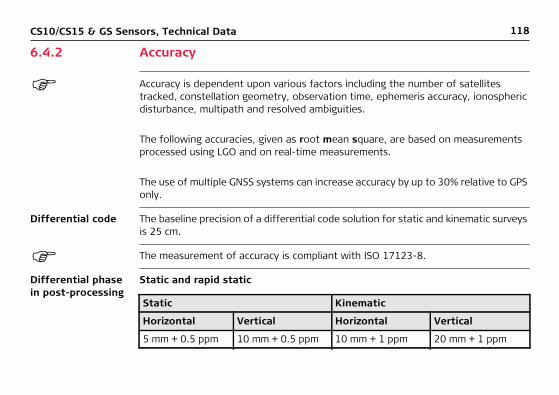
6.4.2 Accuracy
Accuracy is dependent upon various factors including the number of satellites tracked, constellation geometry, observation time, ephemeris accuracy, ionospheric disturbance, multipath and resolved ambiguities.
The following accuracies, given as root mean square, are based on measurements processed using LGO and on real-time measurements.
The use of multiple GNSS systems can increase accuracy by up to 30% relative to GPS only.
Differential code The baseline precision of a differential code solution for static and kinematic surveys is 25 cm.
The measurement of accuracy is compliant with ISO 17123-8.
Differential phase in post-processing
Static and rapid static
Static Kinematic
Horizontal Vertical Horizontal Vertical
5 mm + 0.5 ppm 10 mm + 0.5 ppm 10 mm + 1 ppm 20 mm + 1 ppm
CS10/CS15 & GS Sensors, Technical Data 119
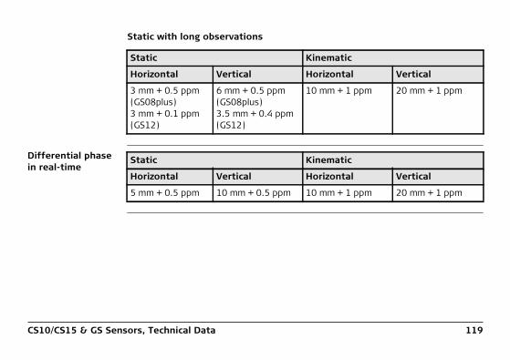
Static with long observations
Differential phase in real-time
Static Kinematic
Horizontal Vertical Horizontal Vertical
3 mm + 0.5 ppm (GS08plus)3 mm + 0.1 ppm (GS12)
6 mm + 0.5 ppm (GS08plus)3.5 mm + 0.4 ppm (GS12)
10 mm + 1 ppm 20 mm + 1 ppm
Static Kinematic
Horizontal Vertical Horizontal Vertical
5 mm + 0.5 ppm 10 mm + 0.5 ppm 10 mm + 1 ppm 20 mm + 1 ppm
120CS10/CS15 & GS Sensors, Technical Data
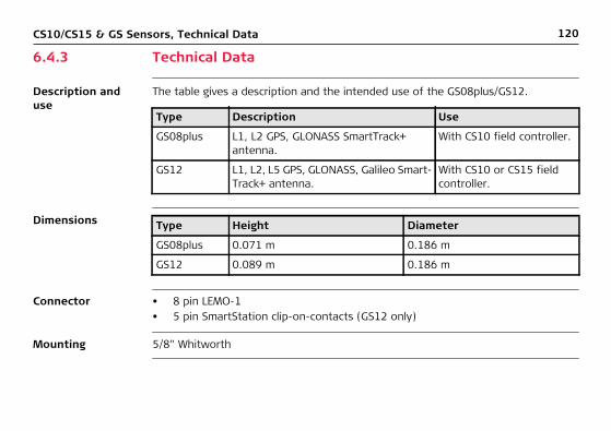
6.4.3 Technical Data
Description and use
The table gives a description and the intended use of the GS08plus/GS12.
Dimensions
Connector • 8 pin LEMO-1• 5 pin SmartStation clip-on-contacts (GS12 only)
Mounting 5/8" Whitworth
Type Description Use
GS08plus L1, L2 GPS, GLONASS SmartTrack+ antenna.
With CS10 field controller.
GS12 L1, L2, L5 GPS, GLONASS, Galileo Smart-Track+ antenna.
With CS10 or CS15 field controller.
Type Height Diameter
GS08plus 0.071 m 0.186 m
GS12 0.089 m 0.186 m
CS10/CS15 & GS Sensors, Technical Data 121
Weight
Power
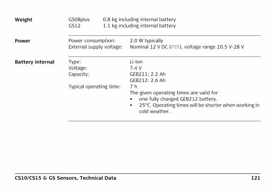
Battery internal
GS08plus 0.8 kg including internal batteryGS12 1.1 kg including internal battery
Power consumption: 2.0 W typicallyExternal supply voltage: Nominal 12 V DC ( ), voltage range 10.5 V-28 V
Type: Li-IonVoltage: 7.4 VCapacity: GEB211: 2.2 Ah
GEB212: 2.6 AhTypical operating time: 7 h
The given operating times are valid for• one fully charged GEB212 battery.• 25°C. Operating times will be shorter when working in
cold weather.
122CS10/CS15 & GS Sensors, Technical Data
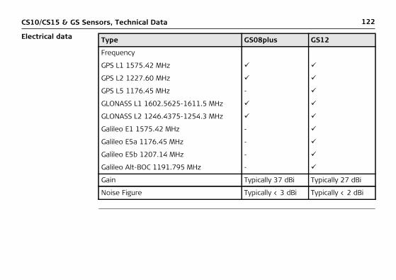
Electrical data Type GS08plus GS12
Frequency
GPS L1 1575.42 MHz
GPS L2 1227.60 MHz
GPS L5 1176.45 MHz -
GLONASS L1 1602.5625-1611.5 MHz
GLONASS L2 1246.4375-1254.3 MHz
Galileo E1 1575.42 MHz -
Galileo E5a 1176.45 MHz -
Galileo E5b 1207.14 MHz -
Galileo Alt-BOC 1191.795 MHz -
Gain Typically 37 dBi Typically 27 dBi
Noise Figure Typically < 3 dBi Typically < 2 dBi

CS10/CS15 & GS Sensors, Technical Data 123
Environmental specifications
Temperature
Protection against water, dust and sand
Humidity
Operating temperature [°C] Storage temperature [°C]
-40 to +65 -40 to +80
Bluetooth: -30 to +65
Protection
IP67 (IEC 60529)
Dusttight
Protected against water jets
Waterproof to 1 m temporary immersion
Protection
Up to 100 %
The effects of condensation are to be effectively counteracted by periodically drying out the antenna.

124CS10/CS15 & GS Sensors, Technical Data
6.5 Antennas Technical Data
Description and use
The table gives a description and the intended use of the antenna.
Dimensions
Connector
Mounting
Weight
Type Description Use
AS05 L1 GPS, GLONASS SmartTrack+ antenna with built-in ground plane.
With CS10/GS05, CS15/GS06.
Type AS05
Height 6.2 cm
Diameter 17.0 cm
AS05: TNC female
AS05: 5/8" Whitworth
AS05: 0.4 kg

CS10/CS15 & GS Sensors, Technical Data 125
Electrical data
Environmental specifications
Temperature
Type AS05
Voltage 4.5 V to 18 V DC
Current 35 mA typical
Frequency GPS L1 1575.42 MHz
GLONASS L1 1602.5625 MHz-1611.5 MHz
Gain (typically) 27 dBi
Noise Figure (typically) < 2 dBi
Type Operating temperature [°C] Storage temperature [°C]
AS05 -40 to +70 -55 to +85

126CS10/CS15 & GS Sensors, Technical Data
Protection against water, dust and sand
Humidity
Cable length
Type Protection
AS05 IP67 (IEC 60529)
Dust tight
Protected against water jets
Waterproof to 1 m temporary immersion
Type Protection
AS05 Up to 100 %
The effects of condensation are to be effectively counter-acted by periodically drying out the antenna.
Separation distance from instrument ...
to antenna Supplied cable lengths [m]
GS05/GS06 AS05 1.2

CS10/CS15 & GS Sensors, Technical Data 127
6.6 Conformity to National Regulations
Conformity to national regula-tions
For products which do not fall under R&TTE directive:
6.6.1 CS10
Conformity to national regula-tions
Hereby, Leica Geosystems AG, declares that the product/s is/are in compliance with the essential requirements and other relevant provi-sions of the applicable European Directives. The declaration of conformity can be consulted at http://www.leica-geosystems.com/ce.
• FCC Part 15 (applicable in US)• Hereby, Leica Geosystems AG, declares that the product CS10 is in compliance
with the essential requirements and other relevant provisions of Directive 1999/5/EC and other applicable European Directives. The declaration of conformity can be consulted at http://www.leica-geosystems.com/ce.
Class 1 equipment according European Directive 1999/5/EC (R&TTE) can be placed on the market and be put into service without restric-tions in any EEA member state.
• The conformity for countries with other national regulations not covered by the FCC part 15 or European directive 1999/5/EC has to be approved prior to use and operation.
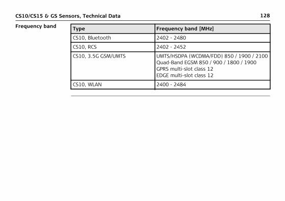
128CS10/CS15 & GS Sensors, Technical Data
Frequency band Type Frequency band [MHz]
CS10, Bluetooth 2402 - 2480
CS10, RCS 2402 - 2452
CS10, 3.5G GSM/UMTS UMTS/HSDPA (WCDMA/FDD) 850 / 1900 / 2100Quad-Band EGSM 850 / 900 / 1800 / 1900GPRS multi-slot class 12EDGE multi-slot class 12
CS10, WLAN 2400 - 2484

CS10/CS15 & GS Sensors, Technical Data 129
Output power Type Output power [mW]
CS10, Bluetooth 2.5
CS10, RCS < 100
CS10, 3.5G GSM/UMTS EGSM850/900 2
CS10, 3.5G GSM/UMTS GSM1800/1900 1
CS10, 3.5G GSM/UMTS UMTS2100 0.25
CS10, 3.5G GSM/UMTS EDGE850/900 0.5
CS10, 3.5G GSM/UMTS EDGE1800/1900 0.4
CS10, WLAN (802.11b) 50
CS10, WLAN (802.11g) 6 Mbit/s-36 Mbit/s 50
CS10, WLAN (802.11b) 48 Mbit/s-56 Mbit/s 31.6

130CS10/CS15 & GS Sensors, Technical Data
Antenna Type Antenna Gain [dBi]
Connector Frequency band [MHz]
CS10, Bluetooth Integrated antenna
- - -
CS10, RCS Integrated antenna
- - -
CS10, 3.5G GSM/UMTS Integrated antenna
- - -
CS10, WLAN Integrated antenna
- - -
GS05 Internal GNSS antenna element (receive only)
- - -
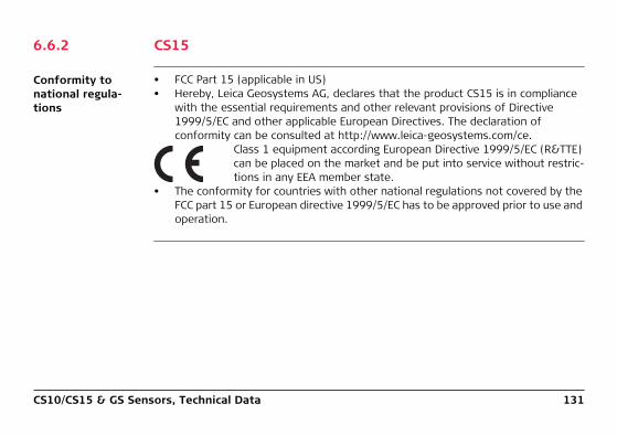
CS10/CS15 & GS Sensors, Technical Data 131
6.6.2 CS15
Conformity to national regula-tions
• FCC Part 15 (applicable in US)• Hereby, Leica Geosystems AG, declares that the product CS15 is in compliance
with the essential requirements and other relevant provisions of Directive 1999/5/EC and other applicable European Directives. The declaration of conformity can be consulted at http://www.leica-geosystems.com/ce.
Class 1 equipment according European Directive 1999/5/EC (R&TTE) can be placed on the market and be put into service without restric-tions in any EEA member state.
• The conformity for countries with other national regulations not covered by the FCC part 15 or European directive 1999/5/EC has to be approved prior to use and operation.

132CS10/CS15 & GS Sensors, Technical Data
Frequency band Type Frequency band [MHz]
CS15, Bluetooth 2402 - 2480
CS15, RCS 2402 - 2452
CS15, 3.5G GSM/UMTS UMTS/HSDPA (WCDMA/FDD) 850 / 1900 / 2100Quad-Band EGSM 850 / 900 / 1800 / 1900GPRS multi-slot class 12EDGE multi-slot class 12
CS15, WLAN 2400 - 2484

CS10/CS15 & GS Sensors, Technical Data 133
Output power Type Output power [mW]
CS15, Bluetooth 2.5
CS15, RCS < 100
CS15, 3.5G GSM/UMTS EGSM850/900 2
CS15, 3.5G GSM/UMTS GSM1800/1900 1
CS15, 3.5G GSM/UMTS UMTS2100 0.25
CS15, 3.5G GSM/UMTS EDGE850/900 0.5
CS15, 3.5G GSM/UMTS EDGE1800/1900 0.4
CS15, WLAN (802.11b) 50
CS15, WLAN (802.11g) 6 Mbit/s-36 Mbit/s 50
CS15, WLAN (802.11b) 48 Mbit/s-56 Mbit/s 31.6

134CS10/CS15 & GS Sensors, Technical Data
Antenna Type Antenna Gain [dBi]
Connector Frequency band [MHz]
CS15, Bluetooth Integrated antenna
- - -
CS15, RCS Integrated antenna
- - -
CS15, 3.5G GSM/UMTS Integrated antenna
- - -
CS15, WLAN Integrated antenna
- - -
GS06 Internal GNSS antenna element (receive only)
- - -

CS10/CS15 & GS Sensors, Technical Data 135
6.6.3 CTR16
Conformity to national regula-tions
Frequency band
Output power < 100 mW (e. i. r. p.)
Antenna
• FCC Part 15 (applicable in US)• Hereby, Leica Geosystems AG, declares that the product CTR16 is in compliance
with the essential requirements and other relevant provisions of Directive 1999/5/EC and other applicable European Directives. The declaration of conformity can be consulted at http://www.leica-geosystems.com/ce.
Class 1 equipment according European Directive 1999/5/EC (R&TTE) can be placed on the market and be put into service without restric-tions in any EEA member state.
• The conformity for countries with other national regulations not covered by the FCC part 15 or European directive 1999/5/EC has to be approved prior to use and operation.
CTR16: 2402 - 2480 MHz
Type: /2 antennaGain: 2 dBi maximalConnector: None (internal)

136CS10/CS15 & GS Sensors, Technical Data
6.6.4 GS08plus
Conformity to national regula-tions
Frequency band
• FCC Part 15, 22 and 24 (applicable in US)• Hereby, Leica Geosystems AG, declares that the product GS08plus is in compli-
ance with the essential requirements and other relevant provisions of Directive 1999/5/EC and other applicable European Directives. The declaration of conformity can be consulted at http://www.leica-geosystems.com/ce.
Class 1 equipment according European Directive 1999/5/EC (R&TTE) can be placed on the market and be put into service without restric-tions in any EEA member state.
• The conformity for countries with other national regulations not covered by the FCC part 15, 22 and 24 or European directive 1999/5/EC has to be approved prior to use and operation.
Type Frequency band [MHz]
GS08plus 1227.601575.421246.4375 - 1254.31602.4375 - 1611.5
Bluetooth 2402 - 2480
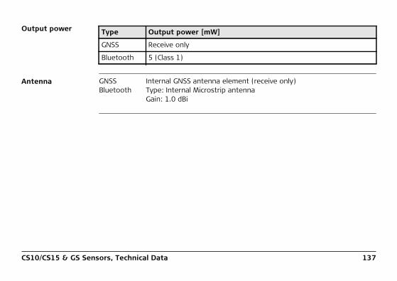
CS10/CS15 & GS Sensors, Technical Data 137
Output power
Antenna
Type Output power [mW]
GNSS Receive only
Bluetooth 5 (Class 1)
GNSS Internal GNSS antenna element (receive only)Bluetooth Type: Internal Microstrip antenna
Gain: 1.0 dBi
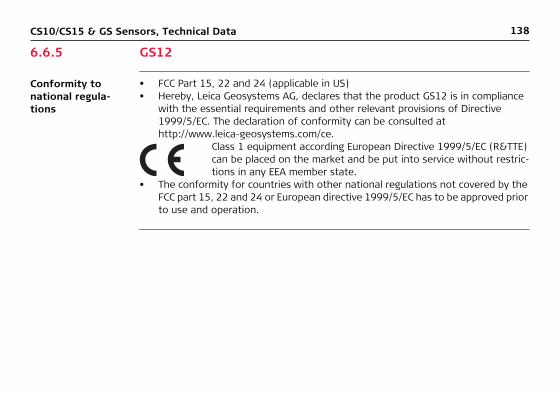
138CS10/CS15 & GS Sensors, Technical Data
6.6.5 GS12
Conformity to national regula-tions
• FCC Part 15, 22 and 24 (applicable in US)• Hereby, Leica Geosystems AG, declares that the product GS12 is in compliance
with the essential requirements and other relevant provisions of Directive 1999/5/EC. The declaration of conformity can be consulted at http://www.leica-geosystems.com/ce.
Class 1 equipment according European Directive 1999/5/EC (R&TTE) can be placed on the market and be put into service without restric-tions in any EEA member state.
• The conformity for countries with other national regulations not covered by the FCC part 15, 22 and 24 or European directive 1999/5/EC has to be approved prior to use and operation.

CS10/CS15 & GS Sensors, Technical Data 139
Frequency band
Output power
Antenna
Type Frequency band [MHz]
GS12 1176.451191.7951207.141227.601246.4375 - 1254.31575.421602.4375 - 1611.5
Bluetooth 2402 - 2480
Type Output power [mW]
GNSS Receive only
Bluetooth 5 (Class 1)
GNSS Internal GNSS antenna element (receive only)Bluetooth Type: Internal Microstrip antenna
Gain: 1.5 dBi

140CS10/CS15 & GS Sensors, Software Licence Agreement
7 Software Licence Agreement
Software Licence Agreement
This product contains software that is preinstalled on the product, or that is supplied to you on a data carrier medium, or that can be downloaded by you online according to prior authorisation from Leica Geosystems. Such software is protected by copy-right and other laws and its use is defined and regulated by the Leica Geosystems Software Licence Agreement, which covers aspects such as, but not limited to, Scope of the Licence, Warranty, Intellectual Property Rights, Limitation of Liability, Exclusion of other Assurances, Governing Law and Place of Jurisdiction. Please make sure, that at any time you fully comply with the terms and conditions of the Leica Geosystems Software Licence Agreement.
Such agreement is provided together with all products and can also be referred to and downloaded at the Leica Geosystems home page at http://www.leica-geosystems.com/swlicense or collected from your Leica Geosystems distributor.
You must not install or use the software unless you have read and accepted the terms and conditions of the Leica Geosystems Software Licence Agreement. Installa-tion or use of the software or any part thereof, is deemed to be an acceptance of all the terms and conditions of such Licence Agreement. If you do not agree to all or some of the terms of such Licence Agreement, you must not download, install or use the software and you must return the unused software together with its accompa-
CS10/CS15 & GS Sensors, Software Licence Agreement 141
nying documentation and the purchase receipt to the distributor from whom you purchased the product within ten (10) days of purchase to obtain a full refund of the purchase price.
Open source infor-mation
The software on the product may contain copyright-protected software that is licensed under various open source licences.Copies of the corresponding licences• are provided together with the product (for example in the About panel of the
software)• can be downloaded on http://opensource.leica-geosystems.com/viva/smartworxIf foreseen in the corresponding open source licence, you may obtain the corre-sponding source code and other related data on http://opensource.leica-geosystems.com/viva/smartworx.Contact [email protected] in case you need additional information.

142CS10/CS15 & GS Sensors, Pin Assignments and Sockets
Appendix A Pin Assignments and Sockets
A.1 CS10/CS15
Description Some applications require knowledge of the pin assignments for the instrument ports.In this chapter, the pin assignments and sockets for the instrument ports are explained.
Ports at the instru-ment bottom panel - DSUB9 connector
Ports at the instru-ment bottom panel - Lemo connector
a) DSUB9 portb) USB Mini portc) USB A Host portCS_022 a b c
a) Lemo port (USB and serial)b) USB A Host portCS_021 a b
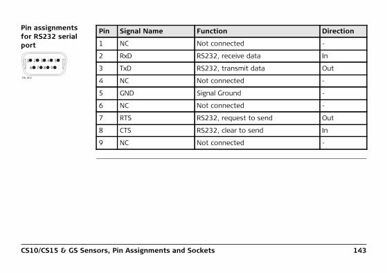
CS10/CS15 & GS Sensors, Pin Assignments and Sockets 143
Pin assignments for RS232 serial port
PIN_002
1
6 7 8 9
2 3 4 5
Pin Signal Name Function Direction
1 NC Not connected -
2 RxD RS232, receive data In
3 TxD RS232, transmit data Out
4 NC Not connected -
5 GND Signal Ground -
6 NC Not connected -
7 RTS RS232, request to send Out
8 CTS RS232, clear to send In
9 NC Not connected -
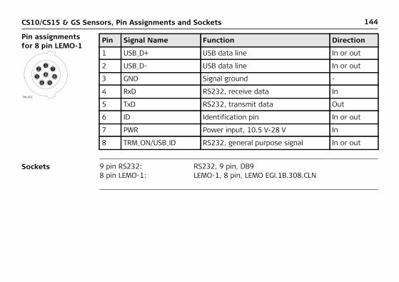
144CS10/CS15 & GS Sensors, Pin Assignments and Sockets
Pin assignments for 8 pin LEMO-1
Sockets
17
68
543
2
PIN_001
Pin Signal Name Function Direction
1 USB_D+ USB data line In or out
2 USB_D- USB data line In or out
3 GND Signal ground -
4 RxD RS232, receive data In
5 TxD RS232, transmit data Out
6 ID Identification pin In or out
7 PWR Power input, 10.5 V-28 V In
8 TRM_ON/USB_ID RS232, general purpose signal In or out
9 pin RS232: RS232, 9 pin, DB98 pin LEMO-1: LEMO-1, 8 pin, LEMO EGI.1B.308.CLN
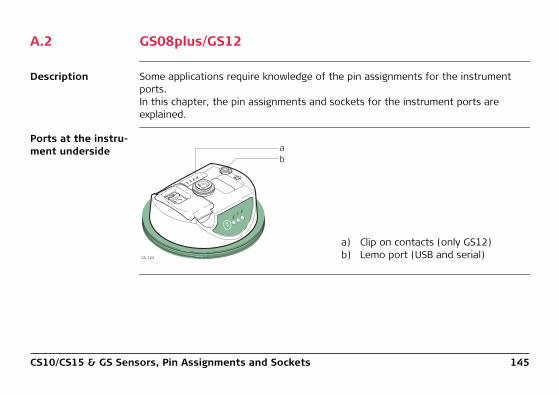
CS10/CS15 & GS Sensors, Pin Assignments and Sockets 145
A.2 GS08plus/GS12
Description Some applications require knowledge of the pin assignments for the instrument ports.In this chapter, the pin assignments and sockets for the instrument ports are explained.
Ports at the instru-ment underside
a) Clip on contacts (only GS12)b) Lemo port (USB and serial)GS_122
TR
KBTP
WR
ONOFF
ab
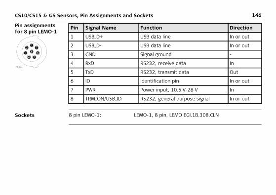
146CS10/CS15 & GS Sensors, Pin Assignments and Sockets
Pin assignments for 8 pin LEMO-1
Sockets
17
68
543
2
PIN_001
Pin Signal Name Function Direction
1 USB_D+ USB data line In or out
2 USB_D- USB data line In or out
3 GND Signal ground -
4 RxD RS232, receive data In
5 TxD RS232, transmit data Out
6 ID Identification pin In or out
7 PWR Power input, 10.5 V-28 V In
8 TRM_ON/USB_ID RS232, general purpose signal In or out
8 pin LEMO-1: LEMO-1, 8 pin, LEMO EGI.1B.308.CLN

CS10/CS15 & GS Sensors, Index 147
Index
AActiveSync ..........................................................47Antenna
CTR16 ..........................................................135Antennas ..........................................................124
GS08plus .....................................................137GS12 ............................................................139Operating Temperature ................................125Storing Temperature ....................................125Type ............................................................124
BBatteries
Charge in CS10/CS15 .....................................61Charge in GS08plus/GS12 ...............................62Charging, first-time use .................................56Operation, Discharging ..................................56
BatteryChange ..........................................................57Charge in CS10/CS15 .....................................61Internal, GS08plus ........................................121Internal, GS12 ..............................................121
Storage temperature ................................... 104Bluetooth
LED on CS10 .................................................. 67LED on CS15 .................................................. 67LED on GS08plus ........................................... 72LED on GS12 ................................................. 72
CCompactFlash card
Insert ............................................................ 63Memory device .............................................. 21Remove ......................................................... 63
ConnectorGS05 ................................................... 110, 113GS06 ................................................... 110, 113GS08plus ..................................................... 120GS12 ........................................................... 120
Connector, antennas ........................................ 124

148CS10/CS15 & GS Sensors, Index
CSAvailable models ............................................13Display foil .....................................................36Docking Station .......................................27, 43Firmware for all CS models .............................15Lock keyboard ...............................................54Operating principles .......................................35Power Options menu .....................................54Stand-by mode ..............................................54System components ......................................12Unlock keyboard ............................................54
CS10Operating temperature ................................104Status ............................................................67Storage temperature ...................................104Underside ......................................................24Upside ...........................................................23
CS15Operating temperature ................................104Status ............................................................67Storage temperature ...................................104Underside ......................................................26Upside ...........................................................25
CTR16Operating Temperature ............................... 114Storage Temperature .................................. 114
DData transfer ..................................................... 22Definition of Use ................................................ 82Description of the system .................................. 12Digital Camera .................................................... 75Dimensions
Antennas .................................................... 124GS08plus ..................................................... 120GS12 ........................................................... 120SmartAntenna ............................................. 110
Display foil ......................................................... 36Docking Station
Components .................................................. 27Mounting ....................................................... 43
Documentation .................................................... 5Drive
PC card, on office computer .......................... 22

CS10/CS15 & GS Sensors, Index 149
EElectrical data
GS08plus .....................................................122GS12 ............................................................122
Electrical DataGS05 ............................................................111GS06 ............................................................111
Electrical data, antennas ...................................125Environmental specifications
Antenna .......................................................125GS05 ............................................................112GS06 ............................................................112GS08plus .....................................................123GS12 ............................................................123
FFCC Statement ....................................................97Frequency band
GS08plus .....................................................136GS12 ............................................................139
Frequency BandCTR16 ..........................................................135
GGEB211 (internal battery)
Operating temperature ................................ 104GEB212 (internal battery)
Operating temperature ................................ 104GS
Firmware for GS05/GS06 ............................... 15Firmware for GS08plus/GS12 ......................... 15
GS05Operating Temperature ............................... 112Storage Temperature .................................. 112
GS06Operating Temperature ............................... 112Storage Temperature .................................. 112
GS08plusComponents .................................................. 28Status ........................................................... 72
GS12Components .................................................. 28Status ........................................................... 72
HHand strap ......................................................... 38Handheld GNSS .................................................. 44
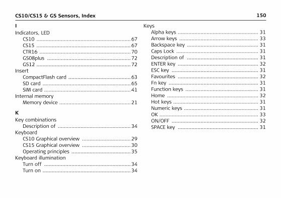
150CS10/CS15 & GS Sensors, Index
IIndicators, LED
CS10 ..............................................................67CS15 ..............................................................67CTR16 ............................................................70GS08plus .......................................................72GS12 ..............................................................72
InsertCompactFlash card .........................................63SD card ..........................................................65SIM card .........................................................41
Internal memoryMemory device ...............................................21
KKey combinations
Description of ................................................34Keyboard
CS10 Graphical overview ................................29CS15 Graphical overview ................................30Operating principles .......................................35
Keyboard illuminationTurn off .........................................................34Turn on ..........................................................34
KeysAlpha keys ..................................................... 31Arrow keys .................................................... 33Backspace key ............................................... 31Caps Lock ...................................................... 31Description of ............................................... 31ENTER key ..................................................... 32ESC key ......................................................... 31Favourites ..................................................... 32Fn key ........................................................... 31Function keys ................................................ 31Home ............................................................ 32Hot keys ........................................................ 31Numeric keys ................................................. 31OK ................................................................. 33ON/OFF ......................................................... 32SPACE key ..................................................... 31
CS10/CS15 & GS Sensors, Index 151
LLabelling
CS10 ..............................................................98CS15 ..............................................................98CTR16 ............................................................99GEB211 ........................................................100GEB212 ........................................................100GS05 ..............................................................99GS06 ..............................................................99GS08plus .....................................................100GS12 ............................................................100
LEDCS10, description ...........................................68CS15, description ...........................................68CTR15, description .........................................71GS08plus, description ....................................73GS12, description ..........................................73
Light Emitting DiodeCS10 ..............................................................67CS15 ..............................................................67CTR16 ............................................................70GS08plus .......................................................72GS12 ..............................................................72
Li-Ion battery ....................................................121
Storage ......................................................... 78
MMemory device
Available ........................................................ 21Microsoft ActiveSync .......................................... 47Mount, antennas .............................................. 124Mount, GS08plus .............................................. 120Mount, GS12 .................................................... 120
OOperating Temperature
Antennas .................................................... 125CS10 ........................................................... 104CS15 ........................................................... 104CTR16 ......................................................... 114GEB211 (internal battery) ............................ 104GEB212 (internal battery) ............................ 104GS05 ........................................................... 112GS06 ........................................................... 112GS08plus ..................................................... 123GS12 ........................................................... 123
152CS10/CS15 & GS Sensors, Index
Output powerGS08plus .....................................................137GS12 ............................................................139
Output PowerCTR16 ..........................................................135
PPC card drive on office computer ........................22Pin Assginment .................................................142Power
GS05 ............................................................111GS06 ............................................................111GS08plus .....................................................121GS12 ............................................................121
Power LEDCS10 ..............................................................67CS15 ..............................................................67GS08plus .......................................................72GS12 ..............................................................72
Power supply ......................................................19
RRadio Modem
Available radios ..............................................14Recording .........................................................104
RemoveCompactFlash card ........................................ 63SD card ......................................................... 65SIM card ........................................................ 41
ResetOptions ......................................................... 55
Responsibilities .................................................. 85Robotic setup ..................................................... 46
SSafety Directions ................................................ 81Satellite reception ............................................ 115Screen brightness
Decrease ....................................................... 34Increase ........................................................ 34
SD cardInsert ............................................................ 65Memory device .............................................. 21Remove ......................................................... 65
SIM cardInsert ............................................................ 41Remove ......................................................... 41
Slot Cover ........................................................... 40Socket .............................................................. 142
CS10/CS15 & GS Sensors, Index 153
SoftwareUpload ...........................................................16
Software Licence Agreement ............................140Specifications, environmental
Antennas .....................................................125CTR16 ..........................................................114GS05 ............................................................112GS06 ............................................................112
Status, CS10 .......................................................67Status, CS15 .......................................................67Status, CTR16 .....................................................70Status, GS08plus .................................................72Status, GS12 .......................................................72Storage Temperature
CS10 ............................................................104CS15 ............................................................104CTR16 ..........................................................114For internal battery GEB211 .........................104For internal battery GEB212 .........................104GS05 ............................................................112GS06 ............................................................112GS08plus .....................................................123GS12 ............................................................123
Storing TemperatureAntennas .................................................... 125
TTechnical Data
CS10 ........................................................... 102CS15 ........................................................... 102CTR16 ......................................................... 113Dimensions ................................................. 103Display and keyboard .................................. 102Environmental specifications ....................... 104GS05 ........................................................... 107GS06 ........................................................... 107Interface ..................................................... 105Internal battery GEB211 .............................. 104Internal battery GEB212 .............................. 104Ports ........................................................... 106Power supply ............................................... 104Weight ........................................................ 103
Temperature rangeProduct, drying .............................................. 79
Temperature, charging internal battery ............... 56

154CS10/CS15 & GS Sensors, Index
Touch screen Turn off ........................................................54 Turn on .........................................................54
Touch Screen, operating principles ......................35TPS radio LED on CTR16 ......................................70Tracking LED
GS08plus .......................................................72GS12 ..............................................................72
Transfer data ......................................................22
UUpload software .................................................16USB stick
Memory device ...............................................21User Interface .....................................................29User Manual
Validity of ........................................................4
VVolume
Decrease .......................................................34Increase .........................................................34
WWeight
Antennas .................................................... 124GS05 ........................................................... 111GS06 ........................................................... 111GS08plus ..................................................... 121GS12 ........................................................... 121
Windows CEReset registry ................................................ 55Restart .......................................................... 55
Windows Mobile Device Center ........................... 47WLAN ................................................................. 13

CS10/CS15 & GS Sensors, Index 155

Total Quality Management: Our commitment to total customer satisfaction.
Leica Geosystems AG, Heerbrugg, Switzerland, has been certified as being equipped with a quality system which meets the International Standards of Quality Management and Quality Systems (ISO standard 9001) and Environmental Management Systems (ISO standard 14001).
Ask your local Leica Geosystems dealer for more information about our TQM program.
Leica Geosystems AGHeinrich-Wild-StrasseCH-9435 HeerbruggSwitzerlandPhone +41 71 727 31 31www.leica-geosystems.com
7723
86-5
.0.0
enO
rigin
al t
ext
Prin
ted
in S
witz
erla
nd ©
201
2 Le
ica
Geo
syst
ems
AG, H
eerb
rugg
, Sw
itzer
land