Embed Size (px)
Citation preview

Leica BuilderUser Manual
Version 4.0English
2BuilderIntroduction
IntroductionPurchase Congratulations on the purchase of a Builder series instrument.
This manual contains important safety directions as well as instructions for setting up the product and operating it. Refer to "16 Safety Directions" for further informa-tion.Read carefully through the User Manual before you switch on the product.
Productidentification
The type and the serial number of your product are indicated on the type plate.Enter the type and serial number in your manual and always refer to this information when you need to contact your agency or Leica Geosystems authorized service work-shop.
Type: _______________
Serial No.: _______________
Introduction Builder 3
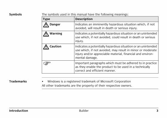
Symbols The symbols used in this manual have the following meanings:
Trademarks • Windows is a registered trademark of Microsoft CorporationAll other trademarks are the property of their respective owners.
Type Description
�Danger Indicates an imminently hazardous situation which, if not avoided, will result in death or serious injury.
�Warning Indicates a potentially hazardous situation or an unintended use which, if not avoided, could result in death or serious injury.
�Caution Indicates a potentially hazardous situation or an unintended use which, if not avoided, may result in minor or moderate injury and/or appreciable material, financial and environ-mental damage.
Important paragraphs which must be adhered to in practice as they enable the product to be used in a technically correct and efficient manner.
4BuilderIntroduction
Validity of this manual
Description
General This manual applies to all Builder instruments. Where there are differences between the various models they are clearly described.
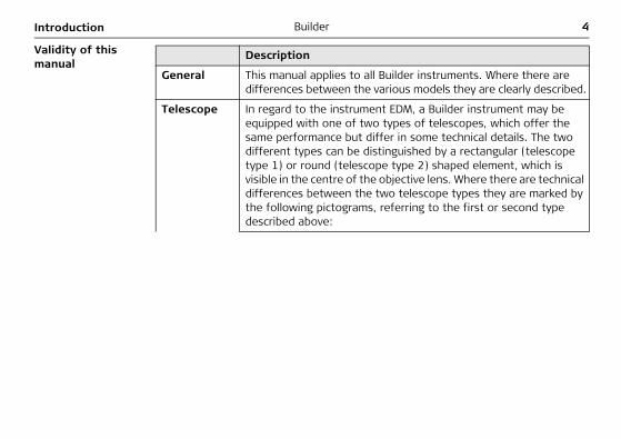
Telescope In regard to the instrument EDM, a Builder instrument may be equipped with one of two types of telescopes, which offer the same performance but differ in some technical details. The two different types can be distinguished by a rectangular (telescope type 1) or round (telescope type 2) shaped element, which is visible in the centre of the objective lens. Where there are technical differences between the two telescope types they are marked by the following pictograms, referring to the first or second type described above:
Introduction Builder 5
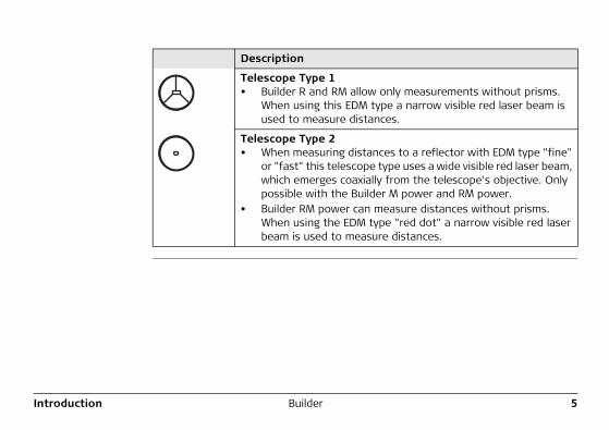
Telescope Type 1• Builder R and RM allow only measurements without prisms.
When using this EDM type a narrow visible red laser beam is used to measure distances.
Telescope Type 2• When measuring distances to a reflector with EDM type "fine"
or "fast" this telescope type uses a wide visible red laser beam, which emerges coaxially from the telescope's objective. Only possible with the Builder M power and RM power.
• Builder RM power can measure distances without prisms. When using the EDM type "red dot" a narrow visible red laser beam is used to measure distances.
Description
6BuilderTable of Contents
Table of ContentsIn this manual Chapter Page
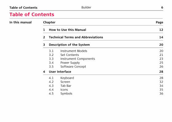
1 How to Use this Manual 12
2 Technical Terms and Abbreviations 14
3 Description of the System 20
3.1 Instrument Models 203.2 Set Contents 213.3 Instrument Components 233.4 Power Supply 253.5 Software Concept 26
4 User Interface 28
4.1 Keyboard 284.2 Screen 324.3 Tab Bar 344.4 Icons 354.5 Symbols 36
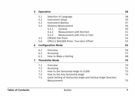
Table of Contents Builder 7
5 Operation 38
5.1 Selection of Language 385.2 Instrument Setup 395.3 Instrument Battery 475.4 Distance Measurement 50
5.4.1 General 505.4.2 Measurement with Red Dot 515.4.3 Measurement with Fine or Fast 53
5.5 CPR105 Flat Prism 545.6 CPR111 BUILDER Prism, True-Zero Offset 55
6 Configuration Mode 56
6.1 Overview 566.2 Accessing 576.3 How to Make a Setting 68
7 Theodolite Mode 70
7.1 Overview 707.2 Accessing 717.3 How to Set Horizontal Angle to 0.000 737.4 How to Set Any Horizontal Angle 747.5 Quick Setting of Horizontal Angle and Vertical Angle Direction
Measurement 75
8BuilderTable of Contents
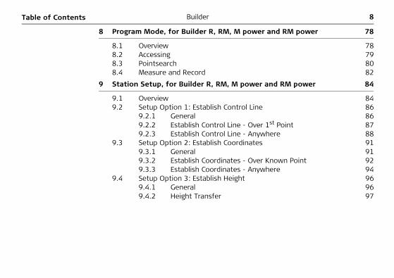
8 Program Mode, for Builder R, RM, M power and RM power 78
8.1 Overview 788.2 Accessing 798.3 Pointsearch 808.4 Measure and Record 82
9 Station Setup, for Builder R, RM, M power and RM power 84
9.1 Overview 849.2 Setup Option 1: Establish Control Line 86
9.2.1 General 869.2.2 Establish Control Line - Over 1st Point 879.2.3 Establish Control Line - Anywhere 88
9.3 Setup Option 2: Establish Coordinates 919.3.1 General 919.3.2 Establish Coordinates - Over Known Point 929.3.3 Establish Coordinates - Anywhere 94
9.4 Setup Option 3: Establish Height 969.4.1 General 969.4.2 Height Transfer 97
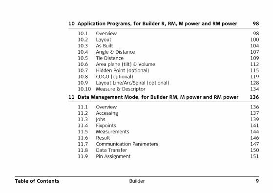
Table of Contents Builder 9
10 Application Programs, for Builder R, RM, M power and RM power 98
10.1 Overview 9810.2 Layout 10010.3 As Built 10410.4 Angle & Distance 10710.5 Tie Distance 10910.6 Area plane (tilt) & Volume 11210.7 Hidden Point (optional) 11510.8 COGO (optional) 11910.9 Layout Line/Arc/Spiral (optional) 12810.10 Measure & Descriptor 134
11 Data Management Mode, for Builder RM, M power and RM power 136
11.1 Overview 13611.2 Accessing 13711.3 Jobs 13911.4 Fixpoints 14111.5 Measurements 14411.6 Result 14611.7 Communication Parameters 14711.8 Data Transfer 15011.9 Pin Assignment 151
10BuilderTable of Contents
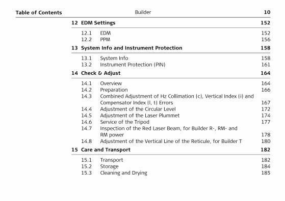
12 EDM Settings 152
12.1 EDM 15212.2 PPM 156
13 System Info and Instrument Protection 158
13.1 System Info 15813.2 Instrument Protection (PIN) 161
14 Check & Adjust 164
14.1 Overview 16414.2 Preparation 16614.3 Combined Adjustment of Hz Collimation (c), Vertical Index (i) and
Compensator Index (l, t) Errors 16714.4 Adjustment of the Circular Level 17214.5 Adjustment of the Laser Plummet 17414.6 Service of the Tripod 17714.7 Inspection of the Red Laser Beam, for Builder R-, RM- and
RM power 17814.8 Adjustment of the Vertical Line of the Reticule, for Builder T 180
15 Care and Transport 182
15.1 Transport 18215.2 Storage 18415.3 Cleaning and Drying 185
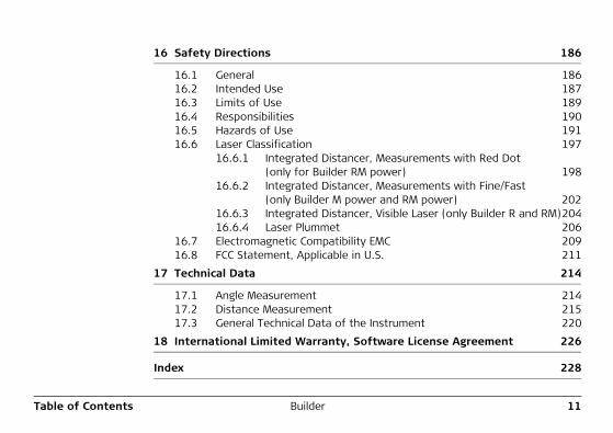
Table of Contents Builder 11
16 Safety Directions 186
16.1 General 18616.2 Intended Use 18716.3 Limits of Use 18916.4 Responsibilities 19016.5 Hazards of Use 19116.6 Laser Classification 197
16.6.1 Integrated Distancer, Measurements with Red Dot (only for Builder RM power) 198
16.6.2 Integrated Distancer, Measurements with Fine/Fast (only Builder M power and RM power) 202
16.6.3 Integrated Distancer, Visible Laser (only Builder R and RM)20416.6.4 Laser Plummet 206
16.7 Electromagnetic Compatibility EMC 20916.8 FCC Statement, Applicable in U.S. 211
17 Technical Data 214
17.1 Angle Measurement 21417.2 Distance Measurement 21517.3 General Technical Data of the Instrument 220
18 International Limited Warranty, Software License Agreement 226
Index 228
12BuilderHow to Use this Manual
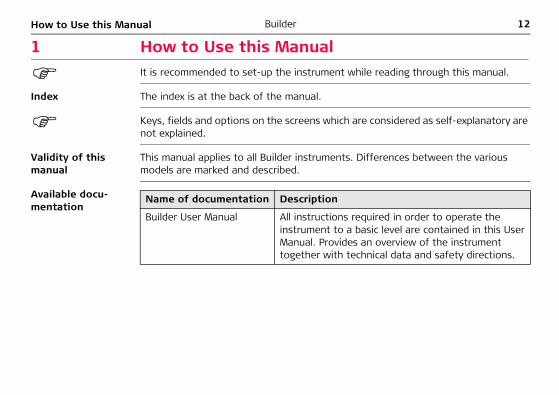
1 How to Use this ManualIt is recommended to set-up the instrument while reading through this manual.
Index The index is at the back of the manual.
Keys, fields and options on the screens which are considered as self-explanatory are not explained.
Validity of this manual
This manual applies to all Builder instruments. Differences between the various models are marked and described.
Available docu-mentation
Name of documentation Description
Builder User Manual All instructions required in order to operate the instrument to a basic level are contained in this User Manual. Provides an overview of the instrument together with technical data and safety directions.
How to Use this Manual Builder 13
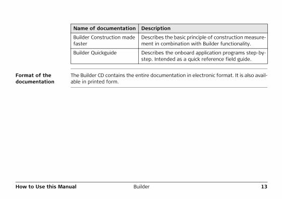
Format of the documentation
The Builder CD contains the entire documentation in electronic format. It is also avail-able in printed form.
Name of documentation Description
Builder Construction made faster
Describes the basic principle of construction measure-ment in combination with Builder functionality.
Builder Quickguide Describes the onboard application programs step-by-step. Intended as a quick reference field guide.
14BuilderTechnical Terms and Abbreviations
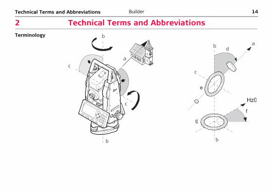
2 Technical Terms and AbbreviationsTerminology b
c
c
d
e
f
g
b
c
b b
a
a
Technical Terms and Abbreviations Builder 15
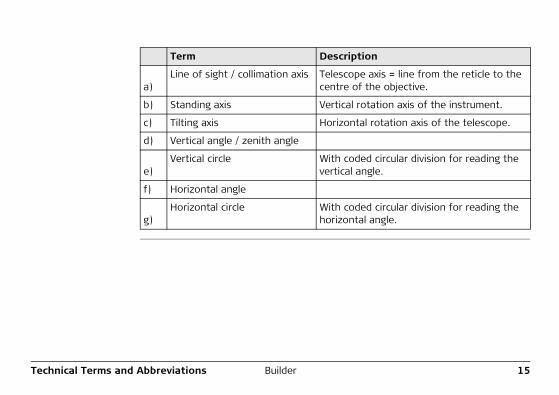
Term Description
a)Line of sight / collimation axis Telescope axis = line from the reticle to the
centre of the objective.
b) Standing axis Vertical rotation axis of the instrument.
c) Tilting axis Horizontal rotation axis of the telescope.
d) Vertical angle / zenith angle
e)Vertical circle With coded circular division for reading the
vertical angle.
f) Horizontal angle
g)Horizontal circle With coded circular division for reading the
horizontal angle.
16BuilderTechnical Terms and Abbreviations
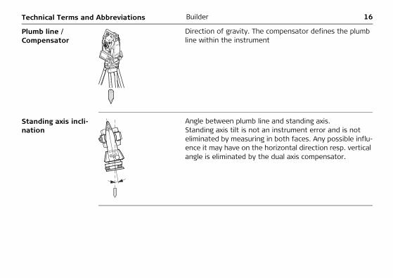
Plumb line / Compensator
Standing axis incli-nation
Direction of gravity. The compensator defines the plumb line within the instrument
Angle between plumb line and standing axis.Standing axis tilt is not an instrument error and is not eliminated by measuring in both faces. Any possible influ-ence it may have on the horizontal direction resp. vertical angle is eliminated by the dual axis compensator.
Technical Terms and Abbreviations Builder 17
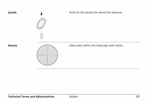
Zenith
Reticle
Point on the plumb line above the observer.
Glass plate within the telescope with reticle.
18BuilderTechnical Terms and Abbreviations
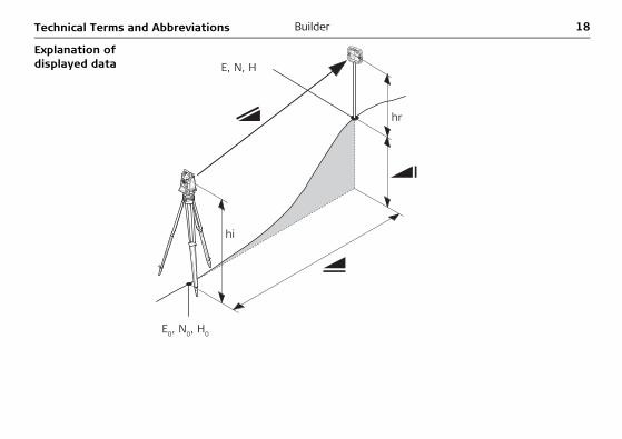
Explanation of displayed data
E0, N0, H0
E, N, H
hr
hi
Technical Terms and Abbreviations Builder 19
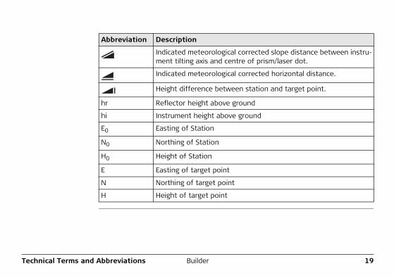
Abbreviation Description
Indicated meteorological corrected slope distance between instru-ment tilting axis and centre of prism/laser dot.
Indicated meteorological corrected horizontal distance.
Height difference between station and target point.
hr Reflector height above ground
hi Instrument height above ground
E0 Easting of Station
N0 Northing of Station
H0 Height of Station
E Easting of target point
N Northing of target point
H Height of target point
20BuilderDescription of the System
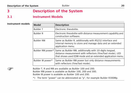
3 Description of the System3.1 Instrument Models
Instrument models
Builder T, R and RM are available as Builder 100 and 200.Builder RM power is available as Builder 100, 200 and 300.Builder M power is available as Builder 100 and 200.*) The term "power" can be abbreviated as "p", for example Builder R300Mp.
Model Description
Builder T Electronic theodolite.
Builder R Electronic theodolite with distance measurement capability and construction software.
Builder RM Same as Builder R, additionally with RS232 interface and internal memory to store and manage data and an extended application menu.
Builder RM power* Same as Builder RM, additionally with 10-digits keypad, distance measurement with reflectors (fine/fast mode), LED that shows used EDM mode and an extended application menu.
Builder M power* Same as Builder RM power but only distance measurements with reflectors (fine/fast mode).
Description of the System Builder 21
3.2 Set Contents
Set contents
b
i
k
l
m
n
j
c
d
e
f
gh
a
22BuilderDescription of the System
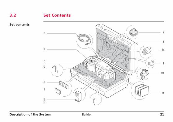
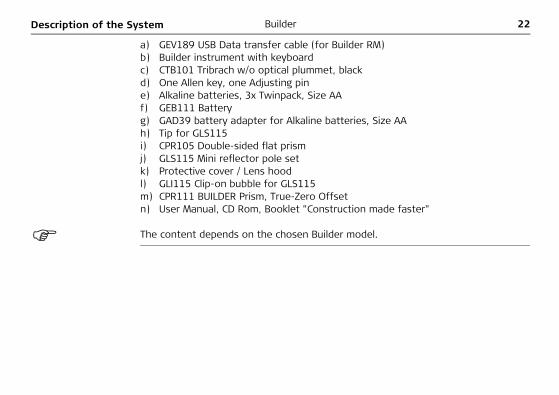
a) GEV189 USB Data transfer cable (for Builder RM)b) Builder instrument with keyboardc) CTB101 Tribrach w/o optical plummet, blackd) One Allen key, one Adjusting pine) Alkaline batteries, 3x Twinpack, Size AAf) GEB111 Batteryg) GAD39 battery adapter for Alkaline batteries, Size AAh) Tip for GLS115i) CPR105 Double-sided flat prismj) GLS115 Mini reflector pole setk) Protective cover / Lens hoodl) GLI115 Clip-on bubble for GLS115m) CPR111 BUILDER Prism, True-Zero Offsetn) User Manual, CD Rom, Booklet "Construction made faster"
The content depends on the chosen Builder model.
Description of the System Builder 23
3.3 Instrument Components
Instrument compo-nents, part 1 of 2
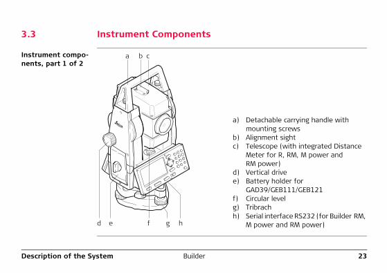
a) Detachable carrying handle with mounting screws
b) Alignment sightc) Telescope (with integrated Distance
Meter for R, RM, M power and RM power)
d) Vertical drivee) Battery holder for
GAD39/GEB111/GEB121f) Circular levelg) Tribrachh) Serial interface RS232 (for Builder RM,
M power and RM power)
a b c
ed f g h
24BuilderDescription of the System
Instrument compo-nents, part 2 of 2
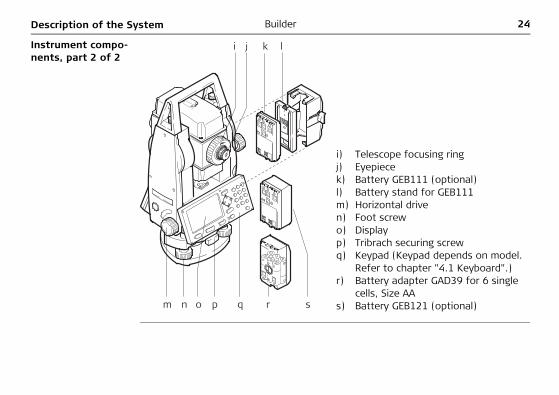
i) Telescope focusing ringj) Eyepiecek) Battery GEB111 (optional)l) Battery stand for GEB111m) Horizontal driven) Foot screwo) Displayp) Tribrach securing screwq) Keypad (Keypad depends on model.
Refer to chapter "4.1 Keyboard".)r) Battery adapter GAD39 for 6 single
cells, Size AAs) Battery GEB121 (optional)
ji k l
on p rqm s
Description of the System Builder 25
3.4 Power Supply
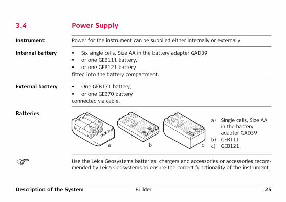
Instrument Power for the instrument can be supplied either internally or externally.
Internal battery • Six single cells, Size AA in the battery adapter GAD39, • or one GEB111 battery, • or one GEB121 battery fitted into the battery compartment.
External battery • One GEB171 battery, • or one GEB70 battery connected via cable.
Batteries
Use the Leica Geosystems batteries, chargers and accessories or accessories recom-mended by Leica Geosystems to ensure the correct functionality of the instrument.
a) Single cells, Size AA in the battery adapter GAD39
b) GEB111c) GEB121a b c
26BuilderDescription of the System
3.5 Software Concept
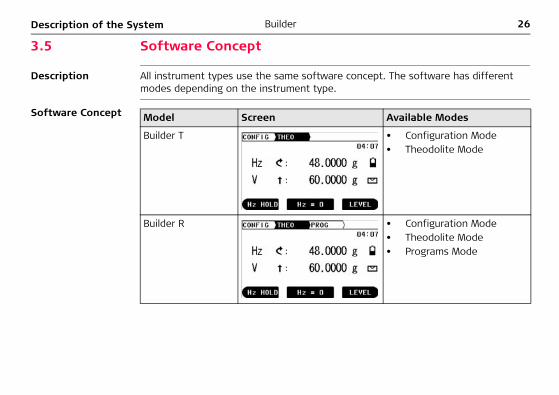
Description All instrument types use the same software concept. The software has different modes depending on the instrument type.
Software Concept Model Screen Available Modes
Builder T • Configuration Mode• Theodolite Mode
Builder R • Configuration Mode• Theodolite Mode• Programs Mode
Description of the System Builder 27
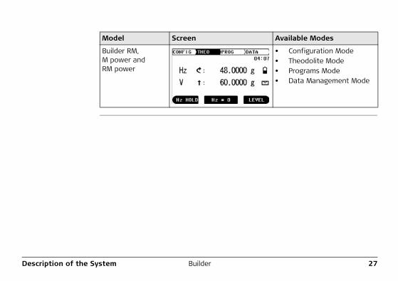
Builder RM, M power and RM power
• Configuration Mode• Theodolite Mode• Programs Mode• Data Management Mode
Model Screen Available Modes
28BuilderUser Interface
4 User Interface4.1 Keyboard
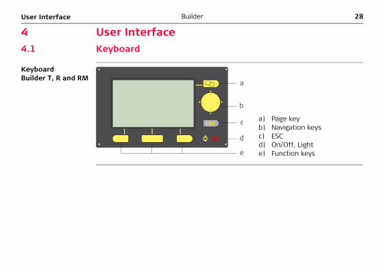
Keyboard Builder T, R and RM
a) Page keyb) Navigation keysc) ESCd) On/Off, Lighte) Function keys
a
d
e
c
b
ESC
User Interface Builder 29
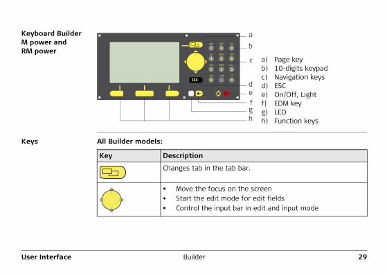
Keyboard Builder M power and RM power
Keys All Builder models:
a) Page keyb) 10-digits keypadc) Navigation keysd) ESCe) On/Off, Lightf) EDM keyg) LEDh) Function keys
a
c
b
de
gh
f
Key Description
Changes tab in the tab bar.
• Move the focus on the screen• Start the edit mode for edit fields• Control the input bar in edit and input mode
30BuilderUser Interface
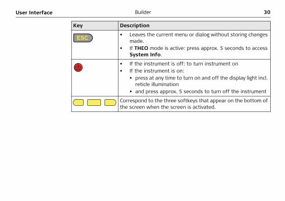
• Leaves the current menu or dialog without storing changes made.
• If THEO mode is active: press approx. 5 seconds to access System Info.
• If the instrument is off: to turn instrument on• If the instrument is on:
• press at any time to turn on and off the display light incl. reticle illumination
• and press approx. 5 seconds to turn off the instrument
Correspond to the three softkeys that appear on the bottom of the screen when the screen is activated.
Key Description
User Interface Builder 31
Only Builder M power and RM power:
Key/LED Description
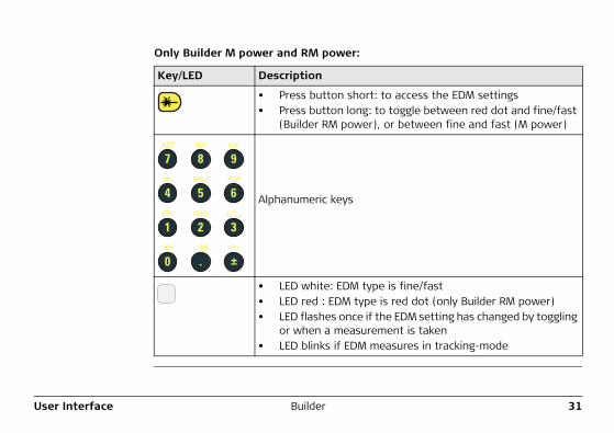
• Press button short: to access the EDM settings• Press button long: to toggle between red dot and fine/fast
(Builder RM power), or between fine and fast (M power)
Alphanumeric keys
• LED white: EDM type is fine/fast• LED red : EDM type is red dot (only Builder RM power)• LED flashes once if the EDM setting has changed by toggling
or when a measurement is taken• LED blinks if EDM measures in tracking-mode
ABC DEF GHI
JKL MNO PQR
STU VWX YZ
/$% _@& *?!
1 2 3
0 . ±
4 5 6
7 8 9
32BuilderUser Interface
4.2 Screen
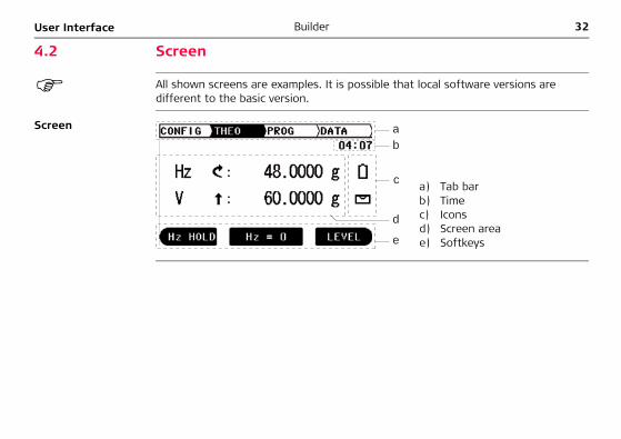
All shown screens are examples. It is possible that local software versions are different to the basic version.
Screen
a) Tab barb) Timec) Iconsd) Screen areae) Softkeys
ab
c
d
e
User Interface Builder 33
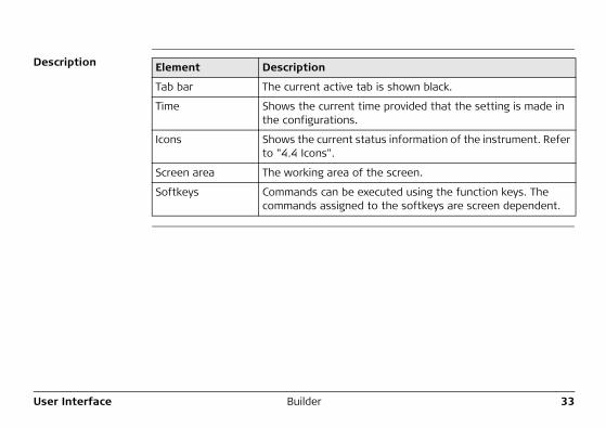
Description Element Description
Tab bar The current active tab is shown black.
Time Shows the current time provided that the setting is made in the configurations.
Icons Shows the current status information of the instrument. Refer to "4.4 Icons".
Screen area The working area of the screen.
Softkeys Commands can be executed using the function keys. The commands assigned to the softkeys are screen dependent.
34BuilderUser Interface
4.3 Tab Bar
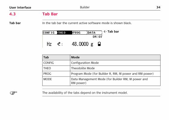
Tab bar In the tab bar the current active software mode is shown black.
The availability of the tabs depend on the instrument model.
<- Tab bar
Tab Mode
CONFIG Configuration Mode
THEO Theodolite Mode
PROG Program Mode (for Builder R, RM, M power and RM power)
MODE Data Management Mode (for Builder RM, M power and RM power)
User Interface Builder 35
4.4 Icons
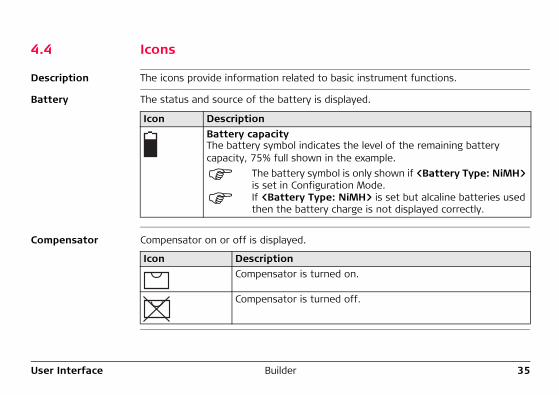
Description The icons provide information related to basic instrument functions.
Battery The status and source of the battery is displayed.
Compensator Compensator on or off is displayed.
Icon DescriptionBattery capacityThe battery symbol indicates the level of the remaining battery capacity, 75% full shown in the example.
The battery symbol is only shown if <Battery Type: NiMH> is set in Configuration Mode.If <Battery Type: NiMH> is set but alcaline batteries used then the battery charge is not displayed correctly.
Icon DescriptionCompensator is turned on.
Compensator is turned off.
36BuilderUser Interface
4.5 Symbols
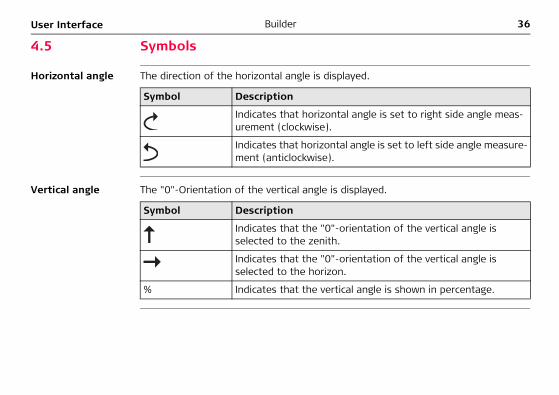
Horizontal angle The direction of the horizontal angle is displayed.
Vertical angle The "0"-Orientation of the vertical angle is displayed.
Symbol Description
Indicates that horizontal angle is set to right side angle meas-urement (clockwise).
Indicates that horizontal angle is set to left side angle measure-ment (anticlockwise).
Symbol Description
Indicates that the "0"-orientation of the vertical angle is selected to the zenith.
Indicates that the "0"-orientation of the vertical angle is selected to the horizon.
% Indicates that the vertical angle is shown in percentage.
User Interface Builder 37
Distance
Triangles
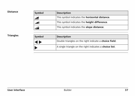
Symbol Description
This symbol indicates the horizontal distance.
This symbol indicates the height difference.
This symbol indicates the slope distance.
Symbol Description
Double triangles on the right indicate a choice field.
A single triangle on the right indicates a choice list.
38BuilderOperation
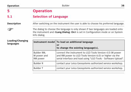
5 Operation5.1 Selection of Language
Description After switching on the instrument the user is able to choose his preferred language.
The dialog to choose the language is only shown if two languages are loaded onto the instrument and <Lang.Dialog: On> is set in Configuration mode or on System Info dialog.
Loading/Changing languages
Instrument model To load an additional languageorto change the existing language(s),
Builder RM, M power and RM power
connect the instrument to LGO Tools Version 4.0 (M power and RM power to LGO Tools Version 6.0) or higher via the serial interface and load using "LGO Tools - Software Upload".
Builder R contact your Leica Geosystems authorized service workshop.
Builder T contact your Leica Geosystems authorized service workshop.
Operation Builder 39
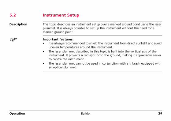
5.2 Instrument Setup
Description This topic describes an instrument setup over a marked ground point using the laser plummet. It is always possible to set up the instrument without the need for a marked ground point.
Important features:• It is always recommended to shield the instrument from direct sunlight and avoid
uneven temperatures around the instrument.• The laser plummet described in this topic is built into the vertical axis of the
instrument. It projects a red spot onto the ground, making it appreciably easier to centre the instrument.
• The laser plummet cannot be used in conjunction with a tribrach equipped with an optical plummet.
40BuilderOperation
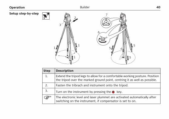
Setup step-by-step
Step Description
1. Extend the tripod legs to allow for a comfortable working posture. Position the tripod over the marked ground point, centring it as well as possible.
2. Fasten the tribrach and instrument onto the tripod.
3. Turn on the instrument by pressing the key.
The electronic level and laser plummet are activated automatically after switching on the instrument, if compensator is set to on.
2
6
7
5 4
5
51
3
1
1
Operation Builder 41
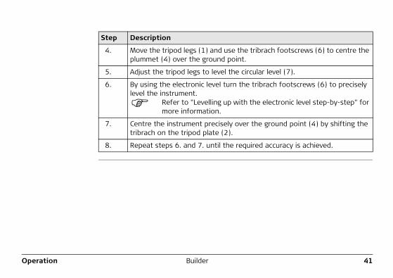
4. Move the tripod legs (1) and use the tribrach footscrews (6) to centre the plummet (4) over the ground point.
5. Adjust the tripod legs to level the circular level (7).
6. By using the electronic level turn the tribrach footscrews (6) to precisely level the instrument.
Refer to "Levelling up with the electronic level step-by-step" for more information.
7. Centre the instrument precisely over the ground point (4) by shifting the tribrach on the tripod plate (2).
8. Repeat steps 6. and 7. until the required accuracy is achieved.
Step Description
42BuilderOperation
Levelling up with the electronic level step-by-step
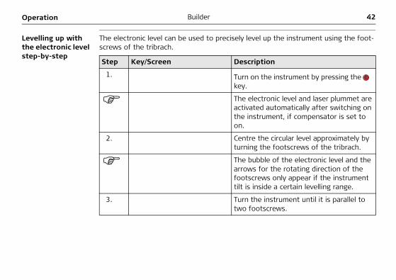
The electronic level can be used to precisely level up the instrument using the foot-screws of the tribrach.
Step Key/Screen Description
1. Turn on the instrument by pressing the key.
The electronic level and laser plummet are activated automatically after switching on the instrument, if compensator is set to on.
2. Centre the circular level approximately by turning the footscrews of the tribrach.
The bubble of the electronic level and the arrows for the rotating direction of the footscrews only appear if the instrument tilt is inside a certain levelling range.
3. Turn the instrument until it is parallel to two footscrews.
Operation Builder 43
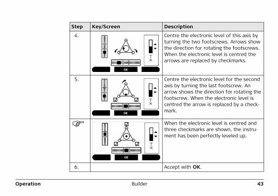
4. Centre the electronic level of this axis by turning the two footscrews. Arrows show the direction for rotating the footscrews. When the electronic level is centred the arrows are replaced by checkmarks.
5. Centre the electronic level for the second axis by turning the last footscrew. An arrow shows the direction for rotating the footscrew. When the electronic level is centred the arrow is replaced by a check-mark.
When the electronic level is centred and three checkmarks are shown, the instru-ment has been perfectly leveled up.
6. Accept with OK.
Step Key/Screen Description
44BuilderOperation
Changing the intensity of the laser plummet
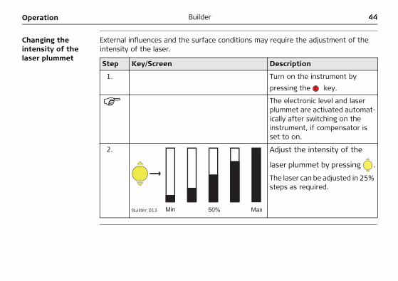
External influences and the surface conditions may require the adjustment of the intensity of the laser.
Step Key/Screen Description
1. Turn on the instrument by pressing the key.
The electronic level and laser plummet are activated automat-ically after switching on the instrument, if compensator is set to on.
2. Adjust the intensity of the
laser plummet by pressing .
The laser can be adjusted in 25% steps as required.
Builder_013
Operation Builder 45
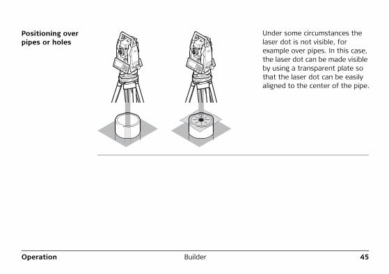
Positioning over pipes or holes
Under some circumstances the laser dot is not visible, for example over pipes. In this case, the laser dot can be made visible by using a transparent plate so that the laser dot can be easily aligned to the center of the pipe.
46BuilderOperation
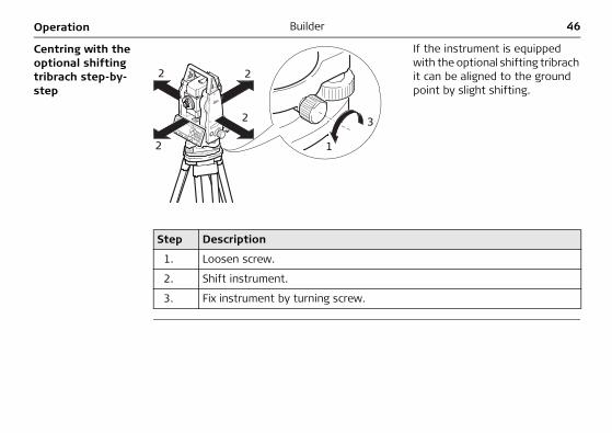
Centring with the optional shifting tribrach step-by-step
If the instrument is equipped with the optional shifting tribrach it can be aligned to the ground point by slight shifting.
Step Description
1. Loosen screw.
2. Shift instrument.
3. Fix instrument by turning screw.
1
32
2 2
2
Operation Builder 47
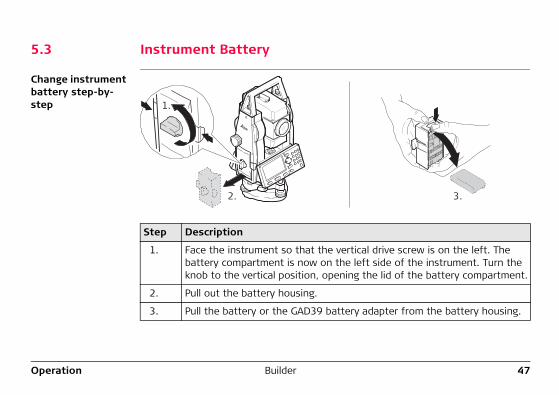
5.3 Instrument Battery
Change instrument battery step-by-step
Step Description
1. Face the instrument so that the vertical drive screw is on the left. The battery compartment is now on the left side of the instrument. Turn the knob to the vertical position, opening the lid of the battery compartment.
2. Pull out the battery housing.
3. Pull the battery or the GAD39 battery adapter from the battery housing.
1.
2. 3.
48BuilderOperation
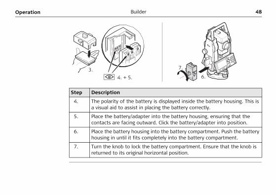
Step Description
4. The polarity of the battery is displayed inside the battery housing. This is a visual aid to assist in placing the battery correctly.
5. Place the battery/adapter into the battery housing, ensuring that the contacts are facing outward. Click the battery/adapter into position.
6. Place the battery housing into the battery compartment. Push the battery housing in until it fits completely into the battery compartment.
7. Turn the knob to lock the battery compartment. Ensure that the knob is returned to its original horizontal position.
3.6.
7.
4. + 5.
Operation Builder 49
For NiMH batteries:Charging / first-time use• The battery must be charged prior to using it for the first time because it is deliv-
ered with an energy content as low as possible.• For new batteries or batteries that have been stored for a long time (> three
months), it is effectual to make 3 - 5 charge/discharge cycles.• The permissible temperature range for charging is between 0°C to +35°C/+32°F
to +95°F. For optimal charging we recommend charging the batteries at a low ambient temperature of +10°C to +20°C/+50°F to +68°F if possible.
• It is normal for the battery to become warm during charging. Using the chargers recommended by Leica Geosystems, it is not possible to charge the battery if the temperature is too high.
Operation/Discharging• The batteries can be operated from -20°C to +55°C/-4°F to +131°F.• Low operating temperatures reduce the capacity that can be drawn; very high
operating temperatures reduce the service life of the battery.
50BuilderOperation
5.4 Distance Measurement5.4.1 General
Description A laser distancer (EDM) is incorporated into the instruments (Builder R, RM, M power and RM power) of the Builder series. In all these versions, the distance can be deter-mined by using a visible red laser beam which emerges coaxially from the telescope objective.
There are multiple EDM types:• Measurements with red dot (any surface or CPR105 flat-prism)• Measurements with fine or fast (CPR111 BUILDER prism, true-zero offset)
Available EDM types depend on the model.
In the standard version of the Builder M power and RM power, the maximum distance measurement range is 1000 m. Please refer to "12.1 EDM" on how to upgrade the measurement range.
Operation Builder 51
5.4.2 Measurement with Red Dot
Description
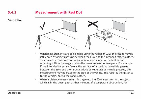
• When measurements are being made using the red laser EDM, the results may be influenced by objects passing between the EDM and the intended target surface.This occurs because red dot measurements are made to the first surface returning sufficient energy to allow the measurement to take place. For example, if the intended target surface is the surface of a road, but a vehicle passes between the EDM and the target surface as MEASURE or M&R is pressed, the measurement may be made to the side of the vehicle. The result is the distance to the vehicle, not to the road surface.
• When a distance measurement is triggered, the EDM measures to the object which is in the beam path at that moment. If a temporary obstruction, for
52BuilderOperation
example a passing vehicle, heavy rain, fog or snow is between the instrument and the point to be measured, the EDM may measure to the obstruction.
• Be sure that the laser beam is not reflected by anything close to the line of sight, for example highly reflective objects.
• When measuring longer distances, any divergence of the red laser beam from the line of sight might lead to less accurate measurements. This is because the laser beam might not be reflected from the point at which the crosshairs are pointing. Therefore, it is recommended that the visible laser beam is aligned with the center of the target. Refer to "14 Check & Adjust" for more information on how to check the alignment.
• Do not measure with two instruments to the same target simultaneously.
Guidelines for correct results:• Do not measure to glass prisms as this may lead to incorrect distance values.
Operation Builder 53
5.4.3 Measurement with Fine or Fast
Description • Accurate measurements to prisms should be made with the standard program (EDM type: fine/fast)
• Measurements to strongly reflecting targets such as to traffic lights in reflector EDM mode without prism should be avoided. The measured distances may be wrong or inaccurate.
• Very short distances may be measured reflectorless in EDM type fine/fast to well reflecting targets.
54BuilderOperation
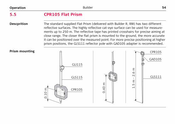
5.5 CPR105 Flat Prism
Descprition The standard supplied Flat Prism (delivered with Builder R, RM) has two different reflective surfaces. The highly reflective cat-eye surface can be used for measure-ments up to 250 m. The reflective tape has printed crosshairs for precise aiming at close range. The closer the flat prism is mounted to the ground, the more accurate it can be positioned over the measured point. For more precise positioning at higher prism positions, the GLS111 reflector pole with GAD105 adapter is recommended.
Prism mounting
0.10
m 0.40
m
CPR105
GAD105
GLS111
1.5
m -
2.6
m
GLS115
GLI115
CPR105

Operation Builder 55
5.6 CPR111 BUILDER Prism, True-Zero Offset
Description This prism with true-zero offset is only delivered with the Builder M power and RM power. The closer the prism is mounted to the ground, the more accurate it can be positioned over the measured point. For more precise positioning at higher prism positions, the GLS111 reflector pole with GAD105 adapter is recommended.
To guarantee the accuracy the prism must be aligned well. If it is not or the line of sight is very steep it is recommended to aim the middle of the yellow arrows on the prism frame.
Prism mounting
0.10
m
0.40
m
CPR111
GAD105
GLS111
1.5
m -
2.6
mGLS115
CPR111
56BuilderConfiguration Mode
6 Configuration Mode6.1 Overview
Description The CONFIG mode is used for:• creating user specific settings in order to adapt the instrument to your own
requirements• setting date and time• setting units
Descriptions apply in general to Builder R, RM, M power and RM power. Available options depend on the model.
Configuration Mode Builder 57
6.2 Accessing
Access step-by-step
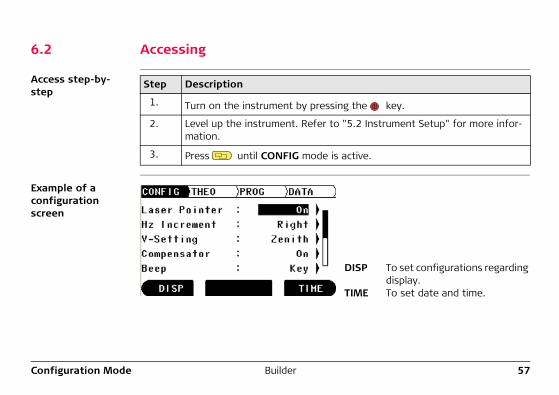
Example of a configuration screen
Step Description
1. Turn on the instrument by pressing the key.
2. Level up the instrument. Refer to "5.2 Instrument Setup" for more infor-mation.
3. Press until CONFIG mode is active.
DISP To set configurations regarding display.
TIME To set date and time.
58BuilderConfiguration Mode
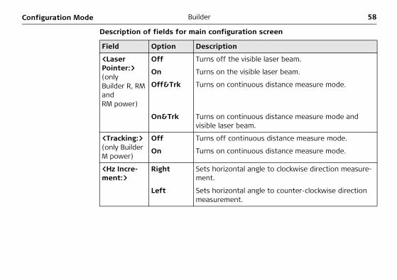
Description of fields for main configuration screen
Field Option Description
<Laser Pointer:>(only Builder R, RM and RM power)
Off Turns off the visible laser beam.
On Turns on the visible laser beam.
Off&Trk Turns on continuous distance measure mode.
On&Trk Turns on continuous distance measure mode and visible laser beam.
<Tracking:> (only Builder M power)
Off Turns off continuous distance measure mode.
On Turns on continuous distance measure mode.
<Hz Incre-ment:>
Right Sets horizontal angle to clockwise direction measure-ment.
Left Sets horizontal angle to counter-clockwise direction measurement.
Configuration Mode Builder 59
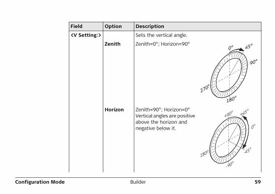
<V Setting:> Sets the vertical angle.
Zenith Zenith=0°; Horizon=90°
Horizon Zenith=90°; Horizon=0°Vertical angles are positive above the horizon and negative below it.
Field Option Description
90°
270°
180°
0° 45°
180°
+90°
-90°
+45°
-45°
0°
60BuilderConfiguration Mode
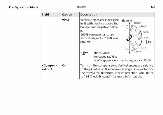
V(%) Vertical angles are expressed in % with positive above the horizon and negative below it.100% corresponds to an vertical angle of 45° (50 gon, 800 mil).
The % value increases rapidly. --.--% appears on the display above 300%.
<Compen-sator:>
On Turns on the compensator. Vertical angles are relative to the plumb line. The horizontal angle is corrected for the transversal tilt errors, if <Hz Correction: On>. Refer to "14 Check & Adjust" for more information.
Field Option Description
Slope %+300 %
+100%
+18 %
0°
-100 %
-300 %
20°
45°
71°3
4”
360sgon-50 gon
-79,5 gon
--.--%
--.--%
±V
Configuration Mode Builder 61
Off Turns off the compensator. Vertical angles are relative to vertical/standing axis.
If the instrument is used on an unstable base e.g.shaking platform, ship, etc. the compensator should be switched off. This avoids the compensator drifting out of its measuring range and interrupting the measuring process by indicating an error.
The compensator setting remains active even after the instrument is switched off.
<Beep:> Off Turns key beep and sector beep off.
Key Turns only key beep on.
Key&Sect Turns key beep and sector beep on. Turns layout beep in Layout application on.
Sector Turns sector beep on. Turns layout beep in Layout application on.
Field Option Description
62BuilderConfiguration Mode
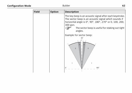
The key beep is an acoustic signal after each keystroke.The sector beep is an acoustic signal which sounds if horizontal angle is 0°, 90°, 180°, 270° or 0, 100, 200, 300 gon.
The sector beep is useful for staking out right angles.
Example for sector beep:
Field Option Description
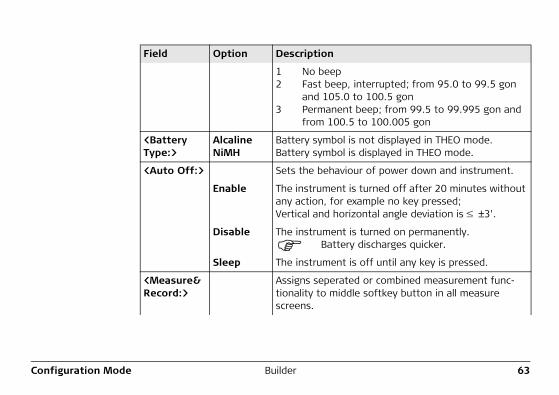
Configuration Mode Builder 63
1 No beep2 Fast beep, interrupted; from 95.0 to 99.5 gon
and 105.0 to 100.5 gon3 Permanent beep; from 99.5 to 99.995 gon and
from 100.5 to 100.005 gon
<Battery Type:>
AlcalineNiMH
Battery symbol is not displayed in THEO mode.Battery symbol is displayed in THEO mode.
<Auto Off:> Sets the behaviour of power down and instrument.
Enable The instrument is turned off after 20 minutes without any action, for example no key pressed;Vertical and horizontal angle deviation is ±3'.
Disable The instrument is turned on permanently.Battery discharges quicker.
Sleep The instrument is off until any key is pressed.
<Measure&Record:>
Assigns seperated or combined measurement func-tionality to middle softkey button in all measure screens.
Field Option Description
64BuilderConfiguration Mode
Description of fields for display configuration screen
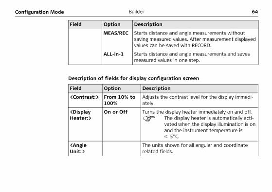
MEAS/REC Starts distance and angle measurements without saving measured values. After measurement displayed values can be saved with RECORD.
ALL-in-1 Starts distance and angle measurements and saves measured values in one step.
Field Option Description
<Contrast:> From 10% to 100%
Adjusts the contrast level for the display immedi-ately.
<Display Heater:>
On or Off Turns the display heater immediately on and off.The display heater is automatically acti-vated when the display illumination is on and the instrument temperature is
5°C.
<Angle Unit:>
The units shown for all angular and coordinate related fields.
Field Option Description
Configuration Mode Builder 65
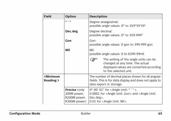
° ' " Degree sexagesimal:possible angle values: 0° to 359°59'59''
Dec.deg Degree decimal:possible angle values: 0° to 359.999°
Gon Gon:possible angle values: 0 gon to 399.999 gon
Mil Mil:possible angle values: 0 to 6399.99mil
The setting of the angle units can be changed at any time. The actual displayed values are converted according to the selected unit.
<Minimum Reading:>
The number of decimal places shown for all angular fields. This is for data display and does not apply to data export or storage.
Precise (only 200M power, R200M power, R300M power)
0° 00' 01" for <Angle Unit: ° ' ''>.0.0001 for <Angle Unit: Gon> and <Angle Unit: Dec.deg>.0.01 for <Angle Unit: Mil>.
Field Option Description
66BuilderConfiguration Mode
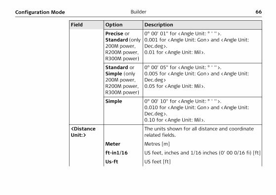
Precise or Standard (only 200M power, R200M power, R300M power)
0° 00' 01" for <Angle Unit: ° ' ''>.0.001 for <Angle Unit: Gon> and <Angle Unit: Dec.deg>.0.01 for <Angle Unit: Mil>.
Standard or Simple (only 200M power, R200M power, R300M power)
0° 00' 05" for <Angle Unit: ° ' ''>.0.005 for <Angle Unit: Gon> and <Angle Unit: Dec.deg>0.05 for <Angle Unit: Mil>.
Simple 0° 00' 10" for <Angle Unit: ° ' ''>.0.010 for <Angle Unit: Gon> and <Angle Unit: Dec.deg>.0.10 for <Angle Unit: Mil>.
<Distance Unit:>
The units shown for all distance and coordinate related fields.
Meter Metres [m]
ft-in1/16 US feet, inches and 1/16 inches (0' 00 0/16 fi) [ft]
Us-ft US feet [ft]
Field Option Description
Configuration Mode Builder 67
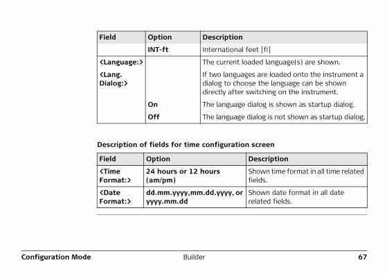
Description of fields for time configuration screen
INT-ft International feet [fi]
<Language:> The current loaded language(s) are shown.
<Lang.Dialog:>
If two languages are loaded onto the instrument a dialog to choose the language can be shown directly after switching on the instrument.
On The language dialog is shown as startup dialog.
Off The language dialog is not shown as startup dialog.
Field Option Description
<Time Format:>
24 hours or 12 hours (am/pm)
Shown time format in all time related fields.
<Date Format:>
dd.mm.yyyy,mm.dd.yyyy, or yyyy.mm.dd
Shown date format in all date related fields.
Field Option Description
68BuilderConfiguration Mode
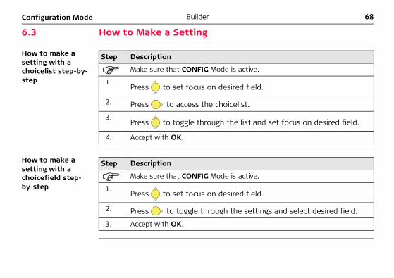
6.3 How to Make a Setting
How to make a setting with a choicelist step-by-step
How to make a setting with a choicefield step-by-step
Step Description
Make sure that CONFIG Mode is active.
1.Press to set focus on desired field.
2. Press to access the choicelist.
3.Press to toggle through the list and set focus on desired field.
4. Accept with OK.
Step Description
Make sure that CONFIG Mode is active.
1.Press to set focus on desired field.
2. Press to toggle through the settings and select desired field.
3. Accept with OK.
Configuration Mode Builder 69
70BuilderTheodolite Mode
7 Theodolite Mode7.1 Overview
Description The THEO mode is used for:• levelling up the instrument with the electronic level and adjusting the intensity of
the laser plummet• reading off the current horizontal and vertical angle• setting horizontal angle to zero• setting any horizontal angle• quick setting of horizontal and vertical angle direction
Theodolite Mode Builder 71
7.2 Accessing
Access step-by-step
Example of a theodolite screen
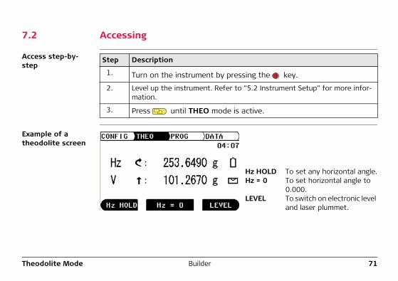
Step Description
1. Turn on the instrument by pressing the key.
2. Level up the instrument. Refer to "5.2 Instrument Setup" for more infor-mation.
3. Press until THEO mode is active.
Hz HOLD To set any horizontal angle.Hz = 0 To set horizontal angle to
0.000.LEVEL To switch on electronic level
and laser plummet.
72BuilderTheodolite Mode
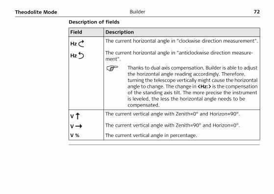
Description of fields
Field Description
Hz The current horizontal angle in "clockwise direction measurement".
Hz The current horizontal angle in "anticlockwise direction measure-ment".
Thanks to dual axis compensation, Builder is able to adjust the horizontal angle reading accordingly. Therefore, turning the telescope vertically might cause the horizontal angle to change. The change in <Hz:> is the compensation of the standing axis tilt. The more precise the instrument is leveled, the less the horizontal angle needs to be compensated.
V The current vertical angle with Zenith=0° and Horizon=90°.
V The current vertical angle with Zenith=90° and Horizon=0°.
V % The current vertical angle in percentage.
Theodolite Mode Builder 73
7.3 How to Set Horizontal Angle to 0.000
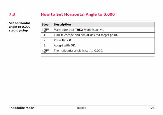
Set horizontal angle to 0.000 step-by-step
Step Description
Make sure that THEO Mode is active.
1. Turn telescope and aim at desired target point.
2. Press Hz = 0.
3. Accept with OK.
The horizontal angle is set to 0.000.
74BuilderTheodolite Mode
7.4 How to Set Any Horizontal Angle
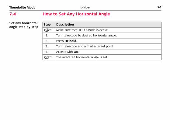
Set any horizontal angle step-by-step
Step Description
Make sure that THEO Mode is active.
1. Turn telescope to desired horizontal angle.
2. Press Hz hold.
3. Turn telescope and aim at a target point.
4. Accept with OK.
The indicated horizontal angle is set.
Theodolite Mode Builder 75
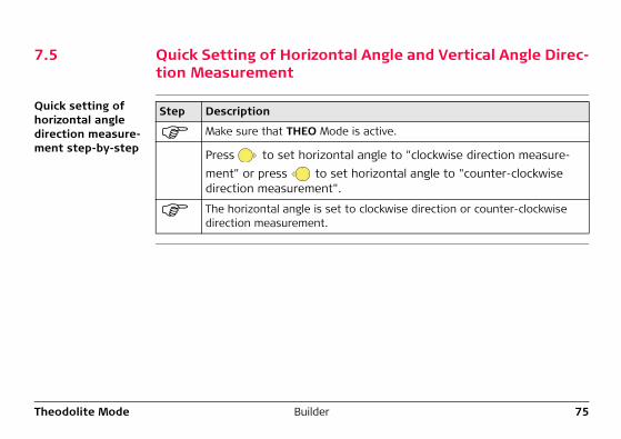
7.5 Quick Setting of Horizontal Angle and Vertical Angle Direc-tion Measurement
Quick setting of horizontal angle direction measure-ment step-by-step
Step Description
Make sure that THEO Mode is active.
Press to set horizontal angle to "clockwise direction measure-ment" or press to set horizontal angle to "counter-clockwise direction measurement".
The horizontal angle is set to clockwise direction or counter-clockwise direction measurement.
76BuilderTheodolite Mode
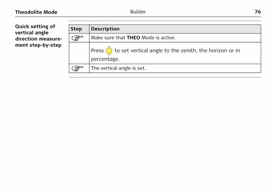
Quick setting of vertical angle direction measure-ment step-by-step
Step Description
Make sure that THEO Mode is active.
Press to set vertical angle to the zenith, the horizon or in percentage.
The vertical angle is set.

Theodolite Mode Builder 77
78BuilderProgram Mode, for Builder R, RM, M power and RM power
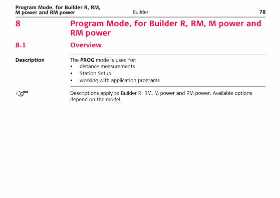
8 Program Mode, for Builder R, RM, M power and RM power
8.1 Overview
Description The PROG mode is used for:• distance measurements• Station Setup• working with application programs
Descriptions apply to Builder R, RM, M power and RM power. Available options depend on the model.
Program Mode, for Builder R, RM, M power and RM power
Builder 79
8.2 Accessing
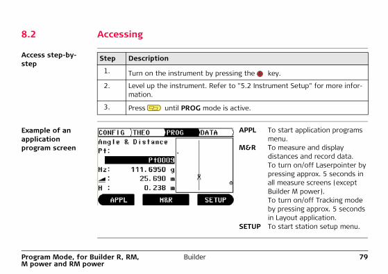
Access step-by-step
Example of an application program screen
Step Description
1. Turn on the instrument by pressing the key.
2. Level up the instrument. Refer to "5.2 Instrument Setup" for more infor-mation.
3. Press until PROG mode is active.
APPL To start application programs menu.
M&R To measure and display distances and record data.To turn on/off Laserpointer by pressing approx. 5 seconds in all measure screens (except Builder M power).To turn on/off Tracking mode by pressing approx. 5 seconds in Layout application.
SETUP To start station setup menu.
80BuilderProgram Mode, for Builder R, RM, M power and RM power
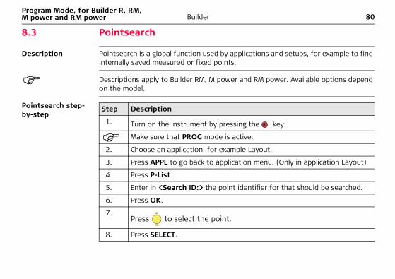
8.3 Pointsearch
Description Pointsearch is a global function used by applications and setups, for example to find internally saved measured or fixed points.
Descriptions apply to Builder RM, M power and RM power. Available options depend on the model.
Pointsearch step-by-step
Step Description
1. Turn on the instrument by pressing the key.
Make sure that PROG mode is active.
2. Choose an application, for example Layout.
3. Press APPL to go back to application menu. (Only in application Layout)
4. Press P-List.
5. Enter in <Search ID:> the point identifier for that should be searched.
6. Press OK.
7.Press to select the point.
8. Press SELECT.
Program Mode, for Builder R, RM, M power and RM power
Builder 81
Example of a Pointsearch screen
Description of fields
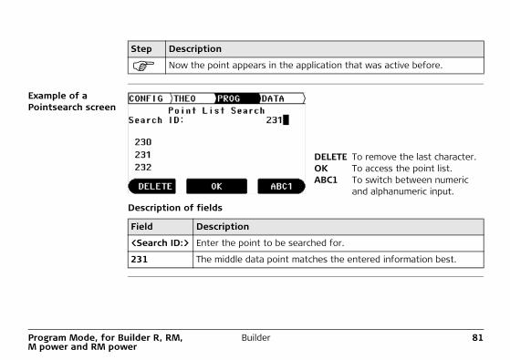
Now the point appears in the application that was active before.
Step Description
DELETE To remove the last character.OK To access the point list.ABC1 To switch between numeric
and alphanumeric input.
Field Description
<Search ID:> Enter the point to be searched for.
231 The middle data point matches the entered information best.
82BuilderProgram Mode, for Builder R, RM, M power and RM power
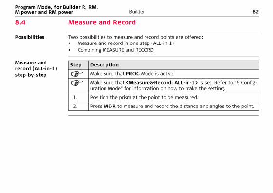
8.4 Measure and Record
Possibilities Two possibilities to measure and record points are offered:• Measure and record in one step (ALL-in-1)• Combining MEASURE and RECORD
Measure and record (ALL-in-1) step-by-step
Step Description
Make sure that PROG Mode is active.
Make sure that <Measure&Record: ALL-in-1> is set. Refer to "6 Config-uration Mode" for information on how to make the setting.
1. Position the prism at the point to be measured.
2. Press M&R to measure and record the distance and angles to the point.
Program Mode, for Builder R, RM, M power and RM power
Builder 83
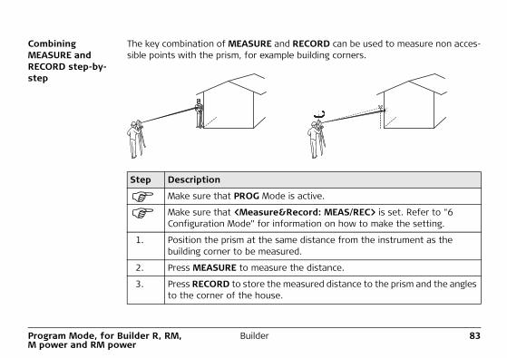
Combining MEASURE and RECORD step-by-step
The key combination of MEASURE and RECORD can be used to measure non acces-sible points with the prism, for example building corners.
Step Description
Make sure that PROG Mode is active.
Make sure that <Measure&Record: MEAS/REC> is set. Refer to "6 Configuration Mode" for information on how to make the setting.
1. Position the prism at the same distance from the instrument as the building corner to be measured.
2. Press MEASURE to measure the distance.
3. Press RECORD to store the measured distance to the prism and the angles to the corner of the house.
84BuilderStation Setup, for Builder R, RM, M power and RM power
9 Station Setup, for Builder R, RM, M power and RM power
9.1 Overview
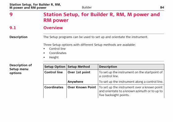
Description The Setup programs can be used to set up and orientate the instrument.
Three Setup options with different Setup methods are available:• Control line• Coordinates• Height
Description of Setup menu options
Setup Option Setup Method Description
Control line Over 1st point To set up the instrument on the startpoint of a control line.
Anywhere To set up the instrument along a control line.
Coordinates Over Known Point To set up the instrument over a known point and orientate to a known azimuth or to up to five backsight points.
Station Setup, for Builder R, RM, M power and RM power
Builder 85
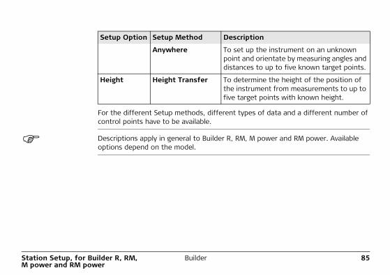
For the different Setup methods, different types of data and a different number of control points have to be available.
Descriptions apply in general to Builder R, RM, M power and RM power. Available options depend on the model.
Anywhere To set up the instrument on an unknown point and orientate by measuring angles and distances to up to five known target points.
Height Height Transfer To determine the height of the position of the instrument from measurements to up to five target points with known height.
Setup Option Setup Method Description
86BuilderStation Setup, for Builder R, RM, M power and RM power
9.2 Setup Option 1: Establish Control Line9.2.1 General
Description The Setup Option Control Line is used to set up the instrument in relation to a control line. All further measuring points and points to be staked are in relation to the control line.
Station Setup, for Builder R, RM, M power and RM power
Builder 87
9.2.2 Establish Control Line - Over 1st Point
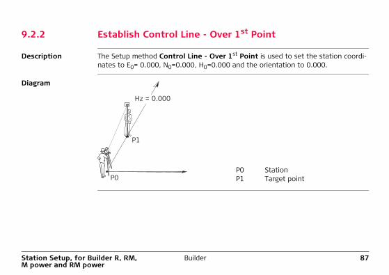
Description The Setup method Control Line - Over 1st Point is used to set the station coordi-nates to E0= 0.000, N0=0.000, H0=0.000 and the orientation to 0.000.
Diagram
P0 StationP1 Target point
P1
P0
Hz = 0.000
88BuilderStation Setup, for Builder R, RM, M power and RM power
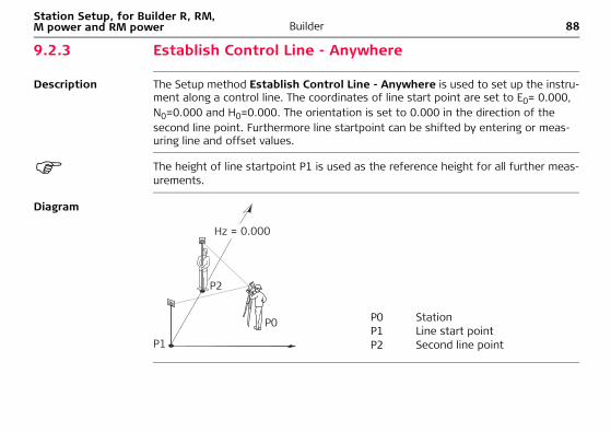
9.2.3 Establish Control Line - Anywhere
Description The Setup method Establish Control Line - Anywhere is used to set up the instru-ment along a control line. The coordinates of line start point are set to E0= 0.000, N0=0.000 and H0=0.000. The orientation is set to 0.000 in the direction of the second line point. Furthermore line startpoint can be shifted by entering or meas-uring line and offset values.
The height of line startpoint P1 is used as the reference height for all further meas-urements.
Diagram
P0 StationP1 Line start pointP2 Second line point
P2
P1
P0
Hz = 0.000
Station Setup, for Builder R, RM, M power and RM power
Builder 89
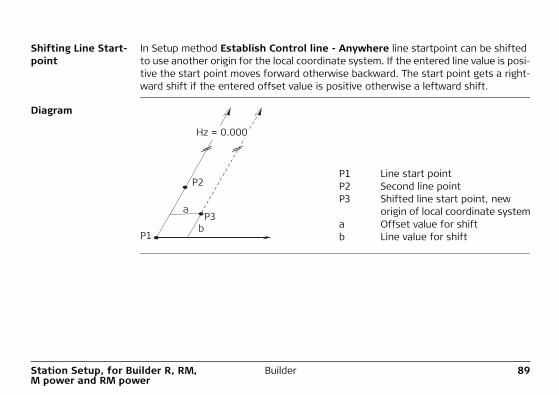
Shifting Line Start-point
In Setup method Establish Control line - Anywhere line startpoint can be shifted to use another origin for the local coordinate system. If the entered line value is posi-tive the start point moves forward otherwise backward. The start point gets a right-ward shift if the entered offset value is positive otherwise a leftward shift.
Diagram
P1 Line start pointP2 Second line pointP3 Shifted line start point, new
origin of local coordinate systema Offset value for shift b Line value for shift
P2
P3b
a
P1
Hz = 0.000
90BuilderStation Setup, for Builder R, RM, M power and RM power
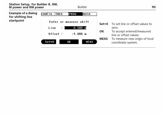
Example of a dialog for shifting line startpoint
Set=0 To set line or offset values to zero.
OK To accept entered/measured line or offset values.
MEAS To measure new origin of local coordinate system.
Station Setup, for Builder R, RM, M power and RM power
Builder 91
9.3 Setup Option 2: Establish Coordinates9.3.1 General
Description The Setup Option Coordinates is used to set up the instrument in relation to a local or global coordinate system. All further measuring points and points to be staked are in relation to the coordinate system.
92BuilderStation Setup, for Builder R, RM, M power and RM power
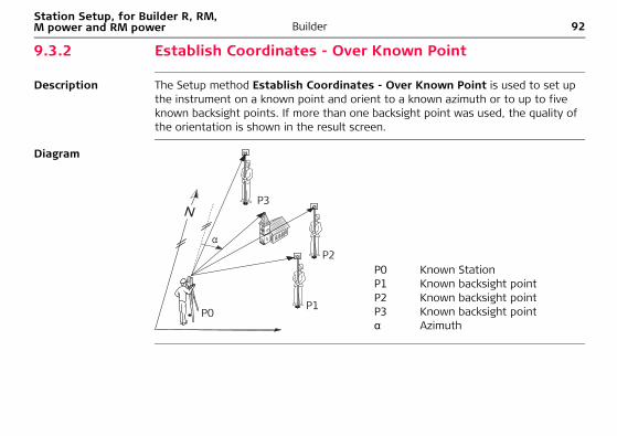
9.3.2 Establish Coordinates - Over Known Point
Description The Setup method Establish Coordinates - Over Known Point is used to set up the instrument on a known point and orient to a known azimuth or to up to five known backsight points. If more than one backsight point was used, the quality of the orientation is shown in the result screen.
Diagram
P0 Known StationP1 Known backsight pointP2 Known backsight pointP3 Known backsight pointα Azimuth
P1
P2
P3
P0
Station Setup, for Builder R, RM, M power and RM power
Builder 93
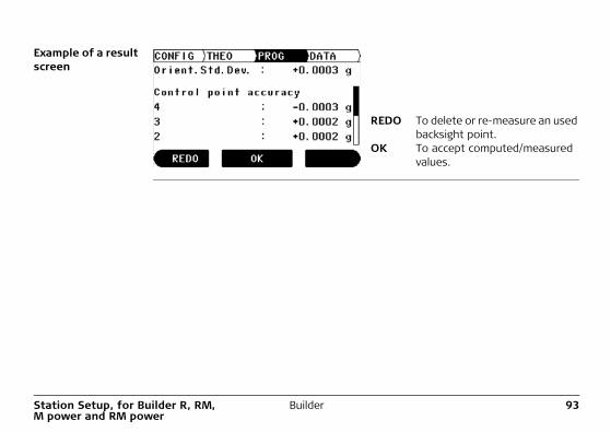
Example of a result screen
REDO To delete or re-measure an used backsight point.
OK To accept computed/measured values.
94BuilderStation Setup, for Builder R, RM, M power and RM power
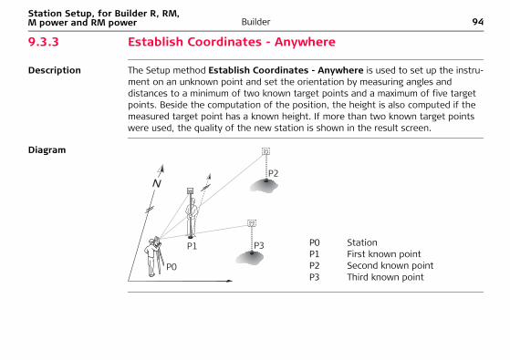
9.3.3 Establish Coordinates - Anywhere
Description The Setup method Establish Coordinates - Anywhere is used to set up the instru-ment on an unknown point and set the orientation by measuring angles and distances to a minimum of two known target points and a maximum of five target points. Beside the computation of the position, the height is also computed if the measured target point has a known height. If more than two known target points were used, the quality of the new station is shown in the result screen.
Diagram
P0 StationP1 First known pointP2 Second known pointP3 Third known point
P0
P1
P2
P3
Station Setup, for Builder R, RM, M power and RM power
Builder 95
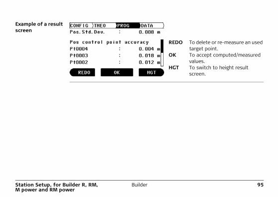
Example of a result screen
REDO To delete or re-measure an used target point.
OK To accept computed/measured values.
HGT To switch to height result screen.
96BuilderStation Setup, for Builder R, RM, M power and RM power
9.4 Setup Option 3: Establish Height9.4.1 General
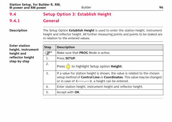
Description The Setup Option Establish Height is used to enter the station height, instrument height and reflector height. All further measuring points and points to be staked are in relation to the entered values.
Enter station height, instrument height and reflector height step-by-step
Step Description
Make sure that PROG Mode is active.
1. Press SETUP.
2.Press to highlight Setup option Height.
3. If a value for station height is shown, the value is related to the chosen setup method of Control Line or Coordinates. This value may be changed or in case of <-----.---->, a height can be entered.
4. Enter station height, instrument height and reflector height.
5. Accept with OK.
Station Setup, for Builder R, RM, M power and RM power
Builder 97
9.4.2 Height Transfer
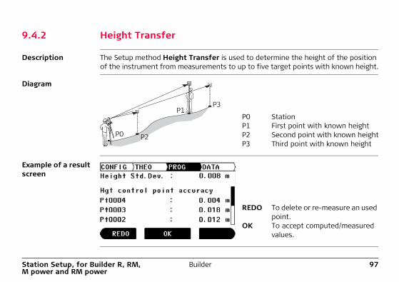
Description The Setup method Height Transfer is used to determine the height of the position of the instrument from measurements to up to five target points with known height.
Diagram
Example of a result screen
P0 StationP1 First point with known heightP2 Second point with known heightP3 Third point with known height
P1
P0
P3
P2
REDO To delete or re-measure an used point.
OK To accept computed/measured values.
98BuilderApplication Programs, for Builder R, RM, M power and RM power
10 Application Programs, for Builder R, RM, M power and RM power
10.1 Overview
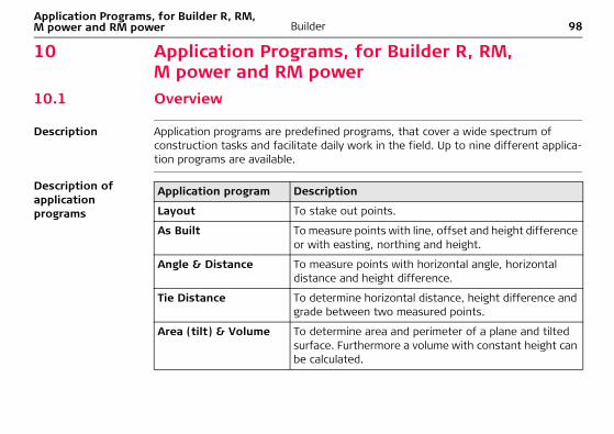
Description Application programs are predefined programs, that cover a wide spectrum of construction tasks and facilitate daily work in the field. Up to nine different applica-tion programs are available.
Description of application programs
Application program Description
Layout To stake out points.
As Built To measure points with line, offset and height difference or with easting, northing and height.
Angle & Distance To measure points with horizontal angle, horizontal distance and height difference.
Tie Distance To determine horizontal distance, height difference and grade between two measured points.
Area (tilt) & Volume To determine area and perimeter of a plane and tilted surface. Furthermore a volume with constant height can be calculated.
Application Programs, for Builder R, RM, M power and RM power
Builder 99
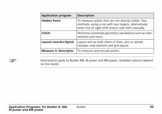
Descriptions apply to Builder RM, M power and RM power. Available options depend on the model.
Hidden Point To measure points that are not directly visible. Two methods: using a rod with two targets, alternatively enter line of sight shift and/or side shift manually.
COGO Performs coordinate geometry calculations such as inter-sections and more.
Layout Line/Arc/Spiral Layout and as-built check of lines, arcs or spirals. Includes road element and grid layout.
Measure & Descriptor To measure and encode points.
Application program Description

100BuilderApplication Programs, for Builder R, RM, M power and RM power
10.2 Layout
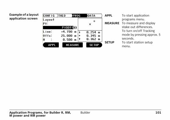
Description The application program Layout is used to place markers in the field at predeter-mined points. These predetermined points are the points to be staked. The points to be staked are defined by entering line and offset or easting, northing and height depending on the used setup method. For Builder RM, M and RM power the points can also be selected from the memory. The program calculates and displays the difference between the measured point and the point to be staked.
Diagram
P0 StationP1 Current positionP2 Point to be stakedd1 < :> go forward or < :> go backd2 < :> go right or < :> leftd3 < :> fill or < :> cutP0
P1
P2
d2 d3
d1
Application Programs, for Builder R, RM, M power and RM power
Builder 101
Example of a layout application screen
APPL To start application programs menu.
MEASURE To measure and display stake out differences.To turn on/off Tracking mode by pressing approx. 5 seconds.
SETUP To start station setup menu.
102BuilderApplication Programs, for Builder R, RM, M power and RM power
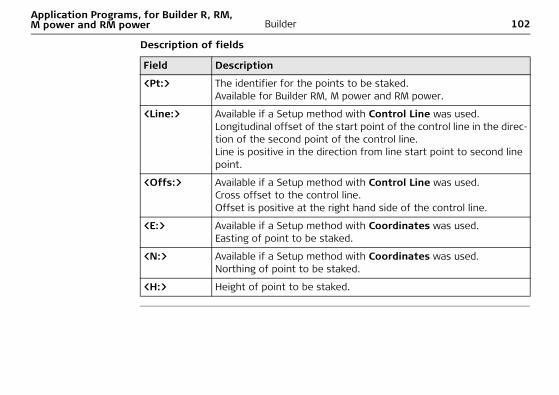
Description of fields
Field Description
<Pt:> The identifier for the points to be staked.Available for Builder RM, M power and RM power.
<Line:> Available if a Setup method with Control Line was used.Longitudinal offset of the start point of the control line in the direc-tion of the second point of the control line.Line is positive in the direction from line start point to second line point.
<Offs:> Available if a Setup method with Control Line was used.Cross offset to the control line. Offset is positive at the right hand side of the control line.
<E:> Available if a Setup method with Coordinates was used.Easting of point to be staked.
<N:> Available if a Setup method with Coordinates was used.Northing of point to be staked.
<H:> Height of point to be staked.
Application Programs, for Builder R, RM, M power and RM power
Builder 103
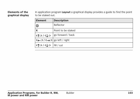
Elements of the graphical display
In application program Layout a graphical display provides a guide to find the point to be staked out.
Element Description
Reflector
X Point to be staked
< :> / < :> go forward / back
< :> / < :> go left / right
< :> / < :> fill / cut
104BuilderApplication Programs, for Builder R, RM, M power and RM power
10.3 As Built
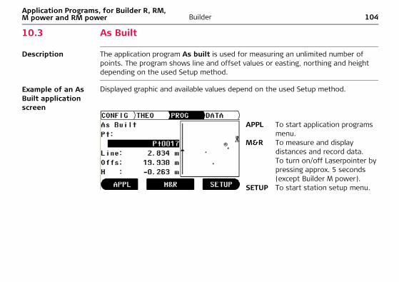
Description The application program As built is used for measuring an unlimited number of points. The program shows line and offset values or easting, northing and height depending on the used Setup method.
Example of an As Built application screen
Displayed graphic and available values depend on the used Setup method.
APPL To start application programs menu.
M&R To measure and display distances and record data.To turn on/off Laserpointer by pressing approx. 5 seconds (except Builder M power).
SETUP To start station setup menu.
Application Programs, for Builder R, RM, M power and RM power
Builder 105
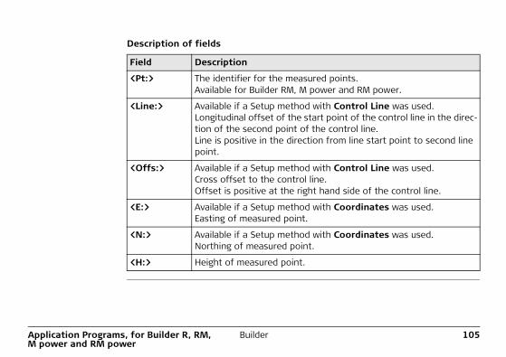
Description of fields
Field Description
<Pt:> The identifier for the measured points.Available for Builder RM, M power and RM power.
<Line:> Available if a Setup method with Control Line was used.Longitudinal offset of the start point of the control line in the direc-tion of the second point of the control line.Line is positive in the direction from line start point to second line point.
<Offs:> Available if a Setup method with Control Line was used.Cross offset to the control line. Offset is positive at the right hand side of the control line.
<E:> Available if a Setup method with Coordinates was used.Easting of measured point.
<N:> Available if a Setup method with Coordinates was used.Northing of measured point.
<H:> Height of measured point.
106BuilderApplication Programs, for Builder R, RM, M power and RM power
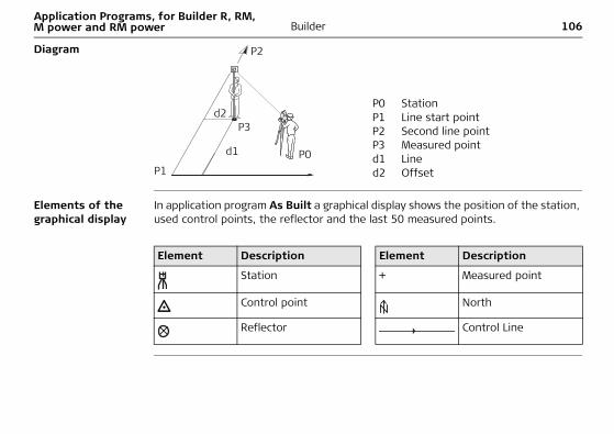
Diagram
Elements of the graphical display
In application program As Built a graphical display shows the position of the station, used control points, the reflector and the last 50 measured points.
P0 StationP1 Line start pointP2 Second line pointP3 Measured pointd1 Lined2 Offset
P2
P1P0
P3
d1
d2
Element Description Element Description
Station + Measured point
Control point North
Reflector Control Line
Application Programs, for Builder R, RM, M power and RM power
Builder 107
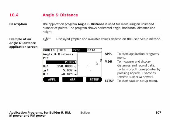
10.4 Angle & Distance
Description The application program Angle & Distance is used for measuring an unlimited number of points. The program shows horizontal angle, horizontal distance and height.
Example of an Angle & Distance application screen
Displayed graphic and available values depend on the used Setup method.
APPL To start application programs menu.
M&R To measure and display distances and record data.To turn on/off Laserpointer by pressing approx. 5 seconds (except Builder M power).
SETUP To start station setup menu.
108BuilderApplication Programs, for Builder R, RM, M power and RM power
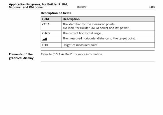
Description of fields
Elements of the graphical display
Refer to "10.3 As Built" for more information.
Field Description
<Pt:> The identifier for the measured points.Available for Builder RM, M power and RM power.
<Hz:> The current horizontal angle.
The measured horizontal distance to the target point.
<H:> Height of measured point.
Application Programs, for Builder R, RM, M power and RM power
Builder 109
10.5 Tie Distance
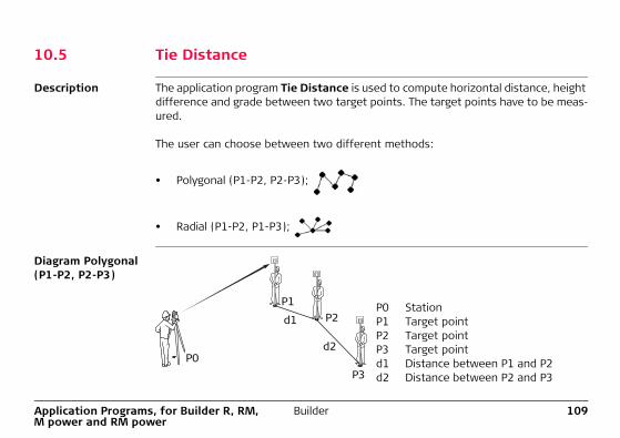
Description The application program Tie Distance is used to compute horizontal distance, height difference and grade between two target points. The target points have to be meas-ured.
The user can choose between two different methods:
• Polygonal (P1-P2, P2-P3);
• Radial (P1-P2, P1-P3);
Diagram Polygonal (P1-P2, P2-P3)
P0 StationP1 Target pointP2 Target pointP3 Target pointd1 Distance between P1 and P2d2 Distance between P2 and P3
P1
d1
d2
P2
P3P0
110BuilderApplication Programs, for Builder R, RM, M power and RM power
Diagram Radial (P1-P2, P1-P3)
Example of a Tie Distance result screen
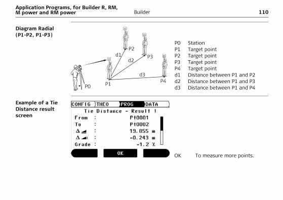
P0 StationP1 Target pointP2 Target pointP3 Target pointP4 Target pointd1 Distance between P1 and P2d2 Distance between P1 and P3d3 Distance between P1 and P4
P1
d1d2
d3
P2P3
P4P0
OK To measure more points.
Application Programs, for Builder R, RM, M power and RM power
Builder 111
Description of fields
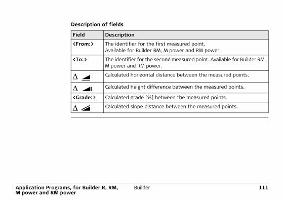
Field Description
<From:> The identifier for the first measured point.Available for Builder RM, M power and RM power.
<To:> The identifier for the second measured point. Available for Builder RM, M power and RM power.
Calculated horizontal distance between the measured points.
Calculated height difference between the measured points.
<Grade:> Calculated grade [%] between the measured points.
Calculated slope distance between the measured points.
112BuilderApplication Programs, for Builder R, RM, M power and RM power
10.6 Area plane (tilt) & Volume
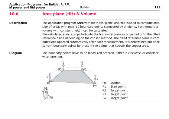
Description The application program Area with methods 'plane' and 'tilt' is used to compute area size of areas with max. 50 boundary points connected by straights. Furthermore a volume with constant height can be calculated.The calculated area is projected onto the horizontal plane or projected onto the tilted reference plane depending on the chosen method. The tilted reference plane is com-puted and updated automatically after each measurement. It is determined out of all current boundary points by those three points that stretch the largest area.
Diagram The boundary points have to be measured ordered, either in clockwise or anticlock-wise direction.
P0 StationP1 Start pointP2 Target pointP3 Target pointP4 Target point
P1
P2 P3
P4
P0
Application Programs, for Builder R, RM, M power and RM power
Builder 113
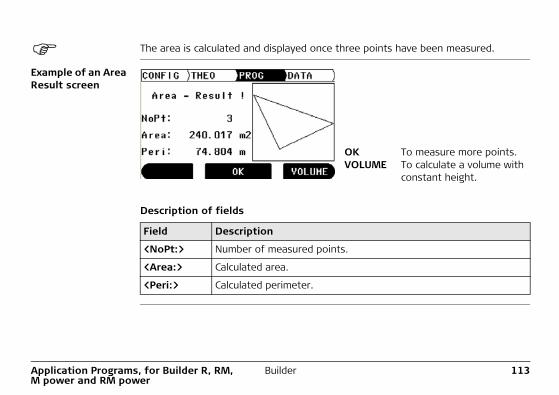
The area is calculated and displayed once three points have been measured.
Example of an Area Result screen
Description of fields
OK To measure more points.VOLUME To calculate a volume with
constant height.
Field Description
<NoPt:> Number of measured points.
<Area:> Calculated area.
<Peri:> Calculated perimeter.
114BuilderApplication Programs, for Builder R, RM, M power and RM power
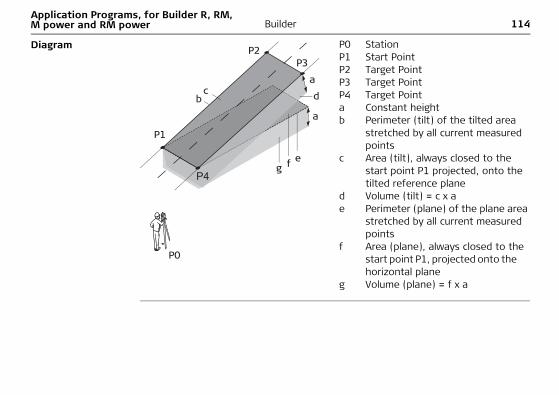
Diagram P0 StationP1 Start PointP2 Target PointP3 Target PointP4 Target Pointa Constant heightb Perimeter (tilt) of the tilted area
stretched by all current measured points
c Area (tilt), always closed to the start point P1 projected, onto the tilted reference plane
d Volume (tilt) = c x ae Perimeter (plane) of the plane area
stretched by all current measured points
f Area (plane), always closed to the start point P1, projected onto the horizontal plane
g Volume (plane) = f x a
P1
a
a
P2P3
P4
P0
c db
f eg
Application Programs, for Builder R, RM, M power and RM power
Builder 115
10.7 Hidden Point (optional)
Description The application program Hidden Point allows measurements to a point that is not directly visible. The point can be determined by a rod or by entering the shift in the line of sight and the side shift.
The user can choose between two different methods:
• Rod
• Shift
The application program Hidden Point is only available for the Builder RM, M power and RM power. The program can be started in total 40 times for trial. Afterwards you have to enter the license code.
116BuilderApplication Programs, for Builder R, RM, M power and RM power
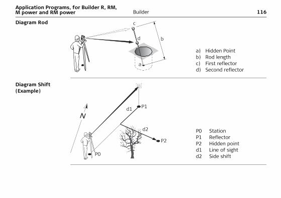
Diagram Rod
Diagram Shift(Example)
a) Hidden Pointb) Rod lengthc) First reflectord) Second reflector
a
b
c
d
P0 StationP1 ReflectorP2 Hidden pointd1 Line of sightd2 Side shift
d1
d2
P0
P1
P2
Application Programs, for Builder R, RM, M power and RM power
Builder 117
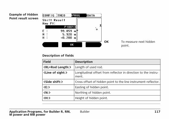
Example of Hidden Point result screen
Description of fields
OK To measure next hidden point.
Field Description
<RL=Rod Length:> Length of used rod.
<Line of sight:> Longitudinal offset from reflector in direction to the instru-ment.
<Side shift:> Cross offset of hidden point to the line instrument-reflector.
<E:> Easting of hidden point.
<N:> Northing of hidden point.
<H:> Height of hidden point.
118BuilderApplication Programs, for Builder R, RM, M power and RM power
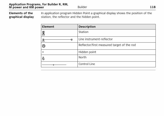
Elements of the graphical display
In application program Hidden Point a graphical display shows the position of the station, the reflector and the hidden point.
Element Description
Station
Line instrument-reflector
Reflector/first measured target of the rod
+ Hidden point
North
Control Line
Application Programs, for Builder R, RM, M power and RM power
Builder 119
10.8 COGO (optional)
Description The application program COGO is an application program to perform coordinate ge-ometry calculations such as:• Coordinates of points• Directions between points• Distances between points
The COGO calculation methods are:• Intersections• Line Extension• Offset Line&Plane• Traverse and Inverse
The application program COGO is only available for the Builder RM, M power and RM power. The program can be started in total 40 times for trial. Afterwards you have to enter the license code.
120BuilderApplication Programs, for Builder R, RM, M power and RM power
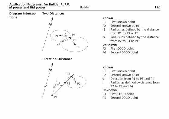
Diagram Intersec-tions
Two Distances
Direction&Distance
KnownP1 First known pointP2 Second known pointr1 Radius, as defined by the distance
from P1 to P3 or P4r2 Radius, as defined by the distance
from P2 to P3 or P4UnknownP3 First COGO pointP4 Second COGO point
KnownP1 First known pointP2 Second known pointα Direction from P1 to P3 and P4r Radius, as defined by distance from
P2 to P3 and P4UnknownP3 First COGO pointP4 Second COGO point
r1
r2P1
P2P3
P4
r
P1
P2
P4
P3
Application Programs, for Builder R, RM, M power and RM power
Builder 121
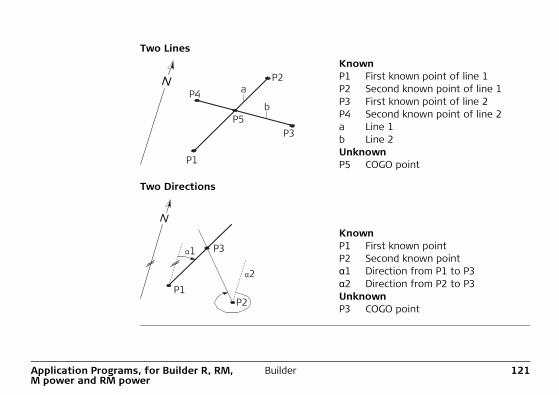
Two Lines
Two Directions
KnownP1 First known point of line 1P2 Second known point of line 1P3 First known point of line 2P4 Second known point of line 2a Line 1b Line 2UnknownP5 COGO point
KnownP1 First known pointP2 Second known pointα1 Direction from P1 to P3α2 Direction from P2 to P3UnknownP3 COGO point
a
b
P1
P2
P3
P4
P5
P1P2
P31
2
122BuilderApplication Programs, for Builder R, RM, M power and RM power
Diagram Line Extension
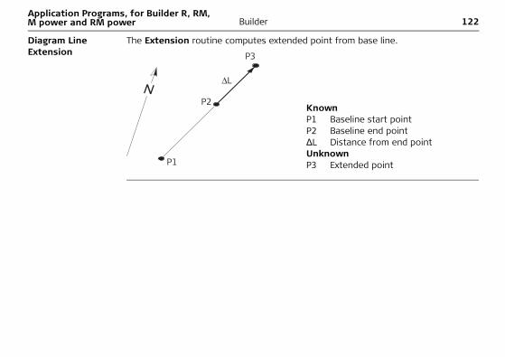
The Extension routine computes extended point from base line.
KnownP1 Baseline start pointP2 Baseline end pointΔL Distance from end pointUnknownP3 Extended pointP1
P2
P3
Application Programs, for Builder R, RM, M power and RM power
Builder 123
Diagram Offset Line & Plane
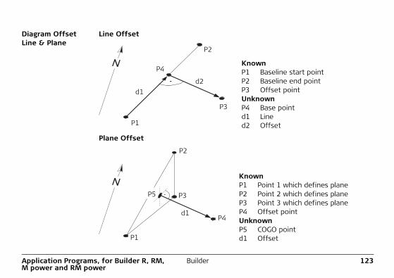
Line Offset
Plane Offset
KnownP1 Baseline start pointP2 Baseline end pointP3 Offset pointUnknownP4 Base pointd1 Lined2 Offset
KnownP1 Point 1 which defines plane P2 Point 2 which defines planeP3 Point 3 which defines planeP4 Offset pointUnknownP5 COGO pointd1 Offset
d1d2
P1
P2
P3
P4
d1
P1
P3
P2
P4
P5
124BuilderApplication Programs, for Builder R, RM, M power and RM power
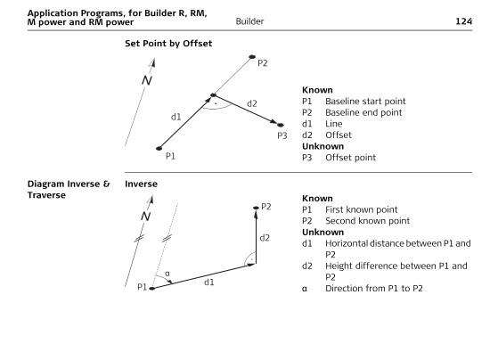
Set Point by Offset
Diagram Inverse & Traverse
Inverse
KnownP1 Baseline start point P2 Baseline end pointd1 Lined2 OffsetUnknownP3 Offset point
d1d2
P1
P2
P3
KnownP1 First known pointP2 Second known pointUnknownd1 Horizontal distance between P1 and
P2d2 Height difference between P1 and
P2α Direction from P1 to P2
d2
d1P1
P2
Application Programs, for Builder R, RM, M power and RM power
Builder 125
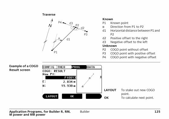
Traverse
Example of a COGO Result screen
KnownP1 Known pointα Direction from P1 to P2d1 Horizontal distance between P1 and
P2d2 Positive offset to the rightd3 Negative offset to the leftUnknownP2 COGO point without offsetP3 COGO point with positive offsetP4 COGO point with negative offset
d1
d2d3
P1
P3
P2P4
LAYOUT To stake out new COGO point.
OK To calculate next point.
126BuilderApplication Programs, for Builder R, RM, M power and RM power
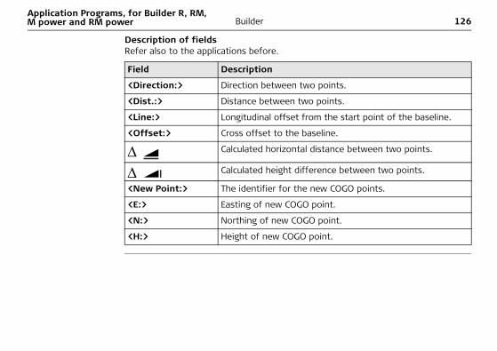
Description of fieldsRefer also to the applications before.
Field Description
<Direction:> Direction between two points.
<Dist.:> Distance between two points.
<Line:> Longitudinal offset from the start point of the baseline.
<Offset:> Cross offset to the baseline.
Calculated horizontal distance between two points.
Calculated height difference between two points.
<New Point:> The identifier for the new COGO points.
<E:> Easting of new COGO point.
<N:> Northing of new COGO point.
<H:> Height of new COGO point.
Application Programs, for Builder R, RM, M power and RM power
Builder 127
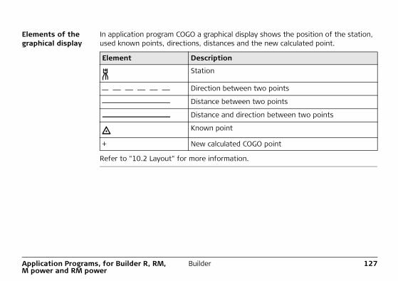
Elements of the graphical display
In application program COGO a graphical display shows the position of the station, used known points, directions, distances and the new calculated point.
Refer to "10.2 Layout" for more information.
Element Description
Station
Direction between two points
Distance between two points
Distance and direction between two points
Known point
+ New calculated COGO point
128BuilderApplication Programs, for Builder R, RM, M power and RM power
10.9 Layout Line/Arc/Spiral (optional)
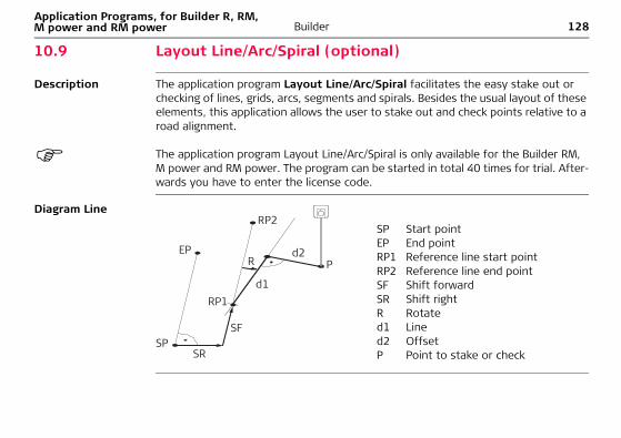
Description The application program Layout Line/Arc/Spiral facilitates the easy stake out or checking of lines, grids, arcs, segments and spirals. Besides the usual layout of these elements, this application allows the user to stake out and check points relative to a road alignment.
The application program Layout Line/Arc/Spiral is only available for the Builder RM, M power and RM power. The program can be started in total 40 times for trial. After-wards you have to enter the license code.
Diagram Line
SP Start pointEP End pointRP1 Reference line start pointRP2 Reference line end pointSF Shift forwardSR Shift rightR Rotated1 Lined2 OffsetP Point to stake or check
SP
EP
RP1d1
Pd2
RP2
R
SF
SR
Application Programs, for Builder R, RM, M power and RM power
Builder 129
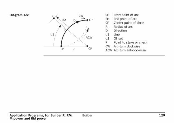
Diagram Arc SP Start point of arcEP End point of arcCP Center point of circleR Radius of arcD Directiond1 Lined2 Offset P Point to stake or checkCW Arc-turn clockwiseACW Arc-turn anticlockwiseCPSP R
d1
d2 EPP
DCW
ACW
130BuilderApplication Programs, for Builder R, RM, M power and RM power
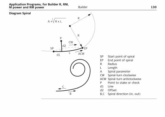
Diagram Spiral
SP Start point of spiralEP End point of spiralR RadiusL LengthA Spiral parameterCW Spiral-turn clockwiseACW Spiral-turn anticlockwiseP Point to stake or checkd1 Lined2 OffsetB,C Spiral direction (in, out)B
C
R
R
L ACW
CW
SP EP
P
d1
d2
A = R x L
Application Programs, for Builder R, RM, M power and RM power
Builder 131
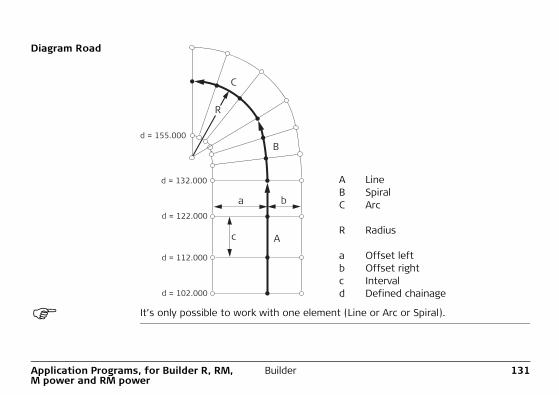
Diagram Road
It’s only possible to work with one element (Line or Arc or Spiral).
A LineB SpiralC Arc
R Radius
a Offset leftb Offset rightc Intervald Defined chainage
A
B
C
a
c
b
R
d = 112.000
d = 122.000
d = 132.000
d = 155.000
d = 102.000
132BuilderApplication Programs, for Builder R, RM, M power and RM power
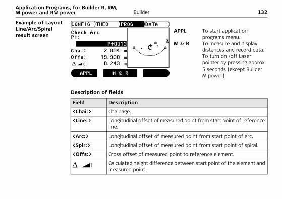
Example of Layout Line/Arc/Spiral result screen
Description of fields
APPL To start application programs menu.
M & R To measure and display distances and record data. To turn on /off Laser pointer by pressing approx. 5 seconds (except Builder M power).
Field Description
<Chai:> Chainage.
<Line:> Longitudinal offset of measured point from start point of reference line.
<Arc:> Longitudinal offset of measured point from start point of arc.
<Spir:> Longitudinal offset of measured point from start point of spiral.
<Offs:> Cross offset of measured point to reference element.
Calculated height difference between start point of the element and measured point.
Application Programs, for Builder R, RM, M power and RM power
Builder 133
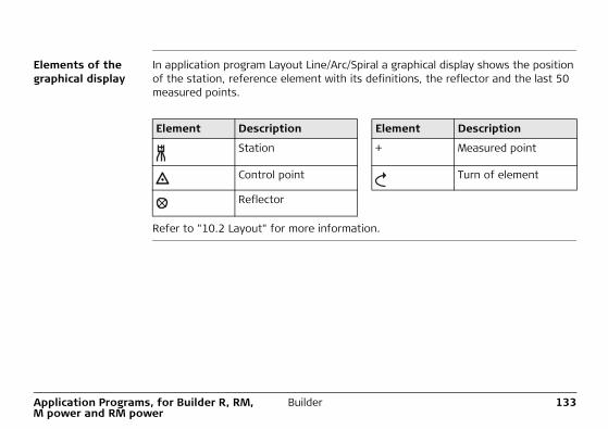
Elements of the graphical display
In application program Layout Line/Arc/Spiral a graphical display shows the position of the station, reference element with its definitions, the reflector and the last 50 measured points.
Refer to "10.2 Layout" for more information.
Element Description Element Description
Station + Measured point
Control point Turn of element
Reflector
134BuilderApplication Programs, for Builder R, RM, M power and RM power
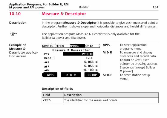
10.10 Measure & Descriptor
Description In the program Measure & Descriptor it is possible to give each measured point a descriptor. Further it shows slope and horizontal distances and height differences.
The application program Measure & Descriptor is only available for the Builder M power and RM power.
Example of Measure & Descriptor applica-tion screen
Description of fields
APPL To start application programs menu.
M & R To measure and display distances and record data. To turn on /off Laser pointer by pressing approx. 5 seconds (except Builder M power).
SETUP To start station setup menu.
Field Description
<Pt:> The identifier for the measured points.
Application Programs, for Builder R, RM, M power and RM power
Builder 135
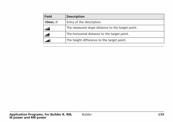
<Desc.:> Entry of the description.
The measured slope distance to the target point.
The horizontal distance to the target point.
The height difference to the target point.
Field Description
136BuilderData Management Mode, for Builder RM, M power and RM power
11 Data Management Mode, for Builder RM, M power and RM power
11.1 Overview
Description The DATA mode is used for:• creating, viewing and deleting data in the field• setting the communication parameters
Descriptions apply to Builder RM, M power and RM power.
Data Management Mode, for Builder RM, M power and RM power
Builder 137
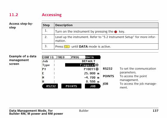
11.2 Accessing
Access step-by-step
Example of a data management screen
Step Description
1. Turn on the instrument by pressing the key.
2. Level up the instrument. Refer to "5.2 Instrument Setup" for more infor-mation.
3. Press until DATA mode is active.
RS232 To set the communication parameters.
POINTS To access the point management.
JOB To access the job manage-ment.
138BuilderData Management Mode, for Builder RM, M power and RM power
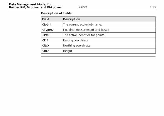
Description of fields
Field Description
<Job:> The current active job name.
<Type:> Fixpoint, Measurement and Result
<Pt:> The active identifier for points.
<E:> Easting coordinate
<N:> Northing coordinate
<H:> Height
Data Management Mode, for Builder RM, M power and RM power
Builder 139
11.3 Jobs
Description Jobs are a summary of different types of data e.g. fixpoints, measurements, result, etc. The job definition consists of the input of job name, operator and remark. Addi-tionally, the system generates time and date at the time of creation.
Active job The active job is the one in which data is stored to. One job is always considered the active job.
Default job A job called Default is always available on the instrument. The job Default is active until a user defined job is created and selected.
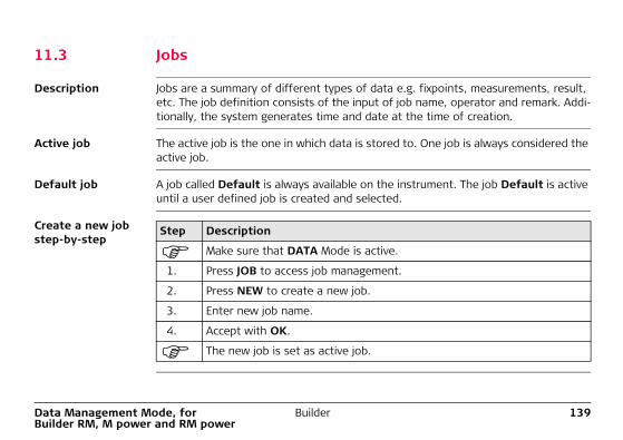
Create a new job step-by-step
Step Description
Make sure that DATA Mode is active.
1. Press JOB to access job management.
2. Press NEW to create a new job.
3. Enter new job name.
4. Accept with OK.
The new job is set as active job.
140BuilderData Management Mode, for Builder RM, M power and RM power
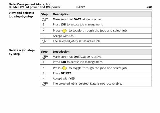
View and select a job step-by-step
Delete a job step-by-step
Step Description
Make sure that DATA Mode is active.
1. Press JOB to access job management.
2. Press to toggle through the jobs and select job.
3. Accept with OK.
The selected job is set as active job.
Step Description
Make sure that DATA Mode is active.
1. Press JOB to access job management.
2. Press to toggle through the jobs and select job.
3. Press DELETE.
4. Accept with YES.
The selected job is deleted. Data is not recoverable.
Data Management Mode, for Builder RM, M power and RM power
Builder 141
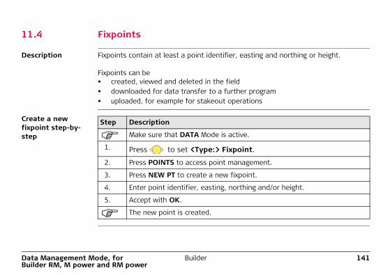
11.4 Fixpoints
Description Fixpoints contain at least a point identifier, easting and northing or height.
Fixpoints can be • created, viewed and deleted in the field• downloaded for data transfer to a further program• uploaded, for example for stakeout operations
Create a new fixpoint step-by-step
Step Description
Make sure that DATA Mode is active.
1. Press to set <Type:> Fixpoint.
2. Press POINTS to access point management.
3. Press NEW PT to create a new fixpoint.
4. Enter point identifier, easting, northing and/or height.
5. Accept with OK.
The new point is created.
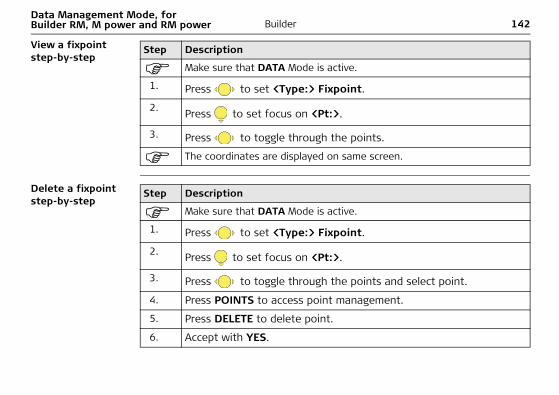
142BuilderData Management Mode, for Builder RM, M power and RM power
View a fixpoint step-by-step
Delete a fixpoint step-by-step
Step Description
Make sure that DATA Mode is active.
1. Press to set <Type:> Fixpoint.
2. Press to set focus on <Pt:>.
3. Press to toggle through the points.
The coordinates are displayed on same screen.
Step Description
Make sure that DATA Mode is active.
1. Press to set <Type:> Fixpoint.
2. Press to set focus on <Pt:>.
3. Press to toggle through the points and select point.
4. Press POINTS to access point management.
5. Press DELETE to delete point.
6. Accept with YES.
Data Management Mode, for Builder RM, M power and RM power
Builder 143
The selected point is deleted. Data is not recoverable.
Step Description
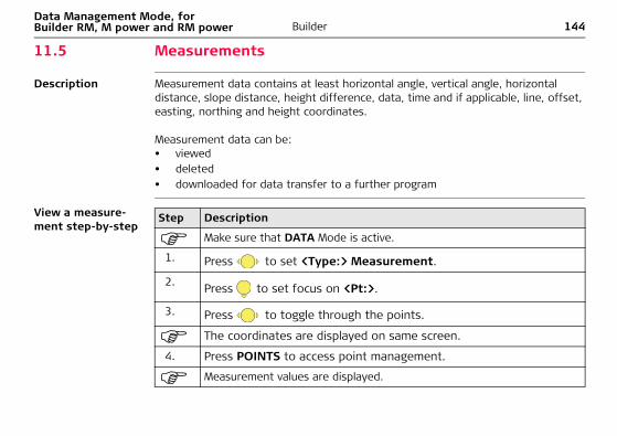
144BuilderData Management Mode, for Builder RM, M power and RM power
11.5 Measurements
Description Measurement data contains at least horizontal angle, vertical angle, horizontal distance, slope distance, height difference, data, time and if applicable, line, offset, easting, northing and height coordinates.
Measurement data can be:• viewed• deleted• downloaded for data transfer to a further program
View a measure-ment step-by-step
Step Description
Make sure that DATA Mode is active.
1. Press to set <Type:> Measurement.
2. Press to set focus on <Pt:>.
3. Press to toggle through the points.
The coordinates are displayed on same screen.
4. Press POINTS to access point management.
Measurement values are displayed.
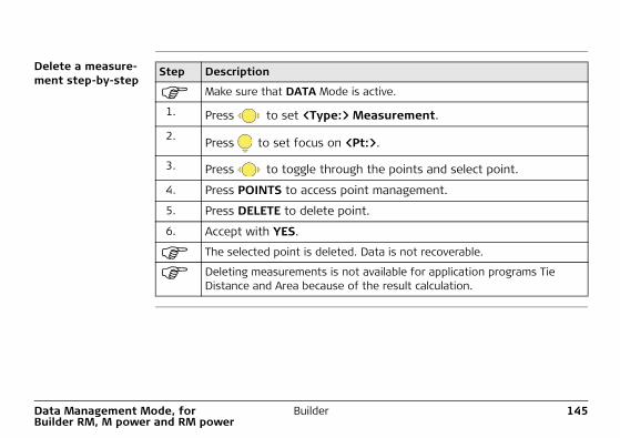
Data Management Mode, for Builder RM, M power and RM power
Builder 145
Delete a measure-ment step-by-step
Step Description
Make sure that DATA Mode is active.
1. Press to set <Type:> Measurement.
2. Press to set focus on <Pt:>.
3. Press to toggle through the points and select point.
4. Press POINTS to access point management.
5. Press DELETE to delete point.
6. Accept with YES.
The selected point is deleted. Data is not recoverable.
Deleting measurements is not available for application programs Tie Distance and Area because of the result calculation.
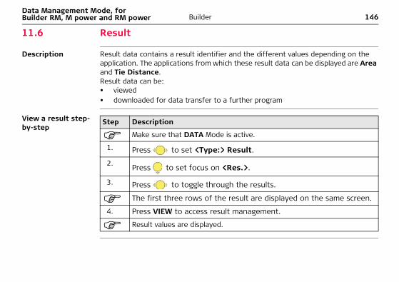
146BuilderData Management Mode, for Builder RM, M power and RM power
11.6 Result
Description Result data contains a result identifier and the different values depending on the application. The applications from which these result data can be displayed are Area and Tie Distance.Result data can be:• viewed• downloaded for data transfer to a further program
View a result step-by-step
Step Description
Make sure that DATA Mode is active.
1. Press to set <Type:> Result.
2. Press to set focus on <Res.>.
3. Press to toggle through the results.
The first three rows of the result are displayed on the same screen.
4. Press VIEW to access result management.
Result values are displayed.
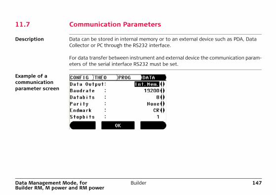
Data Management Mode, for Builder RM, M power and RM power
Builder 147
11.7 Communication Parameters
Description Data can be stored in internal memory or to an external device such as PDA, Data Collector or PC through the RS232 interface.
For data transfer between instrument and external device the communication param-eters of the serial interface RS232 must be set.
Example of a communication parameter screen
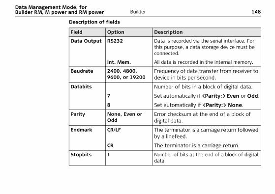
148BuilderData Management Mode, for Builder RM, M power and RM power
Description of fields
Field Option Description
Data Output RS232 Data is recorded via the serial interface. For this purpose, a data storage device must be connected.
Int. Mem. All data is recorded in the internal memory.
Baudrate 2400, 4800, 9600, or 19200
Frequency of data transfer from receiver to device in bits per second.
Databits Number of bits in a block of digital data.
7 Set automatically if <Parity:> Even or Odd.
8 Set automatically if <Parity:> None.
Parity None, Even or Odd
Error checksum at the end of a block of digital data.
Endmark CR/LF The terminator is a carriage return followed by a linefeed.
CR The terminator is a carriage return.
Stopbits 1 Number of bits at the end of a block of digital data.
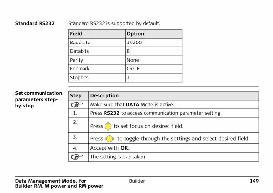
Data Management Mode, for Builder RM, M power and RM power
Builder 149
Standard RS232 Standard RS232 is supported by default.
Set communication parameters step-by-step
Field Option
Baudrate 19200
Databits 8
Parity None
Endmark CR/LF
Stopbits 1
Step Description
Make sure that DATA Mode is active.
1. Press RS232 to access communication parameter setting.
2.Press to set focus on desired field.
3. Press to toggle through the settings and select desired field.
4. Accept with OK.
The setting is overtaken.
150BuilderData Management Mode, for Builder RM, M power and RM power
11.8 Data Transfer
Description For data transfer use:• Construction Data Manager
Simple office software which supports the exchange of Leica TPS data with the PC, using a Windows® application.
OR• Leica Geo Office Tools
Office software including a series of programs which supports working with the Builder RM, M power and RM power.
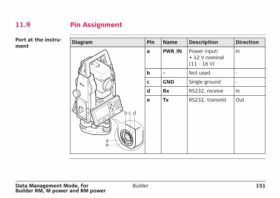
Data Management Mode, for Builder RM, M power and RM power
Builder 151
11.9 Pin Assignment
Port at the instru-ment
Diagram Pin Name Description Direction
a PWR_IN Power input: + 12 V nominal(11 - 16 V)
In
b - Not used -
c GND Single ground -
d Rx RS232, receive In
e Tx RS232, transmit Out
b c d
ae
152BuilderEDM Settings
12 EDM Settings12.1 EDM
Description With the instrument different settings are available for measurements with red dot (without reflectors) and fine/fast (with reflectors). The LED on the keyboard indi-cates the selected type. Depending on the selected type the selection of prism types is different. Red dot contains the flat prism as the only one and isn't displayed.Beside the settings of the EDM it is possible to set the reflector height.
Descriptions apply only to Builder M power and RM power.
Access step-by-step
Step Description
1. Turn on the instrument by pressing the key.
2. Press the key.
EDM settings are not accessible during the following: • CONFIG Mode: Choice list is opened.• THEO Mode: Level or orientation procedure is running.• PROG Mode: „YES or NO“ decision, for example „Station and Orienta-
tion will be changed and set“ or Point List Search is running.• DATA Mode: One of the procedures RS232, POINTS or JOB is running.
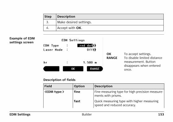
EDM Settings Builder 153
Example of EDM settings screen
Description of fields
3. Make desired settings.
4. Accept with OK.
Step Description
OK To accept settings.RANGE To disable limited distance
measurement. Button disappears when entered once.
Field Option Description
<EDM type:> fine Fine measuring type for high precision measure-ments with prisms.
fast Quick measuring type with higher measuring speed and reduced accuracy.
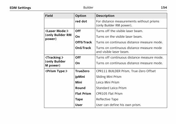
154BuilderEDM Settings
red dot For distance measurements without prisms (only Builder RM power).
<Laser Mode:>(only Builder RM power)
Off Turns off the visible laser beam.
On Turns on the visible laser beam.
Off&Track Turns on continuous distance measure mode.
On&Track Turns on continuous distance measure mode and visible laser beam.
<Tracking:>(only Builder M power)
Off Turns off continuous distance measure mode.
On Turns on continuous distance measure mode.
<Prism Type:> TrueZero CPR111 BUILDER Prism, True-Zero Offset
JpMini Sliding Mini Prism
Mini Leica Mini Prism
Round Standard Leica Prism
Flat Prism CPR105 Flat Prism
Tape Reflective Tape
User User can define his own prism.
Field Option Description
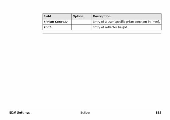
EDM Settings Builder 155
<Prism Const.:> Entry of a user specific prism constant in [mm].
<hr:> Entry of reflector height.
Field Option Description
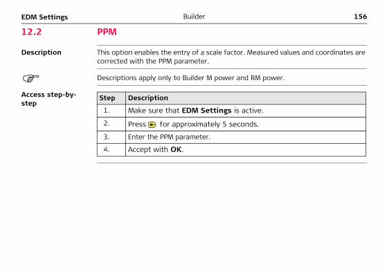
156BuilderEDM Settings
12.2 PPM
Description This option enables the entry of a scale factor. Measured values and coordinates are corrected with the PPM parameter.
Descriptions apply only to Builder M power and RM power.
Access step-by-step
Step Description
1. Make sure that EDM Settings is active.
2. Press for approximately 5 seconds.
3. Enter the PPM parameter.
4. Accept with OK.
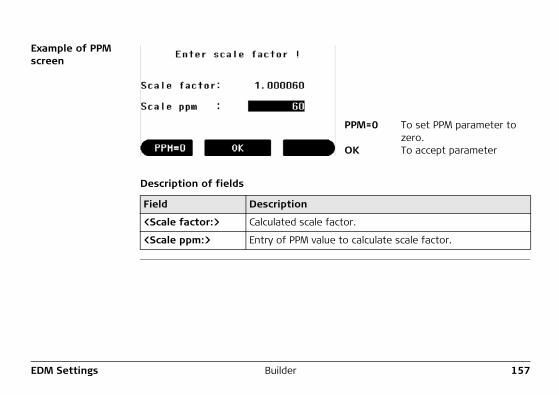
EDM Settings Builder 157
Example of PPM screen
Description of fields
PPM=0 To set PPM parameter to zero.
OK To accept parameter
Field Description
<Scale factor:> Calculated scale factor.
<Scale ppm:> Entry of PPM value to calculate scale factor.
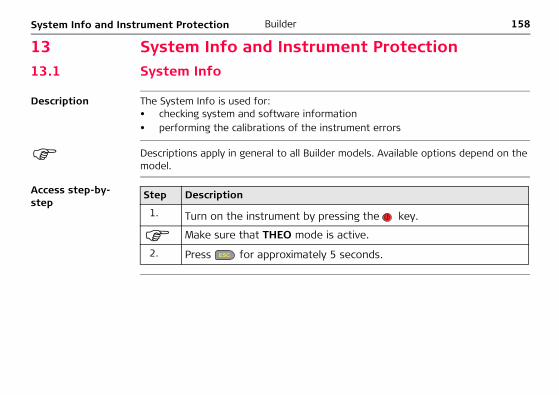
158BuilderSystem Info and Instrument Protection
13 System Info and Instrument Protection13.1 System Info
Description The System Info is used for:• checking system and software information• performing the calibrations of the instrument errors
Descriptions apply in general to all Builder models. Available options depend on the model.
Access step-by-step
Step Description
1. Turn on the instrument by pressing the key.
Make sure that THEO mode is active.
2. Press for approximately 5 seconds.
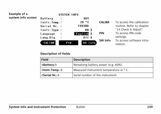
System Info and Instrument Protection Builder 159
Example of a system info screen
Description of fields
CALIBR To access the calibration routine. Refer to chapter "14 Check & Adjust".
PIN To access PIN-code settings.
SW Info To access software infor-mation.
Field Description
<Battery:> Remaining battery power (e.g. 60%).
<Instr.Temp.:> Measured instrument temperature in ° C.
<Serial Nr.:> Serial number of the instrument.
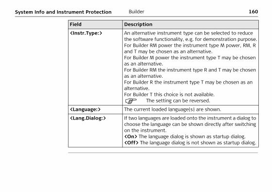
160BuilderSystem Info and Instrument Protection
<Instr.Type:> An alternative instrument type can be selected to reduce the software functionality, e.g. for demonstration purpose.For Builder RM power the instrument type M power, RM, R and T may be chosen as an alternative.For Builder M power the instrument type T may be chosen as an alternative.For Builder RM the instrument type R and T may be chosen as an alternative.For Builder R the instrument type T may be chosen as an alternative.For Builder T this choice is not available.
The setting can be reversed.
<Language:> The current loaded language(s) are shown.
<Lang.Dialog:> If two languages are loaded onto the instrument a dialog to choose the language can be shown directly after switching on the instrument.<On> The language dialog is shown as startup dialog.<Off> The language dialog is not shown as startup dialog.
Field Description
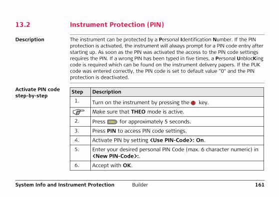
System Info and Instrument Protection Builder 161
13.2 Instrument Protection (PIN)
Description The instrument can be protected by a Personal Identification Number. If the PIN protection is activated, the instrument will always prompt for a PIN code entry after starting up. As soon as the PIN was activated the access to the PIN code settings requires the PIN. If a wrong PIN has been typed in five times, a Personal UnblocKing code is required which can be found on the instrument delivery papers. If the PUK code was entered correctly, the PIN code is set to default value "0" and the PIN protection is deactivated.
Activate PIN code step-by-step
Step Description
1. Turn on the instrument by pressing the key.
Make sure that THEO mode is active.
2. Press for approximately 5 seconds.
3. Press PIN to access PIN code settings.
4. Activate PIN by setting <Use PIN-Code>: On.
5. Enter your desired personal PIN Code (max. 6 character numeric) in <New PIN-Code>:.
6. Accept with OK.
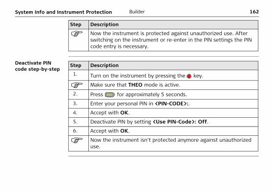
162BuilderSystem Info and Instrument Protection
Deactivate PIN code step-by-step
Now the instrument is protected against unauthorized use. After switching on the instrument or re-enter in the PIN settings the PIN code entry is necessary.
Step Description
Step Description
1. Turn on the instrument by pressing the key.
Make sure that THEO mode is active.
2. Press for approximately 5 seconds.
3. Enter your personal PIN in <PIN-CODE>:.
4. Accept with OK.
5. Deactivate PIN by setting <Use PIN-Code>: Off.
6. Accept with OK.
Now the instrument isn‘t protected anymore against unauthorized use.
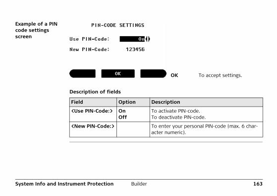
System Info and Instrument Protection Builder 163
Example of a PIN code settings screen
Description of fields
OK To accept settings.
Field Option Description
<Use PIN-Code:> OnOff
To activate PIN-code.To deactivate PIN-code.
<New PIN-Code:> To enter your personal PIN-code (max. 6 char-acter numeric).
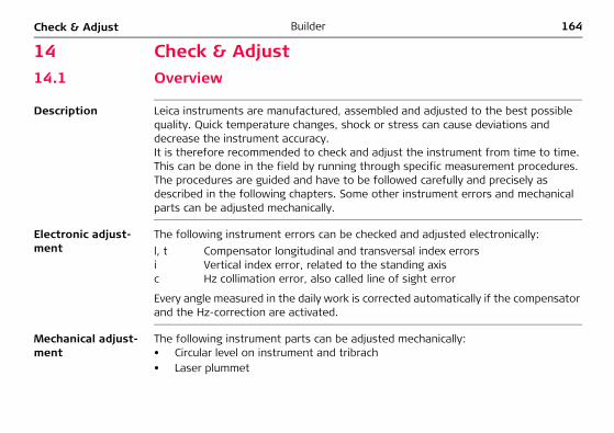
164BuilderCheck & Adjust
14 Check & Adjust14.1 Overview
Description Leica instruments are manufactured, assembled and adjusted to the best possible quality. Quick temperature changes, shock or stress can cause deviations and decrease the instrument accuracy.It is therefore recommended to check and adjust the instrument from time to time. This can be done in the field by running through specific measurement procedures. The procedures are guided and have to be followed carefully and precisely as described in the following chapters. Some other instrument errors and mechanical parts can be adjusted mechanically.
Electronic adjust-ment
The following instrument errors can be checked and adjusted electronically:
Every angle measured in the daily work is corrected automatically if the compensator and the Hz-correction are activated.
Mechanical adjust-ment
The following instrument parts can be adjusted mechanically:• Circular level on instrument and tribrach• Laser plummet
l, t Compensator longitudinal and transversal index errorsi Vertical index error, related to the standing axisc Hz collimation error, also called line of sight error
Check & Adjust Builder 165
• Screws on tripod• Visible red laser beam for Builder R, RM and RM power. Only Leica Geosystems
authorized service workshops are entitled to adjust these products.• Vertical line of the reticule for Builder T
During the manufacturing process, the instrument errors are carefully determined and set to zero. As mentioned above, these errors can change and it is highly recom-mended to redetermine them in the following situations:• Before the first use• Before every high precision survey• After rough or long transportations• After long working periods• After long storage periods• If the temperature difference between current environment and the temperature
at the last calibration is more than 20°C
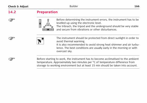
166BuilderCheck & Adjust
14.2 Preparation
Before starting to work, the instrument has to become acclimatised to the ambient temperature. Approximately two minutes per °C of temperature difference from storage to working environment but at least 15 min should be taken into account.
Before determining the instrument errors, the instrument has to be levelled-up using the electronic level. The tribrach, the tripod and the underground should be very stable and secure from vibrations or other disturbances.
The instrument should be protected from direct sunlight in order to avoid thermal warming.It is also recommended to avoid strong heat shimmer and air turbu-lence. The best conditions are usually early in the morning or with overcast sky.
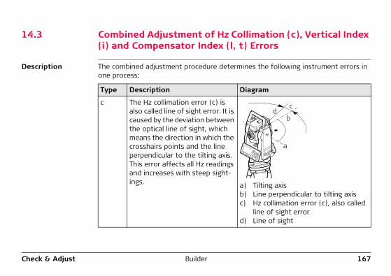
Check & Adjust Builder 167
14.3 Combined Adjustment of Hz Collimation (c), Vertical Index (i) and Compensator Index (l, t) Errors
Description The combined adjustment procedure determines the following instrument errors in one process:
Type Description Diagram
c The Hz collimation error (c) is also called line of sight error. It is caused by the deviation between the optical line of sight, which means the direction in which the crosshairs points and the line perpendicular to the tilting axis. This error affects all Hz readings and increases with steep sight-ings. a) Tilting axis
b) Line perpendicular to tilting axisc) Hz collimation error (c), also called
line of sight errord) Line of sight
a
bd
c
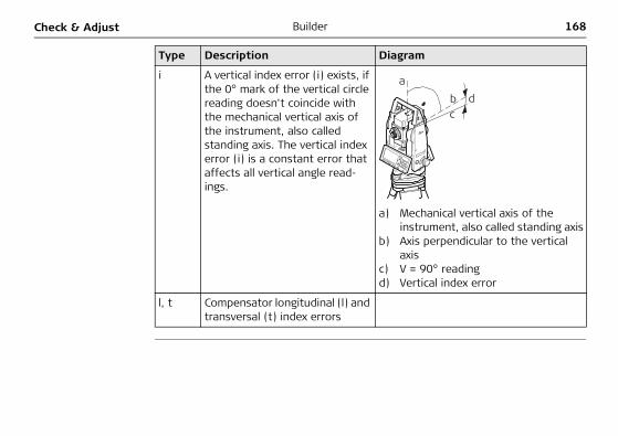
168BuilderCheck & Adjust
i A vertical index error (i) exists, if the 0° mark of the vertical circle reading doesn't coincide with the mechanical vertical axis of the instrument, also called standing axis. The vertical index error (i) is a constant error that affects all vertical angle read-ings.
a) Mechanical vertical axis of the instrument, also called standing axis
b) Axis perpendicular to the vertical axis
c) V = 90° readingd) Vertical index error
l, t Compensator longitudinal (l) and transversal (t) index errors
Type Description Diagram
bc
da
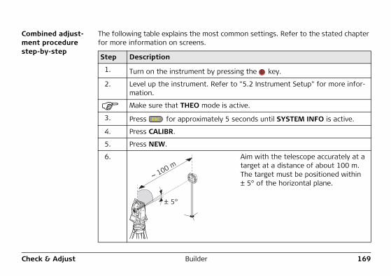
Check & Adjust Builder 169
Combined adjust-ment procedure step-by-step
The following table explains the most common settings. Refer to the stated chapter for more information on screens.
Step Description
1. Turn on the instrument by pressing the key.
2. Level up the instrument. Refer to "5.2 Instrument Setup" for more infor-mation.
Make sure that THEO mode is active.
3. Press for approximately 5 seconds until SYSTEM INFO is active.
4. Press CALIBR.
5. Press NEW.
6. Aim with the telescope accurately at a target at a distance of about 100 m. The target must be positioned within ± 5° of the horizontal plane.
± 5°
~ 100 m
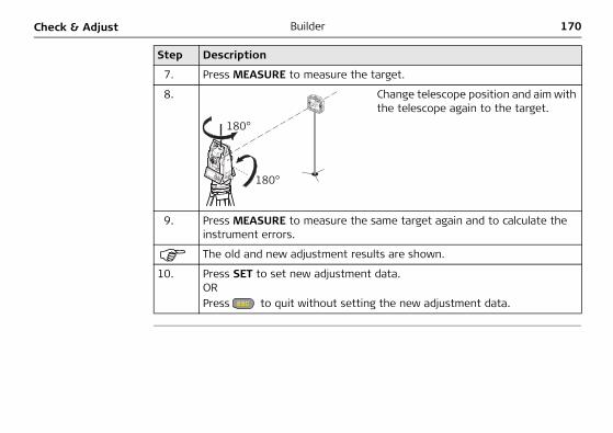
170BuilderCheck & Adjust
7. Press MEASURE to measure the target.
8. Change telescope position and aim with the telescope again to the target.
9. Press MEASURE to measure the same target again and to calculate the instrument errors.
The old and new adjustment results are shown.
10. Press SET to set new adjustment data.ORPress to quit without setting the new adjustment data.
Step Description
180°
180°
Check & Adjust Builder 171
Set Hz correction (c)
Field Option Field Description
<Hz-Correction:> On The horizontal angles are corrected for the line of sight and if <Compensator: On> transversal tilt errors.
Off Horizontal angles are not corrected. After switching on the instrument, the setting is automatically reset to <Hz-Correction: On >.
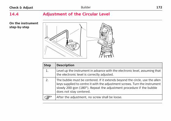
172BuilderCheck & Adjust
14.4 Adjustment of the Circular Level
On the instrument step-by-step
Step Description
1. Level up the instrument in advance with the electronic level, assuming that the electronic level is correctly adjusted.
2. The bubble must be centered. If it extends beyond the circle, use the allen keys supplied to centre it with the adjustment screws. Turn the instrument slowly 200 gon (180°). Repeat the adjustment procedure if the bubble does not stay centered.
After the adjustment, no screw shall be loose.
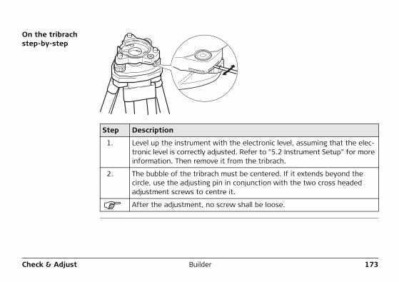
Check & Adjust Builder 173
On the tribrach step-by-step
Step Description
1. Level up the instrument with the electronic level, assuming that the elec-tronic level is correctly adjusted. Refer to "5.2 Instrument Setup" for more information. Then remove it from the tribrach.
2. The bubble of the tribrach must be centered. If it extends beyond the circle, use the adjusting pin in conjunction with the two cross headed adjustment screws to centre it.
After the adjustment, no screw shall be loose.
174BuilderCheck & Adjust
14.5 Adjustment of the Laser Plummet
The laser plummet is located in the vertical axis of the instrument. Under normal conditions of use, the laser plummet does not need adjusting. If an adjustment is necessary due to external influences, the instrument has to be returned to any Leica Geosystems authorized service workshop.
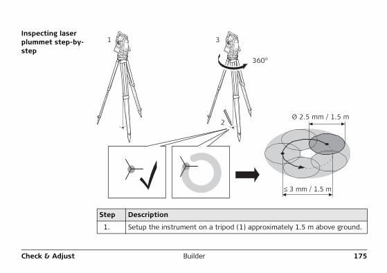
Check & Adjust Builder 175
Inspecting laser plummet step-by-step
Step Description
1. Setup the instrument on a tripod (1) approximately 1.5 m above ground.
1
2
3
360°
≤ 3 mm / 1.5 m
Ø 2.5 mm / 1.5 m
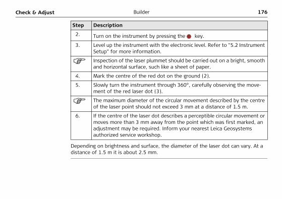
176BuilderCheck & Adjust
Depending on brightness and surface, the diameter of the laser dot can vary. At a distance of 1.5 m it is about 2.5 mm.
2. Turn on the instrument by pressing the key.
3. Level up the instrument with the electronic level. Refer to "5.2 Instrument Setup" for more information.
Inspection of the laser plummet should be carried out on a bright, smooth and horizontal surface, such like a sheet of paper.
4. Mark the centre of the red dot on the ground (2).
5. Slowly turn the instrument through 360°, carefully observing the move-ment of the red laser dot (3).
The maximum diameter of the circular movement described by the centre of the laser point should not exceed 3 mm at a distance of 1.5 m.
6. If the centre of the laser dot describes a perceptible circular movement or moves more than 3 mm away from the point which was first marked, an adjustment may be required. Inform your nearest Leica Geosystems authorized service workshop.
Step Description
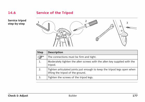
Check & Adjust Builder 177
14.6 Service of the Tripod
Service tripod step-by-step
Step Description
The connections must be firm and tight.
1. Moderately tighten the allen screws with the allen key supplied with the tripod.
2. Tighten articulated joints just enough to keep the tripod legs open when lifting the tripod of the ground.
3. Tighten the screws of the tripod legs.
1 23
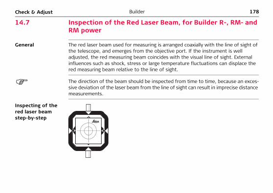
178BuilderCheck & Adjust
14.7 Inspection of the Red Laser Beam, for Builder R-, RM- and RM power
General The red laser beam used for measuring is arranged coaxially with the line of sight of the telescope, and emerges from the objective port. If the instrument is well adjusted, the red measuring beam coincides with the visual line of sight. External influences such as shock, stress or large temperature fluctuations can displace the red measuring beam relative to the line of sight.
The direction of the beam should be inspected from time to time, because an exces-sive deviation of the laser beam from the line of sight can result in imprecise distance measurements.
Inspecting of the red laser beam step-by-step
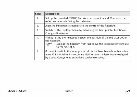
Check & Adjust Builder 179
Step Description
1. Set up the provided CPR105 flatprism between 5 m and 20 m with the reflective tape side facing the instrument.
2. Align the instrument crosshairs to the centre of the flatprism.
3. Switch on the red laser beam by activating the laser pointer function in Configuration Mode.
4. Without using the telescope inspect the position of the red laser dot on the flatprism.
Look at the flatprism from just above the telescope or from just to the side of it.
5. If the dot is within the inner printed circle the laser beam is within toler-ance. If it is outside it is recommended to have the laser beam realigned by a Leica Geosystems authorized service workshop.
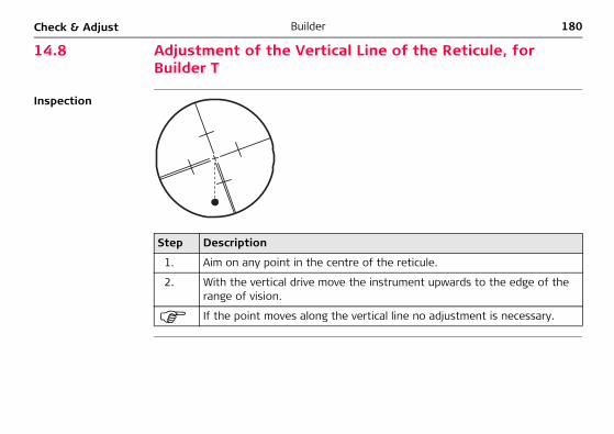
180BuilderCheck & Adjust
14.8 Adjustment of the Vertical Line of the Reticule, for Builder T
Inspection
Step Description
1. Aim on any point in the centre of the reticule.
2. With the vertical drive move the instrument upwards to the edge of the range of vision.
If the point moves along the vertical line no adjustment is necessary.
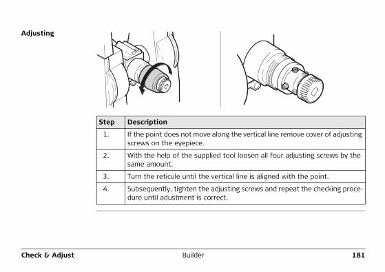
Check & Adjust Builder 181
Adjusting
Step Description
1. If the point does not move along the vertical line remove cover of adjusting screws on the eyepiece.
2. With the help of the supplied tool loosen all four adjusting screws by the same amount.
3. Turn the reticule until the vertical line is aligned with the point.
4. Subsequently, tighten the adjusting screws and repeat the checking proce-dure until adustment is correct.

182BuilderCare and Transport
15 Care and Transport15.1 Transport
Transport in the field
When transporting the equipment in the field, always make sure that you• either carry the product in its original transport container,• or carry the tripod with its legs splayed across your shoulder, keeping the
attached product upright.
Transport in a road vehicle
Never carry the product loose in a road vehicle, as it can be affected by shock and vibration. Always carry the product in its transport container and secure it.
Shipping When transporting the product by rail, air or sea, always use the complete original Leica Geosystems packaging, transport container and cardboard box, or its equiva-lent, to protect against shock and vibration.
Shipping, transport of batteries
When transporting or shipping batteries, the person in charge of the product must ensure that the applicable national and international rules and regulations are observed. Before transportation or shipping, contact your local passenger or freight transport company.
Care and Transport Builder 183
Field adjustment After transport inspect the field adjustment parameters given in this user manual before using the product.If the equipment is to be stored for a long time, remove the alkaline batteries from the product in order to avoid the danger of leakage.
184BuilderCare and Transport
15.2 Storage
Product Respect the temperature limits when storing the equipment, particularly in summer if the equipment is inside a vehicle. Refer to "17 Technical Data" for information about temperature limits.
Field adjustment After long periods of storage inspect the field adjustment parameters given in this user manual before using the product.
NiMH and Alkaline batteries
• Refer to "17.3 General Technical Data of the Instrument" for information about storage temperature range.
• A storage temperature range of 0°C to +20°C / +32°F to +68°F in dry environ-ment is recommended to minimize self-discharging of the battery.
• At the recommended storage temperature range, batteries containing a 10% to 50% charge can be stored for up to one year. After this storage period the batteries must be recharged.
• Remove batteries from the product and the charger before storing.• After storage recharge batteries (NiMH) before using.• Protect batteries from damp and wetness. Wet or damp batteries must be dried
before storing or use.
Care and Transport Builder 185
15.3 Cleaning and Drying
Objective, eyepiece and prisms
• Blow dust off lenses and prisms.• Never touch the glass with your fingers.• Use only a clean, soft, lint-free cloth for cleaning. If necessary, moisten the cloth
with water or pure alcohol. Do not use other liquids; these may attack the polymer components. For cleaning the flat prism pure alcohol is not allowed.
Fogging of prisms Reflector prisms that are cooler than the ambient temperature tend to fog. It is not enough simply to wipe them. Keep them for some time inside your jacket or in the vehicle to allow them to adjust to the ambient temperature.
Damp products Dry the product, the transport container, the foam inserts and the accessories at a temperature not greater than 40°C / 104°F and clean them. Do not repack until everything is completely dry.
Cables and plugs Keep plugs clean and dry. Blow away any dirt lodged in the plugs of the connecting cables.
186BuilderSafety Directions
16 Safety Directions16.1 General
Description The following directions should enable the person responsible for the product, and the person who actually uses the equipment, to anticipate and avoid operational hazards.
The person responsible for the product must ensure that all users understand these directions and adhere to them.
Safety Directions Builder 187
16.2 Intended Use
Permitted use • Measuring horizontal and vertical angles.• Measuring distances.• Recording measurements.• Computing by means of software.• Visualizing the aiming direction and vertical axis.
Adverse use • Use of the product without instruction.• Use outside of the intended limits.• Disabling safety systems.• Removal of hazard notices.• Opening the product using tools, for example screwdriver, unless this is specifi-
cally permitted for certain functions.• Modification or conversion of the product.• Use after misappropriation.• Use of products with obviously recognizable damages or defects.• Use with accessories from other manufacturers without the prior explicit
approval of Leica Geosystems.• Aiming directly into the sun.• Inadequate safeguards at the working site, for example when measuring on
roads.
188BuilderSafety Directions
• Deliberate dazzling of third parties.• Controlling of machines, moving objects or similar monitoring application without
additional control- and safety installations.
�Warning Adverse use can lead to injury, malfunction and damage. It is the task of the person responsible for the equipment to inform the user about hazards and how to counteract them. The product is not to be operated until the user has been instructed on how to work with it.
Safety Directions Builder 189
16.3 Limits of Use
Environment Suitable for use in an atmosphere appropriate for permanent human habitation: not suitable for use in aggressive or explosive environments.
�Danger Local safety authorities and safety experts must be contacted before working in hazardous areas, or in close proximity to electrical installations or similar situations by the person in charge of the product.
190BuilderSafety Directions
16.4 Responsibilities
Manufacturer of the product
Leica Geosystems AG, CH-9435 Heerbrugg, hereinafter referred to as Leica Geosys-tems, is responsible for supplying the product, including the user manual and original accessories, in a completely safe condition.
Manufacturers of nonLeica Geosystems accessories
The manufacturers of non Leica Geosystems accessories for the product are respon-sible for developing, implementing and communicating safety concepts for their products, and are also responsible for the effectiveness of those safety concepts in combination with the Leica Geosystems product.
Person in charge of the product
The person in charge of the product has the following duties:• To understand the safety instructions on the product and the instructions in the
user manual.• To be familiar with local regulations relating to safety and accident prevention.• To inform Leica Geosystems immediately if the product and the application
becomes unsafe.
�Warning The person responsible for the product must ensure that it is used in accordance with the instructions. This person is also accountable for the training and the deployment of personnel who use the product and for the safety of the equipment in use.
Safety Directions Builder 191
16.5 Hazards of Use
�Warning The absence of instruction, or the inadequate imparting of instruction, can lead to incorrect or adverse use, and can give rise to accidents with far-reaching human, material, financial and environmental consequences.Precautions:All users must follow the safety directions given by the manufacturer and the direc-tions of the person responsible for the product.
�Caution Watch out for erroneous measurement results if the product has been dropped or has been misused, modified, stored for long periods or transported.Precautions:Periodically carry out test measurements and perform the field adjustments indicated in the user manual, particularly after the product has been subjected to abnormal use and before and after important measurements.
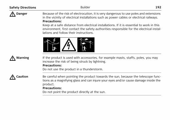
192BuilderSafety Directions
�Danger Because of the risk of electrocution, it is very dangerous to use poles and extensions in the vicinity of electrical installations such as power cables or electrical railways.Precautions:Keep at a safe distance from electrical installations. If it is essential to work in this environment, first contact the safety authorities responsible for the electrical instal-lations and follow their instructions.
�Warning If the product is used with accessories, for example masts, staffs, poles, you may increase the risk of being struck by lightning.Precautions:Do not use the product in a thunderstorm.
�Caution Be careful when pointing the product towards the sun, because the telescope func-tions as a magnifying glass and can injure your eyes and/or cause damage inside the product.Precautions:Do not point the product directly at the sun.
Safety Directions Builder 193
�Warning During dynamic applications, for example stakeout procedures there is a danger of accidents occurring if the user does not pay attention to the environmental condi-tions around, for example obstacles, excavations or traffic.Precautions:The person responsible for the product must make all users fully aware of the existing dangers.
�Warning Inadequate securing of the working site can lead to dangerous situations, for example in traffic, on building sites, and at industrial installations.Precautions:Always ensure that the working site is adequately secured. Adhere to the regulations governing safety and accident prevention and road traffic.
�Warning If computers intended for use indoors are used in the field there is a danger of elec-tric shock.Precautions:Adhere to the instructions given by the computer manufacturer with regard to field use in conjunction with Leica Geosystems products.
194BuilderSafety Directions
�Caution If the accessories used with the product are not properly secured and the product is subjected to mechanical shock, for example blows or falling, the product may be damaged or people may sustain injury.Precautions:When setting-up the product, make sure that the accessories are correctly adapted, fitted, secured, and locked in position. Avoid subjecting the product to mechanical stress.
�Caution During the transport, shipping or disposal of batteries it is possible for inappropriate mechanical influences to constitute a fire hazard.Precautions:Before shipping the product or disposing of it, discharge the batteries by running the product until they are flat.When transporting or shipping batteries, the person in charge of the product must ensure that the applicable national and international rules and regulations are observed. Before transportation or shipping contact your local passenger or freight transport company.
�Warning Using a battery charger not recommended by Leica Geosystems can destroy the batteries. This can cause fire or explosions.Precautions:Only use chargers recommended by Leica Geosystems to charge the batteries.
Safety Directions Builder 195
�Warning High mechanical stress, high ambient temperatures or immersion into fluids can cause leackage, fire or explosions of the batteries.Precautions:Protect the batteries from mechanical influences and high ambient temperatures. Do not drop or immerse batteries into fluids.
�Warning Short circuited battery terminals can overheat and cause injury or fire, for example by storing or transporting in pockets if battery terminals come in contact with jewel-lery, keys, metallized paper or other metals.Precautions:Make sure that the battery terminals do not come into contact with metallic objects.
�Warning If the product is improperly disposed of, the following can happen:• If polymer parts are burnt, poisonous gases are produced which may impair
health.• If batteries are damaged or are heated strongly, they can explode and cause
poisoning, burning, corrosion or environmental contamination.• By disposing of the product irresponsibly you may enable unauthorized persons
to use it in contravention of the regulations, exposing themselves and third parties to the risk of severe injury and rendering the environment liable to contamination.

196BuilderSafety Directions
• Improper disposal of silicone oil may cause environmental contamination.Precautions:
Product specific treatment and waste management information can be downloaded from the Leica Geosystems home page at http://www.leica-geosystems.com/treat-ment or received from your Leica Geosystems dealer.
�Warning Only Leica Geosystems authorized service workshops are entitled to repair these products.
The product must not be disposed with household waste.Dispose of the product appropriately in accordance with the national regulations in force in your country.Always prevent access to the product by unauthorized personnel.
Safety Directions Builder 197
16.6 Laser Classification
General The following directions (in accordance with the state of the art - international standard IEC 60825-1 (2007-03) and IEC TR 60825-14 (2004-02)) provide instruc-tion and training information to the person responsible for the product and the person who actually uses the equipment, to anticipate and avoid operational hazards.The person responsible for the product must ensure that all users understand these directions and adhere to them.
Products classified as laser class 1, class 2 and class 3R do not require• laser safety officer involvement, • protective clothes and eyewear, • special warning signs in the laser working area
if used and operated as defined in this user manual due to the low eye hazard level.
Products classified as laser class 2 or class 3R may cause dazzle, flash-blindness and afterimages, particularly under low ambient light conditions.
198BuilderSafety Directions
16.6.1 Integrated Distancer, Measurements with Red Dot (only for Builder RM power)
General The EDM incorporated into the product produces a visible red laser beam which emerges from the telescope objective.
The laser product described in this section, is classified as laser class 3R in accord-ance with:• IEC 60825-1 (2007-03): "Safety of laser products".
Class 3R laser products:Direct intrabeam viewing may be hazardous (low-level eye hazard), in particular for deliberate ocular exposure. The risk of injury for laser class 3R products is limited because of: a) unintentional exposure would rarely reflect worst case conditions of (e.g.) beam
alignment with the pupil, worst case accommodation,b) inherent safety margin in the maximum permissible exposure to laser radiation
(MPE) c) natural aversion behaviour for exposure to bright light for the case of visible radi-
ation.
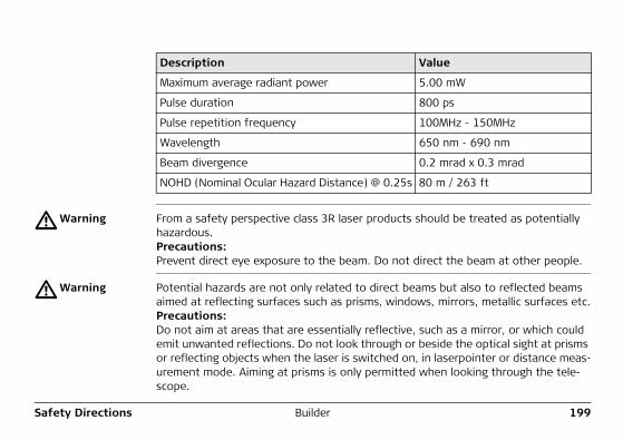
Safety Directions Builder 199
�Warning From a safety perspective class 3R laser products should be treated as potentially hazardous.Precautions:Prevent direct eye exposure to the beam. Do not direct the beam at other people.
�Warning Potential hazards are not only related to direct beams but also to reflected beams aimed at reflecting surfaces such as prisms, windows, mirrors, metallic surfaces etc.Precautions:Do not aim at areas that are essentially reflective, such as a mirror, or which could emit unwanted reflections. Do not look through or beside the optical sight at prisms or reflecting objects when the laser is switched on, in laserpointer or distance meas-urement mode. Aiming at prisms is only permitted when looking through the tele-scope.
Description Value
Maximum average radiant power 5.00 mW
Pulse duration 800 ps
Pulse repetition frequency 100MHz - 150MHz
Wavelength 650 nm - 690 nm
Beam divergence 0.2 mrad x 0.3 mrad
NOHD (Nominal Ocular Hazard Distance) @ 0.25s 80 m / 263 ft
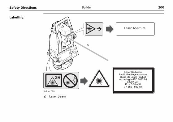
200BuilderSafety Directions
Labelling
a) Laser beam
Builder_080
a
Laser RadiationAvoid direct eye exposureClass 3R Laser Product
according to IEC 60825-1( 2007-03 )
Po ≤ 5.00 mWλ = 650 - 690 nm
Laser Aperture
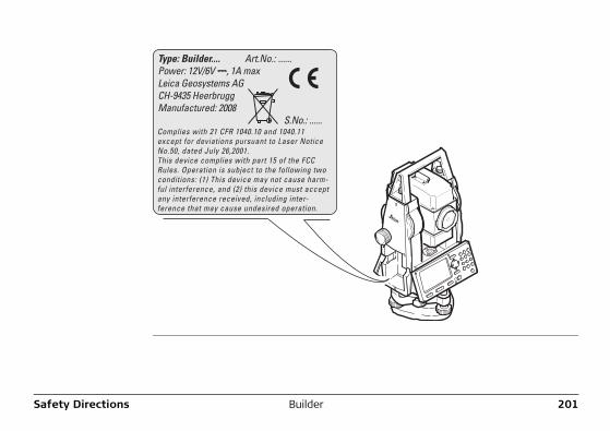
Safety Directions Builder 201
Type: Builder.... Art.No.: ......Power: 12V/6V ---, 1A maxLeica Geosystems AGCH-9435 HeerbruggManufactured: 2008 S.No.: ......Complies with 21 CFR 1040.10 and 1040.11 except for deviations pursuant to Laser Notice No.50, dated July 26,2001.This device complies with part 15 of the FCC Rules. Operation is subject to the following two conditions: (1) This device may not cause harm-ful interference, and (2) this device must accept any interference received, including inter-ference that may cause undesired operation.
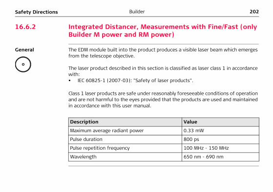
202BuilderSafety Directions
16.6.2 Integrated Distancer, Measurements with Fine/Fast (only Builder M power and RM power)
General The EDM module built into the product produces a visible laser beam which emerges from the telescope objective.
The laser product described in this section is classified as laser class 1 in accordance with:• IEC 60825-1 (2007-03): "Safety of laser products".
Class 1 laser products are safe under reasonably foreseeable conditions of operation and are not harmful to the eyes provided that the products are used and maintained in accordance with this user manual.
Description Value
Maximum average radiant power 0.33 mW
Pulse duration 800 ps
Pulse repetition frequency 100 MHz - 150 MHz
Wavelength 650 nm - 690 nm
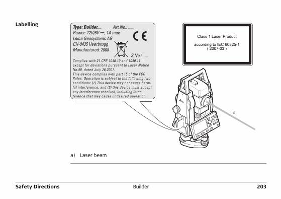
Safety Directions Builder 203
Labelling
a) Laser beam
Type: Builder.... Art.No.: ......Power: 12V/6V ---, 1A maxLeica Geosystems AGCH-9435 HeerbruggManufactured: 2008 S.No.: ......Complies with 21 CFR 1040.10 and 1040.11 except for deviations pursuant to Laser Notice No.50, dated July 26,2001.This device complies with part 15 of the FCC Rules. Operation is subject to the following two conditions: (1) This device may not cause harm-ful interference, and (2) this device must accept any interference received, including inter-ference that may cause undesired operation.
a
Class 1 Laser Product
according to IEC 60825-1( 2007-03 )
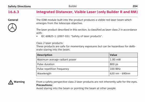
204BuilderSafety Directions
16.6.3 Integrated Distancer, Visible Laser (only Builder R and RM)
General The EDM module built into the product produces a visible red laser beam which emerges from the telescope objective.
The laser product described in this section, is classified as laser class 2 in accordance with:• IEC 60825-1 (2007-03): "Safety of laser products".
Class 2 laser products:These products are safe for momentary exposures but can be hazardous for delib-erate staring into the beam.
�Warning From a safety perspective class 2 laser products are not inherently safe for the eyes.Precautions:Avoid staring into the beam or pointing the beam at other people.
Description Value
Maximum average radiant power 1.00 mW
Pulse duration 800 ps
Pulse repetition frequency 100 MHz
Wavelength 620 nm - 690nm
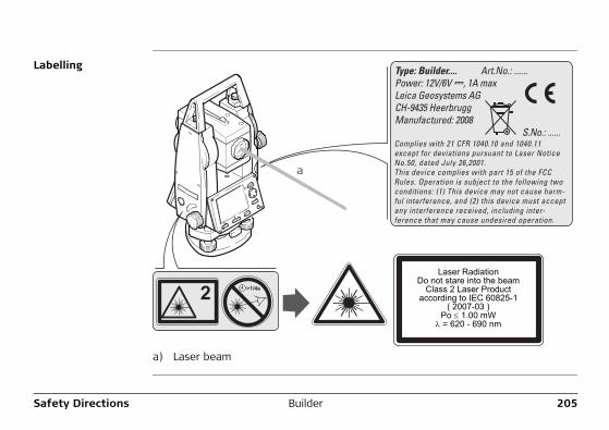
Safety Directions Builder 205
Labelling
a) Laser beam
T ype: Builder.... Art.No.: ...... Power: 12V/6V ---, 1A max Leica Geosystems AG CH-9435 Heerbrugg Manufactured: 2008 S.No.: ...... Complies with 21 CFR 1040.10 and 1040.11 except for deviations pursuant to Laser Notice No.50, dated July 26,2001. This device complies with part 15 of the FCC Rules. Operation is subject to the following two conditions: (1) This device may not cause harm- ful interference, and (2) this device must accept any interference received, including inte r - ference that may cause undesired operation.
a
Laser RadiationDo not stare into the beam
Class 2 Laser Productaccording to IEC 60825-1
( 2007-03 )Po ≤ 1.00 mW
λ = 620 - 690 nm
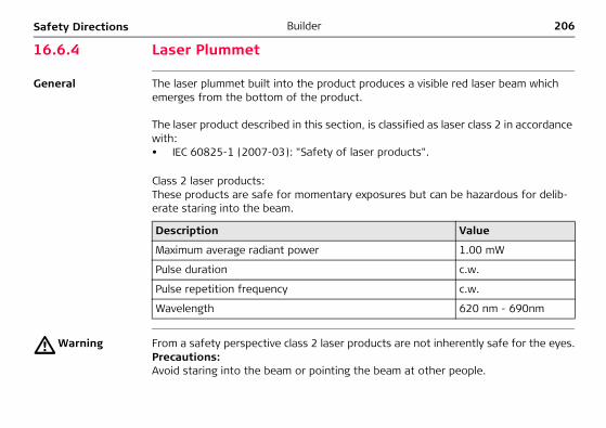
206BuilderSafety Directions
16.6.4 Laser Plummet
General The laser plummet built into the product produces a visible red laser beam which emerges from the bottom of the product.
The laser product described in this section, is classified as laser class 2 in accordance with:• IEC 60825-1 (2007-03): "Safety of laser products".
Class 2 laser products:These products are safe for momentary exposures but can be hazardous for delib-erate staring into the beam.
�Warning From a safety perspective class 2 laser products are not inherently safe for the eyes.Precautions:Avoid staring into the beam or pointing the beam at other people.
Description Value
Maximum average radiant power 1.00 mW
Pulse duration c.w.
Pulse repetition frequency c.w.
Wavelength 620 nm - 690nm
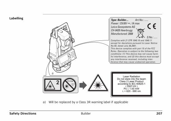
Safety Directions Builder 207
Labelling
a) Will be replaced by a Class 3R warning label if applicable
T ype: Builder.... Art.No.: ...... Power: 12V/6V ---, 1A max Leica Geosystems AG CH-9435 Heerbrugg Manufactured: 2008 S.No.: ...... Complies with 21 CFR 1040.10 and 1040.11 except for deviations pursuant to Laser Notice No.50, dated July 26,2001. This device complies with part 15 of the FCC Rules. Operation is subject to the following two conditions: (1) This device may not cause harm- ful interference, and (2) this device must accept any interference received, including inte r - ference that may cause undesired operation.
aLaser Radiation
Do not stare into the beamClass 2 Laser Product
according to IEC 60825-1( 2007-03 )
Po ≤ 1.00 mWλ = 620 - 690 nm
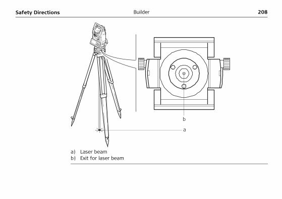
208BuilderSafety Directions
a) Laser beamb) Exit for laser beam
b
a
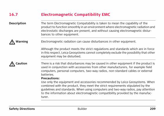
Safety Directions Builder 209
16.7 Electromagnetic Compatibility EMC
Description The term Electromagnetic Compatability is taken to mean the capability of the product to function smoothly in an environment where electromagnetic radiation and electrostatic discharges are present, and without causing electromagnetic distur-bances to other equipment.
�Warning Electromagnetic radiation can cause disturbances in other equipment.
Although the product meets the strict regulations and standards which are in force in this respect, Leica Geosystems cannot completely exclude the possibility that other equipment may be disturbed.
�Caution There is a risk that disturbances may be caused in other equipment if the product is used in conjunction with accessories from other manufacturers, for example field computers, personal computers, two-way radios, non-standard cables or external batteries.Precautions:Use only the equipment and accessories recommended by Leica Geosystems. When combined with the product, they meet the strict requirements stipulated by the guidelines and standards. When using computers and two-way radios, pay attention to the information about electromagnetic compatibility provided by the manufac-turer.
210BuilderSafety Directions
�Caution Disturbances caused by electromagnetic radiation can result in erroneous measure-ments.Although the product meets the strict regulations and standards which are in force in this respect, Leica Geosystems cannot completely exclude the possibility that the product may be disturbed by very intense electromagnetic radiation, for example, near radio transmitters, two-way radios or diesel generators.Precautions:Check the plausibility of results obtained under these conditions.
�Warning If the product is operated with connecting cables attached at only one of their two ends, for example external supply cables, interface cables, the permitted level of electromagnetic radiation may be exceeded and the correct functioning of other products may be impaired. Precautions:While the product is in use, connecting cables, for example product to external battery, product to computer, must be connected at both ends.
Safety Directions Builder 211
16.8 FCC Statement, Applicable in U.S.
�Warning This equipment has been tested and found to comply with the limits for a Class B digital device, pursuant to part 15 of the FCC rules.These limits are designed to provide reasonable protection against harmful interfer-ence in a residential installation.This equipment generates, uses and can radiate radio frequency energy and, if not installed and used in accordance with the instructions, may cause harmful interfer-ence to radio communications. However, there is no guarantee that interference will not occur in a particular installation.If this equipment does cause harmful interference to radio or television reception, which can be determined by turning the equipment off and on, the user is encour-aged to try to correct the interference by one or more of the following measures:• Reorient or relocate the receiving antenna.• Increase the separation between the equipment and the receiver.• Connect the equipment into an outlet on a circuit different from that to which
the receiver is connected.• Consult the dealer or an experienced radio/TV technician for help.
�Warning Changes or modifications not expressly approved by Leica Geosystems for compli-ance could void the user's authority to operate the equipment.
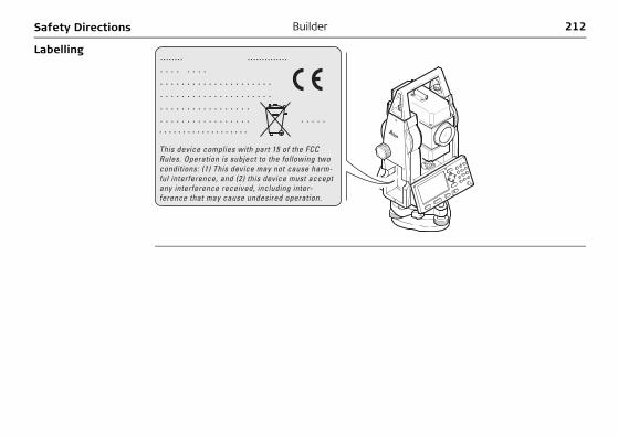
212BuilderSafety Directions
Labelling ........ .............. . . . . . . . . . . . . . . . . . . . . . . . . . . . . . . . . . . . . . . . . . . . . . . . . . . . . . . . . . . . . . . . . . . . . . . . . . . . . . . . . . . . . . . . . . . . . . . . . . . . . . . . . . . . .
This device complies with part 15 of the FCC Rules. Operation is subject to the following two conditions: (1) This device may not cause harm- ful interference, and (2) this device must accept any interference received, including inte r - ference that may cause undesired operation.

Safety Directions Builder 213
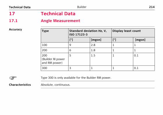
214BuilderTechnical Data
17 Technical Data17.1 Angle Measurement
Accuracy
Type 300 is only available for the Builder RM power.
Characteristics Absolute, continuous.
Type Standard deviation Hz, V, ISO 17123-3
Display least count
["] [mgon] ["] [mgon]
100 9 2.8 1 1
200 6 1.8 1 1
200 (Builder M power and RM power)
5 1.5 1 0.1
300 3 1 1 0.1
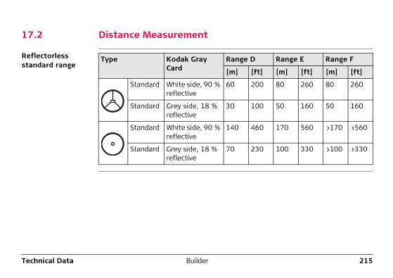
Technical Data Builder 215
17.2 Distance Measurement
Reflectorless standard range
Type Kodak Gray Card
Range D Range E Range F
[m] [ft] [m] [ft] [m] [ft]
Standard White side, 90 % reflective
60 200 80 260 80 260
Standard Grey side, 18 % reflective
30 100 50 160 50 160
Standard White side, 90 % reflective
140 460 170 560 >170 >560
Standard Grey side, 18 % reflective
70 230 100 330 >100 >330
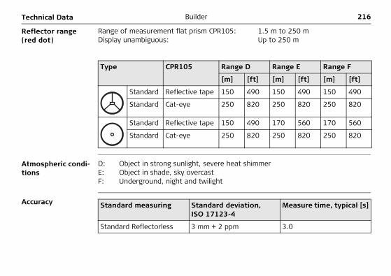
216BuilderTechnical Data
Reflector range (red dot)
Atmospheric condi-tions
Accuracy
Range of measurement flat prism CPR105: 1.5 m to 250 mDisplay unambiguous: Up to 250 m
Type CPR105 Range D Range E Range F
[m] [ft] [m] [ft] [m] [ft]
Standard Reflective tape 150 490 150 490 150 490
Standard Cat-eye 250 820 250 820 250 820
Standard Reflective tape 150 490 170 560 170 560
Standard Cat-eye 250 820 250 820 250 820
D: Object in strong sunlight, severe heat shimmerE: Object in shade, sky overcastF: Underground, night and twilight
Standard measuring Standard deviation, ISO 17123-4
Measure time, typical [s]
Standard Reflectorless 3 mm + 2 ppm 3.0
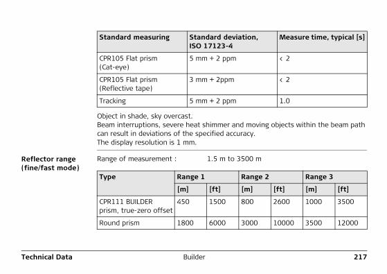
Technical Data Builder 217
Object in shade, sky overcast.Beam interruptions, severe heat shimmer and moving objects within the beam path can result in deviations of the specified accuracy.The display resolution is 1 mm.
Reflector range (fine/fast mode)
CPR105 Flat prism (Cat-eye)
5 mm + 2 ppm < 2
CPR105 Flat prism(Reflective tape)
3 mm + 2ppm < 2
Tracking 5 mm + 2 ppm 1.0
Standard measuring Standard deviation, ISO 17123-4
Measure time, typical [s]
Range of measurement : 1.5 m to 3500 m
Type Range 1 Range 2 Range 3
[m] [ft] [m] [ft] [m] [ft]
CPR111 BUILDER prism, true-zero offset
450 1500 800 2600 1000 3500
Round prism 1800 6000 3000 10000 3500 12000
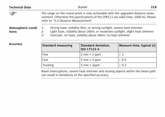
218BuilderTechnical Data
The range on the round prism is only achievable with the upgraded distance meas-urement. Otherwise the specifications of the CPR111 are valid (max. 1000 m). Please refer to "5.4 Distance Measurement".
Atmospheric condi-tions
Accuracy
Beam interruptions, severe heat shimmer and moving objects within the beam path can result in deviations of the specified accuracy.
1: Strong haze, visibility 5km; or strong sunlight, severe heat shimmer2: Light haze, visibility about 20km; or moderate sunlight, slight heat shimmer3: Overcast, no haze, visibility about 40km; no heat shimmer
Standard measuring Standard deviation, ISO 17123-4
Measure time, typical [s]
Fine 2 mm + 2 ppm < 1
Fast 5 mm + 2 ppm < 0.5
Tracking 5 mm + 2ppm < 0.3
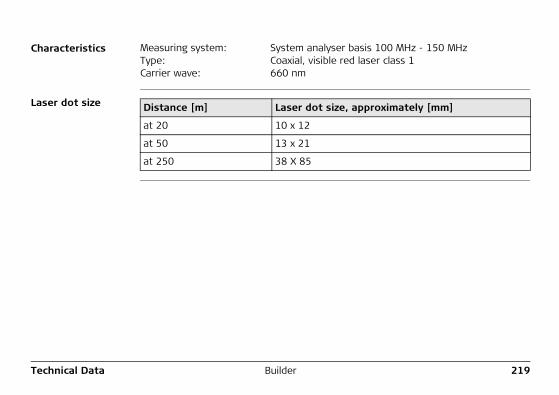
Technical Data Builder 219
Characteristics
Laser dot size
Measuring system: System analyser basis 100 MHz - 150 MHzType: Coaxial, visible red laser class 1Carrier wave: 660 nm
Distance [m] Laser dot size, approximately [mm]
at 20 10 x 12
at 50 13 x 21
at 250 38 X 85
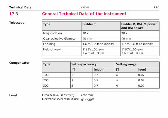
220BuilderTechnical Data
17.3 General Technical Data of the Instrument
Telescope
Compensator
Level
Type Builder T Builder R, RM, M power and RM power
Magnification 30 x 30 x
Clear objective diameter 40 mm 40 mm
Focusing 1.6 m/5.2 ft to infinity 1.7 m/5.6 ft to infinity
Field of view 1°21’/1.50 gon2.4 m at 100 m
1°30’/1.66 gon2.6 m at 100 m
Type Setting accuracy Setting range
["] [mgon] [’] [gon]
100 2 0.7 4 0.07
200 2 0.7 4 0.07
300 2 0.7 4 0.07
Circular level sensitivity: 6’/2 mmElectronic level resolution: 6" (=20cc)
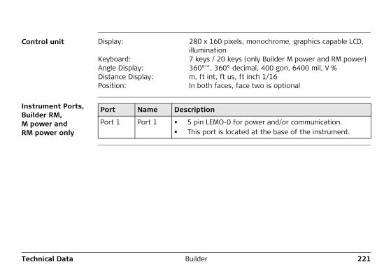
Technical Data Builder 221
Control unit
Instrument Ports, Builder RM, M power and RM power only
Display: 280 x 160 pixels, monochrome, graphics capable LCD, illumination
Keyboard: 7 keys / 20 keys (only Builder M power and RM power)Angle Display: 360°’", 360° decimal, 400 gon, 6400 mil, V %Distance Display: m, ft int, ft us, ft inch 1/16Position: In both faces, face two is optional
Port Name Description
Port 1 Port 1 • 5 pin LEMO-0 for power and/or communication.• This port is located at the base of the instrument.
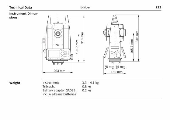
222BuilderTechnical Data
Instrument Dimen-sions
Weight
195.
7 m
m
316
mm
203 mm 75 mm 75 mm
195.
7 m
m
316
mm
150 mm
Instrument: 3.3 - 4.1 kgTribrach: 0.8 kgBattery adapter GAD39:incl. 6 alkaline batteries
0.2 kg
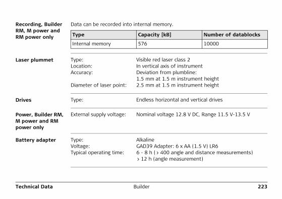
Technical Data Builder 223
Recording, Builder RM, M power and RM power only
Data can be recorded into internal memory.
Laser plummet
Drives
Power, Builder RM, M power and RM power only
Battery adapter
Type Capacity [kB] Number of datablocks
Internal memory 576 10000
Type: Visible red laser class 2Location: In vertical axis of instrumentAccuracy: Deviation from plumbline:
1.5 mm at 1.5 m instrument heightDiameter of laser point: 2.5 mm at 1.5 m instrument height
Type: Endless horizontal and vertical drives
External supply voltage: Nominal voltage 12.8 V DC, Range 11.5 V-13.5 V
Type: AlkalineVoltage: GAD39 Adapter: 6 x AA (1.5 V) LR6Typical operating time: 6 - 8 h (> 400 angle and distance measurements)
> 12 h (angle measurement)
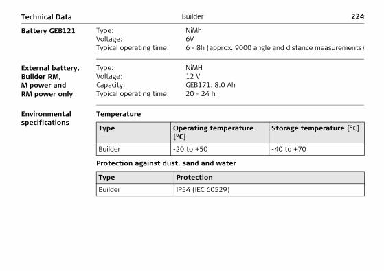
224BuilderTechnical Data
Battery GEB121
External battery, Builder RM, M power and RM power only
Environmental specifications
Temperature
Protection against dust, sand and water
Type: NiMhVoltage: 6VTypical operating time: 6 - 8h (approx. 9000 angle and distance measurements)
Type: NiMHVoltage: 12 VCapacity: GEB171: 8.0 AhTypical operating time: 20 - 24 h
Type Operating temperature [°C]
Storage temperature [°C]
Builder -20 to +50 -40 to +70
Type Protection
Builder IP54 (IEC 60529)
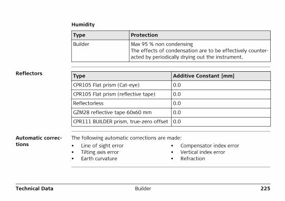
Technical Data Builder 225
Humidity
Reflectors
Automatic correc-tions
The following automatic corrections are made:
Type Protection
Builder Max 95 % non condensingThe effects of condensation are to be effectively counter-acted by periodically drying out the instrument.
Type Additive Constant [mm]
CPR105 Flat prism (Cat-eye) 0.0
CPR105 Flat prism (reflective tape) 0.0
Reflectorless 0.0
GZM28 reflective tape 60x60 mm 0.0
CPR111 BUILDER prism, true-zero offset 0.0
• Line of sight error • Compensator index error• Tilting axis error • Vertical index error• Earth curvature • Refraction

226BuilderInternational Limited Warranty, Soft-ware License Agreement
18 International Limited Warranty, Software License Agreement
International Limited Warranty
This product is subject to the terms and conditions set out in the International Limited Warranty which you can download from the Leica Geosystems home page at http://www.leica-geosystems.com/internationalwarranty or collect from your Leica Geosystems distributor. The foregoing warranty is exclusive and is in lieu of all other warranties, terms or conditions, express or implied, either in fact or by operation of law, statutory or otherwise, including warranties, terms or conditions of merchanta-bility, fitness for a particular purpose, satisfactory quality and non-infringement, all of which are expressly disclaimed.
Software License Agreement
This product contains software that is preinstalled on the product, or that is supplied to you on a data carrier medium, or that can be downloaded by you online pursuant to prior authorization from Leica Geosystems. Such software is protected by copy-right and other laws and its use is defined and regulated by the Leica Geosystems Software License Agreement, which covers aspects such as, but not limited to, Scope of the License, Warranty, Intellectual Property Rights, Limitation of Liability, Exclusion of other Assurances, Governing Law and Place of Jurisdiction. Please make sure, that at any time you fully comply with the terms and conditions of the Leica Geosystems Software License Agreement.
International Limited Warranty, Soft-ware License Agreement
Builder 227
Such agreement is provided together with all products and can also be referred to and downloaded at the Leica Geosystems home page at http://www.leica-geosys-tems.com/swlicense or collected from your Leica Geosystems distributor.
You must not install or use the software unless you have read and accepted the terms and conditions of the Leica Geosystems Software License Agreement. Installa-tion or use of the software or any part thereof, is deemed to be an acceptance of all the terms and conditions of such License Agreement. If you do not agree to all or some of the terms of such License Agreement, you may not download, install or use the software and you must return the unused software together with its accompa-nying documentation and the purchase receipt to the dealer from whom you purchased the product within ten (10) days of purchase to obtain a full refund of the purchase price.
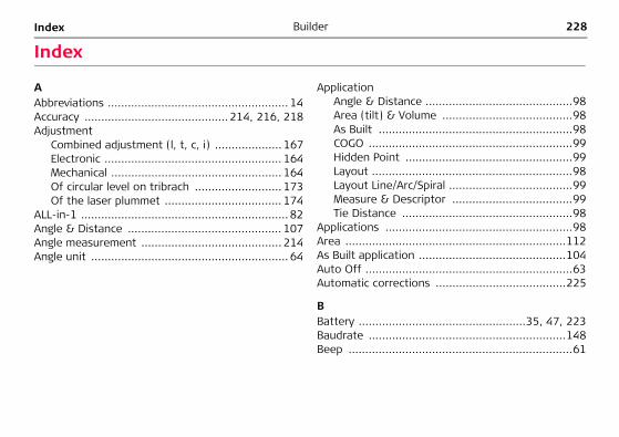
228BuilderIndex
Index
AAbbreviations ...................................................... 14Accuracy ........................................... 214, 216, 218Adjustment
Combined adjustment (l, t, c, i) .................... 167Electronic ..................................................... 164Mechanical ................................................... 164Of circular level on tribrach .......................... 173Of the laser plummet ................................... 174
ALL-in-1 .............................................................. 82Angle & Distance .............................................. 107Angle measurement .......................................... 214Angle unit ........................................................... 64
ApplicationAngle & Distance ............................................98Area (tilt) & Volume .......................................98As Built ..........................................................98COGO .............................................................99Hidden Point ..................................................99Layout ............................................................98Layout Line/Arc/Spiral .....................................99Measure & Descriptor ....................................99Tie Distance ...................................................98
Applications ........................................................98Area ..................................................................112As Built application ............................................104Auto Off ..............................................................63Automatic corrections .......................................225
BBattery ..................................................35, 47, 223Baudrate ...........................................................148Beep ...................................................................61
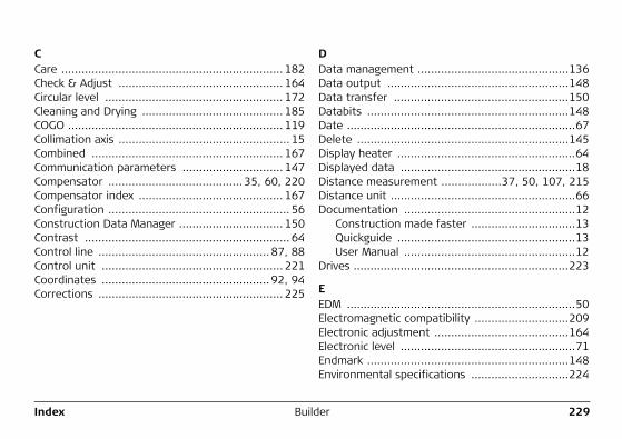
Index Builder 229
CCare .................................................................. 182Check & Adjust ................................................. 164Circular level ..................................................... 172Cleaning and Drying .......................................... 185COGO ................................................................ 119Collimation axis ................................................... 15Combined ......................................................... 167Communication parameters .............................. 147Compensator ........................................ 35, 60, 220Compensator index ........................................... 167Configuration ...................................................... 56Construction Data Manager ............................... 150Contrast ............................................................. 64Control line ................................................... 87, 88Control unit ...................................................... 221Coordinates .................................................. 92, 94Corrections ....................................................... 225
DData management .............................................136Data output ......................................................148Data transfer ....................................................150Databits ............................................................148Date ....................................................................67Delete ...............................................................145Display heater .....................................................64Displayed data ....................................................18Distance measurement ..................37, 50, 107, 215Distance unit .......................................................66Documentation ...................................................12
Construction made faster ...............................13Quickguide .....................................................13User Manual ...................................................12
Drives ................................................................223
EEDM ....................................................................50Electromagnetic compatibility ............................209Electronic adjustment ........................................164Electronic level ....................................................71Endmark ............................................................148Environmental specifications .............................224
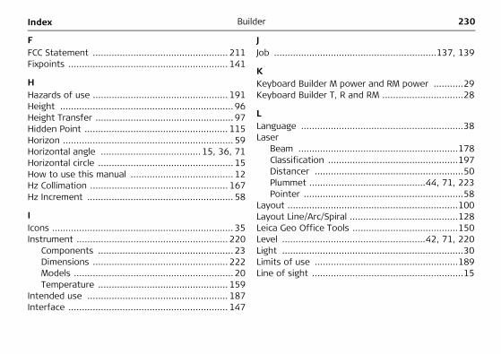
230BuilderIndex
FFCC Statement .................................................. 211Fixpoints ........................................................... 141
HHazards of use .................................................. 191Height ................................................................ 96Height Transfer ................................................... 97Hidden Point ..................................................... 115Horizon ............................................................... 59Horizontal angle ..................................... 15, 36, 71Horizontal circle .................................................. 15How to use this manual ...................................... 12Hz Collimation ................................................... 167Hz Increment ...................................................... 58
IIcons ................................................................... 35Instrument ........................................................ 220
Components .................................................. 23Dimensions .................................................. 222Models ........................................................... 20Temperature ................................................ 159
Intended use .................................................... 187Interface ........................................................... 147
JJob ............................................................137, 139
KKeyboard Builder M power and RM power ...........29Keyboard Builder T, R and RM ..............................28
LLanguage ............................................................38Laser
Beam ...........................................................178Classification ................................................197Distancer .......................................................50Plummet ...........................................44, 71, 223Pointer ...........................................................58
Layout ...............................................................100Layout Line/Arc/Spiral ........................................128Leica Geo Office Tools .......................................150Level .....................................................42, 71, 220Light ...................................................................30Limits of use .....................................................189Line of sight ........................................................15
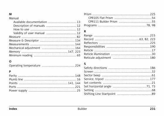
Index Builder 231
MManual
Available documentation ................................ 13Description of manuals .................................. 12How to use .................................................... 12Validity of user manual .................................. 12
Measure .............................................................. 82Measure & Descriptor ....................................... 134Measurements .................................................. 144Mechanical adjustment ..................................... 164Memory .................................................... 147, 223Minimum reading ................................................ 65
OOperating temperature ..................................... 224
PParity ................................................................ 148Plumb line ........................................................... 16Points ....................................................... 141, 144Ports ................................................................. 221Power supply ...................................................... 25
Prism .................................................................225CPR105 Flat Prism ..........................................54CPR111 Builder Prism .....................................55
Programs .......................................................78, 98
RRange ...............................................................215Record ..................................................63, 82, 223Reflectors .........................................................225Responsibilities .................................................190Reticle .................................................................17Reticle illumination ..............................................30Reticule adjustment ..........................................180
SSafety directions ...............................................186Screen .................................................................32Sector beep ........................................................61Service, tripod ...................................................177Set contents .......................................................21Set horizontal angle ......................................71, 73Setting ................................................................68Shifting Line Startpoint .......................................89
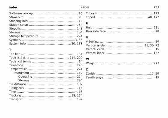
232BuilderIndex
Software concept ............................................... 26Stake out ............................................................ 98Standing axis ...................................................... 15Station setup ...................................................... 84Stopbits ............................................................ 148Storage ............................................................. 184Storage temperature ........................................ 224Symbols .......................................................... 3, 36System Info ................................................ 30, 158
TTab bar ............................................................... 34Technical data ........................................... 214, 220Technical terms ................................................... 14Telescope ......................................................... 220Temperature ..................................................... 224
Instrument ................................................... 159Operating ............................................... 224Storage ................................................... 224
Tie distance ...................................................... 109Tilting axis ........................................................... 15Time ................................................................... 67Tracking ...................................................... 58, 154Transport .......................................................... 182
Tribrach .............................................................173Tripod .........................................................40, 177
UUnit ...................................................................221User interface .....................................................28
VV Setting .............................................................59Vertical angle ..........................................15, 36, 72Vertical circle .......................................................15Vertical index .....................................................167
WWeight ..............................................................222
ZZenith ...........................................................17, 59Zenith angle ........................................................15
Index Builder 233

Total Quality Management: Our commitment to total customer satisfaction.
Leica Geosystems AG, Heerbrugg, Switzerland, has been certified as being equipped with a quality system which meets the International Standards of Quality Management and Quality Systems (ISO standard 9001) and Environmental Management Systems (ISO standard 14001).
Ask your local Leica dealer for more information about our TQM program.
7619
47-4
.0.0
en O
rigin
al t
ext
Prin
ted
in S
witz
erla
nd ©
200
8 Le
ica
Geo
syst
ems
AG, H
eerb
rugg
, Sw
itzer
land
Leica Geosystems AGHeinrich-Wild-StrasseCH-9435 HeerbruggSwitzerlandPhone +41 71 727 31 31www.leica-geosystems.com