Embed Size (px)
Citation preview

University of Michigan LEGACY Design Report
LEGACY
University of Michigan
2014 Concrete canoe design paper

University of Michigan LEGACY Design Report
TABLE OF CONTENTS
Executive Summary ii
Project Management 1
Organization Chart 2
Hull Design and Structural Analysis 3
Development & Testing 5
Construction 7
Project Schedule 9
Design Drawing 10
Appendix A: References A-1
Appendix B: Mixture Proportions B-1
Appendix C: Bill of Materials C-1
LIST OF TABLES
Table 1: Division of project man hours 1
Table 2: Resistance Calculation Summary 4
LIST OF FIGURES
Figure 1: 2014 Budget Allocation ii
Figure 2: Midship Cross Section 3
Figure 3: LEGACY Loading Cases 4
Figure 4: Canoe Gradient Thickness 4
Figure 5: Aggregate Measurement for Text Mixes 5
Figure 6: Formed Concrete Cylinders 5
Figure 7: Baseline Mix Gradation Curves 6
Figure 8: Fiber Separation 6
Figure 9: Mold Cutting using CNC Router 7
Figure 10: Mold Alignment 7
Figure 11: Quality Control Devices for Hull Thickness 8
Figure 12: Concrete Placement during Pour Day 8
Figure 13: Hand Sanding of Interior Hull Surface 8
i

University of Michigan LEGACY Design Report
Executive Summary
Founded in 1817, the University of Michigan of
Ann Arbor has long been established as one of the
nation’s premier research institutions. The opening
of the College of Engineering in 1854 served to
only further the college’s commitment to pursuing
the latest, cutting-edge technology. Tackling the
final frontier of space, the Apollo 15 mission, with
an all-University of Michigan manned crew and
NASA’s fourth lunar landing, solidified Michigan
as pioneers. Michigan Engineering faculty and
students have continued this legacy of research
and innovation, through student design teams such
as the Michigan Concrete Canoe Team (MCCT).
Facilities available through the Wilson Student
Project Team Center continue to give students
resources and opportunities to bring inventive
ideas into reality. The 2014 canoe, LEGACY, is
both a tribute to the Apollo 15 mission, and a
commitment to future endeavors.
The Apollo 15 mission was the first mission to use
a lunar rover, allowing the crew to explore more
of the moon than in previous missions. Similarly,
MCCT students explored previously unknown
territory at the 2013 North Central Regional
competition hosted by Michigan Technological
University, where they finished with an overall
placement of sixth place with the 2013 canoe
DREKAR. Previously, the 2012 canoe CRONUS
placed fourth overall and the 2011 canoe IT’S A
TRAP placed fifth overall.
MCCT’s newest endeavor, LEGACY, is manned
by a mixed crew of experienced veterans and new
recruits. The new members have brought many
skills and allowed the team to make significant
changes to the hull design of this year’s canoe to
reduce drag and increase paddler maneuverability.
This year’s hull design introduced a keel that
would help paddlers have better maneuvering in
the water during racing. The team switched the
mesh to one that was more pliable, and thus able
to conform to the new shape of the hull. In
addition, an emphasis was placed on increased
formal instruction and practice sessions for
paddlers to build endurance and group cohesion.
By scheduling an earlier pour day, the team’s
project schedule allowed more time to make fine
adjustments to the canoe and increased detail in
sanding.
Venturing into the unknown with the skills
necessary to chart a new course of discovery, the
Michigan Concrete Canoe Team presents the 2014
canoe LEGACY.
legacy
Weight 220 pounds
Length 19 feet, 8 inches
Width 28.5 inches
Depth 14 inches
Average Hull
Thickness 1 inch
Concrete Colors Gray
Concrete Unit
Weight
55.15 lb/ft3
(wet) /
55.13 lb/ft3
(dry)
Compressive
Strength 1030 psi
Split Tensile
Strength 250 psi
Reinforcement Fiberglass mesh
ii

University of Michigan LEGACY Design Report
Project Management
The goal for MCCT this year was for team
members develop experience in all areas of the
design process, thus supporting the longevity of
the team. As a result of this objective, quality
assurance was a major focus because many
members were involved in each area, and team
leads were charged with verifying all steps to
ensure guidelines were met for both safety and
feasibility.
This year’s project began on August 30, 2013 with
the first of the MCCT recruiting events. Once the
NCCC rules were released, hull design and mix
design began. The 2013-2014 project schedule
closely follows the outline set forth by the 2013
canoe, DREKAR. Milestone activities were
identified as the beginning of a new project phase
that supports the critical path events. The
following milestone activities were
identified: recruit new members, reach out for
sponsorship, mix & test concrete samples batches,
cut & assemble mold, place canoe, sand & de-
mold, stain and seal, and create display & stands.
The critical path events that supported the
completion of LEGACY are as follows: mass
meeting, finalize mix and hull design, construct
mold, place canoe, de-mold, complete aesthetic
design, and attend competition.
Risk of deviating from the critical path schedule
was assessed, and buffers between events were
applied appropriately to support the “place canoe”
event. The canoe was placed on December 7,
2013, on schedule to support the March
completion date.
Safety standards were met using guidelines from
ASTM and University of Michigan Facility usage.
All members were required to complete training
for respirator, project area, and concrete lab usage.
This year’s project was divided into four main
categories. An emphasis was placed on resource
acquisition because the team wanted new capital
goods such as paddles and a canoe carrier. Total
man hours for the project are divided as follows:
Table 1: Division of project man hours.
The budget for LEGACY was $8000, slightly
higher than that of last year’s canoe DREKAR.
Funding came from donations from local
companies for materials and sponsorship from
university departments and engineering societies.
Major expenses included construction material,
concrete material and capital expenses. This year,
additional resources were also applied for use on
more paddling practice, recruiting, and display
materials. The total cost of the project is $7500,
but will increase as competition approaches.
Task Hours
Research and Development (concrete
material, testing test cylinder
preparation and documenting findings)
210
Hull Design (3-D modeling, preparation
of CNC router sheets, analyzing
structure components)
150
Construction (cutting foam sheets, mold
assembly, pouring, testing, canoe
carrier and stand assembly, finishing
the canoe)
420
Resource Acquisition (recruiting new
members, finding potential sponsors,
purchasing materials and capital goods,
scheduling facility time)
100
1
Figure 1: 2014 budget allocations.
University of Michigan LEGACY Design Report
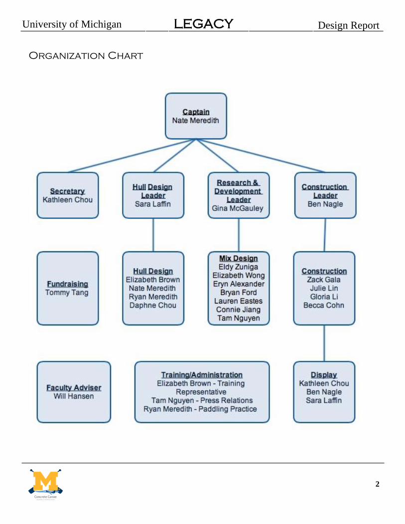
Organization Chart
2

University of Michigan LEGACY Design Report
Hull Design & Structural Analysis
This year, the team began the design of LEGACY
with a different approach from previous years in
order to meet our design criteria. MCCT wanted to
include new members in the design process while
building an efficient hull that would track better
through the water while making it easy for
paddlers to propel the boat through the water.
The first step in design was to take the Standard
Hull Form and use Maxsurf Stability Suite to
parametrically transform the hull for different
beam-to-length ratios. This would create a
database of principal dimensions that would allow
us to better understand the acting bending moment
once a cross section was determined.
When picking the cross section, the entire team
was involved. The team was looking for
innovative designs, so a few meetings were
dedicated to have members sketch out different
cross sections they felt would be the best for
speed, paddler comfort, and minimize acting
stresses. From the collected results, the cross
sections were analyzed in Rhinoceros 5.0 for the
section modulus which would later be used with
the regression of the principal dimensions. This
was a great opportunity to teach new members the
computer programs we rely on, as well as the
driving equations considered during canoe design.
There were several important considerations when
designing LEGACY. A narrower beam was desired
to increase speed, tracking, and allow for easier
paddler reach. Using the database created above, a
beam of 28.5 inches was decided upon as it
minimized bending moment under the max
bending moment configuration of the male sprint
race.
With a narrower beam, stability became more of
an issue with the design. The outward curvature of
walls of the canoe, flare, was added to help
counteract the beam. Flare will increase stability
when rolling because the righting arm increases
faster compared to a standard canoe hull form.
The final cross section design chosen for LEGACY
is shown in Figure 2.
Figure 2: Midship cross section of LEGACY.
With these new design changes and a unique cross
section, the strength of LEGACY was ensured by
increasing the hull thickness from the previous
year. The team decided on a minimum hull
thickness of 0.75 inches along the keel to a
maximum thickness of 1.2 inches along the
gunwale. The purpose of this gradient thickness is
to decrease the maximum bending arm and
minimize the stress along the gunwale when the
canoe is in tension. The driving factor was the
unconventional hull shape, with extra curvature
around the keel. Figure 4 portrays the design of
the gradient thickness of the hull.
Seven different loading conditions were analyzed
when considering the strength of LEGACY.
Moments were calculated for the following
conditions: male, female, and co-ed race
conditions, an unloaded canoe in the water, the
canoe in the transport carrier, the canoe on its race
day stands, and the display day stands.
The tensile stress in the gunwales was calculated
using the maximum distance from the neutral axis,
D, the moment of inertia, I, and the global bending
moment, M, as seen in Equation 1 below.
Distributed weight, buoyancy, and point loads
were analyzed to find the global bending moment.
3
(Eqn. 1)

University of Michigan LEGACY Design Report
Maxsurf Stability Suite was used to analyze the
difference between buoyant force and distributed
weight to calculate tensile strength along the
length of the canoe The maximum value, out of all
loading conditions, was found to be around 756 ft-
lbs. Using this value with the stress formula, the
maximum tensile force in the gunwale of
LEGACY will be about 96 psi. With a concrete
tensile strength of 250 psi, the safety factor for this
year’s design is 2.6.
The next analysis focused on resistance
calculations. Assuming approximately smooth
conditions after sanding and sealing the canoe, the
frictional resistance coefficient, , can be
approximated using the skin friction line
developed by the International Towing Tank
Conference (ITTC 1978), shown in Equation 2.
( ( ) )
, is the length Reynolds number dependent on
the kinematic viscosity, v and forward velocity V
which can be found below.
With the CF coefficient, the frictional resistance,
R, can be found using the Equation 3 below.
Where is density of water and S is the wetted
surface area.
Using this approximation, the frictional resistance
component was calculated to be 1.69 pound-force.
A summary of these calculations is shown in
Table 2 below.
Table 2: Resistance calculation summary.
4
Figure 4: The final view of canoe with the thicknesses marked.
Figure 3: Loading cases for LEGACY.
(Eqn. 2)
(Eqn. 3)

University of Michigan LEGACY Design Report
Development & Testing
MCCT’s ultimate goals for this year were to
develop a concrete mix with a density less than
that of water, while maximizing the tensile
strength of the mix. To accomplish this, MCCT
tested three different proportions of aggregate to
see their effects on these two metrics. Another
major focus was to look for an optimal mix of our
different cementitious materials including one that
had not used before, VCAS, by varying the
material quantities. Other elements altered
included a new type of fiber that was tested in
different quantities and experimented with a mix
of two fiber lengths. The second approach lead to
lower tensile strengths, so testing was
discontinued.
Aggregates used in all three baselines included
K20, three sizes of Poraver (0.25 - 0.5, 0.5 - 1.0,
and 1.0-2.0), SG 900, and G850. The major
change from last year’s mix was the removal of
Haydite, an expanded shale that MCCT has used
for several years. It was removed because its
properties were not as uniform as the other
materials. More uniformity allowed the team to
better control what variabilities were tested. A
second change was the switch from using K1 glass
microspheres to K20. The K20 is a slightly denser
aggregate, but this was compensated by the
increase in strength it lent to the mix. The final
concrete mix had good workability that allowed
the team to easily smooth it over our mold during
the canoe’s construction.
MCCT’s cementitious materials included Portland
Cement Type I, Ground Granulated Blast Furnace
Slag (GGBFS), and Komponent. GGBFS, a
locally available steel production by-product as a
sustainable, recycled, cementitious material, was
used again. Rice Husk Ash was removed from this
year’s mix to create a lighter final color which
allows for more flexibility when staining the
canoe.
To create the baseline mix for this year, MCCT
analyzed the mixes used by other teams over the
past three years. The goal to drastically improve
both the design’s strength and density encouraged
developing a mix vastly different from last year.
The percentage of aggregate in the mix was set at
60% and the use of Portland cement as 40% of our
cementitious material. Admixture dosages were
kept constant from last year as the results obtained
helped decrease the density and increase
workability and strength. The admixtures used in
LEGACY were Glenium 7500 and AE90, a
superplasticizer and air entrainer, respectively.
The major change for the LEGACY mix was to use
an innovative approach to select the aggregate
distribution. The first mix had a flat gradation with
equal percent of small and large aggregate
(Baseline One). Modifications were made to test
one mix which increased the percentage of small
aggregate (Baseline Two) and a second one which
increased the percentage of large aggregate
(Baseline Three). A rough sketch of the three
gradation curves can be seen in Figure 6. These
curves are theoretical and not calculated; the size
plotted on the graph is the estimated average size
5
Figure 5: Measuring aggregates and
cementitious materials.
Figure 6: Formed cylinders during testing.

University of Michigan LEGACY Design Report
of each aggregate. This innovative approach for
MCCT allowed the team to visualize the
differences in the three baseline mixes. Baseline
One, the flattest gradation, resulted in a
significantly lower strength. The second baseline
had a strength similar to last year’s, but a low
enough density to float. The third baseline had a
compressive strength of about 1400 psi
(approximate tensile strength of 280 psi) which
exceeded our desired improvement, but was too
dense to float.
Fifteen subsequent test batches were mixed to try
to create a mix that had the high strength of
Baseline Three with the low density of Baseline
Two. Cylinders were made from each test batch,
and tested for 28-day strength according to ASTM
C109. Modifications to each batch focused on the
effect variations on the distribution of the
cementitious material: Portland Cement Type I,
GGBFS, and VCAS. The effect of using a single
aggregate for the smallest size instead of two
similar aggregates (G850 and K20) was tested.
Using solely K20 significantly improved the
strength of Baseline Three, but did not have the
same desired effect on Baseline Two. Four
additional batches were mixed to test different
fibers as mentioned earlier. Polypropylene (PP)
fibers were tested against the polyvinyl alcohol
(PVA) fibers that have been used for the past
several years.
After analyzing the results of all tests, MCCT
decided that the original Baseline Two mix had
the best combination of low density and high
strength. The final mix modified Baseline Two by
switching to PP fibers and increasing the amount
of fibers in the mix. Cylinders made on Pour Day
were tested for their 28-day compressive strength
per ASTM standards, which was 1030 psi. While
this is lower than the strength from last year, the
tensile strength for this mix increased from last
year to 250 psi. The decrease in compressive
strength is acceptable for the structural integrity of
the canoe, especially with the increase in tensile
strength which was achieved. The final mix
achieved our primary goal of a mix that was less
dense than water. It also highly workable,
allowing us to better control for thickness and
uniformity on Pour Day.
MCCT decided to use Spiderlath Fiberglass Mesh
as reinforcement for the canoe this year for several
reasons. To begin with, Spiderlath is lighter, is
thinner, has a higher strength ratio, and is more
flexible than mesh MCCT has used in the past.
Additionally, the use of Spiderlath by several
other teams in the conference has proven that it
successfully prevents cracking with its high tensile
strength. Finally, Spiderlath meets all competition
requirements for open area and reinforcement
standards. As MCCT designs more unique canoes,
a mesh that can evolve with design complexity
and remain sustainable was an important factor
when picking a new mesh this year.
6
Figure 8: Separating fibers for varying
proportions in each text mix.
Figure 7: Qualitative gradation curves
for Baseline mixes.

University of Michigan LEGACY Design Report
Construction
This year’s construction method for LEGACY
followed that of the previous year. The team used
a male mold for the canoe, decreasing the amount
of foam used and improving concrete adhesion
during construction to mitigate the effects of
slump on canoe thickness. To create the mold, a
3-D model of the canoe was created in Rhinoceros
5.0, which was then split into 85 cross sections of
3 inch thickness. Use of 3 inch foam rather than
previous 2 inch foam for the mold helped reduce
costs for MCCT due to purchasing fewer foam
sheets and shorter CNC router cutting time. These
sections were then laid into 4’ x 8’ sections, along
with cutouts to fit three 2” x 4” alignment beams,
and a CNC router was used to cut the individual
pieces from a foam sheet. Flat bottom sections
that had molds for the gunwale and alignment
beams were added this year for easier removal of
the mold once sanding was completed. To ensure
the absolute accuracy of the mold, all sections
were cut three-dimensionally to within 1/32 of an
inch, using a spherically tipped drill bit.
One innovation for this year’s construction
involved aligning the mold using three offset
spines instead of a single spine in previous
years. Three 2” x 4” beams were used to align the
vertical cutouts together and in the correct position
on the bottom, horizontal piece of the
mold. Three beams provided a greater alignment
and ensured that there could be no twisting in the
hull, an issue seen in previous years. The beams
were offset to make correct mold placement easier
(if a cross section was placed on the wrong side, it
would not fit on top of the beams) and ensure
better alignment in both the lateral and horizontal
directions.
The mold was placed on pre-leveled tables,
aligned with the three alignment beams, and glued
together using wood glue. The mold was lightly
sanded, and the outer surface of the male mold
was then covered in a layer of double wide duct
tape, which makes de-molding much easier.
Unlike previous years, Pour Day for LEGACY was
scheduled for the end of the fall semester. This
was advantageous because this allowed LEGACY
to cure over winter break, which allowed sanding
to begin at the very beginning of the winter
semester. This placed the team several weeks
ahead of schedule in relation to previous years,
allowing for a greater focus on detailed sanding
and more time for other components such as the
stands and display.
On Pour Day, 0.3 ft3 batches of the chosen
concrete were pre-measured and mixed. The
concrete was then laid in a 3/8” first layer by
hand, followed by a layer of fiberglass mesh for
reinforcement. The mesh was laid in 3 foot
sections with a 2 inch overlap, ensuring that there
were not weaknesses due to gaps in mesh
Figure 9: Cutting out male mold using CNC router.
Figure 10: Aligning mold pieces on 2” x 4” beams.
7

University of Michigan LEGACY Design Report
reinforcement. Latex was sprayed on the first layer
after application to aid in the bonding of the two
layers and the mesh. A final layer was then laid
on, which was 3/8” on the bottom and ends, but
thicker on the center walls due to the gradient
gunwale. This layer was compacted by hand and
smoothed using trowels.
Three sizes of quality control devices were used to
ensure an even thickness in LEGACY’s hull. They
consisted of a nail pushed through a cork, with the
protruded end of the nail being either 3/8”, 3/4”,
or 1”. The 3/8” quality control device was used
for the first layer of concrete, while the 3/4”
device was used for the second layer. The 1”
device was used to make sure our gradient
thickness of the gunwale was correct. Four team
members were assigned as “Quality Control
Managers”. These members constantly checked
the hull thickness throughout the day, at all stages
of construction. This job was more essential than
in past years due to the difficulty in thickness
consistency caused by LEGACY’s protruding keel.
After placement, the concrete was wet-cured in a
temperature controlled environment for fourteen
days. Once cured, the canoe exterior was
thoroughly sanded, using both power sanders and
hand sanding. After the outer hull had been well
sanded, LEGACY was demolded and placed in a
female mold, which was created using the same 3-
D modeling and CNC cutting as the mold. The
inner hull was then sanded. The canoe will be
stained with a design in accordance with our space
exploration theme, and then sealed to protect the
aesthetic design. The canoe will be swamp tested
to determine whether or not additional flotation
will be necessary.
Sustainability was considered a focus for this
year’s project, which was achieved through
selection of cementitious materials and
procurement of materials. Leftover materials from
previous years were utilized to lower costs of the
overall project. Additionally, MCCT worked to
purchase materials such as wood and Portland
cement from nearby suppliers to reduce
environmental effects of shipping and support
local businesses.
Figure 11: Three sizes of quality control devices
for hull thickness measurement.
Figure 12: Placing concrete and checking
hull thickness on Pour Day.
Figure 13: Hand sanding the interior of
LEGACY after demolding.
8


University of Michigan LEGACY Design Report
Project Schedule
9
9

University of Michigan LEGACY Design Report
Design Drawing
10

University of Michigan LEGACY Design Report
Appendix A: References
(1992). “The Reynolds Number: About Rowing and Flying.” <http://www.aerodrag.com/Articles/ReynoldsNumber.htm> (Oct. 12, 2013). (2011). “Canoe Design”. < http://www.canoeing.com/canoes/choosing/design.htm> (Oct. 10, 2013). (2007). “3M Scotchlite Glass Bubbles: K and S series”. <http://multimedia.3m.com/mws/mediawebserver?mwsId=SSSSSufSevTsZxtUnxme4Y_9evUqevTSevTSevTSeSSSSSS--&fn=GlassBubbles%20KandS%20Series.pdf> (Sept. 10, 2013). ACI. (2008). “ACI 318-08 Building Code Requirements for Structural Concrete.” American Concrete Institute. Farmington Hills, Michigan. ASCE/NCCC. (2014). “2014 American Society of Civil Engineers National Concrete Canoe Competition.
Rules and Regulations.”
<http://www.asce.org/uploadedFiles/Concrete_Canoe/Rules_and_Regulations/2014%20ASCE%20NCCC%
20Rules%20and%20Regulations.pdf > (Feb. 15, 2014). ASTM. (2004). “Standard Test Method for Splitting Tensile Strength of Cylindrical Concrete Specimens.” C496/C496M-11, West Conshohocken, Pennsylvania. ASTM. (2010). “Standard Specification for Air-Entraining Admixtures for Concrete.” C260/C260M-10a, West Conshohocken, Pennsylvania. ASTM. (2010). “Standard Specification for Fiber-Reinforced Concrete.” C1116/C1116M-10a, West Conshohocken, Pennsylvania. ASTM. (2012). “Standard Practice for Making and Curing Concrete Test Specimens in the Field.” C31/C31M-12, West Conshohocken, Pennsylvania. ASTM. (2012). “Standard Specification for Portland Cement.” C150/C150M, West Conshohocken, Pennsylvania. ASTM. (2012). “Standard Test Method for Compressive Strength of Cylindrical Concrete Specimens.” C39/C39M-12a, West Conshohocken, Pennsylvania. ASTM. (2012). “Standard Test Method for Density, Relative Density (Specific Gravity), and Absorption of Coarse Aggregate.” C127-12, West Conshohocken, Pennsylvania. ASTM. (2012). “Standard Test Method for Density, Relative Density (Specific Gravity), and Absorption of Fine Aggregate.” C128-12, West Conshohocken, Pennsylvania. ASTM. (2013). “Standard Specification for Chemical Admixtures for Concrete.” C494/C494M-13, West Conshohocken, Pennsylvania. ASTM. (2013). “Standard Specification for Concrete Aggregates.” C33/C33M-13, West Conshohocken, Pennsylvania. ASTM. (2013). “Standard Specification for Slag Cement for Use in Concrete and Mortars.” C989/C989M-13, West Conshohocken, Pennsylvania. ASTM. (2013). “Standard Test Method for Compressive Strength of Hydraulic Cement Mortars.” C109/C109M-13, West Conshohocken, Pennsylvania.
A-1

University of Michigan LEGACY Design Report
ASTM. (2013). “Standard Test Method for Density (Unit Weight), Yield, and Air Content (Gravimetric) of Concrete.” C138/C138M-13a, West Conshohocken, Pennsylvania. Bacon, G. (2005). “Hubble Spots Possible New Moons around Pluto”.
<http://www.nasa.gov/vision/universe/solarsystem/hubble_pluto.html> (Jan. 5, 2014). Cal Poly Concrete Canoe. (2012). “Andromeda.” NCCC Design Paper, California Polytechnic State University, Pomona, California. (1999). “1978 ITTC Performance Prediction Method.” International Towing Tank Conference, Society of Naval Architects and Marine Engineers, Alexandria, Virginia, 1-31. Michigan Concrete Canoe Team. (2011). “It’s a Trap.” NCCC Design Paper, University of Michigan, Ann Arbor, Michigan. Michigan Concrete Canoe Team. (2012). “Cronus.” NCCC Design Paper, University of Michigan, Ann Arbor, Michigan. Michigan Concrete Canoe Team. (2013). “Drekar.” NCCC Design Paper, University of Michigan, Ann Arbor, Michigan. Michigan Tech Concrete Canoe. (2012). “Genoa.” NCCC Design Paper, Michigan Technological University, Houghton, Michigan. Raphael, J. M. (1984). “Tensile Strength of Concrete.” < http://www.concrete.org/tempComDocs/1237910-5818/81-17.pdf>. (Nov. 12, 2012). Slade, Stuart. (1998). “Understanding the Prismatic Coefficient”. <http://www.navweaps.com/index_tech/tech-004.htm>. (Oct. 13, 2012). University of Nevada Concrete Canoe. (2012). “Ducimus.” NCCC Design Paper, University of Nevada,
Reno, Nevada.
University of Wisconsin-Madison Concrete Canoe Team. (2011). “Element.” NCCC Design Paper,
University of Wisconsin-Madison, Madison, Wisconsin.
A-2

University of Michigan LEGACY Design Report
Appendix B: Mixture Proportions
B-1

University of Michigan LEGACY Design Report
Appendix C: Bill of Materials
Material Quantity
(lbs) Unit Cost Total Price
Federal White Portland Cement Type I 40.43 0.27 $10.92
NewCem® GGBFS 45.5 0.05 $2.28
Komponent 15.21 0.24 $3.65
PP Fiber 1.17 7 $8.19
K20 13.52 5.4 $73.01
SG-900 6.11 6.25 $38.19
G850 4.68 0.55 $2.57
Poraver® 0.5-1 mm 10.92 0.7 $7.64
Poraver® 0.25-0.5 7.28 0.7 $5.10
Poraver® 1.0 - 2.0 18.2 0.7 $12.74
Sikalatex 14.5 1.29 $18.71
ADVA Cast 555 0.56 12.38 $6.93
Darex II 0.2 9.37 $1.87
Fiberglass Mesh (sq ft) 42 0.5 $21.00
CR-WRC Stain (oz) 40 1.88 $75.00
Sealer (gal) 2 24.25 $48.50
Paint for Lettering (oz) 4 2.5 $10.00
Foam Mold, Complete 1 mold 813 $813.00
Sand Paper 1 pack 28 $28.00
Total Production Cost $1,187.29
C-1