Embed Size (px)
Citation preview
Skid Resistance Strategy Page 1
LEEDS CITY COUNCIL SKID RESISTANCE STRATEGY
OCTOBER 2019

Skid Resistance Strategy Page 2
Contents
Document Information ______________________________________________________________ 3
Document History __________________________________________________________________ 3
1. Introduction __________________________________________________________________ 4
Part A. The WYCA+ Common Skid Resistance Policy _____________________________________
Part B. Leeds City Council Skid Resistance Procedure ____________________________________
Skid Resistance Strategy Page 3
Document Information
Title (Sub Title) Skid Resistance Strategy
Product Number 001
Author Richard Hobson
Description Skid Resistance Strategy – Following the release of HD28/15 &
creation of the WYCA+ Common Skid Resistance Policy & Leeds City
Council Skid Resistance Procedure
Document History
Version
No
Status Author Date Changes from Previous Version
01 Draft R Hobson December
2018
First release for internal review
02 Draft R Hobson October 2019 WYCA Policy -Section 4 – comments
re replacement of HD28/15 with
CS228
Skid Resistance Strategy Page 4
1. Introduction
The Leeds City Council Skid Resistance Strategy comprises of 2 parts, the WYCA+ Common Skid
Resistance Policy and a Skid Resistance Procedure
Part A – WYCA+ Common Skid Resistance Policy
The constituent local authorities of the West Yorkshire Combined Authority (WYCA) – including
Leeds City Council, Kirklees Council, Bradford Metropolitan District Council, Calderdale Council
and Wakefield Council with the inclusion of City of York Council, henceforth referred to as the
WYCA+ for simplicity, have developed a common skid resistance policy. A common policy
ensures consistency on cross boundary networks, such as the West Yorkshire Key Route
Network, whilst the format allows each local authority the autonomy to manage their network
appropriate to the local conditions in accordance with their skid resistance procedure.
The policy takes an asset management approach to managing skid resistance and puts a greater
emphasis on engineering assessment. It will provide documented evidence of the local
authority proactive approach to skid resistance management.
Part B – LCC Skid Resistance Procedure
This document is a supplementary document to the WYCA+ Common Skid Resistance Policy. It
has been produced to provide a step by step approach to identifying skid deficient sites and sets
out a process for deciding on their subsequent treatment, and how this will be prioritized taking
into account budget and programme considerations in Leeds. The procedures in this Skid
Resistance Procedure set out a long-term strategy to manage the skid resistance of Leeds City
Council’s strategic network to a consistent and safe level. The procedure complements the
Council’s Highway Infrastructure Asset Management Strategy, which looks to manage assets in
a strategic way.
WYCA+ Common Skid Resistance Policy
XAIS Asset Management Ltd Company No: 09537184 Page 5
WEST YORKSHIRE COMBINED AUTHORITY COMMON SKID RESISTANCE POLICY
OCTOBER 2019
WYCA+ Common Skid Resistance Policy
XAIS Asset Management Ltd Company No: 09537184 Page 6
Contents
Document Information ______________________________________________________________ 7
Document History __________________________________________________________________ 7
1. Introduction __________________________________________________________________ 8
2. Skid Resistance ________________________________________________________________ 9
3. The WYCA+ Common Skid Resistance Policy ________________________________________ 10
4. Skid Resistance Procedure ______________________________________________________ 11
5. Responsibilities _______________________________________________________________ 13
5.1. Legal responsibilities _________________________________________________________ 13
5.2. Roles and Responsibilities _____________________________________________________ 13
WYCA+ Common Skid Resistance Policy
XAIS Asset Management Ltd Company No: 09537184 Page 7
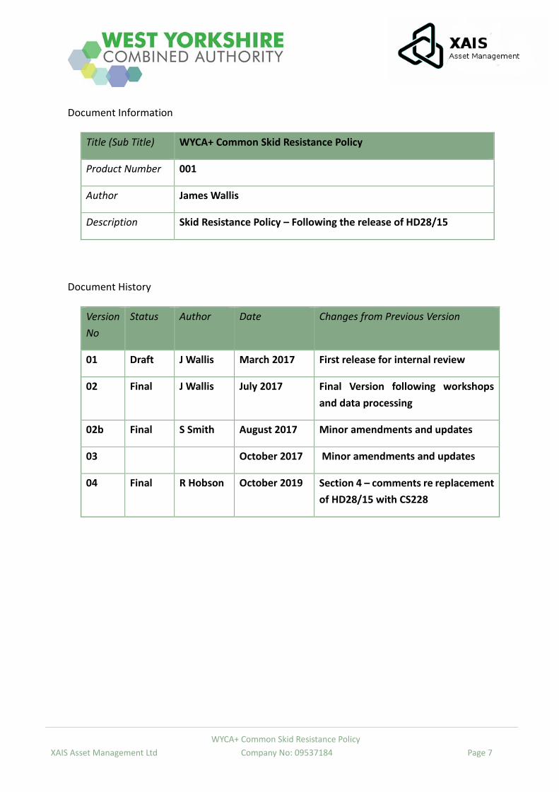
Document Information
Title (Sub Title) WYCA+ Common Skid Resistance Policy
Product Number 001
Author James Wallis
Description Skid Resistance Policy – Following the release of HD28/15
Document History
Version
No
Status Author Date Changes from Previous Version
01 Draft J Wallis March 2017 First release for internal review
02 Final J Wallis July 2017 Final Version following workshops
and data processing
02b Final S Smith August 2017 Minor amendments and updates
03 October 2017 Minor amendments and updates
04 Final R Hobson October 2019 Section 4 – comments re replacement
of HD28/15 with CS228
WYCA+ Common Skid Resistance Policy
XAIS Asset Management Ltd Company No: 09537184 Page 8
1. Introduction
The constituent local authorities of the West Yorkshire Combined Authority (WYCA) – including
Leeds City Council, Kirklees Council, Bradford Metropolitan District Council, Calderdale Council
and Wakefield Council with the inclusion of City of York Council, henceforth referred to as the
WYCA+ for simplicity, have developed a common skid resistance policy. A common policy
ensures consistency on cross boundary networks, such as the West Yorkshire Key Route
Network, whilst the format allows each local authority the autonomy to manage their network
appropriate to the local conditions in accordance with their skid resistance procedure.
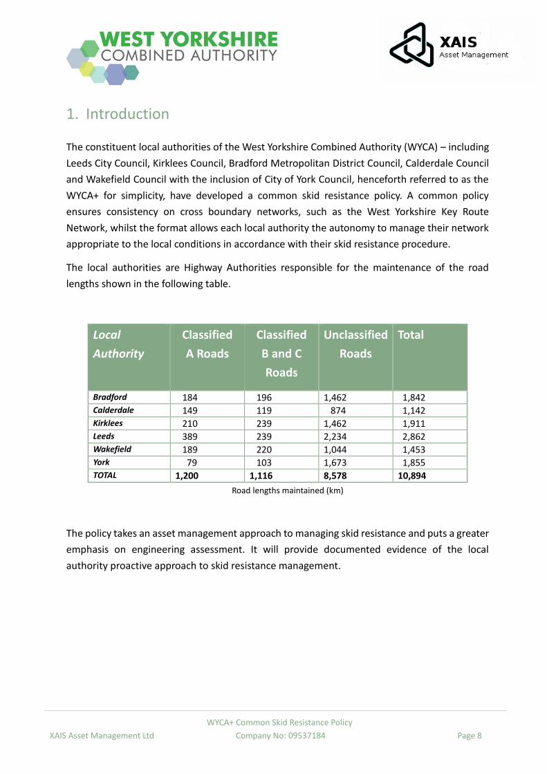
The local authorities are Highway Authorities responsible for the maintenance of the road
lengths shown in the following table.
Local
Authority
Classified
A Roads
Classified
B and C
Roads
Unclassified
Roads
Total
Bradford 184 196 1,462 1,842 Calderdale 149 119 874 1,142 Kirklees 210 239 1,462 1,911 Leeds 389 239 2,234 2,862 Wakefield 189 220 1,044 1,453 York 79 103 1,673 1,855 TOTAL 1,200 1,116 8,578 10,894
Road lengths maintained (km)
The policy takes an asset management approach to managing skid resistance and puts a greater
emphasis on engineering assessment. It will provide documented evidence of the local
authority proactive approach to skid resistance management.
WYCA+ Common Skid Resistance Policy
XAIS Asset Management Ltd Company No: 09537184 Page 9
2. Skid Resistance
The term “skid resistance” used in this document refers to the frictional properties of a road
surface in wet conditions, measured using a specified device, under standardised conditions.
Skid resistance testing is carried out on wet or damp surfaces as the skid resistance of a surface
will be substantially lower than when the same surface is dry.
Skid resistance is an important property relating to the safe passage of highway users,
particularly in damp or wet conditions. Over the course of a road’s life the surface can lose some
of its characteristics associated with grip. Effective maintenance of the highway network
includes the requirement to systematically monitor the skid resistance of the road surface and
to take a proactive approach so that the skid resistance across the network is maintained to an
appropriate standard.
Skid resistance measurements are used as an empirical assessment of a road surface’s level of
grip and as an indication of the potential need for further investigation based on known
acceptable limits. However, it should be noted it does not represent the definitive grip available
to a road user making a particular manoeuvre at a particular time and at a particular speed.
WYCA+ Common Skid Resistance Policy
XAIS Asset Management Ltd Company No: 09537184 Page 10
3. The WYCA+ Common Skid Resistance Policy
The objective of the WYCA+ Common Skid Resistance Policy is to:
Maintain a consistent approach to the provision of skid resistance across the strategic
road network, so that road users find consistent friction characteristics when
accelerating, braking and cornering.
Provide a level of skid resistance appropriate to the nature of the road environment at
each location. The appropriate level is determined from a combination of: network-wide
analysis of crash history, consideration of friction demands by road users and local
judgement of site specific factors by suitably experienced engineers.
To achieve this each constituent authority will:
Formalise processes for monitoring skid resistance across its Classified A Road network
on an ongoing basis.
Identify deficient sites using skid resistance survey methods for further investigation.
Use accident data on sites identified for further investigation to determine whether
inadequate skidding resistance could be a factor.
Recommend appropriate actions to negate risks.
Prioritise skid deficient sites for improvement works based on where the greatest risks
lie.
Ensure improvements to skid deficient sites are incorporated into the annual highway
maintenance works programme.
WYCA+ Common Skid Resistance Policy
XAIS Asset Management Ltd Company No: 09537184 Page 11
4. Skid Resistance Procedure
Each constituent authority will have a Skid Resistance Procedure that details how the common
skid resistance policy will be implemented
In 2015 Highways England published an updated comprehensive methodology for managing
carriageway skid resistance on motorways and trunk roads and this is set out in their design
standard, HD 28/15.
The methodology detailed in HD 28/15 forms a basis for the individual authority’s skid
resistance procedure. However, this is adapted to reflect local needs and resource constraints.
In August 2019 the document HD28/15 was replaced by CS 228.
Whilst the vast majority of the CS 228 document is word for word identical to HD28/15 there is
an important omission from the HD28/15 document that is referenced in the councils’ skid
policy. Namely, the removal of Annex 7 – An alternative method procedure for identifying sites
requiring detailed investigation.
XAIS and Enodamus (the company of Dr Helen Viner, an independent consultant and formerly
chief scientist of TRL; individually the main researcher for Highways England’s Crash Model)
have proposed a research project to DfT to research, calibrate and produce a crash model for
Local Roads. It is envisaged that this model will not be available for the foreseeable future (12-
24 months).
Therefore, in the interim, the User Community have agreed to continue to follow the process
detailed in the Council’s Skid Resistance Policy and Procedure documentation.
In summary the methodology is as follows:
Skid resistance surveys will be undertaken annually on defined parts of the highway
network which are referred to as the SCRIM Network.
The current SCRIM Network is the Classified A Road network
NB: This network definition is subject to review once maintenance hierarchies have been
defined during the implementation of the new Code of Practice for Well Managed
Highway Infrastructure.
The defined network will be assigned Investigatory Levels depending on a range of
factors such as the speed limit and geometry of the road.
Skid resistance data for a particular section of road (a site) will be scrutinised and
compared against its Investigatory Level within ExpertAssets© Corporate Risk
Management Tool (CRMT).
WYCA+ Common Skid Resistance Policy
XAIS Asset Management Ltd Company No: 09537184 Page 12
Sites where skid resistance falls at or below the investigatory level will be identified for
further investigation.
The further investigation will take into account other factors such as whether there is
road traffic crash history at the site to establish whether remedial treatment is
necessary.
Where remedial treatment is deemed to be of benefit, sites will be prioritised using a
risk assessment approach and inserted into a work programme for action within the
resources available.
The above methodology will be applied on an ongoing basis so that skid resistance across the
highway network is monitored and managed appropriately.
WYCA+ Common Skid Resistance Policy
XAIS Asset Management Ltd Company No: 09537184 Page 13
5. Responsibilities
5.1. Legal responsibilities
The Highways Act 1980 sets out the main duties of Highways Authorities in England and Wales.
In particular, Section 41 imposes a duty to maintain highways maintainable at public expense,
and almost all claims against authorities relating to highway functions arise from the alleged
breach of this section.
Section 58 provides for a defence against action relating to alleged failure to maintain on
grounds that the authority has taken such care as in all the circumstances was reasonably
required to secure that the part of the highway in question was not dangerous for traffic.
5.2. Roles and Responsibilities
This section sets out the various roles and responsibilities for the implementation of the Skid
Resistance Policy.
The individual authority’s Highway Asset Management Team is responsible for the:
Management, development, implementation and regular review of the Skid Resistance
Policy.
The procurement and subsequent management of skid resistance surveys with
contractors.
Assignment of site categories and investigatory levels on the road network subject to
skid resistance surveys.
Processing, analysis and review of skid resistance data received from the survey
contractor.
Review of the site categories and investigatory levels for the road network subject to
skid resistance surveys. This review will be undertaken every three years.
Maintaining the appropriate records of site visits and associated documents.
Informing other local authority departments of any issues affecting the site which may
be contributory to skid resistance issues.
Providing a prioritised list of sites that would benefit from improvement works and
making informed decisions about how these are integrated into the annual highways
forward works programme.
WYCA+ Common Skid Resistance Policy
XAIS Asset Management Ltd Company No: 09537184 Page 14
The individual authority’s Highway Asset Management Team will ensure that the most
appropriate remedial action is taken at sites identified as requiring action. Some examples of
the options available are:
Erection of warning signs
Refresh of road markings
Retexturing of the road surface
Resurfacing of the carriageway with appropriate material
Skid Resistance Procedure
XAIS Asset Management Ltd Company No: 09537184 Page 1
LEEDS CITY COUNCIL SKID RESISTANCE PROCEDURE
DECEMBER 2018
Skid Resistance Procedure
XAIS Asset Management Ltd Company No: 09537184 Page 2
Contents
Document Information ______________________________________________________________ 5
Document History __________________________________________________________________ 5
1. Introduction __________________________________________________________________ 6
2. Principles _____________________________________________________________________ 7
3. Glossary of Terms ______________________________________________________________ 8
4. Skid Resistance Procedure ______________________________________________________ 10
5. Measurement of Skid Resistance _________________________________________________ 13
5.1. Determine the Survey Procedure _______________________________________________ 14
5.2. Plan Surveys _______________________________________________________________ 14
5.3. Conduct Surveys ____________________________________________________________ 16
5.4. Pre-Process Survey Data ______________________________________________________ 17
5.5. Check Survey Coverage _______________________________________________________ 17
5.6. Apply Seasonal Correction ____________________________________________________ 17
6. Setting the Investigatory Level ___________________________________________________ 18
6.1. Identify Sections for Review ___________________________________________________ 19
6.2. Allocate or Review Investigatory Levels __________________________________________ 20
6.3. Record Updated Investigatory Levels and Review Date ______________________________ 21
7. Initial Investigation ____________________________________________________________ 22
7.1. Identify Sites at or below the Investigatory Level ___________________________________ 23
7.2. Identify Other Sites Requiring Investigation _______________________________________ 23
7.3. Data Validation _____________________________________________________________ 23
7.4. Identify Sites for Detailed Investigation __________________________________________ 23
8. Detailed Site Investigation and Prioritisation ________________________________________ 24
8.1. Collate Data ________________________________________________________________ 25
8.2. Plan Investigations __________________________________________________________ 26
8.3. Undertake Investigations _____________________________________________________ 26
8.4. Prioritise and Programme Maintenance __________________________________________ 28
9. Use of Slippery Road Warning Signs _______________________________________________ 30
9.1. Determine Locations Requiring Warning Signs _____________________________________ 31
Skid Resistance Procedure
XAIS Asset Management Ltd Company No: 09537184 Page 3
9.2. Review Locations of Existing Signs ______________________________________________ 31
9.3. Install/ Amend/ Remove Warning Signs __________________________________________ 31
10. Records ___________________________________________________________________ 32
11. References _________________________________________________________________ 33
Appendix 1 – Background Information on the Measurement and Interpretation of Skid Resistance for
Highways England _________________________________________________________________ 34
What is Skid Resistance? ____________________________________________________________ 34
How is it generated? _______________________________________________________________ 34
Relationship with crash risk _________________________________________________________ 35
Measuring skid resistance ___________________________________________________________ 36
Seasonal variation of skid resistance __________________________________________________ 37
Early life skid resistance of asphalt surfaces _____________________________________________ 38
Appendix 2 – Single Annual Skid Survey (SASS) Approach to Calculation of CSC _________________ 40
Overview of SASS approach _________________________________________________________ 40
Benefits of SASS approach __________________________________________________________ 40
Shortfalls of SASS approach _________________________________________________________ 40
SASS approach calculation procedure __________________________________________________ 41
Appendix 3 – The SCRIM Network - A List of sections to be surveyed annually __________________ 43
Appendix 4 – List of ‘Other’ High Risk Situations _________________________________________ 44
Appendix 5 – Application of Site Categories and Investigatory Levels _________________________ 45
Overview ________________________________________________________________________ 45
Site Category A, B & C: Non-event carriageway __________________________________________ 45
Site Category Q: Approaches to and across minor and major junctions and approaches to roundabouts
_______________________________________________________________________________ 46
Approaches to Junctions: ___________________________________________________________ 46
Approaches to roundabouts: ________________________________________________________ 47
Site Category K: Approaches to traffic signals, pedestrian crossings and other high-risk situations __ 47
Site Category R: Roundabout ________________________________________________________ 48
Site Category G1: Gradient 5-10% longer than 50m _______________________________________ 49
Site Category G2: Gradient >10% longer than 50m _______________________________________ 49
Site Category S1: Bend radius < 500m (100m Urban) ______________________________________ 50
Site Category S2: Bend radius < 500m _________________________________________________ 50
Skid Resistance Procedure
XAIS Asset Management Ltd Company No: 09537184 Page 4
Example: Dual carriageway grade separated Junction _____________________________________ 51
The roundabout will have category R applied to its whole length. ___________________________ 52
Example: T-junction on a Single carriageway ____________________________________________ 52
Example: Priority junction ___________________________________________________________ 52
Example: Roundabout with a pedestrian crossing ________________________________________ 53
Example: Signal controlled crossroads involving a dual carriageway road and a single carriageway road
_______________________________________________________________________________ 54
Appendix 6 – Methodology for the Identification of Sites requiring a Detailed Investigation _______ 56
Appendix 7 – Methodology for the Identification and Prioritisation of Proposed Treatments ______ 59
Treatment identification ____________________________________________________________ 59
Treatment ‘Bins’ __________________________________________________________________ 63
Prioritisation of Suggested Treatments _________________________________________________ 65
Appendix 8 – Detailed Site Investigation _______________________________________________ 67
Site ____________________________________________________________________________ 68
Site Assessment __________________________________________________________________ 69
Site Condition ____________________________________________________________________ 69
Accidents ________________________________________________________________________ 70
Sample Detailed Site Investigation Report ______________________________________________ 70
Skid Resistance Procedure
XAIS Asset Management Ltd Company No: 09537184 Page 5
Document Information
Title (Sub Title) Skid Resistance Procedure
Product Number 001
Author James Wallis
Description Skid Resistance Procedure – Following the release of HD28/15
Document History
Version
No
Status Author Date Changes from Previous Version
01 Draft J Wallis March 2017 First release for internal review
02 Final J Wallis July 2017 Final Version following workshops
and data processing
02b Final S Smith August 2017 Minor amendments and updates
03 Draft November 2017 Minor amendments and updates
04 Draft R Hobson September
2018
Review & Lessons learnt update,
mainly appendices 6, 7, & 8
Skid Resistance Procedure
XAIS Asset Management Ltd Company No: 09537184 Page 6
1. Introduction
This document is a supplementary document to the WYCA+ Common Skid Resistance Policy. It
has been produced to provide a step by step approach to identifying skid deficient sites and sets
out a process for deciding on their subsequent treatment, and how this will be prioritized taking
into account budget and programme considerations. The procedures in this Skid Resistance
Procedure set out a long-term strategy to manage the skid resistance of Leeds City Council’s
strategic network to a consistent and safe level. The procedure complements the Council’s
Highway Infrastructure Asset Management Strategy, which looks to manage assets in a strategic
way.
This document takes an Asset Management approach to managing skidding resistance and puts
a greater emphasis on engineering assessment.

Skid Resistance Procedure
XAIS Asset Management Ltd Company No: 09537184 Page 7
2. Principles
Each constituent authority will have a Skid Resistance Procedure that details how the common
skid resistance policy will be implemented
In 2015 Highways England published an updated comprehensive methodology for managing
carriageway skid resistance on motorways and trunk roads and this is set out in their design
bulletin, HD 28/15.
The methodology detailed in HD 28/15 forms a basis for the individual authority’s skid
resistance procedure. However, this is adapted to reflect local needs and resource constraints.
In summary the methodology is as follows:
Skid resistance surveys will be undertaken annually on defined parts of the highway
network which are referred to as the SCRIM Network.
The current SCRIM Network is the Classified Road network (as detailed in Appendix 3)
NB: This network definition is subject to review once maintenance hierarchies have been
defined during the implementation of the new Code of Practice for Well Managed
Highway Infrastructure.
The defined network will be assigned Investigatory Levels depending on a range of
factors such as the speed limit and geometry of the road. This is detailed in Chapter 6.
Skid resistance data for a particular section of road (a site) will be scrutinised and
compared against its Investigatory Level within ExpertAssets© Corporate Risk
Management Tool (CRMT).
Sites where skid resistance falls at or below the investigatory level will be identified for
further investigation.
The further investigation will take into account other factors such as whether there is
road traffic crash history at the site to establish whether remedial treatment is
necessary.
Where remedial treatment is deemed to be of benefit, sites will be prioritised using a
risk assessment approach and inserted into a work programme for action within the
resources available.
The above methodology will be applied on an ongoing basis so that skid resistance across the
highway network is monitored and managed appropriately.
Skid Resistance Procedure
XAIS Asset Management Ltd Company No: 09537184 Page 8
3. Glossary of Terms
AADF – Average Annual Daily Flow is the average over a full year of the number of vehicles
passing a point in the road network each day
CRMT – Corporate Risk Management Tool – the module of ExpertAssets that the Council use to
process the SCRIM data through every process of the road skid resistance procedure
CSC - Characteristic SCRIM Coefficient
ExpertAssets © – ExpertAssets is the name of the Asset Management Software developed by
XAIS Asset Management Limited that the Council use to process the SCRIM data through every
process of the road skid resistance procedure.
IL - Investigatory Level
LECF - Local Equilibrium Correction Factor - the correction factor used to calculate the CSC
PSV – Polished Stone Value
Rural Attribute – denotes network sections subject to 50mph or above speed restrictions (Not
related to whether the environment is not built up)
SASS – Single Annual Skid Survey – A method used for calculating the CSC
SC – SCRIM coefficient
SD – SCRIM Deficiency or Skid Resistance Difference
SCRIM - Sideway Force Coefficient Routine Investigation Machine
SFC – Sideway Force Coefficient
Site – A Site is an Assessment Length with consistent Site Categorisation and Investigatory Level
whose length is defined in table 6.1 (typically site lengths range from 50-149m and 10m for
roundabouts). Detailed investigations are undertaken for whole sites (previously referred to as
SAL)
SR – SCRIM reading
Urban Attribute – denotes network sections subject to 40mph or less speed restrictions (Not
related to whether the environment is built up)
WYCA – West Yorkshire Combined Authority
WYCA+ – The West Yorkshire Combined Authority including City of York Council
Skid Resistance Procedure
XAIS Asset Management Ltd Company No: 09537184 Page 9
ExpertAssets © – ExpertAssets is the name of the Asset Management Software developed by
XAIS Asset Management Limited that the Council use to process the SCRIM data through every
process of the road skid resistance procedure.
Skid Resistance Procedure
XAIS Asset Management Ltd Company No: 09537184 Page 10
4. Skid Resistance Procedure
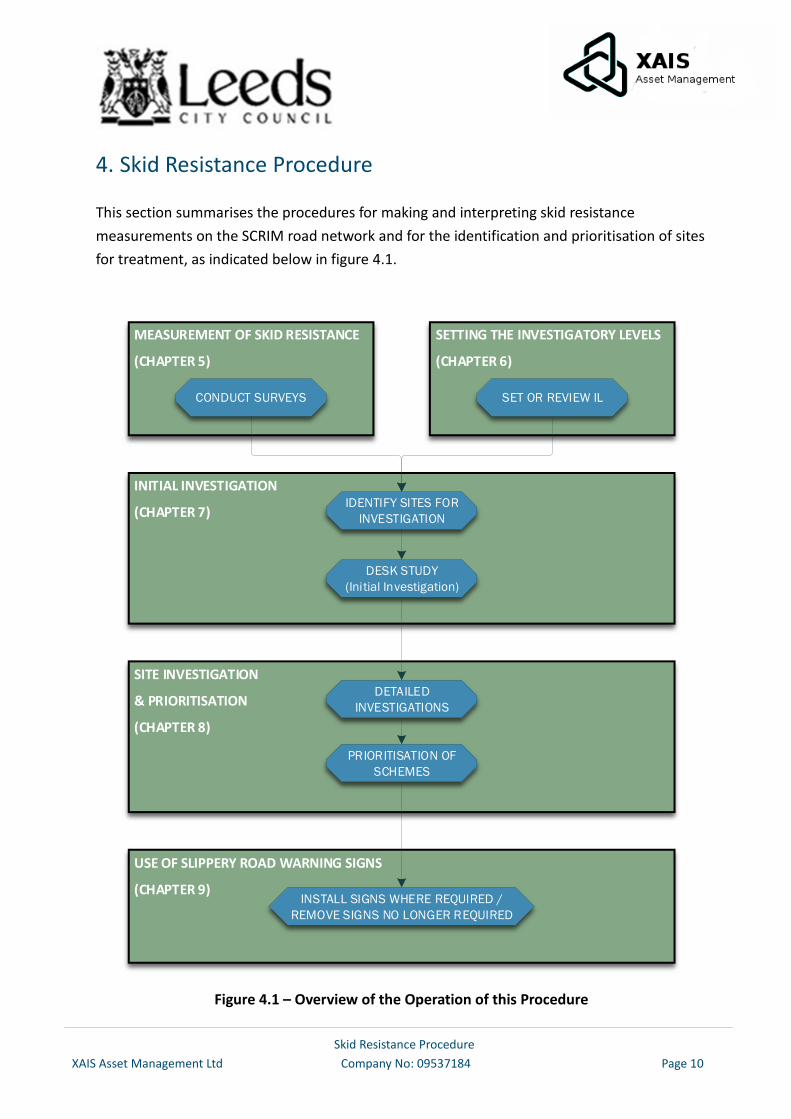
This section summarises the procedures for making and interpreting skid resistance
measurements on the SCRIM road network and for the identification and prioritisation of sites
for treatment, as indicated below in figure 4.1.
MEASUREMENT OF SKID RESISTANCE
(CHAPTER 5)
SETTING THE INVESTIGATORY LEVELS
(CHAPTER 6)
INITIAL INVESTIGATION
(CHAPTER 7)
SET OR REVIEW ILCONDUCT SURVEYS
IDENTIFY SITES FOR
INVESTIGATION
DESK STUDY
(Initial Investigation)
SITE INVESTIGATION
& PRIORITISATION
(CHAPTER 8)
DETAILED
INVESTIGATIONS
PRIORITISATION OF
SCHEMES
USE OF SLIPPERY ROAD WARNING SIGNS
(CHAPTER 9)INSTALL SIGNS WHERE REQUIRED /
REMOVE SIGNS NO LONGER REQUIRED
Figure 4.1 – Overview of the Operation of this Procedure
Skid Resistance Procedure
XAIS Asset Management Ltd Company No: 09537184 Page 11
Routine measurement of skid resistance shall be measured by employing a SCRIM survey as
appropriate and processed to derive a Characteristic SCRIM Coefficient (CSC) in accordance with
chapter 5.
The CSC is an estimate of the underlying skid resistance once the effect of seasonal variation
has been taken into account. This value is taken to represent the state of polish of the road
surface. These terms are explained in Chapter 5 and Appendix 1.
On receipt of processed survey data, the CSC values shall be compared with the predetermined
Investigatory Levels (ILs), to identify lengths of road where the skid resistance is at or below the
Investigatory Level.
Investigatory Levels represent a limit, above which the skid resistance is considered to be
satisfactory at or below which the road is judged to require an investigation of the skid
resistance requirements. Site Categories are assigned based on broad features of the road type
and geometry plus specific features of the individual site. Investigatory Levels are assigned
according to the perceived level of risk within each Site Category. Investigatory Levels will be
reviewed on a rolling programme, to ensure that changes in the network are identified. local
experience is applied and consistency is achieved. The process for setting Investigatory Levels
and the normal range of Investigatory Levels for each Site Category are described in Chapter 6
and Appendix 5
Wherever the CSC is at or below the assigned Investigatory Level an investigation shall be
carried out to determine whether treatment to improve the skid resistance is required or
whether some other action is required to be reviewed.
The investigation process is described in Chapters 7 and 8. The decision of whether treatment
is necessary is unlikely to be clear-cut, but requires competent engineering judgement taking
into account local experience, the nature of the site, the condition of the road surfacing and the
latest available Department for Transport Road Safety Data.
The processes of setting Investigatory Levels and undertaking investigations are
complementary, since local knowledge and experience gained through conducting detailed
investigations can be used to refine the criteria for setting Investigatory Levels for similar types
of sites within the authority.
The investigation process will result in a number of lengths being recommended for treatment
to improve the skid resistance. The priority for treatment will be established through the
defined process for prioritising maintenance if budget allows for these recommendations.
Skid Resistance Procedure
XAIS Asset Management Ltd Company No: 09537184 Page 12
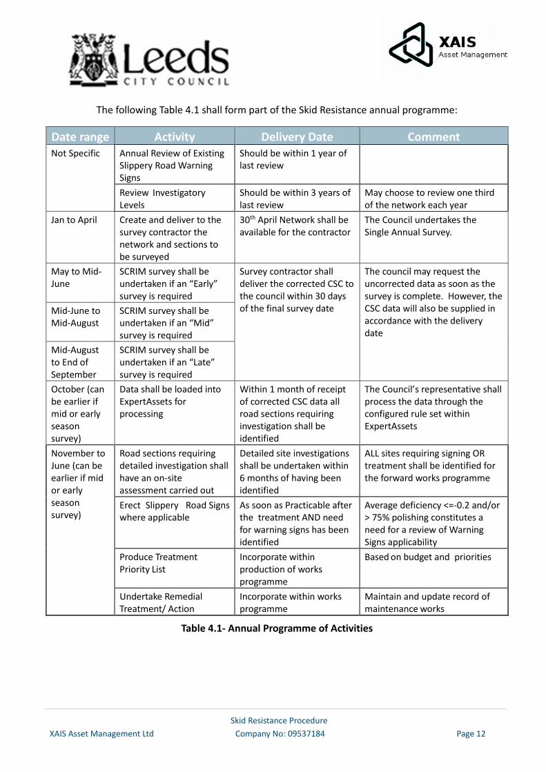
The following Table 4.1 shall form part of the Skid Resistance annual programme:
Date range Activity Delivery Date Comment Not Specific Annual Review of Existing
Slippery Road Warning Signs
Should be within 1 year of last review
Review Investigatory Levels
Should be within 3 years of last review
May choose to review one third of the network each year
Jan to April Create and deliver to the survey contractor the network and sections to be surveyed
30th April Network shall be available for the contractor
The Council undertakes the Single Annual Survey.
May to Mid-June
SCRIM survey shall be undertaken if an “Early” survey is required
Survey contractor shall deliver the corrected CSC to the council within 30 days of the final survey date
The council may request the uncorrected data as soon as the survey is complete. However, the CSC data will also be supplied in accordance with the delivery date
Mid-June to Mid-August
SCRIM survey shall be undertaken if an “Mid” survey is required
Mid-August to End of September
SCRIM survey shall be undertaken if an “Late” survey is required
October (can be earlier if mid or early season survey)
Data shall be loaded into ExpertAssets for processing
Within 1 month of receipt of corrected CSC data all road sections requiring investigation shall be identified
The Council’s representative shall process the data through the configured rule set within ExpertAssets
November to June (can be earlier if mid or early season survey)
Road sections requiring detailed investigation shall have an on-site assessment carried out
Detailed site investigations shall be undertaken within 6 months of having been identified
ALL sites requiring signing OR treatment shall be identified for the forward works programme
Erect Slippery Road Signs where applicable
As soon as Practicable after the treatment AND need for warning signs has been identified
Average deficiency <=-0.2 and/or > 75% polishing constitutes a need for a review of Warning Signs applicability
Produce Treatment Priority List
Incorporate within production of works programme
Based on budget and priorities
Undertake Remedial Treatment/ Action
Incorporate within works programme
Maintain and update record of maintenance works
Table 4.1- Annual Programme of Activities
Skid Resistance Procedure
XAIS Asset Management Ltd Company No: 09537184 Page 13
5. Measurement of Skid Resistance
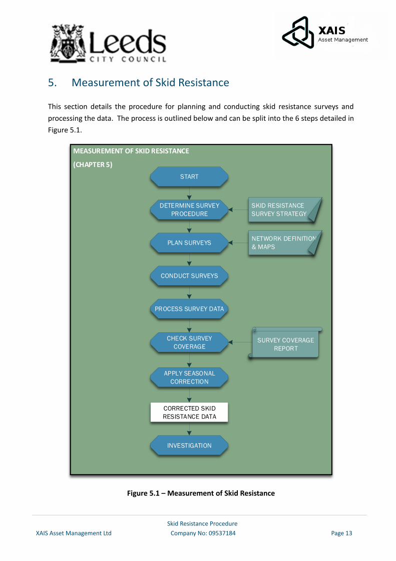
This section details the procedure for planning and conducting skid resistance surveys and
processing the data. The process is outlined below and can be split into the 6 steps detailed in
Figure 5.1.
MEASUREMENT OF SKID RESISTANCE
(CHAPTER 5)
START
DETERMINE SURVEY
PROCEDURE
PLAN SURVEYS
CONDUCT SURVEYS
PROCESS SURVEY DATA
CORRECTED SKID
RESISTANCE DATA
APPLY SEASONAL
CORRECTION
CHECK SURVEY
COVERAGE
INVESTIGATION
SURVEY COVERAGE
REPORT
SKID RESISTANCE
SURVEY STRATEGY
NETWORK DEFINITION
& MAPS
Figure 5.1 – Measurement of Skid Resistance
Skid Resistance Procedure
XAIS Asset Management Ltd Company No: 09537184 Page 14
5.1. Determine the Survey Procedure
The skid resistance of road surfaces can fluctuate within a year and between successive years,
while maintaining a similar general level over a long period of time. By smoothing these
fluctuations due to seasonal effects, sites exhibiting lower skid resistance can be identified more
accurately.
The basis of this Standard is that the overall (summer) level of skid resistance will be assessed
rather than using a single measurement. This overall level of skid resistance is known as the
Characteristic SCRIM Coefficient (CSC).
The Council has adopted the Single Annual Skid Survey. The method is detailed in Appendix 2
and in line with HD28/15 Annex 2. This will produce a CSC for each 10m sub-section of the
surveyed roads.
Skid resistance is not a constant and is influenced by various factors such as test speed,
temperature, weather conditions and also longer-term effects such as seasonal weather
variations or change of traffic flows. With this in mind the measurements of road skid resistance
shall be carried out annually between the dates of 1st May - 30th September.
5.2. Plan Surveys
The SCRIM network which will be subject to skid resistance testing is detailed in Appendix 3 and
is subject to modification if there are changes in crash patterns or amendments to the network.
Following the release of the new Code of Practice for Well-Managed Highway Infrastructure
whereby Authorities are encouraged to adopt a new ‘maintenance hierarchy’ the Council will
review the existing hierarchy and the SCRIM survey shall be carried out on ‘maintenance
hierarchies’ in the future. ‘Maintenance hierarchies’ will be subject to review and are likely to
change and be updated. This will also reflect the ILs which relate to the changes.
An up to date network section list will be provided for the survey contractor to use. Both
directions of each carriageway shall be surveyed, with lane 1 and lane 2 surveyed on dual
carriageways or other multiple lanes defined within the sections held on the Pavement
Management System.
The survey contractor will supply a list of road sections that are excluded from the survey with
a reason for this exclusion, which will be reported back to the Council. Reasons for exclusions
could include traffic calming schemes, speed humps and tables, width, height or weight
restrictions, 20mph zones or road layouts where it is not possible or safe to maintain the survey
speed; this is detailed in Appendix 3.
Skid Resistance Procedure
XAIS Asset Management Ltd Company No: 09537184 Page 15
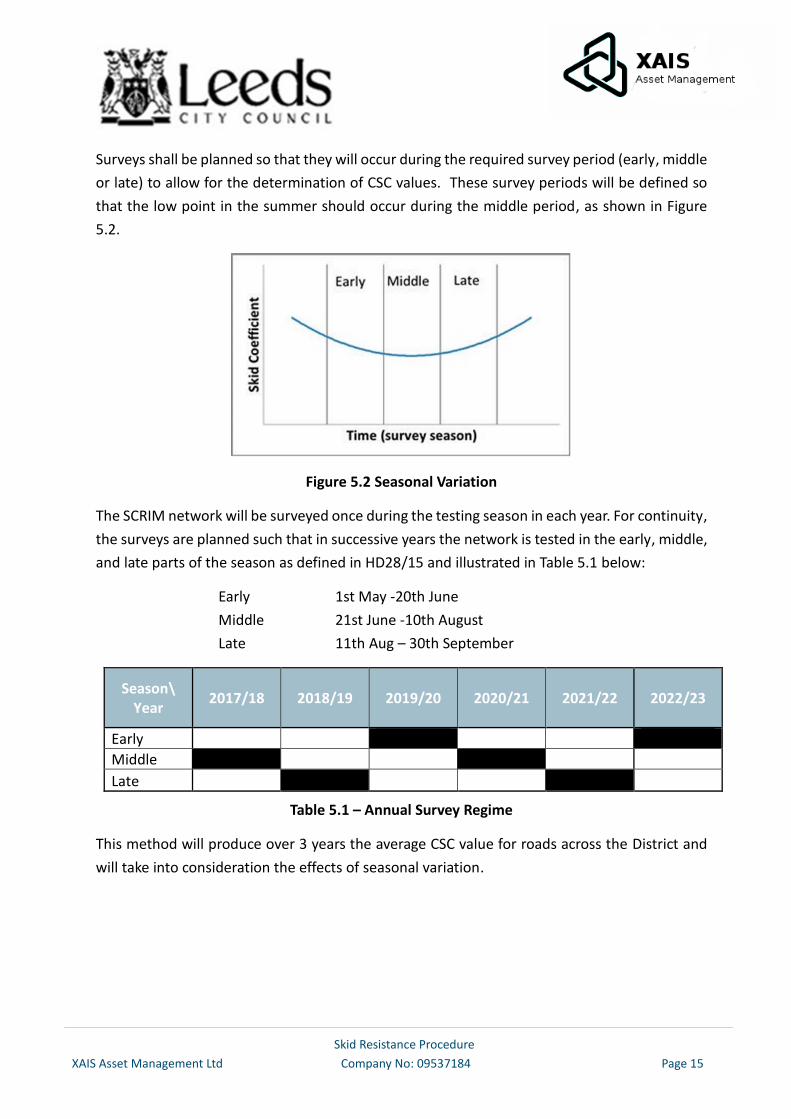
Surveys shall be planned so that they will occur during the required survey period (early, middle
or late) to allow for the determination of CSC values. These survey periods will be defined so
that the low point in the summer should occur during the middle period, as shown in Figure
5.2.
Figure 5.2 Seasonal Variation
The SCRIM network will be surveyed once during the testing season in each year. For continuity,
the surveys are planned such that in successive years the network is tested in the early, middle,
and late parts of the season as defined in HD28/15 and illustrated in Table 5.1 below:
Early 1st May -20th June
Middle 21st June -10th August
Late 11th Aug – 30th September
Season\ Year
2017/18 2018/19 2019/20 2020/21 2021/22
2022/23
Early
Middle
Late
Table 5.1 – Annual Survey Regime
This method will produce over 3 years the average CSC value for roads across the District and
will take into consideration the effects of seasonal variation.
Skid Resistance Procedure
XAIS Asset Management Ltd Company No: 09537184 Page 16
5.3. Conduct Surveys
Measurements shall be carried out with the test wheel in the nearside (left) wheel path of the
lane to be tested.
If it is necessary for the machine to deviate from the test line (e.g. to avoid a physical obstruction
or surface contamination) the data shall be marked as invalid and eliminated from the standard
analysis procedure.
Roundabouts can present practical problems regarding potential traffic conflicts and testing
speed. They range from small, mini-roundabouts to large grade-separated interchanges. Larger
roundabouts may have free-flowing traffic or traffic light controls at certain times of day.
After entering a roundabout, a minimum of one complete circuit shall be tested. Where safe to
do so, the preferred test line is the outermost lane. However, on multiple lane roundabouts
with lane markings for different routes, it may be necessary to test an alternative lane to avoid
conflict with other traffic.
A roundabout which cannot be surveyed is one where the survey speed of 50km/h cannot be
safely maintained. These include mini roundabouts and small island roundabouts that are
physically too small to test as above. These shall be tested as part of the main carriageway and
do not need to be tested separately.
Measurements shall not be undertaken where the air temperature is below 5°C.
Testing shall be avoided in heavy rainfall or where there is standing water on the road surface.
Excess water on the surface can affect the drag forces at the tyre/road interface and influence
the measurements.
The target survey speed shall be 50km/h where this speed is permissible given the mandatory
speed limit in force. The machine driver shall maintain a vehicle speed as close to the target
test speed as possible. However, all speed limits, either temporary or permanent, must be
obeyed regardless of the target survey speed. In addition, if it is not safe to maintain the target
speed then a different speed may be used at the discretion of the driver. The safety of the
machine and other road users shall take priority at all times.
Contamination of the road surface by mud, oil, grit, or other contaminants shall be noted and
the results eliminated from the standard analysis procedure.
The survey operator shall maintain a record of weather conditions that could influence the
survey results, such as heavy rainfall and strong wind.
Skid Resistance Procedure
XAIS Asset Management Ltd Company No: 09537184 Page 17
5.4. Pre-Process Survey Data
Readings for each 10m sub-section collected within the speed range 25 to 85km/h shall be
corrected to a speed of 50km/h using the following equation:
SR(50) = SR(s)*(-0.0152*s2 +4.77 *s +799)/1000
where:
SR(50) is the value of SR(s) corrected to 50km/h
SR(s) is the Sideway Force Coefficient, measured at test speeds, multiplied by 100. This term is
defined further in British Standard BS7941-1.
Temperature correction shall not be applied for surveys carried out under the conditions set in
this standard.
SC values shall be calculated for each 10m sub-section for which a valid SR(s) value is available
using the following equation:
SC = (SR(50) /100) * Index of SFC
where:
The Index of SFC (Sideway Force Coefficient) is currently 0.78 and shall be applied to all survey
machines in current use.
5.5. Check Survey Coverage
The survey contractor shall produce a survey coverage report detailing the network that was to
be surveyed, lengths with missing or invalid data. An explanation for the missing or invalid data
will be submitted with the survey data.
5.6. Apply Seasonal Correction
Once the data has been loaded and checked the seasonally corrected CSC values shall be
determined from the SC values following the method described in Appendix 2 (Annex 2 of
HD28/15).
Skid Resistance Procedure
XAIS Asset Management Ltd Company No: 09537184 Page 18
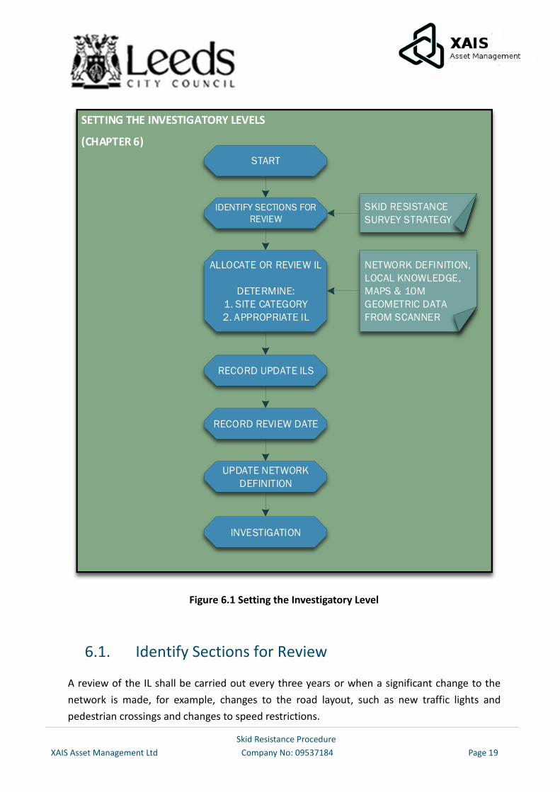
6. Setting the Investigatory Level
An Investigatory Level (IL) shall be defined for every part of the SCRIM network, by determining
which Site Category is most appropriate to each location and then selecting an appropriate IL
from within the range for that Site Category. The objective of setting an IL is to assign a level of
skid resistance appropriate for the risk on the site, at or below which further investigation is
required to evaluate the site-specific risks in more detail.
In developing this procedure reference has been made to skidding resistance standard HD28/15
developed for Highways England. The site categories and associated Investigatory Levels
defined in HD28/15 have been developed for the UK strategic road network (Trunk Roads and
Motorways). Therefore, in formulating this procedure, it has been recognized that these
standards may not be applicable to the more diverse nature of local authority roads. A table of
approved Investigatory Levels is contained in Table 6.1. A schedule detailing the rationale for
the Investigatory Levels and variations from HD 28/15 can be found in Appendix 5.
The process is outlined below and can be split into the 3 steps detailed in Figure 6.1.
Skid Resistance Procedure
XAIS Asset Management Ltd Company No: 09537184 Page 19
SETTING THE INVESTIGATORY LEVELS
(CHAPTER 6)
START
IDENTIFY SECTIONS FOR
REVIEW
ALLOCATE OR REVIEW IL
DETERMINE:
1. SITE CATEGORY
2. APPROPRIATE IL
RECORD UPDATE ILS
UPDATE NETWORK
DEFINITION
RECORD REVIEW DATE
INVESTIGATION
SKID RESISTANCE
SURVEY STRATEGY
NETWORK DEFINITION,
LOCAL KNOWLEDGE,
MAPS & 10M
GEOMETRIC DATA
FROM SCANNER
Figure 6.1 Setting the Investigatory Level
6.1. Identify Sections for Review
A review of the IL shall be carried out every three years or when a significant change to the
network is made, for example, changes to the road layout, such as new traffic lights and
pedestrian crossings and changes to speed restrictions.
Skid Resistance Procedure
XAIS Asset Management Ltd Company No: 09537184 Page 20
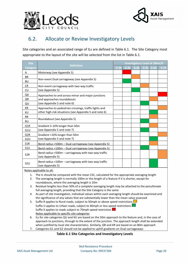
6.2. Allocate or Review Investigatory Levels
Site categories and an associated range of ILs are defined in Table 6.1. The Site Category most
appropriate to the layout of the site will be selected from the list in Table 6.1.
Site
Category Definition
Investigatory Level at 50km/h
0.30 0.35 0.40 0.45 0.50 0.55
A Motorway (see Appendix 5)
BR Non-event Dual carriageway (see Appendix 5)
BU
CR Non-event carriageway with two-way traffic (see Appendix 5)
CU
QX Approaches to and across minor and major junctions and approaches roundabouts
(see Appendix 5 and note 6)
QR
QU
KR Approaches to pedestrian crossings, traffic lights and other high-risk situations (see Appendix 5 and note 6)
KU
RR
Roundabout (see Appendix 5)
RU
G1R Gradient 5-10% longer than 50m (see Appendix 5 and note 7)
G1U
G2R Gradient >10% longer than 50m (see Appendix 5 and note 7)
G2U
S1R Bend radius <500m – Dual carriageway (see Appendix 5)
S1U Bend radius <100m – Dual carriageway (see Appendix 5)
S2R Bend radius <500m – carriageway with two-way traffic (see Appendix 5)
S2U Bend radius <100m – carriageway with two-way traffic (see Appendix 5)
Notes applicable to all:
1. The IL should be compared with the mean CSC, calculated for the appropriate averaging length 2. The averaging length is normally 100m or the length of a feature if it is shorter, except for
roundabouts, where the averaging length is 10m 3. Residual lengths less than 50% of a complete averaging length may be attached to the penultimate
full averaging length, providing that the Site Category is the same 4. As part of site investigation, individual values within each averaging length should be examined and
the significance of any values that are substantially lower than the mean value assessed 5. Suffix R applies to Rural roads, subject to 50mph or above speed restrictions
Suffix U applies to Urban roads, subject to 40mph or less speed restrictions Suffix X applies to roads subject to 70mph speed restriction Notes applicable to specific site categories
6. ILs for site categories QU and KU are based on the 50m approach to the feature and, in the case of approach to junctions, through to the extent of the junction. The approach length shall be extended when justified by local site characteristics. Similarly, QR and KR are based on an 80m approach
7. Categories G1 and G2 should not be applied to uphill gradients on Dual carriageways
Table 6.1 Site Categories and Investigatory Levels
Skid Resistance Procedure
XAIS Asset Management Ltd Company No: 09537184 Page 21
After selecting a Site Category, the appropriate IL is assigned.
If more than one Site Category is appropriate, then the Site Category with the highest
recommended IL will be selected. If the highest recommended IL for the site categories are the
same, then the category highest up the Table shall be selected (A being the highest on the table
and S2 the lowest). When defining site categories, no site shall be defined as being less than
50% of its averaging length. Where this occurs, the site should be included in either the
preceding or following site, whichever has an IL nearest to and at or above the investigatory
level of the site being defined.
6.3. Record Updated Investigatory Levels and Review Date
The sections reviewed shall be recorded, together with the review date and any changes to the
site categories and ILs that may be reviewed.
Skid Resistance Procedure
XAIS Asset Management Ltd Company No: 09537184 Page 22
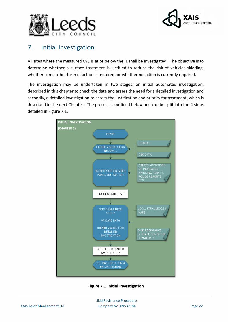
7. Initial Investigation
All sites where the measured CSC is at or below the IL shall be investigated. The objective is to
determine whether a surface treatment is justified to reduce the risk of vehicles skidding,
whether some other form of action is required, or whether no action is currently required.
The investigation may be undertaken in two stages: an initial automated investigation,
described in this chapter to check the data and assess the need for a detailed investigation and
secondly, a detailed investigation to assess the justification and priority for treatment, which is
described in the next Chapter. The process is outlined below and can be split into the 4 steps
detailed in Figure 7.1.
INITIAL INVESTIGATION
(CHAPTER 7)
START
IDENTIFY SITES AT OR
BELOW IL
IDENTIFY OTHER SITES
FOR INVESTIGATION
PRODUCE SITE LIST
PERFORM A DESK
STUDY
VAIDATE DATA
IDENTIFY SITES FOR
DETAILED
INVESTIGATION
SITE INVESTIGATION &
PRIORITISATION
IL DATA
CSC DATA
OTHER INDICATIONS
OF INCREASED
SKIDDING RISK I.E.
POLICE REPORTS
ETC.
LOCAL KNOWLEDGE &
MAPS
SKID RESISTANCE,
SURFACE CONDITION &
CRASH DATA
SITES FOR DETAILED
INVESTIGATION
Figure 7.1 Initial Investigation
Skid Resistance Procedure
XAIS Asset Management Ltd Company No: 09537184 Page 23
7.1. Identify Sites at or below the Investigatory Level
The mean CSC for 100m averaging lengths should be calculated for comparison with the IL,
except that 10m averaging lengths should be analysed for roundabouts (Site Category R). The
averaging length shall be truncated on any change of Site Category or IL; consequently, the
averaging length will be shorter where the Site Category is less than 100m long or at the end of
a Site Category longer than 100m. Residual lengths less than 50% of a complete averaging length
will be appended to the penultimate length, if both the lengths have the same IL. Therefore,
site lengths will range from 50-149m in length (except for roundabouts).
7.2. Identify Other Sites Requiring Investigation
An investigation shall also be carried out if, as a result of processes separate from this
procedure, sites are identified where increased wet or skidding crash levels have been
observed. Examples include Annual Safety Reports, Police complaints, local observations and
damage to roadside furniture. These sites shall be subject to a detailed investigation.
7.3. Data Validation
Basic data validation checks shall be conducted for sites that have been identified as at or below
the IL. This shall include confirming that the IL has been assigned correctly in accordance with
current guidance and that the skid resistance recorded is within the normal range expected.
If the IL is incorrect then it shall be updated and recorded together with the date of the change.
If the skid resistance is above the revised IL, then further investigation is unnecessary and the
change of IL should be recorded as the outcome of the investigation.
7.4. Identify Sites for Detailed Investigation
Sites at or below IL requiring detailed investigation should be identified based on the Site
Category, IL, current skid resistance and observed crash history.
A list of sites requiring detailed investigation shall be produced using ExpertAssets© within 1
month of receipt of the CSC data.
The identification of sites requiring detailed investigation (the initial site score) can be carried
out as detailed in Appendix 6, which is based on the alternative method detailed in Annex 7 of
HD28/15. (The alternative method is an alternative to the crash model, which has been
developed specifically for the Highways England road network. It is not appropriate to use this
crash model on a network outside of the Highways England network).
Skid Resistance Procedure
XAIS Asset Management Ltd Company No: 09537184 Page 24
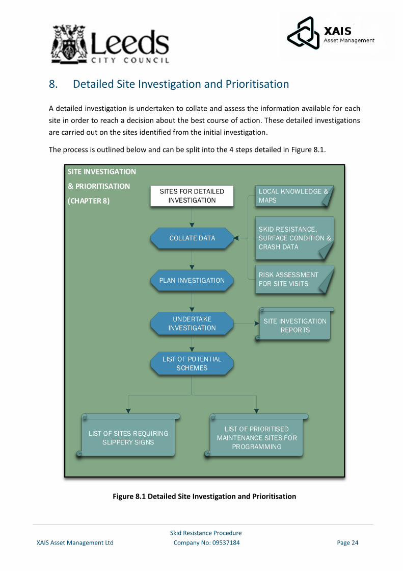
8. Detailed Site Investigation and Prioritisation
A detailed investigation is undertaken to collate and assess the information available for each
site in order to reach a decision about the best course of action. These detailed investigations
are carried out on the sites identified from the initial investigation.
The process is outlined below and can be split into the 4 steps detailed in Figure 8.1.
SITE INVESTIGATION
& PRIORITISATION
(CHAPTER 8)
COLLATE DATA
PLAN INVESTIGATION
LOCAL KNOWLEDGE &
MAPS
RISK ASSESSMENT
FOR SITE VISITS
SITES FOR DETAILED
INVESTIGATION
SKID RESISTANCE,
SURFACE CONDITION &
CRASH DATA
UNDERTAKE
INVESTIGATIONSITE INVESTIGATION
REPORTS
LIST OF POTENTIAL
SCHEMES
LIST OF SITES REQUIRING
SLIPPERY SIGNS
LIST OF PRIORITISED
MAINTENANCE SITES FOR
PROGRAMMING
Figure 8.1 Detailed Site Investigation and Prioritisation
Skid Resistance Procedure
XAIS Asset Management Ltd Company No: 09537184 Page 25
8.1. Collate Data
As a minimum, the data collected shall include skid resistance, texture depth and the latest
available Department for Transport Road Safety Data.
Skid resistance data at 10m intervals for bends and roundabouts shall be obtained, because
short lengths with low skid resistance could be hazardous for vehicles cornering. These shall
not be disguised by being averaged over a longer length.
Skid resistance data at 10m intervals shall also be obtained if the condition of the surfacing
material is known to be variable over local areas.
The SCANNER defects of rut depth, longitudinal profile, gradient, cross-fall and curvature data
should be reviewed to establish if they are relevant. i.e. if the site has poor transverse or
longitudinal evenness, or bends or gradients. In some instances, these data assist in checking
whether the Site Category and/or Investigatory Level are correct or need amending.
Information on the date of last surface treatment if available may also be relevant to the
investigation and the interpretation of collision data.
For each site, the relevant data should be collated to show the location of lengths with poor
surface condition relative to the location of previous crashes and features such as bends,
junctions, etc. This data will be collated as strip diagrams and GIS mapping.
The location of crashes occurring in wet conditions, irrespective of whether skidding was
reported, should be identified specifically where possible.
The latest available crash data is supplied nationally and is updated on an annual basis. (2015
crash data became available in July 2016). The data set can be downloaded from the following
web address: https://data.gov.uk/dataset/road-accidents-safety-data
Given the limited accuracy of locating crash positions, it may be assumed for the purpose of
this investigation that the position of a crash coincides with a Site if it occurred within 75m for
urban roads (40 mph or less) and 200m for rural roads (50mph or greater). However, crashes in
excess of 75m/200m can be ‘tagged’ to the site and crashes within the 75m/200m boundary
can be ‘untagged’ if their location is deemed to not be relevant to the specific site. For example,
there are some crashes that are within 75m of a site that occur on roads parallel to the site but
cannot be accessed from the site.
Note: HD28/15 states a 200m buffer, but after reviewing the accuracy of the location of crashes,
particularly in urban areas, it was deemed more appropriate to set a buffer of 75m for urban
roads (40mph or less); the rationale for 75m is that the stopping distance for 40 mph in the wet
Skid Resistance Procedure
XAIS Asset Management Ltd Company No: 09537184 Page 26
is 72m (75m accommodates a further 3m for location accuracy). Far too many crashes
automatically tagged were clearly not relevant to the site as there were on parallel roads, etc.
The overall crash risk shall be calculated for the site for comparison with control data.
8.2. Plan Investigations
Investigations should be planned primarily to maximize efficiency. Greater priority should be
given to completing investigations for sites that are substantially below the IL or where the crash
history indicates that there is a risk of wet skidding crashes occurring.
All site visits will be undertaken by appropriately qualified personnel and wherever possible
undertaken on foot.
The following methods/information/media can be used to supplement the information collated
by the site visit:
A driven site visit, often undertaken immediately before and/or after the on-foot site
inspection (this allows the pattern of traffic movement and speed to be observed during
the visit, but has associated safety risks that shall be controlled).
Recent local knowledge of the site (this may provide a more general knowledge of the
road usage under a wider range of traffic, weather and lighting conditions).
Video records and maps. Note: maps should not be used in isolation as they do not show
obstructions to visibility, drainage issues, field accesses, hidden dips etc.
8.3. Undertake Investigations
Detailed site investigations shall be undertaken within 6 months of having been identified.
Site investigations shall consider the factors detailed below and shall be carried out by
personnel with suitable experience and/or qualifications. An example template of a site
investigation form is given in Appendix 8.
The level of detail appropriate for this investigation will depend on the nature of the site and
the time since a detailed investigation was last carried out. Many of the points listed are only
relevant to more complex sites. If the site has been investigated recently, then it will only be
necessary to identify the changes that have occurred since the last investigation was carried
out.
The full carriageway width should be included in the investigation. e.g. all lanes of a dual
carriageway and both directions of a single carriageway. In addition, all junction approaches
Skid Resistance Procedure
XAIS Asset Management Ltd Company No: 09537184 Page 27
should also be investigated to determine whether the advance signing/alignment etc. is
adequate or could be improved.
When carrying out site investigations it should be borne in mind that skid resistance and texture
depth are generally measured in the nearside wheel track. If, during a site investigation, the
rest of the pavement is not visually consistent then it is possible that the skid resistance of the
rest of the lane or other lanes could be lower than the line tested. In these cases, it may be
necessary to carry out additional surveys to investigate this or duplicate this survey to confirm
the findings.
If a site contains a sharp bend to the left in combination with traffic braking or accelerating,
then the offside wheel path can become more polished and the CSC can be up to 0.05 units
lower than in the nearside wheel path. If present, this should be taken into account during the
detailed investigation.
Determine if the skid resistance is likely to be representative for the site; in particular, very low
values should be viewed with caution. Localised reduction in the skid resistance can be caused
by contamination or by fatting up of the binder. Alternatively, it is possible that there has been
an error in the survey. In this case, the data should be compared to data measured in previous
years and also with adjacent lengths with the same surfacing material, to determine if the skid
resistance is representative of the condition of the surfacing material. If it is considered that
the reduction in skid resistance is temporary and not representative for the site, then this should
be recorded with reasons. Further investigation is not needed at that time, but if subsequent
surveys continue to appear unrepresentative then the causes should be investigated.
As a result of the investigation, a clear recommendation shall be recorded of the actions to be
taken (including if no immediate action is required).
If the site investigation identified any characteristic of the site or road user behaviour that
suggests other road safety engineering measures could be appropriate, then persons with
relevant local experience, such as the person locally responsible for crash investigation and
prevention, should be consulted.
If the site investigation identifies requirements for additional routine highway maintenance,
such as sweeping, renewal of markings etc. then appropriate action shall be taken.
Treatment to improve the skid resistance should be recommended if, taking into account the
nature of the site and the observed crash history, it is likely to reduce the risk of crashes in wet
conditions. Based on knowledge of skid resistance and crash risk trends, this includes locations
where the position of crashes in wet conditions (whether or not skidding was reported) appears
Skid Resistance Procedure
XAIS Asset Management Ltd Company No: 09537184 Page 28
to be linked to surface condition, or where the overall crash risk is higher than average when
compared with suitable control data.
If treatment is only required on part of the site, then particular care should be taken to identify
the lengths where treatment is required, this should be reviewed by an engineer on site to
confirm these areas / limits.
Treatment should also be recommended if the skid resistance, combined with the nature of the
individual site, suggest that the observed crash count underestimates the actual level of risk. In
this case, preventive treatment is justified to pre-empt a potential increase in crashes.
If there is no justification for treatment, then no further action shall be required.
The results of the investigation shall be documented and retained together with the identity of
the assessor and other parties consulted.
8.4. Prioritise and Programme Maintenance
Budgeting and programming issues will influence when the treatments are carried out and this
process should be managed through the Council’s process for prioritising maintenance.
Ranking of skid resistance maintenance schemes takes into account the findings of the site
investigations which include:
Average Deficiency
Wet Skid Crashes
On site questions as detailed in Appendix 7 (Table A.7.2)
The most appropriate form of treatment will be identified for each site which is found to require
remedial works and to restore an adequate level of skid resistance. Often this will include a
surface treatment. However, if site investigations should identify different defects or an issue
with the behaviour of road users which an engineering measure may be able to resolve, then
the relevant department within the council will be notified to identify the best course of action
to be taken.
WYCA+ has produced a risk based methodology for the identification and prioritisation of
proposed treatments and actions as detailed in Appendix 7. This provides an auditable
objective process to the identification and prioritisation based on the results from the detailed
on-site investigations and other available information.
Skid Resistance Procedure
XAIS Asset Management Ltd Company No: 09537184 Page 29
The final programme of works will be based on the available budget and Council priorities. The
final list of schemes shall be reported in accordance with the procedures detailed in the
Highways Infrastructure Asset Management Policy.
Skid Resistance Procedure
XAIS Asset Management Ltd Company No: 09537184 Page 30
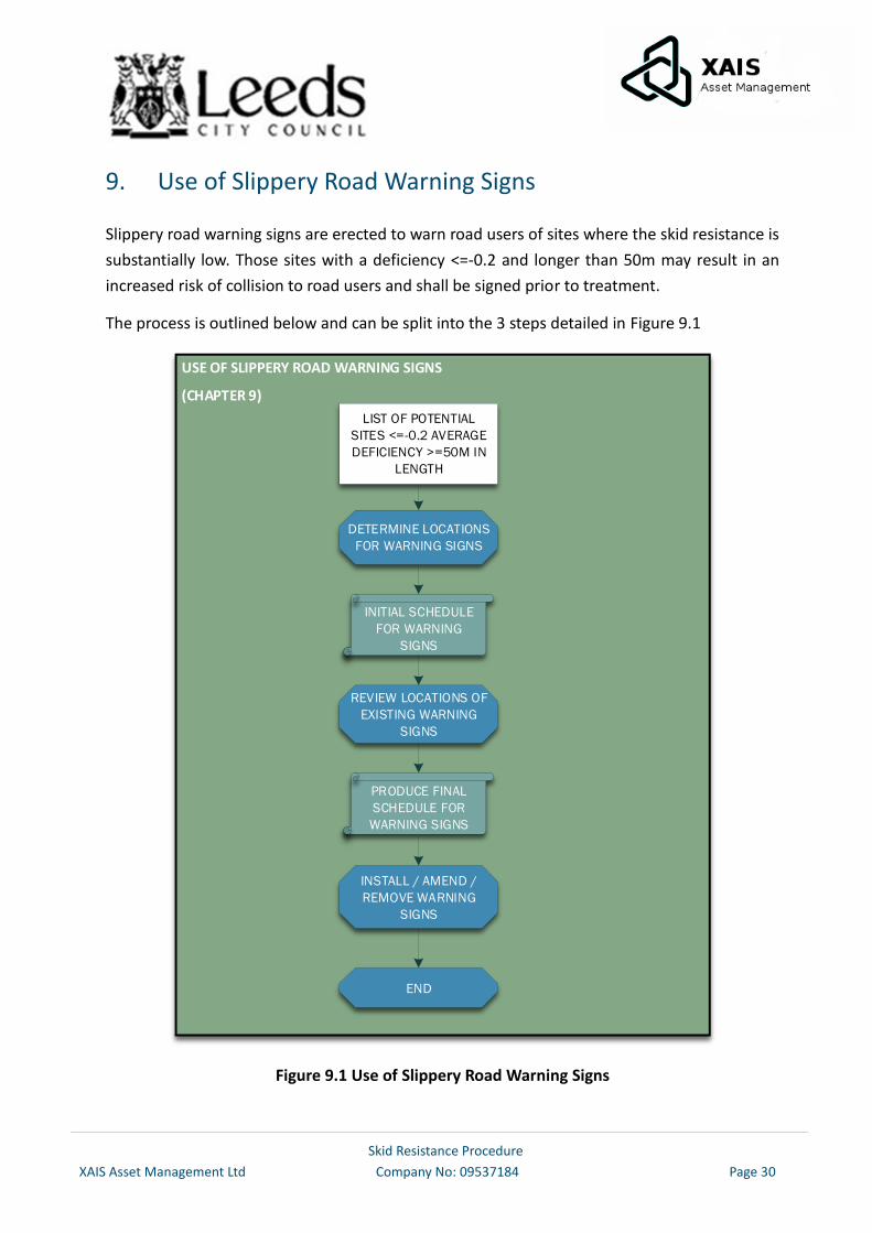
9. Use of Slippery Road Warning Signs
Slippery road warning signs are erected to warn road users of sites where the skid resistance is
substantially low. Those sites with a deficiency <=-0.2 and longer than 50m may result in an
increased risk of collision to road users and shall be signed prior to treatment.
The process is outlined below and can be split into the 3 steps detailed in Figure 9.1
USE OF SLIPPERY ROAD WARNING SIGNS
(CHAPTER 9)
DETERMINE LOCATIONS
FOR WARNING SIGNS
LIST OF POTENTIAL
SITES <=-0.2 AVERAGE
DEFICIENCY >=50M IN
LENGTH
REVIEW LOCATIONS OF
EXISTING WARNING
SIGNS
INITIAL SCHEDULE
FOR WARNING
SIGNS
INSTALL / AMEND /
REMOVE WARNING
SIGNS
PRODUCE FINAL
SCHEDULE FOR
WARNING SIGNS
END
Figure 9.1 Use of Slippery Road Warning Signs
Skid Resistance Procedure
XAIS Asset Management Ltd Company No: 09537184 Page 31
9.1. Determine Locations Requiring Warning Signs
Sites which have been identified as requiring treatment to improve the skid resistance shall have
‘slippery road’ warning signs erected where it is deemed appropriate. Such signs will not
automatically be used on every scheme only to advise the road users where an engineer has
reviewed all the information available to them.
‘Slippery road’ warning signs shall not be used in connection with newly-laid asphalt road
surfacing materials see Appendix 1 “Early life skid resistance of asphalt surfacing” (HD28/15
Annex 1. A.1.24 to A.1.26).
Once the location of sites requiring warning signs has been identified, a schedule for warning
signs shall be produced.
9.2. Review Locations of Existing Signs
The skid resistance at the location of all existing slippery road warning signs shall be reviewed
to determine whether the sign is still needed. This review should occur annually and once
completed the schedule for warning signs shall be updated to include the signs which require
removal.
9.3. Install/ Amend/ Remove Warning Signs
Warning signs shall be installed as soon as practicable after the need for treatment has been
identified, on sites which have an average deficiency <=-0.2. They shall then be removed as
soon as practical after treatment has been applied.
The ‘slippery road’ warning sign (Diagram 557) in conjunction with an appropriate
supplementary plate (Diagram 570) must be used in accordance with the Traffic Signs
Regulations and General Directions and Chapter 4 of the Traffic Signs Manual.
Short individual lengths requiring warning signs should be merged if they are separated by less
than 1km.
For the purpose of legal proceedings, it is essential that records of the erection and removal of
slippery road warning signs shall be kept, including works orders issued and inventories.
A visual inspection of the site shall be made after the signs are erected to confirm that they
have been erected and correctly placed and a record of this observation shall be made and
retained.
Skid Resistance Procedure
XAIS Asset Management Ltd Company No: 09537184 Page 32
10. Records
In order to maintain accurate and up to date information it will be necessary to formally record
skid resistance data and this will be done as follows:
All verbal and written enquiries regarding skidding matters on the surveyed network will be
registered onto a customer enquiry system.
The following records shall be maintained to demonstrate the ongoing operation of this
procedure:
Investigatory Levels for the surveyed road network, including justification for any
deviation from the recommendations of HD28/15
Skid testing results and data analysis
Site investigation findings for sites assessed
A record of sites where and when slippery road warning signs have been erected
showing subsequent removal dates where appropriate
Priority lists of sites for remedial treatment to restore an adequate level of skid
resistance
Details of completed works programs, relating to remedial treatment for substandard
skid resistance
Skid Resistance Procedure
XAIS Asset Management Ltd Company No: 09537184 Page 33
11. References
County Surveyors Society – Code of Practice for Highways Management – Section 9.7
Skidding Resistance Measurement Requirements (Revision F).
County Surveyors Society – CSS Guidance Note – The Use of High Friction Surfaces
(January 2010).
Design Manual for Roads and Bridges.
HD28 (DMRB 7.3.1) Skid Resistance.
HD29 (DRMB 7.3.2) Data for Pavement Assessments.
HD36 (DMRB 7.5.1) Surfacing Materials for New and Maintenance Construction.
HD37 (DMRB 7.5.2) Bituminous Surfacing Materials and techniques.
Highways Act 1980.
LR738; Hosking, J. R. and Woodford, G. C. Measurement of Skidding Resistance Part ii:
Factors Affecting the Slipperiness of a Road Surface, TRRL, 1976
The Traffic Signs Regulations and General Directions 2016.
TRL Report TRL622 - Accidents and the Skidding Standards for Strategic Roads in
England.
Well-managed Highway Infrastructure: A Code of Practice.
Skid Resistance Procedure
XAIS Asset Management Ltd Company No: 09537184 Page 34
Appendix 1 – Background Information on the Measurement and Interpretation of Skid Resistance for Highways England
Note: This Appendix is a copy of Annex 1 of HD28/15
What is Skid Resistance?
The contribution of the road surface to the overall friction available between the tyre and the
road surface is known as skid resistance. The skid resistance of a wet or damp road surface can
be substantially lower than the same surface when dry, and is more dependent on the condition
of the surfacing. For this reason, measurements of skid resistance for the purpose of routine
condition monitoring are made on wetted road surfaces.
How is it generated?
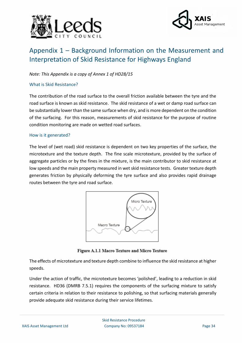
The level of (wet road) skid resistance is dependent on two key properties of the surface, the
microtexture and the texture depth. The fine scale microtexture, provided by the surface of
aggregate particles or by the fines in the mixture, is the main contributor to skid resistance at
low speeds and the main property measured in wet skid resistance tests. Greater texture depth
generates friction by physically deforming the tyre surface and also provides rapid drainage
routes between the tyre and road surface.
The effects of microtexture and texture depth combine to influence the skid resistance at higher
speeds.
Under the action of traffic, the microtexture becomes ‘polished’, leading to a reduction in skid
resistance. HD36 (DMRB 7.5.1) requires the components of the surfacing mixture to satisfy
certain criteria in relation to their resistance to polishing, so that surfacing materials generally
provide adequate skid resistance during their service lifetimes.
Skid Resistance Procedure
XAIS Asset Management Ltd Company No: 09537184 Page 35
Relationship with crash risk
Within normal ranges, low skid resistance does not cause crashes although depending on the
particular circumstances, it may be a significant contributory factor. The level of skid resistance,
even on a polished surface, will generally be adequate to achieve normal acceleration,
deceleration and cornering manoeuvres on sound surfaces that are wet but free from other
contamination. However, higher skid resistance is required to allow manoeuvres that demand
higher friction to be completed safely, e.g. to stop quickly or corner sharply. Higher skid
resistance can therefore reduce crashes in cases where drivers need to complete a more
demanding manoeuvre in order to avoid a crash. A key part of this Standard is the judgement
of locations where this is more likely to occur, so that the provision of higher levels of skid
resistance can be targeted at these locations.
Crash analyses have shown that there are relationships between measured skid resistance and
crash risk. These relationships are not precise, in that differences in skid resistance may account
for only a relatively small part of the difference in crash risk between individual sites because
of all the other factors involved. Nevertheless, they have allowed general conclusions to be
drawn that make it possible to provide guidance for managing the provision of skid resistance
on the network.
The influence of skid resistance on crash risk is markedly different for roads with different
characteristics. For this reason, Site Categories have been defined to group roads with similar
characteristics.
For some Site Categories, no statistically significant relationship, or only a weak relationship is
observed between skid resistance and crash risk. A good example of this is motorways, where
the road design has effectively reduced the potential for conflict between road users. Although
the skid resistance is still important because of the need to provide uniform road characteristics,
the level of skid resistance can be lower than other categories.
For other Site Categories, progressively more crashes are observed on average, as the skid
resistance falls. For these categories, there are benefits in maintaining a higher level of skid
resistance to contribute to reducing the number of crashes at these sites.
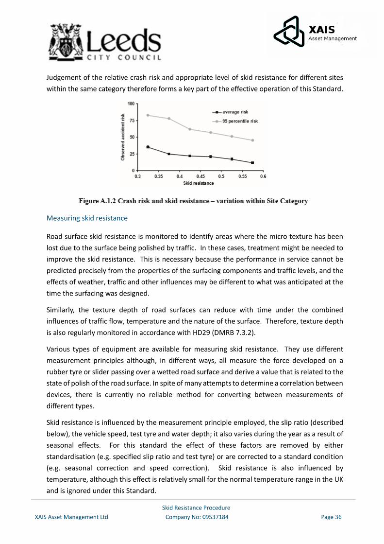
However, not all sites within a single category are equivalent in terms of their crash risk. Figure
A.1.2 illustrates the range in crash risk present for individual sites within a single Site Category.
This range is not surprising when the range of characteristics present within a single nominal
Site Category is considered. e.g. in road design and traffic flow. It should also be noted that
there is no boundary at which the skid resistance passes from being ‘safe’ to being ‘dangerous’.
Skid Resistance Procedure
XAIS Asset Management Ltd Company No: 09537184 Page 36
Judgement of the relative crash risk and appropriate level of skid resistance for different sites
within the same category therefore forms a key part of the effective operation of this Standard.
Measuring skid resistance
Road surface skid resistance is monitored to identify areas where the micro texture has been
lost due to the surface being polished by traffic. In these cases, treatment might be needed to
improve the skid resistance. This is necessary because the performance in service cannot be
predicted precisely from the properties of the surfacing components and traffic levels, and the
effects of weather, traffic and other influences may be different to what was anticipated at the
time the surfacing was designed.
Similarly, the texture depth of road surfaces can reduce with time under the combined
influences of traffic flow, temperature and the nature of the surface. Therefore, texture depth
is also regularly monitored in accordance with HD29 (DMRB 7.3.2).
Various types of equipment are available for measuring skid resistance. They use different
measurement principles although, in different ways, all measure the force developed on a
rubber tyre or slider passing over a wetted road surface and derive a value that is related to the
state of polish of the road surface. In spite of many attempts to determine a correlation between
devices, there is currently no reliable method for converting between measurements of
different types.
Skid resistance is influenced by the measurement principle employed, the slip ratio (described
below), the vehicle speed, test tyre and water depth; it also varies during the year as a result of
seasonal effects. For this standard the effect of these factors are removed by either
standardisation (e.g. specified slip ratio and test tyre) or are corrected to a standard condition
(e.g. seasonal correction and speed correction). Skid resistance is also influenced by
temperature, although this effect is relatively small for the normal temperature range in the UK
and is ignored under this Standard.
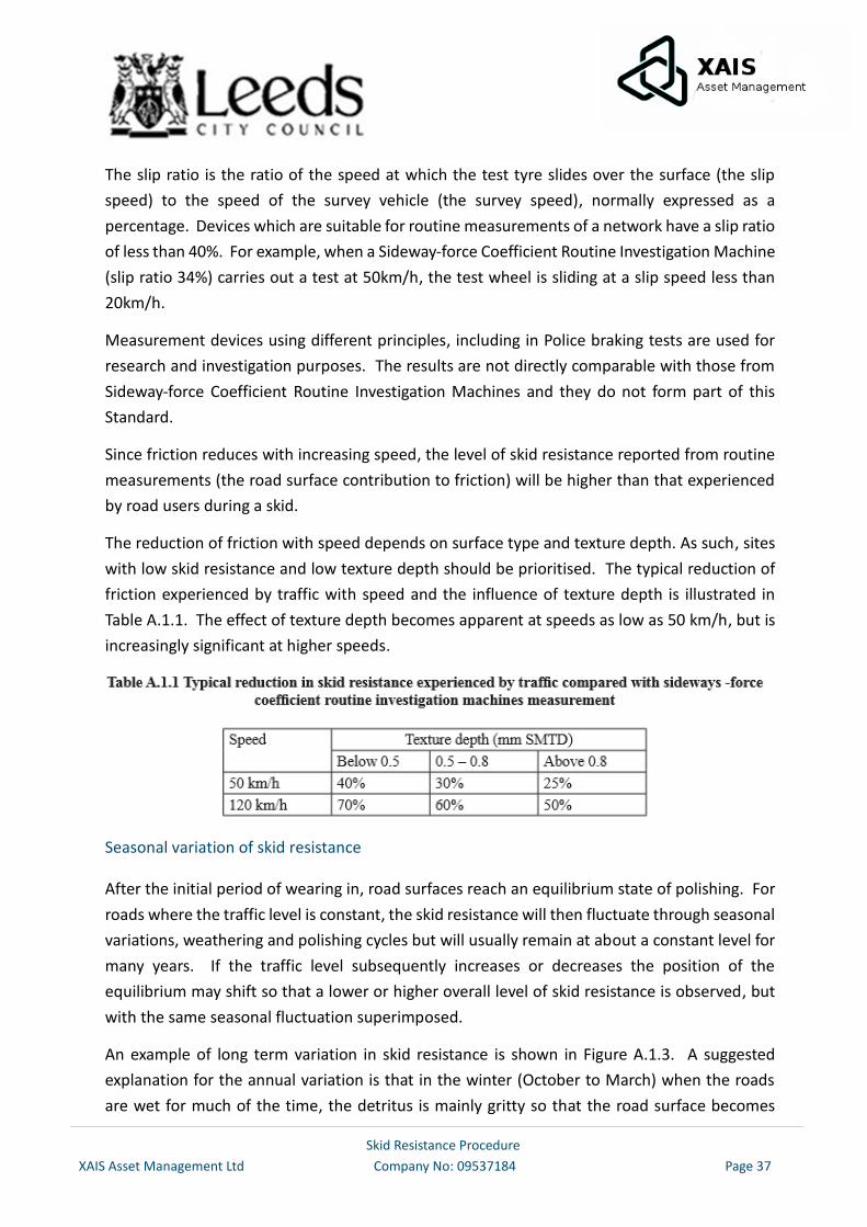
Skid Resistance Procedure
XAIS Asset Management Ltd Company No: 09537184 Page 37
The slip ratio is the ratio of the speed at which the test tyre slides over the surface (the slip
speed) to the speed of the survey vehicle (the survey speed), normally expressed as a
percentage. Devices which are suitable for routine measurements of a network have a slip ratio
of less than 40%. For example, when a Sideway-force Coefficient Routine Investigation Machine
(slip ratio 34%) carries out a test at 50km/h, the test wheel is sliding at a slip speed less than
20km/h.
Measurement devices using different principles, including in Police braking tests are used for
research and investigation purposes. The results are not directly comparable with those from
Sideway-force Coefficient Routine Investigation Machines and they do not form part of this
Standard.
Since friction reduces with increasing speed, the level of skid resistance reported from routine
measurements (the road surface contribution to friction) will be higher than that experienced
by road users during a skid.
The reduction of friction with speed depends on surface type and texture depth. As such, sites
with low skid resistance and low texture depth should be prioritised. The typical reduction of
friction experienced by traffic with speed and the influence of texture depth is illustrated in
Table A.1.1. The effect of texture depth becomes apparent at speeds as low as 50 km/h, but is
increasingly significant at higher speeds.
Seasonal variation of skid resistance
After the initial period of wearing in, road surfaces reach an equilibrium state of polishing. For
roads where the traffic level is constant, the skid resistance will then fluctuate through seasonal
variations, weathering and polishing cycles but will usually remain at about a constant level for
many years. If the traffic level subsequently increases or decreases the position of the
equilibrium may shift so that a lower or higher overall level of skid resistance is observed, but
with the same seasonal fluctuation superimposed.
An example of long term variation in skid resistance is shown in Figure A.1.3. A suggested
explanation for the annual variation is that in the winter (October to March) when the roads
are wet for much of the time, the detritus is mainly gritty so that the road surface becomes
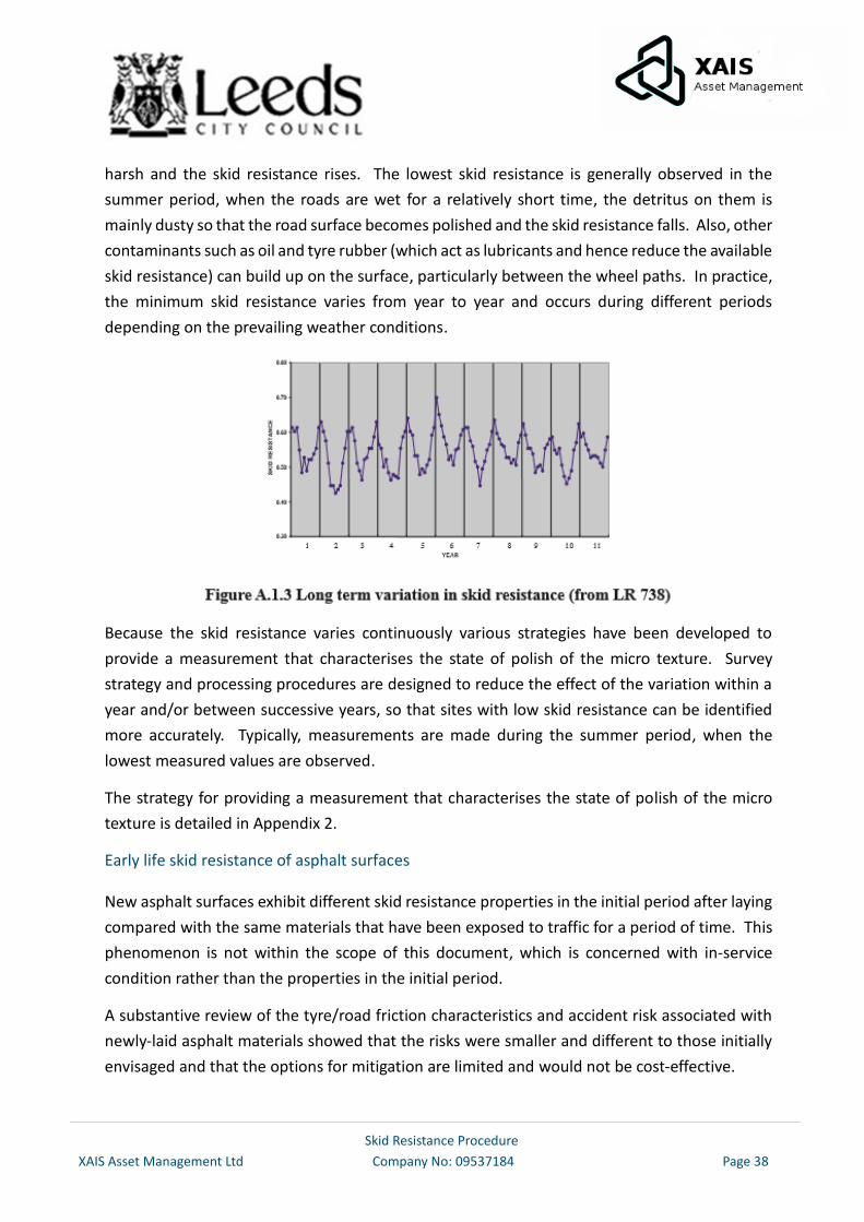
Skid Resistance Procedure
XAIS Asset Management Ltd Company No: 09537184 Page 38
harsh and the skid resistance rises. The lowest skid resistance is generally observed in the
summer period, when the roads are wet for a relatively short time, the detritus on them is
mainly dusty so that the road surface becomes polished and the skid resistance falls. Also, other
contaminants such as oil and tyre rubber (which act as lubricants and hence reduce the available
skid resistance) can build up on the surface, particularly between the wheel paths. In practice,
the minimum skid resistance varies from year to year and occurs during different periods
depending on the prevailing weather conditions.
Because the skid resistance varies continuously various strategies have been developed to
provide a measurement that characterises the state of polish of the micro texture. Survey
strategy and processing procedures are designed to reduce the effect of the variation within a
year and/or between successive years, so that sites with low skid resistance can be identified
more accurately. Typically, measurements are made during the summer period, when the
lowest measured values are observed.
The strategy for providing a measurement that characterises the state of polish of the micro
texture is detailed in Appendix 2.
Early life skid resistance of asphalt surfaces
New asphalt surfaces exhibit different skid resistance properties in the initial period after laying
compared with the same materials that have been exposed to traffic for a period of time. This
phenomenon is not within the scope of this document, which is concerned with in-service
condition rather than the properties in the initial period.
A substantive review of the tyre/road friction characteristics and accident risk associated with
newly-laid asphalt materials showed that the risks were smaller and different to those initially
envisaged and that the options for mitigation are limited and would not be cost-effective.
Skid Resistance Procedure
XAIS Asset Management Ltd Company No: 09537184 Page 39
Sections of road that exhibit these different skid resistance properties shall be identified so that
they can be excluded from certain types of analyses, as described in Chapter 5 and Appendix 2
of this Standard. The duration of this initial phase will depend on local conditions but, for the
purpose of interpreting skid resistance measurements, it is assumed that the surface has
reached an equilibrium state one year after opening to traffic on the strategic road network in
the UK.
Skid Resistance Procedure
XAIS Asset Management Ltd Company No: 09537184 Page 40
Appendix 2 – Single Annual Skid Survey (SASS) Approach to Calculation of CSC
Note: This Appendix is a copy of Annex 2 of HD28/15
Overview of SASS approach
This approach is based upon a single annual survey of the network. The method uses
measurements from the preceding 3 years to characterise the long-term skid resistance of the
network. This value is used with the mean network skid resistance in the current year to
calculate a correction factor which is applied to the current year’s data to make current values
consistent with the long-term average.
Benefits of SASS approach
The SASS approach only requires one survey for each section in each year. It is therefore
economically viable to survey the whole network each year and produce yearly CSC values.
Variation of skid resistance both within and between years can be taken into account by using
the SASS approach.
It is possible to determine the correction factors (and therefore supply CSC values) after the end
of each survey period rather than at the end of the survey season.
Shortfalls of SASS approach
The processing of the survey data in order to determine the correction factors can be labour
intensive.
The SASS approach takes account of yearly variation and therefore the calculations are affected
by maintenance carried out in the last three years. As such, sections which have had
resurfacings carried out in the last three years have to be identified and removed from the
calculation procedure for the correction factors.
If a survey is undertaken outside of the designated survey period then additional processing of
data is required to calculate a correction factor. The resulting correction factor is less suitable
resulting in less accuracy in the CSC value. Surveys undertaken outside of the target survey
period for the current year can also reduce the accuracy of correction factors calculated in the
next three years.
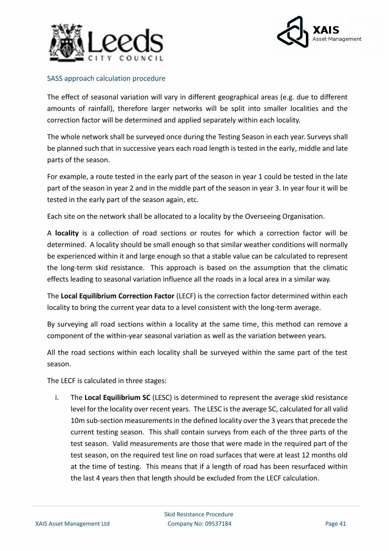
Skid Resistance Procedure
XAIS Asset Management Ltd Company No: 09537184 Page 41
SASS approach calculation procedure
The effect of seasonal variation will vary in different geographical areas (e.g. due to different
amounts of rainfall), therefore larger networks will be split into smaller localities and the
correction factor will be determined and applied separately within each locality.
The whole network shall be surveyed once during the Testing Season in each year. Surveys shall
be planned such that in successive years each road length is tested in the early, middle and late
parts of the season.
For example, a route tested in the early part of the season in year 1 could be tested in the late
part of the season in year 2 and in the middle part of the season in year 3. In year four it will be
tested in the early part of the season again, etc.
Each site on the network shall be allocated to a locality by the Overseeing Organisation.
A locality is a collection of road sections or routes for which a correction factor will be
determined. A locality should be small enough so that similar weather conditions will normally
be experienced within it and large enough so that a stable value can be calculated to represent
the long-term skid resistance. This approach is based on the assumption that the climatic
effects leading to seasonal variation influence all the roads in a local area in a similar way.
The Local Equilibrium Correction Factor (LECF) is the correction factor determined within each
locality to bring the current year data to a level consistent with the long-term average.
By surveying all road sections within a locality at the same time, this method can remove a
component of the within-year seasonal variation as well as the variation between years.
All the road sections within each locality shall be surveyed within the same part of the test
season.
The LECF is calculated in three stages:
i. The Local Equilibrium SC (LESC) is determined to represent the average skid resistance
level for the locality over recent years. The LESC is the average SC, calculated for all valid
10m sub-section measurements in the defined locality over the 3 years that precede the
current testing season. This shall contain surveys from each of the three parts of the
test season. Valid measurements are those that were made in the required part of the
test season, on the required test line on road surfaces that were at least 12 months old
at the time of testing. This means that if a length of road has been resurfaced within
the last 4 years then that length should be excluded from the LECF calculation.
Skid Resistance Procedure
XAIS Asset Management Ltd Company No: 09537184 Page 42
ii. The Local Mean SC (LMSC) is determined for the current survey. The LMSC is the average
of all valid 10m sub-sections in the locality in the current year survey.
iii. The LECF is determined by dividing the LESC by the LMSC i.e.:
LECF = LESC/LMSC
The CSC for each 10m sub-section shall be determined by multiplying the corrected SC by the LECF.
Skid Resistance Procedure
XAIS Asset Management Ltd Company No: 09537184 Page 43
Appendix 3 – The SCRIM Network - A List of sections to be surveyed annually
Sections of the following road hierarchy shall be surveyed on an annual basis and form the
SCRIM network
The SCRIM network which will be subject to skid resistance testing is subject to modification if
there are changes in crash patterns or amendments to the network.
The SCRIM network currently consists of:
The Classified Road Network
Following the release of the new Code of Practice for Well Managed Highway Infrastructure
whereby Authorities are encouraged to adopt a new ‘maintenance hierarchy’ the existing
hierarchy will be reviewed. After this review the SCRIM network is likely to change and be
updated. This will also reflect the ILs which relate to the changes.
However, inevitably there will be some sections in the above classifications where a SCRIM
survey is inappropriate and will be excluded from the annual survey. Reasons for exclusions
could include traffic calming schemes, speed humps and tables, width, height or weight
restrictions, 20mph zones or road layouts where it is not possible or safe to maintain the survey
speed.
A list of sections not surveyed is produced by the surveyor contractor on an annual basis
Certain un-classified roads are tested on an annual basis where there is a need to ascertain the
skid resistance of the existing road surface. This can be due to a number of factors including:-
• requests from other sections where work such as a new crossing/junction is planned,
• where we become aware of a unusual pattern of accidents,
• where the traffic flows are similar to that on the classified road network
This list of unclassified roads will be reviewed along with the investigatory levels at least every
3 years
Bayton Lane, Horsforth
Newhall Road, Middleton
Bullerthorpe Lane, Colton

Skidding Resistance Procedure
XAIS Asset Management Ltd Company No: 09537184 Page 44
Appendix 4 – List of ‘Other’ High Risk Situations
The following sites have been identified as ‘Other’ high risk situations and primarily include
uncontrolled crossings for vulnerable users
Note: This should be reviewed along with the Investigatory Levels at least every 3 years
<xx insert plan and/or list of sections and chainage xx>
Skidding Resistance Procedure
XAIS Asset Management Ltd Company No: 09537184 Page 45
Appendix 5 – Application of Site Categories and Investigatory Levels
Note: This Appendix is an ammended version of Annex 5 of HD28/15
Overview
This Appendix provides detailed guidance on the selection of appropriate site categories and ILs
from the range in Table 6.1. These are then followed by some examples.
The guidance given in this section is not exhaustive and therefore judgement of the risks specific
to each location shall be exercised.
Additional information such as safety reports and congestion reports may be useful when
setting site categories and the IL. They can be used to help identify higher risk situations and
where queuing is likely.
Site Category A, B & C: Non-event carriageway
Use for all non-event carriageway sections, Motorway (A), Dual Carriageway (B) and single two
way traffic (C)
For Site Category A an IL is defined as 0.35
For Site Category BR an IL is defined as 0.40 where road section signed speed >=50mph (Rural)
For Site Category BU an IL is defined as 0.35 where road section signed speed <=40mph (Urban)
For Site Category CR an IL is defined as 0.45 where road section signed speed >=50mph (Rural)
For Site Category CU an IL is defined as 0.40 where road section signed speed is <=40mph
(Urban)
BU and CU are set at the lowest ranking IL in HD28/15 as it is considered that on the more lightly
trafficked council road network there is a diminished safety risk from lower Investigatory Levels
than on the more heavily trafficked trunk roads
At junctions, use site category C for areas where traffic merges or diverges if:
The junction layout allows traffic leaving or joining the mainline to match the speed of
the mainline traffic, and/or
There is adequate taper length for merging to occur without the mainline being forced
into avoiding action.
Skidding Resistance Procedure
XAIS Asset Management Ltd Company No: 09537184 Page 46
Site Category Q: Approaches to and across minor and major junctions and approaches to
roundabouts
Use this Site Category for:
Major / minor priority junctions
o Major junctions are defined as all interconnecting classified roads
o Minor roads are defined in rural areas, those subject to 50 mph or above speed
restrictions as junctions that include all interconnecting unclassified roads
o Minor roads are defined in urban areas, those subject to 40mph or less speed
restrictions as junctions that will only include unclassified roads that are bus
routes.
Other significant accesses
These include accesses with right turning lanes, “Ghost” islands, access to supermarkets,
business parks and retail centres
Approaches to roundabouts
If the junction design and traffic volume allows the traffic to merge with/diverge from the
mainline traffic without changing speed, this Site Category is not needed (use site category B or
C instead).
For Site Category QX an IL is defined as 0.55 where road section signed speed =70mph
For Site Category QR an IL is defined as 0.50 where road section signed speed =50 or 60mph
(Rural)
For Site Category QU an IL is defined as 0.45 where road section signed speed is <=40mph
(Urban). It is set at the lowest ranking IL in HD28/15 as it is considered that on the more lightly
trafficked council road network there is a diminished safety risk from lower Investigatory Levels
than on the more heavily trafficked trunk roads
Approaches to Junctions:
For the purposes of this standard, roads involved in a junction are split into two types:
• Roads where traffic has permanent priority
• Roads where traffic is required to give way
Drivers on the road with permanent priority and are not expecting to give way, but may have to
brake sharply if a vehicle emerges unexpectedly from the intersecting road or turns right across
their path. Factors to consider are:
Skidding Resistance Procedure
XAIS Asset Management Ltd Company No: 09537184 Page 47
• Right turning vehicles from an intersecting road are at risk of a side impact with traffic
on the permanenet priority road, and the outcome of this type of crash is likely to be
severe.
• The risks increase where the speed of traffic joining or leaving the main carriageway
differs greatly from those continuing straight on. This is heavily influenced by the taper
length, provision of dedicated lanes for right-turning traffic, etc.
On the permanent priority road apply Site Category Q to the 50m approach (in the direction of
travel) to the junction and across the extent of the junction. For roads with a speed limit of
50mph or above, consider extending the approach distance, depending on the risk of traffic
having to brake unexpectedly.
For permanent priority roads with two-way traffic, consider the two directions separately to
determine the overall extent of the Site Category. The two directions should be assigned the
Site Category and IL independently so that Site Category Q is not applied on the length following
a junction.
On the road where traffic is required to give way, the risk of having to brake unexpectedly is
lower since the need to give way is indicated clearly in advance of the junction. Apply Site
Category Q to the 50m approach to the stop/give way line. Extend the distance, if necessary, to
take into account likely queues.
Where the volume of traffic using the access warrants it, treat other significant accesses (petrol
stations, superstores etc.) as for the junction, above. If the volume of traffic is low use the
appropriate non-event categories instead.
Approaches to roundabouts:
Apply Site Category Q to the 50m approach to the stop/give way line. Extend the distance, as
necessary to take into account likely regular queuing.
Do not use this Site Category for roundabouts with traffic signals or for other high risk situations
– use site category K instead.
Site Category K: Approaches to traffic signals, pedestrian crossings and other high-risk
situations
Use this category at the following locations:
Traffic Lights
Signal controlled pedestrian crossings i.e. Pelican / Toucan
Zebra pedestrian crossings
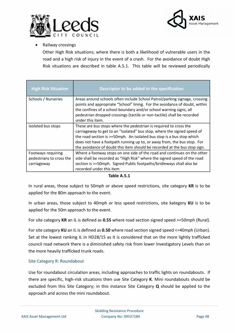
Skidding Resistance Procedure
XAIS Asset Management Ltd Company No: 09537184 Page 48
Railway crossings
Other High Risk situations; where there is both a likelihood of vulnerable users in the
road and a high risk of injury in the event of a crash. For the avoidance of doubt High
Risk situations are described in table A.5.1. This table will be reviewed periodically
taking in “lessons learnt” particularly from the initial collection.
High Risk Situation Descriptor to be added to the specification
Schools / Nurseries Areas around schools often include School Patrol/parking signage, crossing points and appropriate “School” lining. For the avoidance of doubt, within the confines of a school boundary and/or school warning signs, all pedestrian dropped crossings (tactile or non-tactile) shall be recorded under this item.
Isolated bus stops These are bus stops where the pedestrian is required to cross the carriageway to get to an “Isolated” bus stop, where the signed speed of the road section is >=50mph. An isolated bus stop is a bus stop which does not have a footpath running up to, or away from, the bus stop. For the avoidance of doubt this item should be recorded at the bus stop sign.
Footways requiring pedestrians to cross the carriageway
Where a footway stops on one side of the road and continues on the other side shall be recorded as “High Risk” where the signed speed of the road section is >=50mph. Signed Public footpaths/bridleways shall also be recorded under this item
Table A.5.1
In rural areas, those subject to 50mph or above speed restrictions, site category KR is to be
applied for the 80m approach to the event.
In urban areas, those subject to 40mph or less speed restrictions, site kategory KU is to be
applied for the 50m approach to the event.
For site category KR an IL is defined as 0.55 where road section signed speed >=50mph (Rural).
For site category KU an IL is defined as 0.50 where road section signed speed <=40mph (Urban).
Set at the lowest ranking IL in HD28/15 as it is considered that on the more lightly trafficked
council road network there is a diminished safety risk from lower Investigatory Levels than on
the more heavily trafficked trunk roads.
Site Category R: Roundabout
Use for roundabout circulation areas, including approaches to traffic lights on roundabouts. If
there are specific, high-risk situations then use Site Category K. Mini roundabouts should be
excluded from this Site Category; in this instance Site Category Q should be applied to the
approach and across the mini roundabout.
Skidding Resistance Procedure
XAIS Asset Management Ltd Company No: 09537184 Page 49
For Site Category RR an IL is defined as 0.50 where road section signed speed >=50mph (Rural)
For Site Category RU an IL is defined as 0.45 where road section signed speed <=40mph (Urban).
Set at the lowest ranking IL in HD28/15 as it is considered that on the more lightly trafficked
council road network there is a diminished safety risk from lower Investigatory Levels than on
the more heavily trafficked trunk roads
Site Category G1: Gradient 5-10% longer than 50m
On carriageways with two-way traffic, use for lengths of at least 50m with an average uphill or
downhill gradient of between 5 and 10%.
On Dual carriageways, use for lengths of at least 50m with an average downhill gradient of
between 5 and 10%.
This assessment can be based on 10m gradient data from Scanner surveys or from accurate
topographical survey data when available.
For site category G1R an IL is defined as 0.50 where road section signed speed >=50mph (Rural)
For site category G1U an IL is defined as 0.45 where road section signed speed <=40mph
(Urban). Set at the lowest ranking IL in HD28/15 as it is considered that on the more lightly
trafficked council road network there is a diminished safety risk from lower Investigatory Levels
than on the more heavily trafficked trunk roads
Site Category G2: Gradient >10% longer than 50m
On carriageways with two-way traffic, use for lengths of at least 50m with an average uphill or
downhill gradient greater than 10%.
On Dual carriageways, use for lengths of at least 50m with an average downhill gradient of 10%
of higher.
This assessment can be based on 10m gradient data from Scanner surveys or from accurate
topographical survey data when available.
For Site Category G2R an IL is defined as 0.55 where road section signed speed >=50mph (Rural)
For Site Category G2U an IL is defined as 0.50 where road section signed speed <=40mph
(Urban). Set at the lowest ranking IL in HD28/15 as it is considered that on the more lightly
trafficked council road network there is a diminished safety risk from lower Investigatory Levels
than on the more heavily trafficked trunk roads
Skidding Resistance Procedure
XAIS Asset Management Ltd Company No: 09537184 Page 50
Site Category S1: Bend radius < 500m (100m Urban)
Use for bends on carriageways with dual carriageway traffic (site category S1)
In rural areas, those subject to 50mph or above speed restrictions, the S1R site category should
only be applied for bends with radii less than 500m
In urban areas, those subject to 40mph or less speed restrictions, the S1U site category should
only be applied for bends with radii less than 100m
This site category should not generally be used for:
Short lengths, for example less than 50m, with a radius of curvature between 250m and
500m.
Roundabout exits.
The Site Category should be extended upstream and downstream to where the radius of the
road has exceeded 500m or 100m for bend radii where S1 is used at speeds lower than 50mph.
For Site Category S1R an IL is defined as 0.50 where road section signed speed >=50mph (Rural)
For Site Category S1U an IL is defined as 0.45 where road section speed <50mph (Urban). Set
as the lowest ranking Investigatory Level in HD 28/15 as it is considered that on the more lightly
trafficked council road network there is a diminished safety risk from lower Investigatory Levels
than on the more heavily trafficked trunk roads
This assessment shall be based on 10m curvature data from Scanner surveys, drawings or from
accurate topographical survey data when available.
Site Category S2: Bend radius < 500m
Use for bends on carriageways with dual carriageway traffic (category S2)
In rural areas, those subject to 50mph or above speed restrictions, the S2R site category should
only be applied for bends with radii less than 500m
In urban areas, those subject to 40mph or less speed restrictions, the S2U site category should
only be applied for bends with radii less than 100m
This category should not generally be used for:
Short lengths, for example less than 50m, with a radius of curvature between 250m and
500m.
Roundabout exits.
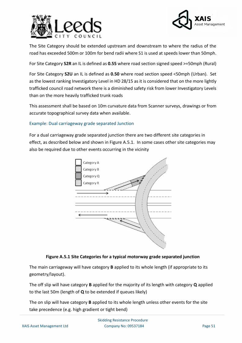
Skidding Resistance Procedure
XAIS Asset Management Ltd Company No: 09537184 Page 51
The Site Category should be extended upstream and downstream to where the radius of the
road has exceeded 500m or 100m for bend radii where S1 is used at speeds lower than 50mph.
For Site Category S2R an IL is defined as 0.55 where road section signed speed >=50mph (Rural)
For Site Category S2U an IL is defined as 0.50 where road section speed <50mph (Urban). Set
as the lowest ranking Investigatory Level in HD 28/15 as it is considered that on the more lightly
trafficked council road network there is a diminished safety risk from lower Investigatory Levels
than on the more heavily trafficked trunk roads
This assessment shall be based on 10m curvature data from Scanner surveys, drawings or from
accurate topographical survey data when available.
Example: Dual carriageway grade separated Junction
For a dual carriageway grade separated junction there are two different site categories in
effect, as described below and shown in Figure A.5.1. In some cases other site categories may
also be required due to other events occurring in the vicinity
Figure A.5.1 Site Categories for a typical motorway grade separated junction
The main carriageway will have category B applied to its whole length (if appropriate to its
geometry/layout).
The off slip will have category B applied for the majority of its length with category Q applied
to the last 50m (length of Q to be extended if queues likely)
The on slip will have category B applied to its whole length unless other events for the site
take precedence (e.g. high gradient or tight bend)
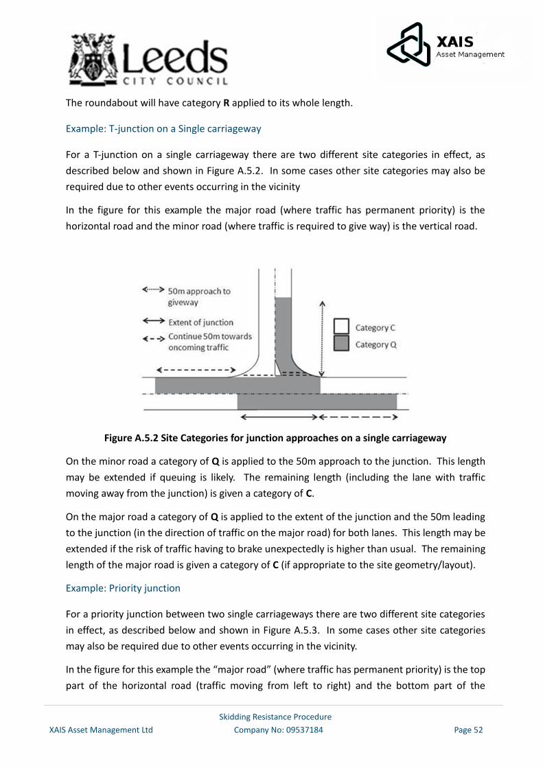
Skidding Resistance Procedure
XAIS Asset Management Ltd Company No: 09537184 Page 52
The roundabout will have category R applied to its whole length.
Example: T-junction on a Single carriageway
For a T-junction on a single carriageway there are two different site categories in effect, as
described below and shown in Figure A.5.2. In some cases other site categories may also be
required due to other events occurring in the vicinity
In the figure for this example the major road (where traffic has permanent priority) is the
horizontal road and the minor road (where traffic is required to give way) is the vertical road.
Figure A.5.2 Site Categories for junction approaches on a single carriageway
On the minor road a category of Q is applied to the 50m approach to the junction. This length
may be extended if queuing is likely. The remaining length (including the lane with traffic
moving away from the junction) is given a category of C.
On the major road a category of Q is applied to the extent of the junction and the 50m leading
to the junction (in the direction of traffic on the major road) for both lanes. This length may be
extended if the risk of traffic having to brake unexpectedly is higher than usual. The remaining
length of the major road is given a category of C (if appropriate to the site geometry/layout).
Example: Priority junction
For a priority junction between two single carriageways there are two different site categories
in effect, as described below and shown in Figure A.5.3. In some cases other site categories
may also be required due to other events occurring in the vicinity.
In the figure for this example the “major road” (where traffic has permanent priority) is the top
part of the horizontal road (traffic moving from left to right) and the bottom part of the
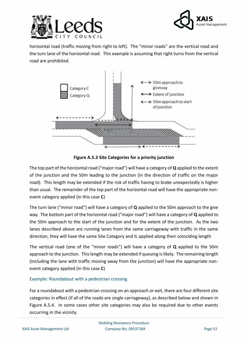
Skidding Resistance Procedure
XAIS Asset Management Ltd Company No: 09537184 Page 53
horizontal road (traffic moving from right to left). The “minor roads” are the vertical road and
the turn lane of the horizontal road. This example is assuming that right turns from the vertical
road are prohibited.
Figure A.5.3 Site Categories for a priority junction
The top part of the horizontal road (“major road”) will have a category of Q applied to the extent
of the junction and the 50m leading to the junction (in the direction of traffic on the major
road). This length may be extended if the risk of traffic having to brake unexpectedly is higher
than usual. The remainder of the top part of the horizontal road will have the appropriate non-
event category applied (in this case C)
The turn lane (“minor road”) will have a category of Q applied to the 50m approach to the give
way. The bottom part of the horizontal road (“major road”) will have a category of Q applied to
the 50m approach to the start of the junction and for the extent of the junction. As the two
lanes described above are running lanes from the same carriageway with traffic in the same
direction, they will have the same Site Category and IL applied along their coinciding length
The vertical road (one of the “minor roads”) will have a category of Q applied to the 50m
approach to the junction. This length may be extended if queuing is likely. The remaining length
(including the lane with traffic moving away from the junction) will have the appropriate non-
event category applied (in this case C)
Example: Roundabout with a pedestrian crossing
For a roundabout with a pedestrian crossing on an approach or exit, there are four different site
categories in effect (if all of the roads are single carriageway), as described below and shown in
Figure A.5.4. In some cases other site categories may also be required due to other events
occurring in the vicinity.
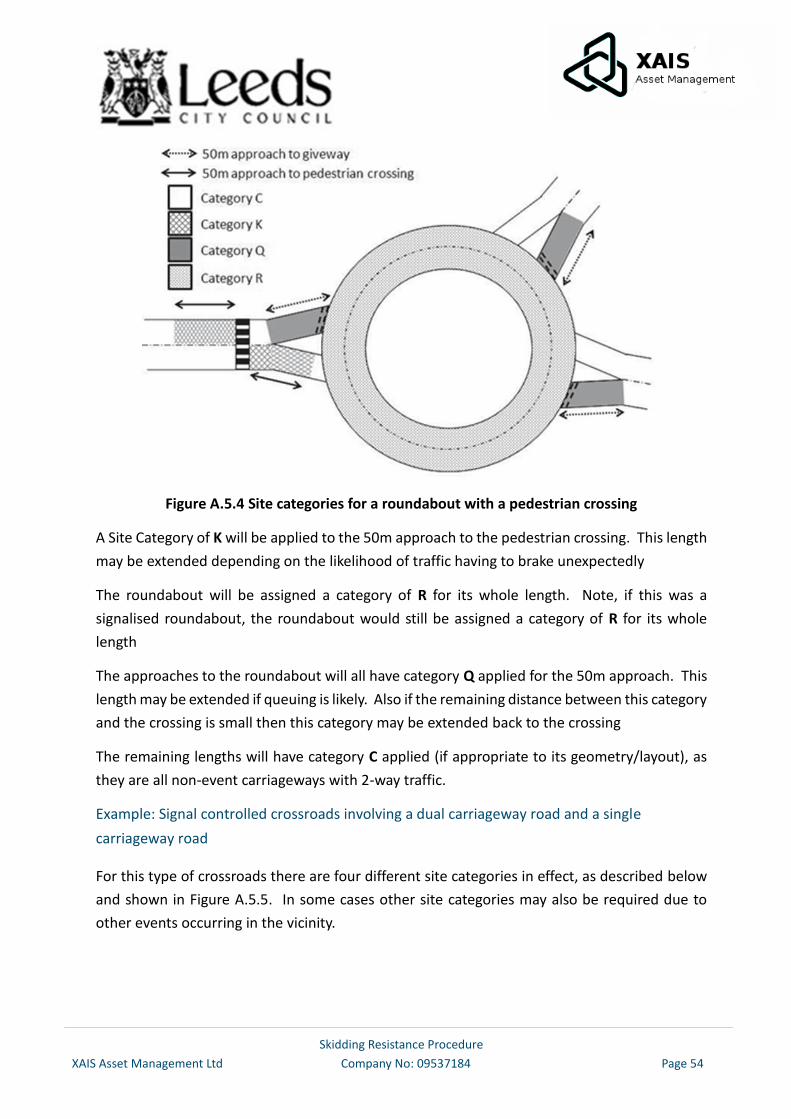
Skidding Resistance Procedure
XAIS Asset Management Ltd Company No: 09537184 Page 54
Figure A.5.4 Site categories for a roundabout with a pedestrian crossing
A Site Category of K will be applied to the 50m approach to the pedestrian crossing. This length
may be extended depending on the likelihood of traffic having to brake unexpectedly
The roundabout will be assigned a category of R for its whole length. Note, if this was a
signalised roundabout, the roundabout would still be assigned a category of R for its whole
length
The approaches to the roundabout will all have category Q applied for the 50m approach. This
length may be extended if queuing is likely. Also if the remaining distance between this category
and the crossing is small then this category may be extended back to the crossing
The remaining lengths will have category C applied (if appropriate to its geometry/layout), as
they are all non-event carriageways with 2-way traffic.
Example: Signal controlled crossroads involving a dual carriageway road and a single
carriageway road
For this type of crossroads there are four different site categories in effect, as described below
and shown in Figure A.5.5. In some cases other site categories may also be required due to
other events occurring in the vicinity.
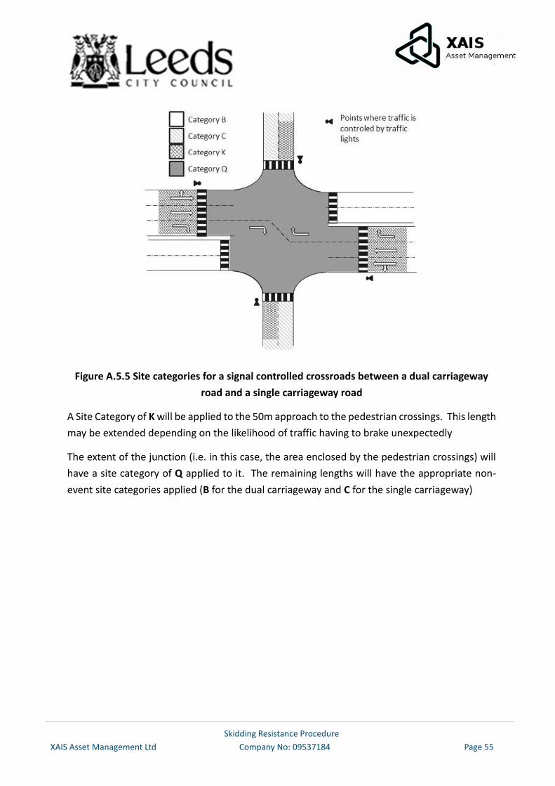
Skidding Resistance Procedure
XAIS Asset Management Ltd Company No: 09537184 Page 55
Figure A.5.5 Site categories for a signal controlled crossroads between a dual carriageway
road and a single carriageway road
A Site Category of K will be applied to the 50m approach to the pedestrian crossings. This length
may be extended depending on the likelihood of traffic having to brake unexpectedly
The extent of the junction (i.e. in this case, the area enclosed by the pedestrian crossings) will
have a site category of Q applied to it. The remaining lengths will have the appropriate non-
event site categories applied (B for the dual carriageway and C for the single carriageway)
Skidding Resistance Procedure
XAIS Asset Management Ltd Company No: 09537184 Page 56
Appendix 6 – Methodology for the Identification of Sites requiring a Detailed Investigation
The identification of sites requiring detailed investigation (the initial site score) can be carried
out as follows based on the alternative method detailed in Annex 7 of HD28/15. (The
alternative method is an alternative to the crash model, which has been developed specifically
for the Highways England road network. It is not appropriate to use this crash model on a
network outside of the Highways England’s network)
The initial site score will identify sites requiring detailed investigation and is achieved by
summing up the scores from the criteria in Table A.6.1 for each site. This method is a simplified
approximation of the Highways England’s Crash Model and refined further to include additional
points for Fatal and Wet Skid crashes.
It is nationally recognized that SCRIM is not an exact measure (it is a co-efficient) and WILL have
a seasonal variation. This seasonal variation not only varies throughout the summer months,
but can and will vary year on year. With this in mind setting a threshold has resulted in
significant fluctuations in the number of sites identified. Therefore, the council use the
following methodology to identify a minimum number of 200 sites.
Note: The score for the 200th site is taken as the minimum value to identify sites requiring
detailed investigation. This is subject to change to ensure a minimum 200 sites have a detailed
inspection. For example, in 2017 the 200th site had a value of 22 which produced 233 sites for
detailed investigation.
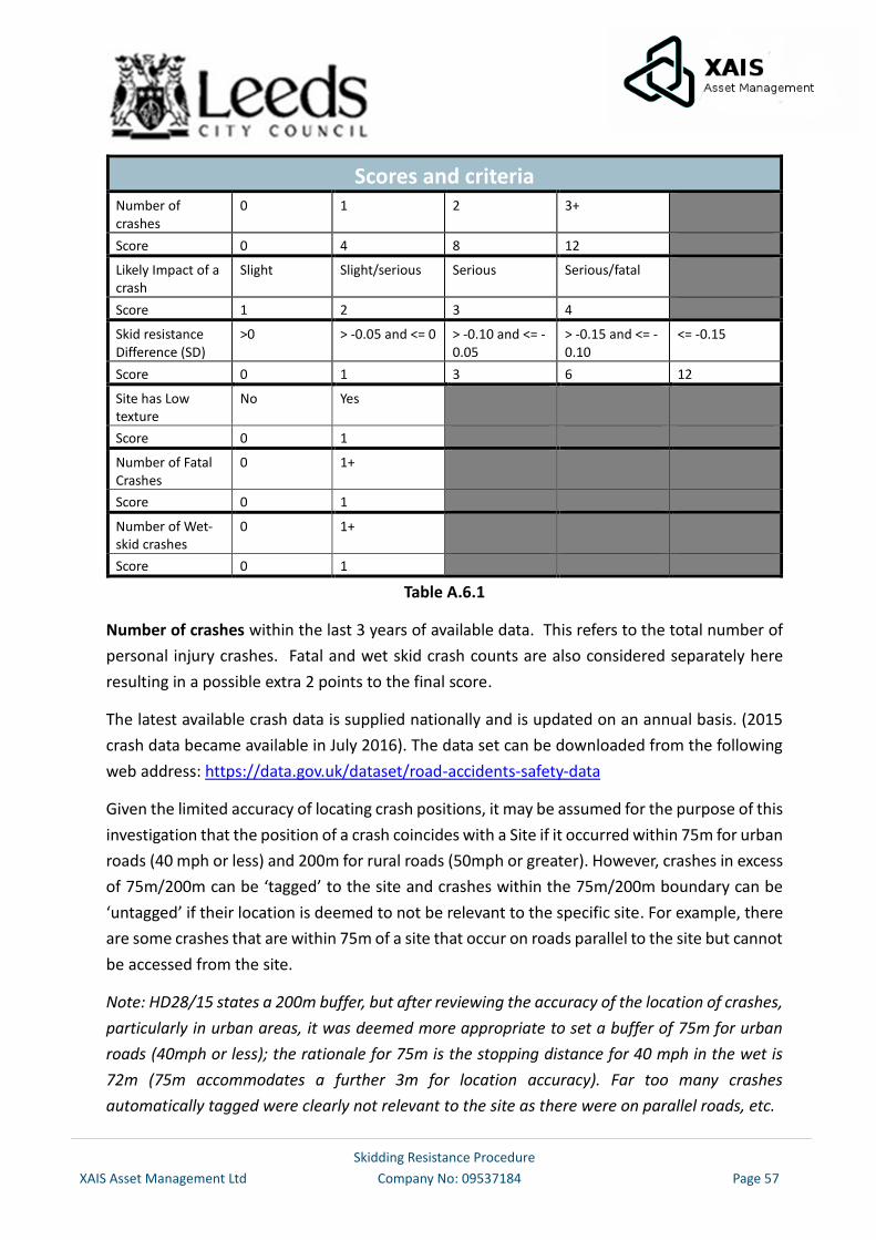
Skidding Resistance Procedure
XAIS Asset Management Ltd Company No: 09537184 Page 57
Scores and criteria Number of crashes
0 1 2 3+
Score 0 4 8 12
Likely Impact of a crash
Slight Slight/serious Serious Serious/fatal
Score 1 2 3 4
Skid resistance Difference (SD)
>0 > -0.05 and <= 0 > -0.10 and <= -0.05
> -0.15 and <= -0.10
<= -0.15
Score 0 1 3 6 12
Site has Low texture
No Yes
Score 0 1
Number of Fatal Crashes
0 1+
Score 0 1
Number of Wet-skid crashes
0 1+
Score 0 1
Table A.6.1
Number of crashes within the last 3 years of available data. This refers to the total number of
personal injury crashes. Fatal and wet skid crash counts are also considered separately here
resulting in a possible extra 2 points to the final score.
The latest available crash data is supplied nationally and is updated on an annual basis. (2015
crash data became available in July 2016). The data set can be downloaded from the following
web address: https://data.gov.uk/dataset/road-accidents-safety-data
Given the limited accuracy of locating crash positions, it may be assumed for the purpose of this
investigation that the position of a crash coincides with a Site if it occurred within 75m for urban
roads (40 mph or less) and 200m for rural roads (50mph or greater). However, crashes in excess
of 75m/200m can be ‘tagged’ to the site and crashes within the 75m/200m boundary can be
‘untagged’ if their location is deemed to not be relevant to the specific site. For example, there
are some crashes that are within 75m of a site that occur on roads parallel to the site but cannot
be accessed from the site.
Note: HD28/15 states a 200m buffer, but after reviewing the accuracy of the location of crashes,
particularly in urban areas, it was deemed more appropriate to set a buffer of 75m for urban
roads (40mph or less); the rationale for 75m is the stopping distance for 40 mph in the wet is
72m (75m accommodates a further 3m for location accuracy). Far too many crashes
automatically tagged were clearly not relevant to the site as there were on parallel roads, etc.
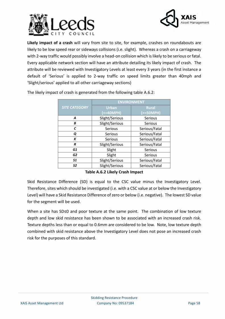
Skidding Resistance Procedure
XAIS Asset Management Ltd Company No: 09537184 Page 58
Likely impact of a crash will vary from site to site, for example, crashes on roundabouts are
likely to be low speed rear or sideways collisions (i.e. slight). Whereas a crash on a carriageway
with 2-way traffic would possibly involve a head-on collision which is likely to be serious or fatal.
Every applicable network section will have an attribute detailing its likely impact of crash. The
attribute will be reviewed with Investigatory Levels at least every 3 years (in the first instance a
default of ‘Serious’ is applied to 2-way traffic on speed limits greater than 40mph and
‘Slight/serious’ applied to all other carriageway sections)
The likely impact of crash is generated from the following table A.6.2:
SITE CATEGORY
ENVIRONMENT
Urban (<=40MPH)
Rural (>=50MPH)
A Slight/Serious Serious B Slight/Serious Serious
C Serious Serious/Fatal Q Serious Serious/Fatal K Serious Serious/Fatal R Slight/Serious Serious/Fatal
G1 Slight Serious
G2 Slight Serious S1 Slight/Serious Serious/Fatal S2 Slight/Serious Serious/Fatal
Table A.6.2 Likely Crash Impact
Skid Resistance Difference (SD) is equal to the CSC value minus the Investigatory Level.
Therefore, sites which should be investigated (i.e. with a CSC value at or below the Investigatory
Level) will have a Skid Resistance Difference of zero or below (i.e. negative). The lowest SD value
for the segment will be used.
When a site has SD≤0 and poor texture at the same point. The combination of low texture
depth and low skid resistance has been shown to be associated with an increased crash risk.
Texture depths less than or equal to 0.6mm are considered to be low. Note, low texture depth
combined with skid resistance above the Investigatory Level does not pose an increased crash
risk for the purposes of this standard.
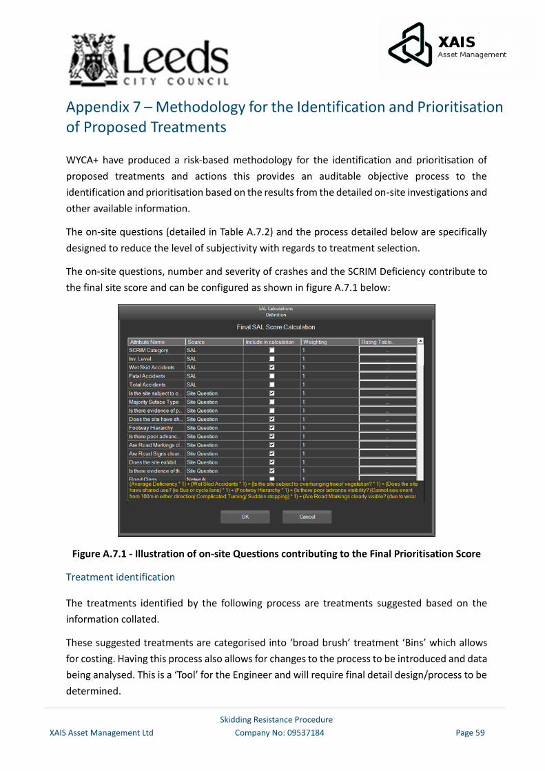
Skidding Resistance Procedure
XAIS Asset Management Ltd Company No: 09537184 Page 59
Appendix 7 – Methodology for the Identification and Prioritisation of Proposed Treatments
WYCA+ have produced a risk-based methodology for the identification and prioritisation of
proposed treatments and actions this provides an auditable objective process to the
identification and prioritisation based on the results from the detailed on-site investigations and
other available information.
The on-site questions (detailed in Table A.7.2) and the process detailed below are specifically
designed to reduce the level of subjectivity with regards to treatment selection.
The on-site questions, number and severity of crashes and the SCRIM Deficiency contribute to
the final site score and can be configured as shown in figure A.7.1 below:
Figure A.7.1 - Illustration of on-site Questions contributing to the Final Prioritisation Score
Treatment identification
The treatments identified by the following process are treatments suggested based on the
information collated.
These suggested treatments are categorised into ‘broad brush’ treatment ‘Bins’ which allows
for costing. Having this process also allows for changes to the process to be introduced and data
being analysed. This is a ‘Tool’ for the Engineer and will require final detail design/process to be
determined.
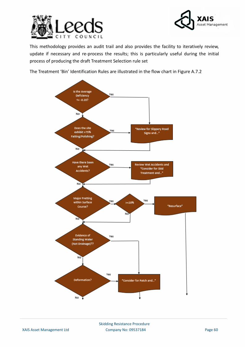
Skidding Resistance Procedure
XAIS Asset Management Ltd Company No: 09537184 Page 60
This methodology provides an audit trail and also provides the facility to iteratively review,
update if necessary and re-process the results; this is particularly useful during the initial
process of producing the draft Treatment Selection rule set
The Treatment ‘Bin’ Identification Rules are illustrated in the flow chart in Figure A.7.2
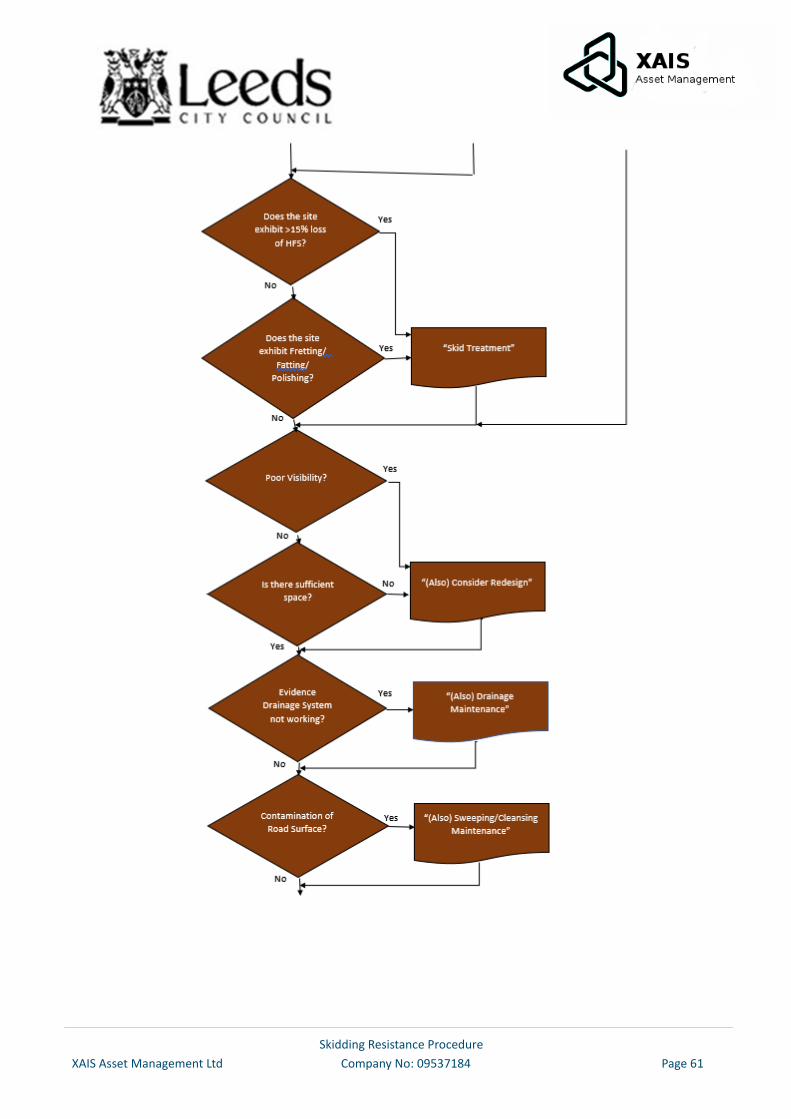
Skidding Resistance Procedure
XAIS Asset Management Ltd Company No: 09537184 Page 61
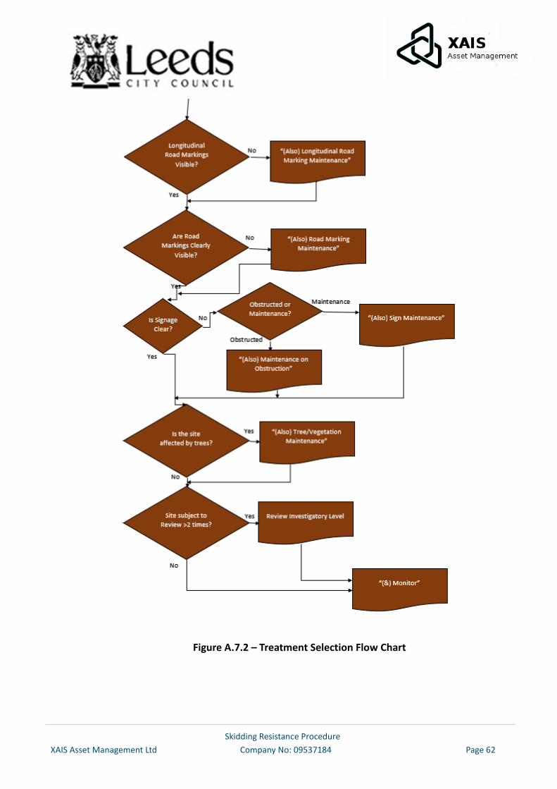
Skidding Resistance Procedure
XAIS Asset Management Ltd Company No: 09537184 Page 62
Figure A.7.2 – Treatment Selection Flow Chart
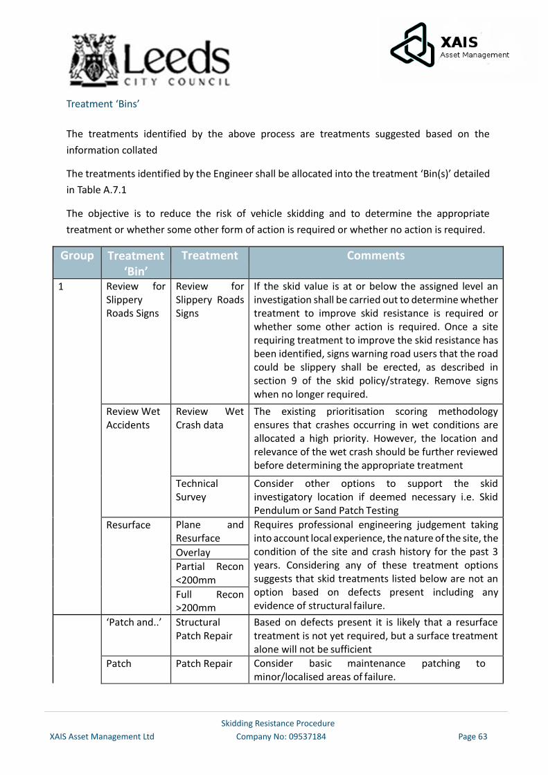
Skidding Resistance Procedure
XAIS Asset Management Ltd Company No: 09537184 Page 63
Treatment ‘Bins’
The treatments identified by the above process are treatments suggested based on the
information collated
The treatments identified by the Engineer shall be allocated into the treatment ‘Bin(s)’ detailed
in Table A.7.1
The objective is to reduce the risk of vehicle skidding and to determine the appropriate
treatment or whether some other form of action is required or whether no action is required.
Group Treatment ‘Bin’
Treatment Comments
1 Review for Slippery Roads Signs
Review for Slippery Roads Signs
If the skid value is at or below the assigned level an investigation shall be carried out to determine whether treatment to improve skid resistance is required or whether some other action is required. Once a site requiring treatment to improve the skid resistance has been identified, signs warning road users that the road could be slippery shall be erected, as described in section 9 of the skid policy/strategy. Remove signs when no longer required.
Review Wet Accidents
Review Wet Crash data
The existing prioritisation scoring methodology ensures that crashes occurring in wet conditions are allocated a high priority. However, the location and relevance of the wet crash should be further reviewed before determining the appropriate treatment
Technical Survey
Consider other options to support the skid investigatory location if deemed necessary i.e. Skid Pendulum or Sand Patch Testing
Resurface Plane and Resurface
Requires professional engineering judgement taking into account local experience, the nature of the site, the condition of the site and crash history for the past 3 years. Considering any of these treatment options suggests that skid treatments listed below are not an option based on defects present including any evidence of structural failure.
Overlay
Partial Recon <200mm
Full Recon >200mm
‘Patch and..’ Structural Patch Repair
Based on defects present it is likely that a resurface treatment is not yet required, but a surface treatment alone will not be sufficient
Patch Patch Repair Consider basic maintenance patching to minor/localised areas of failure.
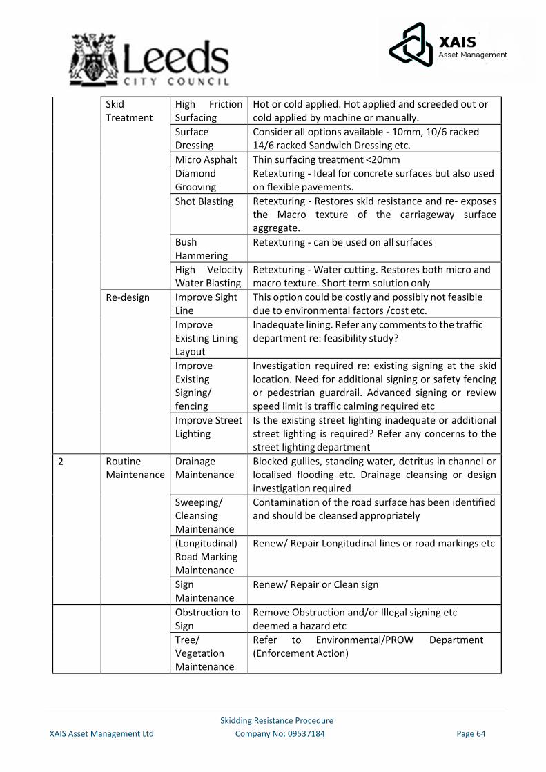
Skidding Resistance Procedure
XAIS Asset Management Ltd Company No: 09537184 Page 64
Skid Treatment
High Friction Surfacing
Hot or cold applied. Hot applied and screeded out or cold applied by machine or manually.
Surface Dressing
Consider all options available - 10mm, 10/6 racked 14/6 racked Sandwich Dressing etc.
Micro Asphalt Thin surfacing treatment <20mm
Diamond Grooving
Retexturing - Ideal for concrete surfaces but also used on flexible pavements.
Shot Blasting Retexturing - Restores skid resistance and re- exposes the Macro texture of the carriageway surface aggregate.
Bush Hammering
Retexturing - can be used on all surfaces
High Velocity Water Blasting
Retexturing - Water cutting. Restores both micro and macro texture. Short term solution only
Re-design Improve Sight Line
This option could be costly and possibly not feasible due to environmental factors /cost etc.
Improve Existing Lining Layout
Inadequate lining. Refer any comments to the traffic department re: feasibility study?
Improve Existing Signing/ fencing
Investigation required re: existing signing at the skid location. Need for additional signing or safety fencing or pedestrian guardrail. Advanced signing or review speed limit is traffic calming required etc
Improve Street Lighting
Is the existing street lighting inadequate or additional street lighting is required? Refer any concerns to the street lighting department
2 Routine Maintenance
Drainage Maintenance
Blocked gullies, standing water, detritus in channel or localised flooding etc. Drainage cleansing or design investigation required
Sweeping/ Cleansing Maintenance
Contamination of the road surface has been identified and should be cleansed appropriately
(Longitudinal) Road Marking Maintenance
Renew/ Repair Longitudinal lines or road markings etc
Sign Maintenance
Renew/ Repair or Clean sign
Obstruction to Sign
Remove Obstruction and/or Illegal signing etc deemed a hazard etc
Tree/ Vegetation Maintenance
Refer to Environmental/PROW Department (Enforcement Action)
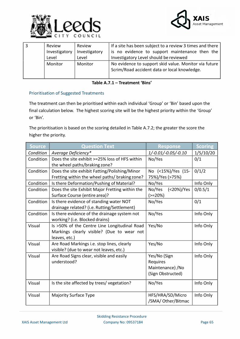
Skidding Resistance Procedure
XAIS Asset Management Ltd Company No: 09537184 Page 65
3 Review Investigatory Level
Review Investigatory Level
If a site has been subject to a review 3 times and there is no evidence to support maintenance then the Investigatory Level should be reviewed
Monitor Monitor No evidence to support skid value. Monitor via future Scrim/Road accident data or local knowledge.
Table A.7.1 – Treatment ‘Bins’
Prioritisation of Suggested Treatments
The treatment can then be prioritised within each individual ‘Group’ or ‘Bin’ based upon the
final calculation below. The highest scoring site will be the highest priority within the ‘Group’
or ‘Bin’.
The prioritisation is based on the scoring detailed in Table A.7.2; the greater the score the
higher the priority.
Source Question Text Response Scoring Condition Average Deficiency* 1/-0.01/-0.05/-0.10 1/5/10/20
Condition Does the site exhibit >=25% loss of HFS within the wheel paths/braking zone?
No/Yes 0/1
Condition Does the site exhibit Fatting/Polishing/Minor Fretting within the wheel paths/ braking zone?
No (<15%)/Yes (15- 75%)/Yes (>75%)
0/1/2
Condition Is there Deformation/Pushing of Material? No/Yes Info Only
Condition Does the site Exhibit Major Fretting within the Surface Course (entire area)?
No/Yes (<20%)/Yes (>=20%)
0/0.5/1
Condition Is there evidence of standing water NOT drainage related? (i.e. Rutting/Settlement)
No/Yes 0/1
Condition Is there evidence of the drainage system not working? (i.e. Blocked drains)
No/Yes Info Only
Visual Is >50% of the Centre Line Longitudinal Road Markings clearly visible? (Due to wear not leaves, etc.)
Yes/No Info Only
Visual Are Road Markings i.e. stop lines, clearly visible? (due to wear not leaves, etc.)
Yes/No Info Only
Visual Are Road Signs clear, visible and easily understood?
Yes/No (Sign Requires Maintenance) /No (Sign Obstructed)
Info Only
Visual Is the site affected by trees/ vegetation? No/Yes Info Only
Visual Majority Surface Type HFS/HRA/SD/Micro /SMA/ Other/Bitmac
Info Only
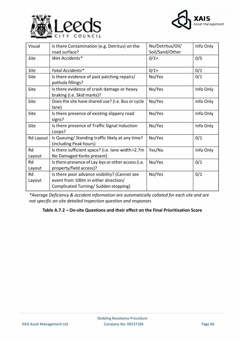
Skidding Resistance Procedure
XAIS Asset Management Ltd Company No: 09537184 Page 66
Visual Is there Contamination (e.g. Detritus) on the road surface?
No/Detritus/Oil/ Soil/Sand/Other
Info Only
Site Wet Accidents* 0/1+ 0/5
Site Fatal Accidents* 0/1+ 0/1
Site Is there evidence of past patching repairs/ pothole fillings?
No/Yes 0/1
Site Is there evidence of crash damage or heavy braking (i.e. Skid marks)?
No/Yes Info Only
Site Does the site have shared use? (i.e. Bus or cycle lane)
No/Yes Info Only
Site Is there presence of existing slippery road signs?
No/Yes Info Only
Site Is there presence of Traffic Signal Induction Loops?
No/Yes Info Only
Rd Layout Is Queuing/ Standing traffic likely at any time? (including Peak hours)
No/Yes 0/1
Rd Layout
Is there sufficient space? (i.e. lane width >2.7m No Damaged Kerbs present)
Yes/No Info Only
Rd Layout
Is there presence of Lay-bys or other access (i.e. property/field access)?
No/Yes 0/1
Rd Layout
Is there poor advance visibility? (Cannot see event from 100m in either direction/ Complicated Turning/ Sudden stopping)
No/Yes 0/1
*Average Deficiency & accident information are automatically collated for each site and are not specific on-site detailed Inspection question and responses
Table A.7.2 – On-site Questions and their effect on the Final Prioritisation Score
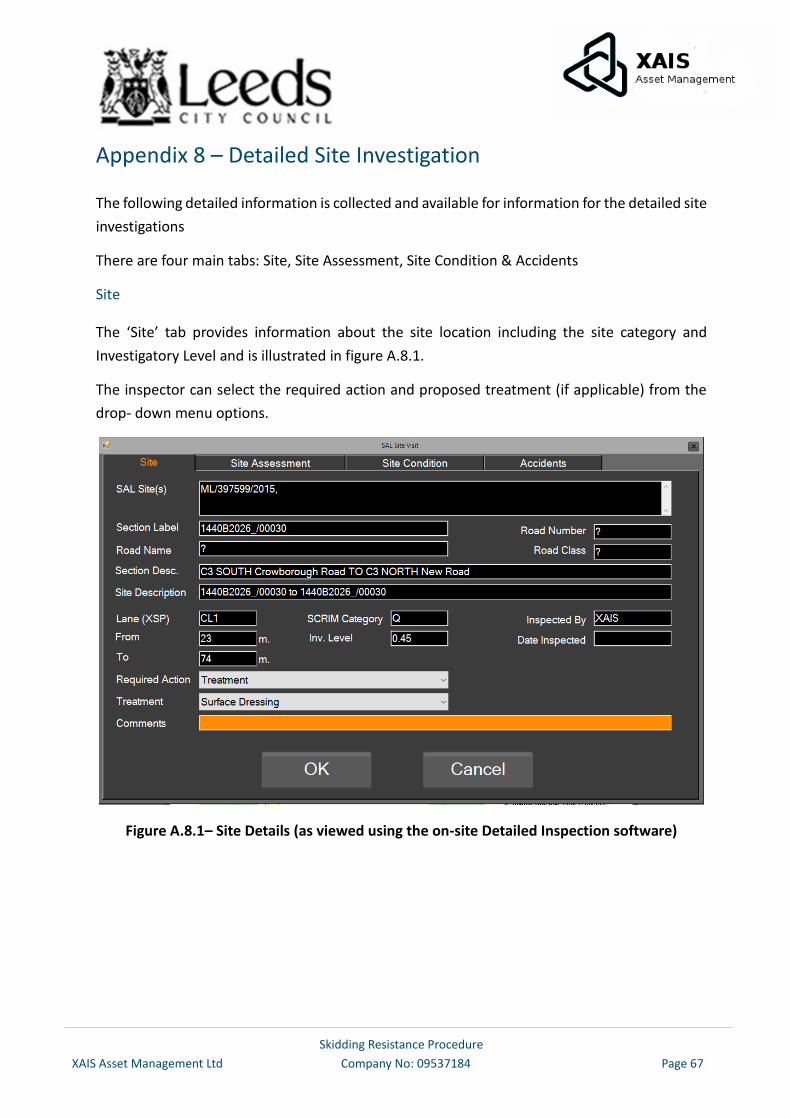
Skidding Resistance Procedure
XAIS Asset Management Ltd Company No: 09537184 Page 67
Appendix 8 – Detailed Site Investigation
The following detailed information is collected and available for information for the detailed site
investigations
There are four main tabs: Site, Site Assessment, Site Condition & Accidents
Site
The ‘Site’ tab provides information about the site location including the site category and
Investigatory Level and is illustrated in figure A.8.1.
The inspector can select the required action and proposed treatment (if applicable) from the
drop- down menu options.
Figure A.8.1– Site Details (as viewed using the on-site Detailed Inspection software)
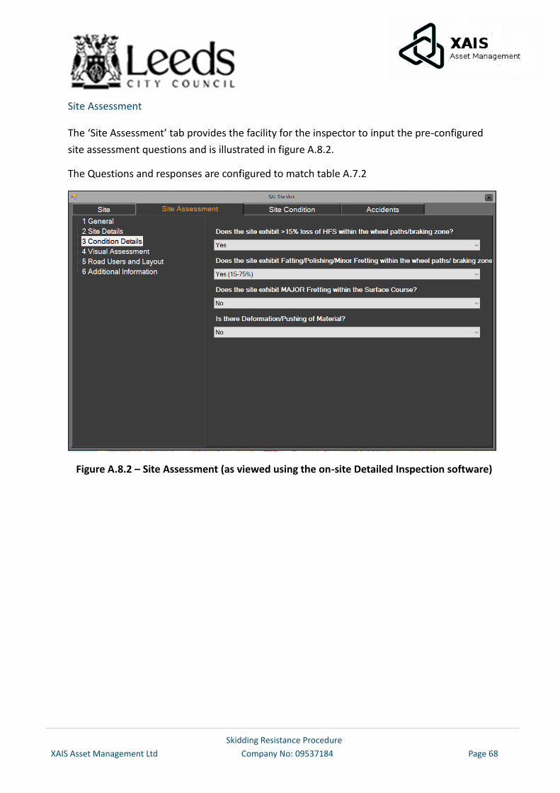
Skidding Resistance Procedure
XAIS Asset Management Ltd Company No: 09537184 Page 68
Site Assessment
The ‘Site Assessment’ tab provides the facility for the inspector to input the pre-configured
site assessment questions and is illustrated in figure A.8.2.
The Questions and responses are configured to match table A.7.2
Figure A.8.2 – Site Assessment (as viewed using the on-site Detailed Inspection software)
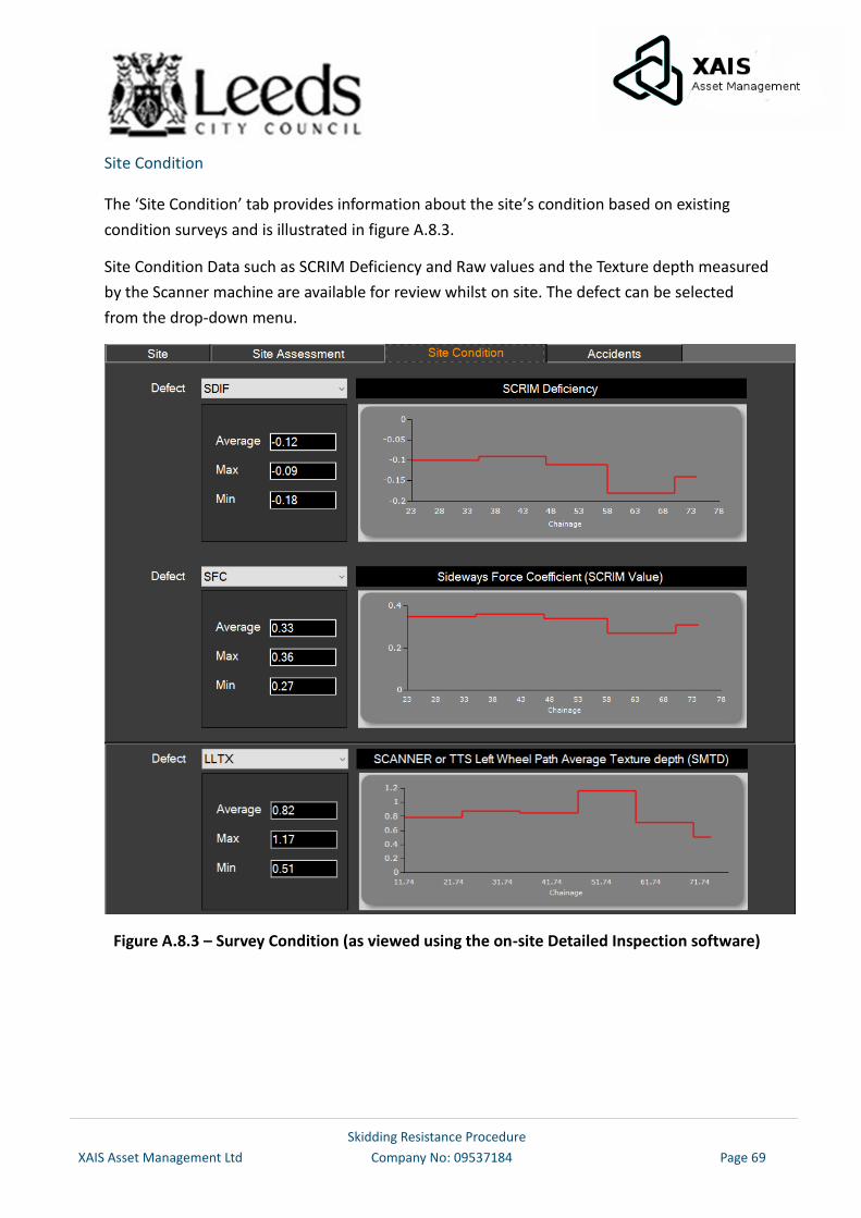
Skidding Resistance Procedure
XAIS Asset Management Ltd Company No: 09537184 Page 69
Site Condition
The ‘Site Condition’ tab provides information about the site’s condition based on existing
condition surveys and is illustrated in figure A.8.3.
Site Condition Data such as SCRIM Deficiency and Raw values and the Texture depth measured
by the Scanner machine are available for review whilst on site. The defect can be selected
from the drop-down menu.
Figure A.8.3 – Survey Condition (as viewed using the on-site Detailed Inspection software)
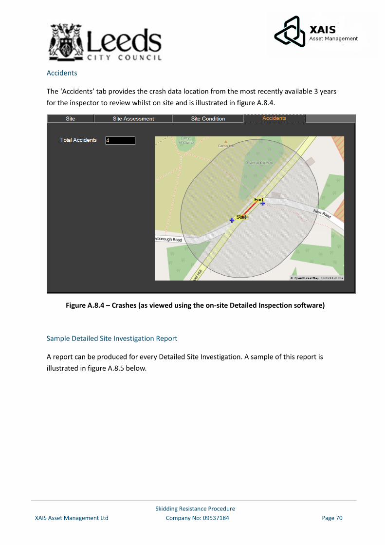
Skidding Resistance Procedure
XAIS Asset Management Ltd Company No: 09537184 Page 70
Accidents
The ‘Accidents’ tab provides the crash data location from the most recently available 3 years
for the inspector to review whilst on site and is illustrated in figure A.8.4.
Figure A.8.4 – Crashes (as viewed using the on-site Detailed Inspection software)
Sample Detailed Site Investigation Report
A report can be produced for every Detailed Site Investigation. A sample of this report is
illustrated in figure A.8.5 below.
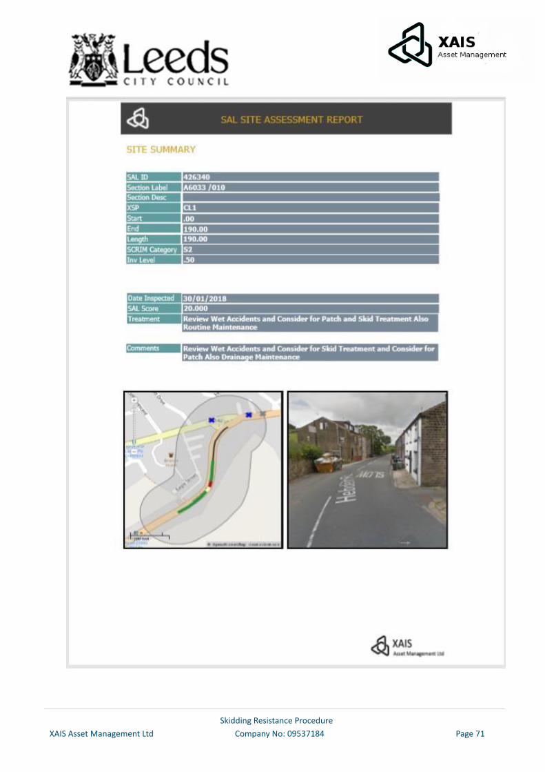
Skidding Resistance Procedure
XAIS Asset Management Ltd Company No: 09537184 Page 71
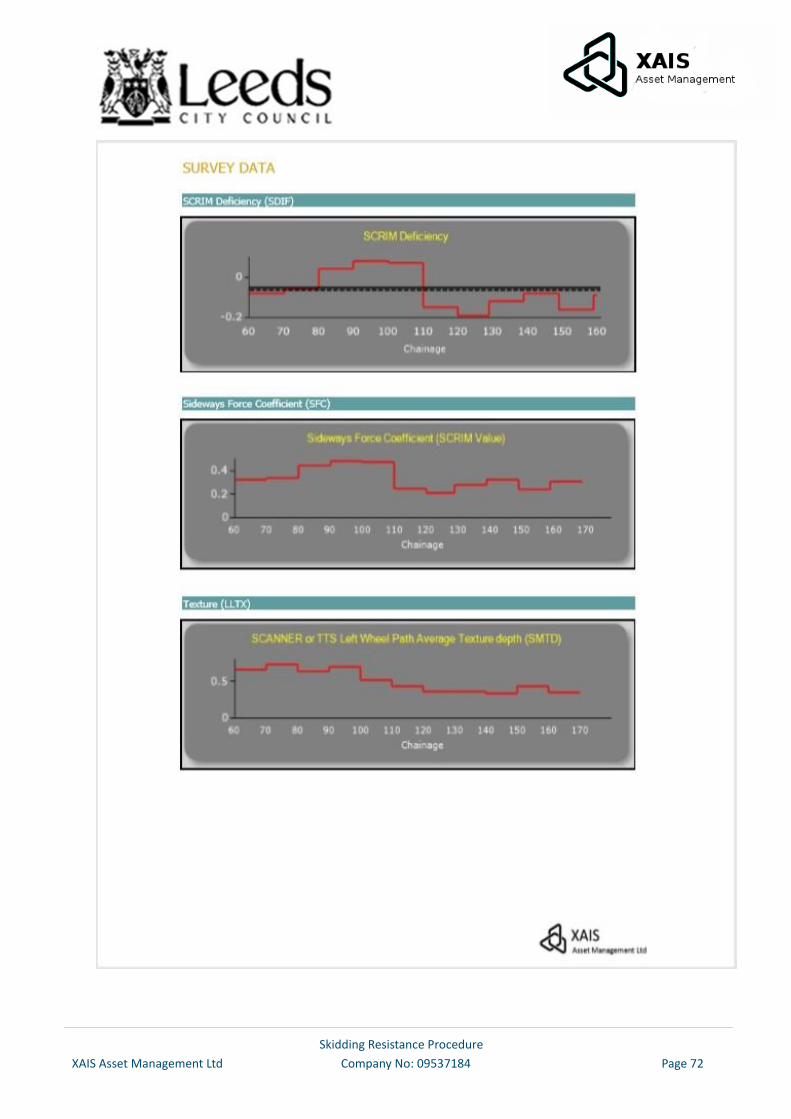
Skidding Resistance Procedure
XAIS Asset Management Ltd Company No: 09537184 Page 72
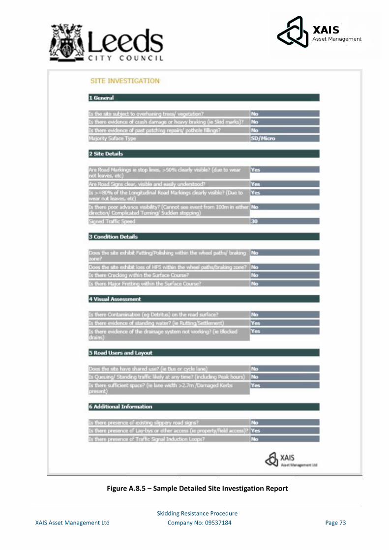
Skidding Resistance Procedure
XAIS Asset Management Ltd Company No: 09537184 Page 73
Figure A.8.5 – Sample Detailed Site Investigation Report