Embed Size (px)
Citation preview
Inst
alla
tion
& O
pera
tion
Gui
de
P/N 05-3627A01, Rev. D.1JANUARY 2003
Covering LEDR 400S/F, 700S, 900S/F, 1400S/F Models
Including Protected (1+1) and Space Diversity Versions
LEDR SeriesDigital Microwave Radios
Microwave Data Systems Inc.
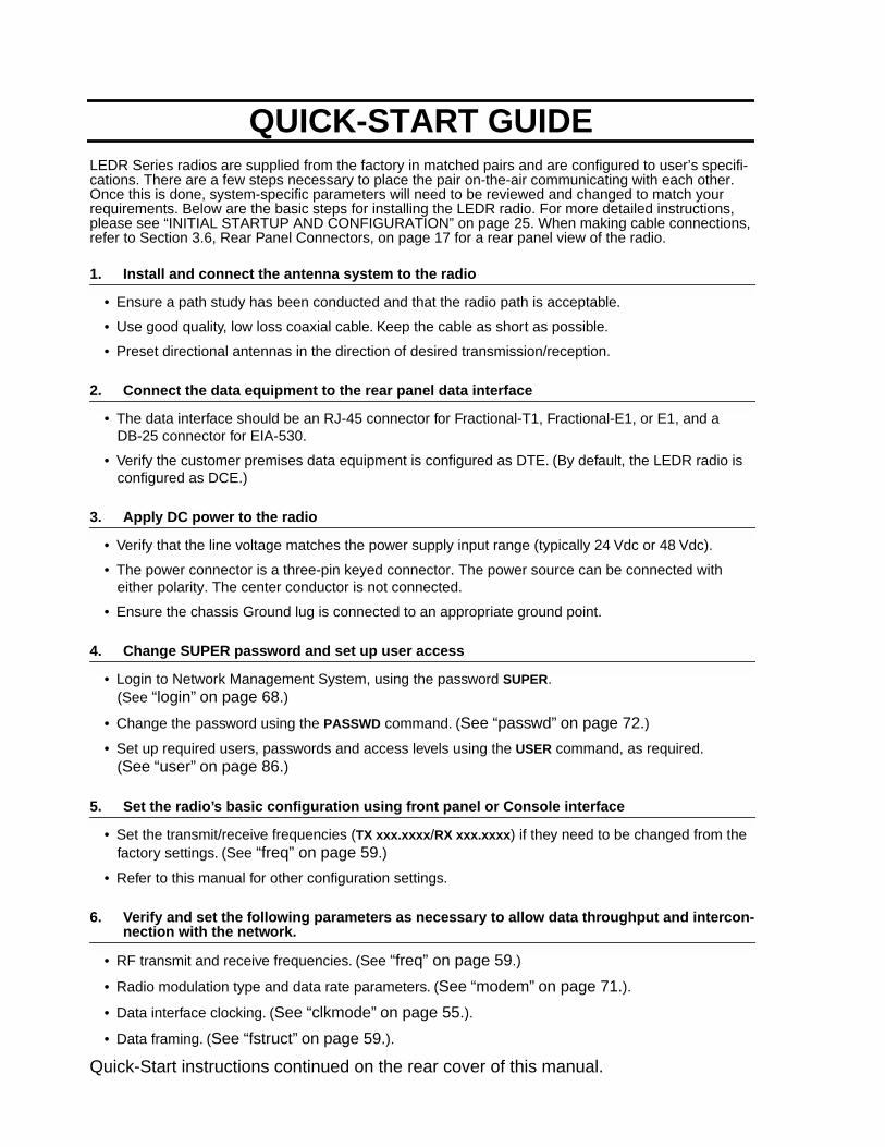
LEDR Series radios are supplied from the factory in matched pairs and are configured to user’s specifi-cations. There are a few steps necessary to place the pair on-the-air communicating with each other. Once this is done, system-specific parameters will need to be reviewed and changed to match your requirements. Below are the basic steps for installing the LEDR radio. For more detailed instructions, please see “INITIAL STARTUP AND CONFIGURATION” on page 25. When making cable connections, refer to Section 3.6,
Rear Panel Connectors
, on page 17 for a rear panel view of the radio.
1. Install and connect the antenna system to the radio
• Ensure a path study has been conducted and that the radio path is acceptable.
• Use good quality, low loss coaxial cable. Keep the cable as short as possible.
• Preset directional antennas in the direction of desired transmission/reception.
2. Connect the data equipment to the rear panel data interface
• The data interface should be an RJ-45 connector for Fractional-T1, Fractional-E1, or E1, and a DB-25 connector for EIA-530.
• Verify the customer premises data equipment is configured as DTE. (By default, the LEDR radio is configured as DCE.)
3. Apply DC power to the radio
• Verify that the line voltage matches the power supply input range (typically 24 Vdc or 48 Vdc).
• The power connector is a three-pin keyed connector. The power source can be connected with either polarity. The center conductor is
not
connected.
• Ensure the chassis Ground lug is connected to an appropriate ground point.
4. Change SUPER password and set up user access
• Login to Network Management System, using the password
SUPER
. (See
“login” on page 68
.)
• Change the password using the
PASSWD
command. (
See “passwd” on page 72.
)
• Set up required users, passwords and access levels using the
USER
command, as required.(
See “user” on page 86.
)
5. Set the radio’s basic configuration using front panel or Console interface
• Set the transmit/receive frequencies (
TX xxx.xxxx
/
RX xxx.xxxx
) if they need to be changed from the factory settings. (See
“freq” on page 59
.)
• Refer to this manual for other configuration settings.
6. Verify and set the following parameters as necessary to allow data throughput and intercon-
nection with the network.
• RF transmit and receive frequencies. (See
“freq” on page 59
.)
• Radio modulation type and data rate parameters. (
See “modem” on page 71.
).
• Data interface clocking. (
See “clkmode” on page 55.
).
• Data framing. (
See “fstruct” on page 59.
).
Quick-Start instructions continued on the rear cover of this manual.
QUICK-START GUIDE
MDS 05-3627A01, Rev. D LEDR Series I/O Guide i
TABLE OF CONTENTS
1.0 INTRODUCTION .................................................................................................................. 1
1.1 Product Description .......................................................................................................................11.2 LEDR Features ..............................................................................................................................21.3 Typical Applications .......................................................................................................................31.4 Protected Configuration .................................................................................................................3
2.0 MODEL NUMBER CODES................................................................................................... 4
3.0 HARDWARE INSTALLATION AND BASIC INTERFACE REQUIREMENTS ........................ 7
3.1 Introduction ....................................................................................................................................73.2 General Requirements ..................................................................................................................7
Site Selection ...................................................................................................................................8Terrain and Signal Strength .............................................................................................................8On-the-Air Test .................................................................................................................................9A Word About Interference...............................................................................................................9
3.3 Antenna and Feedline Selection ..................................................................................................10Antennas........................................................................................................................................10Feedlines .......................................................................................................................................11
3.4 Radio Mounting ...........................................................................................................................13Maximizing RSSI............................................................................................................................13Attaching the Rack Mounting Brackets ..........................................................................................13
3.5 Front Panel ..................................................................................................................................14Indicators, Text Display and Navigation Keys.................................................................................14Connectors.....................................................................................................................................16
3.6 Rear Panel Connectors ...............................................................................................................17Connector Locations ......................................................................................................................17Ground Stud...................................................................................................................................18Antenna/TX—RF Connector ..........................................................................................................18RX—RF Connector ........................................................................................................................18G.703/Expansion Data...................................................................................................................19Ethernet .........................................................................................................................................19EIA-530-A ......................................................................................................................................20Service Channel ............................................................................................................................20Alarm I/O........................................................................................................................................21DC Power Input (Primary Power) ...................................................................................................22Protected Configuration Connections ............................................................................................23
3.7 Bandwidths, Data Rates and Modulation Types ..........................................................................233.8 Transmit Clock Selection (Subrate Radios Only) .........................................................................24
4.0 INITIAL STARTUP AND CONFIGURATION ....................................................................... 25
4.1 Introduction ..................................................................................................................................25
ii LEDR Series I/O Guide MDS 05-3627A01, Rev. D
4.2 STEP 1—Power up the LEDR Radios .........................................................................................254.3 STEP 2—Establish Communications with the Radio ..................................................................264.4 STEP 3—Make Initial Login to Radio ..........................................................................................264.5 STEP 4—Change the SUPER Password ....................................................................................274.6 STEP 5—Review Essential Operating Parameters .....................................................................284.7 STEP 6—Set TCP/IP Settings to Enable SNMP and/or Telnet Management (if required) ..........294.8 STEP 7—Set User Configurable Fields .......................................................................................294.9 STEP 8—Verify Radio Performance ............................................................................................294.10 STEP 9—Install the Link ...........................................................................................................294.11 STEP 10—Verify the Link Performance ....................................................................................29
5.0 CONFIGURATION AND CONTROL VIA THE FRONT PANEL........................................... 29
5.1 Front Panel LCD Menu Descriptions ...........................................................................................32CONSOLE .....................................................................................................................................32Default Screen ...............................................................................................................................32Diagnostics ....................................................................................................................................32Front Panel.....................................................................................................................................33G.821 .............................................................................................................................................33General ..........................................................................................................................................34IO Configuration.............................................................................................................................35Line Configuration..........................................................................................................................36Login ..............................................................................................................................................38Logout ............................................................................................................................................38Modem...........................................................................................................................................38Network..........................................................................................................................................39Orderwire .......................................................................................................................................40Performance...................................................................................................................................40Redundant .....................................................................................................................................41Remote Status ...............................................................................................................................42RF Configuration............................................................................................................................42
6.0 CONFIGURATION AND CONTROL VIA THE CONSOLE PORT ...................................... 43
6.1 Introduction ..................................................................................................................................436.2 Initial Connection to the CONSOLE Port .....................................................................................446.3 NMS Commands .........................................................................................................................44
Command Entry Hints—Recalling Commands..............................................................................446.4 Command Detailed Descriptions .................................................................................................48
Introduction ....................................................................................................................................486.5 Disabling the Front Panel Alarm LED for Unused E1 Option Ports .............................................88
7.0 STANDARDIZING RADIO CONFIGURATIONS.................................................................. 90
7.1 Introduction ..................................................................................................................................907.2 Setup by TFTP .............................................................................................................................91
Finding IP Addresses.....................................................................................................................91Downloading Procedure.................................................................................................................91Uploading Procedure .....................................................................................................................91
7.3 Setup Through the DB-9 CONSOLE Port ...................................................................................92
MDS 05-3627A01, Rev. D LEDR Series I/O Guide iii
8.0 UPGRADING LEDR FIRMWARE ....................................................................................... 93
8.1 Introduction ..................................................................................................................................938.2 OPTION 1: Uploading Firmware via the CONSOLE Port ............................................................94
Setup..............................................................................................................................................94Download Procedure .....................................................................................................................94Verification and Reboot..................................................................................................................94
8.3 OPTION 2: Uploading Firmware Locally by Telnet via Ethernet ..................................................95Setup..............................................................................................................................................96Download Procedure .....................................................................................................................96Verification and Reboot..................................................................................................................97
8.4 OPTION 3: Uploading Firmware from a Remote Server via Ethernet .........................................97Setup..............................................................................................................................................97Download Procedure .....................................................................................................................98Verification and Reboot..................................................................................................................99
9.0 USING ORDERWIRE ......................................................................................................... 99
9.1 Introduction ..................................................................................................................................999.2 Setup ...........................................................................................................................................999.3 Operation ...................................................................................................................................1009.4 Related NMS Commands ..........................................................................................................101
10.0 USING THE SERVICE CHANNEL.................................................................................. 101
10.1 Concept ...................................................................................................................................10110.2 Setup .......................................................................................................................................10110.3 Usage ......................................................................................................................................10210.4 NMS Commands .....................................................................................................................102
11.0 PROTECTED CONFIGURATION ................................................................................... 103
11.1 Introduction ..............................................................................................................................10311.2 Protected Operation ................................................................................................................104
Transmitter Failure .......................................................................................................................104Receiver Failure ...........................................................................................................................105
11.3 Configuration Options—Warm or Hot Standby ........................................................................10511.4 PSC Rear Panel Connectors ...................................................................................................105
RxA ..............................................................................................................................................106RxB ..............................................................................................................................................106Antenna........................................................................................................................................106TxA...............................................................................................................................................106TxB...............................................................................................................................................106Protected (Data)...........................................................................................................................106E1.................................................................................................................................................106Ethernet .......................................................................................................................................106530 (A&B) ....................................................................................................................................106EIA-530-A ....................................................................................................................................107Service Channel ..........................................................................................................................107
11.5 Inter-Unit Cabling for Protected Stations .................................................................................10711.6 Configuration Commands for a Protected System ..................................................................108
iv LEDR Series I/O Guide MDS 05-3627A01, Rev. D
Redundant Specific Parameters ..................................................................................................109Sample Redundant Configuration Session ..................................................................................109Transmit Clock Selection (Subrate Models Only).........................................................................110
12.0 SPACE DIVERSITY OPERATION................................................................................... 111
12.1 Introduction ..............................................................................................................................11112.2 User Interface & Control ..........................................................................................................11112.3 Transmit Clock Selection .........................................................................................................11112.4 Inter-Unit Cabling for Space Diversity Stations ........................................................................112
13.0 SPARE PARTS, UNITS AND ACCESSORIES ............................................................... 113
13.1 Spares .....................................................................................................................................11313.2 Accessories .............................................................................................................................114
14.0 Fractional-T1 INTERFACE CARD 03-3846A01
Fractional-E1 INTERFACE CARD 03-3846A02........................................................................ 115
14.1 Introduction ..............................................................................................................................11514.2 Fractional-T1/E1 Performance .................................................................................................11514.3 Configurable Parameters .........................................................................................................116
Timeslots and Framing.................................................................................................................116Line Codes...................................................................................................................................116Diagnostics ..................................................................................................................................117Clocking .......................................................................................................................................117
14.4 Field Installation of the FT1 Interface Board ............................................................................117
15.0 INCREASE BANDWIDTH BY CHANGING TRANSMITTER AND RECEIVER FILTERS120
15.1 Introduction ..............................................................................................................................12015.2 Filter Removal and Replacement ............................................................................................12015.3 Software Commands ...............................................................................................................122
16.0 BENCH TESTING OF RADIOS ...................................................................................... 122
17.0 TECHNICAL REFERENCE............................................................................................. 123
17.1 LEDR 400F/900F/1400F (Full Rate) Specifications ................................................................12317.2 LEDR 700S (Sub Rate) Specifications ....................................................................................12517.3 LEDR 400S/900S/1400S (Sub Rate) Specifications ...............................................................12717.4 I/O Connector Pinout Information ............................................................................................130
Orderwire—Front Panel ...............................................................................................................130CONSOLE Port—Front Panel ......................................................................................................130Ethernet—Rear Panel..................................................................................................................130EIA-530-A Data—Rear Panel ......................................................................................................131G.703 Data Connectors (4)—Rear Panel ....................................................................................131Service Channel—Rear Panel .....................................................................................................131Alarm—Rear Panel ......................................................................................................................132
17.5 Watts-dBm-Volts Conversion ...................................................................................................132

MDS 05-3627A01, Rev. D LEDR Series I/O Guide v
18.0 RADIO EVENT CODES.................................................................................................. 133
19.0 IN CASE OF DIFFICULTY .............................................................................................. 141
19.1 FACTORY TECHNICAL ASSISTANCE ...................................................................................14119.2 FACTORY REPAIRS ................................................................................................................142
To Our Customers
We appreciate your patronage. You are our business. We promise to serve and anticipate your needs. We will strive to give you solutions that are cost effective, innovative, reliable and of the highest quality possible. We promise to build a relationship that is forthright and ethical, one that builds confidence and trust.
Copyright Notice
This document and all software described herein are protected by copyright.
Copyright 2003
, Microwave Data Sys-tems Inc. All rights reserved. Trademarks held by other companies used in this publication are acknowledged to be property of the holder.
Antenna Installation Warning
1. All antenna installation and servicing is to be performed by
qualified technical personnel
only. When servicing the antenna, or working at distances closer than those listed in the tables below,
ensure the transmitter has been disabled.
2.
Typically, the antenna connected to the transmitter is a directional (high gain) antenna, fixed-mounted on the side or top of a building, or on a tower. Depending upon the application and the gain of the antenna, the total com-posite power could exceed 20 to 50 watts EIRP. The antenna location should be such that only qualified technical personnel can access it, and that under normal operating conditions no other person can touch the antenna or approach within
2.68 meters
of the antenna.
Manual Revision and Accuracy
While every reasonable effort has been made to ensure the accuracy of this manual, product improvements may result in minor differences between the manual and the product shipped to you. If you have additional questions or need an exact specification for a product, please contact our Customer Services group using the information at the back of this guide. Microwave Data Systems reserves its right to correct any errors and omissions. Updated information may also be available on our Web site at
www.microwavedata.com
.
Antenna Gain vs. Recommended Safety Distances
Antenna Gain (LEDR 400 Series): 0–5 dBi 5–10 dBi 10–20 dBi 20–30 dBi
Minimum RF Safety Distance:
0.15 Meter 0.26 Meter 0.85 Meter 2.68 Meters
Antenna Gain (LEDR 700 Series): 0–5 dBi 5–10 dBi 10–20 dBi 20–30 dBi
Minimum RF Safety Distance:
0.11 Meter 0.19 Meter 0.59 Meter 1.85 Meters
Antenna Gain (LEDR 900 Series): 0–5 dBi 5–10 dBi 10–20 dBi 20–30 dBi
Minimum RF Safety Distance:
0.1 Meter 0.17 Meter 0.54 Meter 1.71 Meters
Antenna Gain (LEDR 1400 Series): 0–5 dBi 5–10 dBi 10–20 dBi 20–30 dBi
Minimum RF Safety Distance:
0.1 Meter 0.13 Meter 0.42 Meter 1.32 Meters
ExposureRF
vi LEDR Series I/O Guide MDS 05-3627A01, Rev. D
Distress Beacon Warning
In the U.S.A., the 406 to 406.1 MHz band is reserved for use by distress beacons. Since the LEDR 400 radio is capable of transmitting in this band, take precautions to prevent the radio from transmitting between 406 to 406.1 MHz.
RF Emissions
This equipment has been tested and found to comply with the limits for a Class A digital device, pursuant to Part 15 of the FCC Rules or ETSI specification ETS 300 385, as appropriate. These limits are designed to provide reasonable protection against harmful interference when the equipment is operated in a commercial environment. This equipment generates, uses, and can radiate radio frequency energy and, if not installed and used in accordance with the instruction manual, may cause harmful interference to radio communications. Operation of this equipment in a residential area may to cause harmful interference in which case the user will be required to correct the interference at his own expense.
Changes or modifications not expressly approved by the party responsible for compliance could void the user’s authority to operate the equipment.
MDS 05-3627A01, Rev. D LEDR Series I/O Guide 1
1.0 INTRODUCTION
This manual is intended to help an experienced technician install, con-figure, and operate one of the digital radios in the MDS LEDR Series: 400S/F, 700S, 900S/F or 1400S/F. The manual begins with an overall description of product features and is followed by the steps required to install the radio and place it into normal operation.
After installation, we suggest keeping this guide near the radio for future reference.
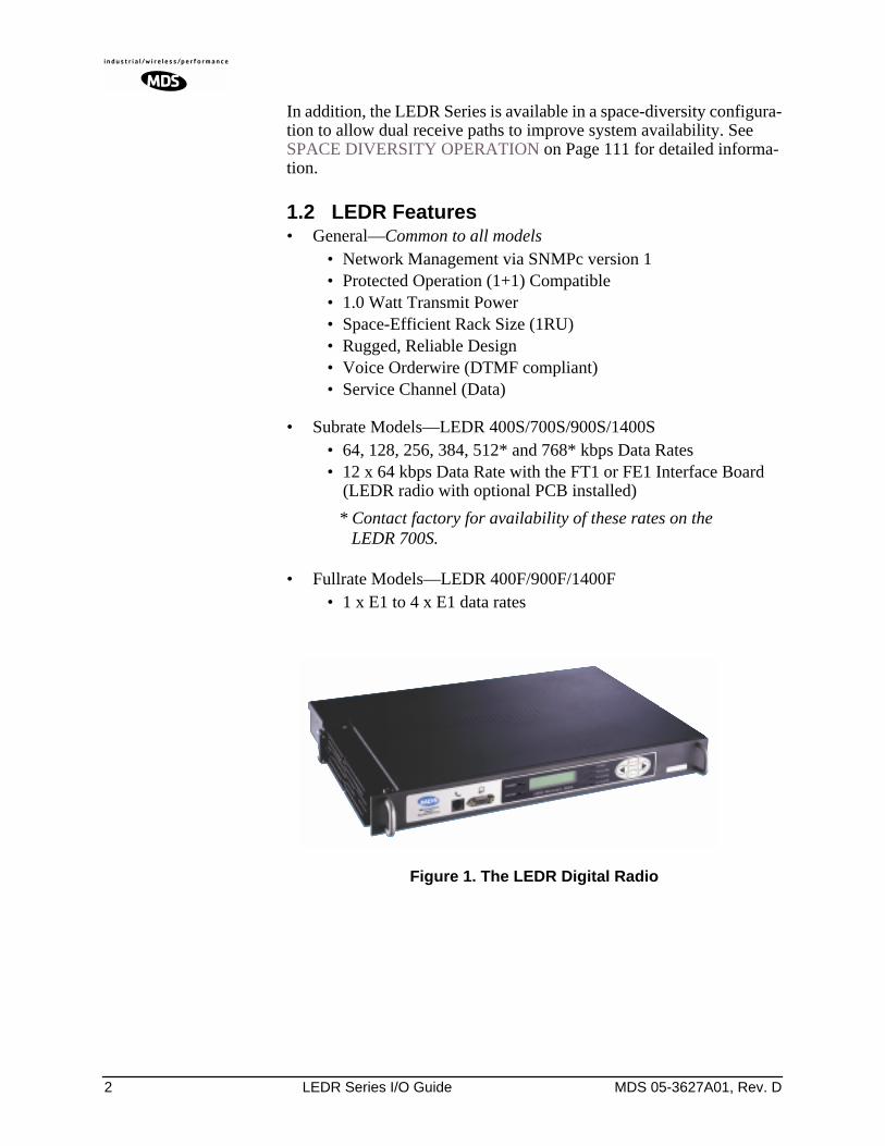
1.1 Product Description
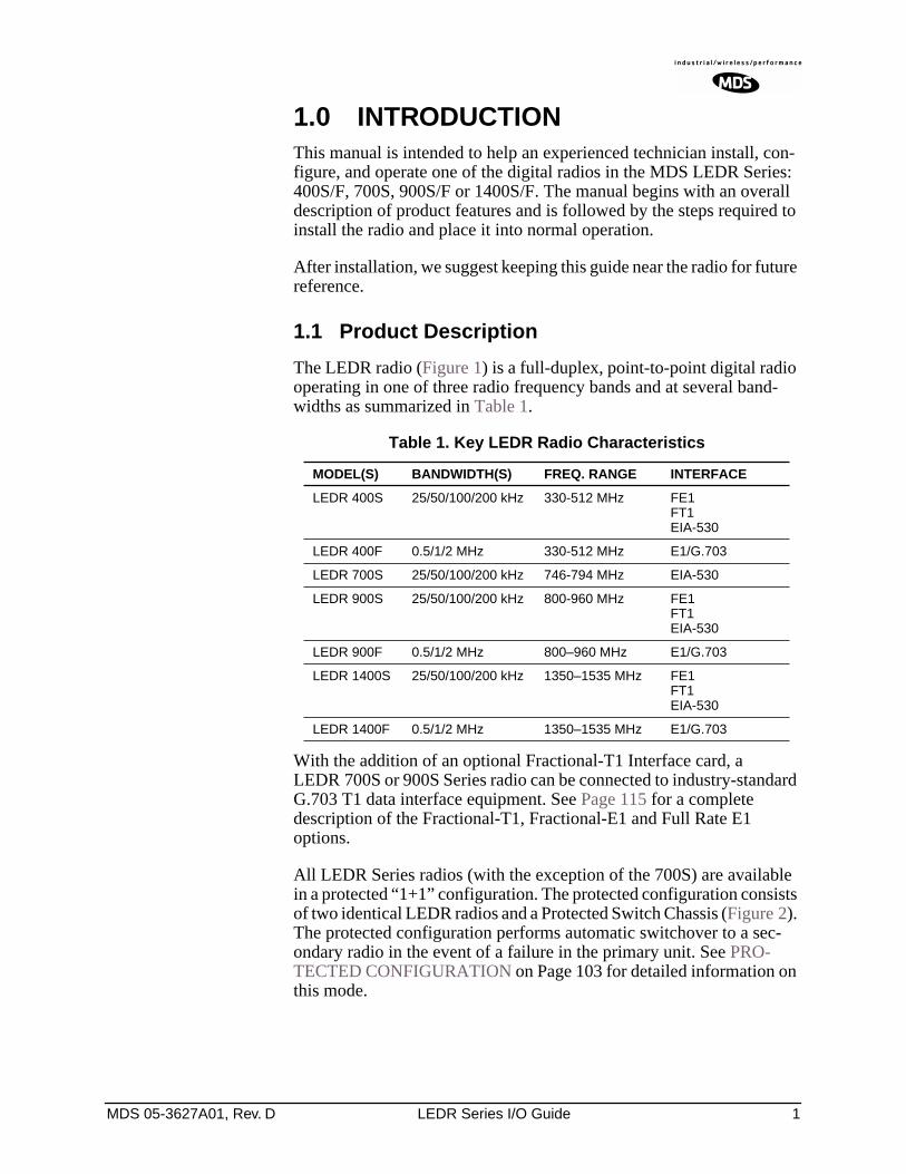
The LEDR radio (Figure 1) is a full-duplex, point-to-point digital radio operating in one of three radio frequency bands and at several band-widths as summarized in Table 1.
With the addition of an optional Fractional-T1 Interface card, a LEDR 700S or 900S Series radio can be connected to industry-standard G.703 T1 data interface equipment. See Page 115 for a complete description of the Fractional-T1, Fractional-E1 and Full Rate E1 options.
All LEDR Series radios (with the exception of the 700S) are available in a protected “1+1” configuration. The protected configuration consists of two identical LEDR radios and a Protected Switch Chassis (Figure 2). The protected configuration performs automatic switchover to a sec-ondary radio in the event of a failure in the primary unit. See PRO-TECTED CONFIGURATION on Page 103 for detailed information on this mode.
Table 1. Key LEDR Radio Characteristics
MODEL(S) BANDWIDTH(S) FREQ. RANGE INTERFACE
LEDR 400S 25/50/100/200 kHz 330-512 MHz FE1FT1EIA-530
LEDR 400F 0.5/1/2 MHz 330-512 MHz E1/G.703
LEDR 700S 25/50/100/200 kHz 746-794 MHz EIA-530
LEDR 900S 25/50/100/200 kHz 800-960 MHz FE1FT1EIA-530
LEDR 900F 0.5/1/2 MHz 800–960 MHz E1/G.703
LEDR 1400S 25/50/100/200 kHz 1350–1535 MHz FE1FT1EIA-530
LEDR 1400F 0.5/1/2 MHz 1350–1535 MHz E1/G.703
2 LEDR Series I/O Guide MDS 05-3627A01, Rev. D
In addition, the LEDR Series is available in a space-diversity configura-tion to allow dual receive paths to improve system availability. See SPACE DIVERSITY OPERATION on Page 111 for detailed informa-tion.
1.2 LEDR Features
• General—
Common to all models
• Network Management via SNMPc version 1• Protected Operation (1+1) Compatible• 1.0 Watt Transmit Power• Space-Efficient Rack Size (1RU)• Rugged, Reliable Design• Voice Orderwire (DTMF compliant)• Service Channel (Data)
• Subrate Models—LEDR 400S/700S/900S/1400S• 64, 128, 256, 384, 512* and 768* kbps Data Rates• 12 x 64 kbps Data Rate with the FT1 or FE1 Interface Board
(LEDR radio with optional PCB installed)
* Contact factory for availability of these rates on the LEDR 700S.
• Fullrate Models—LEDR 400F/900F/1400F• 1 x E1 to 4 x E1 data rates
Invisible place holder
Figure 1. The LEDR Digital Radio
MDS 05-3627A01, Rev. D LEDR Series I/O Guide 3
1.3 Typical Applications
• Point-to-point transmission applications• Cost-effective, “thin route” applications• Long haul telecommunications links• Cellular backhaul• Last-mile links• Trunked radio links• SCADA systems
1.4 Protected Configuration
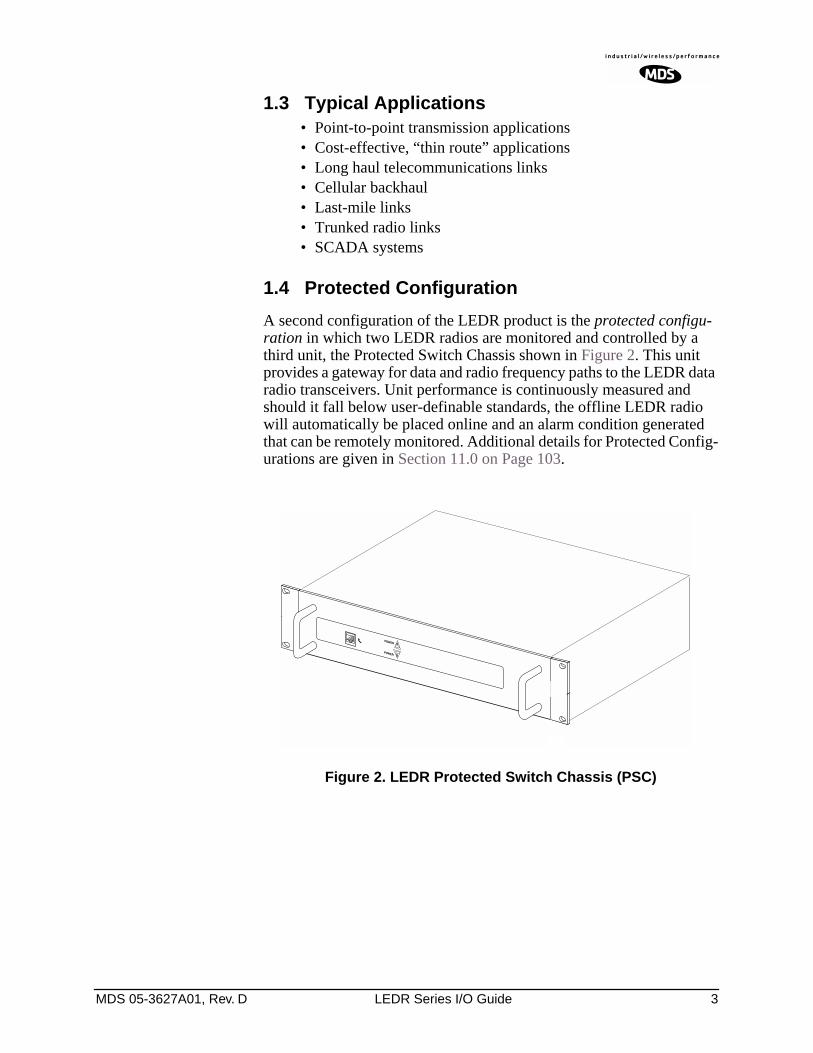
A second configuration of the LEDR product is the
protected configu-ration
in which two LEDR radios are monitored and controlled by a third unit, the Protected Switch Chassis shown in Figure 2. This unit provides a gateway for data and radio frequency paths to the LEDR data radio transceivers. Unit performance is continuously measured and should it fall below user-definable standards, the offline LEDR radio will automatically be placed online and an alarm condition generated that can be remotely monitored. Additional details for Protected Config-urations are given in Section 11.0 on Page 103.
Invisible place holder
Figure 2. LEDR Protected Switch Chassis (PSC)
4 LEDR Series I/O Guide MDS 05-3627A01, Rev. D
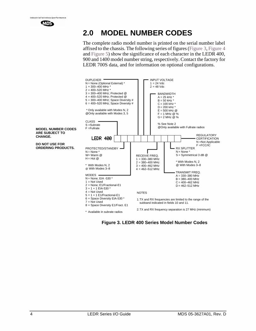
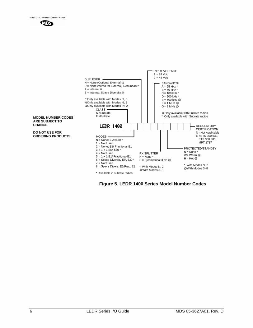
2.0 MODEL NUMBER CODES
The complete radio model number is printed on the serial number label affixed to the chassis. The following series of figures (Figure 3, Figure 4 and Figure 5) show the significance of each character in the LEDR 400, 900 and 1400 model number string, respectively. Contact the factory for LEDR 700S data, and for information on optional configurations.
Invisible place holder
Figure 3. LEDR 400 Series Model Number Codes
MODEL NUMBER CODES ARE SUBJECT TO CHANGE.
DO NOT USE FOR ORDERING PRODUCTS.
MODESN = None; EIA -530 *1 = Not Used2 = None; E1/Fractional-E13 = 1 + 1 EIA-530 *4 = Not Used5 = 1 + 1 E1/Fractional-E16 = Space Diversity EIA-530 *7 = Not Used8 = Space Diversity E1/Fract. E1
* Available in subrate radios
PROTECTED/STANDBYN = None *W= Warm @H = Hot @
* With Modes N, 2@ With Modes 3–8
LLLLEEEEDDDDRRRR 444400000000
CLASSS =SubrateF =Fullrate
DUPLEXERN = None (Optional External) *1 = 300–400 MHz *2 = 400–520 MHz *3 = 300–400 MHz; Protected @4 = 400–520 MHz; Protected @5 = 300–400 MHz; Space Diversity #6 = 400–520 MHz; Space Diversity #
* Only available with Modes N, 2@Only available with Modes 3, 5
BANDWIDTHA = 25 kHz *B = 50 kHz *C = 100 kHz *D = 200 kHz *E = 500 kHz @F = 1 MHz @ %G= 2 MHz @ %
% See Note 2@Only available with Fullrate radios
NOTES
1.TX and RX frequencies are limited to the range of the subband indicated in fields 10 and 11.
2.TX and RX frequency separation is 27 MHz (minimum)
TRANSMIT FREQ.A = 330–380 MHzB = 380–400 MHzC = 400–462 MHzD = 462–512 MHz
REGULATORY CERTIFICATIONN =Not ApplicableF =FCC/IC
RX SPLITTERN = None *S = Symmetrical 3 dB @
* With Modes N, 2@ With Modes 3–8
INPUT VOLTAGE1 = 24 Vdc2 = 48 Vdc
RECEIVE FREQ.1 = 330–380 MHz2 = 380–400 MHz3 = 400–462 MHz4 = 462–512 MHz
MDS 05-3627A01, Rev. D LEDR Series I/O Guide 5
Invisible place holder
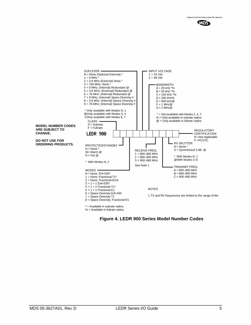
Figure 4. LEDR 900 Series Model Number Codes
MODEL NUMBER CODES ARE SUBJECT TO CHANGE.
DO NOT USE FOR ORDERING PRODUCTS.
MODESN = None; EIA-530*1 = None; Fractional-T1*2 = None; Fractional-E1%3 = 1 + 1 EIA=530*4 = 1 + 1 Fractional-T1*5 = 1 + 1 Fractional-E16 = Space Diversity EIA-5307 = Space Diversity T18 = Space Diversity; Fractional-E1
* = Available in subrate radios% = Available in fullrate radios
PROTECTED/STANDBYN = None *W= Warm @H = Hot @
* With Modes N, 2
LLLLEEEEDDDDRRRR 999900000000
DUPLEXERN = None (Optional External) *1 = 9 MHz *2 = 3.6 MHz (External) None *3 = 760 MHz; None *4 = 9 MHz; (Internal) Redundant @5 = 3.6 MHz; (External) Redundant @6 = 76 MHz; (Internal) Redundant @7 = 9 MHz; (Internal) Space Diversity #8 = 3.6 Mhz; (Internal) Space Diversity #9 = 76 MHz; (Internal) Space Diversity #
* Only available with Modes N, 1@Only available with Modes 3, 4 #Only available with Modes 6, 7
BANDWIDTHA = 25 kHz *%B = 50 kHz *%C = 100 kHz *%D = 200 kHz%E = 500 kHz@F = 1 MHz@G= 2 MHz@
* = Not available with Modes 1, 4, 7% = Only available in subrate radios@ = Only available in fullrate radios
NOTES
1.TX and RX frequencies are limited to the range of the
TRANSMIT FREQ.A = 800–860 MHzB = 860–900 MHzC = 900–960 MHz
REGULATORY CERTIFICATIONN =Not ApplicableF =FCC/IC
RX SPLITTERN = None *S = Symmetrical 3 dB @
* With Modes N, 1@With Modes 3–8
INPUT VOLTAGE1 = 24 Vdc2 = 48 Vdc
RECEIVE FREQ.1 = 800–860 MHz2 = 860–900 MHz3 = 900–960 MHz
See Note 1
CLASSS = SubrateF = Fullrate
6 LEDR Series I/O Guide MDS 05-3627A01, Rev. D
Invisible place holder
Figure 5. LEDR 1400 Series Model Number Codes
MODEL NUMBER CODES ARE SUBJECT TO CHANGE.
DO NOT USE FOR ORDERING PRODUCTS.
DUPLEXERN = None (Optional External) &R = None (Wired for External) Redundant *1 = Internal &2 = Internal; Space Diversity %
* Only available with Modes 3, 5%Only available with Modes 6, 8 &Only available with Modes N, 2
MODESN = None; EIA=530 *1 = Not Used2 = None; E1/ Fractional-E13 = 1 + 1 EIA-530 *4 = Not Used5 = 1 + 1 E1/ Fractional-E16 = Space Diversity EIA-530 *7 = Not Used8 = Space Divers. E1/Frac. E1
* Available in subrate radios
CLASSS =SubrateF =Fullrate
BANDWIDTHA = 25 kHz *B = 50 kHz *C = 100 kHz *D = 200 kHz *E = 500 kHz @F = 1 MHz @G= 2 MHz @
@Only available with Fullrate radios* Only available with Subrate radios
REGULATORY CERTIFICATIONN =Not ApplicableE =ETS 300 630,
ETS 300 385,MPT 1717
RX SPLITTERN = None *S = Symmetrical 3 dB @
* With Modes N, 2@With Modes 3–8
INPUT VOLTAGE1 = 24 Vdc2 = 48 Vdc
LLLLEEEEDDDDRRRR 1111444400000000
PROTECTED/STANDBYN = None *W= Warm @H = Hot @
* With Modes N, 2@With Modes 3–8
MDS 05-3627A01, Rev. D LEDR Series I/O Guide 7
3.0 HARDWARE INSTALLATION AND BASIC INTERFACE REQUIREMENTS
3.1 Introduction
Installation of the LEDR radio transceiver is not difficult, but it does require some planning to ensure optimal efficiency and reliability. There are two major installation objectives; first, obtain good radio communi-cations between LEDR sites, and second, configure the data interface to complement your data equipment.
This section provides information to assist you in successfully com-pleting the first phase of installation. You will find tips for selecting an appropriate site, choosing antennas and feedlines, minimizing the chance of interference, and the basics of equipment installation. This material should be reviewed before beginning the radio hardware equip-ment installation.
When the radio installation is successfully complete, you will need to address the data interface and operational configuration of the LEDR radio. It is likely that the radio has been configured by the factory to meet your basic data interface requirements. Please review the factory documentation accompanying your shipment for the radios current con-figuration.
What ever your situation, it is recommended you review the material in the rest of the manual to gain insight to additional configuration options and user functions.
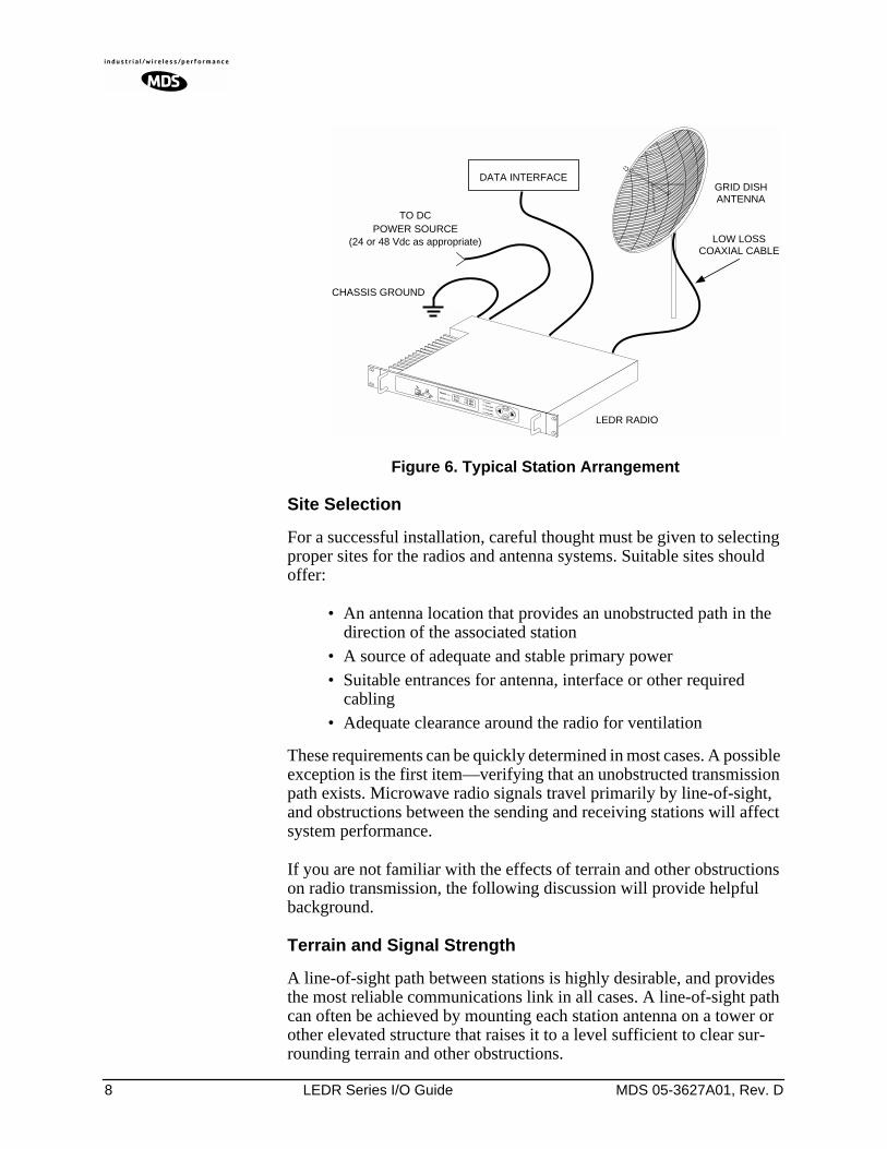
3.2 General Requirements
There are four main requirements for installing the radio transceiver—a suitable installation environment, adequate and stable primary power, a good antenna system, and the correct interface between the transceiver and the external data equipment. Figure 6 shows a typical station arrangement.
8 LEDR Series I/O Guide MDS 05-3627A01, Rev. D
Invisible place holder
Figure 6. Typical Station Arrangement
Site Selection
For a successful installation, careful thought must be given to selecting proper sites for the radios and antenna systems. Suitable sites should offer:
• An antenna location that provides an unobstructed path in the direction of the associated station
• A source of adequate and stable primary power• Suitable entrances for antenna, interface or other required
cabling• Adequate clearance around the radio for ventilation
These requirements can be quickly determined in most cases. A possible exception is the first item—verifying that an unobstructed transmission path exists. Microwave radio signals travel primarily by line-of-sight, and obstructions between the sending and receiving stations will affect system performance.
If you are not familiar with the effects of terrain and other obstructions on radio transmission, the following discussion will provide helpful background.
Terrain and Signal Strength
A line-of-sight path between stations is highly desirable, and provides the most reliable communications link in all cases. A line-of-sight path can often be achieved by mounting each station antenna on a tower or other elevated structure that raises it to a level sufficient to clear sur-rounding terrain and other obstructions.
GRID DISHANTENNA
LOW LOSSCOAXIAL CABLE
TO DCPOWER SOURCE
(24 or 48 Vdc as appropriate)
DATA INTERFACE
LEDR RADIO
CHASSIS GROUND
MDS 05-3627A01, Rev. D LEDR Series I/O Guide 9
The requirement for a clear transmission path depends upon the distance to be covered by the system. If the system is to cover only a limited dis-tance, say 5 km (3.1 miles), then some obstructions in the transmission path may be tolerable. For longer-range systems, any obstruction could compromise the performance of the system, or block transmission entirely.
The signal strength at the receiver must exceed the receiver sensitivity by an amount known as the fade margin to provide reliable operation under various conditions.
Detailed information on path planning should be reviewed before begin-ning an installation. Computer software is also available for this purpose that can greatly simplify the steps involved in planning a path.
Microwave Data Systems offers path analysis (for paths in the USA) as an engineering service. Contact the factory for additional information.
On-the-Air Test
If you’ve analyzed the proposed transmission path and feel that it is acceptable, an on-the-air test of the equipment and path should be con-ducted. This not only verifies the path study results, but allows you to see firsthand the factors involved at each installation site.
The test can be performed by installing a radio at each end of the pro-posed link and checking the Received Signal Strength Indication (RSSI) value reported at the front panel LCD screen of each radio. If adequate signal strength cannot be obtained, it may be necessary to mount the sta-tion antennas higher, use higher gain antennas, or select a different site for one or both stations.
A Word About Interference
Interference is possible in any radio system. However, since the LEDR radio is designed for use in a licensed system, interference is less likely because frequency allocations are normally coordinated with consider-ation given to geographic location and existing operating frequencies.
The risk of interference can be further reduced through prudent system design and configuration. Allow adequate separation between frequen-cies and radio systems.
C/I Curves A carrier to interference (C/I) curve can help in frequency and space coordination. The information in this curve can aid greatly in helping plan geographic locations and frequency usage for radio systems. Con-tact the factory for additional information on carrier to interference curves. A white paper (publication no. 05-3638A01) on the subject is available from MDS at www.microwavedata.com. Search for the term “LEDR” under the manuals download area to see this, and all other pub-lications pertaining to the LEDR series.
10 LEDR Series I/O Guide MDS 05-3627A01, Rev. D
Keep the following points in mind when setting up your point-to-point system:
1. Systems installed in lightly populated areas are least likely to encounter interference; those in urban and suburban environments are more likely to be affected by other devices operating in the radio’s frequency band and adjacent services.
2. Directional antennas must be used at each end of a point-to-point link. They confine the transmission and reception pattern to a com-paratively narrow beam, which minimizes interference to and from stations located outside the pattern. The larger the antenna, the more focused the transmission and reception pattern and the higher the gain.
3. If interference is suspected from another system, it may be helpful to use antenna polarization that is opposite to the interfering sys-tem’s antennas. An additional 20 dB (or more) of attenuation to interference can be achieved by using opposite antenna polarization. Refer to the antenna manufacturer’s instructions for details on changing polarization.
3.3 Antenna and Feedline Selection
Antennas
The antenna system is perhaps the most crucial part of the system design. An antenna system that uses poor quality feedline, or is improp-erly aligned with the companion site, will result in poor performance, or no communication at all.
A directional antenna must be used for point-to-point systems to mini-mize interference both to and from nearby systems. In general, cylin-drical or dish type antennas with a parabolic reflector must be used. Yagi or corner reflector types may be acceptable in some applications. Check government regulations for your region.
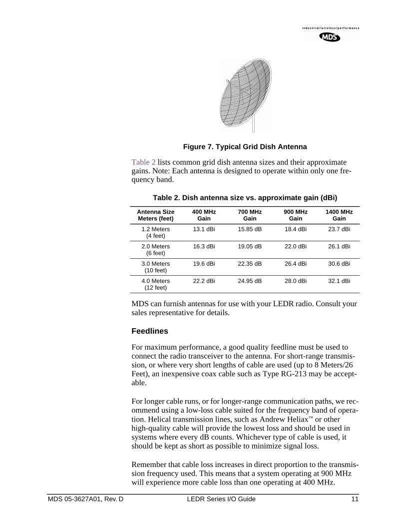
The exact style of antenna used depends on the size and layout of a system. In most cases, a directional “dish” type of antenna is used with the radio (Figure 7). Dish antennas maximize transmission efficiency and restrict the radiation pattern to the desired transmission path.
MDS 05-3627A01, Rev. D LEDR Series I/O Guide 11
Invisible place holder
Figure 7. Typical Grid Dish Antenna
Table 2 lists common grid dish antenna sizes and their approximate gains. Note: Each antenna is designed to operate within only one fre-quency band.
MDS can furnish antennas for use with your LEDR radio. Consult your sales representative for details.
Feedlines
For maximum performance, a good quality feedline must be used to connect the radio transceiver to the antenna. For short-range transmis-sion, or where very short lengths of cable are used (up to 8 Meters/26 Feet), an inexpensive coax cable such as Type RG-213 may be accept-able.
For longer cable runs, or for longer-range communication paths, we rec-ommend using a low-loss cable suited for the frequency band of opera-tion. Helical transmission lines, such as Andrew Heliax™ or other high-quality cable will provide the lowest loss and should be used in systems where every dB counts. Whichever type of cable is used, it should be kept as short as possible to minimize signal loss.
Remember that cable loss increases in direct proportion to the transmis-sion frequency used. This means that a system operating at 900 MHz will experience more cable loss than one operating at 400 MHz.
Table 2. Dish antenna size vs. approximate gain (dBi)
Antenna SizeMeters (feet)
400 MHzGain
700 MHzGain
900 MHzGain
1400 MHzGain
1.2 Meters(4 feet)
13.1 dBi 15.85 dB 18.4 dBi 23.7 dBi
2.0 Meters(6 feet)
16.3 dBi 19.05 dB 22.0 dBi 26.1 dBi
3.0 Meters(10 feet)
19.6 dBi 22.35 dB 26.4 dBi 30.6 dBi
4.0 Meters(12 feet)
22.2 dBi 24.95 dB 28.0 dBi 32.1 dBi
12 LEDR Series I/O Guide MDS 05-3627A01, Rev. D
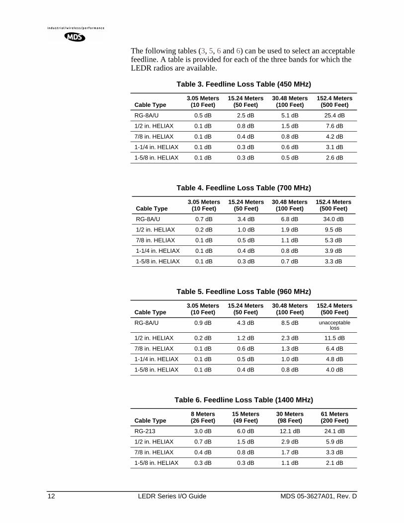
The following tables (3, 5, 6 and 6) can be used to select an acceptable feedline. A table is provided for each of the three bands for which the LEDR radios are available.
Table 3. Feedline Loss Table (450 MHz)
Cable Type 3.05 Meters
(10 Feet)15.24 Meters
(50 Feet)30.48 Meters
(100 Feet)152.4 Meters
(500 Feet)
RG-8A/U 0.5 dB 2.5 dB 5.1 dB 25.4 dB
1/2 in. HELIAX 0.1 dB 0.8 dB 1.5 dB 7.6 dB
7/8 in. HELIAX 0.1 dB 0.4 dB 0.8 dB 4.2 dB
1-1/4 in. HELIAX 0.1 dB 0.3 dB 0.6 dB 3.1 dB
1-5/8 in. HELIAX 0.1 dB 0.3 dB 0.5 dB 2.6 dB
Table 4. Feedline Loss Table (700 MHz)
Cable Type 3.05 Meters
(10 Feet)15.24 Meters
(50 Feet)30.48 Meters
(100 Feet)152.4 Meters
(500 Feet)
RG-8A/U 0.7 dB 3.4 dB 6.8 dB 34.0 dB
1/2 in. HELIAX 0.2 dB 1.0 dB 1.9 dB 9.5 dB
7/8 in. HELIAX 0.1 dB 0.5 dB 1.1 dB 5.3 dB
1-1/4 in. HELIAX 0.1 dB 0.4 dB 0.8 dB 3.9 dB
1-5/8 in. HELIAX 0.1 dB 0.3 dB 0.7 dB 3.3 dB
Table 5. Feedline Loss Table (960 MHz)
Cable Type 3.05 Meters
(10 Feet)15.24 Meters
(50 Feet)30.48 Meters
(100 Feet)152.4 Meters
(500 Feet)
RG-8A/U 0.9 dB 4.3 dB 8.5 dB unacceptable loss
1/2 in. HELIAX 0.2 dB 1.2 dB 2.3 dB 11.5 dB
7/8 in. HELIAX 0.1 dB 0.6 dB 1.3 dB 6.4 dB
1-1/4 in. HELIAX 0.1 dB 0.5 dB 1.0 dB 4.8 dB
1-5/8 in. HELIAX 0.1 dB 0.4 dB 0.8 dB 4.0 dB
Table 6. Feedline Loss Table (1400 MHz)
Cable Type 8 Meters(26 Feet)
15 Meters(49 Feet)
30 Meters(98 Feet)
61 Meters(200 Feet)
RG-213 3.0 dB 6.0 dB 12.1 dB 24.1 dB
1/2 in. HELIAX 0.7 dB 1.5 dB 2.9 dB 5.9 dB
7/8 in. HELIAX 0.4 dB 0.8 dB 1.7 dB 3.3 dB
1-5/8 in. HELIAX 0.3 dB 0.3 dB 1.1 dB 2.1 dB
MDS 05-3627A01, Rev. D LEDR Series I/O Guide 13
3.4 Radio Mounting
The radio can be mounted either in a 19-inch equipment rack or on a table top. It should be located in a relatively clean, dust-free environ-ment that allows easy access to the rear panel connectors as well as front panel controls and indicators. Air must be allowed to pass freely over the ventilation holes and heat sink on the side panel.
The dimensions of LEDR Series radios are:
• 305 mm (12 in) deep • 426 mm (16.75 in) wide—Excluding rack mounting brackets• 45 mm (1.75 in) high—1RU
Maximizing RSSI
For newly installed systems, one of the first tasks is to orient the station antenna for a maximum Received Signal Strength Indication (RSSI) as shown on the LCD screen. See “Performance” on Page 40 for details. A maximum RSSI ensures the antenna is properly aimed at the associated station. Move the antenna slowly while an assistant observes the RSSI display for a maximum reading. There may be a time delay between moving the antenna and updating of the RSSI display. Be sure to allow adequate time between antenna movements and observations.
Attaching the Rack Mounting Brackets
The radio is normally shipped with the rack mounting brackets unin-stalled. To attach them, select the desired mounting position on the sides of the chassis. (The brackets may be mounted in one of two locations—flush with the front panel, or near the middle of the chassis.)
NOTE: Both short and long screws are provided with the brackets. Usethe long screws for the heatsink (left) side of the chassis andthe short screws for the right side of the chassis. Tighten thescrews securely.
14 LEDR Series I/O Guide MDS 05-3627A01, Rev. D
3.5 Front Panel
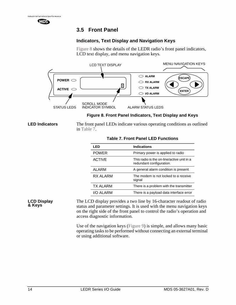
Indicators, Text Display and Navigation Keys
Figure 8 shows the details of the LEDR radio’s front panel indicators, LCD text display, and menu navigation keys.
Figure 8. Front Panel Indicators, Text Display and Keys
LED Indicators The front panel LEDs indicate various operating conditions as outlined in Table 7.
LCD Display& Keys
The LCD display provides a two line by 16-character readout of radio status and parameter settings. It is used with the menu navigation keys on the right side of the front panel to control the radio’s operation and access diagnostic information.
Use of the navigation keys (Figure 9) is simple, and allows many basic operating tasks to be performed without connecting an external terminal or using additional software.
MENU NAVIGATION KEYS
ALARM STATUS LEDS
LCD TEXT DISPLAY
SCROLL MODEINDICATOR SYMBOLSTATUS LEDS
Table 7. Front Panel LED Functions
LED Indications
POWER Primary power is applied to radio
ACTIVE This radio is the on-line/active unit in a redundant configuration.
ALARM A general alarm condition is present
RX ALARM The modem is not locked to a receive signal
TX ALARM There is a problem with the transmitter
I/O ALARM There is a payload data interface error
MDS 05-3627A01, Rev. D LEDR Series I/O Guide 15
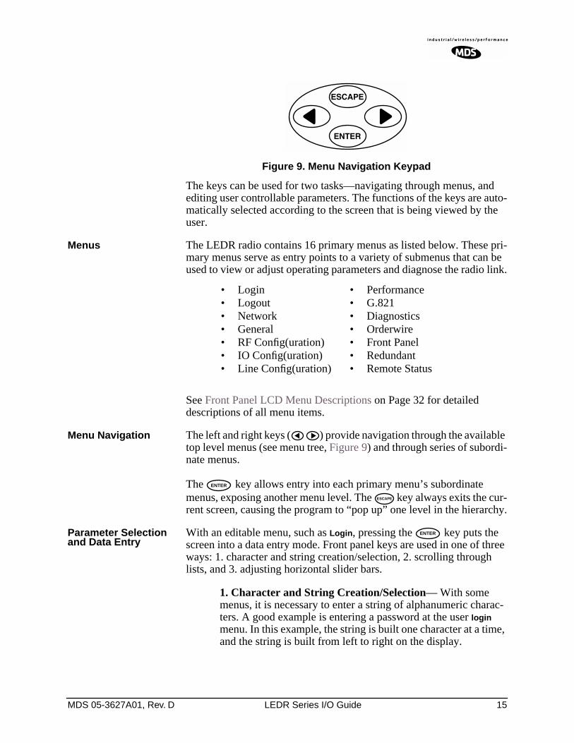
Invisible place holder
Figure 9. Menu Navigation Keypad
The keys can be used for two tasks—navigating through menus, and editing user controllable parameters. The functions of the keys are auto-matically selected according to the screen that is being viewed by the user.
Menus The LEDR radio contains 16 primary menus as listed below. These pri-mary menus serve as entry points to a variety of submenus that can be used to view or adjust operating parameters and diagnose the radio link.
See Front Panel LCD Menu Descriptions on Page 32 for detailed descriptions of all menu items.
Menu Navigation The left and right keys ( ) provide navigation through the available top level menus (see menu tree, Figure 9) and through series of subordi-nate menus.
The key allows entry into each primary menu’s subordinate menus, exposing another menu level. The key always exits the cur-rent screen, causing the program to “pop up” one level in the hierarchy.
Parameter Selectionand Data Entry
With an editable menu, such as Login, pressing the key puts the screen into a data entry mode. Front panel keys are used in one of three ways: 1. character and string creation/selection, 2. scrolling through lists, and 3. adjusting horizontal slider bars.
1. Character and String Creation/Selection— With some menus, it is necessary to enter a string of alphanumeric charac-ters. A good example is entering a password at the user login menu. In this example, the string is built one character at a time, and the string is built from left to right on the display.
• Login• Logout• Network• General• RF Config(uration)• IO Config(uration)• Line Config(uration)
• Performance• G.821• Diagnostics• Orderwire• Front Panel• Redundant• Remote Status
ENTER
ESCAPE
ENTER
16 LEDR Series I/O Guide MDS 05-3627A01, Rev. D
The left and right arrow keys move the cursor in the corre-sponding direction. When the cursor is below the character you wish to change, press . The arrow keys are then used to step though the character set, beginning with numbers, then upper-case letters and finally lowercase letters. Each time you press one of the arrow keys, the display will step to the next character. If you press and hold the arrow key for several seconds, the char-acters will scroll by very quickly.
After you have built the string of characters you need, press the key to save the string on the display and return to cursor
navigation mode. To save all changes you have made, place the cursor under the special carriage return symbol ( ) and press
. Pressing will revert the arrow keys to the cursor nav-igation mode. Pressing in cursor navigation mode cancels character edit mode without saving any changes.
2. Scrolling Lists/Values— Uses left and right keys ( ) to scroll through a list of choices or adjust a numeric value, such as PPPPoooowwwweeeerrrr OOOOuuuutttt. When you are in a menu with a series of fixed parame-ters, the vertical scroll character ( ) will appear while you are in the editing/selection mode. If you are asked to select or change more than one character, you will see a horizontal scroll symbol ( ) in the bottom right-hand corner of the display and a cursor will appear under the character being edited or changed.
When the desired parameter is in view, move the cursor to the right as far as it will go, until a carriage return symbol ( ) appears. Pressing the key will save the selection to its left, if your access privileges permit. Pressing cancels the selec-tion and exits without saving the change.
3. Slider Bar Adjustment—Some menus display a horizontal bar that changes its length to indicate the level for parameters that use relative values such as the Orderwire Volume and VOX threshold. (See Orderwire on Page 40.) Press the key to increase the value and the to lower the value. Press to save the current setting.
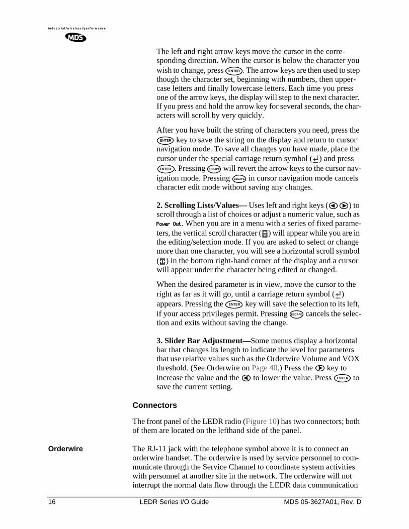
Connectors
The front panel of the LEDR radio (Figure 10) has two connectors; both of them are located on the lefthand side of the panel.
Orderwire The RJ-11 jack with the telephone symbol above it is to connect an orderwire handset. The orderwire is used by service personnel to com-municate through the Service Channel to coordinate system activities with personnel at another site in the network. The orderwire will not interrupt the normal data flow through the LEDR data communication
ENTER
ENTER
ENTER ESCAPE
ESCAPE
ENTER
ESCAPE
ENTER
MDS 05-3627A01, Rev. D LEDR Series I/O Guide 17
channel, however, it will reduce the throughput efficiency of any data communications on the Service Channel during periods of voice trans-mission. See “USING ORDERWIRE” on Page 99 for more informa-tion.
CONSOLE The second connector is a DB-9 type with a computer icon over it. Here is where you can connect a computer’s serial port for unit configuration, diagnostics and firmware upgrades to the radio.
Invisible place holder
Figure 10. LEDR Front Panel(All models Identical)
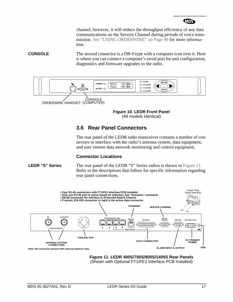
3.6 Rear Panel Connectors
The rear panel of the LEDR radio transceiver contains a number of con-nectors to interface with the radio’s antenna system, data equipment, and user remote data network monitoring and control equipment.
Connector Locations
LEDR “S” Series The rear panel of the LEDR “S” Series radios is shown in Figure 11. Refer to the descriptions that follow for specific information regarding rear panel connections.
Invisible place holder
Figure 11. LEDR 400S/700S/900S/1400S Rear Panels(Shown with Optional FT1/FE1 Interface PCB Installed)
CONSOLE(COMPUTER)ORDERWIRE HANDSET
Antenna/TX
External Duplexer
RXG.703/Expansion Data
EIA-530-AEthernetNMS
Data Interface
ServiceChannel Alarm I/O DC Power Input
Power PlugDetail (see text)
COOLING FAN
ETHERNET SERVICE CHANNEL
ALARM INPUT & OUTPUT
DC PRIMARYANTENNA SYSTEM
Note: RX Connector present with external duplexer only.
CONNECTORSPOWER
• Four RJ-45 connectors with FT1/FE1 Interface PCB installed• Only one RJ-45 port is active based on selection. See “linename” command.• DB-68 Connector for interface to Protected Switch Chassis• If vacant, EIA-530 connector to right is the active data connector.
GND
1 3 42
DATA CONNECTOR
18 LEDR Series I/O Guide MDS 05-3627A01, Rev. D
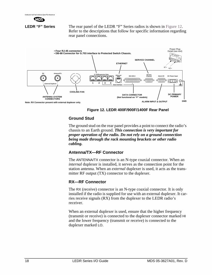
LEDR “F” Series The rear panel of the LEDR “F” Series radios is shown in Figure 12. Refer to the descriptions that follow for specific information regarding rear panel connections.
Invisible place holder
Figure 12. LEDR 400F/900F/1400F Rear Panel
Ground Stud
The ground stud on the rear panel provides a point to connect the radio’s chassis to an Earth ground. This connection is very important for proper operation of the radio. Do not rely on a ground connection being made through the rack mounting brackets or other radio cabling.
Antenna/TX—RF Connector
The ANTENNA/TX connector is an N-type coaxial connector. When an internal duplexer is installed, it serves as the connection point for the station antenna. When an external duplexer is used, it acts as the trans-mitter RF output (TX) connector to the duplexer.
RX—RF Connector
The RX (receive) connector is an N-type coaxial connector. It is only installed if the radio is supplied for use with an external duplexer. It car-ries receive signals (RX) from the duplexer to the LEDR radio’s receiver.
When an external duplexer is used, ensure that the higher frequency (transmit or receive) is connected to the duplexer connector marked HI and the lower frequency (transmit or receive) is connected to the duplexer marked LO.
Antenna/TX
External Duplexer
RXG.703/Expansion Data
EIA-530-AEthernetNMS
Data Interface
ServiceChannel Alarm I/O DC Power Input
Power PlugDetail (see text)
COOLING FAN
ETHERNET
SERVICE CHANNEL
ALARM INPUT & OUTPUT
DC PRIMARYANTENNA SYSTEM
Note: RX Connector present with external duplexer only.
CONNECTORSPOWER
• Four RJ-45 connectors• DB-68 Connector for G.703 interface to Protected Switch Chassis.
GND
DATA CONNECTOR(Not functional on “F” models)
1 3 42
MDS 05-3627A01, Rev. D LEDR Series I/O Guide 19
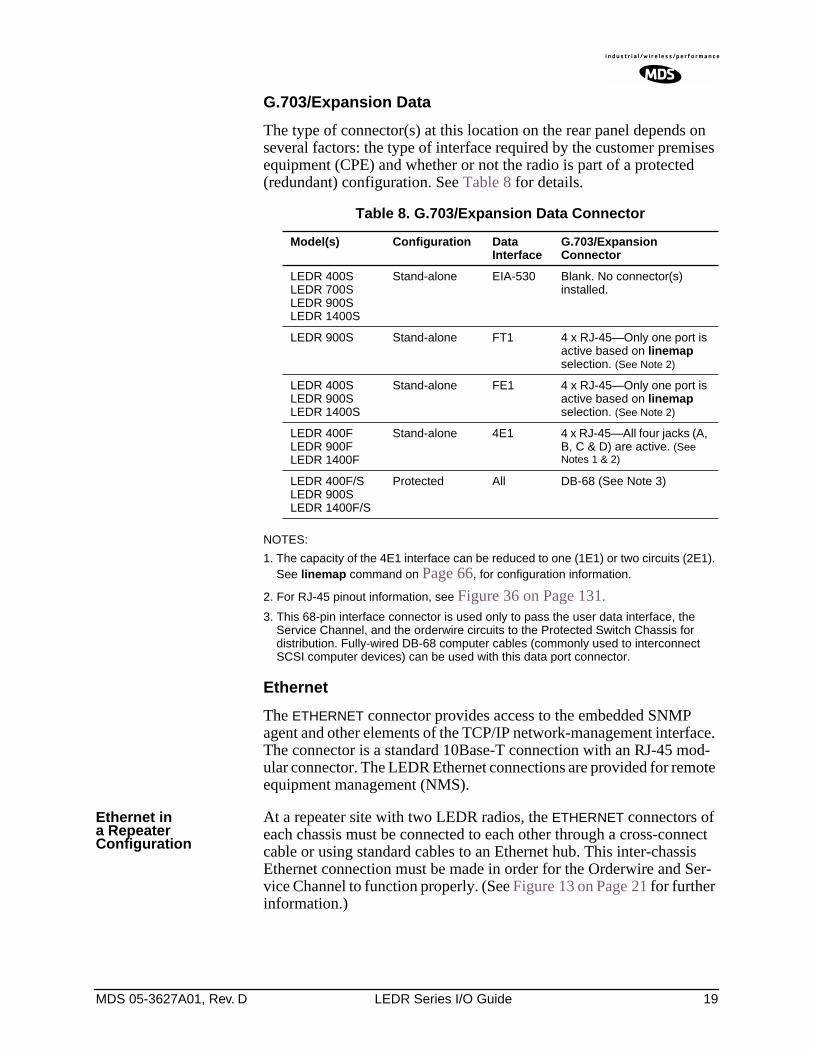
G.703/Expansion Data
The type of connector(s) at this location on the rear panel depends on several factors: the type of interface required by the customer premises equipment (CPE) and whether or not the radio is part of a protected (redundant) configuration. See Table 8 for details.
NOTES:
1. The capacity of the 4E1 interface can be reduced to one (1E1) or two circuits (2E1). See linemap command on Page 66, for configuration information.
2. For RJ-45 pinout information, see Figure 36 on Page 131.
3. This 68-pin interface connector is used only to pass the user data interface, the Service Channel, and the orderwire circuits to the Protected Switch Chassis for distribution. Fully-wired DB-68 computer cables (commonly used to interconnect SCSI computer devices) can be used with this data port connector.
Ethernet
The ETHERNET connector provides access to the embedded SNMP agent and other elements of the TCP/IP network-management interface. The connector is a standard 10Base-T connection with an RJ-45 mod-ular connector. The LEDR Ethernet connections are provided for remote equipment management (NMS).
Ethernet in a Repeater Configuration
At a repeater site with two LEDR radios, the ETHERNET connectors of each chassis must be connected to each other through a cross-connect cable or using standard cables to an Ethernet hub. This inter-chassis Ethernet connection must be made in order for the Orderwire and Ser-vice Channel to function properly. (See Figure 13 on Page 21 for further information.)
Table 8. G.703/Expansion Data Connector
Model(s) Configuration Data Interface
G.703/ExpansionConnector
LEDR 400SLEDR 700SLEDR 900SLEDR 1400S
Stand-alone EIA-530 Blank. No connector(s) installed.
LEDR 900S Stand-alone FT1 4 x RJ-45—Only one port is active based on linemap selection. (See Note 2)
LEDR 400SLEDR 900SLEDR 1400S
Stand-alone FE1 4 x RJ-45—Only one port is active based on linemap selection. (See Note 2)
LEDR 400FLEDR 900FLEDR 1400F
Stand-alone 4E1 4 x RJ-45—All four jacks (A, B, C & D) are active. (See Notes 1 & 2)
LEDR 400F/SLEDR 900SLEDR 1400F/S
Protected All DB-68 (See Note 3)
20 LEDR Series I/O Guide MDS 05-3627A01, Rev. D
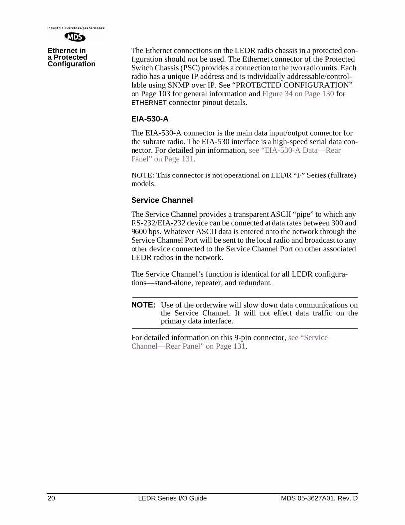
Ethernet in a Protected Configuration
The Ethernet connections on the LEDR radio chassis in a protected con-figuration should not be used. The Ethernet connector of the Protected Switch Chassis (PSC) provides a connection to the two radio units. Each radio has a unique IP address and is individually addressable/control-lable using SNMP over IP. See “PROTECTED CONFIGURATION” on Page 103 for general information and Figure 34 on Page 130 for ETHERNET connector pinout details.
EIA-530-A
The EIA-530-A connector is the main data input/output connector for the subrate radio. The EIA-530 interface is a high-speed serial data con-nector. For detailed pin information, see “EIA-530-A Data—Rear Panel” on Page 131.
NOTE: This connector is not operational on LEDR “F” Series (fullrate) models.
Service Channel
The Service Channel provides a transparent ASCII “pipe” to which any RS-232/EIA-232 device can be connected at data rates between 300 and 9600 bps. Whatever ASCII data is entered onto the network through the Service Channel Port will be sent to the local radio and broadcast to any other device connected to the Service Channel Port on other associated LEDR radios in the network.
The Service Channel’s function is identical for all LEDR configura-tions—stand-alone, repeater, and redundant.
NOTE: Use of the orderwire will slow down data communications onthe Service Channel. It will not effect data traffic on theprimary data interface.
For detailed information on this 9-pin connector, see “Service Channel—Rear Panel” on Page 131.
MDS 05-3627A01, Rev. D LEDR Series I/O Guide 21
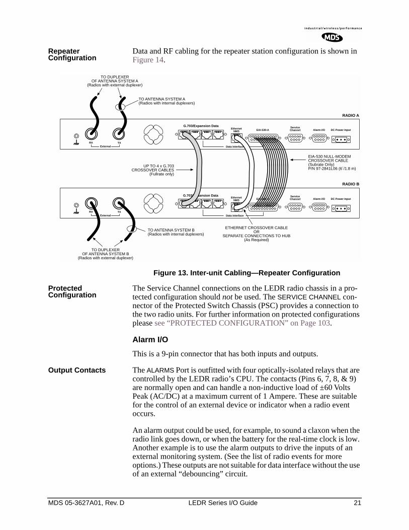
Repeater Configuration
Data and RF cabling for the repeater station configuration is shown in Figure 14.
Figure 13. Inter-unit Cabling—Repeater Configuration
Protected Configuration
The Service Channel connections on the LEDR radio chassis in a pro-tected configuration should not be used. The SERVICE CHANNEL con-nector of the Protected Switch Chassis (PSC) provides a connection to the two radio units. For further information on protected configurations please see “PROTECTED CONFIGURATION” on Page 103.
Alarm I/O
This is a 9-pin connector that has both inputs and outputs.
Output Contacts The ALARMS Port is outfitted with four optically-isolated relays that are controlled by the LEDR radio’s CPU. The contacts (Pins 6, 7, 8, & 9) are normally open and can handle a non-inductive load of ±60 Volts Peak (AC/DC) at a maximum current of 1 Ampere. These are suitable for the control of an external device or indicator when a radio event occurs.
An alarm output could be used, for example, to sound a claxon when the radio link goes down, or when the battery for the real-time clock is low. Another example is to use the alarm outputs to drive the inputs of an external monitoring system. (See the list of radio events for more options.) These outputs are not suitable for data interface without the use of an external “debouncing” circuit.
TXExternal Data Interface
EIA-530-AEthernetNMS
ServiceChannel Alarm I/O DC Power Input
EIA-530-AEthernetNMS
Data Interface
ServiceChannel Alarm I/O DC Power Input
TO ANTENNA SYSTEM A(Radios with internal duplexers)
RX
UP TO 4 x G.703CROSSOVER CABLES
(Fullrate only)
TXExternal
RX
G.703/Expansion Data
G.703/Expansion Data
RADIO A
RADIO B
EIA-530 NULL-MODEMCROSSOVER CABLE(Subrate Only)P/N 97-2841L06 (6´/1.8 m)
ETHERNET CROSSOVER CABLEOR
SEPARATE CONNECTIONS TO HUB(As Required)
TO DUPLEXEROF ANTENNA SYSTEM A
(Radios with external duplexer)
TO DUPLEXEROF ANTENNA SYSTEM B
(Radios with external duplexer)
TO ANTENNA SYSTEM B(Radios with internal duplexers)
22 LEDR Series I/O Guide MDS 05-3627A01, Rev. D
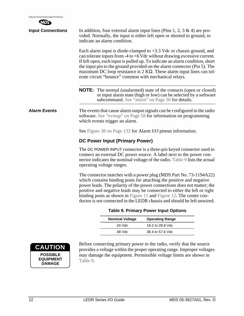
Input Connections In addition, four external alarm input lines (Pins 1, 2, 3 & 4) are pro-vided. Normally, the input is either left open or shorted to ground, to indicate an alarm condition.
Each alarm input is diode-clamped to +3.3 Vdc or chassis ground, and can tolerate inputs from -4 to +6 Vdc without drawing excessive current. If left open, each input is pulled up. To indicate an alarm condition, short the input pin to the ground provided on the alarm connector (Pin 5). The maximum DC loop resistance is 2 KΩ. These alarm input lines can tol-erate circuit “bounce” common with mechanical relays.
NOTE: The normal (unalarmed) state of the contacts (open or closed)or input alarm state (high or low) can be selected by a softwaresubcommand. See “alarm” on Page 50 for details.
Alarm Events The events that cause alarm output signals can be configured in the radio software. See “evmap” on Page 58 for information on programming which events trigger an alarm.
See Figure 38 on Page 132 for Alarm I/O pinout information.
DC Power Input (Primary Power)
The DC POWER INPUT connector is a three-pin keyed connector used to connect an external DC power source. A label next to the power con-nector indicates the nominal voltage of the radio. Table 9 lists the actual operating voltage ranges.
The connector matches with a power plug (MDS Part No. 73-1194A22) which contains binding posts for attaching the positive and negative power leads. The polarity of the power connections does not matter; the positive and negative leads may be connected to either the left or right binding posts as shown in Figure 11 and Figure 12. The center con-ductor is not connected in the LEDR chassis and should be left unwired.
Before connecting primary power to the radio, verify that the source provides a voltage within the proper operating range. Improper voltages may damage the equipment. Permissible voltage limits are shown in Table 9.
Table 9. Primary Power Input Options
Nominal Voltage Operating Range
24 Vdc 19.2 to 28.8 Vdc
48 Vdc 38.4 to 57.6 Vdc
CAUTIONPPPPOOOOSSSSSSSSIIIIBBBBLLLLEEEE
EEEEQQQQUUUUIIIIPPPPMMMMEEEENNNNTTTT
DDDDAAAAMMMMAAAAGGGGEEEE
CAUTIONPOSSIBLE
EQUIPMENTDAMAGE
MDS 05-3627A01, Rev. D LEDR Series I/O Guide 23
Protected Configuration Connections
There are several connections between the LEDR radio chassis and the Protected Switch Chassis. They include the primary data interface, RF, Ethernet, orderwire and Service Channel. Details on cabling and other items relating to the protected (redundant) configuration appear in PRO-TECTED CONFIGURATION on Page 103.
3.7 Bandwidths, Data Rates and Modulation Types
The hardware in the LEDR chassis is configured at the factory for a spe-cific bandwidth. However, the modulation type and data rate can be changed as long as the bandwidth is sufficient to support the modulation type and data rate. (If you need to change your radio’s bandwidth, please see “INCREASE BANDWIDTH BY CHANGING TRANS-MITTER AND RECEIVER FILTERS” on Page 120 for details.)
Use of the modem command (Page 71) and configuration ([argument]) code automatically sets the combination of data rate, bandwidth and modulation type if the radio is capable of supporting it
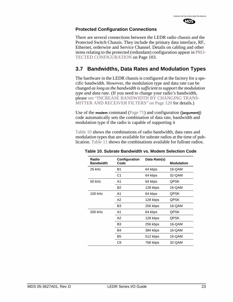
Table 10 shows the combinations of radio bandwidth, data rates and modulation types that are available for subrate radios at the time of pub-lication. Table 11 shows the combinations available for fullrate radios.
Table 10. Subrate Bandwidth vs. Modem Selection Code
Radio Bandwidth
Configuration Code
Data Rate(s)Modulation
25 kHz B1 64 kbps 16-QAM
C1 64 kbps 32-QAM
50 kHz A1 64 kbps QPSK
B2 128 kbps 16-QAM
100 kHz A1 64 kbps QPSK
A2 128 kbps QPSK
B3 256 kbps 16-QAM
200 kHz A1 64 kbps QPSK
A2 128 kbps QPSK
B3 256 kbps 16-QAM
B4 384 kbps 16-QAM
B5 512 kbps 16-QAM
C6 768 kbps 32-QAM
24 LEDR Series I/O Guide MDS 05-3627A01, Rev. D
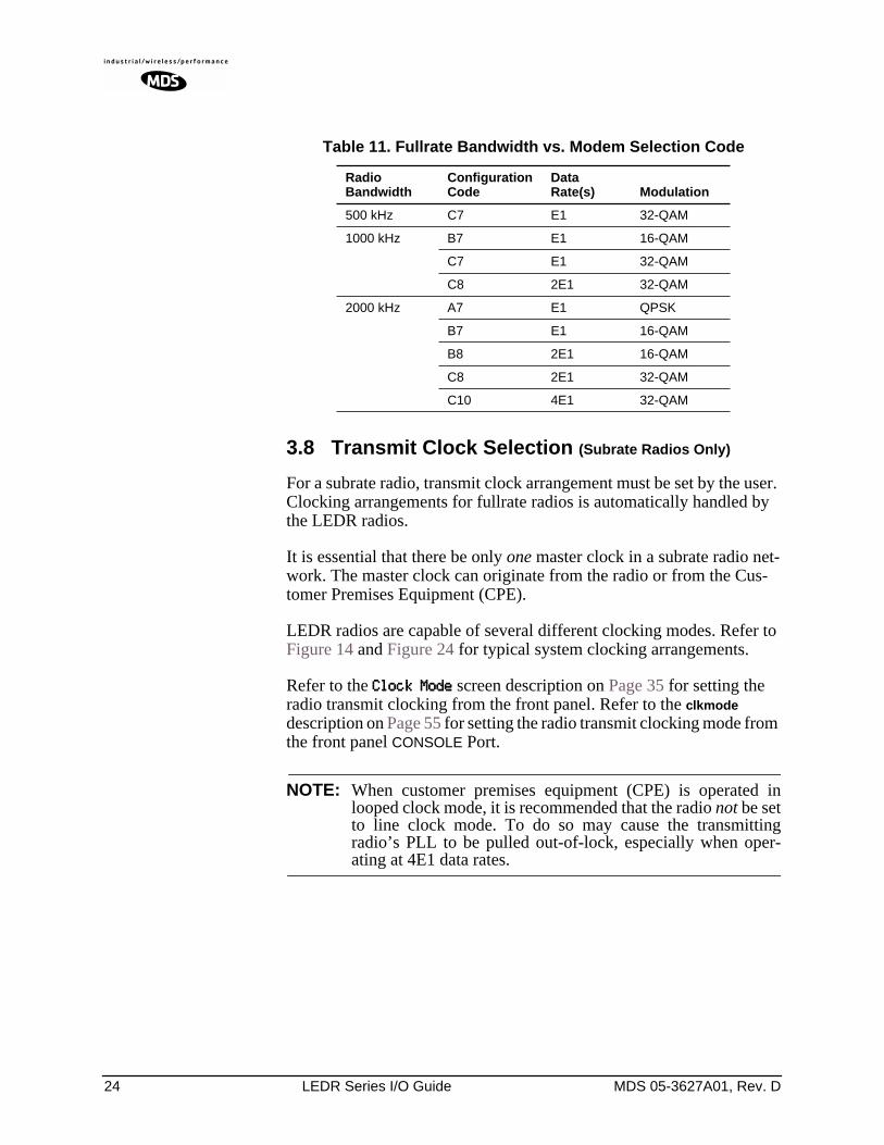
3.8 Transmit Clock Selection (Subrate Radios Only)
For a subrate radio, transmit clock arrangement must be set by the user. Clocking arrangements for fullrate radios is automatically handled by the LEDR radios.
It is essential that there be only one master clock in a subrate radio net-work. The master clock can originate from the radio or from the Cus-tomer Premises Equipment (CPE).
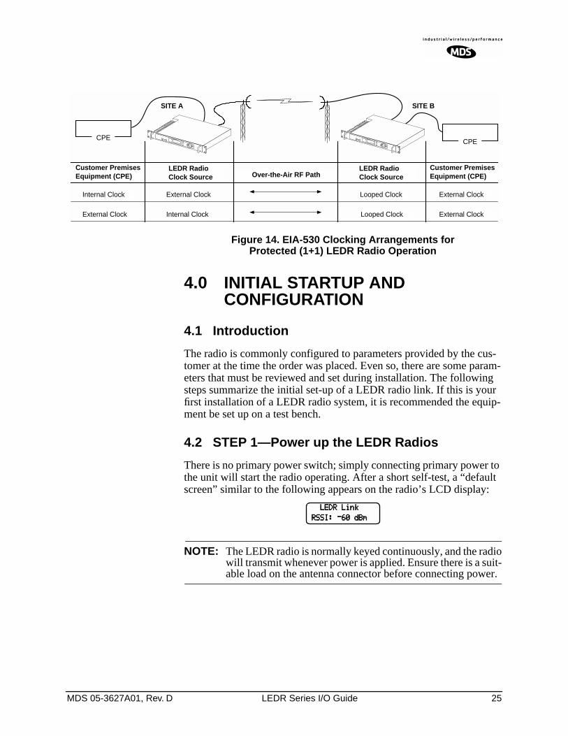
LEDR radios are capable of several different clocking modes. Refer to Figure 14 and Figure 24 for typical system clocking arrangements.
Refer to the CCCClllloooocccckkkk MMMMooooddddeeee screen description on Page 35 for setting the radio transmit clocking from the front panel. Refer to the clkmode description on Page 55 for setting the radio transmit clocking mode from the front panel CONSOLE Port.
NOTE: When customer premises equipment (CPE) is operated inlooped clock mode, it is recommended that the radio not be setto line clock mode. To do so may cause the transmittingradio’s PLL to be pulled out-of-lock, especially when oper-ating at 4E1 data rates.
Table 11. Fullrate Bandwidth vs. Modem Selection Code
Radio Bandwidth
Configuration Code
Data Rate(s) Modulation
500 kHz C7 E1 32-QAM
1000 kHz B7 E1 16-QAM
C7 E1 32-QAM
C8 2E1 32-QAM
2000 kHz A7 E1 QPSK
B7 E1 16-QAM
B8 2E1 16-QAM
C8 2E1 32-QAM
C10 4E1 32-QAM
MDS 05-3627A01, Rev. D LEDR Series I/O Guide 25
Figure 14. EIA-530 Clocking Arrangements for Protected (1+1) LEDR Radio Operation
4.0 INITIAL STARTUP AND CONFIGURATION
4.1 Introduction
The radio is commonly configured to parameters provided by the cus-tomer at the time the order was placed. Even so, there are some param-eters that must be reviewed and set during installation. The following steps summarize the initial set-up of a LEDR radio link. If this is your first installation of a LEDR radio system, it is recommended the equip-ment be set up on a test bench.
4.2 STEP 1—Power up the LEDR Radios
There is no primary power switch; simply connecting primary power to the unit will start the radio operating. After a short self-test, a “default screen” similar to the following appears on the radio’s LCD display:
NOTE: The LEDR radio is normally keyed continuously, and the radiowill transmit whenever power is applied. Ensure there is a suit-able load on the antenna connector before connecting power.
Over-the-Air RF Path
CPE
Customer PremisesEquipment (CPE)
LEDR RadioClock Source
CPE
Internal Clock External Clock Looped Clock External Clock
External Clock Internal Clock Looped Clock External Clock
Customer PremisesEquipment (CPE)
SITE A SITE B
LEDR RadioClock Source
LLLLEEEEDDDDRRRR LLLLiiiinnnnkkkk
RRRRSSSSSSSSIIII:::: ----66660000 ddddBBBBmmmm
26 LEDR Series I/O Guide MDS 05-3627A01, Rev. D
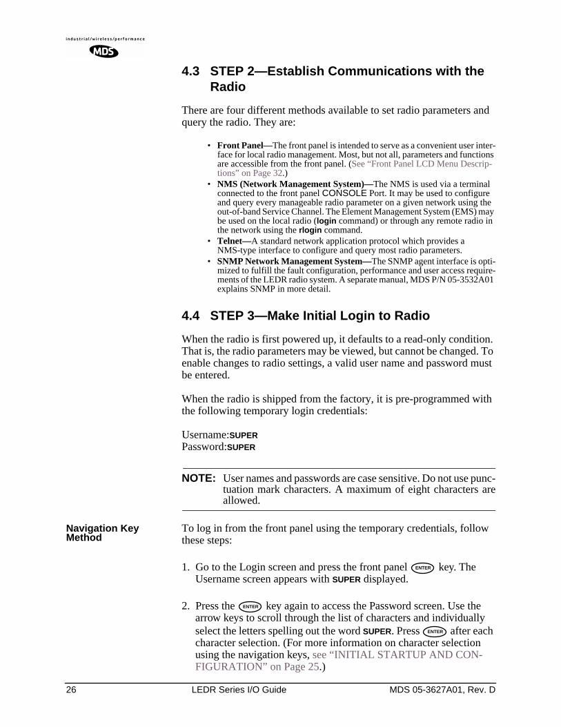
4.3 STEP 2—Establish Communications with the Radio
There are four different methods available to set radio parameters and query the radio. They are:
• Front Panel—The front panel is intended to serve as a convenient user inter-face for local radio management. Most, but not all, parameters and functions are accessible from the front panel. (See “Front Panel LCD Menu Descrip-tions” on Page 32.)
• NMS (Network Management System)—The NMS is used via a terminal connected to the front panel CONSOLE Port. It may be used to configure and query every manageable radio parameter on a given network using the out-of-band Service Channel. The Element Management System (EMS) may be used on the local radio (login command) or through any remote radio in the network using the rlogin command.
• Telnet—A standard network application protocol which provides a NMS-type interface to configure and query most radio parameters.
• SNMP Network Management System—The SNMP agent interface is opti-mized to fulfill the fault configuration, performance and user access require-ments of the LEDR radio system. A separate manual, MDS P/N 05-3532A01 explains SNMP in more detail.
4.4 STEP 3—Make Initial Login to Radio
When the radio is first powered up, it defaults to a read-only condition. That is, the radio parameters may be viewed, but cannot be changed. To enable changes to radio settings, a valid user name and password must be entered.
When the radio is shipped from the factory, it is pre-programmed with the following temporary login credentials:
Username:SUPERPassword:SUPER
NOTE: User names and passwords are case sensitive. Do not use punc-tuation mark characters. A maximum of eight characters areallowed.
Navigation Key Method
To log in from the front panel using the temporary credentials, follow these steps:
1. Go to the Login screen and press the front panel key. The Username screen appears with SUPER displayed.
2. Press the key again to access the Password screen. Use the arrow keys to scroll through the list of characters and individually select the letters spelling out the word SUPER. Press after each character selection. (For more information on character selection using the navigation keys, see “INITIAL STARTUP AND CON-FIGURATION” on Page 25.)
ENTER
ENTER
ENTER
MDS 05-3627A01, Rev. D LEDR Series I/O Guide 27
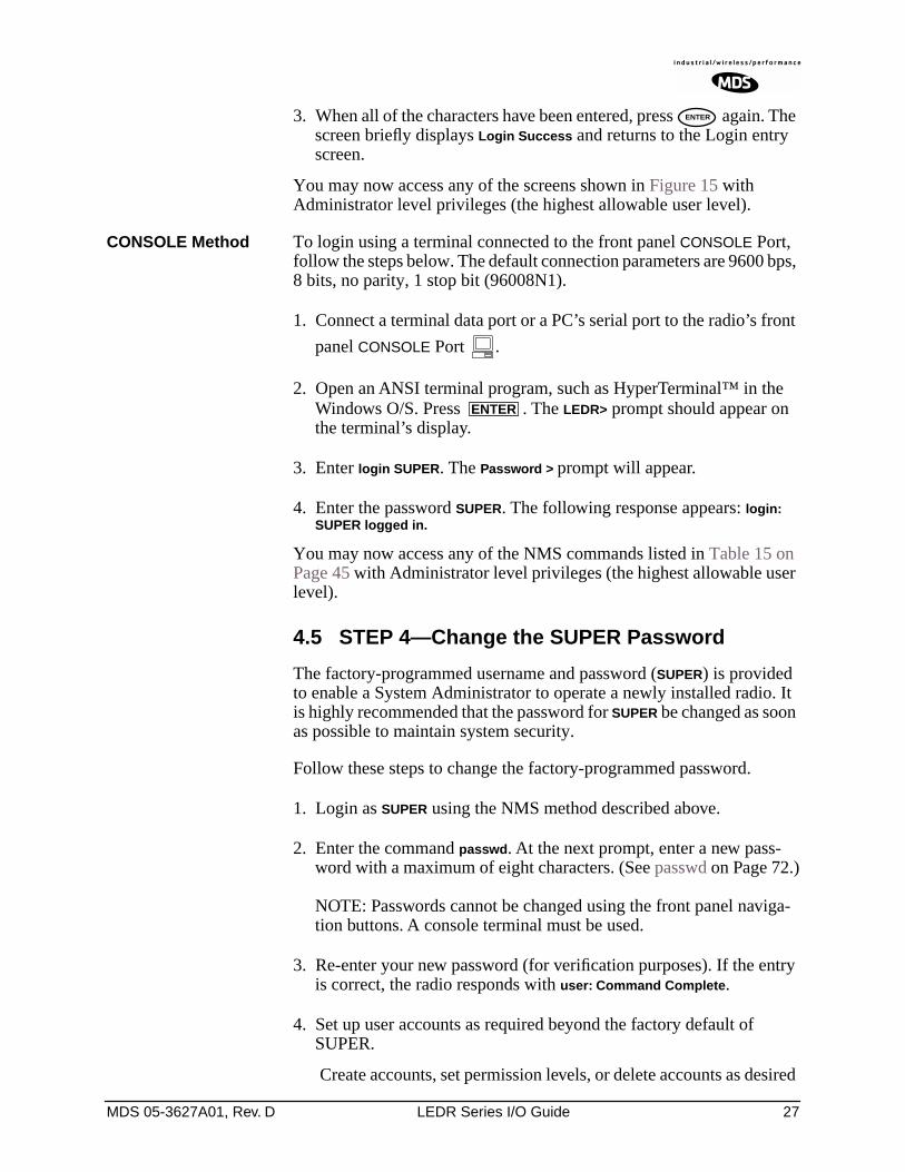
3. When all of the characters have been entered, press again. The screen briefly displays Login Success and returns to the Login entry screen.
You may now access any of the screens shown in Figure 15 with Administrator level privileges (the highest allowable user level).
CONSOLE Method To login using a terminal connected to the front panel CONSOLE Port, follow the steps below. The default connection parameters are 9600 bps, 8 bits, no parity, 1 stop bit (96008N1).
1. Connect a terminal data port or a PC’s serial port to the radio’s front
panel CONSOLE Port .
2. Open an ANSI terminal program, such as HyperTerminal™ in the Windows O/S. Press . The LEDR> prompt should appear on the terminal’s display.
3. Enter login SUPER. The Password > prompt will appear.
4. Enter the password SUPER. The following response appears: login: SUPER logged in.
You may now access any of the NMS commands listed in Table 15 on Page 45 with Administrator level privileges (the highest allowable user level).
4.5 STEP 4—Change the SUPER Password
The factory-programmed username and password (SUPER) is provided to enable a System Administrator to operate a newly installed radio. It is highly recommended that the password for SUPER be changed as soon as possible to maintain system security.
Follow these steps to change the factory-programmed password.
1. Login as SUPER using the NMS method described above.
2. Enter the command passwd. At the next prompt, enter a new pass-word with a maximum of eight characters. (See passwd on Page 72.)
NOTE: Passwords cannot be changed using the front panel naviga-tion buttons. A console terminal must be used.
3. Re-enter your new password (for verification purposes). If the entry is correct, the radio responds with user: Command Complete.
4. Set up user accounts as required beyond the factory default of SUPER.
Create accounts, set permission levels, or delete accounts as desired
ENTER
ENTER
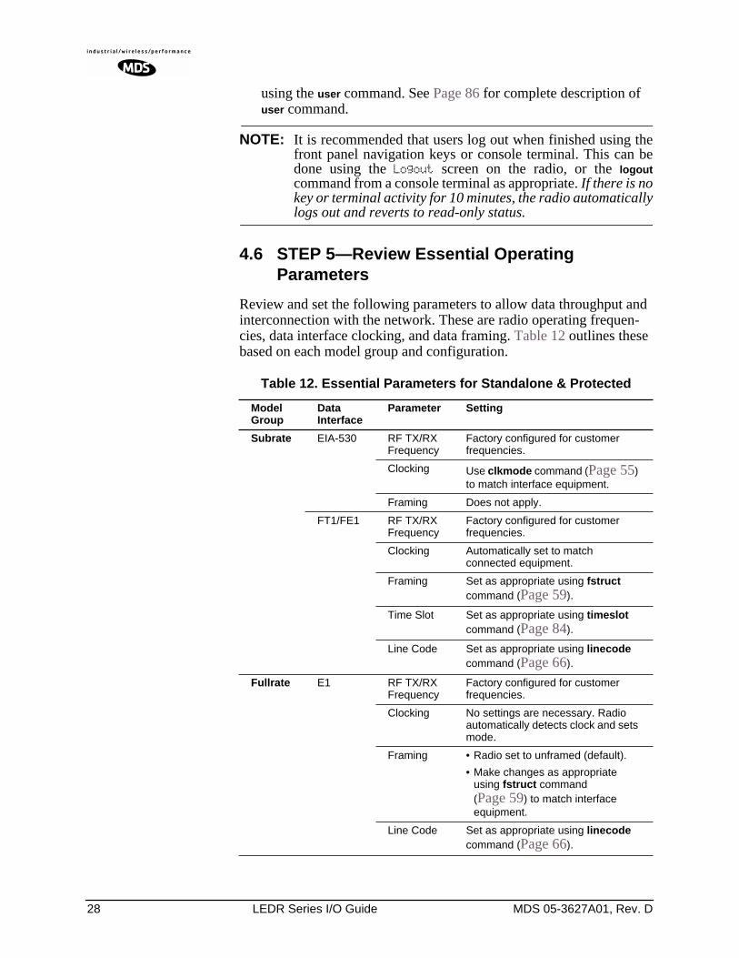
28 LEDR Series I/O Guide MDS 05-3627A01, Rev. D
using the user command. See Page 86 for complete description of user command.
NOTE: It is recommended that users log out when finished using thefront panel navigation keys or console terminal. This can bedone using the Logout screen on the radio, or the logoutcommand from a console terminal as appropriate. If there is nokey or terminal activity for 10 minutes, the radio automaticallylogs out and reverts to read-only status.
4.6 STEP 5—Review Essential Operating Parameters
Review and set the following parameters to allow data throughput and interconnection with the network. These are radio operating frequen-cies, data interface clocking, and data framing. Table 12 outlines these based on each model group and configuration.
Table 12. Essential Parameters for Standalone & Protected
ModelGroup
Data Interface
Parameter Setting
Subrate EIA-530 RF TX/RX Frequency
Factory configured for customer frequencies.
Clocking Use clkmode command (Page 55) to match interface equipment.
Framing Does not apply.
FT1/FE1 RF TX/RX Frequency
Factory configured for customer frequencies.
Clocking Automatically set to match connected equipment.
Framing Set as appropriate using fstruct command (Page 59).
Time Slot Set as appropriate using timeslot command (Page 84).
Line Code Set as appropriate using linecode command (Page 66).
Fullrate E1 RF TX/RX Frequency
Factory configured for customer frequencies.
Clocking No settings are necessary. Radio automatically detects clock and sets mode.
Framing • Radio set to unframed (default).
• Make changes as appropriate using fstruct command (Page 59) to match interface equipment.
Line Code Set as appropriate using linecode command (Page 66).
MDS 05-3627A01, Rev. D LEDR Series I/O Guide 29
4.7 STEP 6—Set TCP/IP Settings to Enable SNMP and/or Telnet Management (if required)• The unit IP address is factory configured with a unique address
based on the last three digits of the radio’s serial number.
• Use ip command (Page 63) to change the IP address, set net-mask, gateway and IP Port as necessary.
• In a protected radio, change the rdnt settings (Page 74) to match the user-assigned IP addresses.
4.8 STEP 7—Set User Configurable Fields
Change only if required.
Many items are user-configurable. These include, but are not lim-ited to the following. See the NMS command description in the manual for more detail:
• Set user information fields using info command (Page 62)
• Set alarms and alarm mappings using the alarm command (Page 50)
• Set event mappings using the evmap command (Page 58)
• Set alarm thresholds using the threshold command (Page 83)
• Set the SNMP community using the snmpcomm command (Page 81)
4.9 STEP 8—Verify Radio Performance
The data performance and NMS should be verified. Use the loop-back command (Page 69) to verify data throughput.
4.10 STEP 9—Install the Link
Peak the antennas for maximum RSSI using the continuously updated rssi command (Page 79), either the front panel screen or using the trend command (Page 85) via the NMS.
4.11 STEP 10—Verify the Link Performance
Connect and verify the proper operation of external equipment con-nected to the LEDR radio link.
5.0 CONFIGURATION AND CONTROL VIA THE FRONT PANEL
Figure 15 shown on the following pages is a pictorial view of the front panel menu tree. Detailed explanations of the screens are follow in Section 5.1, Front Panel LCD Menu Descriptions.
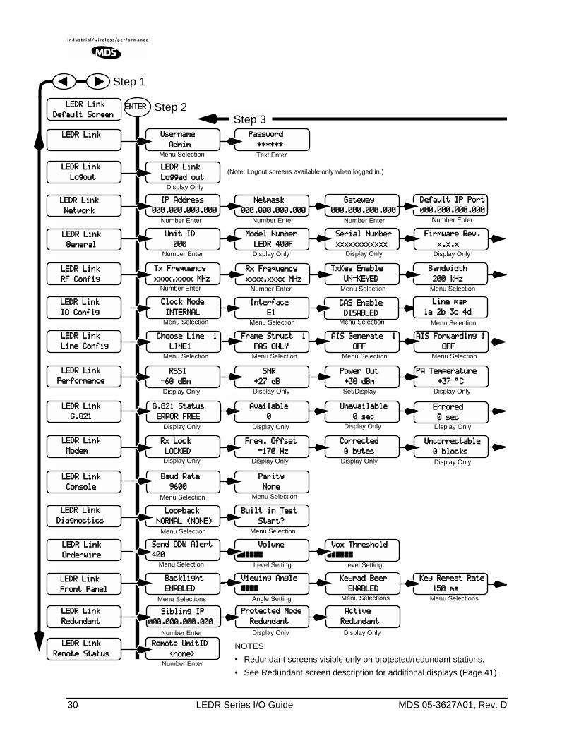
30 LEDR Series I/O Guide MDS 05-3627A01, Rev. D
UUUUsssseeeerrrrnnnnaaaammmmeeee
AAAAddddmmmmiiiinnnn PPPPaaaasssssssswwwwoooorrrrdddd
************************
IIIIPPPP AAAAddddddddrrrreeeessssssss
000000000000....000000000000....000000000000....000000000000 GGGGaaaatttteeeewwwwaaaayyyy
000000000000....000000000000....000000000000....000000000000 NNNNeeeettttmmmmaaaasssskkkk
000000000000....000000000000....000000000000....000000000000
FFFFiiiirrrrmmmmwwwwaaaarrrreeee RRRReeeevvvv....
xxxx....xxxx....xxxx SSSSeeeerrrriiiiaaaallll NNNNuuuummmmbbbbeeeerrrr
xxxxxxxxxxxxxxxxxxxxxxxxxxxxxxxxxxxxxxxxxxxxxxxx MMMMooooddddeeeellll NNNNuuuummmmbbbbeeeerrrr
LLLLEEEEDDDDRRRR 444400000000FFFF UUUUnnnniiiitttt IIIIDDDD
000000000000
BBBBaaaannnnddddwwwwiiiiddddtttthhhh
222200000000 kkkkHHHHzzzz TTTTxxxx FFFFrrrreeeeqqqquuuueeeennnnccccyyyy
xxxxxxxxxxxxxxxx....xxxxxxxxxxxxxxxx MMMMHHHHzzzz
PPPPAAAA TTTTeeeemmmmppppeeeerrrraaaattttuuuurrrreeee
++++33337777 °°°°CCCC PPPPoooowwwweeeerrrr OOOOuuuutttt
++++33330000 ddddBBBBmmmm SSSSNNNNRRRR
++++22227777 ddddBBBB RRRRSSSSSSSSIIII
----66660000 ddddBBBBmmmm
AAAAvvvvaaaaiiiillllaaaabbbblllleeee
0000 EEEErrrrrrrroooorrrreeeedddd
0000 sssseeeecccc
UUUUnnnnccccoooorrrrrrrreeeeccccttttaaaabbbblllleeee
0000 bbbblllloooocccckkkkssss CCCCoooorrrrrrrreeeecccctttteeeedddd
0000 bbbbyyyytttteeeessss
BBBBaaaauuuudddd RRRRaaaatttteeee
9999666600000000 PPPPaaaarrrriiiittttyyyy
NNNNoooonnnneeee
RRRRxxxx LLLLoooocccckkkk
LLLLOOOOCCCCKKKKEEEEDDDD
LLLLooooooooppppbbbbaaaacccckkkk
NNNNOOOORRRRMMMMAAAALLLL ((((NNNNOOOONNNNEEEE)))) BBBBuuuuiiiilllltttt iiiinnnn TTTTeeeesssstttt
SSSSttttaaaarrrrtttt????
SSSSeeeennnndddd OOOODDDDWWWW AAAAlllleeeerrrrtttt
444400000000
BBBBaaaacccckkkklllliiiigggghhhhtttt
EEEENNNNAAAABBBBLLLLEEEEDDDD VVVViiiieeeewwwwiiiinnnngggg AAAAnnnngggglllleeee
~~~~~~~~~~~~~~~~ KKKKeeeeyyyyppppaaaadddd BBBBeeeeeeeepppp
EEEENNNNAAAABBBBLLLLEEEEDDDD KKKKeeeeyyyy RRRReeeeppppeeeeaaaatttt RRRRaaaatttteeee
111155550000 mmmmssss
LLLLEEEEDDDDRRRR LLLLiiiinnnnkkkk
DDDDeeeeffffaaaauuuulllltttt SSSSccccrrrreeeeeeeennnn
LLLLEEEEDDDDRRRR LLLLiiiinnnnkkkk
LLLLEEEEDDDDRRRR LLLLiiiinnnnkkkk
NNNNeeeettttwwwwoooorrrrkkkk
LLLLEEEEDDDDRRRR LLLLiiiinnnnkkkk
GGGGeeeennnneeeerrrraaaallll
LLLLEEEEDDDDRRRR LLLLiiiinnnnkkkk
RRRRFFFF CCCCoooonnnnffffiiiigggg
LLLLEEEEDDDDRRRR LLLLiiiinnnnkkkk
PPPPeeeerrrrffffoooorrrrmmmmaaaannnncccceeee
LLLLEEEEDDDDRRRR LLLLiiiinnnnkkkk
GGGG....888822221111
LLLLEEEEDDDDRRRR LLLLiiiinnnnkkkk
CCCCoooonnnnssssoooolllleeee
LLLLEEEEDDDDRRRR LLLLiiiinnnnkkkk
MMMMooooddddeeeemmmm
LLLLEEEEDDDDRRRR LLLLiiiinnnnkkkk
DDDDiiiiaaaaggggnnnnoooossssttttiiiiccccssss
LLLLEEEEDDDDRRRR LLLLiiiinnnnkkkk
OOOOrrrrddddeeeerrrrwwwwiiiirrrreeee
LLLLEEEEDDDDRRRR LLLLiiiinnnnkkkk
FFFFrrrroooonnnntttt PPPPaaaannnneeeellll
EEEENNNNTTTTEEEERRRR Step 2Step 3
Display Only
Display Only
Display Only Display Only
Display Only
Display Only
Display Only
Menu Selections Menu SelectionsMenu Selections
Number Enter Number Enter Number Enter
Text EnterMenu Selection
Number Enter Number Enter
Display Only
Display OnlySet/Display
Number Enter
Display Only
Display Only
Display Only
Menu Selection
Menu Selection Menu Selection
Menu Selection
Menu Selection
Menu SelectionMenu Selection
Step 1
RRRRxxxx FFFFrrrreeeeqqqquuuueeeennnnccccyyyy
xxxxxxxxxxxxxxxx....xxxxxxxxxxxxxxxx MMMMHHHHzzzz TTTTxxxxKKKKeeeeyyyy EEEEnnnnaaaabbbblllleeee
UUUUNNNN----KKKKEEEEYYYYEEEEDDDD
Display Only Display Only
VVVVoooolllluuuummmmeeee
~~~~~~~~~~~~~~~~~~~~~~~~ VVVVooooxxxx TTTThhhhrrrreeeesssshhhhoooolllldddd
~~~~~~~~~~~~~~~~~~~~~~~~Level Setting Level Setting
Angle Setting
GGGG....888822221111 SSSSttttaaaattttuuuussss
EEEERRRRRRRROOOORRRR FFFFRRRREEEEEEEE UUUUnnnnaaaavvvvaaaaiiiillllaaaabbbblllleeee
0000 sssseeeecccc
FFFFrrrreeeeqqqq.... OOOOffffffffsssseeeetttt
----111177770000 HHHHzzzz
DDDDeeeeffffaaaauuuulllltttt IIIIPPPP PPPPoooorrrrtttt
000000000000....000000000000....000000000000....000000000000Number Enter
LLLLEEEEDDDDRRRR LLLLiiiinnnnkkkk
LLLLooooggggoooouuuutttt LLLLEEEEDDDDRRRR LLLLiiiinnnnkkkk
LLLLooooggggggggeeeedddd oooouuuutttt
Number Enter
Display Only
(Note: Logout screens available only when logged in.)
SSSSiiiibbbblllliiiinnnngggg IIIIPPPP
000000000000....000000000000....000000000000....000000000000 PPPPrrrrooootttteeeecccctttteeeedddd MMMMooooddddeeee
RRRReeeedddduuuunnnnddddaaaannnntttt AAAAccccttttiiiivvvveeee
RRRReeeedddduuuunnnnddddaaaannnntttt
LLLLEEEEDDDDRRRR LLLLiiiinnnnkkkk
RRRReeeedddduuuunnnnddddaaaannnntttt
Display Only Display OnlyNumber Enter
RRRReeeemmmmooootttteeee UUUUnnnniiiittttIIIIDDDD
<<<<nnnnoooonnnneeee>>>>Number Enter
LLLLEEEEDDDDRRRR LLLLiiiinnnnkkkk
IIIIOOOO CCCCoooonnnnffffiiiigggg
LLLLEEEEDDDDRRRR LLLLiiiinnnnkkkk
LLLLiiiinnnneeee CCCCoooonnnnffffiiiigggg
LLLLEEEEDDDDRRRR LLLLiiiinnnnkkkk
RRRReeeemmmmooootttteeee SSSSttttaaaattttuuuussss
CCCClllloooocccckkkk MMMMooooddddeeee
IIIINNNNTTTTEEEERRRRNNNNAAAALLLLMenu Selection
IIIInnnntttteeeerrrrffffaaaacccceeee
EEEE1111Menu Selection Menu Selection
CCCCAAAASSSS EEEEnnnnaaaabbbblllleeee
DDDDIIIISSSSAAAABBBBLLLLEEEEDDDDMenu Selection
CCCChhhhoooooooosssseeee LLLLiiiinnnneeee 1111
LLLLIIIINNNNEEEE1111Menu Selection
FFFFrrrraaaammmmeeee SSSSttttrrrruuuucccctttt 1111
FFFFAAAASSSS OOOONNNNLLLLYYYYMenu Selection
AAAAIIIISSSS GGGGeeeennnneeeerrrraaaatttteeee 1111
OOOOFFFFFFFFAAAAIIIISSSS FFFFoooorrrrwwwwaaaarrrrddddiiiinnnngggg 1111
OOOOFFFFFFFFMenu SelectionMenu Selection
NOTES:
• Redundant screens visible only on protected/redundant stations.
• See Redundant screen description for additional displays (Page 41).
LLLLiiiinnnneeee mmmmaaaapppp
1111aaaa 2222bbbb 3333cccc 4444dddd
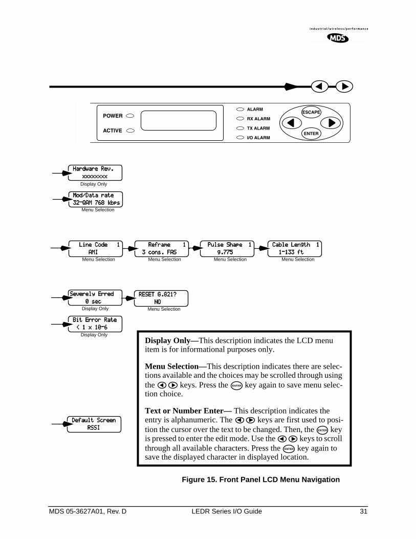
MDS 05-3627A01, Rev. D LEDR Series I/O Guide 31
HHHHaaaarrrrddddwwwwaaaarrrreeee RRRReeeevvvv....
xxxxxxxxxxxxxxxxxxxxxxxxxxxxxxxx
SSSSeeeevvvveeeerrrreeeellllyyyy EEEErrrrrrrreeeedddd
0000 sssseeeecccc
DDDDeeeeffffaaaauuuulllltttt SSSSccccrrrreeeeeeeennnn
RRRRSSSSSSSSIIII
Display Only
Menu Selection
Display Only
Display OnlyDisplay Only—This description indicates the LCD menu item is for informational purposes only.
Menu Selection—This description indicates there are selec-tions available and the choices may be scrolled through using the keys. Press the key again to save menu selec-tion choice.
Text or Number Enter— This description indicates the entry is alphanumeric. The keys are first used to posi-tion the cursor over the text to be changed. Then, the key is pressed to enter the edit mode. Use the keys to scroll through all available characters. Press the key again to save the displayed character in displayed location.
ENTER
ENTER
ENTER
RRRREEEESSSSEEEETTTT GGGG....888822221111????
NNNNOOOO Menu Selection
MMMMoooodddd////DDDDaaaattttaaaa rrrraaaatttteeee
33332222----QQQQAAAAMMMM 777766668888 kkkkbbbbppppssss
BBBBiiiitttt EEEErrrrrrrroooorrrr RRRRaaaatttteeee
<<<< 1111 xxxx 11110000----6666
LLLLiiiinnnneeee CCCCooooddddeeee 1111
AAAAMMMMIIIIMenu Selection
RRRReeeeffffrrrraaaammmmeeee 1111
3333 ccccoooonnnnssss.... FFFFAAAASSSSMenu Selection
PPPPuuuullllsssseeee SSSShhhhaaaappppeeee 1111
gggg....777777775555Menu Selection
CCCCaaaabbbblllleeee LLLLeeeennnnggggtttthhhh 1111
1111----111133333333 ffffttttMenu Selection
Figure 15. Front Panel LCD Menu Navigation
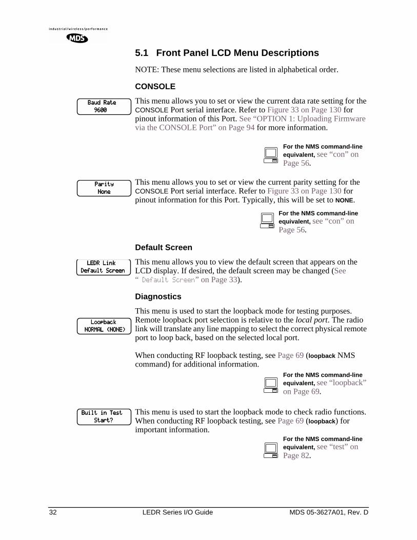
32 LEDR Series I/O Guide MDS 05-3627A01, Rev. D
5.1 Front Panel LCD Menu Descriptions
NOTE: These menu selections are listed in alphabetical order.
CONSOLE
This menu allows you to set or view the current data rate setting for the CONSOLE Port serial interface. Refer to Figure 33 on Page 130 for pinout information of this Port. See “OPTION 1: Uploading Firmware via the CONSOLE Port” on Page 94 for more information.
This menu allows you to set or view the current parity setting for the CONSOLE Port serial interface. Refer to Figure 33 on Page 130 for pinout information for this Port. Typically, this will be set to NONE.
Default Screen
This menu allows you to view the default screen that appears on the LCD display. If desired, the default screen may be changed (See “ Default Screen” on Page 33).
Diagnostics
This menu is used to start the loopback mode for testing purposes. Remote loopback port selection is relative to the local port. The radio link will translate any line mapping to select the correct physical remote port to loop back, based on the selected local port.
When conducting RF loopback testing, see Page 69 (loopback NMS command) for additional information.
This menu is used to start the loopback mode to check radio functions. When conducting RF loopback testing, see Page 69 (loopback) for important information.
BBBBaaaauuuudddd RRRRaaaatttteeee
9999666600000000
For the NMS command-line equivalent, see “con” on Page 56.
PPPPaaaarrrriiiittttyyyy
NNNNoooonnnneeee
For the NMS command-line equivalent, see “con” on Page 56.
LLLLEEEEDDDDRRRR LLLLiiiinnnnkkkk
DDDDeeeeffffaaaauuuulllltttt SSSSccccrrrreeeeeeeennnn
LLLLooooooooppppbbbbaaaacccckkkk
NNNNOOOORRRRMMMMAAAALLLL ((((NNNNOOOONNNNEEEE))))
For the NMS command-line equivalent, see “loopback” on Page 69.
BBBBuuuuiiiilllltttt iiiinnnn TTTTeeeesssstttt
SSSSttttaaaarrrrtttt????
For the NMS command-line equivalent, see “test” on Page 82.
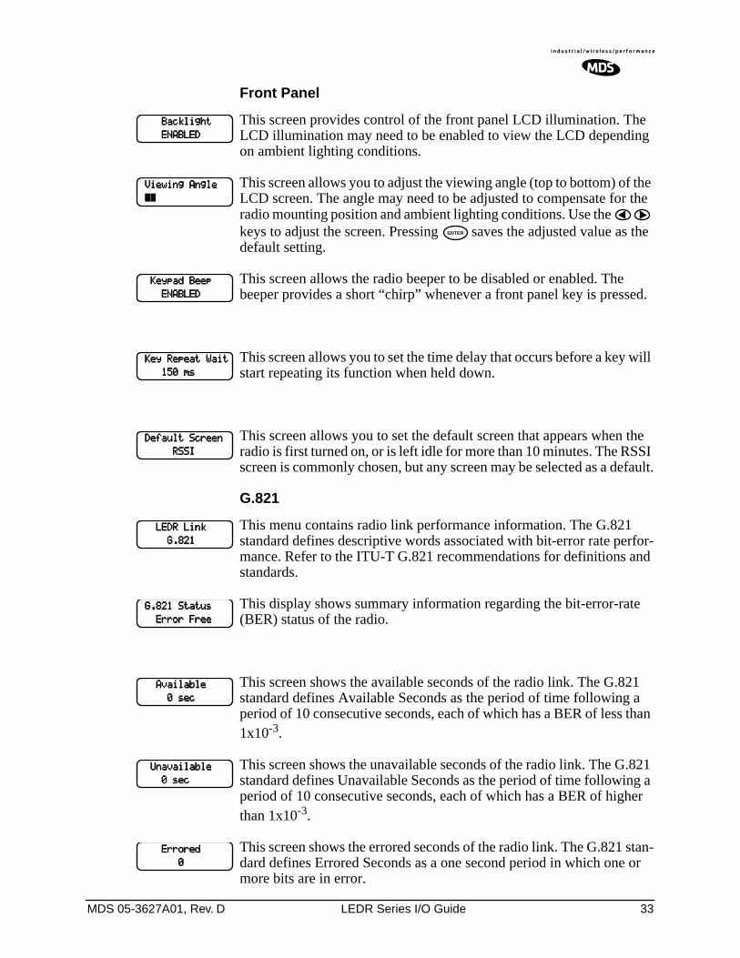
MDS 05-3627A01, Rev. D LEDR Series I/O Guide 33
Front Panel
This screen provides control of the front panel LCD illumination. The LCD illumination may need to be enabled to view the LCD depending on ambient lighting conditions.
This screen allows you to adjust the viewing angle (top to bottom) of the LCD screen. The angle may need to be adjusted to compensate for the radio mounting position and ambient lighting conditions. Use the keys to adjust the screen. Pressing saves the adjusted value as the default setting.
This screen allows the radio beeper to be disabled or enabled. The beeper provides a short “chirp” whenever a front panel key is pressed.
This screen allows you to set the time delay that occurs before a key will start repeating its function when held down.
This screen allows you to set the default screen that appears when the radio is first turned on, or is left idle for more than 10 minutes. The RSSI screen is commonly chosen, but any screen may be selected as a default.
G.821
This menu contains radio link performance information. The G.821 standard defines descriptive words associated with bit-error rate perfor-mance. Refer to the ITU-T G.821 recommendations for definitions and standards.
This display shows summary information regarding the bit-error-rate (BER) status of the radio.
This screen shows the available seconds of the radio link. The G.821 standard defines Available Seconds as the period of time following a period of 10 consecutive seconds, each of which has a BER of less than 1x10⁻³.
This screen shows the unavailable seconds of the radio link. The G.821 standard defines Unavailable Seconds as the period of time following a period of 10 consecutive seconds, each of which has a BER of higher than 1x10⁻³.
This screen shows the errored seconds of the radio link. The G.821 stan-dard defines Errored Seconds as a one second period in which one or more bits are in error.
BBBBaaaacccckkkklllliiiigggghhhhtttt
EEEENNNNAAAABBBBLLLLEEEEDDDD
VVVViiiieeeewwwwiiiinnnngggg AAAAnnnngggglllleeee
~~~~~~~~
ENTER
KKKKeeeeyyyyppppaaaadddd BBBBeeeeeeeepppp
EEEENNNNAAAABBBBLLLLEEEEDDDD
KKKKeeeeyyyy RRRReeeeppppeeeeaaaatttt WWWWaaaaiiiitttt
111155550000 mmmmssss
DDDDeeeeffffaaaauuuulllltttt SSSSccccrrrreeeeeeeennnn
RRRRSSSSSSSSIIII
LLLLEEEEDDDDRRRR LLLLiiiinnnnkkkk
GGGG....888822221111
GGGG....888822221111 SSSSttttaaaattttuuuussss
EEEErrrrrrrroooorrrr FFFFrrrreeeeeeee
AAAAvvvvaaaaiiiillllaaaabbbblllleeee
0000 sssseeeecccc
UUUUnnnnaaaavvvvaaaaiiiillllaaaabbbblllleeee
0000 sssseeeecccc
EEEErrrrrrrroooorrrreeeedddd
0000
34 LEDR Series I/O Guide MDS 05-3627A01, Rev. D
This screen shows the severely errored seconds of the radio link. The G.821 standard defines Severely Errored Seconds as a one second period that has a BER higher than 1x10⁻³.
This screen allows the user to reset the G.821 performance monitoring screens.
General
This menu allows the Unit ID of the radio to be displayed or changed. The Unit ID allows an individual radio to be signaled for Orderwire use.
This menu displays the radio model number. The user cannot change the radio type.
This menu displays the radio serial number and matches the serial number on the chassis sticker. The user cannot change the radio’s serial number.
This menu displays the firmware revision level of the internal radio soft-ware.
This menu displays the hardware revision level of the main PC board in the radio.
SSSSeeeevvvveeeerrrreeeellllyyyy EEEErrrrrrrreeeedddd
0000
RRRReeeesssseeeetttt GGGG....888822221111????
NNNNOOOO
UUUUnnnniiiitttt IIIIDDDD
000000000000
For the NMS command-line equivalent, see “unitid” on Page 86.
MMMMooooddddeeeellll NNNNuuuummmmbbbbeeeerrrr
LLLLEEEEDDDDRRRR 1111444400000000SSSS
For the NMS command-line equivalent, see “model” on Page 71.
SSSSeeeerrrriiiiaaaallll NNNNuuuummmmbbbbeeeerrrr
xxxxxxxxxxxxxxxxxxxxxxxxxxxxxxxxxxxxxxxxxxxxxxxx
For the NMS command-line equivalent, see “sernum” on Page 81.
FFFFiiiirrrrmmmmwwwwaaaarrrreeee RRRReeeevvvv....
xxxxxxxxxxxxxxxxxxxxxxxxxxxxxxxx
For the NMS command-line equivalent, see “ver” on Page 87.
HHHHaaaarrrrddddwwwwaaaarrrreeee RRRReeeevvvv....
xxxxxxxxxxxxxxxxxxxxxxxxxxxxxxxx
For the NMS command-line equivalent, see “ver” on Page 87.
MDS 05-3627A01, Rev. D LEDR Series I/O Guide 35
IO Configuration
This screen is used to set or display the data clocking method. For syn-chronization purposes, several different clocking schemes can be used. See Table 10 on Page 23 for the combinations of radio bandwidth, data rates and modulation types available for subrate radios. Table 11 on Page 24 contains the same information for fullrate radios.
NOTE: For subrate models: LEDR 400S/900S/1400SEarlier versions of the software may display the Clock Modeas NORMAL instead of INTERNAL.
This screen is used to set or display the payload data interface. The available selections are E1, T1 and EIA530, depending on hardware configuration of the LEDR radio.
This screen is used to set or display the Channel Associated Signaling (CAS) status. The available selections are Enabled and Disabled.
This screen will only be functional in radios factory-equipped to support CAS. Consult the factory if you require this service.
This screen is used to set or display the current span mapping configu-ration. The entry consists of from 1 to 4 alpha-numeric characters spec-ifying line interface to span mapping. Valid numbers are 1–4. Valid span characters are a–d.
Example: Entering 1a 2b 3c 4d asserts the following:
maps line 1 to span amaps line 2 to span bmaps line 3 to span cmaps line 4 to span d
CCCClllloooocccckkkk MMMMooooddddeeee
IIIINNNNTTTTEEEERRRRNNNNAAAALLLL
For the NMS command-line equivalent, see “date” on Page 57.
IIIInnnntttteeeerrrrffffaaaacccceeee
EEEE1111
For the NMS command-line equivalent, see “interface” on Page 62.
CCCCAAAASSSS EEEEnnnnaaaabbbblllleeee
DDDDIIIISSSSAAAABBBBLLLLEEEEDDDD
For the NMS command-line equivalent, see “modem” on Page 71.
LLLLiiiinnnneeee mmmmaaaapppp
1111aaaa 2222bbbb 3333cccc 4444dddd
For the NMS command-line equivalent, see “linemap” on Page 66.
36 LEDR Series I/O Guide MDS 05-3627A01, Rev. D
Line Configuration
This screen is used to choose or display the line (1-4) that is selected. This selection will be active for all of the screens that follow in the Line Configuration menu and will be displayed in the upper right hand corner of each screen.
This screen is used to set or display the span(s) frame structure. The allowable selections are shown in Table 13.
This screen is used to set or display the Alarm Indication Signal (AIS) status. It may be set to ON or OFF. When generation is enabled, fault conditions within the link or at the line interface will cause the appro-priate AIS signaling to occur.
This screen is used to set or display the Alarm Indication Signal (AIS) forwarding status. It may be set to ON or OFF. When forwarding is enabled, AIS/RAI signaling at the line interfaces will be detected and passed to the other end of the radio link.
CCCChhhhoooooooosssseeee LLLLiiiinnnneeee 1111
LLLLIIIINNNNEEEE1111
For the NMS command-line equivalent, see “linename” on Page 67.
FFFFrrrraaaammmmeeee SSSSttttrrrruuuucccctttt 1111
FFFFAAAASSSS OOOONNNNLLLLYYYY
Table 13. Frame Structure—Allowable Selections
T1 Operation E1 Operation
0–FT only (Default) 0–FAS Only (Default)
1–ESF 1–FAS + BSLIP
2–ESF + PRM 2–FAS + CRC
3–SF 3–FAS + CRC + BSLIP
4–SF + JYEL 4–FAS + CAS
5–ESF + CRC 5–FAS + CAS + BSLIP
6–ESF + CRC + PRM 6–FAS + CRC + CAS
7–Unframed (none) 7–FAS +CRC + CAS +BSLIP
8–Unframed (none)
For the NMS command-line equivalent, see “fstruct” on Page 59.
AAAAIIIISSSS GGGGeeeennnneeeerrrraaaatttteeee 1111
OOOOFFFFFFFF
For the NMS command-line equivalent, see “ais” on Page 49.
AAAAIIIISSSS FFFFoooorrrrwwwwaaaarrrrddddiiiinnnngggg 1111
OOOOFFFFFFFF
For the NMS command-line equivalent, see “ais” on Page 49.
MDS 05-3627A01, Rev. D LEDR Series I/O Guide 37
This screen is used to set or display the linecode used by the radio. The available selections are AMI or HDB3.
This screen is used to set or display the reframe criteria of the LEDR radio. The setting is based on the number of errors encountered. The available selections for T1 and E1 operation are listed in Table 14 below.
This command is used to select or display the pulse shape used with the data interface cable. The chart below shows the available selections for T1 and E1 operation.
This command is used to set or display the cable length being used for the data interface. The available selections are:
1 to 133 feet (Default)133 to 266 feet266 to 399 feet399 to 533 feet533 to 655 feet
LLLLiiiinnnneeee CCCCooooddddeeee 1111
AAAAMMMMIIII
For the NMS command-line equivalent, see “linecode” on Page 66.
RRRReeeeffffrrrraaaammmmeeee 1111
3333 ccccoooonnnnssss.... FFFFAAAASSSS
Table 14. Reframe Criteria Selections
T1 Operation E1 Operation
2 out of 4 Fbit errors (Default) 3 consecutive FAS errors (Default)
2 out of 5 Fbit errors 915 CRC errors
2 out of 6 Fbit errors
Specification
g.775 (Default)
i.431
For the NMS command-line equivalent, see “reframe” on Page 75.
PPPPuuuullllsssseeee SSSShhhhaaaappppeeee 1111
gggg....777777775555
For the NMS command-line equivalent, see “line” on Page 65.
CCCCaaaabbbblllleeee LLLLeeeennnnggggtttthhhh 1111
1111----111133333333 fffftttt
For the NMS command-line equivalent, see “line” on Page 65.
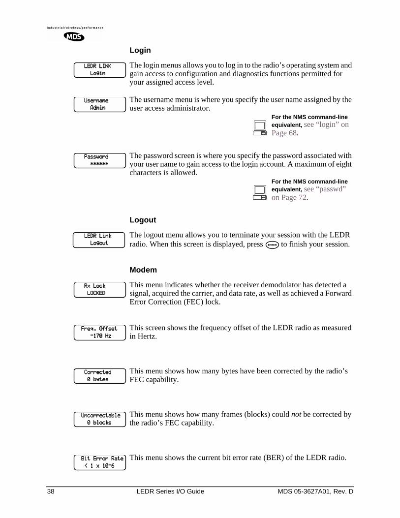
38 LEDR Series I/O Guide MDS 05-3627A01, Rev. D
Login
The login menus allows you to log in to the radio’s operating system and gain access to configuration and diagnostics functions permitted for your assigned access level.
The username menu is where you specify the user name assigned by the user access administrator.
The password screen is where you specify the password associated with your user name to gain access to the login account. A maximum of eight characters is allowed.
Logout
The logout menu allows you to terminate your session with the LEDR radio. When this screen is displayed, press to finish your session.
Modem
This menu indicates whether the receiver demodulator has detected a signal, acquired the carrier, and data rate, as well as achieved a Forward Error Correction (FEC) lock.
This screen shows the frequency offset of the LEDR radio as measured in Hertz.
This menu shows how many bytes have been corrected by the radio’s FEC capability.
This menu shows how many frames (blocks) could not be corrected by the radio’s FEC capability.
This menu shows the current bit error rate (BER) of the LEDR radio.
LLLLEEEEDDDDRRRR LLLLIIIINNNNKKKK
LLLLooooggggiiiinnnn
UUUUsssseeeerrrrnnnnaaaammmmeeee
AAAAddddmmmmiiiinnnn
For the NMS command-line equivalent, see “login” on Page 68.
PPPPaaaasssssssswwwwoooorrrrdddd
************************
For the NMS command-line equivalent, see “passwd” on Page 72.
LLLLEEEEDDDDRRRR LLLLiiiinnnnkkkk
LLLLooooggggoooouuuutttt ENTER
RRRRxxxx LLLLoooocccckkkk
LLLLOOOOCCCCKKKKEEEEDDDD
FFFFrrrreeeeqqqq.... OOOOffffffffsssseeeetttt
----111177770000 HHHHzzzz
CCCCoooorrrrrrrreeeecccctttteeeedddd
0000 bbbbyyyytttteeeessss
UUUUnnnnccccoooorrrrrrrreeeeccccttttaaaabbbblllleeee
0000 bbbblllloooocccckkkkssss
BBBBiiiitttt EEEErrrrrrrroooorrrr RRRRaaaatttteeee
<<<< 1111 xxxx 11110000----6666
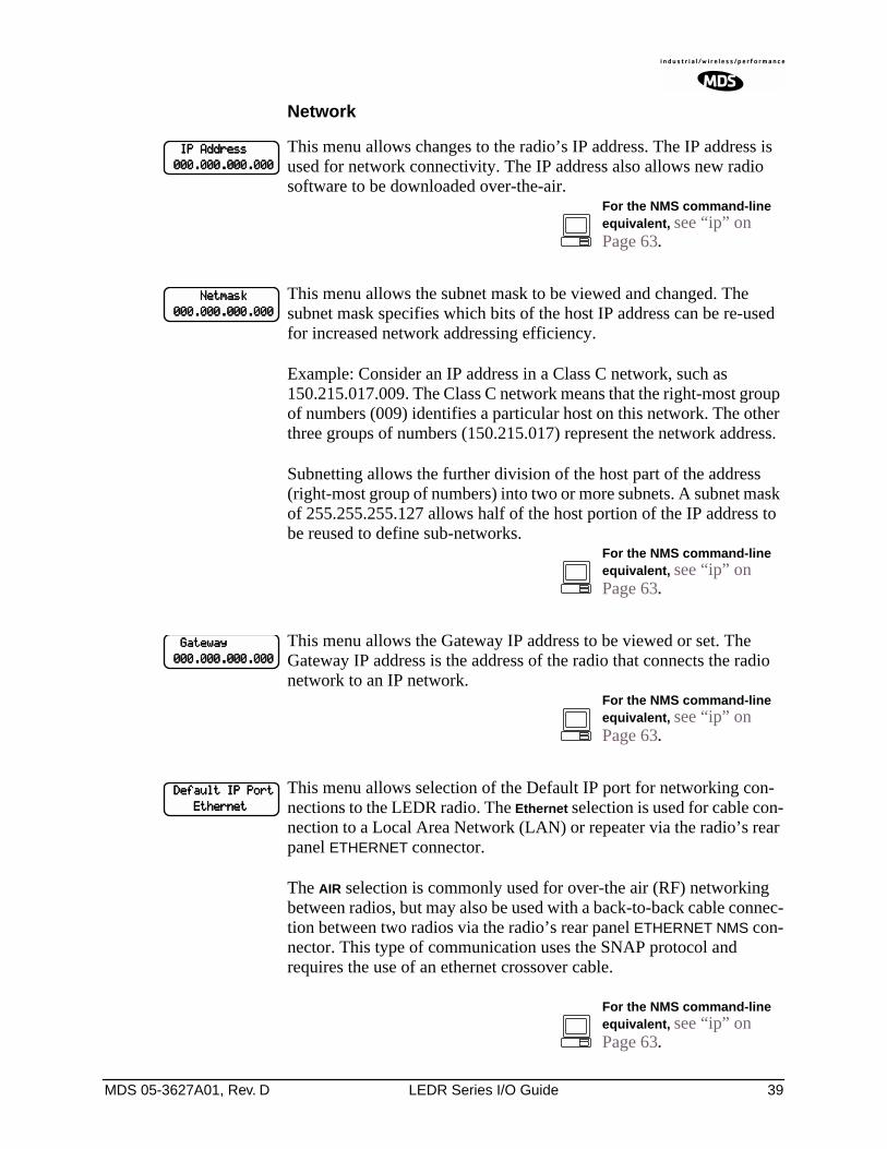
MDS 05-3627A01, Rev. D LEDR Series I/O Guide 39
Network
This menu allows changes to the radio’s IP address. The IP address is used for network connectivity. The IP address also allows new radio software to be downloaded over-the-air.
This menu allows the subnet mask to be viewed and changed. The subnet mask specifies which bits of the host IP address can be re-used for increased network addressing efficiency.
Example: Consider an IP address in a Class C network, such as 150.215.017.009. The Class C network means that the right-most group of numbers (009) identifies a particular host on this network. The other three groups of numbers (150.215.017) represent the network address.
Subnetting allows the further division of the host part of the address (right-most group of numbers) into two or more subnets. A subnet mask of 255.255.255.127 allows half of the host portion of the IP address to be reused to define sub-networks.
This menu allows the Gateway IP address to be viewed or set. The Gateway IP address is the address of the radio that connects the radio network to an IP network.
This menu allows selection of the Default IP port for networking con-nections to the LEDR radio. The Ethernet selection is used for cable con-nection to a Local Area Network (LAN) or repeater via the radio’s rear panel ETHERNET connector.
The AIR selection is commonly used for over-the air (RF) networking between radios, but may also be used with a back-to-back cable connec-tion between two radios via the radio’s rear panel ETHERNET NMS con-nector. This type of communication uses the SNAP protocol and requires the use of an ethernet crossover cable.
IIIIPPPP AAAAddddddddrrrreeeessssssss
000000000000....000000000000....000000000000....000000000000
For the NMS command-line equivalent, see “ip” on Page 63.
NNNNeeeettttmmmmaaaasssskkkk
000000000000....000000000000....000000000000....000000000000
For the NMS command-line equivalent, see “ip” on Page 63.
GGGGaaaatttteeeewwwwaaaayyyy
000000000000....000000000000....000000000000....000000000000
For the NMS command-line equivalent, see “ip” on Page 63.
DDDDeeeeffffaaaauuuulllltttt IIIIPPPP PPPPoooorrrrtttt
EEEEtttthhhheeeerrrrnnnneeeetttt
For the NMS command-line equivalent, see “ip” on Page 63.
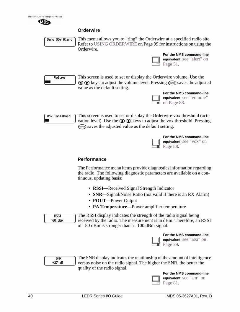
40 LEDR Series I/O Guide MDS 05-3627A01, Rev. D
Orderwire
This menu allows you to “ring” the Orderwire at a specified radio site. Refer to USING ORDERWIRE on Page 99 for instructions on using the Orderwire.
This screen is used to set or display the Orderwire volume. Use the keys to adjust the volume level. Pressing saves the adjusted
value as the default setting.
This screen is used to set or display the Orderwire vox threshold (acti-vation level). Use the keys to adjust the vox threshold. Pressing
saves the adjusted value as the default setting.
Performance
The Performance menu items provide diagnostics information regarding the radio. The following diagnostic parameters are available on a con-tinuous, updating basis:
• RSSI—Received Signal Strength Indicator• SNR—Signal/Noise Ratio (not valid if there is an RX Alarm)• POUT—Power Output• PA Temperature—Power amplifier temperature
The RSSI display indicates the strength of the radio signal being received by the radio. The measurement is in dBm. Therefore, an RSSI of –80 dBm is stronger than a –100 dBm signal.
The SNR display indicates the relationship of the amount of intelligence versus noise on the radio signal. The higher the SNR, the better the quality of the radio signal.
SSSSeeeennnndddd OOOODDDDWWWW AAAAlllleeeerrrrtttt
For the NMS command-line equivalent, see “alert” on Page 51.
VVVVoooolllluuuummmmeeee
~~~~~~~~~~~~ ENTER
For the NMS command-line equivalent, see “volume” on Page 88.
VVVVooooxxxx TTTThhhhrrrreeeesssshhhhoooolllldddd
~~~~~~~~
ENTER
For the NMS command-line equivalent, see “vox” on Page 88.
RRRRSSSSSSSSIIII
----66660000 ddddBBBBmmmm
For the NMS command-line equivalent, see “rssi” on Page 79.
SSSSNNNNRRRR
++++22227777 ddddBBBB
For the NMS command-line equivalent, see “snr” on Page 81.
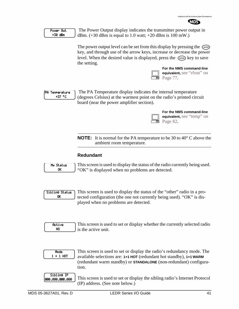
MDS 05-3627A01, Rev. D LEDR Series I/O Guide 41
The Power Output display indicates the transmitter power output in dBm. (+30 dBm is equal to 1.0 watt; +20 dBm is 100 mW.)
The power output level can be set from this display by pressing the key, and through use of the arrow keys, increase or decrease the power level. When the desired value is displayed, press the key to save the setting.
The PA Temperature display indicates the internal temperature (degrees Celsius) at the warmest point on the radio’s printed circuit board (near the power amplifier section).
NOTE: It is normal for the PA temperature to be 30 to 40° C above theambient room temperature.
Redundant
This screen is used to display the status of the radio currently being used. “OK” is displayed when no problems are detected.
This screen is used to display the status of the “other” radio in a pro-tected configuration (the one not currently being used). “OK” is dis-played when no problems are detected.
This screen is used to set or display whether the currently selected radio is the active unit.
This screen is used to set or display the radio’s redundancy mode. The available selections are: 1+1 HOT (redundant hot standby), 1+1 WARM (redundant warm standby) or STANDALONE (non-redundant) configura-tion.
This screen is used to set or display the sibling radio’s Internet Protocol (IP) address. (See note below.)
PPPPoooowwwweeeerrrr OOOOuuuutttt
++++33330000 ddddBBBBmmmm
ENTER
ENTER
For the NMS command-line equivalent, see “rfout” on Page 77.
PPPPAAAA TTTTeeeemmmmppppeeeerrrraaaattttuuuurrrreeee
++++33337777 °°°°CCCC
For the NMS command-line equivalent, see “temp” on Page 82.
MMMMyyyy SSSSttttaaaattttuuuussss
OOOOKKKK
SSSSiiiibbbblllliiiinnnngggg SSSSttttaaaattttuuuussss
OOOOKKKK
AAAAccccttttiiiivvvveeee
NNNNOOOO
MMMMooooddddeeee
1111 ++++ 1111 HHHHOOOOTTTT
SSSSiiiibbbblllliiiinnnngggg IIIIPPPP
000000000000....000000000000....000000000000....000000000000
42 LEDR Series I/O Guide MDS 05-3627A01, Rev. D
NOTE: The associated radio IP address should be programmed to theIP address of the other radio connected to the protectedswitching chassis. The associated radio IP address is used bythe redundant radio to share information between the units.This address is necessary for proper operation. The associatedradio IP address does not affect IP routing and forwarding,SNMP, or Telnet.
This screen sets or displays whether the radio is set to perform “hitless” (error-free) switchover in the event of an alarm condition.
This screen displays whether or not the radio is the default radio in a pro-tected configuration. The default radio is determined by which one is connected to the top connector of the Protected Switch Chassis rear panel. (See Figure 12 on Page 18.)
This screen is used to force a switchover to the non-active radio trans-ceiver. (The newly selected unit becomes the active transceiver).
Remote Status
This screen is used to set or display the unit identification for the remote radio.
RF Configuration
This menu is used to set or view the transmit (TX) frequency of the radio.
This menu is used to set or view the receive (RX) frequency of the radio.
HHHHiiiittttlllleeeessssssss
OOOONNNN
DDDDeeeeffffaaaauuuulllltttt RRRRaaaaddddiiiioooo
YYYYeeeessss
SSSSwwwwiiiittttcccchhhh XXXXccccvvvvrrrr
SSSSwwwwiiiittttcccchhhh????
RRRReeeemmmmooootttteeee UUUUnnnniiiittttIIIIDDDD
<<<<nnnnoooonnnneeee>>>>
TTTTxxxx FFFFrrrreeeeqqqquuuueeeennnnccccyyyy
For the NMS command-line equivalent, see “freq” on Page 59.
RRRRxxxx FFFFrrrreeeeqqqquuuueeeennnnccccyyyy
For the NMS command-line equivalent, see “freq” on Page 59.
MDS 05-3627A01, Rev. D LEDR Series I/O Guide 43
This menu is used to enable (key) or disable (dekey) the transmitter or to verify that the radio is keyed and the transmitter is active. The radio is normally keyed and transmitting whenever power is applied.
This menu displays the bandwidth setting of the radio. The bandwidth is set at the factory and cannot be changed by the user. Refer to Table 10 on Page 23 for allowable combinations of bandwidth, data rates, and modulation types.
This menu displays the modulation type and the aggregate link data rate. The available modulation types are QPSK, 16 QAM, and 32 QAM. The data rate can be changed, but is dependent on the modulation type. See “Bandwidths, Data Rates and Modulation Types” on Page 23.
6.0 CONFIGURATION AND CONTROL VIA THE CONSOLE PORT
6.1 Introduction
The CONSOLE Port on the front panel provides full access to configura-tion and diagnostics information. It is the most common way to access the LEDR radio for its initial configuration. The CONSOLE Port is an EIA-232 connection that provides ASCII text communications to a con-nected terminal.
Most of the commands listed on the following pages are available through other communication channels as well. These include Ethernet, IP, Telnet and the rear panel Service Channel.
Refer to I/O Connector Pinout Information on Page 130 for connector wiring details.
NOTE: It is important to use a terminal or terminal-emulator thatsupports 80 characters-per-line and 25 lines-per-screen. Thedisplay will be distorted if terminals with different line charac-teristics are used.
TTTTxxxx KKKKeeeeyyyy EEEEnnnnaaaabbbblllleeee
For the NMS command-line equivalent, see “txkey” on Page 86.
BBBBaaaannnnddddwwwwiiiiddddtttthhhh
MMMMoooodddd////DDDDaaaattttaaaa rrrraaaatttteeee
33332222----QQQQAAAAMMMM 777766668888 kkkkbbbbppppssss
For the NMS command-line equivalent, see “modem” on Page 71.
44 LEDR Series I/O Guide MDS 05-3627A01, Rev. D
6.2 Initial Connection to the CONSOLE Port
NOTE: The default connection parameters for console operation are9600 bps, 8 bits, no parity, 1 stop bit (96008N1). The consoleport is configured as DCE.
1. Connect a terminal to the front panel DB-9 connector labeled .
2. Open an ANSI terminal application on the terminal. (If using the Windows operating system, a HyperTerminal session can be started by selecting Programs>>Accessories>>HyperTerminal.)
3. Press a few times. When communications are established with the radio, a LEDR> text prompt appears on the terminal screen.
4. Type login <your username> (or rlogin <your username> for remote access) and press . At the password> prompt, type your pass-word (Eight characters maximum; case sensitive).
5. You now have access to the command line interface. It can be used to configure and query the radio parameters and setup information. The available commands can be listed on the display by typing help at the LEDR> prompt, then .
6.3 NMS Commands
Once you are successfully logged in, the Network Management System (NMS) commands shown in Table 15 are available at the command line prompt (LEDR>). Note that some commands are model and/or feature specific. See Table 16 on Page 48 for an explanation of feature-specific icons.
Command Entry Hints—Recalling Commands
Recalling the most recent command
To recall the most recent command issued from the terminal, enter two exclamation points (!!) followed by . The command will reap-pear at the LEDR> prompt. Press again to invoke the command, or edit the string as necessary.
Recalling the most recent command beginning with xyz...
To recall the most recent command beginning with xyz (where xyz is a string of up to 16 characters), enter an exclamation point (!) followed by a few characters of the command. For example, if the threshold com-mand was recently used, entering !thresh followed by would make the threshold command reappear at the LEDR> prompt. Press
again to invoke the command, or edit the string as necessary.
These “recall” techniques are especially useful for commands con-taining a long string of characters, such as IP addresses or other config-uration data.
ENTER
ENTER
ENTER
ENTER
ENTER
ENTER
ENTER
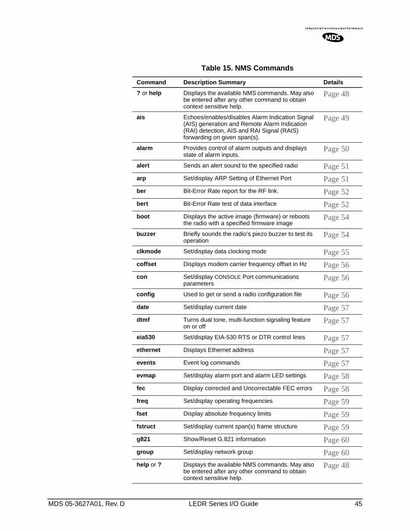
MDS 05-3627A01, Rev. D LEDR Series I/O Guide 45
Table 15. NMS Commands
Command Description Summary Details
? or help Displays the available NMS commands. May also be entered after any other command to obtain context sensitive help.
Page 48
ais Echoes/enables/disables Alarm Indication Signal (AIS) generation and Remote Alarm Indication (RAI) detection, AIS and RAI Signal (RAIS) forwarding on given span(s).
Page 49
alarm Provides control of alarm outputs and displays state of alarm inputs.
Page 50
alert Sends an alert sound to the specified radio Page 51
arp Set/display ARP Setting of Ethernet Port Page 51
ber Bit-Error Rate report for the RF link. Page 52
bert Bit-Error Rate test of data interface Page 52
boot Displays the active image (firmware) or reboots the radio with a specified firmware image
Page 54
buzzer Briefly sounds the radio’s piezo buzzer to test its operation
Page 54
clkmode Set/display data clocking mode Page 55
coffset Displays modem carrier frequency offset in Hz Page 56
con Set/display CONSOLE Port communications parameters
Page 56
config Used to get or send a radio configuration file Page 56
date Set/display current date Page 57
dtmf Turns dual tone, multi-function signaling feature on or off
Page 57
eia530 Set/display EIA-530 RTS or DTR control lines Page 57
ethernet Displays Ethernet address Page 57
events Event log commands Page 57
evmap Set/display alarm port and alarm LED settings Page 58
fec Display corrected and Uncorrectable FEC errors Page 58
freq Set/display operating frequencies Page 59
fset Display absolute frequency limits Page 59
fstruct Set/display current span(s) frame structure Page 59
g821 Show/Reset G.821 information Page 60
group Set/display network group Page 60
help or ? Displays the available NMS commands. May also be entered after any other command to obtain context sensitive help.
Page 48
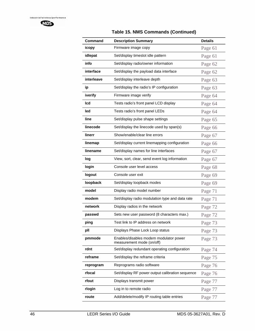
46 LEDR Series I/O Guide MDS 05-3627A01, Rev. D
icopy Firmware image copy Page 61
idlepat Set/display timeslot idle pattern Page 61
info Set/display radio/owner information Page 62
interface Set/display the payload data interface Page 62
interleave Set/display interleave depth Page 63
ip Set/display the radio’s IP configuration Page 63
iverify Firmware image verify Page 64
lcd Tests radio’s front panel LCD display Page 64
led Tests radio’s front panel LEDs Page 64
line Set/display pulse shape settings Page 65
linecode Set/display the linecode used by span(s) Page 66
linerr Show/enable/clear line errors Page 67
linemap Set/display current linemapping configuration Page 66
linename Set/display names for line interfaces Page 67
log View, sort, clear, send event log information Page 67
login Console user level access Page 68
logout Console user exit Page 69
loopback Set/display loopback modes Page 69
model Display radio model number Page 71
modem Set/display radio modulation type and data rate Page 71
network Display radios in the network Page 72
passwd Sets new user password (8 characters max.) Page 72
ping Test link to IP address on network Page 73
pll Displays Phase Lock Loop status Page 73
pmmode Enables/disables modem modulator power measurement mode (on/off)
Page 73
rdnt Set/display redundant operating configuration Page 74
reframe Set/display the reframe criteria Page 75
reprogram Reprograms radio software Page 76
rfocal Set/display RF power output calibration sequence Page 76
rfout Displays transmit power Page 77
rlogin Log in to remote radio Page 77
route Add/delete/modify IP routing table entries Page 77
Table 15. NMS Commands (Continued)
Command Description Summary Details
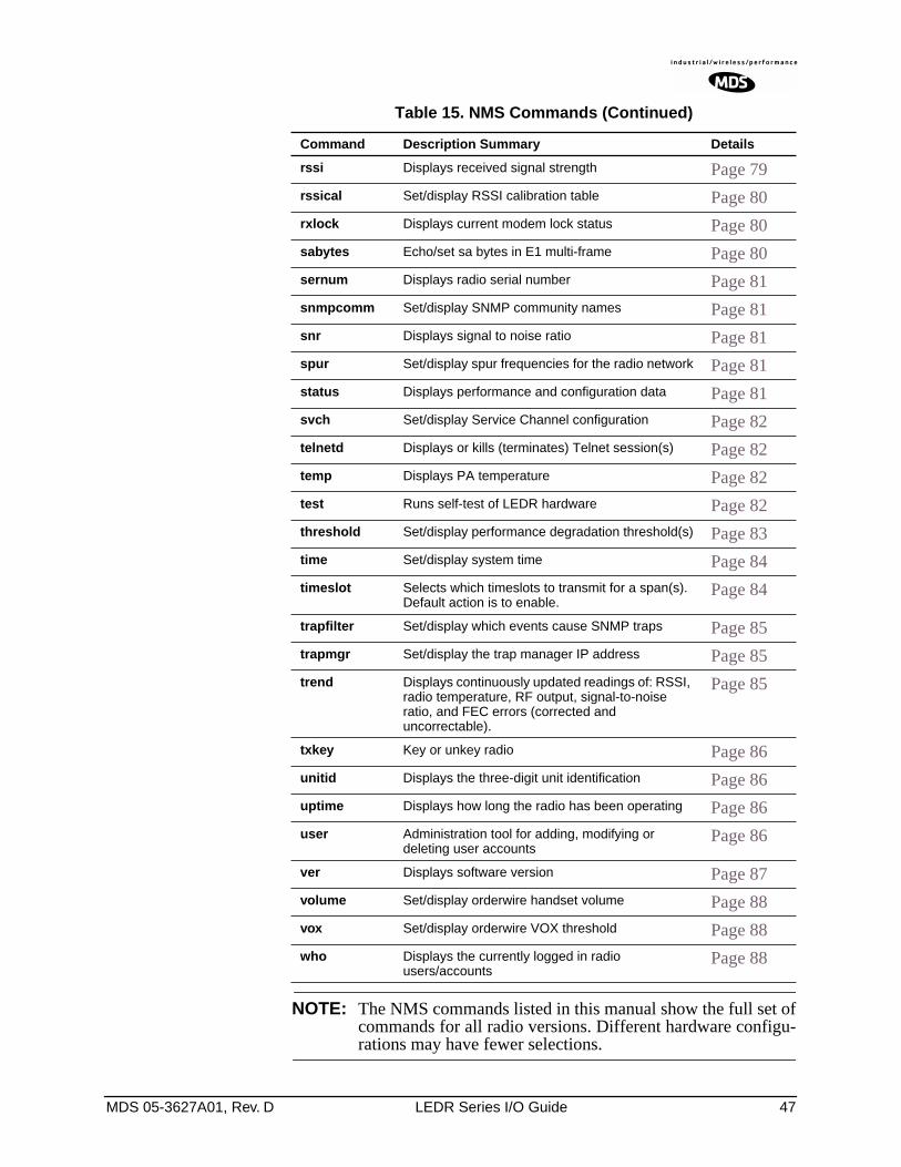
MDS 05-3627A01, Rev. D LEDR Series I/O Guide 47
NOTE: The NMS commands listed in this manual show the full set ofcommands for all radio versions. Different hardware configu-rations may have fewer selections.
rssi Displays received signal strength Page 79
rssical Set/display RSSI calibration table Page 80
rxlock Displays current modem lock status Page 80
sabytes Echo/set sa bytes in E1 multi-frame Page 80
sernum Displays radio serial number Page 81
snmpcomm Set/display SNMP community names Page 81
snr Displays signal to noise ratio Page 81
spur Set/display spur frequencies for the radio network Page 81
status Displays performance and configuration data Page 81
svch Set/display Service Channel configuration Page 82
telnetd Displays or kills (terminates) Telnet session(s) Page 82
temp Displays PA temperature Page 82
test Runs self-test of LEDR hardware Page 82
threshold Set/display performance degradation threshold(s) Page 83
time Set/display system time Page 84
timeslot Selects which timeslots to transmit for a span(s). Default action is to enable.
Page 84
trapfilter Set/display which events cause SNMP traps Page 85
trapmgr Set/display the trap manager IP address Page 85
trend Displays continuously updated readings of: RSSI, radio temperature, RF output, signal-to-noise ratio, and FEC errors (corrected and uncorrectable).
Page 85
txkey Key or unkey radio Page 86
unitid Displays the three-digit unit identification Page 86
uptime Displays how long the radio has been operating Page 86
user Administration tool for adding, modifying or deleting user accounts
Page 86
ver Displays software version Page 87
volume Set/display orderwire handset volume Page 88
vox Set/display orderwire VOX threshold Page 88
who Displays the currently logged in radio users/accounts
Page 88
Table 15. NMS Commands (Continued)
Command Description Summary Details
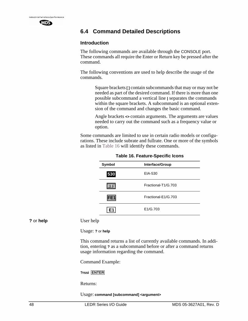
48 LEDR Series I/O Guide MDS 05-3627A01, Rev. D
6.4 Command Detailed Descriptions
Introduction
The following commands are available through the CONSOLE port. These commands all require the Enter or Return key be pressed after the command.
The following conventions are used to help describe the usage of the commands.
Square brackets [ ] contain subcommands that may or may not be needed as part of the desired command. If there is more than one possible subcommand a vertical line | separates the commands within the square brackets. A subcommand is an optional exten-sion of the command and changes the basic command.
Angle brackets <> contain arguments. The arguments are values needed to carry out the command such as a frequency value or option.
Some commands are limited to use in certain radio models or configu-rations. These include subrate and fullrate. One or more of the symbols as listed in Table 16 will identify these commands.
? or help User help
Usage: ? or help
This command returns a list of currently available commands. In addi-tion, entering ? as a subcommand before or after a command returns usage information regarding the command.
Command Example:
?rssi
Returns:
Usage: command [subcommand] <argument>
Table 16. Feature-Specific Icons
Symbol Interface/Group
EIA-530
Fractional-T1/G.703
Fractional-E1/G.703
E1/G.703
530
FT1
FE1
E1
ENTER
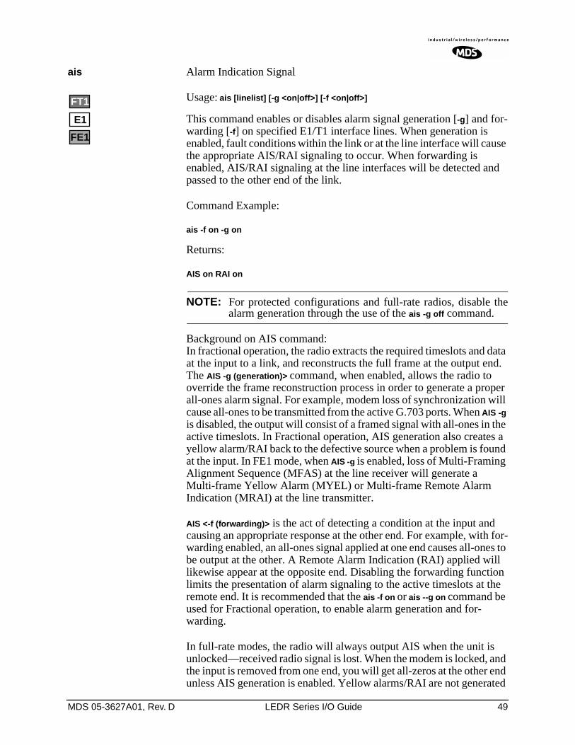
MDS 05-3627A01, Rev. D LEDR Series I/O Guide 49
ais Alarm Indication Signal
Usage: ais [linelist] [-g <on|off>] [-f <on|off>]
This command enables or disables alarm signal generation [-g] and for-warding [-f] on specified E1/T1 interface lines. When generation is enabled, fault conditions within the link or at the line interface will cause the appropriate AIS/RAI signaling to occur. When forwarding is enabled, AIS/RAI signaling at the line interfaces will be detected and passed to the other end of the link.
Command Example:
ais -f on -g on
Returns:
AIS on RAI on
NOTE: For protected configurations and full-rate radios, disable thealarm generation through the use of the ais -g off command.
Background on AIS command:In fractional operation, the radio extracts the required timeslots and data at the input to a link, and reconstructs the full frame at the output end. The AIS -g (generation)> command, when enabled, allows the radio to override the frame reconstruction process in order to generate a proper all-ones alarm signal. For example, modem loss of synchronization will cause all-ones to be transmitted from the active G.703 ports. When AIS -g is disabled, the output will consist of a framed signal with all-ones in the active timeslots. In Fractional operation, AIS generation also creates a yellow alarm/RAI back to the defective source when a problem is found at the input. In FE1 mode, when AIS -g is enabled, loss of Multi-Framing Alignment Sequence (MFAS) at the line receiver will generate a Multi-frame Yellow Alarm (MYEL) or Multi-frame Remote Alarm Indication (MRAI) at the line transmitter.
AIS <-f (forwarding)> is the act of detecting a condition at the input and causing an appropriate response at the other end. For example, with for-warding enabled, an all-ones signal applied at one end causes all-ones to be output at the other. A Remote Alarm Indication (RAI) applied will likewise appear at the opposite end. Disabling the forwarding function limits the presentation of alarm signaling to the active timeslots at the remote end. It is recommended that the ais -f on or ais --g on command be used for Fractional operation, to enable alarm generation and for-warding.
In full-rate modes, the radio will always output AIS when the unit is unlocked—received radio signal is lost. When the modem is locked, and the input is removed from one end, you will get all-zeros at the other end unless AIS generation is enabled. Yellow alarms/RAI are not generated
E1
FT1
FE1
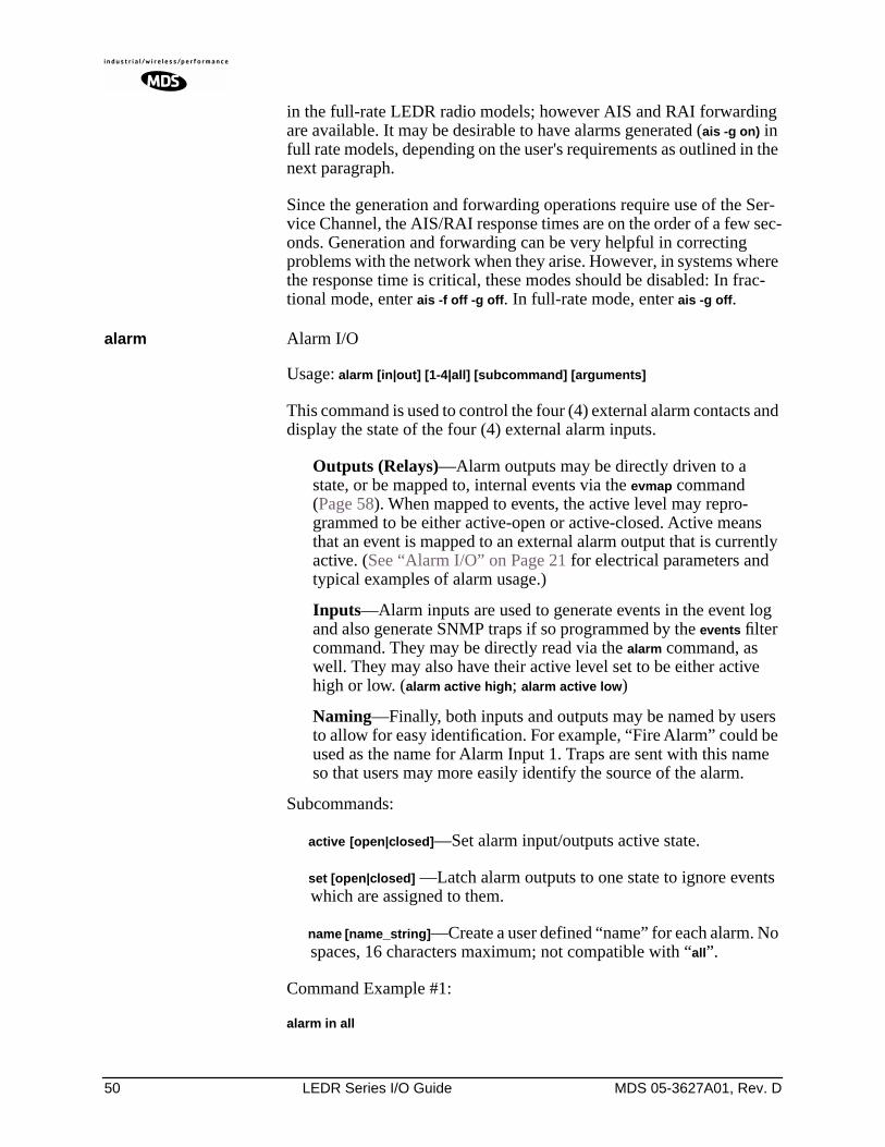
50 LEDR Series I/O Guide MDS 05-3627A01, Rev. D
in the full-rate LEDR radio models; however AIS and RAI forwarding are available. It may be desirable to have alarms generated (ais -g on) in full rate models, depending on the user's requirements as outlined in the next paragraph.
Since the generation and forwarding operations require use of the Ser-vice Channel, the AIS/RAI response times are on the order of a few sec-onds. Generation and forwarding can be very helpful in correcting problems with the network when they arise. However, in systems where the response time is critical, these modes should be disabled: In frac-tional mode, enter ais -f off -g off. In full-rate mode, enter ais -g off.
alarm Alarm I/O
Usage: alarm [in|out] [1-4|all] [subcommand] [arguments]
This command is used to control the four (4) external alarm contacts and display the state of the four (4) external alarm inputs.
Outputs (Relays)—Alarm outputs may be directly driven to a state, or be mapped to, internal events via the evmap command (Page 58). When mapped to events, the active level may repro-grammed to be either active-open or active-closed. Active means that an event is mapped to an external alarm output that is currently active. (See “Alarm I/O” on Page 21 for electrical parameters and typical examples of alarm usage.)
Inputs—Alarm inputs are used to generate events in the event log and also generate SNMP traps if so programmed by the events filter command. They may be directly read via the alarm command, as well. They may also have their active level set to be either active high or low. (alarm active high; alarm active low)
Naming—Finally, both inputs and outputs may be named by users to allow for easy identification. For example, “Fire Alarm” could be used as the name for Alarm Input 1. Traps are sent with this name so that users may more easily identify the source of the alarm.
Subcommands:
active [open|closed]—Set alarm input/outputs active state.
set [open|closed] —Latch alarm outputs to one state to ignore events which are assigned to them.
name [name_string]—Create a user defined “name” for each alarm. No spaces, 16 characters maximum; not compatible with “all”.
Command Example #1:
alarm in all
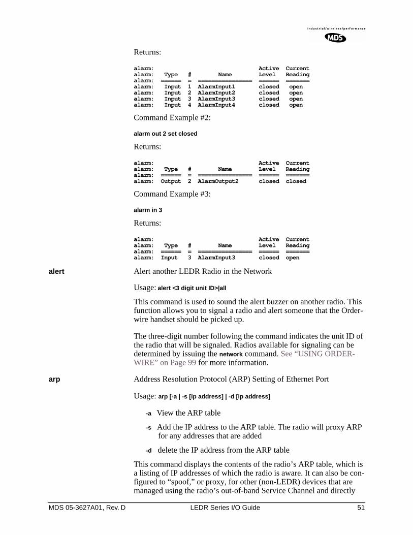
MDS 05-3627A01, Rev. D LEDR Series I/O Guide 51
Returns:
alarm: Active Currentalarm: Type # Name Level Readingalarm: ====== = ================ ====== =======alarm: Input 1 AlarmInput1 closed openalarm: Input 2 AlarmInput2 closed openalarm: Input 3 AlarmInput3 closed openalarm: Input 4 AlarmInput4 closed open
Command Example #2:
alarm out 2 set closed
Returns:
alarm: Active Currentalarm: Type # Name Level Readingalarm: ====== = ================ ====== =======alarm: Output 2 AlarmOutput2 closed closed
Command Example #3:
alarm in 3
Returns:
alarm: Active Currentalarm: Type # Name Level Readingalarm: ====== = ================ ====== =======alarm: Input 3 AlarmInput3 closed open
alert Alert another LEDR Radio in the Network
Usage: alert <3 digit unit ID>|all
This command is used to sound the alert buzzer on another radio. This function allows you to signal a radio and alert someone that the Order-wire handset should be picked up.
The three-digit number following the command indicates the unit ID of the radio that will be signaled. Radios available for signaling can be determined by issuing the network command. See “USING ORDER-WIRE” on Page 99 for more information.
arp Address Resolution Protocol (ARP) Setting of Ethernet Port
Usage: arp [-a | -s [ip address] | -d [ip address]
-a View the ARP table
-s Add the IP address to the ARP table. The radio will proxy ARP for any addresses that are added
-d delete the IP address from the ARP table
This command displays the contents of the radio’s ARP table, which is a listing of IP addresses of which the radio is aware. It can also be con-figured to “spoof,” or proxy, for other (non-LEDR) devices that are managed using the radio’s out-of-band Service Channel and directly
52 LEDR Series I/O Guide MDS 05-3627A01, Rev. D
connected at some point to a radio’s Ethernet port, or to a common hub with a LEDR radio. In other words, the radio network can be configured for seamless integration of other IP-manageable devices by responding to ARP requests and/forwarding IP traffic directed to those devices.
See the route command on Page 77 for information on other necessary configuration steps to allow for IP connectivity to LEDR radios and associated devices using the radio’s network-management channel.
ber Bit-Error Rate of the RF Link
Usage: ber
This command displays pre-FEC and post-FEC Bit-Error Rate (BER) between the LEDR radios in the first link.
NOTE: The BER measurement limit is 1E-8. For more reliable infor-mation on the link-error rate, use the g821 demod command.
bert Bit-Error Rate Test of Data Interface
Usage: bert [linelist] [-e [pattern] | -d | -i [error] | -lp | -le | stats]
bert is used for diagnostic purposes by causing the selected line of the FT1/E1 interface port lines to output a user-selectable pseudo-random bit sequence, either framed or unframed. This command also allows the user to measure the bit error rate, number of errors, etc. This command tests all T1/E1 timeslots without regard to the timeslot command’s con-figuration.
linelist—List of local line interfaces. Can be single line number or line-name (see linename command), comma-separated list of line numbers or linenames, a range of line numbers (for example: 1-4), or if linelist is not given, all lines will be tested.
NOTE: The hyphen is part of the argument string and must be included for the command to function.
Subcommands:
Control—
-e Enable bert generation/monitoring for line(s)
Can be immediately followed by the test pattern index value (See -lp below). If none is included in the command, the last-used pattern will be implemented.
-d Disable bert generation/monitoring for line(s)
-i Inject error. Index specifying type of error to inject. If no error is specified, last error selected is used.
E1
FT1
FE1
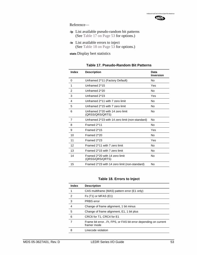
MDS 05-3627A01, Rev. D LEDR Series I/O Guide 53
Reference—
-lp List available pseudo-random bit patterns (See Table 17 on Page 53 for options.)
-le List available errors to inject(See Table 18 on Page 53 for options.)
stats Display bert statistics
Table 17. Pseudo-Random Bit Patterns
Index Description Data Inversion
0 Unframed 2^11 (Factory Default) No
1 Unframed 2^15 Yes
2 Unframed 2^20 No
3 Unframed 2^23 Yes
4 Unframed 2^11 with 7 zero limit No
5 Unframed 2^15 with 7 zero limit No
6 Unframed 2^20 with 14 zero limit (QRSS/QRS/QRTS)
No
7 Unframed 2^23 with 14 zero limit (non-standard) No
8 Framed 2^11 No
9 Framed 2^15 Yes
10 Framed 2^20 No
11 Framed 2^23 Yes
12 Framed 2^11 with 7 zero limit No
13 Framed 2^15 with 7 zero limit No
14 Framed 2^20 with 14 zero limit (QRSS/QRS/QRTS)
No
15 Framed 2^23 with 14 zero limit (non-standard) No
Table 18. Errors to Inject
Index Description
1 CAS multiframe (MAS) pattern error (E1 only)
2 Fs (T1) or MFAS (E1)
3 PRBS error
4 Change of frame alignment, 1 bit minus
5 Change of frame alignment, E1, 1 bit plus
6 CRC6 for T1, CRC4 for E1
7 Frame bit error...Ft, FPS, or FAS bit error depending on current framer mode
8 Linecode violation
54 LEDR Series I/O Guide MDS 05-3627A01, Rev. D
Background information on bert command:
The bit error-rate test command, bert, is used to evaluate the link between the LEDR data interface and the customer premises equipment (CPE). When used, the LEDR radio will send a test pattern out of the LEDR FT1/E1 Data Interface lines towards the CPE while simulta-neously attempting to receive the same pattern back from the CPE. For example, you can loopback the CPE’s external data device’s I/O, then issue a bert command to the LEDR radio to check the integrity of the wire connection. The test pattern can be user-selectable. (See bert com-mand Options above for further information.)
NOTE: The bert command will not test or evaluate the integrity of theLEDR radio link. (See “BENCH TESTING OF RADIOS” onPage 122 for further information.)
NOTE: When operating FT1 or FE1 interfaces, this command tests allT1/E1 timeslots without regard to the timeslot command’sconfiguration.
boot Boot from Active/Archive Software
Usage: boot [<1|2|-s|-o>]
This command is used to view or change the radio’s active software image. If boot is entered alone, the currently active firmware image (1 or 2) is displayed. A selection of 1 or 2 after the command (e.g., boot 2) ini-tiates a reboot from that image. (A message appears to confirm that you wish to reboot the radio firmware.) Upon reboot, the radio and all radio functions are restarted in a manner similar to turning the radio power off and then on again. The radio is taken out of service until it re-initializes, and the link loses synchronization until the reboot process completes and the demodulators at both ends reacquire the radio signals.
A choice of software images allows booting an alternate version of radio software. The ability to have two radio-resident software images allows radio software reprogramming over-the-air and the ability to restore operation to the original software if required.
Subcommands:
1 Boot from Image 1
2 Boot from Image 2
-s Boot from the active (same) image
-o Boot from the inactive (other) image
buzzer Buzzer
Usage: buzzer
MDS 05-3627A01, Rev. D LEDR Series I/O Guide 55
This command briefly sounds the radio’s piezo buzzer for testing. It should be used only from the CONSOLE Port.
Example Response:
buzzer: Starting testbuzzer: Test complete
clkmode Clock Mode (Subrate Radios Only)
Usage: clkmode [<internal|exttx|looped|extdce>]
This command displays or sets the source of the radio’s transmit clock. For synchronization purposes, several different clocking schemes can be used. See Table 10 on Page 23 for the combinations of radio band-width, data rates and modulation types that are available for subrate radios. Table 11 on Page 24 shows the combinations available for full rate radios.
Subcommands:
internal—Internal oscillator sources TC; RC derived from far end of radio link (default).exttx—ETC accepted from external equipment on EIA-530 inter-face; RC derived from far end of radio link.looped—Recovered RF (RX) clock; TC is synchronized to RC; RC is derived from far end of radio link. Note: Do not use looped clocks at both ends of any radio link.extdce—ETC and ERC are accepted as inputs on the EIA-530 interface.
NOTE: Earlier versions of the software may display the Clock Modeas NORMAL instead of INTERNAL.
Firmware Version 2.4.0 and Later – Use the clkmode command to determine which port has been selected to drive the timing at the inter-face.
Firmware Version 2.3.1 and Earlier – This command allows the var-ious possible clock sources to be prioritized. As timing sources become available, the highest-priority source will be chosen by the system. If attaching to the network or equipment that provides timing, a universal form of the command would be clkmode 1 2 3 4 internal. If attaching to equipment that will provide looped-back timing, a universal form of the command would be clkmode remote internal. If both ends of the link pro-vide looped timing, the internal clock source should be selected at one end by entering clkmode internal. Note that at least one end of the link should have either network or internal timing selected.
530
E1
FT1
56 LEDR Series I/O Guide MDS 05-3627A01, Rev. D
NOTE: Firmware versions 2.3.1 and earlier, require that this parameter be properly configured for correct operation of the link. More recent firmware versions do not require that this item be manually configured. However, the clkmode command may still be used to determine which port is being used to drive the timing.
Firmware Version 3.0.0 and Later– The clkmode command applies only to the EIA-530 interface.
coffset Carrier Offset of Radio Modem
Usage: coffset
This command displays the Modem Carrier Frequency Offset.
con Console port configuration on LEDR front panel
Usage: con (baud [300|1200|2400|4800|9600|19200|38400|115200]) (parity [none|even|odd])
This command sets or displays the CONSOLE Port’s operating parame-ters. The CONSOLE Port data rate is set or displayed using the baud sub-command. The parity is set or displayed using the parity subcommand.
The default setting is 9600 bps, no parity, 8 data bits and 1 stop bit.
config Configuration
Usage: config [get|send|getall] [filename|console] [hostIP]
This command is used to get or send a radio configuration file.
The radio stores its configuration data in a file that you can download using the config send command. The output can be directed to a file or to the NMS window, either in a Telnet session or a serial NMS session. The config send command allows sending the configuration file over the Ethernet management channel and storing it on a PC running a TFTP server.
Subcommands:
send—Upload entire radio configuration file to host (includes all radio-specific data)get—Download radio configuration file from host (DOES NOT download radio-specific data)getall—Download entire radio configuration file from host (including all radio-specific data)
Radio-specific data includes IP address, network settings, frequencies, target power thresholds, calibration data, and IP routing table.
Command Example: config send config.txt 192.168.1.14
MDS 05-3627A01, Rev. D LEDR Series I/O Guide 57
This sends the configuration file to a TFTP server running on host 192.168.1.14 and stores it as a file called config.txt.
date Date
Usage: date [MM/DD/YYYY]
This command sets or displays the date and time of the radio’s internal real-time clock. The real time clock operates from an internal lithium battery so it is running even if the radio has no DC power connected. The date format may also be set or displayed from this screen for one of three formats: U.S., European, or generic.
The real time clock is fully compliant with year 2000 standards.
Subcommands: date format [<1-3>]
Date Format 1: mm/dd/yyyy (All numbers)
Date Format 2: dd/mm/yyyy (All numbers)
Date Format 3: dd-MON-yyyy (English abbreviation of month)
Example Response: date: 07-JUN-1999 08:11:30
dtmf Dual Tone, Multi-Function tone selection
Usage: dtmf [on|off]
This command is used to turn the DTMF signaling feature on or off.
eia530 EIA-530 selection
Usage: eia530 [rts <on|off>] [dtr <on|off>]
This command is used to set or display the status of the EIA-530 control lines (RTS and DTR).
ethernet Ethernet Port’s Hardware Address
Usage: ethernet
This command displays the fixed hardware address of the radio’s Ethernet port. This address is globally unique; it is assigned at the fac-tory and cannot be changed.
events Events
Usage: events [subcommand] [<arguments>]Subcommands: pending
filter [event#] [count]initdesc [<event#>]
530
58 LEDR Series I/O Guide MDS 05-3627A01, Rev. D
This command allows viewing the pending events (pending), sup-pressing the notification of particular events (filter), initializing events processing (init) and display of event descriptions (desc). To turn off log-ging (notification in the event log) for a particular event, the filter count value should be set to zero.
Events 135-138 are remote alarm in [1-4], respectively, which reflects the event state of the alarm in [1-4] of the remote-located radio at the other end of the RF link.
Example Response:
events events: -DEMOD_ACQUISITION (Event #27)events: Event#0 Filter count=1events init: The event log has been re-initializedevents desc: Event#40 Description-IO2_DIG_REM_LPBACK
evmap Event Mapping (for Alarm Output and LEDs)
Usage: evmap [subcommand] [event #] [arguments]
This command sets or displays which radio system events cause alarm indications on the front panel LEDs or the rear panel ALARM I/O con-nector. The user can rename the alarm events, but they cannot be deleted, nor can new ones be created.
The subcommands specify which output will be asserted (led or aout) upon occurrence of an event #. Multiple outputs can be specified with spaces between them. The dump option allows determining the current event mapping for all of the events or, optionally, a specified numeric range of events.
Events 135-138 are remote alarm in [1-4], respectively, which reflects the event state of the alarm in [1-4] of the remote-located radio at the other end of the RF link. Use the event filter counter to enable each particular event. Use evmap and map to alarm output contact when necessary.
Subcommands are listed below:
led [ioalarm|txalarm|rxalarm|alarm|none]—Maps front panel LED(s) to an event.aout [none|1|2|3|4]—Maps an alarm output(s) to an event.dump [<range>]—Display the LED and alarm output mappings for all events.
See Figure 8 for reference to the Front Panel LEDs. Refer to Alarm—Rear Panel on Page 132 for the pinouts of the ALARM I/O connector and Disabling the Front Panel Alarm LED for Unused E1 Option Ports on Page 88 for further information.
fec Forward Error Correction Statistics
Usage: [fec <clear>]
MDS 05-3627A01, Rev. D LEDR Series I/O Guide 59
This command displays corrected bytes and uncorrectable FEC block errors.
Example Response: fec: 1812992 Correctable Bytesfec: 2 Uncorrectable Blocks
freq Frequency of TX & RX Channel
Usage: freq [<tx|rx>] [<freq>] [<freq>]
This command sets or displays the transmit and receive frequency.
Example Response: freq TxFreq: 942175000 Hzfreq RxFreq: 944175000 Hz
fset Frequency Setting
Usage: fset [<min freq>] [<max freq>]
This command sets the absolute frequency limits of the transmitter and receiver.
Example Response: fset Tx MinFreq: 1350000000 Hzfset Tx MaxFreq: 1535000000 Hzfset Rx MinFreq: 1350000000 Hzfset Rx MaxFreq: 1535000000 Hz
fstruct Frame Structure
Usage: fstruct [linelist] [mode <0-7|none>]
This command is used to set or display the span(s) frame structure. The [linelist] variable represents a list of line interfaces. This entry can be either a single line number or line name (see linename command), a comma-separated list of line numbers or line names, a range of line numbers (i.e., 1-4), or if linelist is not given all lines.
In general, this parameter should be configured to match the frame structure used by the customer premises equipment. The fstruct com-mand also controls the generation of performance report messages in ESF modes. In E1 radios, an unframed mode is available by issuing the command fstruct mode 8.
In Fractional-E1 mode timeslot 0 is always sent, and for fstruct modes 4 through 7, timeslot 16 must be added to the payload list for proper oper-ation.
E1
FT1
FE1
60 LEDR Series I/O Guide MDS 05-3627A01, Rev. D
Table 19 shows a list of line mode values for T1 interfaces and Table 20 for E1 interfaces.
g821 G.821 Information
Usage: demod io1|io2|io3|io4|all [clr]
This command is used to show or reset the radio’s G.821 information.
The LEDR family of radios support the ITU G.821 recommendation for display of four categories of statistical availability information: avail-able seconds, errored seconds, severely errored seconds, and unavail-able seconds.
Example Response: Demodulator: ERROR FREESavail: 1036Sunavail: 0ES: 0SES: 0
group Group Number in LEDR System
Usage: Group [<0-99>]
Table 19. T1 Frame’s Line Mode Values
Value Mode
0 FT only (default)
1 ESF
2 ESF + PRM
3 SF
4 SF + JYEL
5 ESF + CRC
6 ESF + CRC +PRM
Table 20. E1 Frame’s Line Mode Values
Value Mode
0 FAS only (default)
1 FAS + BSLIP
2 FAS + CRC
3 FAS + CRC + BSLIP
4 FAS + CAS
5 FAS + CAS + BSLIP
6 FAS + CRC + CAS
7 FAS + CRC + CAS + BSLIP
8 Raw, unframed, transparent mode.*
* Mode 8 is forbidden in fractional modes.
E1
FT1
FE1
MDS 05-3627A01, Rev. D LEDR Series I/O Guide 61
This command sets or displays the network group in which the radio is operating.
Example Response:group: 1
In a typical system, all the radios would operate in the same group, allowing the flow of network-management and orderwire activity between radios and from one radio link to any other in the system. At a repeater site, all radios must be set to the same “group number” (and not group zero) for this flow of information to take place. Setting group numbers differently in repeater systems isolates links from each other from a network-management perspective, allowing segmenting net-works and controlling the flow of network-management information. Across a radio link, groups can differ from each other; only radios phys-ically connected by Ethernet cables to each other or to the same hub must have the same group number to intercommunicate.
Setting a radio’s group to zero prohibits all network management traffic from flowing to and from that radio’s Ethernet port.
help or ? User help
Usage: help or ?
This command can be used alone, to list all available commands, or with a specific command, to provide syntax assistance. Entering help before or after a command will display the usage and possible subcommands of the command.
icopy Image Copy
Usage: icopy [<app|dsp|fpga|scripts>]
This command is used to copy the active software image to the inactive software image.
Each radio stores two independent firmware files that control the radio’s operation. The radio uses one of the files as the active software, which is running. The other software file is inactive and is not running. The ability to have two firmware images allows firmware reprogramming to be done over-the-air and provides the ability to restore operation to the original software if required. The icopy command allows copying all, or a selected subset, of the regions of the active image to the inactive image area. This is typically used to update the inactive image after loading new firmware and rebooting the radio from the new image.
To view or change the active firmware image see “boot” on Page 54.
idlepat Idle Pattern
Usage: idlepat [<linelist>] [slots <slotlist>] <pattern>
E1
FT1
FE1
62 LEDR Series I/O Guide MDS 05-3627A01, Rev. D
This command is used to set or display the bit-pattern used in the idle timeslots. Some equipment requires a particular pattern. To set the bits to all ones, use the command idlepat ff. To set the bits to a zero followed by seven ones, use the command idlepat 7f. This command does not apply to subrate models.
Argument Definitions:
linelist—Represents a list of line interfaces. It can consist of a single line number or linename, a comma separated list of line num-bers or line names, a range of line numbers (i.e., 1–4) or, if linelist is not given, all lines. See Table 19 on Page 59 for a list of line numbers.
slotlist—A list of timeslots consisting of a single slot number, comma separated list of slot numbers, or a range of slot num-bers (i.e., 2-8).
pattern—A 2 hex digit value (default value is 17).
info Information as Selected by User
Usage: info [<owner|description|contact|name|location>] [<string>]info clear [<owner|description|contact|name|location>]
This command is used to program information into (or clear it from) radio memory that is particular to the radio site or installation. The infor-mation is intended for identification and memorandum needs.
Five text fields are provided. The owner’s name string is limited to 10 characters. The description, contact, location, and name text fields are limited to 254 characters. Any standard, printable ASCII characters are allowed. The description field is programmed at the factory and is not user-definable.
To display the owner’s name text field enter info owner. To display the contact information enter info contact. To display the name information enter info name. To display the location information enter info location.To display all the parameters enter info.
To change the info text, enter text after info owner or other info field name.
interface Interface for User Data
Usage: interface [e1|t1|530]
This command is used to set or display the payload data interface. If an optional data interface board is installed, the user may select between the T1 or E1 interface modes. The system will recommend a reboot and provide a prompt to do so. This command must be properly set, or no communication will be possible.
E1
FT1
530
FE1
MDS 05-3627A01, Rev. D LEDR Series I/O Guide 63
Example Response:
interface Line: e1
NOTE: 1E1 through 4E1 data rates are not supported when using theEIA-530 interface. The maximum EIA-530 data rate is 768kbps.
interleave Interleave
Usage: interleave [1-12]
This command is used to set or display the interleave depth. The depth range is 1–12 with settable values of 1, 2, 3, 4, 6 and 12. Default setting for Subrate is 2, Default setting for Fullrate is 12. The interleave setting must match at both ends of a radio link, or the link cannot synchronize regardless of any other radio settings or signal strength. Larger inter-leave settings cause longer link latency; in latency-sensitive applica-tions, interleave value should be reduced to as small a value as is possible while maintaining good link performance (See the g821 demod command).
Example Response:
interleave: 1
Background:
In digital communications, interference often occurs in the form of short noise bursts. These bursts normally corrupt a series of consecutive bits.
Interleaving is a digital algorithm that allows Forward Error Correction (FEC) to better handle bursts of noise. Interleaving reorders the data so that the symbols that would normally be neighbors in a given block are spread among multiple blocks. FEC works on a block of data of a spe-cific size and can properly correct errors as long as the number of errors is small enough. With interleaving, the number of errors that occur within a single block is reduced, thereby allowing the FEC to more effectively correct burst errors.
The value of the interleaver function should not be changed unless there are latency limitations for the radio link. If low latency is required, then the interleave can be changed, but the ability to correct for the influence of burst-noise on the BER will be reduced.
ip Internet Protocol Settings
Usage: ip [subcommand] [<argument>]
64 LEDR Series I/O Guide MDS 05-3627A01, Rev. D
Subcommands:
address [x.x.x.x]
netmask [x.x.x.x]
gateway [x.x.x.x]
IP port [ETH|AIR]
This command sets or displays the Internet Protocol (IP) settings for the LEDR radio. The subcommands allow you to set the IP address, IP net-mask, IP gateway, or IP port. The port setting determines whether IP com-munication to and from a particular radio occurs over the radio link or via a PC (or other networked device, such as a router) directly connected to the radio’s ETHERNET port. See “Network” on Page 39 for additional information.
Example Response: IP Address: 10.2.142.143IP Netmask: 255.255.0.0IP Gateway: 0.0.0.0IP Port: ETH
iverify Image Integrity Verification
Usage: iverify [image <1|2>] [<app|dsp|fpga|scripts>]
This command is used to determine the data integrity of the two firm-ware image files that reside in the radio. (See also icopy, above.)
Example Response:
iverify: Image has been verified
lcd Liquid Crystal Display (LCD) Test
Usage: lcd [<on|off|restore>]
This command starts a two-part test of the radio’s front panel LCD. When lcd is first entered, the display should appear with all blocks black. When the key is pressed, the screen should change to com-pletely blank.
led Light Emitting Diode test (Front Panel LEDs)
Usage: led [<alarm|rxalarm|txalarm|ioalarm|all|restore>] [<on|off>]
This command is used to test the front panel LEDs. If no argument is given, all front panel LEDs (except POWER) should flash in sequence. Press Control-C to end the test. (See “Disabling the Front Panel Alarm LED for Unused E1 Option Ports” on Page 88 for further information.)
Command Example:
led alarm on
RETURN
MDS 05-3627A01, Rev. D LEDR Series I/O Guide 65
Returns:
led: Alarm LED ON
line Attributes of lines (cables) used with the radio’s T1 or E1 Interface.
This command is used to set or display the internal pulse template selec-tion used by the LEDR interface to compensate for signal distortion cre-ated by various lengths and types of interface cables.
The [linelist] variable represents a list of line interfaces. It can consist of a single line number or line name, a comma-separated list of line num-bers or line names, a range of line numbers (i.e., 1–4), or if linelist is not given all lines will be displayed. See Table 19 on Page 59 for a list of line numbers.
Usage For T1: line [linelist] [cable length<0–4>] [spec]
T1 interfaces require setting of a minimum of two variables: ITU cable specification and cable length. Table 21 shows the specification options and Table 22 lists values used for various lengths of standard 100 Ω twisted pair cables
Table 21. ITU Cable Specifications—Subcommand [spec]
Usage For E1: line [linelist] [spec]
The only cable specification needed for E1 is the ITU cable type. Table 23 lists the specification values for two standard 120 Ω ITU-T G.703 cables
Table 23. E1 Cable Specifications—Subcommand [spec]
Specification
g.775 (Default)
i.431
FT1
E1
FE1
FT1
Table 22. Cable Length Values—Subcommand [cable length]
Value Line Length (Meters) Line Length (Feet)
0 0.3 to 40 (default) 1 to 133 feet (default)
1 40 to 81 133 to 266
2 81 to 122 266 to 399
3 122 to 163 399 to 533
4 163 to 200 533 to 655
Specification
g.775 (Default)
i.431
E1
FE1
66 LEDR Series I/O Guide MDS 05-3627A01, Rev. D
Command Example:
LEDR> line
Returns:
line LINE1 cable: ITU-T G.703 120 Ω Twisted Pairspec: i.431
line LINE2 cable: ITU-T G.703 120 Ω Twisted Pairspec: g.775
line LINE3 cable: ITU-T G.703 120 Ω Twisted Pairspec: g.775
line LINE4 cable: ITU-T G.703 120 Ω Twisted Pairspec: g.775
linecode Line Code
Usage: linecode [linelist] [B8ZS|AMI|HDB3]
This command sets or displays the radio’s linecode (T1: B8ZS or AMI; E1: HDB3 or AMI).
The [linelist] variable represents a list of line interfaces. It can consist of a single line number or line name, a comma-separated list of line num-bers or line names, a range of line numbers (i.e., 1–4), or if linelist is not given all lines will be displayed. See Table 19 on Page 59 for a list of line numbers.
The most typical Fractional-T1 selection is to choose B8ZS for all ports by entering linecode b8zs and E1 interfaces choose HDB3 for all ports by entering linecode hdb3.
Example Response:
linecode: HDB3
linemap Line Mapping
Usage: linemap [maplist]
This command is used to set or display the current span mapping con-figuration for E1 and T1 configurations. The maplist variable consists of from 1 to 4 alpha-numeric characters specifying line interface to span mapping. Valid numbers are 1–4. Valid span characters are a–d.
Example: Entering linemap 1d 2b 3a 4c causes the following:
maps line 1 to span dmaps line 2 to span bmaps line 3 to span amaps line 4 to span c
E1
FT1
FE1
E1
FT1
FE1
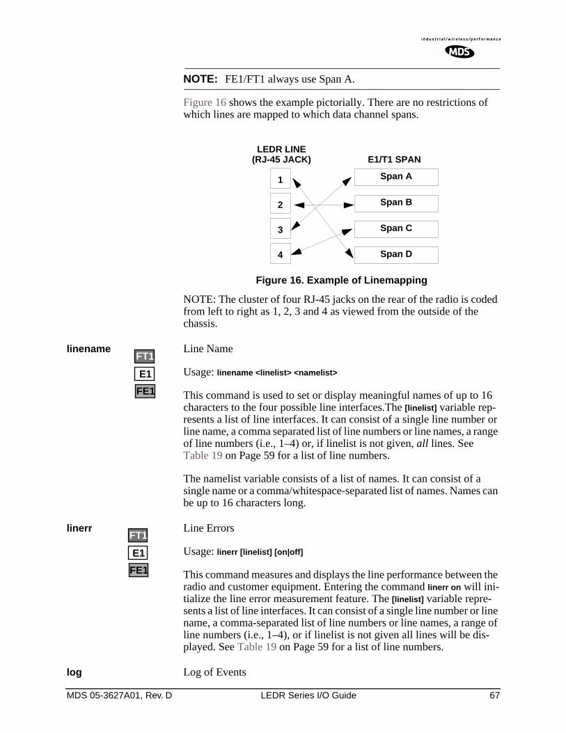
MDS 05-3627A01, Rev. D LEDR Series I/O Guide 67
NOTE: FE1/FT1 always use Span A.
Figure 16 shows the example pictorially. There are no restrictions of which lines are mapped to which data channel spans.
Invisible place holder
Figure 16. Example of Linemapping
NOTE: The cluster of four RJ-45 jacks on the rear of the radio is coded from left to right as 1, 2, 3 and 4 as viewed from the outside of the chassis.
linename Line Name
Usage: linename <linelist> <namelist>
This command is used to set or display meaningful names of up to 16 characters to the four possible line interfaces.The [linelist] variable rep-resents a list of line interfaces. It can consist of a single line number or line name, a comma separated list of line numbers or line names, a range of line numbers (i.e., 1–4) or, if linelist is not given, all lines. See Table 19 on Page 59 for a list of line numbers.
The namelist variable consists of a list of names. It can consist of a single name or a comma/whitespace-separated list of names. Names can be up to 16 characters long.
linerr Line Errors
Usage: linerr [linelist] [on|off]
This command measures and displays the line performance between the radio and customer equipment. Entering the command linerr on will ini-tialize the line error measurement feature. The [linelist] variable repre-sents a list of line interfaces. It can consist of a single line number or line name, a comma-separated list of line numbers or line names, a range of line numbers (i.e., 1–4), or if linelist is not given all lines will be dis-played. See Table 19 on Page 59 for a list of line numbers.
log Log of Events
3
4
2
1 Span A
Span B
Span C
Span D
LEDR LINEE1/T1 SPAN(RJ-45 JACK)
E1
FT1
FE1
E1
FT1
FE1
68 LEDR Series I/O Guide MDS 05-3627A01, Rev. D
Usage: log [subcommand] [<argument>]
Subcommands: view [critical|major|minor|inform]clearsend [filename] [hostIP]
This command is used to display and manage the event log file. Without a subcommand, the complete log file will be displayed one page at a time. If you are interested in less than the full report, use one of the fol-lowing subcommands:
view—Sets or displays the types of events to be displayed.
clear—Resets the event log and purges all events from memory.
send—Uploads the event log information to an IP address using TFTP protocol in a way similar to the config command. (See config command on Page 56.)
NOTE: When setting up a link for the first time, after powering up theunit, you may want to clear the event log. After logging in asSUPER, enter the command log clear.
login Log into the radio’s CONSOLE port
Usage: login [username]
This command allows access to configuration and diagnostics informa-tion as allowed by the radio system administrator. You can shorten the login sequence by following the login command with the user/account name (username).
Example:
LEDR> login
Returns:
Username>
Type: fieldserv (or appropriate user name)
Returns:
Password>
Type: (password)
NOTE: User names and passwords must not exceed eight charactersand are case sensitive. Do not use punctuation marks.
See user command on Page 86 for more information on user access levels.
MDS 05-3627A01, Rev. D LEDR Series I/O Guide 69
NOTE: Only one user can be logged in through the CONSOLE Port ata time. Any new login will close the previous user/account.Other users can login simultaneously through the ETHERNETPort or front panel.
logout Logout of the LEDR radio
Usage: logout
This command is used to log out a user.
Subcommands:
loopback Loopback Functions
The loopback command is used to set or display the loopback mode that can be used for diagnostic purposes. Entering loopback without any parameters displays the current loopback mode.
Various data loopback modes can be used for diagnostic purposes. To loop back Line Interface 1 towards itself, use loopback iol 1. To loop back all line interfaces towards themselves and test the T1 option, use loop-back local. To loop back all data at the remote site towards the RF path, use loopback remote.
Entering loopback without any parameters displays the current loopback mode.
Usage 1 for Fractional-T1:
loopback [none|rf|local|remote|iol [linelist]|ior [linelist] <timeout>]
Usage 1 Subcommands:
iol—The iol subcommand, for “I/O local,” refers to the local line loop-back.
local—Enables a local digital loopback mode. With this test, incoming bits on the EIA-530 interface are sent back out the radio’s DATA con-nector before the modem module. This can be used to verify proper interconnection between the radio and the connected equipment. None of the radio’s RF circuitry is involved in this test. (This description covers only EIA-530 operation.)
For T1/E1 operation, the local subcommand enables a local digital MUX loopback in the radio transceiver’s FT1 Interface Board before going out to the main transceiver board.
none—Disables all loopback operation. This is the mode for normal point-to-point operation.
E1
FT1
FE1
70 LEDR Series I/O Guide MDS 05-3627A01, Rev. D
remote—EIA-530 Operation: Instructs the radio at the other end of the link to “echo” all of the data it receives. This is an effective way of testing the entire communications system, including the transmission path over the air. (In the event of a communications failure with the remote radio, the message “Remote Error” is displayed, and no loop-back mode is selected.
T1/E1 Operation: The remote subcommand mimics the ior subcommand described below.
rf—Enables an RF loopback mode. This mode allows testing of the local radio transceiver’s transmit and receive chain. The receiver is rechan-neled to the transmitter frequency.
NOTE: RF loopback testing is a valuable diagnostic tool, but it shouldnot be considered an exhaustive test of the transceiver. In somecases, interaction between the transmit and receivephase-locked loops (PLLs) can occur, causing erroneousresults during testing. Changing the transceiver’s RF outputsetting may resolve these problems. Also, in some configura-tions, insufficient signal strength for RF loopback testing mayexist.
In addition, on all LEDR radios except the LEDR 1400 Series,the transmit and receive frequencies must be within the samesubband for RF loopback to function.
Variables:
ior—An abbreviation for “I/O remote”, refers to the remote line loop-back. Remote loopback port selection is relative to the local port. The radio link will translate any line mapping to select the correct physical remote port to loop back, based on the selected local port.
linelist—Represents a list of local line interfaces. It can consist of a single line number or line name, a comma-separated list of line numbers or line names, a range of line numbers (i.e., 1–4), or if linelist is not given all lines. See Table 19 on Page 59 for a list of line numbers.
timeout—The timeout variable may be set between 0 minutes (never time out) and 60 minutes.
Usage 2: loopback [inb|outb] [linelist] [on|off] [-u <code>] [-d <code>]
Usage 2 (E1) subcommands:
inb—Refers to the inband loopback configuration.
outb—Refers to the outband Extended Super Frame (ESF) loopback configuration.
FT1
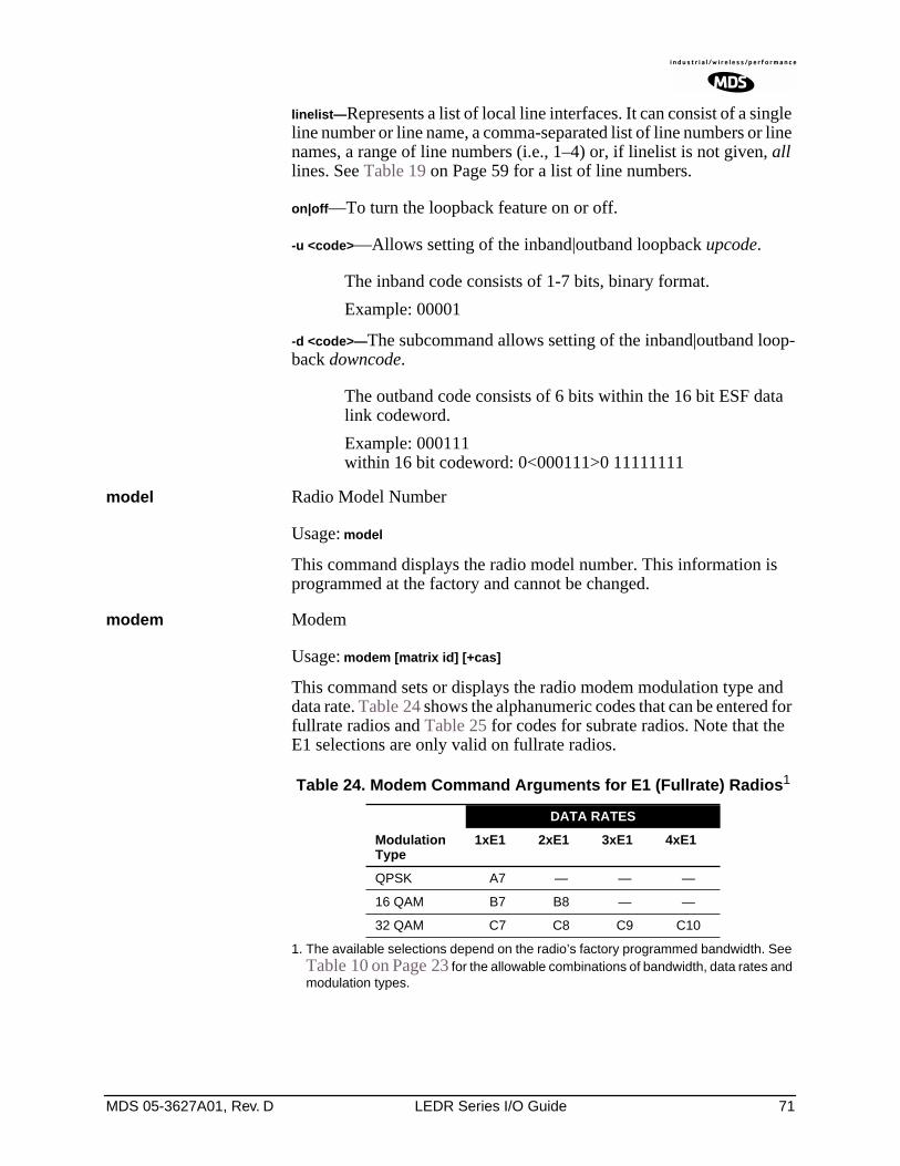
MDS 05-3627A01, Rev. D LEDR Series I/O Guide 71
linelist—Represents a list of local line interfaces. It can consist of a single line number or line name, a comma-separated list of line numbers or line names, a range of line numbers (i.e., 1–4) or, if linelist is not given, all lines. See Table 19 on Page 59 for a list of line numbers.
on|off—To turn the loopback feature on or off.
-u <code>—Allows setting of the inband|outband loopback upcode.
The inband code consists of 1-7 bits, binary format.
Example: 00001
-d <code>—The subcommand allows setting of the inband|outband loop-back downcode.
The outband code consists of 6 bits within the 16 bit ESF data link codeword.
Example: 000111within 16 bit codeword: 0<000111>0 11111111
model Radio Model Number
Usage: model
This command displays the radio model number. This information is programmed at the factory and cannot be changed.
modem Modem
Usage: modem [matrix id] [+cas]
This command sets or displays the radio modem modulation type and data rate. Table 24 shows the alphanumeric codes that can be entered for fullrate radios and Table 25 for codes for subrate radios. Note that the E1 selections are only valid on fullrate radios.
1. The available selections depend on the radio’s factory programmed bandwidth. See Table 10 on Page 23 for the allowable combinations of bandwidth, data rates and modulation types.
Table 24. Modem Command Arguments for E1 (Fullrate) Radios1
DATA RATES
Modulation Type
1xE1 2xE1 3xE1 4xE1
QPSK A7 — — —
16 QAM B7 B8 — —
32 QAM C7 C8 C9 C10
72 LEDR Series I/O Guide MDS 05-3627A01, Rev. D
1. The available selections depend on the radio’s factory programmed bandwidth. See Table 10 on Page 23 for the allowable combinations of bandwidth, data rates and modulation types.
Command Examples: To set 32 QAM with 1xE1, enter modem C7
To set 16 QAM/384 kbps, enter modem B4
Special-Order Argument
NOTE: The cas command functions only in radios equipped witheither the FT1 or FE1 Interface and user firmware of revision3.0 or higher.
cas—Set or display the Channel Associated Signaling (CAS) status for Fractional-T1 or Fractional-E1 operation. The available selections are
modem +cas (on) and modem -cas (off). This command provides for FT1 Robbed-Bit Signaling bits to pass over the link. In the FE1 case, this command, in conjunction with the fstruct command, ensures the proper handling of the timeslot 16 signaling bid.
network Network
Usage: network
This command displays the radios that can be reached via the Service Channel for Orderwire and Element Management System (EMS) diag-nostics.
Example Response:
passwd Password
Usage: passwd
Table 25. Modem Command Arguments for EIA-530 & FT1 (Subrate) Radios1
DATA RATES
Modulation Type
64 kbps
128 kbps
256 kbps
384 kbps
512 kbps
768 kbps
QPSK A1 A2 A3 — — —
16 QAM B1 B2 B3 B4 B5 B6
32 QAM — — — — — C6
FE1
FT1
Network Address10.2.142.14810.2.200.196
Netmask
255.255.0.0255.255.0.0
RFHops01
EthernetHops00
Receivedon PortLPBKAIR
OwnerTech Serv 1Tech Serv 2
MDS 05-3627A01, Rev. D LEDR Series I/O Guide 73
This command is used to change the password for the user currently logged in. A maximum of 8 characters is allowed, and it is case sensi-tive.
ping Ping IP Address (Send ICMP Echo Request)
Usage: ping [ip address] [reps]
This command is used to verify the accessibility of any IP address on the network to determine availability and measure network response time. This command requires proper IP Routing and IP connectivity.
ipaddress—IP address to which you will send the request
reps - Number of requests-to-send (default = 1, maximum = 1000)
Example:
LEDR> ping 10.2.233.12 5
Example Response:
PING 10.2.233.12: 56 data bytes64 bytes from 10.2.233.12: seq=1, ttl=255, rtt=49ms64 bytes from 10.2.233.12: seq=2, ttl=255, rtt=6ms64 bytes from 10.2.233.12: seq=3, ttl=255, rtt=9ms64 bytes from 10.2.233.12: seq=4, ttl=255, rtt=33ms64 bytes from 10.2.233.12: seq=5, ttl=255, rtt=12ms
pll Phase Locked Loop
Displays current TX & RX frequencies, and TX/RX PLL status.
Example Response:
pll:
Tx Freq = 438075000 Hz, Rx Freq = 428075000Tx PLL Status: LockedRx PLL Status: Locked
pmmode Power Measurement Mode
Usage: pmmode <on|off>
This command is used to generate an unmodulated carrier on the trans-mitter frequency for the purpose of measuring RF output power or fre-quency stability using a spectrum analyzer.
Example Response:
pmmode: off
NOTE: Enabling the power measurement mode (pmmode on) will takethe local link down (out-of-service).
74 LEDR Series I/O Guide MDS 05-3627A01, Rev. D
rdnt Redundant (Protected Operation)
The rdnt command is used to manage protected operation of the LEDR radio and display operating status.
Usage: rdnt [subcommand] [arguments]
Subcommands: activedefaulthitlessipmodensdstatusswxcvrtempmode
The following subcommands are divided into two groups: read only and read and set.
Read Only:
active—Shows whether the currently selected transmitter is active or inactive.
default—Displays whether the radio is the default radio in a protected configuration.
status—Protected status of this radio and the sibling radio.
Read & Set:
hitless—Sets or displays the hitless (error-free) switching status of the receivers. It can be enabled or disabled using the hitless on|off command. In protected operation, either receiver (regardless of which transmitter is active) can provide data to the user data port(s) in hitless mode. In non-hitless mode, only the receiver in the active radio provides received data. Radios operated in a space-diversity configuration must be config-ured to use hitless switching.
ip—Used to set or display the IP address to be kept in the memory of this unit of the associated (sibling) radio in a redundant pair of transceivers. In other words, the rdnt ip setting of the top radio in a protected pair must be set to the bottom radio’s IP address for proper switching and net-work-management functionality.
MDS 05-3627A01, Rev. D LEDR Series I/O Guide 75
NOTE: The associated radio (sibling) IP address should beprogrammed to the IP address of the other radio connected tothe Protected Switch Chassis. The associated radio IP addressis used by the redundant radio to share information betweenthe units. This address is necessary for warm-standbyswitching. The associated radio IP address parameters do notaffect IP routing and forwarding, SNMP, or Telnet.
The rdnt swxcvr will not operate correctly if this parameter isnot set correctly.
mode [#]—Set or display one of three redundant operation modes (0 = Standalone, 1 = 1+1 Hot Standby, 2 = 1+1 Warm Standby).
status—Shows the state of both radios. Two status lines are displayed; This Radio and Other Radio.
swxcvr—Forces a switchover to the inactive radio transceiver. (The newly selected unit becomes the active transceiver.) The rdnt ip param-eter must be configured correctly on both radios in order for the swxcvr command to operate correctly.
NOTE: The rdnt swxcvr command should not be used within 2 minutesof a power-up to ensure reliable communications existbetween the two transceivers.
temp—Set or display an over-temperature threshold (final amplifier temperature in degrees Celsius), at which temperature switchover to the other radio occurs.
nsd—Enable or disable network self-discovery between the units in a protected pair
Example Response for rdnt command:
rdnt status: This Radio = OKrdnt status: Other Radio = OKrdnt active: inactiverdnt mode: 1+1 Hot Standbyrdnt ip: 10.2.233.12rdnt hitless: onrdnt default: nordnt temp: 50rdnt nsd: on
reframe Reframe Criteria for User Interface Ports
Usage: reframe [linelist] [2of4 | 2of5 | 2of6 | CFAS | CRC]
This command is used to set or display the reframe criteria. The [linelist] variable represents a list of line interfaces. It can consist of a single line number or linename, a comma separated list of line numbers or line names, a range of line numbers (i.e., 1–4), or if linelist is not given all lines. See Table 19 on Page 59 for a list of line numbers.
E1
FT1
FE1
76 LEDR Series I/O Guide MDS 05-3627A01, Rev. D
For Fractional-T1:
2of4 – 2 out of 4 Fbit errors (default)2of5 – 2 out of 5 Fbit errors2of6 – 2 out of 6 Fbit errors
For E1:
CFAS – Consecutive FAS errors (default)CRC – 915 CRC (rx framer only)
reprogram Load Radio Firmware Into LEDR Radio
Usage: reprogram [subcommand] [<argument>]
Subcommands:network [filename] [hostIP]status
This write command loads the radio application software (firmware) into the LEDR chassis from an external resource using Trivial File Transfer Protocol (TFTP). A TFTP server must be running on the net-work and properly configured to serve the necessary file(s). See “OPTION 3: Uploading Firmware from a Remote Server via Ethernet” on Page 97 for further details.
rfocal Transmitter RF Output Calibration Table
Usage: rfocal <freq region#> <cal-point#>
This command starts the RFOUT Calibration Sequence and should only be used when directed by MDS factory personnel.
CAUTION:This command is used to recalibrate the internal transmitterpower output metering circuitry and may affect the accuracy ofthe power output level measurement. Contact the TechnicalServices Department at MDS for further instructionsbefore using this command. Ask for technical publication,Retuning Procedure for LEDR II Radios, P/N 05-3633A01.
Recalibration may be necessary if the radio’s transmittingfrequency has been significantly changed. For the LEDR 400and 900 radios, this is generally a change of more than tworadio channels. In addition, it is very important to verify thepower calibration is incorrect on the new frequency bymeasurement with a calibrated external wattmeter before usingthis command.
The radio frequencies of the LEDR 1400 radio can be changedwithout impacting the accuracy of the power metering circuit’scalibration.
Example Entry: rfocal
MDS 05-3627A01, Rev. D LEDR Series I/O Guide 77
Example Response:
Region 0Index 0, Rfout = 18 dbm, Gain = 17Index 1, Rfout = 20 dbm, Gain = 28Index 2, Rfout = 22 dbm, Gain = 47Index 3, Rfout = 25 dbm, Gain = 79Index 4, Rfout = 27 dbm, Gain = 110Index 5, Rfout = 30 dbm, Gain = 170Index 6, Rfout = 32 dbm, Gain = 210
rfout RF Output Level Measurement
Usage: rfout
This command displays the transmitter RF power output in dBm. See “Watts-dBm-Volts Conversion” on Page 132.
rlogin Remote Login
Usage: [<toUnitID> [<UserName>]
The rlogin command is used to login to a remotely located radio via the CONSOLE Port. It can be used to log into any radio that appears in the network command display.
route Routing Tables for IP
Usage: route [command [destination] [mask netmask] [gateway] [port]]
The route command is used to add, delete or modify the IP routing table entries. Other radios in the network are automatically added to the routing table using the radio’s “Network Self-Discovery.” Routing IP traffic to other devices via the radio’s management channel can be per-formed by adding routes to the radio’s routing table.
Once the IP configuration is set using the ip command (Page 63), several routing entries will appear in the routing table. The first of these routes is the default route which has a destination address of 0.0.0.0. This route is used when a more appropriate route is not available. Thus it becomes the “catch-all” route. The second route that will appear is the default net-work route. This route has a destination address calculated by “anding” the IP address and subnet mask together. The Next Hop address of this entry will be the default gateway configured using the ip command and the Interface will be the default port. This route is used to tell the radio how to reach its base network.
The third route that is added has a destination address of 127.0.0.1. This is known as the loopback route and is used when the radio sends a packet to its own IP address.
Primary Commands:
print —Show the current IP routing table
add [address] mask [netmask] [gw] [port]—Add/Change a route

78 LEDR Series I/O Guide MDS 05-3627A01, Rev. D
gw is a gateway IP address
port is specified as either “ETH” or “AIR”
delete [address] mask [netmask] [gw]—Delete a route
gw is a gateway IP address
stored—Display all user-added stored routes
flush—Deletes all stored routes
destination—Specifies the host to send command
Command Arguments:
mask—Where the mask keyword is present, the next parameter is interpreted as the netmask parameter.
netmask—Specifies a sub-net mask value to be associated with this route entry.
gateway—Specifies gateway IP address
port—Specifies IP port, either “ETH” or “AIR”
Example 1 Entry:
LEDR> route add 10.2.150.1 mask 255.255.255.255 10.2.150.101 air
Example 1 Response:
route: Route added
Example 2 Entry:
LEDR> route stored
Example 2 Response:
Destination Net Mask Next Hop Interface10.2.150.1 255.255.255.255 10.2.150.101 AIR10.2.140.0 255.255.255.0 10.2.227.51 ETH
Example 3 Entry:
LEDR> route print
Example 3 Response:
Destination Net Mask Next Hop Interface0.0.0.0 0.0.0.0 0.0.0.0 ETH10.2.140.0 255.255.255.0 10.2.227.51 ETH10.2.150.1 255.255.255.255 10.2.150.101 AIR127.0.0.1 255.255.255.255 10.2.227.5 LPBK
MDS 05-3627A01, Rev. D LEDR Series I/O Guide 79
Background on this command:
The LEDR Series of radios can be configured to pass IP management traffic across the radio’s raw service channel. A process called “network self-discovery” automatically configures IP routes between all radios in a network (provided that the group command has been correctly config-ured throughout the system. (See “group” on Page 60). Also, see the arp command on Page 51.
IP management traffic routing allows configuring and monitoring devices other than LEDR radios using the same management channel, providing clean integration of SNMP, Telnet, TFTP, and other IP man-agement methods via one channel that doesn’t use any of the customer payload bandwidth of the radio network.
Routes must be added to the radios at two points in the system to support routing IP traffic to and from the connected devices: 1. At the gateway end (where the management station is located), and 2. At the destination end. Routes are added to the radios using the same convention as used in the MS Windows, Windows NT, and DOS operating environments. The exceptions here are that a mask and port must be specified, as well as the target and gateway IP addresses. At both ends, the command used is exactly the same (see command Example 1, above). In the command example given above, the route is being added at the gateway end. The difference is that at the gateway end, the port is air, and at the destination end, the port is eth. Routes do not need to be added at points between the gateway and destination, because the radio network handles the routing between radios via network self-discovery. However, in each radio, the IP gateway must be specified as the IP address of the radio at the net-work-management gateway in the system.
NOTE: Gateway Settings in Connected Devices In the connected IP-manageable device, use the local radio’sIP address as the default IP gateway for the device.
NOTE: Routing in Protected Systems Each route added to a protected radio must be added to bothunits in the protected pair, as they are stored separately. Theradios in a protected pair proxy for one another depending onwhich radio is active, so the routing functionality is unchangedand either radio in a protected pair can be specified as thegateway for a connected device; but if a protected LEDR radiois removed for servicing, all the routing information must beprogrammed in the remaining radio for proper IP managementfunctionality.
rssi Received Signal Strength Indicator
Usage: rssi
80 LEDR Series I/O Guide MDS 05-3627A01, Rev. D
This command displays the received signal strength. The measurement is in dBm. Therefore, an RSSI of –80 dBm is stronger than a –100 dBm signal. There may be a time delay between moving the antenna and updating of the RSSI display. Be sure to allow adequate time between antenna movements and observations.
rssical RSSI Calibration
Usage: rssical <freq region#> <cal-point#>
This command starts the RSSI Calibration Sequence. See rfocal com-mand on Page 76 for conditions.
CAUTION:This command should never be used unless calibrated testequipment has shown the radio to have inaccurate RSSIcalibration. Contact the Technical Services Group atMDS for further instructions before using thiscommand.
Example entry: rssical
Example Response:
Region 0Index 0, RSSI = –110 dbm, Gain = –104Index 1, RSSI = –90 dbm, Gain = –40Index 2, RSSI = –75 dbm, Gain = +1Index 3, RSSI = –60 dbm, Gain = +28Index 4, RSSI = –45 dbm, Gain = +61Index 5, RSSI = –30 dbm, Gain = +97
rxlock Receiver locked onto Remote radio
Usage: rxlock
This command displays the current modem synchronization status.
Example Response:: rxlock: Modem is locked
sabytes SA Bytes in E1 Multi-framing
Usage: sabytes [linelist] [bytes <bytelist>]
This command is used to set or display SA bytes in E1 multiframing. The [linelist] variable represents a list of line interfaces. It can consist of a single line number or line name, a comma-separated list of line num-bers or line names, a range of line numbers (i.e., 1–4), or if linelist is not given all lines. See Table 19 on Page 59 for a list of line numbers.
The bytelist variable consists 5 hex bytes (i.e., 3c) representing SA[4-8]. To keep a bytes present value when modifying higher bytes (i.e., modi-fying SA[7] only) use a * character in the respective byte position. Example: sabytes 1 bytes *,*,*,3c changes only SA[7] for line 1 to 3c.
E1
MDS 05-3627A01, Rev. D LEDR Series I/O Guide 81
sernum Serial Number of Radio
Usage: sernum
This command displays the serial number of the radio. The number dis-played with this command matches the serial number printed on the serial number sticker on the radio chassis.
snmpcomm SNMP Community Names
Usage: [<read|write|trap>][<string>]
This command is used to set or display SNMP community names. Com-munity names are passwords that are required to match at the SNMP management station and each radio or other SNMP agent. You can add security to the radio system’s network management by choosing non-default community names (listed in the example) and setting the community names in your management software to match.
Example Response:: snmpcomm read: publicsnmpcomm write: privatesnmpcomm trap: public
snr Signal-to-Noise Ratio of Incoming RF Signal
Usage: snr
This command displays the signal-to-noise ratio (SNR) of the received signal in dB. The SNR is an indication of the quality of the received signal. The higher this number, the higher the quality of the received signal. SNR readings are invalid when the receiver is unlocked. See rxlock command for details.
spur Spur Frequencies
Usage: spur [<Frequency>|clear|default] [<frequencyToClear>]
This command is only operative for LEDR 1400 Series radios. It is used to set or display the spur frequencies for the radio network. Add a dec-imal point “.” to the end of a frequency input to signify MHz unit.
status Status
Usage: status
This command is used to display key performance and configuration data.
Example Response:
status Tx Freq:438075000status Rx Freq:428075000status Bandwidth:100 kHzstatus Data Rate: 256 kbpsstatus Interleave: 1
82 LEDR Series I/O Guide MDS 05-3627A01, Rev. D
status Clock Mode:internalstatus RSSI:–78 dBmstatus SNR:28 dBstatus Rx Lock:Lockedstatus Tx RF Out:30 dBmstatus TxKey: Keyedstatus Temp:37 Degrees Cstatus IP Address: 192.168.11.49status IP Netmask: 255.255.0.0status IP Gateway: 0.0.0.0
svch Service Channel Settings
Usage: svch [subcommand] [<argument>]
Subcommands: baud [300|1200|2400|4800|9600csize [5–8]parity [none|even|odd]stop [0–2]
This command sets or displays the Service Channel settings. For further information, see “USING THE SERVICE CHANNEL” on Page 101.
telnetd Telnet Display or Terminate Session
Usage: telnetd [kill session]
This command is used to display or kill (terminate) the current Telnet session(s).
Entry Example: telnetd
Response:
Session Username Rem. Addr. Connectedtns0 ENGR 10.2.129.22 01/03/2003
@ 13:57:17
Use telnetd kill session to terminate the current session.
temp Temperature of PA Device
This command displays the radio’s power amplifier (PA) temperature.
Example Response:: temp: 35 Degrees C (PA Temperature)
test Self-Test of Radio Hardware
Usage: test [<0–n>|<testname>]
This command starts a self-test function of the radio. There are several separate tests that can be run individually by specifying the test number after the command.
CAUTION:Do not perform a transmitter PLL test while the radio iskeyed, or the radio’s receive LNA may be damaged.
CAUTIONPOSSIBLE
EQUIPMENTDAMAGE
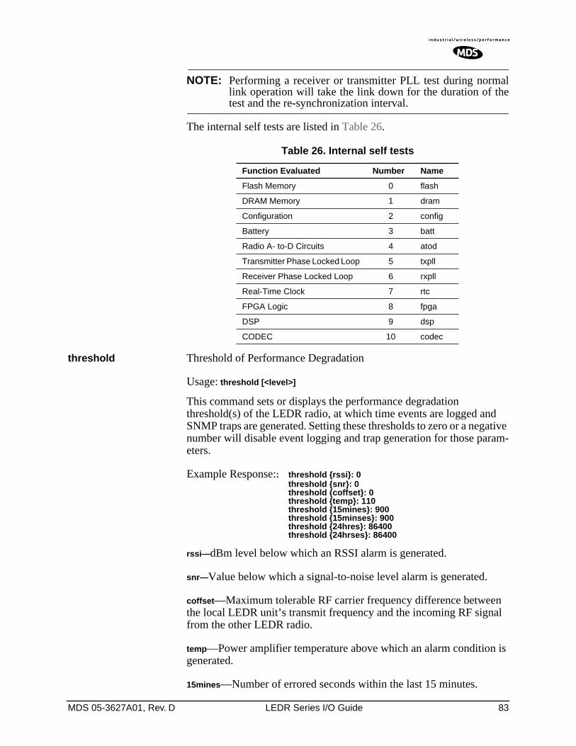
MDS 05-3627A01, Rev. D LEDR Series I/O Guide 83
NOTE: Performing a receiver or transmitter PLL test during normallink operation will take the link down for the duration of thetest and the re-synchronization interval.
The internal self tests are listed in Table 26.
threshold Threshold of Performance Degradation
Usage: threshold [<level>]
This command sets or displays the performance degradation threshold(s) of the LEDR radio, at which time events are logged and SNMP traps are generated. Setting these thresholds to zero or a negative number will disable event logging and trap generation for those param-eters.
Example Response:: threshold rssi: 0threshold snr: 0threshold coffset: 0threshold temp: 110threshold 15mines: 900threshold 15minses: 900threshold 24hres: 86400threshold 24hrses: 86400
rssi—dBm level below which an RSSI alarm is generated.
snr—Value below which a signal-to-noise level alarm is generated.
coffset—Maximum tolerable RF carrier frequency difference between the local LEDR unit’s transmit frequency and the incoming RF signal from the other LEDR radio.
temp—Power amplifier temperature above which an alarm condition is generated.
15mines—Number of errored seconds within the last 15 minutes.
Table 26. Internal self tests
Function Evaluated Number Name
Flash Memory 0 flash
DRAM Memory 1 dram
Configuration 2 config
Battery 3 batt
Radio A- to-D Circuits 4 atod
Transmitter Phase Locked Loop 5 txpll
Receiver Phase Locked Loop 6 rxpll
Real-Time Clock 7 rtc
FPGA Logic 8 fpga
DSP 9 dsp
CODEC 10 codec
84 LEDR Series I/O Guide MDS 05-3627A01, Rev. D
15minses—Number of severely errored seconds within the last 15 min-utes.
24hres—Number of errored seconds within the last 24 hours.
24hrses—Number of severely errored seconds within the last 24 hours.
time Time of Internal Clock
Usage: time [HH:MM[:SS]
This command displays or sets the time of the radio’s internal real-time clock. The radio’s real time clock operates from an internal lithium bat-tery so it is running even if the radio has no DC power connected.
The real time clock is fully compliant with Year 2000 standards.
timeslot Time Slot Assignment
Select which timeslots to transmit. This command has two uses; in Usage 1, the timeslots can be set or displayed. In Usage 2, all pending timeslots are committed/made active.
The timeslots may be different at each end of the link. They will be monotonically mapped; that is, Slot 1 is mapped to Slot 13, Slot 2 is mapped to Slot 14, etc. To select timeslots 1 through 12, enter the com-mand timeslot 1-12.
Usage 1: timeslot [-d] [slotlist]
Usage 2: timeslot -c
Variables:
–d Disable timeslot(s)–c Commit pending timeslots
Modifications to the timeslot list are kept pending until all available slots have been assigned. The user can choose to commit slots when the last available slot is added to the pending list, or by using the -c option. (See Usage 2.)
The default action is to enable given timeslots. If no arguments are entered, the currently active timeslots and pending timeslots are dis-played.
If rearrangement of timeslots is desired, some simple rules must be fol-lowed when CAS framing is used. Refer to the chart below for this dis-cussion, where “TS” = “Timeslot”:
TS00 TS01–TS15 TS16 TS17–TS31
1 M 1 N
FE1
FT1
MDS 05-3627A01, Rev. D LEDR Series I/O Guide 85
If the timeslots are rearranged such that M is to the “left” of timeslot 16, and N to the “right,” then the timeslot numbers at the other end of the link must agree (M and N). They may be re-positioned within their part of the E1 frame (to the left or right of TS16) but may not be moved to the other side.
The slotlist variable is a list of timeslots and can be a single slot number, comma separated list of slot numbers, or a range of slot numbers (i.e., 2-8). Timeslots can be entered in any order and are automatically con-figured. Extra slots will be ignored. Unassigned timeslots in the pending list are signified by MA (must assign).
NOTE: Enough slots for the full data capacity of the modem settingmust be specified or the link will not synchronize.
NOTE: FT1 timeslots are 1–24. E1 timeslots are 0–31.
NOTE: In FE1 mode timeslot 0 is always selected. When frame struc-tures are selected that contain CAS (fstruct 4-7) timeslot 16must be selected.
trapfilter Trap Filtering for SNMP
Usage: trapfilter [<critical|major|minor|inform>]
This command sets or displays which events cause SNMP traps. Fil-tering traps is done by category. Traps that are filtered are allowed to pass through the network-management system. (See trapmgr on Page 85 and snmpcomm on Page 81 for additional information.)
trapmgr Trap Manager IP Addresses
Usage: trapmgr [<1-5>] [<IP address>]
This command sets or displays the trap manager IP addresses. These are the IP addresses of up to five network-management stations on which SNMP manager software is operating, and to which notifications of SNMP events (traps) are to be sent. The IP mask used for sending traps is that set by the ip command. (See “ip” on Page 63.)
Example Response:: trapmgr: 1 = 10.2.129.22trapmgr: 2 = 0.0.0.0trapmgr: 3 = 0.0.0.0trapmgr: 4 = 0.0.0.0trapmgr: 5 = 10.2.129.1
trend Trend of RF Performance Indicators
Usage: trend [<rssi|temp|rfout|snr|fec|ifec|time|all>] [<display time (msec)>]
86 LEDR Series I/O Guide MDS 05-3627A01, Rev. D
This command is used to display continuously updated readings of: RSSI, radio temperature, RF output, signal-to-noise ratio, and FEC errors (corrected and uncorrectable). The display can be stopped by pressing Control-C on the terminal.
If the trend command is used by itself or with all (trend all), all associated parameters will be reported. More than one argument can be used to dis-play several selected items in the desired order.
NOTE: This command is not available from a Telnet session.
txkey Radio Transmitter Keying Status
Usage: txkey [on|off]
This command sets or displays the radio transmitter status. ON indicates the radio transmitter is keyed and transmitting. OFF indicates the trans-mitter is not keyed.
unitid Unit Identification Number for Orderwire and NMS
Usage: unitid [<ID>]
This command sets or displays the radio’s unit identification number. This number is used for Orderwire signaling and by the NMS (Network Management System). (See “USING ORDERWIRE” on Page 99.) The factory default is the last three numbers of the unit serial number. (1-999)
uptime Up Time
Usage: uptime
This command displays how long the radio has been powered-on.
user User Account Information
Usage: user [subcommand] [<argument>]Subcommands: add <user> <pass> <perm>
del <user>perm <user> <perm>pass
This command provides administrator access for setting new user accounts and permission levels.
NOTE: The password (pass) and user names are case sensitive andmay not exceed eight characters. Two quotation mark charac-ters ("") may be used as a “blank” password. If quotationmarks are used, the shift key or cap lock keys must bedepressed.
MDS 05-3627A01, Rev. D LEDR Series I/O Guide 87
User permission (perm) may be set to: read (r), write (w), network (n) or administrator (a). The privileges granted by each level are as follows:
• Read (r) is the lowest level of user access and allows radio informa-tion to be viewed only. Changes to radio settings are not allowed.
• Write (w) allows most, but not all radio settings to be changed.
• Network (n) allows everything permitted by lower levels, and also allows changes to the radio’s IP configuration.
• Administrator (a) allows everything permitted in lower levels, and also allows changes to be made to user accounts (add, delete, mod-ify). It is normally used by a System Administrator or other person responsible for the radio system.
Example entry: user add fieldserv secret w
The above example shows the command string for adding a new user (fieldserv), with “write” permission and a password of secret.
Example Response: user: Command Complete
NOTE: If you are logging in for the first time since the radio wasshipped from the factory, refer to Page 26 for important logininformation.
ver Version of Firmware/Hardware
Usage: ver [frw|hdw|ext]
This command displays radio version information for firmware (frw), hardware (hdw) and Extended Version Information (ext).
Example 1: LEDR> ver frw
Response 1: ver: LEDR Part #06-3451A01ver: 2.4.3 (Version of firmware P/N above)
Example 2: LEDR> ver hdw
Response 2: ver: Hardware version: A
Example 3: LEDR> ver ext
Response 3:ver: Part #06-3451A01ver: 2.4.3ver:ver: Image 1ver: Region Expected Upgradever: Firmware 2.4.3ver: DSP 1.1.0ver: FPGA Ver1.22
88 LEDR Series I/O Guide MDS 05-3627A01, Rev. D
ver: Scripts Ver1.44 ver: Option Ver1.56ver:ver: Image 2 (Active)ver: Region Expected Upgradever: Firmware 2.4.3ver: DSP 1.1.0ver: FPGA Ver1.22ver: Scripts Ver1.44ver: Option Ver1.56ver Active code: compiled Aug 15 2000 08:47:46
Note: Blank lines following “Ver:” are spaces used as vertical separations between data groups.
volume Volume of Orderwire Earpiece
Usage: volume [<level (0–255)>]
This command sets or displays the orderwire handset volume.
Example Response:: volume: 100
vox Voice Operated Transmit
Usage: vox threshold <1–100>
The vox command sets or displays the level/threshold at which the order-wire microphone will key the transmitter.
NOTE: When the orderwire microphone is spoken into, the audio willbe heard by all LEDR radios in the network which currentlyhave a handset plugged into the front panel handset jack. Onlyone station can transmit at a time; the circuit is half-duplex.
Example Response:: vox: 5
who Identifies who is currently logged on to the Network Management Ports
Usage: who
This command displays users currently logged in to the radio operating system.
6.5 Disabling the Front Panel Alarm LED for Unused E1 Option Ports
To disable the ALARM LED on the front panel for a particular E1 port, use the commands found in Table 27 below according to the E1 port number. When alarm events are pending, the alarm condition for the unused E1 ports remains until a valid input signal (as defined by G.703) is applied.
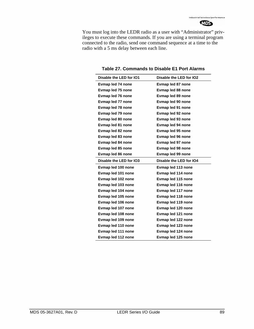
MDS 05-3627A01, Rev. D LEDR Series I/O Guide 89
You must log into the LEDR radio as a user with “Administrator” priv-ileges to execute these commands. If you are using a terminal program connected to the radio, send one command sequence at a time to the radio with a 5 ms delay between each line.
Table 27. Commands to Disable E1 Port Alarms
Disable the LED for IO1 Disable the LED for IO2
Evmap led 74 none
Evmap led 75 none
Evmap led 76 none
Evmap led 77 none
Evmap led 78 none
Evmap led 79 none
Evmap led 80 none
Evmap led 81 none
Evmap led 82 none
Evmap led 83 none
Evmap led 84 none
Evmap led 85 none
Evmap led 86 none
Evmap led 87 none
Evmap led 88 none
Evmap led 89 none
Evmap led 90 none
Evmap led 91 none
Evmap led 92 none
Evmap led 93 none
Evmap led 94 none
Evmap led 95 none
Evmap led 96 none
Evmap led 97 none
Evmap led 98 none
Evmap led 99 none
Disable the LED for IO3 Disable the LED for IO4
Evmap led 100 none
Evmap led 101 none
Evmap led 102 none
Evmap led 103 none
Evmap led 104 none
Evmap led 105 none
Evmap led 106 none
Evmap led 107 none
Evmap led 108 none
Evmap led 109 none
Evmap led 110 none
Evmap led 111 none
Evmap led 112 none
Evmap led 113 none
Evmap led 114 none
Evmap led 115 none
Evmap led 116 none
Evmap led 117 none
Evmap led 118 none
Evmap led 119 none
Evmap led 120 none
Evmap led 121 none
Evmap led 122 none
Evmap led 123 none
Evmap led 124 none
Evmap led 125 none
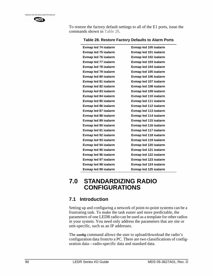
90 LEDR Series I/O Guide MDS 05-3627A01, Rev. D
To restore the factory default settings to all of the E1 ports, issue the commands shown in Table 28.
7.0 STANDARDIZING RADIO CONFIGURATIONS
7.1 Introduction
Setting up and configuring a network of point-to-point systems can be a frustrating task. To make the task easier and more predictable, the parameters of one LEDR radio can be used as a template for other radios in your system. You need only address the parameters that are site or unit-specific, such as an IP addresses.
The config command allows the user to upload/download the radio’s configuration data from/to a PC. There are two classifications of config-uration data—radio-specific data and standard data.
Table 28. Restore Factory Defaults to Alarm Ports
Evmap led 74 ioalarm
Evmap led 75 ioalarm
Evmap led 76 ioalarm
Evmap led 77 ioalarm
Evmap led 78 ioalarm
Evmap led 79 ioalarm
Evmap led 80 ioalarm
Evmap led 81 ioalarm
Evmap led 82 ioalarm
Evmap led 83 ioalarm
Evmap led 84 ioalarm
Evmap led 85 ioalarm
Evmap led 86 ioalarm
Evmap led 87 ioalarm
Evmap led 88 ioalarm
Evmap led 89 ioalarm
Evmap led 90 ioalarm
Evmap led 91 ioalarm
Evmap led 92 ioalarm
Evmap led 93 ioalarm
Evmap led 94 ioalarm
Evmap led 95 ioalarm
Evmap led 96 ioalarm
Evmap led 97 ioalarm
Evmap led 98 ioalarm
Evmap led 99 ioalarm
Evmap led 100 ioalarm
Evmap led 101 ioalarm
Evmap led 102 ioalarm
Evmap led 103 ioalarm
Evmap led 104 ioalarm
Evmap led 105 ioalarm
Evmap led 106 ioalarm
Evmap led 107 ioalarm
Evmap led 108 ioalarm
Evmap led 109 ioalarm
Evmap led 110 ioalarm
Evmap led 111 ioalarm
Evmap led 112 ioalarm
Evmap led 113 ioalarm
Evmap led 114 ioalarm
Evmap led 115 ioalarm
Evmap led 116 ioalarm
Evmap led 117 ioalarm
Evmap led 118 ioalarm
Evmap led 119 ioalarm
Evmap led 120 ioalarm
Evmap led 121 ioalarm
Evmap led 122 ioalarm
Evmap led 123 ioalarm
Evmap led 124 ioalarm
Evmap led 125 ioalarm
MDS 05-3627A01, Rev. D LEDR Series I/O Guide 91
Radio-Specific data is:
• Frequencies • Target Power• Thresholds• Calibration Data• IP Address• IP Routing Table• Network Settings
Standard radio data are the configuration parameters that are common in all LEDR radios.
Both types of data can be uploaded and downloaded between the radio and a PC. It is up to the user to decide whether to download both types or just the standard (core) data. Once the data is on a PC, the file can be edited off-line, for example, the configuration data, if desired. The cus-tomized configuration file can then be downloaded to other LEDR radios in your system from your PC.
7.2 Setup by TFTP
To use this function the user will need:
• A PC with a TFTP server running.• The IP address of the PC running the TFTP server.
Finding IP Addresses
To determine the IP address of a Windows NT/2000/XP computer, select Run from the Start menu, and enter cmd. At the cmd prompt, type ipconfig. (For Windows 95/98 platforms, select Run from the Start menu and enter winipcfg.) The IP address of the radio can be determined using the radio’s ip command.
Downloading Procedure
To download the configuration data from the LEDR radio to a file (filename.txt) on the user’s PC, enter the following command:
LEDR> config send [filename.txt] [1.2.3.4 <IP Address>]
The file, filename.txt, will be written to in the default path set in the TFTP server. The numeric string, “1.2.3.4”, is the IP address of the PC destined to receive the file.
Uploading Procedure
To upload into a LEDR radio only the standard configuration data from a file on the PC (filename.txt) to the radio enter the following command:
LEDR> config get [filename.txt] [1.2.3.4 <IP Address>]
92 LEDR Series I/O Guide MDS 05-3627A01, Rev. D
To download both the standard and radio-specific configuration data from a file on the PC (filename.txt) to the radio enter the following com-mand:
LEDR> config getall [filename.txt] [1.2.3.4 <IP Address>]
Ideally, the process of updating a system would go like this:
1. Upload the current configuration data from each radio to a specific file on your PC.
At radio 1 CONSOLE Port enter: config send radio_1.txt 1.2.3.4At radio 2 CONSOLE Port enter: config send radio_2.txt 1.2.3.4 (etc.)
2. Upgrade the software on each radio.
3. Boot from the new software.
4. Download the saved configuration data from Step 1 back into each radio using the getall subcommand so that you will get both the stan-dard and radio-specific parameters.
At radio 1 CONSOLE Port enter: config getall radio_1.txt 1.2.3.4
At radio 2 CONSOLE Port enter: config getall radio_2.txt 1.2.3.4 (etc.)
7.3 Setup Through the DB-9 CONSOLE Port
You have the option of sending the configuration data to the CONSOLE Port instead of sending it to a file on a PC. Then the terminal program can be set to log the data as it is created by the radio. The advantage of this option is that you do not need to use the TFTP server, routing, etc. on the PC.
During the upload, the LEDR software will prompt you to begin/end recording at the terminal program. You will also be prompted on how to end a download.
When the config get downloading option is chosen (standard data only), the software will filter out all the radio-specific parameters as they come through.
To upload the data to the CONSOLE Port:
LEDR> config send console
To download only the standard data via the CONSOLE Port:
LEDR> config get console
To download standard and radio-specific data: LEDR> config getall console
MDS 05-3627A01, Rev. D LEDR Series I/O Guide 93
8.0 UPGRADING LEDR FIRMWARE
8.1 Introduction
The LEDR radio’s firmware can be upgraded with new software releases that may be issued from time-to-time by Microwave Data Sys-tems. To support firmware upgrades while the radio is in use, the LEDR radio contains two complete copies of its firmware. Once the inactive version is replaced, the radio can be rebooted using the code in the new firmware. However, if an error occurs during the download, the radio can easily recover because it always has a complete copy of firmware available.
NOTE: Any time new firmware is loaded into a radio, it must be powercycled. Merely rebooting a radio will not guarantee properoperation with the new firmware.
Firmware reprogramming can be done using one of three methods:
1. Locally through the front panel CONSOLE Port .
2. Locally using TFTP and Telnet through the ETHERNET Port .
3. Remotely over a network connection using TFTP and Telnet to the
ETHERNET Port .
The procedures that follow use one or both of two utilities found in MDS’ LEDR Utilities package. These utilities will facilitate local and remote transferring of firmware files to and from the LEDR radio. These applications are available from Microwave Data Systems on floppy disk (P/N 03-3631A01) or on the FTP section of the MDS Internet site at www.microwavedata.com.
The following sections will explain how to program new firmware into the radio using each of the three connection options. They assume the LEDR Utilities are installed on each computer system named in the pro-cedure.
NOTE: The ETHERNET, SERVICE CHANNEL and CONSOLE Portsshare a common data channel when loading firmwareover-the-air. Transferring the radio firmware image file (≈ 1MB), may take up to 30 minutes if there is other activity on anyof the other ports.
Regardless of your connection to the LEDR radio, loadingdata/firmware into the radio’s SRAM is much slower thanloading software onto a PC hard drive or RAM.
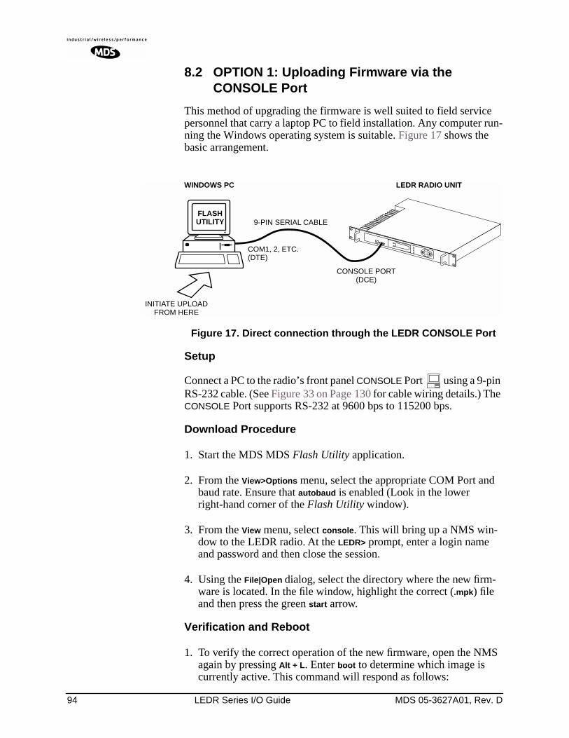
94 LEDR Series I/O Guide MDS 05-3627A01, Rev. D
8.2 OPTION 1: Uploading Firmware via the CONSOLE Port
This method of upgrading the firmware is well suited to field service personnel that carry a laptop PC to field installation. Any computer run-ning the Windows operating system is suitable. Figure 17 shows the basic arrangement.
Invisible place holder
Figure 17. Direct connection through the LEDR CONSOLE Port
Setup
Connect a PC to the radio’s front panel CONSOLE Port using a 9-pin RS-232 cable. (See Figure 33 on Page 130 for cable wiring details.) The CONSOLE Port supports RS-232 at 9600 bps to 115200 bps.
Download Procedure
1. Start the MDS MDS Flash Utility application.
2. From the View>Options menu, select the appropriate COM Port and baud rate. Ensure that autobaud is enabled (Look in the lower right-hand corner of the Flash Utility window).
3. From the View menu, select console. This will bring up a NMS win-dow to the LEDR radio. At the LEDR> prompt, enter a login name and password and then close the session.
4. Using the File|Open dialog, select the directory where the new firm-ware is located. In the file window, highlight the correct (.mpk) file and then press the green start arrow.
Verification and Reboot
1. To verify the correct operation of the new firmware, open the NMS again by pressing Alt + L. Enter boot to determine which image is currently active. This command will respond as follows:
FLASHUTILITY
COM1, 2, ETC.(DTE)
9-PIN SERIAL CABLE
CONSOLE PORT(DCE)
INITIATE UPLOADFROM HERE
LEDR RADIO UNITWINDOWS PC
MDS 05-3627A01, Rev. D LEDR Series I/O Guide 95
boot: Image 1 is Active or, boot: Image 2 is Active
2. The new firmware is downloaded into the inactive image. Therefore, if the radio responded Image 1 is Active, enter “image verify” com-mand, iverify 2, otherwise, enter iverify 1. The radio will respond indi-cating whether or not the image has been verified as being a valid file, it will not determine if the contents are complementary to the other firmware image. If the image does not verify, try downloading the firmware again into the radio.
NOTE: The following paragraph describes rebooting the radio. Thisaction will disrupt the communications link.
3. Once the image has been verified, the radio must be rebooted using the new firmware. This is done by entering the command boot 1 or boot 2, where the 1 or 2 corresponds with the image number used with the iverify command above.
4. Once the radio has rebooted and Flash Utility screen displays the LEDR> prompt, the firmware can be downloaded or copied into the other image. Often, copying the firmware from one image to the other can be faster than performing a second download. To copy the firmware over to the other image, simply enter icopy. The radio will prompt you for confirmation (y/n) and then begin copying.
8.3 OPTION 2: Uploading Firmware Locally by Telnet via Ethernet
This method can be used in the field or in a workshop by using a Win-dows computer equipped with an Ethernet interface. Figure 17 shows the basic arrangement.
NOTE: You must know the IP address of the LEDR Radio and the PCthat you are going to connect together. (Both units must havethe same Subnet, Netmask and Gateway addresses, or at leasthave routes to one another.) This is essential for a directEthernet connection.
To find the IP address of your Windows computer, refer toFinding IP Addresses on Page 91. The IP address of the radiocan be determined using the radio’s ip command.
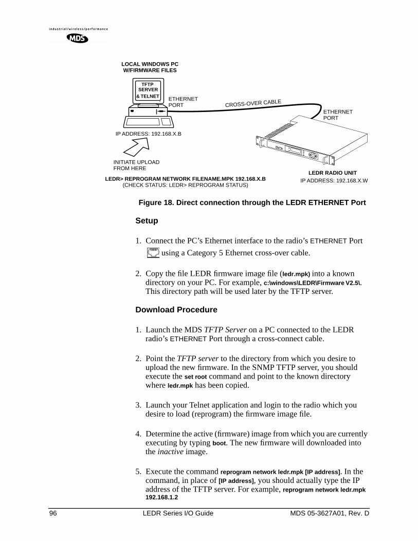
96 LEDR Series I/O Guide MDS 05-3627A01, Rev. D
Invisible place holder
Figure 18. Direct connection through the LEDR ETHERNET Port
Setup
1. Connect the PC’s Ethernet interface to the radio’s ETHERNET Port
using a Category 5 Ethernet cross-over cable.
2. Copy the file LEDR firmware image file (ledr.mpk) into a known directory on your PC. For example, c:\windows\LEDR\Firmware V2.5\. This directory path will be used later by the TFTP server.
Download Procedure
1. Launch the MDS TFTP Server on a PC connected to the LEDR radio’s ETHERNET Port through a cross-connect cable.
2. Point the TFTP server to the directory from which you desire to upload the new firmware. In the SNMP TFTP server, you should execute the set root command and point to the known directory where ledr.mpk has been copied.
3. Launch your Telnet application and login to the radio which you desire to load (reprogram) the firmware image file.
4. Determine the active (firmware) image from which you are currently executing by typing boot. The new firmware will downloaded into the inactive image.
5. Execute the command reprogram network ledr.mpk [IP address]. In the command, in place of [IP address], you should actually type the IP address of the TFTP server. For example, reprogram network ledr.mpk 192.168.1.2
& TELNET ETHERNETPORT
INITIATE UPLOADFROM HERE
LEDR RADIO UNIT
LOCAL WINDOWS PCW/FIRMWARE FILES
ETHERNETPORT
LEDR> REPROGRAM NETWORK FILENAME.MPK 192.168.X.B(CHECK STATUS: LEDR> REPROGRAM STATUS)
IP ADDRESS: 192.168.X.B
CROSS-OVER CABLE
IP ADDRESS: 192.168.X.W
TFTPSERVER
MDS 05-3627A01, Rev. D LEDR Series I/O Guide 97
6. If desired, the status of the transfer during reprogramming may be displayed by typing reprogram status.
7. The TFTP Server and radio will notify you when the programming is complete.
Verification and Reboot
1. To verify the integrity of the new firmware enter boot to determine which image is currently active. This command will respond as follows:
boot: Image 1 is Active or, boot: Image 2 is Active
If the radio responded to the boot command with Image 1 is Active, enter the “image verify” command, iverify 2, otherwise, enter iverify 1. The radio will respond indicating whether or not the image has been verified as being a valid file, it will not determine if the contents are complementary to the other firmware image. If the image does not verify, try downloading the firmware again into the radio.
NOTE: The following paragraph describes rebooting the radio. Thisaction will disrupt the communications link.
2. Once the image has been verified, the radio must be rebooted using the new firmware. This is done by entering the command boot 1 or boot 2, where the 1 or 2 corresponds with the image number used with the iverify command above.
3. Once the radio has rebooted and Flash Utility screen displays the LEDR> prompt, the firmware can be downloaded or copied into the other image. Often, copying the firmware from one image to the other can be faster than performing a second download. To copy the firmware over to the other image, simply enter icopy. The radio will prompt you for confirmation (y/n) and then begin copying.
8.4 OPTION 3: Uploading Firmware from a Remote Server via Ethernet
Setup
Connect the LEDR radio’s ETHERNET connector to network which has a PC connected with the desired LEDR firmware on its hard drive. The “network” can be a local area network, a wide-area network or any IP network that can connect the two units.
The computer hosting the firmware image, must be running a TFTP server software. If not, install, launch and configure the MDS TFTP Server software found on the LEDR Utilities disk. The setup configura-tion is shown in Figure 19.
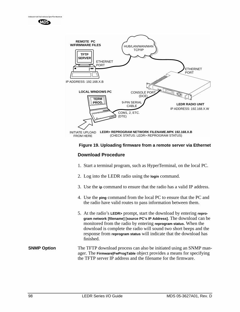
98 LEDR Series I/O Guide MDS 05-3627A01, Rev. D
Invisible place holder
Figure 19. Uploading firmware from a remote server via Ethernet
Download Procedure
1. Start a terminal program, such as HyperTerminal, on the local PC.
2. Log into the LEDR radio using the login command.
3. Use the ip command to ensure that the radio has a valid IP address.
4. Use the ping command from the local PC to ensure that the PC and the radio have valid routes to pass information between them.
5. At the radio’s LEDR> prompt, start the download by entering repro-gram network [filename] [source PC’s IP Address]. The download can be monitored from the radio by entering reprogram status. When the download is complete the radio will sound two short beeps and the response from reprogram status will indicate that the download has finished.
SNMP Option The TFTP download process can also be initiated using an SNMP man-ager. The Firmware|FwProgTable object provides a means for specifying the TFTP server IP address and the filename for the firmware.
TFTPSERVER
ETHERNETPORT
9-PIN SERIALCABLE
CONSOLE PORT(DCE)
INITIATE UPLOADFROM HERE
LEDR RADIO UNIT
REMOTE PCW/FIRMWARE FILES HUB/LAN/WAN/MAN
TCP/IP
ETHERNETPORT
COM1, 2, ETC.(DTE)
TERMPROG.
LEDR> REPROGRAM NETWORK FILENAME.MPK 192.168.X.B(CHECK STATUS: LEDR> REPROGRAM STATUS)
IP ADDRESS: 192.168.X.B
IP ADDRESS: 192.168.X.W
LOCAL WINDOWS PC
MDS 05-3627A01, Rev. D LEDR Series I/O Guide 99
Verification and Reboot
When the download is complete, verify the firmware image and reboot the radio as described under Verification and Reboot in Paragraph See “Verification and Reboot” on Page 94 for the procedure.
9.0 USING ORDERWIRE
9.1 Introduction
A handset may be plugged into the front panel of the LEDR radio to allow voice communications between radio sites (see Figure 20). This can be especially useful during setup and maintenance activities. All radios on the network can hear what is said by any individual speaking into a handset. No other radio may transmit on the orderwire until the current speaker is finished. Depending on the number of hops, the link data rates, and Interleave setting, there may be a noticeable latency from one end of the network to the other.
The front panel alert function (See “Unit ID” on Page 34) and alert com-mand (Page 51) can be used to signal all units in the network or a spe-cific radio.
Normal payload data is not affected by Orderwire use. The Orderwire uses voice-compression technology that introduces a slight, but notice-able, delay in Orderwire audio.
The orderwire will not interrupt the normal data flow through the LEDR data communication channel, however, it will reduce the throughput efficiency of any data communications on the Service Channel during periods of voice transmission.
A handset kit is available from MDS (P/N 02-1207A01), which pro-vides basic communication services but does not contain a built-in DTMF (tone) keypad. (The Orderwire supports the transmission of DTMF-type signaling by detecting tones at the source, and regenerating them at the receiving end, however, there are no DTMF supported radio functions in the LEDR radios.)
9.2 Setup
Program the vox and volume setting for each radio. The volume setting is user preference. The vox setting requires some forethought. The higher the vox setting, the louder the user must speak to get the voice decoder to recognize the speech. This will, however, prevent noise from entering the “line.” A low vox level will recognize speech better but may transmit more noise with the speech. The user should experiment with the vox setting to determine the best level for the speaker and the noise environ-ment.
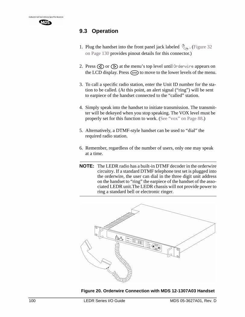
100 LEDR Series I/O Guide MDS 05-3627A01, Rev. D
9.3 Operation
1. Plug the handset into the front panel jack labeled . (Figure 32 on Page 130 provides pinout details for this connector.)
2. Press or at the menu’s top level until Orderwire appears on the LCD display. Press to move to the lower levels of the menu.
3. To call a specific radio station, enter the Unit ID number for the sta-tion to be called. (At this point, an alert signal (“ring”) will be sent to earpiece of the handset connected to the “called” station.
4. Simply speak into the handset to initiate transmission. The transmit-ter will be dekeyed when you stop speaking. The VOX level must be properly set for this function to work. (See “vox” on Page 88.)
5. Alternatively, a DTMF-style handset can be used to “dial” the required radio station.
6. Remember, regardless of the number of users, only one may speak at a time.
NOTE: The LEDR radio has a built-in DTMF decoder in the orderwirecircuitry. If a standard DTMF telephone test set is plugged intothe orderwire, the user can dial in the three digit unit addresson the handset to “ring” the earpiece of the handset of the asso-ciated LEDR unit.The LEDR chassis will not provide power toring a standard bell or electronic ringer.
Invisible place holder
Figure 20. Orderwire Connection with MDS 12-1307A03 Handset
ENTER
MDS 05-3627A01, Rev. D LEDR Series I/O Guide 101
9.4 Related NMS Commands
The orderwire can be configured by the NMS commands or through the front panel. The earpiece volume is more easily set by the front panel controls as the level is dependent on personal preference.
vox – Voice level (relative) at which speech will be detected by the soft-ware (See “vox” on Page 88)
volume – Sets/displays the handset volume (See “volume” on Page 88)
alert – Sends an orderwire alert to a specific radio or to all the radios on the network (See “alert” on Page 51)
10.0 USING THE SERVICE CHANNEL
10.1 Concept
The Service Channel sends and receives ASCII-based information at 9600 bps in a half-duplex broadcast mode throughout the network. This means that any data coming through the Service Channel Port of a radio will be broadcast to the Service Channel of each radio in the network. There can be only one radio transmitting Service Channel data over the network at a time and the data will always be sent to every radio on the network. No other radio will be allowed to transmit until the current sender is finished.
If a radio does receive data in the Service Channel Port while another radio is the active-sender, the data coming in the port will be queued and sent when the active sender is finished. Depending on the number of hops, link data rate, and Interleave setting, there may be a noticeable latency from one end of the network to the other.
10.2 Setup
The user can configure all the Service Channel parameters for a specific radio. The port may be enabled or disabled. In the disabled state (svch port off), any data that comes in the Service Channel port will be dis-carded and any Service Channel data that comes into the radio from another radio in the network will be passed along to the rest of the net-work but not sent out the Service Channel Port. When the Service Channel Port (svch port on) is enabled, it will behave based on the other settings.
The most important setting is the echo parameter. Echo is used with a terminal emulator on a PC and the program does not display on the screen character keyed in by the user.
102 LEDR Series I/O Guide MDS 05-3627A01, Rev. D
When you set up a system, you must be careful to avoid an infinite loop. If echo is enabled, then every character that enters the Service Channel port will be echoed back out the port. When echo is disabled then data that comes in the Service Channel port is not sent back out the port. Trouble may arise if the device that is connected to the Service Channel also echoes the data it sends. In that case, the device will send characters into the Service Channel Port, the radio will echo the characters back to the device, the device will consider the echoed data to be input which it will in turn echo back to the radio, etcetera, until an overflow condition occurs.
You must also set the communication parameters (baud rate, stop bits, char length, and parity) via the svch subcommands so that the settings match those at the device connected to the Service Channel Port.
Lastly, the user can re-initialize the Service Channel port via the svch reset command. This may be helpful in the case where an infinite loop overflow condition has locked the port.
10.3 Usage
The Service Channel supports ASCII data transfer over the network in broadcast fashion. As a result, devices connected to the Service Channel Ports of different radios will appear to have a transparent half-duplex connection between them.
10.4 NMS Commands
This command is used to set/display Service Channel parameters.
Usage: svch [subcommand] [<argument>]
Subcommands: baudcharechooffoffonparityresetstop
on—Enable the Service Channel
off—Disable the Service Channel
reset—Re-initialize the Service Channel
echo—on/off
baud—300, 600, 1200, 2400, 4800 and 9600
char— 5, 6, 7, 8 (ASCII character length in bits)
parity—none, even, odd
stop—1, 2 (Stop bits)
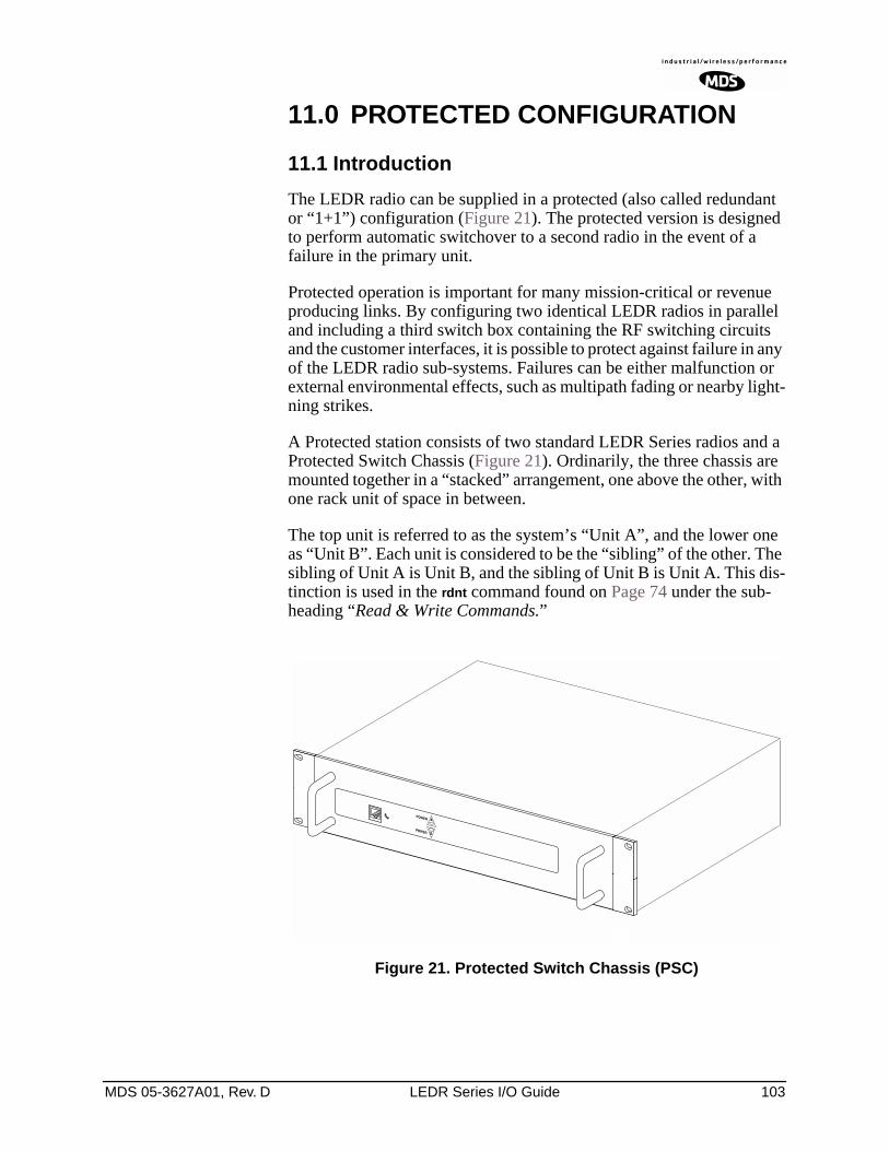
MDS 05-3627A01, Rev. D LEDR Series I/O Guide 103
11.0 PROTECTED CONFIGURATION
11.1 Introduction
The LEDR radio can be supplied in a protected (also called redundant or “1+1”) configuration (Figure 21). The protected version is designed to perform automatic switchover to a second radio in the event of a failure in the primary unit.
Protected operation is important for many mission-critical or revenue producing links. By configuring two identical LEDR radios in parallel and including a third switch box containing the RF switching circuits and the customer interfaces, it is possible to protect against failure in any of the LEDR radio sub-systems. Failures can be either malfunction or external environmental effects, such as multipath fading or nearby light-ning strikes.
A Protected station consists of two standard LEDR Series radios and a Protected Switch Chassis (Figure 21). Ordinarily, the three chassis are mounted together in a “stacked” arrangement, one above the other, with one rack unit of space in between.
The top unit is referred to as the system’s “Unit A”, and the lower one as “Unit B”. Each unit is considered to be the “sibling” of the other. The sibling of Unit A is Unit B, and the sibling of Unit B is Unit A. This dis-tinction is used in the rdnt command found on Page 74 under the sub-heading “Read & Write Commands.”
Invisible place holder
Figure 21. Protected Switch Chassis (PSC)
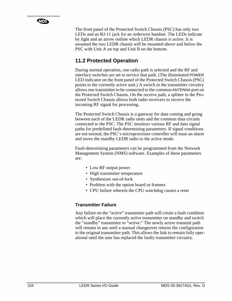
104 LEDR Series I/O Guide MDS 05-3627A01, Rev. D
The front panel of the Protected Switch Chassis (PSC) has only two LEDs and an RJ-11 jack for an orderwire handset. The LEDs indicate by light and an arrow outline which LEDR chassis is active. It is assumed the two LEDR chassis will be mounted above and below the PSC with Unit A on top and Unit B on the bottom.
11.2 Protected Operation
During normal operation, one radio path is selected and the RF and interface switches are set to service that path. (The illuminated POWER LED indicator on the front panel of the Protected Switch Chassis (PSC) points to the currently active unit.) A switch in the transmitter circuitry allows one transmitter to be connected to the common ANTENNA port on the Protected Switch Chassis. On the receive path, a splitter in the Pro-tected Switch Chassis allows both radio receivers to receive the incoming RF signal for processing.
The Protected Switch Chassis is a gateway for data coming and going between each of the LEDR radio units and the common data circuits connected to the PSC. The PSC monitors various RF and data signal paths for predefined fault-determining parameters. If signal conditions are not normal, the PSC’s microprocessor controller will issue an alarm and move the standby LEDR radio to the active mode.
Fault-determining parameters can be programmed from the Network Management System (NMS) software. Examples of these parameters are:
• Low RF output power• High transmitter temperature• Synthesizer out-of-lock• Problem with the option board or framers• CPU failure wherein the CPU watchdog causes a reset
Transmitter Failure
Any failure on the “active” transmitter path will create a fault condition which will place the currently active transmitter on standby and switch the “standby” transmitter to “active.” The newly active transmit path will remain in use until a manual changeover returns the configuration to the original transmitter path. This allows the link to remain fully oper-ational until the user has replaced the faulty transmitter circuitry.
MDS 05-3627A01, Rev. D LEDR Series I/O Guide 105
Receiver Failure
Both receivers are fed via an RF splitter from the antenna port. Each RF path is buffered and monitored for receive signal integrity for uncorrect-able bit-errors. If the “active” receive circuitry fails, uncorrectable bit-errors will be detected. The modem receive switch will first deter-mine that the “standby” receive path is operational (no uncorrectable bit errors) and will switch accordingly.
11.3 Configuration Options—Warm or Hot Standby
The protected LEDR radio may be configured for either warm or hot standby operation. In warm standby, the standby transmitter is powered down. This offers the advantages of significantly reduced power con-sumption, since only one transmitter path is powered. However, upon transmitter failure, the switchover takes longer due to the transmitter having to be powered up.
In a hot standby link, the standby transmitter is powered up at all times and transmits into a dummy load. Switchover to active status is less than 50 milliseconds. The hot standby mode offers the advantages of faster switchover time and increased overall system availability, but results in higher power consumption for the station.
11.4 PSC Rear Panel Connectors
The following are descriptions of the rear panel connections of the Pro-tected Switch Chassis. The PSC’s rear chassis is shown in Figure 22.
Figure 21 presents an inter-unit cabling diagram for protected configu-rations.
Figure 22. Protected Switch Chassis—Rear Panel
RF CONNECTORS
530 (A&B)
Antenna
RxA TxA
TxBRxB
530 (A&B)E1
12
34 EIA-530-A Service ChannelEthernetProtected (A+B)
A
B
External
RX TX
ETHERNETE1/T1 DATAPROTECTED DATA EIA-530-A SERVICE
CHANNEL
106 LEDR Series I/O Guide MDS 05-3627A01, Rev. D
RxA
The RXA (Receive—Radio A) connector is a N-type coaxial connector. It connects to the RX port on the rear panel of Radio A via a short coaxial cable.
RxB
Same as RXA, but for Radio B.
Antenna
The ANTENNA connector is a N-type coaxial connector. It serves as the connection point for the station antenna.
TxA
The TXA (transmit, radio A) connector is a N-type coaxial connector. It connects to the TX port on the rear panel of Radio A via a short coaxial cable.
TxB
Same as TXA, but for Radio B.
Protected (Data)
This pair of connectors accepts data signals from each of the LEDR radios. The top connector is for Radio A, and the bottom connector is for Radio B. For pinout information, please consult the factory. Replace-ment cables are available from MDS (P/N 03-3837A02).
E1
This is a block of four RJ-45 modular connectors for connection to a multiplexer or other customer-supplied E1 equipment. For detailed pin information, Figure 34 on Page 130.
These connectors are not operational on “S” Series (Subrate) radios.
Ethernet
The ETHERNET connector provides access to the embedded SNMP agent and other elements of the TCP/IP network management system. The connector is a standard 10 Base-T connection with an RJ-45 mod-ular connector. For detailed pin information, see Figure 34 on Page 130.
530 (A&B)
This pair of DB-25 connectors accepts EIA-530 data signals from each of the LEDR radios. The top connector is for Radio A, and the bottom connector is for Radio B. For pinout information, see Figure 36 on Page 131.
MDS 05-3627A01, Rev. D LEDR Series I/O Guide 107
EIA-530-A
This DB-25 connector provides a connection point for customer-sup-plied EIA-530 data equipment. Note: This port is not operational in full-rate models.
Service Channel
In a protected configuration, this DB-9 connector becomes the Service Channel connection for both LEDR radios. (In the protected radio con-figuration, the Service Channel connectors on the radios are non-func-tional.) For detailed pin information, see “Service Channel—Rear Panel” on Page 131.
11.5 Inter-Unit Cabling for Protected Stations
The required cabling between the two radios and the Protected Switch Chassis is dependent on the data interface, unit type (subrate versus full-rate), and transmit and receive antenna configuration.
The cabling for a pair of standard radios with internal duplexers is shown in Figure 23.
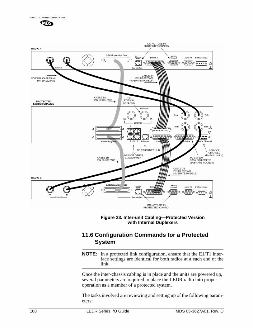
108 LEDR Series I/O Guide MDS 05-3627A01, Rev. D
Figure 23. Inter-unit Cabling—Protected Version with Internal Duplexers
11.6 Configuration Commands for a Protected System
NOTE: In a protected link configuration, ensure that the E1/T1 inter-face settings are identical for both radios at a each end of thelink.
Once the inter-chassis cabling is in place and the units are powered up, several parameters are required to place the LEDR radio into proper operation as a member of a protected system.
The tasks involved are reviewing and setting up of the following param-eters:
DO NOT USE INPROTECTED CONFIG.
TXExternal Data Interface
EIA-530-AEthernetNMS
ServiceChannel Alarm I/O DC Power Input
EIA-530-AEthernetNMS
Data Interface
ServiceChannel Alarm I/O DC Power Input
TO ETHERNET HUB SERVICECHANNEL
(For both radios)
RX
TXExternal
RX
G.703/Expansion Data
G.703/Expansion Data
RADIO A
RADIO B
PROTECTEDSWITCH CHASSIS
DO NOT USE INPROTECTED CONFIG.
CABLE 2AP/N 03-3828A01
(SUBRATE MODELS)
TOSTATIONANTENNA
TOMUX OR OTHERE1 EQUIPMENT TO EIA-530
DATA EQUIPMENT(SUBRATE MODELS)
CABLE 1AP/N 03-3837A02
CABLE 1BP/N 03-3837A02
CABLE 2BP/N 03-3828A01(SUBRATE MODELS)
Antenna
TxA
TxBRxB
530 (A&B)E1
12
34 EIA-530-A Service ChannelEthernetProtected (A+B)
A
B
External
RX TX
RxA
COAXIAL CABLES (4)P/N 19-1323A03
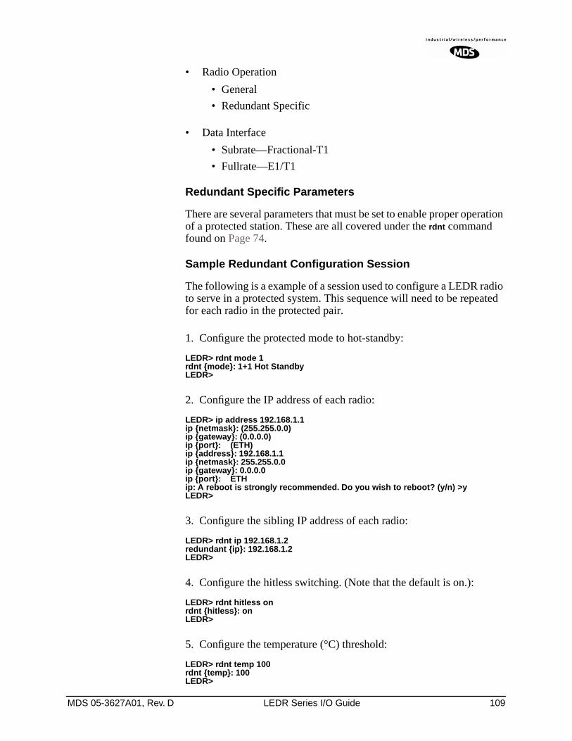
MDS 05-3627A01, Rev. D LEDR Series I/O Guide 109
• Radio Operation
• General
• Redundant Specific
• Data Interface
• Subrate—Fractional-T1
• Fullrate—E1/T1
Redundant Specific Parameters
There are several parameters that must be set to enable proper operation of a protected station. These are all covered under the rdnt command found on Page 74.
Sample Redundant Configuration Session
The following is a example of a session used to configure a LEDR radio to serve in a protected system. This sequence will need to be repeated for each radio in the protected pair.
1. Configure the protected mode to hot-standby:
LEDR> rdnt mode 1rdnt mode: 1+1 Hot StandbyLEDR>
2. Configure the IP address of each radio:
LEDR> ip address 192.168.1.1ip netmask: (255.255.0.0)ip gateway: (0.0.0.0)ip port: (ETH)ip address: 192.168.1.1ip netmask: 255.255.0.0ip gateway: 0.0.0.0ip port: ETHip: A reboot is strongly recommended. Do you wish to reboot? (y/n) >yLEDR>
3. Configure the sibling IP address of each radio:
LEDR> rdnt ip 192.168.1.2redundant ip: 192.168.1.2LEDR>
4. Configure the hitless switching. (Note that the default is on.):
LEDR> rdnt hitless onrdnt hitless: onLEDR>
5. Configure the temperature (°C) threshold:
LEDR> rdnt temp 100rdnt temp: 100LEDR>
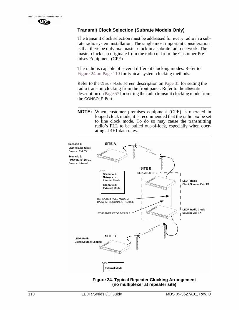
110 LEDR Series I/O Guide MDS 05-3627A01, Rev. D
Transmit Clock Selection (Subrate Models Only)
The transmit clock selection must be addressed for every radio in a sub-rate radio system installation. The single most important consideration is that there be only one master clock in a subrate radio network. The master clock can originate from the radio or from the Customer Pre-mises Equipment (CPE).
The radio is capable of several different clocking modes. Refer to Figure 24 on Page 110 for typical system clocking methods.
Refer to the Clock Mode screen description on Page 35 for setting the radio transmit clocking from the front panel. Refer to the clkmode description on Page 57 for setting the radio transmit clocking mode from the CONSOLE Port.
NOTE: When customer premises equipment (CPE) is operated inlooped clock mode, it is recommended that the radio not be setto line clock mode. To do so may cause the transmittingradio’s PLL to be pulled out-of-lock, especially when oper-ating at 4E1 data rates.
Invisible place holder
Figure 24. Typical Repeater Clocking Arrangement(no multiplexer at repeater site)
CPE
REPEATER NULL-MODEMDATA INTERCONNECT CABLE
ETHERNET CROSS-CABLE
REPEATER SITECPE
SITE A
SITE B
SITE C
LEDR RadioClock Source: Ext. TX
LEDR Radio ClockSource: Ext. TX
LEDR RadioClock Source: Looped
Network orInternal Clock
External Mode
Scenario 1:
LEDR Radio ClockSource: Internal
Scenario 2:
Scenario 1:
Scenario 2:External Mode
LEDR Radio ClockSource: Ext. TX
MDS 05-3627A01, Rev. D LEDR Series I/O Guide 111
12.0 SPACE DIVERSITY OPERATION
12.1 Introduction
Space diversity operation is an effective mechanism of increasing a radio link’s resilience to transmission impairments such as multipath fading or frequency selective fading. In difficult transmission environ-ments such as over highly reflective and moving water paths, or in arid environments where atmospheric ducting occurs, space diversity is the most effective way of maintaining a continuous radio link.
In a space diversity link, two radio receivers are operated in parallel, from two separate antennas mounted several wavelengths apart verti-cally on the antenna tower. The separation of antennas is such that when one antenna experiences fading due to multi-path interference, the other antenna, being several wavelengths away, is not likely to experience the same fade. Thus, one receive path may experience uncorrectable errors, while the other path will be error free. Similar to the protected operation, the receive modem switch will determine which buffered data path is operating with the highest integrity, and select that path without inducing any additional bit errors into the link.
Space diversity is especially effective in changeable multi-path environ-ments such as over tidal water paths. Since water is highly reflective, there will be continual “constructive” and “destructive” interference at each single antenna over the course of the day as the water rises and falls and the reflected water path interferes with the line-of-sight path. By correct vertical positioning of the antennas, these effects can be negated, allowing one antenna to see a good signal while the other is experi-encing fading, and the modem switching accordingly to allow the link to operate error- free.
The space diversity LEDR radio is available only in a hot standby con-figuration.
12.2 User Interface & Control
Protected operation is configured using the Redundant screen (Page 41) on either radio front panel, or with the rdnt command from a NMS ter-minal (see Page 74).
12.3 Transmit Clock Selection
There is no difference between a space diversity system and redundant radio arrangements with respect to transmit clock selection. Fullrate radios require no user intervention for clocking. Users of subrate sys-tems should set the radio clocks as described for subrate systems. See “Transmit Clock Selection” on Page 111 for further information.
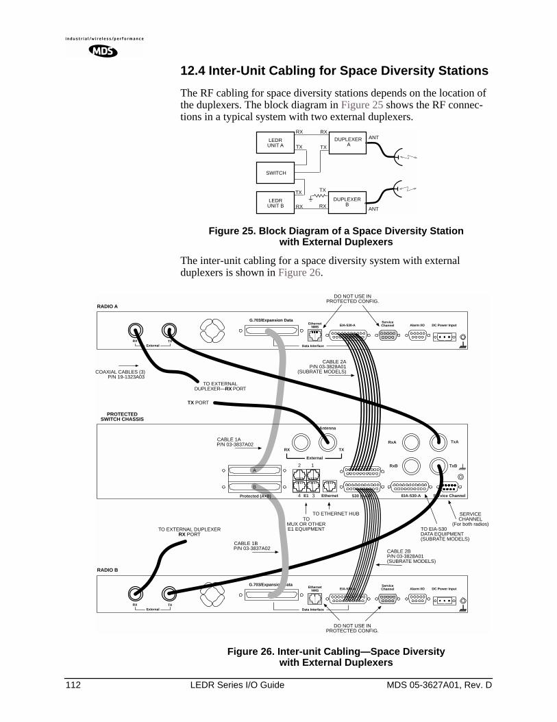
112 LEDR Series I/O Guide MDS 05-3627A01, Rev. D
12.4 Inter-Unit Cabling for Space Diversity Stations
The RF cabling for space diversity stations depends on the location of the duplexers. The block diagram in Figure 25 shows the RF connec-tions in a typical system with two external duplexers.
Figure 25. Block Diagram of a Space Diversity Stationwith External Duplexers
The inter-unit cabling for a space diversity system with external duplexers is shown in Figure 26.
Figure 26. Inter-unit Cabling—Space Diversitywith External Duplexers
RX
TX
ANT
TX
RX
DUPLEXER A
LEDRUNIT B
LEDRUNIT A
SWITCH
TX
DUPLEXERB
TX
RX RX ANT
DO NOT USE INPROTECTED CONFIG.
TXExternal Data Interface
EIA-530-AEthernetNMS
ServiceChannel Alarm I/O DC Power Input
EIA-530-AEthernetNMS
Data Interface
ServiceChannel Alarm I/O DC Power Input
TO ETHERNET HUB SERVICECHANNEL
(For both radios)
RX
TXExternal
RX
G.703/Expansion Data
G.703/Expansion Data
RADIO A
RADIO B
PROTECTEDSWITCH CHASSIS
DO NOT USE INPROTECTED CONFIG.
CABLE 2AP/N 03-3828A01
(SUBRATE MODELS)
TX PORT
TOMUX OR OTHERE1 EQUIPMENT TO EIA-530
DATA EQUIPMENT(SUBRATE MODELS)
CABLE 1AP/N 03-3837A02
CABLE 1BP/N 03-3837A02
CABLE 2BP/N 03-3828A01(SUBRATE MODELS)
Antenna
TxA
TxBRxB
530 (A&B)E1
12
34 EIA-530-A Service ChannelEthernetProtected (A+B)
A
B
External
RX TX
RxA
TO EXTERNALDUPLEXER—RX PORT
COAXIAL CABLES (3)P/N 19-1323A03
TO EXTERNAL DUPLEXERRX PORT
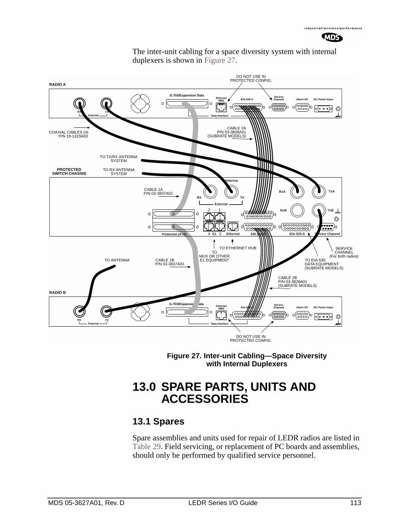
MDS 05-3627A01, Rev. D LEDR Series I/O Guide 113
The inter-unit cabling for a space diversity system with internal duplexers is shown in Figure 27.
Figure 27. Inter-unit Cabling—Space Diversitywith Internal Duplexers
13.0 SPARE PARTS, UNITS AND ACCESSORIES
13.1 Spares
Spare assemblies and units used for repair of LEDR radios are listed in Table 29. Field servicing, or replacement of PC boards and assemblies, should only be performed by qualified service personnel.
DO NOT USE INPROTECTED CONFIG.
TXExternal Data Interface
EIA-530-AEthernetNMS
ServiceChannel Alarm I/O DC Power Input
EIA-530-AEthernetNMS
Data Interface
ServiceChannel Alarm I/O DC Power Input
TO ETHERNET HUB SERVICECHANNEL
(For both radios)
RX
TXExternal
RX
G.703/Expansion Data
G.703/Expansion Data
RADIO A
RADIO B
PROTECTEDSWITCH CHASSIS
DO NOT USE INPROTECTED CONFIG.
CABLE 2AP/N 03-3828A01
(SUBRATE MODELS)
TO TX/RX ANTENNASYSTEM
TOMUX OR OTHERE1 EQUIPMENT TO EIA-530
DATA EQUIPMENT(SUBRATE MODELS)
CABLE 1AP/N 03-3837A02
CABLE 1BP/N 03-3837A02
CABLE 2BP/N 03-3828A01(SUBRATE MODELS)
Antenna
TxA
TxBRxB
530 (A&B)E1
12
34 EIA-530-A Service ChannelEthernetProtected (A+B)
A
B
External
RX TX
RxA
COAXIAL CABLES (4)P/N 19-1323A03
TO RX ANTENNASYSTEM
TO ANTENNA
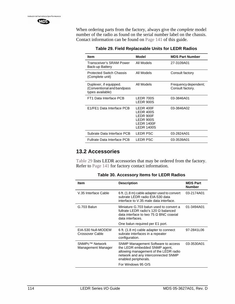
114 LEDR Series I/O Guide MDS 05-3627A01, Rev. D
When ordering parts from the factory, always give the complete model number of the radio as found on the serial number label on the chassis. Contact information can be found on Page 141 of this guide.
13.2 Accessories
Table 29 lists LEDR accessories that may be ordered from the factory. Refer to Page 141 for factory contact information.
Table 29. Field Replaceable Units for LEDR Radios
Item Model MDS Part Number
Transceiver’s SRAM Power Back-up Battery
All Models 27-3109A01
Protected Switch Chassis (Complete unit)
All Models Consult factory
Duplexer, if equipped.(Conventional and bandpass types available)
All Models Frequency dependent; Consult factory.
FT1 Data Interface PCB LEDR 700SLEDR 900S
03-3846A01
E1/FE1 Data Interface PCB LEDR 400FLEDR 400SLEDR 900FLEDR 900SLEDR 1400FLEDR 1400S
03-3846A02
Subrate Data Interface PCB LEDR PSC 03-2824A01
Fullrate Data Interface PCB LEDR PSC 03-3539A01
Table 30. Accessory Items for LEDR Radios
Item Description MDS Part Number
V.35 Interface Cable 6 ft. (1.8 m) cable adapter used to convert subrate LEDR radio EIA-530 data interface to V.35 male data interface.
03-2174A01
G.703 Balun Miniature G.703 balun used to convert a fullrate LEDR radio’s 120 Ω balanced data interface to two 75 Ω BNC coaxial data interfaces.
One balun required per E1 port.
01-3494A01
EIA-530 Null-MODEM Crossover Cable
6 ft. (1.8 m) cable adapter to connect subrate interfaces in a repeater configuration.
97-2841L06
SNMPc™ Network Management Manager
SNMP Management Software to access the LEDR embedded SNMP agent, allowing management of the LEDR radio network and any interconnected SNMP enabled peripherals.
For Windows 95 O/S
03-3530A01
MDS 05-3627A01, Rev. D LEDR Series I/O Guide 115
14.0 FRACTIONAL-T1 INTERFACE CARD 03-3846A01
FRACTIONAL-E1 INTERFACE CARD 03-3846A02
14.1 Introduction
The Fractional-T1 (FT1) and Fractional-E1 (FE1) Interface cards are optional assemblies which provide additional connectivity within a LEDR network for all subrate (S) models. The installation of the FT1/FE1 Interface card inside the radio allows the standard EIA-530 customer data interface to be bypassed and the radio data lines to be con-nected directly to a G.703 T1 or E1 interface.
With the optional FT1/FE1 Interface, users are able to place a LEDR link from a network service access point to a remote site, where an installation supports multiple communications devices. Direct interface to customer equipment, such as channel banks, is possible without the use of expensive protocol converters.
14.2 Fractional-T1/E1 Performance
The FT1 and FE1 Interface allows the LEDR radio to be connected directly with a G.703 T1 or E1 interface. The line rate of the interface operates at the T1 rate of 1.544 Mbps, or E1 rate of 2.048 Mbps. Twelve user selectable DS0 timeslots are transmitted over the air in either case. The FT1 interface is G.703 at 100 Ω line impedance. The FE1 interface is G.703 at 120 Ω line impedance. Physical connection is via an RJ-45 jack on the rear panel.
SNMPc™ Network Management Manager
SNMP Management Software to access the LEDR embedded SNMP agent, allowing management of the LEDR radio network and any interconnected SNMP enabled peripherals.
For Windows 98 or NT O/S.
03-3530A02
Orderwire Handset Voice handset and cord with RJ-11 modular plug.
12-1307A03
Orderwire Handset Kit Voice handset with cord (RJ-11 modular plug), hanger and mounting bracket.
02-1207A01
AC Power Adapter External AC power supply provides 24 Vdc to LEDR radio.
Input: 110 Vac to 240 Vac, 50 to 60 Hz
03-3862A01
DC Power Plug 3-pin keyed connector with binding posts. 73-1194A22
Table 30. Accessory Items for LEDR Radios (Continued)
Item Description MDS Part Number
116 LEDR Series I/O Guide MDS 05-3627A01, Rev. D
14.3 Configurable Parameters
The following performance specifications of the T1 fractional interface are adjustable by the user. All of these parameters are manageable locally, or over the air via SNMP network management. (Refer to the SNMP Handbook, P/N 05-3532A01 for more information.)
Timeslots and Framing
Twelve DS0 timeslots are permitted. In FT1, the timeslot selection is arbitrary. In FE1, timeslot 0 is always sent and the remaining timeslots are arbitrary with the exception of timeslot 16. (Timeslot 16 must be sent when any CAS frame structures are selected.) The selection of timeslots can be different at each end of the link, provided their number is equal. The timeslots may not be reordered.
Alarm signals RAI and AIS are generated as appropriate. The user may optionally have these signals forwarded over the RF link.
The frame formats available for Fractional-T1 operation are as follows:
• FT only• ESF without CRC checking and generation• SF (D4)• SF with JYEL indication• ESF with CRC checking and generation
The frame formats available for Fractional-E1 operation are as follows:
• FAS only• FAS with BSLIP• FAS with CRC• FAS with CRC and BSLIP• FAS and CAS• FAS with CAS and BSLIP• FAS with CAS and CRC• FAS with CAS• CRC and BSLIP.
The re-framing criteria may be adjusted to the following settings: 2 out of 4 Fbit errors, 2 out of 5 Fbit errors, 2 out of 6 Fbit errors. For FE1, the reframing criteria is selectable between consecutive FAS errors or CRC errors.
Line Codes
The following standard T1 line codes are supported: B8ZS, AMI, and per-channel B7ZS.
The following standard E1 line codes are supported: HDB3 and AMI.
MDS 05-3627A01, Rev. D LEDR Series I/O Guide 117
Diagnostics
The T1 line at each end of the link may be tested using a variety of bit patterns. In normal operation, statistics are stored for any errors occur-ring at the line interface, such as framing errors, bipolar violations, and CRC errors.
Data may be looped back at the local port, through the T1 option only, and at the remote unit. Further, the unit will respond to in-band (SF) and data link (ESF) loopback codes at the local port.
When in ESF framing mode, the option can automatically generate per-formance report messages.
The following alarms may be monitored & logged. They may also be associated with a user-selectable indication (alarm contact or front panel LED): Remote Loopback, Lost Frame, Lost Signal, Lost Analog Signal, AIS, RAI (RYEL), MultiFrame RAI, Severely Errored Frame, Frame Re-Align, MultiFrame AIS, Far End Block Error, Line Code Error, CRC Errors and Frame Bit Error.
Clocking
The clock source is configurable for network, loopback, and internal timing, with secondary selections available should the primary source become faulty. Refer to the discussion of the clkmode command (Page 55) for more information
14.4 Field Installation of the FT1 Interface Board
An “S” Series LEDR radio can be fitted with a Fractional-T1 (FT1) or Fractional-E1 (FE1)Interface Board (Figure 28). The addition of an FT1/FE1 board enables the radio to operate with a G.703 interface at speeds up to 768 kbps.
To add the FT1/FE1 Interface Board to an existing LEDR radio trans-ceiver, follow these steps:
1. Remove the top cover of the radio (4 Phillips screws).
2. Identify the installation area for the Interface Board (See Figure 29). Remove the three Phillips screws on the main PC board which cor-respond to the mounting holes on the Interface Board.
3. Install the threaded standoff spacers (furnished with the option board) onto the main PC board in the holes formerly occupied by the screws. (Note: Washers must not be used between the standoff spac-ers and either of the PC boards.)
4. Locate connectors J912 and J913 (See Figure 29). These connectors mate with the plugs on the bottom of the Interface board.
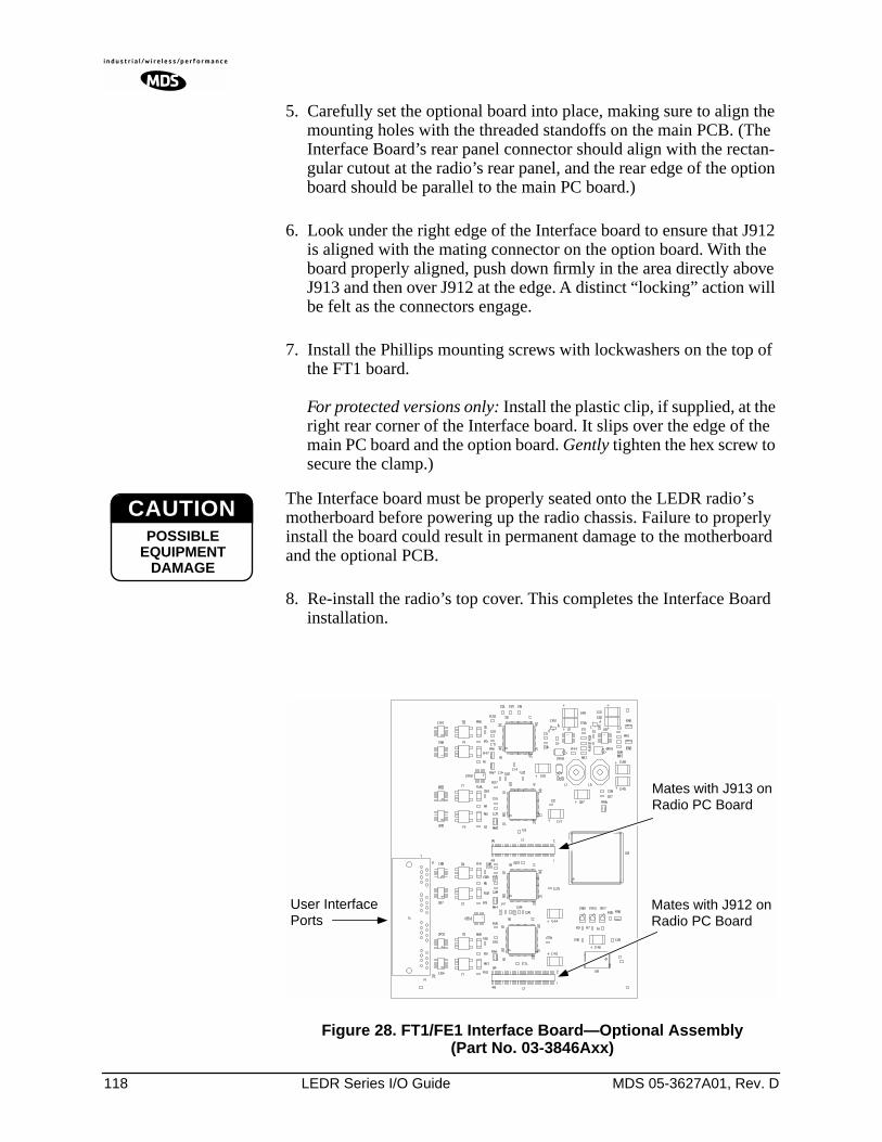
118 LEDR Series I/O Guide MDS 05-3627A01, Rev. D
5. Carefully set the optional board into place, making sure to align the mounting holes with the threaded standoffs on the main PCB. (The Interface Board’s rear panel connector should align with the rectan-gular cutout at the radio’s rear panel, and the rear edge of the option board should be parallel to the main PC board.)
6. Look under the right edge of the Interface board to ensure that J912 is aligned with the mating connector on the option board. With the board properly aligned, push down firmly in the area directly above J913 and then over J912 at the edge. A distinct “locking” action will be felt as the connectors engage.
7. Install the Phillips mounting screws with lockwashers on the top of the FT1 board.
For protected versions only: Install the plastic clip, if supplied, at the right rear corner of the Interface board. It slips over the edge of the main PC board and the option board. Gently tighten the hex screw to secure the clamp.)
The Interface board must be properly seated onto the LEDR radio’s motherboard before powering up the radio chassis. Failure to properly install the board could result in permanent damage to the motherboard and the optional PCB.
8. Re-install the radio’s top cover. This completes the Interface Board installation.
Invisible place holder
Figure 28. FT1/FE1 Interface Board—Optional Assembly(Part No. 03-3846Axx)
CAUTIONPOSSIBLE
EQUIPMENTDAMAGE
User InterfacePorts
Mates with J912 onRadio PC Board
Mates with J913 onRadio PC Board
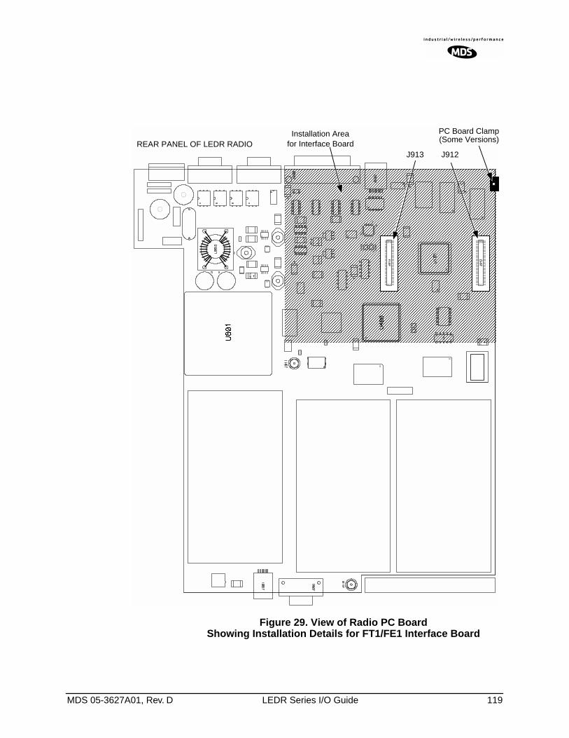
MDS 05-3627A01, Rev. D LEDR Series I/O Guide 119
Invisible place holder
Figure 29. View of Radio PC BoardShowing Installation Details for FT1/FE1 Interface Board
J912J913REAR PANEL OF LEDR RADIO
Installation Areafor Interface Board
PC Board Clamp(Some Versions)
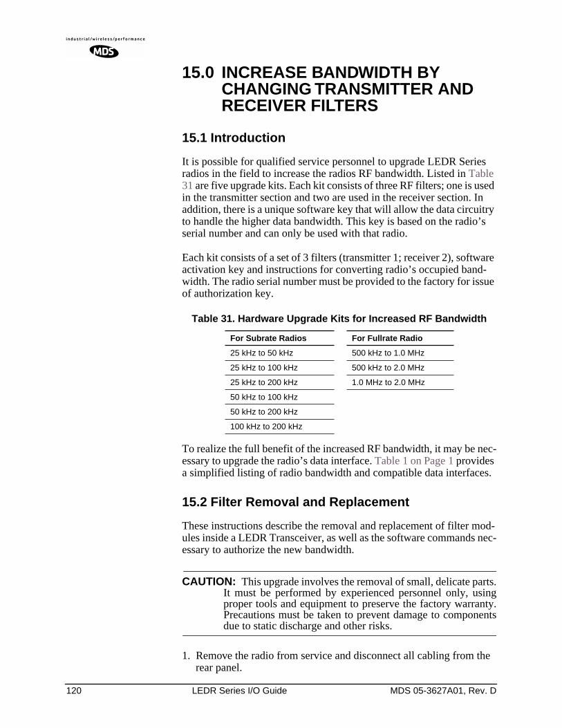
120 LEDR Series I/O Guide MDS 05-3627A01, Rev. D
15.0 INCREASE BANDWIDTH BY CHANGING TRANSMITTER AND RECEIVER FILTERS
15.1 Introduction
It is possible for qualified service personnel to upgrade LEDR Series radios in the field to increase the radios RF bandwidth. Listed in Table 31 are five upgrade kits. Each kit consists of three RF filters; one is used in the transmitter section and two are used in the receiver section. In addition, there is a unique software key that will allow the data circuitry to handle the higher data bandwidth. This key is based on the radio’s serial number and can only be used with that radio.
Each kit consists of a set of 3 filters (transmitter 1; receiver 2), software activation key and instructions for converting radio’s occupied band-width. The radio serial number must be provided to the factory for issue of authorization key.
To realize the full benefit of the increased RF bandwidth, it may be nec-essary to upgrade the radio’s data interface. Table 1 on Page 1 provides a simplified listing of radio bandwidth and compatible data interfaces.
15.2 Filter Removal and Replacement
These instructions describe the removal and replacement of filter mod-ules inside a LEDR Transceiver, as well as the software commands nec-essary to authorize the new bandwidth.
CAUTION: This upgrade involves the removal of small, delicate parts.It must be performed by experienced personnel only, usingproper tools and equipment to preserve the factory warranty.Precautions must be taken to prevent damage to componentsdue to static discharge and other risks.
1. Remove the radio from service and disconnect all cabling from the rear panel.
Table 31. Hardware Upgrade Kits for Increased RF Bandwidth
For Subrate Radios For Fullrate Radio
25 kHz to 50 kHz 500 kHz to 1.0 MHz
25 kHz to 100 kHz 500 kHz to 2.0 MHz
25 kHz to 200 kHz 1.0 MHz to 2.0 MHz
50 kHz to 100 kHz
50 kHz to 200 kHz
100 kHz to 200 kHz
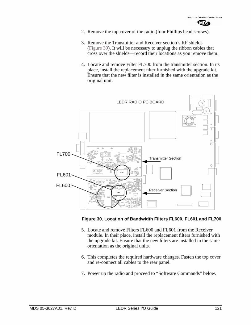
MDS 05-3627A01, Rev. D LEDR Series I/O Guide 121
2. Remove the top cover of the radio (four Phillips head screws).
3. Remove the Transmitter and Receiver section’s RF shields (Figure 30). It will be necessary to unplug the ribbon cables that cross over the shields—record their locations as you remove them.
4. Locate and remove Filter FL700 from the transmitter section. In its place, install the replacement filter furnished with the upgrade kit. Ensure that the new filter is installed in the same orientation as the original unit.
Invisible place holder
Figure 30. Location of Bandwidth Filters FL600, FL601 and FL700
5. Locate and remove Filters FL600 and FL601 from the Receiver module. In their place, install the replacement filters furnished with the upgrade kit. Ensure that the new filters are installed in the same orientation as the original units.
6. This completes the required hardware changes. Fasten the top cover and re-connect all cables to the rear panel.
7. Power up the radio and proceed to “Software Commands” below.
LEDR RADIO PC BOARD
FL700
FL601
FL600
Transmitter Section
Receiver Section
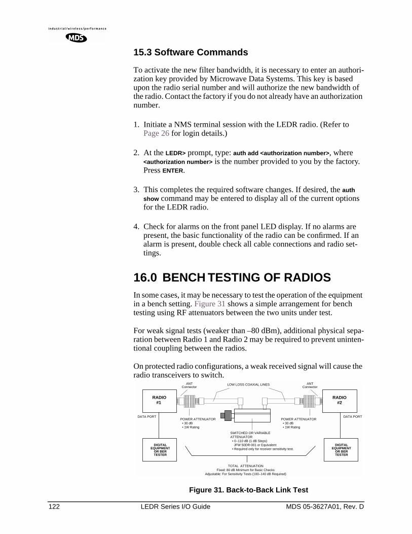
122 LEDR Series I/O Guide MDS 05-3627A01, Rev. D
15.3 Software Commands
To activate the new filter bandwidth, it is necessary to enter an authori-zation key provided by Microwave Data Systems. This key is based upon the radio serial number and will authorize the new bandwidth of the radio. Contact the factory if you do not already have an authorization number.
1. Initiate a NMS terminal session with the LEDR radio. (Refer to Page 26 for login details.)
2. At the LEDR> prompt, type: auth add <authorization number>, where <authorization number> is the number provided to you by the factory. Press ENTER.
3. This completes the required software changes. If desired, the auth show command may be entered to display all of the current options for the LEDR radio.
4. Check for alarms on the front panel LED display. If no alarms are present, the basic functionality of the radio can be confirmed. If an alarm is present, double check all cable connections and radio set-tings.
16.0 BENCH TESTING OF RADIOSIn some cases, it may be necessary to test the operation of the equipment in a bench setting. Figure 31 shows a simple arrangement for bench testing using RF attenuators between the two units under test.
For weak signal tests (weaker than –80 dBm), additional physical sepa-ration between Radio 1 and Radio 2 may be required to prevent uninten-tional coupling between the radios.
On protected radio configurations, a weak received signal will cause the radio transceivers to switch.
Figure 31. Back-to-Back Link Test
ANTConnector
ANTConnector
POWER ATTENUATOR • 30 dB • 1W Rating
POWER ATTENUATOR • 30 dB • 1W Rating
SWITCHED OR VARIABLEATTENUATOR • 0–110 dB (1 dB Steps) JFW 50DR-001 or Equivalent • Required only for receiver sensitivity test.
LOW LOSS COAXIAL LINES
DIGITALEQUIPMENT
OR BERTESTER
RADIO#1
DATA PORT
TOTAL ATTENUATIONFixed: 80 dB Minimum for Basic Checks
Adjustable: For Sensitivity Tests (100–140 dB Required)
DIGITALEQUIPMENT
OR BERTESTER
DATA PORT
RADIO#2
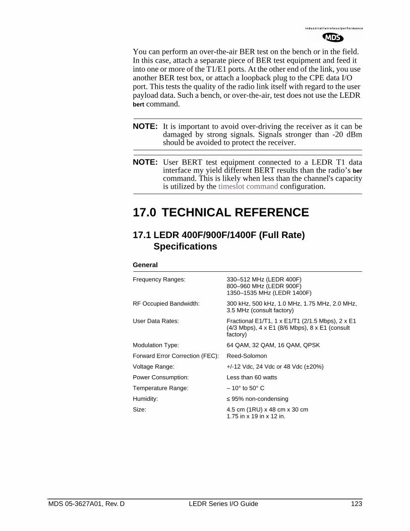
MDS 05-3627A01, Rev. D LEDR Series I/O Guide 123
You can perform an over-the-air BER test on the bench or in the field. In this case, attach a separate piece of BER test equipment and feed it into one or more of the T1/E1 ports. At the other end of the link, you use another BER test box, or attach a loopback plug to the CPE data I/O port. This tests the quality of the radio link itself with regard to the user payload data. Such a bench, or over-the-air, test does not use the LEDR bert command.
NOTE: It is important to avoid over-driving the receiver as it can bedamaged by strong signals. Signals stronger than -20 dBmshould be avoided to protect the receiver.
NOTE: User BERT test equipment connected to a LEDR T1 datainterface my yield different BERT results than the radio’s bercommand. This is likely when less than the channel's capacityis utilized by the timeslot command configuration.
17.0 TECHNICAL REFERENCE
17.1 LEDR 400F/900F/1400F (Full Rate) Specifications
General
Frequency Ranges: 330–512 MHz (LEDR 400F)800–960 MHz (LEDR 900F)1350–1535 MHz (LEDR 1400F)
RF Occupied Bandwidth: 300 kHz, 500 kHz, 1.0 MHz, 1.75 MHz, 2.0 MHz, 3.5 MHz (consult factory)
User Data Rates: Fractional E1/T1, 1 x E1/T1 (2/1.5 Mbps), 2 x E1 (4/3 Mbps), 4 x E1 (8/6 Mbps), 8 x E1 (consult factory)
Modulation Type: 64 QAM, 32 QAM, 16 QAM, QPSK
Forward Error Correction (FEC): Reed-Solomon
Voltage Range: +/-12 Vdc, 24 Vdc or 48 Vdc (±20%)
Power Consumption: Less than 60 watts
Temperature Range: – 10° to 50° C
Humidity: ≤ 95% non-condensing
Size: 4.5 cm (1RU) x 48 cm x 30 cm1.75 in x 19 in x 12 in.
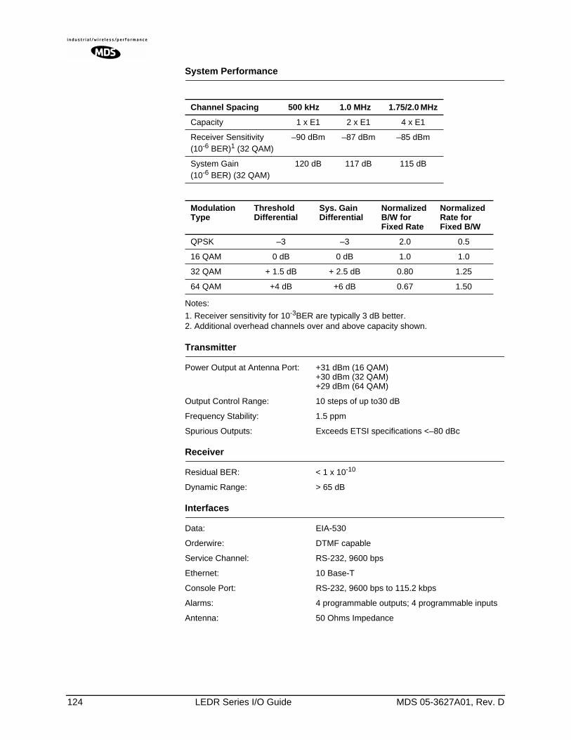
124 LEDR Series I/O Guide MDS 05-3627A01, Rev. D
System Performance
Notes:
1. Receiver sensitivity for 10-3BER are typically 3 dB better.2. Additional overhead channels over and above capacity shown.
Transmitter
Power Output at Antenna Port: +31 dBm (16 QAM)+30 dBm (32 QAM)+29 dBm (64 QAM)
Output Control Range: 10 steps of up to30 dB
Frequency Stability: 1.5 ppm
Spurious Outputs: Exceeds ETSI specifications <–80 dBc
Receiver
Residual BER: < 1 x 10⁻¹⁰
Dynamic Range: > 65 dB
Interfaces
Data: EIA-530
Orderwire: DTMF capable
Service Channel: RS-232, 9600 bps
Ethernet: 10 Base-T
Console Port: RS-232, 9600 bps to 115.2 kbps
Alarms: 4 programmable outputs; 4 programmable inputs
Antenna: 50 Ohms Impedance
Channel Spacing 500 kHz 1.0 MHz 1.75/2.0 MHz
Capacity 1 x E1 2 x E1 4 x E1
Receiver Sensitivity(10-6 BER)1 (32 QAM)
–90 dBm –87 dBm –85 dBm
System Gain(10-6 BER) (32 QAM)
120 dB 117 dB 115 dB
ModulationType
Threshold Differential
Sys. Gain Differential
Normalized B/W for Fixed Rate
Normalized Rate for Fixed B/W
QPSK –3 –3 2.0 0.5
16 QAM 0 dB 0 dB 1.0 1.0
32 QAM + 1.5 dB + 2.5 dB 0.80 1.25
64 QAM +4 dB +6 dB 0.67 1.50
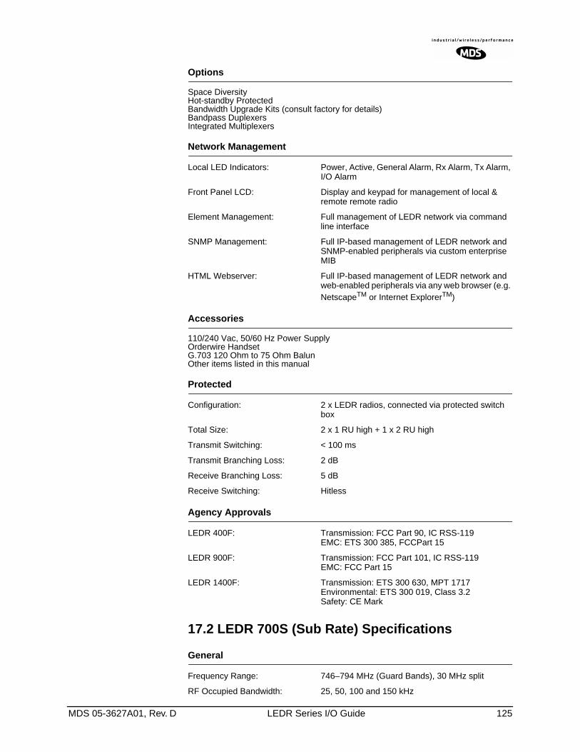
MDS 05-3627A01, Rev. D LEDR Series I/O Guide 125
Options
Space DiversityHot-standby ProtectedBandwidth Upgrade Kits (consult factory for details)Bandpass DuplexersIntegrated Multiplexers
Network Management
Local LED Indicators: Power, Active, General Alarm, Rx Alarm, Tx Alarm, I/O Alarm
Front Panel LCD: Display and keypad for management of local & remote remote radio
Element Management: Full management of LEDR network via command line interface
SNMP Management: Full IP-based management of LEDR network and SNMP-enabled peripherals via custom enterprise MIB
HTML Webserver: Full IP-based management of LEDR network and web-enabled peripherals via any web browser (e.g. NetscapeTM or Internet ExplorerTM)
Accessories
110/240 Vac, 50/60 Hz Power SupplyOrderwire HandsetG.703 120 Ohm to 75 Ohm BalunOther items listed in this manual
Protected
Configuration: 2 x LEDR radios, connected via protected switch box
Total Size: 2 x 1 RU high + 1 x 2 RU high
Transmit Switching: < 100 ms
Transmit Branching Loss: 2 dB
Receive Branching Loss: 5 dB
Receive Switching: Hitless
Agency Approvals
LEDR 400F: Transmission: FCC Part 90, IC RSS-119EMC: ETS 300 385, FCCPart 15
LEDR 900F: Transmission: FCC Part 101, IC RSS-119EMC: FCC Part 15
LEDR 1400F: Transmission: ETS 300 630, MPT 1717Environmental: ETS 300 019, Class 3.2Safety: CE Mark
17.2 LEDR 700S (Sub Rate) Specifications
General
Frequency Range: 746–794 MHz (Guard Bands), 30 MHz split
RF Occupied Bandwidth: 25, 50, 100 and 150 kHz
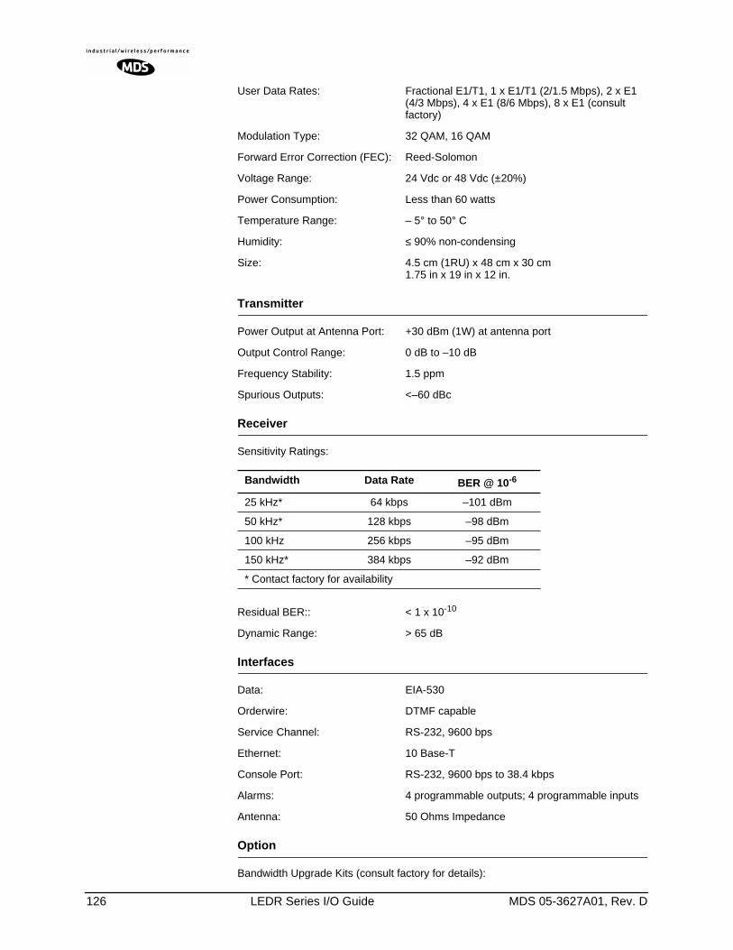
126 LEDR Series I/O Guide MDS 05-3627A01, Rev. D
User Data Rates: Fractional E1/T1, 1 x E1/T1 (2/1.5 Mbps), 2 x E1 (4/3 Mbps), 4 x E1 (8/6 Mbps), 8 x E1 (consult factory)
Modulation Type: 32 QAM, 16 QAM
Forward Error Correction (FEC): Reed-Solomon
Voltage Range: 24 Vdc or 48 Vdc (±20%)
Power Consumption: Less than 60 watts
Temperature Range: – 5° to 50° C
Humidity: ≤ 90% non-condensing
Size: 4.5 cm (1RU) x 48 cm x 30 cm1.75 in x 19 in x 12 in.
Transmitter
Power Output at Antenna Port: +30 dBm (1W) at antenna port
Output Control Range: 0 dB to –10 dB
Frequency Stability: 1.5 ppm
Spurious Outputs: <–60 dBc
Receiver
Sensitivity Ratings:
Residual BER:: < 1 x 10⁻¹⁰
Dynamic Range: > 65 dB
Interfaces
Data: EIA-530
Orderwire: DTMF capable
Service Channel: RS-232, 9600 bps
Ethernet: 10 Base-T
Console Port: RS-232, 9600 bps to 38.4 kbps
Alarms: 4 programmable outputs; 4 programmable inputs
Antenna: 50 Ohms Impedance
Option
Bandwidth Upgrade Kits (consult factory for details):
Bandwidth Data Rate BER @ 10-6
25 kHz* 64 kbps –101 dBm
50 kHz* 128 kbps –98 dBm
100 kHz 256 kbps –95 dBm
150 kHz* 384 kbps –92 dBm
* Contact factory for availability
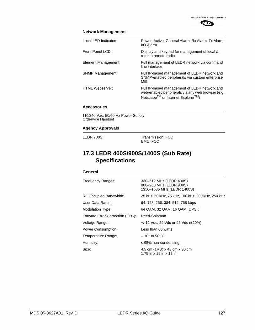
MDS 05-3627A01, Rev. D LEDR Series I/O Guide 127
Network Management
Local LED Indicators: Power, Active, General Alarm, Rx Alarm, Tx Alarm, I/O Alarm
Front Panel LCD: Display and keypad for management of local & remote remote radio
Element Management: Full management of LEDR network via command line interface
SNMP Management: Full IP-based management of LEDR network and SNMP-enabled peripherals via custom enterprise MIB
HTML Webserver: Full IP-based management of LEDR network and web-enabled peripherals via any web browser (e.g. NetscapeTM or Internet ExplorerTM)
Accessories
110/240 Vac, 50/60 Hz Power SupplyOrderwire Handset
Agency Approvals
LEDR 700S: Transmission: FCCEMC: FCC
17.3 LEDR 400S/900S/1400S (Sub Rate) Specifications
General
Frequency Ranges: 330–512 MHz (LEDR 400S)800–960 MHz (LEDR 900S)1350–1535 MHz (LEDR 1400S)
RF Occupied Bandwidth: 25 kHz, 50 kHz, 75 kHz, 100 kHz, 200 kHz, 250 kHz
User Data Rates: 64, 128. 256, 384, 512, 768 kbps
Modulation Type: 64 QAM, 32 QAM, 16 QAM, QPSK
Forward Error Correction (FEC): Reed-Solomon
Voltage Range: +/-12 Vdc, 24 Vdc or 48 Vdc (±20%)
Power Consumption: Less than 60 watts
Temperature Range: – 10° to 50° C
Humidity: ≤ 95% non-condensing
Size: 4.5 cm (1RU) x 48 cm x 30 cm1.75 in x 19 in x 12 in.
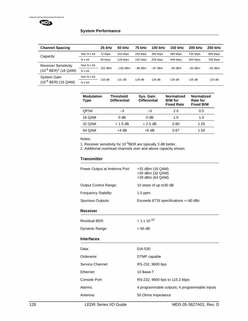
128 LEDR Series I/O Guide MDS 05-3627A01, Rev. D
System Performance
Notes:
1. Receiver sensitivity for 10-3BER are typically 3 dB better.2. Additional overhead channels over and above capacity shown.
Transmitter
Power Output at Antenna Port: +31 dBm (16 QAM)+30 dBm (32 QAM)+29 dBm (64 QAM)
Output Control Range: 10 steps of up to30 dB
Frequency Stability: 1.5 ppm
Spurious Outputs: Exceeds ETSI specifications <–80 dBc
Receiver
Residual BER: < 1 x 10⁻¹⁰
Dynamic Range: > 65 dB
Interfaces
Data: EIA-530
Orderwire: DTMF capable
Service Channel: RS-232, 9600 bps
Ethernet: 10 Base-T
Console Port: RS-232, 9600 bps to 115.2 kbps
Alarms: 4 programmable outputs; 4 programmable inputs
Antenna: 50 Ohms Impedance
Channel Spacing 25 kHz 50 kHz 75 kHz 100 kHz 150 kHz 200 kHz 250 kHz
CapacityNon N x 64 72 kbps 152 kbps 240 kbps 360 kbps 480 kbps 700 kbps 800 kbps
N x 64 64 kbps 128 kbps 192 kbps 256 kbps 448 kbps 640 kbps 768 kbps
Receiver Sensitivity(10-6 BER)1 (16 QAM)
Non N x 64102 dBm –100 dBm –98 dBm –97 dBm –95 dBm –94 dBm –92 dBm
N x 64
System Gain(10-6 BER) (16 QAM)
Non N x 64133 dB 131 dB 129 dB 128 dB 126 dB 125 dB 123 dB
N x 64
ModulationType
Threshold Differential
Sys. Gain Differential
Normalized B/W for Fixed Rate
Normalized Rate for Fixed B/W
QPSK –3 –3 2.0 0.5
16 QAM 0 dB 0 dB 1.0 1.0
32 QAM + 1.5 dB + 2.5 dB 0.80 1.25
64 QAM +4 dB +6 dB 0.67 1.50
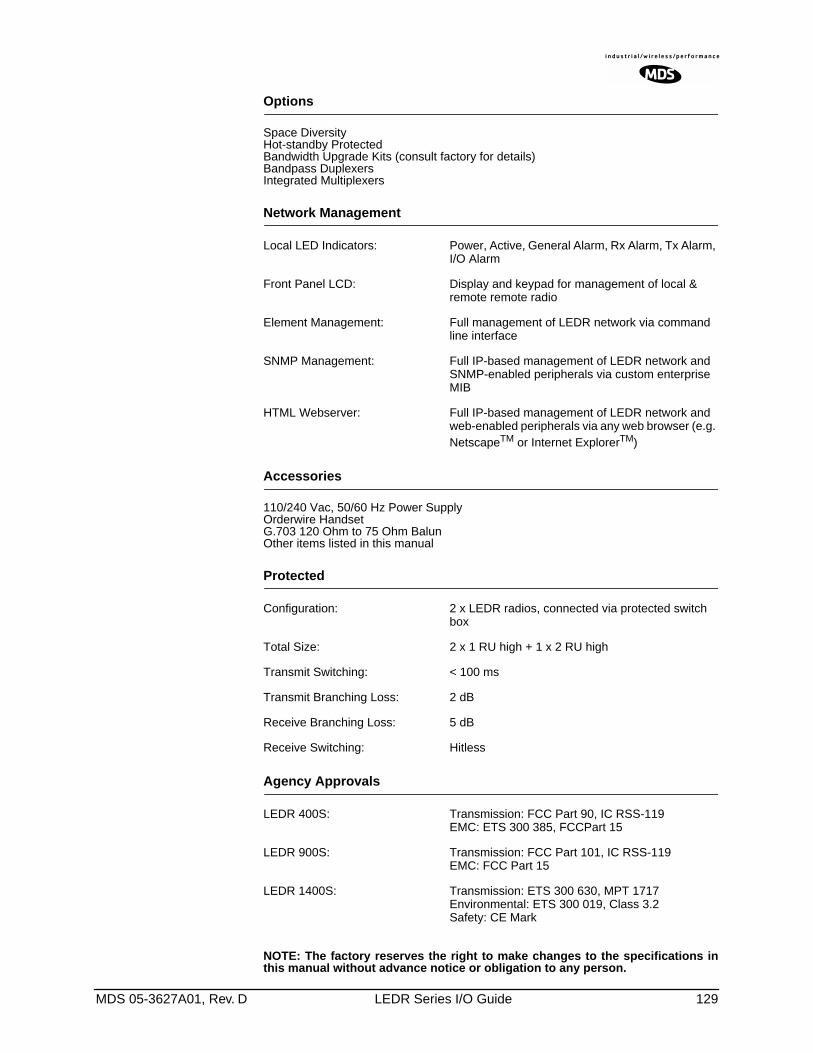
MDS 05-3627A01, Rev. D LEDR Series I/O Guide 129
Options
Space DiversityHot-standby ProtectedBandwidth Upgrade Kits (consult factory for details)Bandpass DuplexersIntegrated Multiplexers
Network Management
Local LED Indicators: Power, Active, General Alarm, Rx Alarm, Tx Alarm, I/O Alarm
Front Panel LCD: Display and keypad for management of local & remote remote radio
Element Management: Full management of LEDR network via command line interface
SNMP Management: Full IP-based management of LEDR network and SNMP-enabled peripherals via custom enterprise MIB
HTML Webserver: Full IP-based management of LEDR network and web-enabled peripherals via any web browser (e.g. NetscapeTM or Internet ExplorerTM)
Accessories
110/240 Vac, 50/60 Hz Power SupplyOrderwire HandsetG.703 120 Ohm to 75 Ohm BalunOther items listed in this manual
Protected
Configuration: 2 x LEDR radios, connected via protected switch box
Total Size: 2 x 1 RU high + 1 x 2 RU high
Transmit Switching: < 100 ms
Transmit Branching Loss: 2 dB
Receive Branching Loss: 5 dB
Receive Switching: Hitless
Agency Approvals
LEDR 400S: Transmission: FCC Part 90, IC RSS-119EMC: ETS 300 385, FCCPart 15
LEDR 900S: Transmission: FCC Part 101, IC RSS-119EMC: FCC Part 15
LEDR 1400S: Transmission: ETS 300 630, MPT 1717Environmental: ETS 300 019, Class 3.2Safety: CE Mark
NOTE: The factory reserves the right to make changes to the specifications inthis manual without advance notice or obligation to any person.
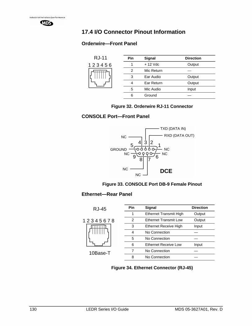
130 LEDR Series I/O Guide MDS 05-3627A01, Rev. D
17.4 I/O Connector Pinout Information
Orderwire—Front PanelInvisible place holder
Figure 32. Orderwire RJ-11 Connector
CONSOLE Port—Front PanelInvisible place holder
Figure 33. CONSOLE Port DB-9 Female Pinout
Ethernet—Rear PanelInvisible place holder
Figure 34. Ethernet Connector (RJ-45)
1 2 3 4 5 6
p
Pin Signal Direction
1 + 12 Vdc Output
2 Mic Return —
3 Ear Audio Output
4 Ear Return Output
5 Mic Audio Input
6 Ground —
RJ-11
6789
1234
5NC
RXD (DATA OUT)
TXD (DATA IN)
NC
NC
NC
NC
NCGROUND
DCE
1 2 3 4 5 6 7 8
RJ-45
10Base-T
Pin Signal Direction
1 Ethernet Transmit High Output
2 Ethernet Transmit Low Output
3 Ethernet Receive High Input
4 No Connection —
5 No Connection —
6 Ethernet Receive Low Input
7 No Connection —
8 No Connection —
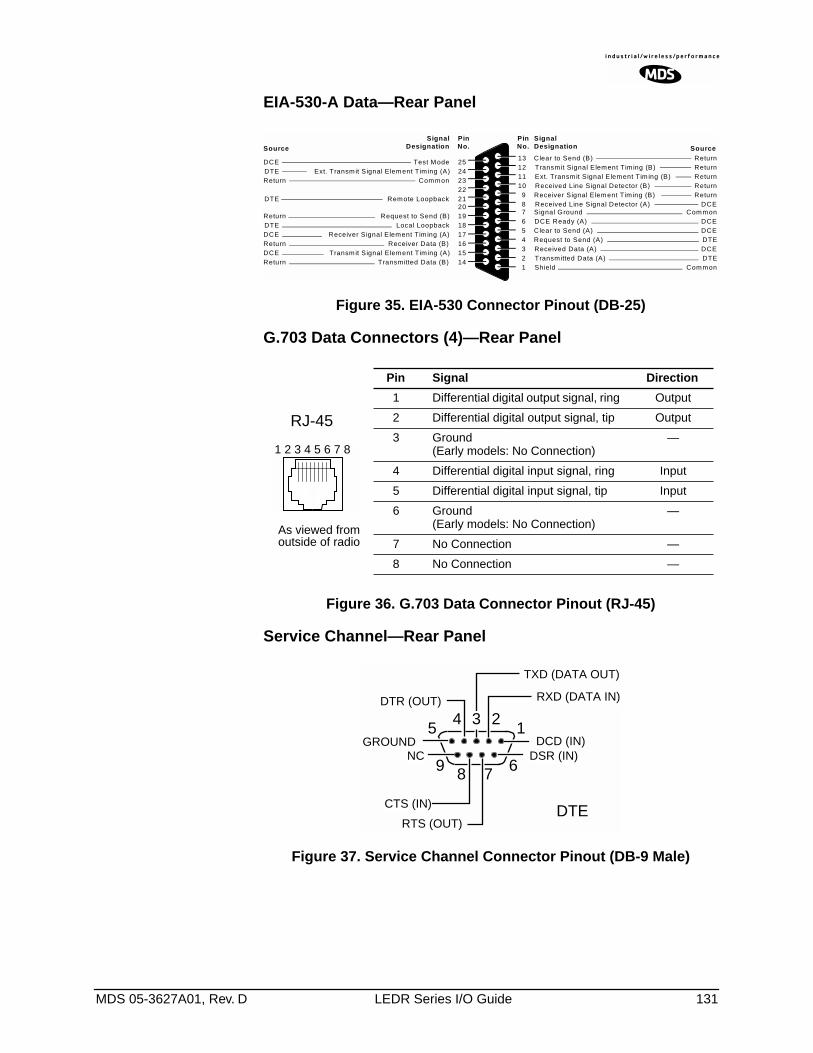
MDS 05-3627A01, Rev. D LEDR Series I/O Guide 131
EIA-530-A Data—Rear PanelInvisible place holder
Figure 35. EIA-530 Connector Pinout (DB-25)
G.703 Data Connectors (4)—Rear PanelInvisible place holder
Figure 36. G.703 Data Connector Pinout (RJ-45)
Service Channel—Rear PanelInvisible place holder
Figure 37. Service Channel Connector Pinout (DB-9 Male)
Clear to Send (B)Transmit Signal Element Tim ing (B)Ext. Transmit Signal Element Tim ing (B)
13121110
987654321
Received Line Signal Detector (B)Receiver Signal Element Tim ing (B)Received Line Signal Detector (A)Signal GroundDCE Ready (A)Clear to Send (A)Request to Send (A)Received Data (A)Transmitted Data (A)Shield
ReturnReturnReturnReturnReturn
DCECommon
DCEDCEDTEDCEDTE
Common
252423222120191817161514
Test ModeExt. Transmit Signal Element Tim ing (A)
Common
Remote Loopback
Request to Send (B)Local Loopback
Receiver Signal Element Tim ing (A)Receiver Data (B)
Transmit Signal Element Tim ing (A)Transmitted Data (B)
DCEDTEReturn
DTE
ReturnDTEDCEReturnDCEReturn
Source
SignalDesignation
PinNo.
PinNo.
SignalDesignation Source
Pin Signal Direction
1 Differential digital output signal, ring Output
2 Differential digital output signal, tip Output
3 Ground(Early models: No Connection)
—
4 Differential digital input signal, ring Input
5 Differential digital input signal, tip Input
6 Ground(Early models: No Connection)
—
7 No Connection —
8 No Connection —
1 2 3 4 5 6 7 8
RJ-45
As viewed fromoutside of radio
6789
1234
5DCD (IN)
RXD (DATA IN)
TXD (DATA OUT)
DTR (OUT)
DSR (IN)
RTS (OUT)
CTS (IN)
NCGROUND
DTE
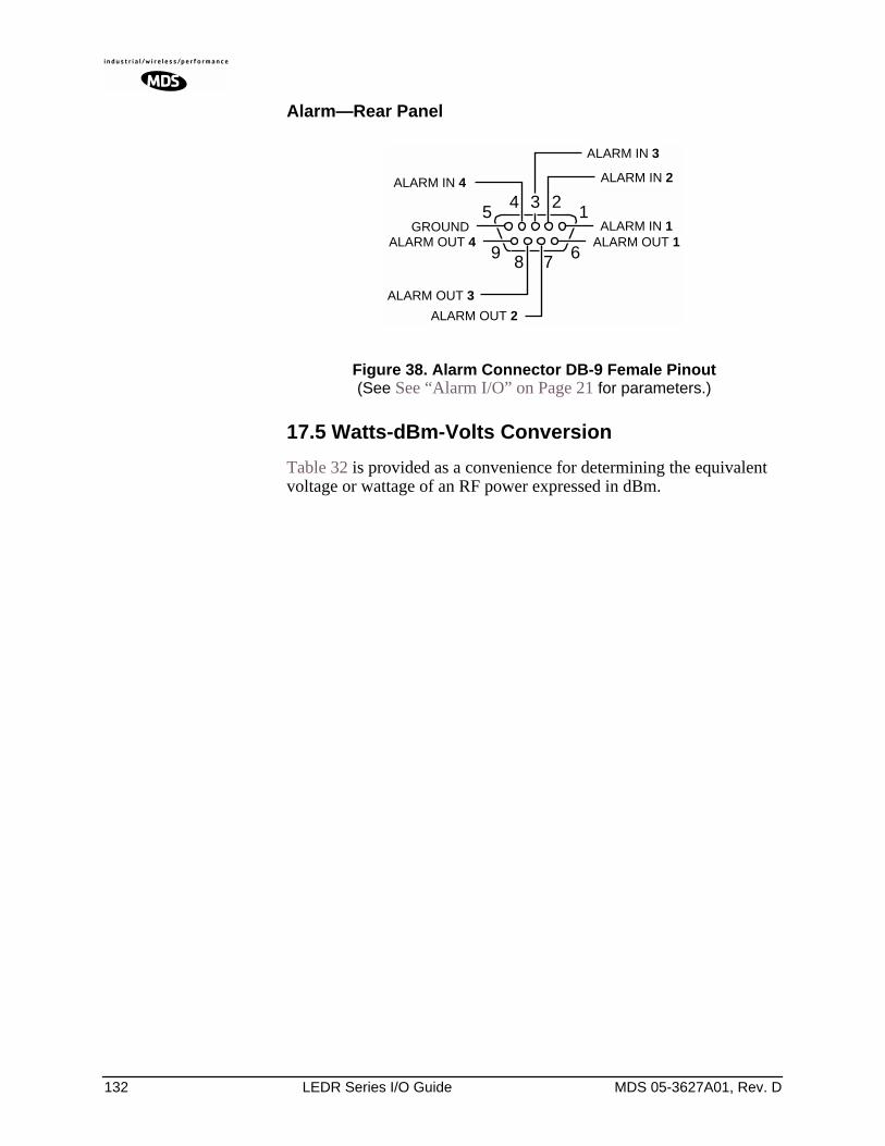
132 LEDR Series I/O Guide MDS 05-3627A01, Rev. D
Alarm—Rear PanelInvisible place holder
Invisible place holder
Figure 38. Alarm Connector DB-9 Female Pinout(See See “Alarm I/O” on Page 21 for parameters.)
17.5 Watts-dBm-Volts Conversion
Table 32 is provided as a convenience for determining the equivalent voltage or wattage of an RF power expressed in dBm.
6789
1234
5ALARM IN 1
ALARM IN 2
ALARM IN 3
ALARM IN 4
ALARM OUT 1
ALARM OUT 2
ALARM OUT 3
ALARM OUT 4GROUND
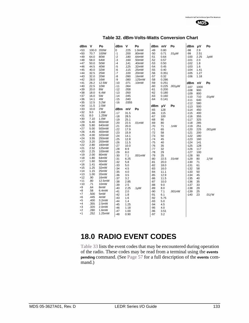
MDS 05-3627A01, Rev. D LEDR Series I/O Guide 133
Invisible place holder
18.0 RADIO EVENT CODESTable 33 lists the event codes that may be encountered during operation of the radio. These codes may be read from a terminal using the events pending command. (See Page 57 for a full description of the events com-mand.)
Table 32. dBm-Volts-Watts Conversion Chart
dBm V Po+53 100.0 200W+50 70.7 100W+49 64.0 80W+48 58.0 64W+47 50.0 50W+46 44.5 40W+45 40.0 32W+44 32.5 25W+43 32.0 20W+42 28.0 16W+41 26.2 12.5W+40 22.5 10W+39 20.0 8W+38 18.0 6.4W+37 16.0 5W+36 14.1 4W+35 12.5 3.2W+34 11.5 2.5W+33 10.0 2W+32 9.0 1.6W+31 8.0 1.25W+30 7.10 1.0W+29 6.40 800mW+28 5.80 640mW+27 5.00 500mW+26 4.45 400mW+25 4.00 320mW+24 3.55 250mW+23 3.20 200mW+22 2.80 160mW+21 2.52 125mW+20 2.25 100mW+19 2.00 80mW+18 1.80 64mW+17 1.60 50mW+16 1.41 40mW+15 1.25 32mW+14 1.15 25mW+13 1.00 20mW+12 .90 16mW+11 .80 12.5mW+10 .71 10mW+9 .64 8mW+8 .58 6.4mW+7 .500 5mW+6 .445 4mW+5 .400 3.2mW+4 .355 2.5mW+3 .320 2.0mW+2 .280 1.6mW+1 .252 1.25mW
dBm V Po0 .225 1.0mW-1 .200 .80mW-2 .180 .64mW-3 .160 .50mW-4 .141 .40mW-5 .125 .32mW-6 .115 .25mW-7 .100 .20mW-8 .090 .16mW-9 .080 .125mW-10 .071 .10mW-11 .064-12 .058-13 .050-14 .045-15 .040-16 .0355
dBm mV Po-17 31.5-18 28.5-19 25.1-20 22.5 .01mW-21 20.0-22 17.9-23 15.9-24 14.1-25 12.8-26 11.5-27 10.0-28 8.9-29 8.0-30 7.1 .001mW-31 6.25-32 5.8-33 5.0-34 4.5-35 4.0-36 3.5-37 3.2-38 2.85-39 2.5-40 2.25 .1µW-41 2.0-42 1.8-43 1.6-44 1.4-45 1.25-46 1.18-47 1.00-48 0.90
dBm mV Po-49 0.80-50 0.71 .01µW-51 0.64-52 0.57-53 0.50-54 0.45-55 0.40-56 0.351-57 0.32-58 0.286-59 0.251-60 0.225 .001µW-61 0.200-62 0.180-63 0.160-64 0.141
dBm µV Po-65 128-66 115-67 100-68 90-69 80-70 71 .1nW-71 65-72 58-73 50-74 45-75 40-76 35-77 32-78 29-79 25-80 22.5 .01nW-81 20.0-82 18.0-83 16.0-84 11.1-85 12.9-86 11.5-87 10.0-88 9.0-89 8.0-90 7.1 .001nW-91 6.1-92 5.75-93 5.0-94 4.5-95 4.0-96 3.51-97 3.2
dBm µV Po-98 2.9-99 2.51-100 2.25 .1pW-101 2.0-102 1.8-103 1.6-104 1.41-105 1.27-106 1.18
dBm nV Po-107 1000-108 900-109 800-110 710 .01pW-111 640-112 580-113 500-114 450-115 400-116 355-117 325-118 285-119 251-120 225 .001pW-121 200-122 180-123 160-124 141-125 128-126 117-127 100-128 90-129 80 .1ƒW-130 71-131 61-132 58-133 50-134 45-135 40-136 35-137 33-138 29-139 25-140 23 .01ƒW
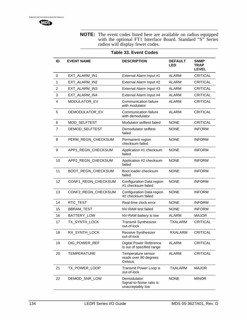
134 LEDR Series I/O Guide MDS 05-3627A01, Rev. D
NOTE: The event codes listed here are available on radios equippedwith the optional FT1 Interface Board. Standard “S” Seriesradios will display fewer codes.
Table 33. Event Codes
ID EVENT NAME DESCRIPTION DEFAULTLED
SNMP TRAP LEVEL
0 EXT_ALARM_IN1 External Alarm Input #1 ALARM CRITICAL
1 EXT_ALARM_IN2 External Alarm Input #2 ALARM CRITICAL
2 EXT_ALARM_IN3 External Alarm Input #3 ALARM CRITICAL
3 EXT_ALARM_IN4 External Alarm Input #4 ALARM CRITICAL
4 MODULATOR_EV Communication failure with modulator
ALARM CRITICAL
5 DEMODULATOR_EV Communication failure with demodulator
ALARM CRITICAL
6 MOD_SELFTEST Modulator selftest failed NONE CRITICAL
7 DEMOD_SELFTEST Demodulator selftest failed
NONE INFORM
8 PERM_REGN_CHECKSUM Permanent region checksum failed
NONE INFORM
9 APP1_REGN_CHECKSUM Application #1 checksum failed
NONE INFORM
10 APP2_REGN_CHECKSUM Application #2 checksum failed
NONE INFORM
11 BOOT_REGN_CHECKSUM Boot loader checksum failed
NONE INFORM
12 CONF1_REGN_CHECKSUM Configuration Data region #1 checksum failed
NONE INFORM
13 CONF2_REGN_CHECKSUM Configuration Data region #2 checksum failed
NONE INFORM
14 RTC_TEST Real-time clock error NONE INFORM
15 BBRAM_TEST NV-RAM test failed NONE INFORM
16 BATTERY_LOW NV-RAM battery is low ALARM MAJOR
17 TX_SYNTH_LOCK Transmit Synthesizer out-of-lock
TXALARM CRITICAL
18 RX_SYNTH_LOCK Receive Synthesizer out-of-lock
RXALARM CRITICAL
19 DIG_POWER_REF Digital Power Reference is out of specified range
ALARM CRITICAL
20 TEMPERATURE Temperature sensor reads over 80 degrees Celsius
ALARM CRITICAL
21 TX_POWER_LOOP Transmit Power Loop is out-of-lock
TXALARM MAJOR
22 DEMOD_SNR_LOW Demodulator Signal-to-Noise ratio is unacceptably low
NONE MINOR
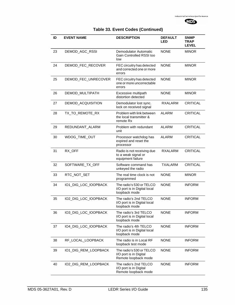
MDS 05-3627A01, Rev. D LEDR Series I/O Guide 135
23 DEMOD_AGC_RSSI Demodulator Automatic Gain Controlled RSSI too low
NONE MINOR
24 DEMOD_FEC_RECOVER FEC circuitry has detected and corrected one or more errors
NONE MINOR
25 DEMOD_FEC_UNRECOVER FEC circuitry has detected one or more uncorrectable errors
NONE MINOR
26 DEMOD_MULTIPATH Excessive multipath distortion detected
NONE MINOR
27 DEMOD_ACQUISITION Demodulator lost sync. lock on received signal
RXALARM CRITICAL
28 TX_TO_REMOTE_RX Problem with link between the local transmitter & remote Rx
ALARM CRITICAL
29 REDUNDANT_ALARM Problem with redundant unit
ALARM CRITICAL
30 WDOG_TIME_OUT Processor watchdog has expired and reset the processor
ALARM CRITICAL
31 RX_OFF Radio is not receiving due to a weak signal or equipment failure
RXALARM CRITICAL
32 SOFTWARE_TX_OFF Software command has unkeyed the radio
TXALARM CRITICAL
33 RTC_NOT_SET The real time clock is not programmed
NONE MINOR
34 IO1_DIG_LOC_lOOPBACK The radio’s 530 or TELCO I/O port is in Digital local loopback mode
NONE INFORM
35 IO2_DIG_LOC_lOOPBACK The radio’s 2nd TELCO I/O port is in Digital local loopback mode
NONE INFORM
36 IO3_DIG_LOC_lOOPBACK The radio’s 3rd TELCO I/O port is in Digital local loopback mode
NONE INFORM
37 IO4_DIG_LOC_lOOPBACK The radio’s 4th TELCO I/O port is in Digital local loopback mode
NONE INFORM
38 RF_LOCAL_LOOPBACK The radio is in Local RF loopback test mode
NONE INFORM
39 IO1_DIG_REM_LOOPBACK The radio’s 530 or TELCO I/O port is in Digital Remote loopback mode
NONE INFORM
40 IO2_DIG_REM_LOOPBACK The radio’s 2nd TELCO I/O port is in Digital Remote loopback mode
NONE INFORM
Table 33. Event Codes (Continued)
ID EVENT NAME DESCRIPTION DEFAULTLED
SNMP TRAP LEVEL
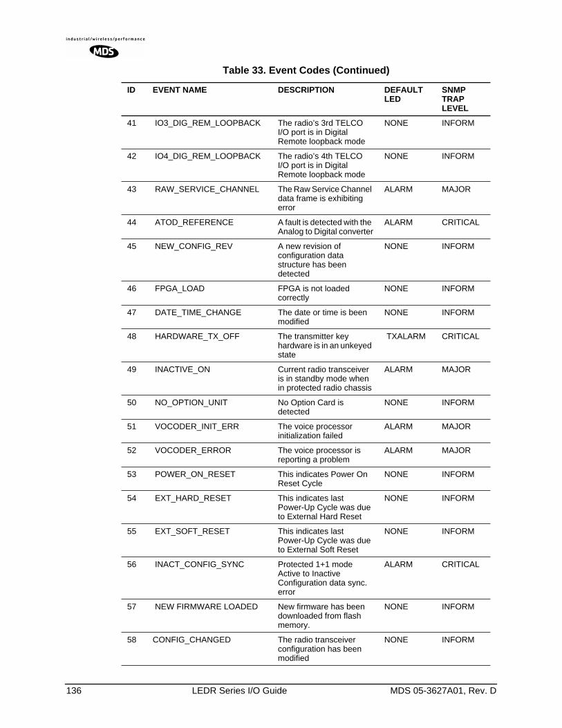
136 LEDR Series I/O Guide MDS 05-3627A01, Rev. D
41 IO3_DIG_REM_LOOPBACK The radio’s 3rd TELCO I/O port is in Digital Remote loopback mode
NONE INFORM
42 IO4_DIG_REM_LOOPBACK The radio’s 4th TELCO I/O port is in Digital Remote loopback mode
NONE INFORM
43 RAW_SERVICE_CHANNEL The Raw Service Channel data frame is exhibiting error
ALARM MAJOR
44 ATOD_REFERENCE A fault is detected with the Analog to Digital converter
ALARM CRITICAL
45 NEW_CONFIG_REV A new revision of configuration data structure has been detected
NONE INFORM
46 FPGA_LOAD FPGA is not loaded correctly
NONE INFORM
47 DATE_TIME_CHANGE The date or time is been modified
NONE INFORM
48 HARDWARE_TX_OFF The transmitter key hardware is in an unkeyed state
TXALARM CRITICAL
49 INACTIVE_ON Current radio transceiver is in standby mode when in protected radio chassis
ALARM MAJOR
50 NO_OPTION_UNIT No Option Card is detected
NONE INFORM
51 VOCODER_INIT_ERR The voice processor initialization failed
ALARM MAJOR
52 VOCODER_ERROR The voice processor is reporting a problem
ALARM MAJOR
53 POWER_ON_RESET This indicates Power On Reset Cycle
NONE INFORM
54 EXT_HARD_RESET This indicates last Power-Up Cycle was due to External Hard Reset
NONE INFORM
55 EXT_SOFT_RESET This indicates last Power-Up Cycle was due to External Soft Reset
NONE INFORM
56 INACT_CONFIG_SYNC Protected 1+1 mode Active to Inactive Configuration data sync. error
ALARM CRITICAL
57 NEW FIRMWARE LOADED New firmware has been downloaded from flash memory.
NONE INFORM
58 CONFIG_CHANGED The radio transceiver configuration has been modified
NONE INFORM
Table 33. Event Codes (Continued)
ID EVENT NAME DESCRIPTION DEFAULTLED
SNMP TRAP LEVEL
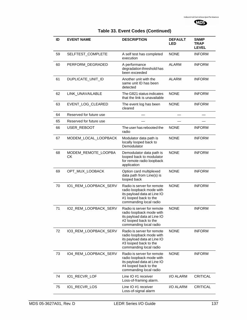
MDS 05-3627A01, Rev. D LEDR Series I/O Guide 137
59 SELFTEST_COMPLETE A self test has completed execution
NONE INFORM
60 PERFORM_DEGRADED A performance degradation threshold has been exceeded
ALARM INFORM
61 DUPLICATE_UNIT_ID Another unit with the same unit ID has been detected
ALARM INFORM
62 LINK_UNAVAILABLE The G821 status indicates that the link is unavailable
NONE INFORM
63 EVENT_LOG_CLEARED The event log has been cleared
NONE INFORM
64 Reserved for future use — — —
65 Reserved for future use — — —
66 USER_REBOOT The user has rebooted the radio
NONE INFORM
67 MODEM_LOCAL_LOOPBACK Modulator data path is locally looped back to Demodulator
NONE INFORM
68 MODEM_REMOTE_LOOPBACK
Demodulator data path is looped back to modulator for remote radio loopback application
NONE INFORM
69 OPT_MUX_LOOBACK Option card multiplexed data path from Line(s) is looped back
NONE INFORM
70 IO1_REM_LOOPBACK_SERV Radio is server for remote radio loopback mode with its payload data at Line IO #1 looped back to the commanding local radio
NONE INFORM
71 IO2_REM_LOOPBACK_SERV Radio is server for remote radio loopback mode with its payload data at Line IO #2 looped back to the commanding local radio
NONE INFORM
72 IO3_REM_LOOPBACK_SERV Radio is server for remote radio loopback mode with its payload data at Line IO #3 looped back to the commanding local radio
NONE INFORM
73 IO4_REM_LOOPBACK_SERV Radio is server for remote radio loopback mode with its payload data at Line IO #4 looped back to the commanding local radio
NONE INFORM
74 IO1_RECVR_LOF Line IO #1 receiver Loss-of-framing alarm.
I/O ALARM CRITICAL
75 IO1_RECVR_LOS Line IO #1 receiver Loss-of-signal alarm
I/O ALARM CRITICAL
Table 33. Event Codes (Continued)
ID EVENT NAME DESCRIPTION DEFAULTLED
SNMP TRAP LEVEL
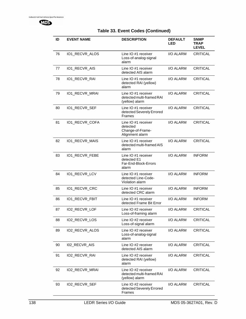
138 LEDR Series I/O Guide MDS 05-3627A01, Rev. D
76 IO1_RECVR_ALOS Line IO #1 receiver Loss-of-analog-signal alarm
I/O ALARM CRITICAL
77 IO1_RECVR_AIS Line IO #1 receiver detected AIS alarm
I/O ALARM CRITICAL
78 IO1_RECVR_RAI Line IO #1 receiver detected RAI (yellow) alarm
I/O ALARM CRITICAL
79 IO1_RECVR_MRAI Line IO #1 receiver detected multi-framed RAI (yellow) alarm
I/O ALARM CRITICAL
80 IO1_RECVR_SEF Line IO #1 receiver detected Severely Errored Frames
I/O ALARM CRITICAL
81 IO1_RECVR_COFA Line IO #1 receiver detected Change-of-Frame-Alignment alarm
I/O ALARM CRITICAL
82 IO1_RECVR_MAIS Line IO #1 receiver detected multi-framed AIS alarm
I/O ALARM CRITICAL
83 IO1_RECVR_FEBE Line IO #1 receiver detected E1 Far-End-Block-Errors alarm
I/O ALARM INFORM
84 IO1_RECVR_LCV Line IO #1 receiver detected Line-Code-Violation alarm
I/O ALARM INFORM
85 IO1_RECVR_CRC Line IO #1 receiver detected CRC alarm
I/O ALARM INFORM
86 IO1_RECVR_FBIT Line IO #1 receiver detected Frame Bit Error
I/O ALARM INFORM
87 IO2_RECVR_LOF Line IO #2 receiver Loss-of-framing alarm
I/O ALARM CRITICAL
88 IO2_RECVR_LOS Line IO #2 receiver Loss-of-signal alarm
I/O ALARM CRITICAL
89 IO2_RECVR_ALOS Line IO #2 receiver Loss-of-analog-signal alarm
I/O ALARM CRITICAL
90 I02_RECVR_AIS Line IO #2 receiver detected AIS alarm
I/O ALARM CRITICAL
91 IO2_RECVR_RAI Line IO #2 receiver detected RAI (yellow) alarm
I/O ALARM CRITICAL
92 IO2_RECVR_MRAI Line IO #2 receiver detected multi-framed RAI (yellow) alarm
I/O ALARM CRITICAL
93 IO2_RECVR_SEF Line IO #2 receiver detected Severely Errored Frames
I/O ALARM CRITICAL
Table 33. Event Codes (Continued)
ID EVENT NAME DESCRIPTION DEFAULTLED
SNMP TRAP LEVEL
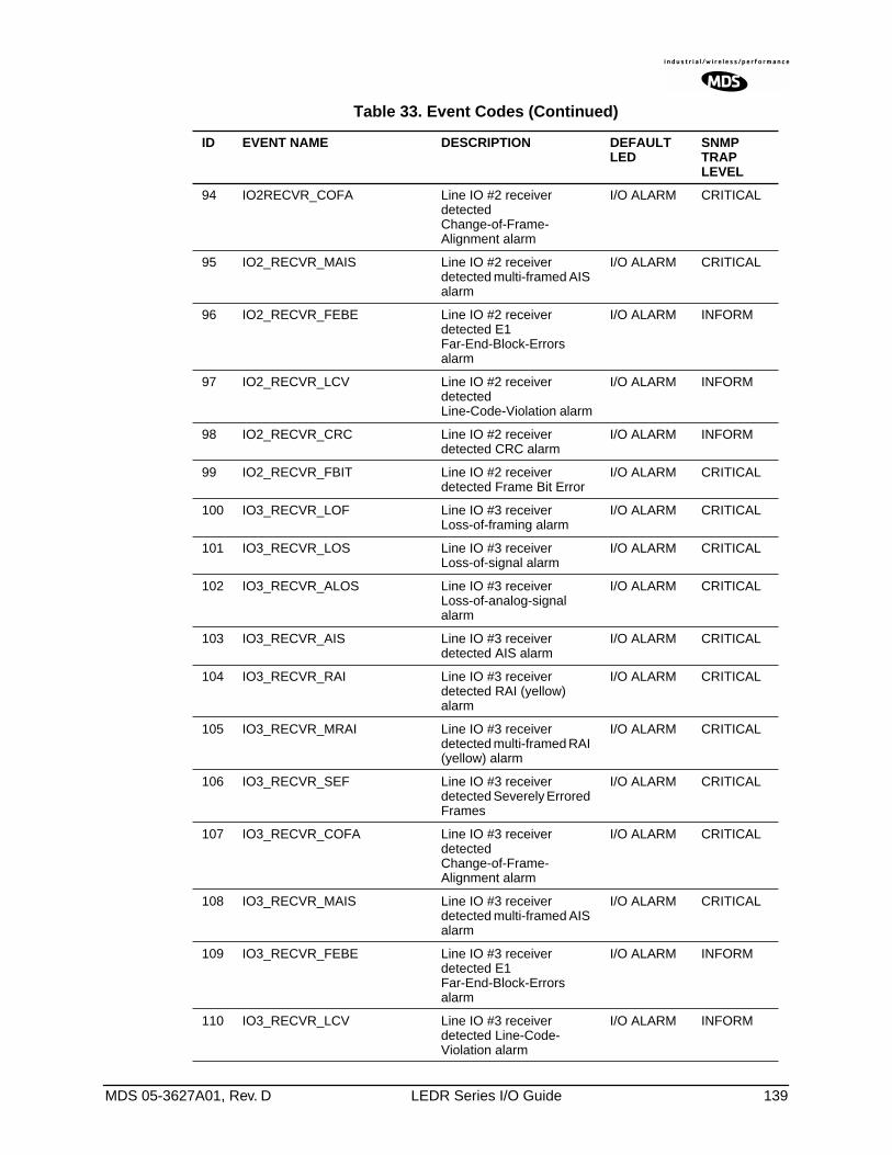
MDS 05-3627A01, Rev. D LEDR Series I/O Guide 139
94 IO2RECVR_COFA Line IO #2 receiver detected Change-of-Frame-Alignment alarm
I/O ALARM CRITICAL
95 IO2_RECVR_MAIS Line IO #2 receiver detected multi-framed AIS alarm
I/O ALARM CRITICAL
96 IO2_RECVR_FEBE Line IO #2 receiver detected E1 Far-End-Block-Errors alarm
I/O ALARM INFORM
97 IO2_RECVR_LCV Line IO #2 receiver detected Line-Code-Violation alarm
I/O ALARM INFORM
98 IO2_RECVR_CRC Line IO #2 receiver detected CRC alarm
I/O ALARM INFORM
99 IO2_RECVR_FBIT Line IO #2 receiver detected Frame Bit Error
I/O ALARM CRITICAL
100 IO3_RECVR_LOF Line IO #3 receiver Loss-of-framing alarm
I/O ALARM CRITICAL
101 IO3_RECVR_LOS Line IO #3 receiver Loss-of-signal alarm
I/O ALARM CRITICAL
102 IO3_RECVR_ALOS Line IO #3 receiver Loss-of-analog-signal alarm
I/O ALARM CRITICAL
103 IO3_RECVR_AIS Line IO #3 receiver detected AIS alarm
I/O ALARM CRITICAL
104 IO3_RECVR_RAI Line IO #3 receiver detected RAI (yellow) alarm
I/O ALARM CRITICAL
105 IO3_RECVR_MRAI Line IO #3 receiver detected multi-framed RAI (yellow) alarm
I/O ALARM CRITICAL
106 IO3_RECVR_SEF Line IO #3 receiver detected Severely Errored Frames
I/O ALARM CRITICAL
107 IO3_RECVR_COFA Line IO #3 receiver detected Change-of-Frame-Alignment alarm
I/O ALARM CRITICAL
108 IO3_RECVR_MAIS Line IO #3 receiver detected multi-framed AIS alarm
I/O ALARM CRITICAL
109 IO3_RECVR_FEBE Line IO #3 receiver detected E1 Far-End-Block-Errors alarm
I/O ALARM INFORM
110 IO3_RECVR_LCV Line IO #3 receiver detected Line-Code-Violation alarm
I/O ALARM INFORM
Table 33. Event Codes (Continued)
ID EVENT NAME DESCRIPTION DEFAULTLED
SNMP TRAP LEVEL
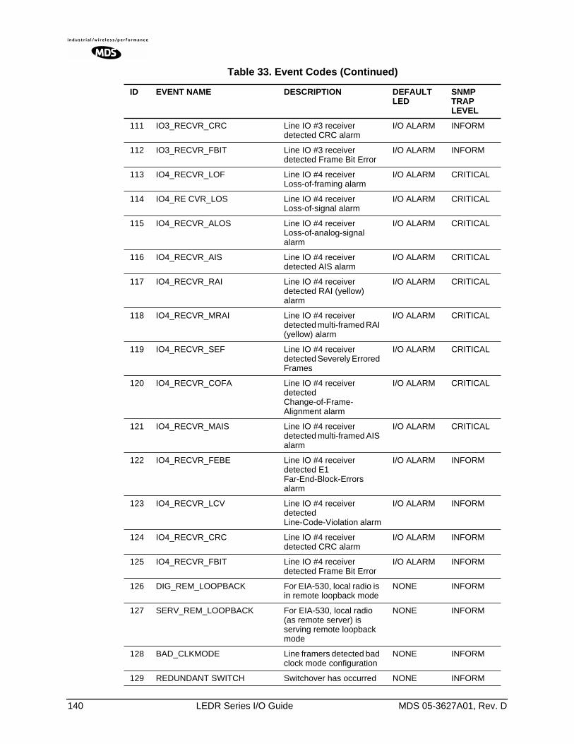
140 LEDR Series I/O Guide MDS 05-3627A01, Rev. D
111 IO3_RECVR_CRC Line IO #3 receiver detected CRC alarm
I/O ALARM INFORM
112 IO3_RECVR_FBIT Line IO #3 receiver detected Frame Bit Error
I/O ALARM INFORM
113 IO4_RECVR_LOF Line IO #4 receiver Loss-of-framing alarm
I/O ALARM CRITICAL
114 IO4_RE CVR_LOS Line IO #4 receiver Loss-of-signal alarm
I/O ALARM CRITICAL
115 IO4_RECVR_ALOS Line IO #4 receiver Loss-of-analog-signal alarm
I/O ALARM CRITICAL
116 IO4_RECVR_AIS Line IO #4 receiver detected AIS alarm
I/O ALARM CRITICAL
117 IO4_RECVR_RAI Line IO #4 receiver detected RAI (yellow) alarm
I/O ALARM CRITICAL
118 IO4_RECVR_MRAI Line IO #4 receiver detected multi-framed RAI (yellow) alarm
I/O ALARM CRITICAL
119 IO4_RECVR_SEF Line IO #4 receiver detected Severely Errored Frames
I/O ALARM CRITICAL
120 IO4_RECVR_COFA Line IO #4 receiver detected Change-of-Frame-Alignment alarm
I/O ALARM CRITICAL
121 IO4_RECVR_MAIS Line IO #4 receiver detected multi-framed AIS alarm
I/O ALARM CRITICAL
122 IO4_RECVR_FEBE Line IO #4 receiver detected E1 Far-End-Block-Errors alarm
I/O ALARM INFORM
123 IO4_RECVR_LCV Line IO #4 receiver detected Line-Code-Violation alarm
I/O ALARM INFORM
124 IO4_RECVR_CRC Line IO #4 receiver detected CRC alarm
I/O ALARM INFORM
125 IO4_RECVR_FBIT Line IO #4 receiver detected Frame Bit Error
I/O ALARM INFORM
126 DIG_REM_LOOPBACK For EIA-530, local radio is in remote loopback mode
NONE INFORM
127 SERV_REM_LOOPBACK For EIA-530, local radio (as remote server) is serving remote loopback mode
NONE INFORM
128 BAD_CLKMODE Line framers detected bad clock mode configuration
NONE INFORM
129 REDUNDANT SWITCH Switchover has occurred NONE INFORM
Table 33. Event Codes (Continued)
ID EVENT NAME DESCRIPTION DEFAULTLED
SNMP TRAP LEVEL
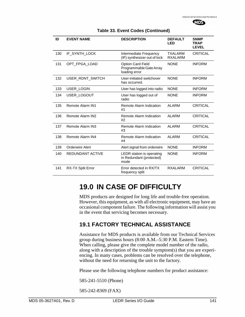
MDS 05-3627A01, Rev. D LEDR Series I/O Guide 141
19.0 IN CASE OF DIFFICULTYMDS products are designed for long life and trouble-free operation. However, this equipment, as with all electronic equipment, may have an occasional component failure. The following information will assist you in the event that servicing becomes necessary.
19.1 FACTORY TECHNICAL ASSISTANCE
Assistance for MDS products is available from our Technical Services group during business hours (8:00 A.M.–5:30 P.M. Eastern Time). When calling, please give the complete model number of the radio, along with a description of the trouble symptom(s) that you are experi-encing. In many cases, problems can be resolved over the telephone, without the need for returning the unit to the factory.
Please use the following telephone numbers for product assistance:
585-241-5510 (Phone)
585-242-8369 (FAX)
130 IF_SYNTH_LOCK Intermediate Frequency (IF) synthesizer out of lock
TXALARM RXALARM
CRITICAL
131 OPT_FPGA_LOAD Option Card Field Programmable Gate Array loading error
NONE INFORM
132 USER_RDNT_SWITCH User-initiated switchover has occurred.
NONE INFORM
133 USER_LOGIN User has logged into radio NONE INFORM
134 USER_LOGOUT User has logged out of radio
NONE INFORM
135 Remote Alarm IN1 Remote Alarm Indication #1
ALARM CRITICAL
136 Remote Alarm IN2 Remote Alarm Indication #2
ALARM CRITICAL
137 Remote Alarm IN3 Remote Alarm Indication #3
ALARM CRITICAL
138 Remote Alarm IN4 Remote Alarm Indication #4
ALARM CRITICAL
139 Orderwire Alert Alert signal from orderwire NONE INFORM
140 REDUNDANT ACTIVE LEDR station is operating in Redundant (protected) mode
NONE INFORM
141 RX-TX Split Error Error detected in RX/TX frequency split
RXALARM CRITICAL
Table 33. Event Codes (Continued)
ID EVENT NAME DESCRIPTION DEFAULTLED
SNMP TRAP LEVEL
142 LEDR Series I/O Guide MDS 05-3627A01, Rev. D
19.2 FACTORY REPAIRS
Component level repair of radio equipment is not recommended in the field. Many components are installed using surface mount technology, which requires specialized training and equipment for proper servicing. For this reason, the equipment should be returned to the factory for any PC board repairs. The factory is best equipped to diagnose, repair and align your radio to its proper operating specifications.
If return of the equipment is necessary, you will be issued a Service Request Order (SRO) number. The SRO number will help expedite the repair so that the equipment can be repaired and returned to you as quickly as possible. Please be sure to include this number on the outside of the shipping box, and on any correspondence relating to the repair. No equipment can be accepted for repair without an SRO number.
A statement should accompany the radio describing, in detail, the trouble symptom(s), and a description of any associated equipment nor-mally connected to the radio. It is also important to include the name and telephone number of a person in your organization who can be contacted if additional information is required.
The radio must be properly packed for return to the factory. The original shipping container and packaging materials should be used whenever possible. All factory returns should be addressed to:
When repairs have been completed, the equipment will be returned to you by the same shipping method used to send it to the factory. Please specify if you wish to make different shipping arrangements. To inquire about an in-process repair, you may contact our Product Services Group at 585-241-5540 (FAX: 585-242-8400, or via e-mail at the folowing address: [email protected].
Microwave Data Systems Inc.Product Service Department(SRO No. XXXX)175 Science ParkwayRochester, NY 14620 USA

MDS 05-3627A01, Rev. D LEDR Series Installation & Operation Guide G-1
GLOSSARY
AIS—Alarm Indication Signal. Indicates all ones are being sent or received.
AMI—Alternate Mark Inversion. A bipolar format where consecutive marks (ones) have the polarity inverted. Spaces (ones) are repre-sented by zero volts. This technique prevents long sequences of positive or negative volt-ages.
Analog—Signals with a continuously varying amplitude, such as the human voice.
BERT—Bit-error rate test. The results of a BERT are normally expressed as a ratio (power of 10) of the number of bits received in error compared to the total number received.
BER—Bit-error rate. See also BERT.
Bit—Binary digit. The smallest unit of digital data, often represented by a one or a zero. Eight bits usually comprise a byte.
bps—Bits-per-second. A measure of the infor-mation transfer rate of digital data across a communication channel.
BSLIP—Bit Slip. Protocol that allows a bit to be added or deleted without causing a reframe sequence. Applies principally to Dutch PTT National applications.
Byte—A digital “word” usually made up of eight bits.
cas—Channel Associated Signalling.
dBi—Decibels of gain relative to an isotropic radiator. (A hypothetical antenna which radi-ates equally in all directions.) Used to express antenna gain.
dBm—Decibels relative to one milliwatt. An absolute unit used to measure signal power, as in transmitter power output, or received signal strength.
DTR—Data Terminal Ready. A control signal sent from the radio indicating that it is ready to transmit data.
CPE—Customer premise (provided) equip-ment.
DCE— Data (circuit terminating) Communi-cations Equipment. In data communications terminology, this is the “modem” side of a computer-to-modem connection. The trans-ceiver is a DCE device which is designed to connect to a DTE device.
Decibel (dB)—A measure of the ratio between two signal levels. Frequently used to express the gain or loss of a system.
DSP—Digital Signal Processing. A processing technique that uses software algorithms to filter, shape, or otherwise modify the character-istics of a given signal. In the LEDR radio, DSP is used primarily in modulation and demodula-tion functions.
E1—An international telephony standard that operates at 2.048 megabits-per-second (Mbps). This transmission speed is commonly used throughout the world except for North America (which uses T1 1.544 Mbps). Framed E1 con-sists of 30 digitized telephone channels and two 64 Kbps control channels.
EIRP—Effective Isotropic Radiated Power. Commonly used to express the power radiated from a gain antenna. It is equal to the power transmitted (minus feedline loss) plus the antenna gain.
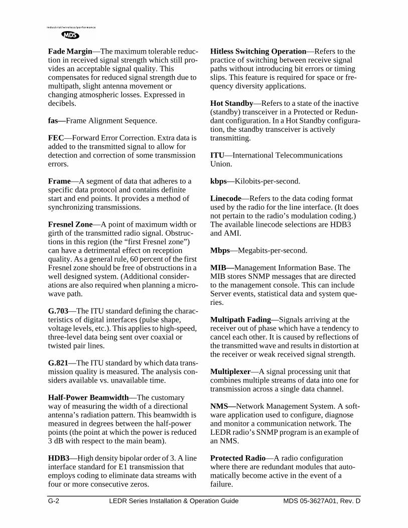
G-2 LEDR Series Installation & Operation Guide MDS 05-3627A01, Rev. D
Fade Margin—The maximum tolerable reduc-tion in received signal strength which still pro-vides an acceptable signal quality. This compensates for reduced signal strength due to multipath, slight antenna movement or changing atmospheric losses. Expressed in decibels.
fas—Frame Alignment Sequence.
FEC—Forward Error Correction. Extra data is added to the transmitted signal to allow for detection and correction of some transmission errors.
Frame—A segment of data that adheres to a specific data protocol and contains definite start and end points. It provides a method of synchronizing transmissions.
Fresnel Zone—A point of maximum width or girth of the transmitted radio signal. Obstruc-tions in this region (the “first Fresnel zone”) can have a detrimental effect on reception quality. As a general rule, 60 percent of the first Fresnel zone should be free of obstructions in a well designed system. (Additional consider-ations are also required when planning a micro-wave path.
G.703—The ITU standard defining the charac-teristics of digital interfaces (pulse shape, voltage levels, etc.). This applies to high-speed, three-level data being sent over coaxial or twisted pair lines.
G.821—The ITU standard by which data trans-mission quality is measured. The analysis con-siders available vs. unavailable time.
Half-Power Beamwidth—The customary way of measuring the width of a directional antenna’s radiation pattern. This beamwidth is measured in degrees between the half-power points (the point at which the power is reduced 3 dB with respect to the main beam).
HDB3—High density bipolar order of 3. A line interface standard for E1 transmission that employs coding to eliminate data streams with four or more consecutive zeros.
Hitless Switching Operation—Refers to the practice of switching between receive signal paths without introducing bit errors or timing slips. This feature is required for space or fre-quency diversity applications.
Hot Standby—Refers to a state of the inactive (standby) transceiver in a Protected or Redun-dant configuration. In a Hot Standby configura-tion, the standby transceiver is actively transmitting.
ITU—International Telecommunications Union.
kbps—Kilobits-per-second.
Linecode—Refers to the data coding format used by the radio for the line interface. (It does not pertain to the radio’s modulation coding.) The available linecode selections are HDB3 and AMI.
Mbps—Megabits-per-second.
MIB—Management Information Base. The MIB stores SNMP messages that are directed to the management console. This can include Server events, statistical data and system que-ries.
Multipath Fading—Signals arriving at the receiver out of phase which have a tendency to cancel each other. It is caused by reflections of the transmitted wave and results in distortion at the receiver or weak received signal strength.
Multiplexer—A signal processing unit that combines multiple streams of data into one for transmission across a single data channel.
NMS—Network Management System. A soft-ware application used to configure, diagnose and monitor a communication network. The LEDR radio’s SNMP program is an example of an NMS.
Protected Radio—A radio configuration where there are redundant modules that auto-matically become active in the event of a failure.
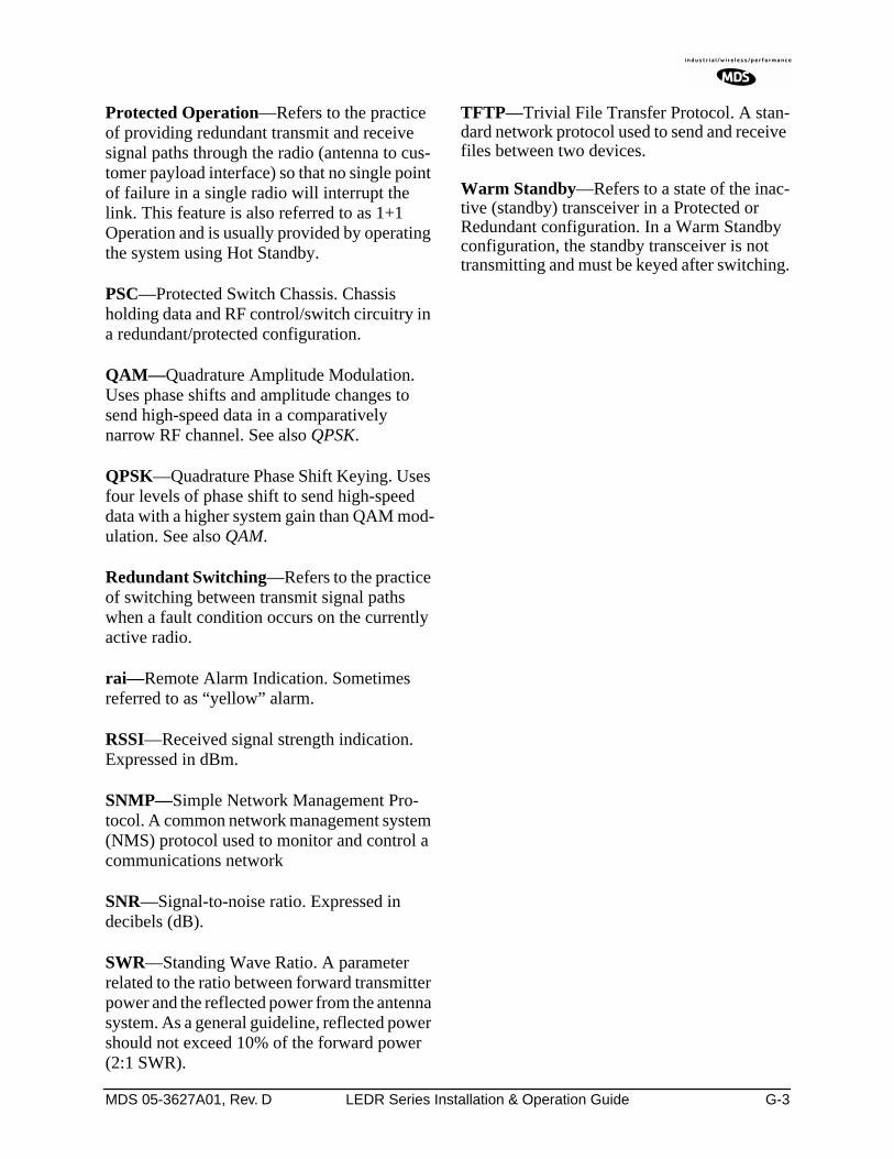
MDS 05-3627A01, Rev. D LEDR Series Installation & Operation Guide G-3
Protected Operation—Refers to the practice of providing redundant transmit and receive signal paths through the radio (antenna to cus-tomer payload interface) so that no single point of failure in a single radio will interrupt the link. This feature is also referred to as 1+1 Operation and is usually provided by operating the system using Hot Standby.
PSC—Protected Switch Chassis. Chassis holding data and RF control/switch circuitry in a redundant/protected configuration.
QAM—Quadrature Amplitude Modulation. Uses phase shifts and amplitude changes to send high-speed data in a comparatively narrow RF channel. See also QPSK.
QPSK—Quadrature Phase Shift Keying. Uses four levels of phase shift to send high-speed data with a higher system gain than QAM mod-ulation. See also QAM.
Redundant Switching—Refers to the practice of switching between transmit signal paths when a fault condition occurs on the currently active radio.
rai—Remote Alarm Indication. Sometimes referred to as “yellow” alarm.
RSSI—Received signal strength indication. Expressed in dBm.
SNMP—Simple Network Management Pro-tocol. A common network management system (NMS) protocol used to monitor and control a communications network
SNR—Signal-to-noise ratio. Expressed in decibels (dB).
SWR—Standing Wave Ratio. A parameter related to the ratio between forward transmitter power and the reflected power from the antenna system. As a general guideline, reflected power should not exceed 10% of the forward power (2:1 SWR).
TFTP—Trivial File Transfer Protocol. A stan-dard network protocol used to send and receive files between two devices.
Warm Standby—Refers to a state of the inac-tive (standby) transceiver in a Protected or Redundant configuration. In a Warm Standby configuration, the standby transceiver is not transmitting and must be keyed after switching.

G-4 LEDR Series Installation & Operation Guide MDS 05-3627A01, Rev. D
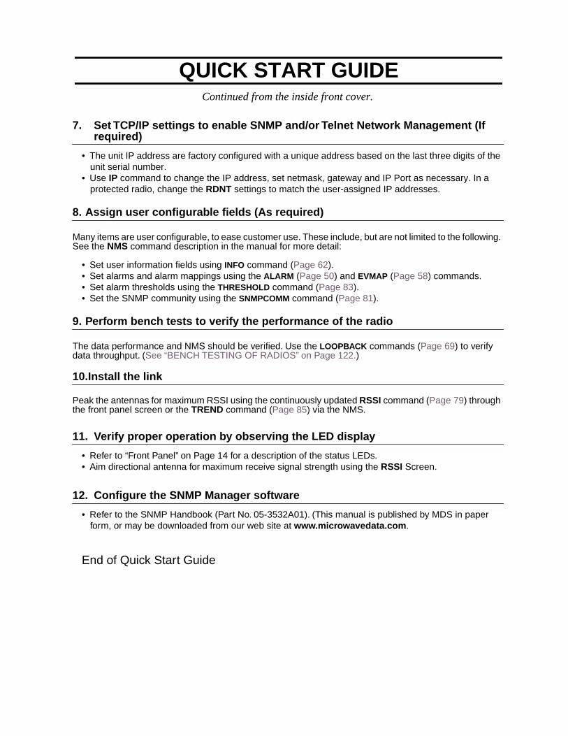
Continued from the inside front cover.
7. Set TCP/IP settings to enable SNMP and/or Telnet Network Management (If required)
• The unit IP address are factory configured with a unique address based on the last three digits of the unit serial number.
• Use IP command to change the IP address, set netmask, gateway and IP Port as necessary. In a protected radio, change the RDNT settings to match the user-assigned IP addresses.
8. Assign user configurable fields (As required)
Many items are user configurable, to ease customer use. These include, but are not limited to the following. See the NMS command description in the manual for more detail:
• Set user information fields using INFO command (Page 62).• Set alarms and alarm mappings using the ALARM (Page 50) and EVMAP (Page 58) commands.• Set alarm thresholds using the THRESHOLD command (Page 83).• Set the SNMP community using the SNMPCOMM command (Page 81).
9. Perform bench tests to verify the performance of the radio
The data performance and NMS should be verified. Use the LOOPBACK commands (Page 69) to verify data throughput. (See “BENCH TESTING OF RADIOS” on Page 122.)
10.Install the link
Peak the antennas for maximum RSSI using the continuously updated RSSI command (Page 79) through the front panel screen or the TREND command (Page 85) via the NMS.
11. Verify proper operation by observing the LED display
• Refer to “Front Panel” on Page 14 for a description of the status LEDs.• Aim directional antenna for maximum receive signal strength using the RSSI Screen.
12. Configure the SNMP Manager software
• Refer to the SNMP Handbook (Part No. 05-3532A01). (This manual is published by MDS in paper form, or may be downloaded from our web site at www.microwavedata.com.
End of Quick Start Guide
QUICK START GUIDE

Microwave Data Systems Inc.
Rochester, NY 14620General Business: +1 585 242-9600
FAX: +1 585 242-9620Web: www.microwavedata.com
175 Science Parkway
A product of Microwave Data Systems Inc.