Embed Size (px)
Citation preview

www.tridonic.com 1Subject to change without notice.
Data sheet 03/18-LC461-4
LED Driver
Constant voltage
Product description• Constant voltage LED Driver
• Universal input voltage range
• Constant output voltage
• Push terminals for simple wiring
• Nominal life-time up to 50,000 h (at ta 113 °F with a
failure rate max. 0.2 % per 1,000 h)
• 5-year guarantee
• Suitable for emergency installations according to
IEC 50172
• Complies with CLASS C from minimum to maximum
load range according to IEC 61000-3-2
Properties• Small design
• High efficiency
• Low power loss
• Overtemperature and overload protection
• Short-circuit shutdown feature with automatic restart
• UL1310 class II, SELV
• Type of protection IP20
• For dry location only
• Plastic casing white
Driver LCU 100/96W 12/24V IP20 EXC
EXCITE indoor IP20 series
EL

www.tridonic.com 2Subject to change without notice.
Data sheet 03/18-LC461-4
LED Driver
Constant voltage
Specific technical dataType Max. casing temperature tc Output voltage Max. input power Output current range
LCU 100W 12V SR TOP 185 °F 12 V 117 W 0.83 – 8.33 A
LCU 96W 24V SR TOP 185 °F 24 V 117 W 0.40 – 4.00 A
1 For input voltage from 120 to 277 V AC (50 / 60 Hz) with 100 % load. For input voltage from 100 to 120 V AC (50 / 60 Hz) with 80 % load.
Technical dataRated supply voltage 120 – 277 V
AC voltage range 108 – 305 V
DC voltage range 176 – 288 V
Rated current 12 V (at 120 V 60 Hz) 0.98 A
Rated current 12 V (at 277 V 60 Hz) 0.43 A
Rated current 24 V (at 120 V 60 Hz) 0.92 A
Rated current 24 V (at 277 V 60 Hz) 0.40 A
Mains frequency 0 / 50 / 60 Hz
Efficiency (at 120 V 60 Hz) > 88 %
Efficiency (at 277 V 60 Hz) > 91 %
λ (at 120 V 60 Hz) 0.99
λ (at 277 V 60 Hz) 0.95
Output voltage tolerance 12 V -0 /+10 %
Output voltage tolerance 24 V -0 /+5 %
Output power 12 V (ta ≤ 60 °C) 100 W
Output power 12 V (ta > 60 °C) 70 W
Output power 24 V (ta ≤ 50 °C) 96 W
Output power 24 V (ta > 50 °C) 67 W
Output power range 12 V 10 – 100 W
Output power range 24 V 10 – 96 W
Turn on time (output) ≤ 0.5 s
Turn off time (output) ≤ 1 s
Hold on time at power failure (Output) 10 ms
Mains surge capability (between L - N) 1 kV
Mains surge capability (between L/N - PE) 1 kV
Surge voltage at output side (against PE) < 500 V
Ambient temperature ta (12 V) -13 ... +158 °F
Ambient temperature ta (24 V) -13 ... +140 °F
Ambient temperature ta (at life-time 50,000 h)1 -13 ... +113 °F
Storage temperature -40 ... +185 °F
Dimensions LxWxH for 12 V 11.81 x 1.73 x 0.91 inch
Dimensions LxWxH for 24 V 11.81 x 1.57 x 0.83 inch
Hole spacing D 10.75 inch
Driver LCU 100/96W 12/24V IP20 EXC
EXCITE series
300 / 11.81
273 / 10.75
23 0.91
44 1.73
22 0.87
7.2
0.28
4.2
0.17
LCU 100W 12V SR TOP
22 0.87
7.2
0.28
4.2
0.17
21 0.83
40 1.57
300 / 11.81
273 / 10.75
LCU 96W 24V SR TOP
Dimensions in mm / inch
Ordering dataType Article number Packaging carton Packaging pallet Weight per pc.
LCU 100W 12V SR TOP 28000408 20 pc(s). 1,000 pc(s). 1.01 lbs
LCU 96W 24V SR TOP 28000413 20 pc(s). 1,000 pc(s). 0.75 lbs

www.tridonic.com 3Subject to change without notice.
Data sheet 03/18-LC461-4
LED Driver
Constant voltage
StandardsIEC 55015IEC 60598-1IEC 60598-2-22IEC 61000-3-2IEC 61000-3-3IEC 61347-1 IEC 61347-2-13 IEC 61547 IEC 62384IEC 62493Acc. to IEC 50172: suitabel for central battery systemsUL879UL8750CSA22
Harmonic distortion in the mains supply (at 120 V / 60 Hz and full load) in %
Type THD 3 5 7 9 11
LCU 100W 12V SR TOP 13 12 5 3 1 1
LCU 96W 24V SR TOP 14 2 1 1 1 1
Harmonic distortion in the mains supply (at 277 V / 60 Hz and full load) in %
Type THD 3 5 7 9 11
LCU 100W 12V SR TOP 14 6 2 2 1 1
LCU 96W 24V SR TOP 14 5 2 2 1 1
Expected life-timeType Output voltage ta 95 °F 113 °F 131 °F
LCU 100W 12V SR TOP 12 Vtc 155 °F 174 °F 191 °F
Life-time > 100,000 h > 50,000 h > 25,000 h
LCU 96W 24V SR TOP 24 Vtc 148 °F 166 °F 184 °F
Life-time > 100,000 h > 50,000 h > 25,000 h
LN
LCU ... SR TOP
100-277 VAC
Wiring diagram Wiring type and cross sectionThe wiring can be in stranded wires with ferrules or solid. For perfect function of the screw terminals the strip length should be 9–10 mm / 0.35 – 0.39 inch for the terminal.
The maximum secondary cable length at the terminals is 2 m / 78.7 inch. The LED wiring should be kept as short as possible to ensure good EMC.
Input / Output terminal
Installation instructionsThe switching of LEDs on secondary side is not permitted.The functioning of the LCU in combination with dimming devices (e.g. PWM)cannot be guaranteed and has to be checked individually before using in combination.
Overload protectionAutomatic shutdown of the LED Driver if the maximum output current is exceeded. Automatic restart if the output current is below the limit.
Over temperature protectionAutomatic shutdown of the LED Driver if the temperature limit is exceeded.Automatic restart if the temperature falls below the limit.
No-load operationThe LED Driver is not damaged in the no-load operation. The max. output voltage (see page1) can be obtained during no-load operation.
Short-circuit behaviourIn case of a short circuit on the secondary side (LED) the LED Driver switches into hiccup mode. After removal of the short-circuit fault the LED Driver will recover automatically.
Glow wire testaccording to IEC 61347-1 with increased temperature of 850 °C / 1,562 °F passed.
Min. Ø mm / inchMax. Ø mm / inch
– mm²AWG – AWG
– mm– inch
PRI and SEC:20 AWG – 16 AWG
Release of the wiring:The terminals have a simple push-in termination. Conductor removal via screwdriver (2.5 x 0.4 mm / 0.10 x 0.02 inch).

www.tridonic.com 4Subject to change without notice.
Data sheet 03/18-LC461-4
LED Driver
Constant voltage
Isolation and electric strength testing of luminairesElectronic devices can be damaged by high voltage. This has to be considered during the routine testing of the luminaires in production.
According to IEC 60598-1 Annex Q (informative only!) or ENEC 303-Annex A, each luminaire should be submitted to an isolation test with 500 V DC for 1 second. This test voltage should be connected between the interconnected phase and neutral terminals and the earth terminal. The isolation resistance must be at least 2 MΩ.
As an alternative, IEC 60598-1 Annex Q describes a test of the electrical strength with 1500 V AC (or 1.414 x 1500 V DC). To avoid damage to the electronic devices this test must not be conducted.
Additional information
Additional technical information at www.tridonic.com → Technical Data
Guarantee conditions at www.tridonic.com → Services
Life-time declarations are informative and represent no warranty claim.No warranty if device was opened.
THD vs load
12
15
13
18
20
55 80 85 90 9570 7560 65 100
19
16
17
14
Load [%]
TH
D [%
]
Efficiency vs load
87
88
89
90
91
55 70 75 80 85 90 9560 65 100
92
Load [%]
Eic
ienc
y [%
]
Power factor vs load
Diagrams for 12 V
0.86
0.88
0.90
0.92
0.94
0.96
0.98
1.00
55 70 75 80 85 90 9560 65 100
Load [%]
Pow
er fa
ctor
120 V
277 V230 V
www.tridonic.com 5Subject to change without notice.
Data sheet 03/18-LC461-4
LED Driver
Constant voltage
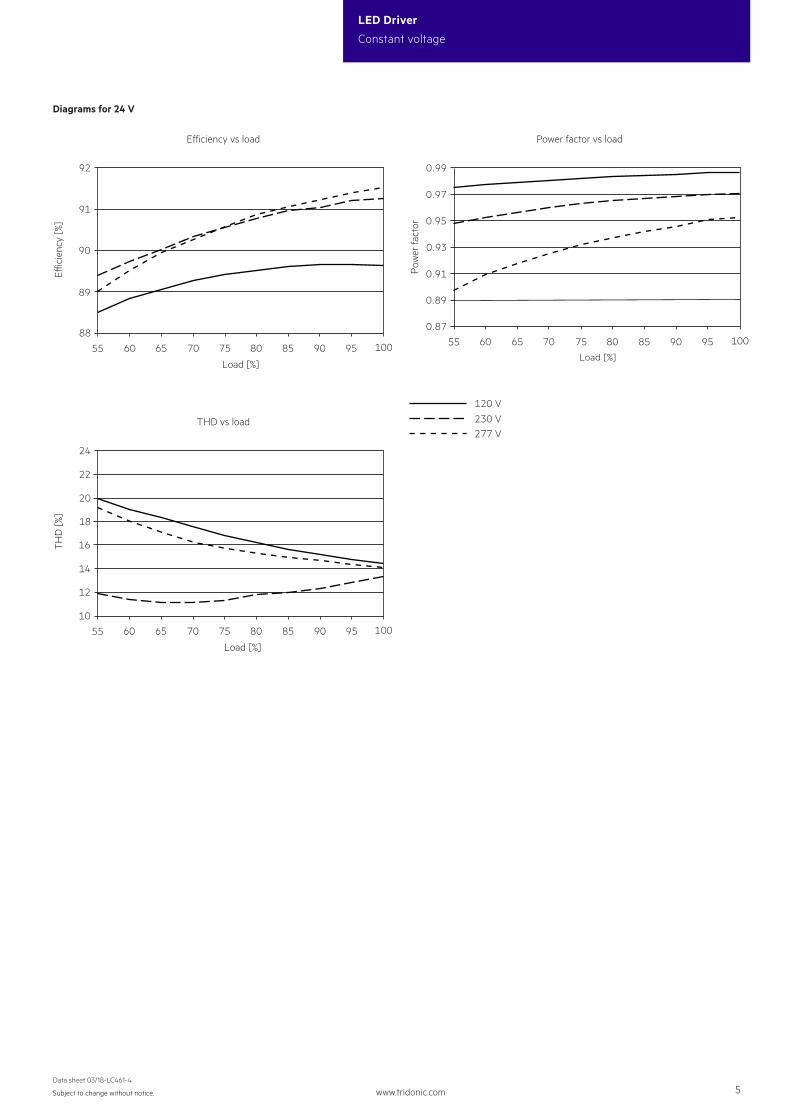
THD vs load
10
16
12
22
24
55 80 85 90 9570 7560 65 100
20
18
14
Load [%]
TH
D [%
]
Efficiency vs load
88
89
90
91
55 70 75 80 85 90 9560 65 100
92
Load [%]
Eic
ienc
y [%
]
Power factor vs load
Diagrams for 24 V
0.87
0.89
0.91
0.93
0.95
0.97
0.99
55 70 75 80 85 90 9560 65 100
Load [%]
Pow
er fa
ctor
120 V
277 V230 V


![function [A, W] = fpica(X, whiteningMatrix ... filefunction [A, W] = fpica(X, whiteningMatrix, dewhiteningMatrix, approach, ... numOfIC, g, finetune, a1, a2, myy, stabilization,](https://img.pdfslide.us/doc/110x75/5d637ea688c9936c668bde39/function-a-w-fpicax-whiteningmatrix-a-w-fpicax-whiteningmatrix.jpg)